KR101409885B1 - Encapsulated electroluminescent device - Google Patents
Encapsulated electroluminescent device Download PDFInfo
- Publication number
- KR101409885B1 KR101409885B1 KR1020097004450A KR20097004450A KR101409885B1 KR 101409885 B1 KR101409885 B1 KR 101409885B1 KR 1020097004450 A KR1020097004450 A KR 1020097004450A KR 20097004450 A KR20097004450 A KR 20097004450A KR 101409885 B1 KR101409885 B1 KR 101409885B1
- Authority
- KR
- South Korea
- Prior art keywords
- protective
- substrate
- electrically conductive
- lid
- electrode
- Prior art date
Links
Images


Classifications
-
- H—ELECTRICITY
- H10—SEMICONDUCTOR DEVICES; ELECTRIC SOLID-STATE DEVICES NOT OTHERWISE PROVIDED FOR
- H10K—ORGANIC ELECTRIC SOLID-STATE DEVICES
- H10K50/00—Organic light-emitting devices
- H10K50/80—Constructional details
- H10K50/84—Passivation; Containers; Encapsulations
- H10K50/842—Containers
- H10K50/8426—Peripheral sealing arrangements, e.g. adhesives, sealants
-
- B—PERFORMING OPERATIONS; TRANSPORTING
- B32—LAYERED PRODUCTS
- B32B—LAYERED PRODUCTS, i.e. PRODUCTS BUILT-UP OF STRATA OF FLAT OR NON-FLAT, e.g. CELLULAR OR HONEYCOMB, FORM
- B32B17/00—Layered products essentially comprising sheet glass, or glass, slag, or like fibres
- B32B17/06—Layered products essentially comprising sheet glass, or glass, slag, or like fibres comprising glass as the main or only constituent of a layer, next to another layer of a specific material
- B32B17/10—Layered products essentially comprising sheet glass, or glass, slag, or like fibres comprising glass as the main or only constituent of a layer, next to another layer of a specific material of synthetic resin
- B32B17/10005—Layered products essentially comprising sheet glass, or glass, slag, or like fibres comprising glass as the main or only constituent of a layer, next to another layer of a specific material of synthetic resin laminated safety glass or glazing
- B32B17/10165—Functional features of the laminated safety glass or glazing
- B32B17/10541—Functional features of the laminated safety glass or glazing comprising a light source or a light guide
-
- B—PERFORMING OPERATIONS; TRANSPORTING
- B32—LAYERED PRODUCTS
- B32B—LAYERED PRODUCTS, i.e. PRODUCTS BUILT-UP OF STRATA OF FLAT OR NON-FLAT, e.g. CELLULAR OR HONEYCOMB, FORM
- B32B17/00—Layered products essentially comprising sheet glass, or glass, slag, or like fibres
- B32B17/06—Layered products essentially comprising sheet glass, or glass, slag, or like fibres comprising glass as the main or only constituent of a layer, next to another layer of a specific material
- B32B17/10—Layered products essentially comprising sheet glass, or glass, slag, or like fibres comprising glass as the main or only constituent of a layer, next to another layer of a specific material of synthetic resin
- B32B17/10005—Layered products essentially comprising sheet glass, or glass, slag, or like fibres comprising glass as the main or only constituent of a layer, next to another layer of a specific material of synthetic resin laminated safety glass or glazing
- B32B17/1055—Layered products essentially comprising sheet glass, or glass, slag, or like fibres comprising glass as the main or only constituent of a layer, next to another layer of a specific material of synthetic resin laminated safety glass or glazing characterized by the resin layer, i.e. interlayer
- B32B17/10761—Layered products essentially comprising sheet glass, or glass, slag, or like fibres comprising glass as the main or only constituent of a layer, next to another layer of a specific material of synthetic resin laminated safety glass or glazing characterized by the resin layer, i.e. interlayer containing vinyl acetal
-
- B—PERFORMING OPERATIONS; TRANSPORTING
- B32—LAYERED PRODUCTS
- B32B—LAYERED PRODUCTS, i.e. PRODUCTS BUILT-UP OF STRATA OF FLAT OR NON-FLAT, e.g. CELLULAR OR HONEYCOMB, FORM
- B32B17/00—Layered products essentially comprising sheet glass, or glass, slag, or like fibres
- B32B17/06—Layered products essentially comprising sheet glass, or glass, slag, or like fibres comprising glass as the main or only constituent of a layer, next to another layer of a specific material
- B32B17/10—Layered products essentially comprising sheet glass, or glass, slag, or like fibres comprising glass as the main or only constituent of a layer, next to another layer of a specific material of synthetic resin
- B32B17/10005—Layered products essentially comprising sheet glass, or glass, slag, or like fibres comprising glass as the main or only constituent of a layer, next to another layer of a specific material of synthetic resin laminated safety glass or glazing
- B32B17/1055—Layered products essentially comprising sheet glass, or glass, slag, or like fibres comprising glass as the main or only constituent of a layer, next to another layer of a specific material of synthetic resin laminated safety glass or glazing characterized by the resin layer, i.e. interlayer
- B32B17/1077—Layered products essentially comprising sheet glass, or glass, slag, or like fibres comprising glass as the main or only constituent of a layer, next to another layer of a specific material of synthetic resin laminated safety glass or glazing characterized by the resin layer, i.e. interlayer containing polyurethane
-
- B—PERFORMING OPERATIONS; TRANSPORTING
- B32—LAYERED PRODUCTS
- B32B—LAYERED PRODUCTS, i.e. PRODUCTS BUILT-UP OF STRATA OF FLAT OR NON-FLAT, e.g. CELLULAR OR HONEYCOMB, FORM
- B32B17/00—Layered products essentially comprising sheet glass, or glass, slag, or like fibres
- B32B17/06—Layered products essentially comprising sheet glass, or glass, slag, or like fibres comprising glass as the main or only constituent of a layer, next to another layer of a specific material
- B32B17/10—Layered products essentially comprising sheet glass, or glass, slag, or like fibres comprising glass as the main or only constituent of a layer, next to another layer of a specific material of synthetic resin
- B32B17/10005—Layered products essentially comprising sheet glass, or glass, slag, or like fibres comprising glass as the main or only constituent of a layer, next to another layer of a specific material of synthetic resin laminated safety glass or glazing
- B32B17/1055—Layered products essentially comprising sheet glass, or glass, slag, or like fibres comprising glass as the main or only constituent of a layer, next to another layer of a specific material of synthetic resin laminated safety glass or glazing characterized by the resin layer, i.e. interlayer
- B32B17/10788—Layered products essentially comprising sheet glass, or glass, slag, or like fibres comprising glass as the main or only constituent of a layer, next to another layer of a specific material of synthetic resin laminated safety glass or glazing characterized by the resin layer, i.e. interlayer containing ethylene vinylacetate
-
- H—ELECTRICITY
- H05—ELECTRIC TECHNIQUES NOT OTHERWISE PROVIDED FOR
- H05B—ELECTRIC HEATING; ELECTRIC LIGHT SOURCES NOT OTHERWISE PROVIDED FOR; CIRCUIT ARRANGEMENTS FOR ELECTRIC LIGHT SOURCES, IN GENERAL
- H05B33/00—Electroluminescent light sources
- H05B33/02—Details
- H05B33/04—Sealing arrangements, e.g. against humidity
-
- H—ELECTRICITY
- H10—SEMICONDUCTOR DEVICES; ELECTRIC SOLID-STATE DEVICES NOT OTHERWISE PROVIDED FOR
- H10K—ORGANIC ELECTRIC SOLID-STATE DEVICES
- H10K50/00—Organic light-emitting devices
- H10K50/80—Constructional details
- H10K50/805—Electrodes
-
- H—ELECTRICITY
- H10—SEMICONDUCTOR DEVICES; ELECTRIC SOLID-STATE DEVICES NOT OTHERWISE PROVIDED FOR
- H10K—ORGANIC ELECTRIC SOLID-STATE DEVICES
- H10K50/00—Organic light-emitting devices
- H10K50/80—Constructional details
- H10K50/84—Passivation; Containers; Encapsulations
- H10K50/842—Containers
- H10K50/8423—Metallic sealing arrangements
-
- H—ELECTRICITY
- H10—SEMICONDUCTOR DEVICES; ELECTRIC SOLID-STATE DEVICES NOT OTHERWISE PROVIDED FOR
- H10K—ORGANIC ELECTRIC SOLID-STATE DEVICES
- H10K50/00—Organic light-emitting devices
- H10K50/80—Constructional details
- H10K50/84—Passivation; Containers; Encapsulations
- H10K50/846—Passivation; Containers; Encapsulations comprising getter material or desiccants
-
- H—ELECTRICITY
- H01—ELECTRIC ELEMENTS
- H01G—CAPACITORS; CAPACITORS, RECTIFIERS, DETECTORS, SWITCHING DEVICES OR LIGHT-SENSITIVE DEVICES, OF THE ELECTROLYTIC TYPE
- H01G9/00—Electrolytic capacitors, rectifiers, detectors, switching devices, light-sensitive or temperature-sensitive devices; Processes of their manufacture
- H01G9/20—Light-sensitive devices
- H01G9/2068—Panels or arrays of photoelectrochemical cells, e.g. photovoltaic modules based on photoelectrochemical cells
- H01G9/2077—Sealing arrangements, e.g. to prevent the leakage of the electrolyte
-
- Y—GENERAL TAGGING OF NEW TECHNOLOGICAL DEVELOPMENTS; GENERAL TAGGING OF CROSS-SECTIONAL TECHNOLOGIES SPANNING OVER SEVERAL SECTIONS OF THE IPC; TECHNICAL SUBJECTS COVERED BY FORMER USPC CROSS-REFERENCE ART COLLECTIONS [XRACs] AND DIGESTS
- Y02—TECHNOLOGIES OR APPLICATIONS FOR MITIGATION OR ADAPTATION AGAINST CLIMATE CHANGE
- Y02E—REDUCTION OF GREENHOUSE GAS [GHG] EMISSIONS, RELATED TO ENERGY GENERATION, TRANSMISSION OR DISTRIBUTION
- Y02E10/00—Energy generation through renewable energy sources
- Y02E10/50—Photovoltaic [PV] energy
- Y02E10/542—Dye sensitized solar cells
Abstract
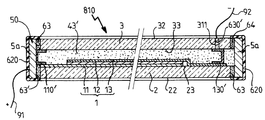
본 발명은 캡슐봉입된 전계 발광 장치(100)에 관한 것으로, 상기 장치는 보호 기판(2)에 위치되고 두 전극(11 내지 13) 사이에 위치되는 활성 전계 발광층(12)을 구비한 전계 발광 시스템(1), 상기 기판에 고정되는 상기 전계 발광층(15)의 보호 덮개, 액상 물 및 수증기에 대한 밀봉 수단, 하나 이상의 부품으로 구성되고 상기 장치의 둘레에 배열되는 보호 장치(50')를 포함하고, 상기 보호 장치(50)는 하나 이상의 금속 부품(5a, 5b) 또는 금속 부분을 포함하는 하나 이상의 유리 또는 플라스틱 부품으로 구성되고, 상기 금속 부품 또는 금속 부분은 적어도 전극 중 하나와 연결되는 제1 전기 연결부로 사용되고; 또는 상기 장치는 전극 중 하나와 연결되는 제1 전기 연결부로서 상기 기판의 측면 에지 중 하나에 또는 상기 보호 덮개의 측면 에지 중 하나에 적층된 하나 이상의 전기 전도층을 포함하고, 상기 전기 전도층은 상기 보호 장치와 상기 기판 또는 상기 보호 덮개 뻗어 있는 것을 특징으로 한다. The present invention relates to a capsule encapsulated electroluminescent device (100) which comprises an electroluminescent system (10) having an active electroluminescent layer (12) located on a protective substrate (2) and positioned between two electrodes (1), a protective cover of the electroluminescent layer (15) fixed to the substrate, sealing means for liquid water and vapor, a protective device (50 ') composed of one or more parts and arranged around the device , The protection device (50) is made up of one or more metal parts (5a, 5b) or one or more glass or plastic parts comprising a metal part, the metal part or metal part being connected to at least one of the electrodes Used as a connection; Or the device comprises at least one electrically conductive layer laminated on one of the lateral edges of the substrate or one of the lateral edges of the protective cover as a first electrical connection to be connected to one of the electrodes, And the protective device and the substrate or the protective cover are extended.
전계 발광층, 적층 중간층, 금속 부품, 기판, 보호 덮개, 발광 시스템, 건조제, 접착제, 밀봉부, 납땜부 An electroluminescent layer, a laminated intermediate layer, a metal part, a substrate, a protective cover, a light emitting system, a drying agent, an adhesive,
Description
본 발명은 캡슐봉입된 발광 장치에 관한 것이다.The present invention relates to a capsule-encapsulated light emitting device.
알려진 바와 같이, 유기 발광 장치(OED), 특히 유기 전계 발광층(유기 발광 다이오드, OLED)에 기초한 발광 다이오드는 산소와 액체 및 수증기 형태의 물에 매우 민감한 전자 구성요소이다.As is known, light emitting diodes based on organic light emitting devices (OED), especially organic electroluminescent layers (organic light emitting diodes, OLEDs), are electronic components that are highly sensitive to oxygen and water and water vapor.
미국 특허공보 US 2002/0068191은 두 전극 사이에 유기 전계 발광층을 포함하는 발광 시스템을 구비한 캡슐봉입된 발광 장치를 개시하고 있다. 상기 유기 전계 발광층은 OLED의 담체 기판이고, 유리와 같은 보호 덮개가 상기 층 아래에 열경화성 에폭시 접착제로 구성된 덮개 접착 박막으로 상기 기판에 밀봉된다. 이러한 장치에는 테두리에 산소 흡수 성분(탈산제)을 포함하는 에폭시 접착제와 둘레를 덮는 및 상기 덮개와 상기 기판의 외부 에지를 덮는 알루미늄으로 구성된 보호 장치가 추가적으로 제공된다. 전기 연결부로 사용되는 두 개의 굽힘형 전도성 스트립이 상기 기판의 에지와 상기 보호 장치 사이에 배열된다. 각 스트립에서, 제1 단부는 (분리가능한 스페이서를 통하여) 접착제 박막에 형성된 홈 내로 삽입되고, 상기 제 1 단부는 연결된 전극에 위치된다. 제2 단부는 상기 장치의 외부 방향으로 뻗어있다. United States Patent Application Publication No. US 2002/0068191 discloses a capsule-encapsulated light emitting device having a light emitting system including an organic electroluminescence layer between two electrodes. The organic electroluminescent layer is a carrier substrate of an OLED and a protective cover such as glass is sealed to the substrate with a laminating adhesive thin film composed of a thermosetting epoxy adhesive under the layer. This device is additionally provided with an epoxy adhesive containing an oxygen absorbing component (deoxidizing agent) at its rim and a protective device covering the periphery and consisting of aluminum covering the lid and the outer edge of the substrate. Two bendable conductive strips, which are used as electrical connections, are arranged between the edge of the substrate and the protective device. In each strip, the first end is inserted into the groove formed in the adhesive film (through the detachable spacer), and the first end is located at the connected electrode. The second end extends outwardly of the device.
본 발명의 목적은 내구성을 잃지 않으면서 또는 심지어 내구성을 향상시키면서 더 간단한 전기 연결 시스템을 가지는 캡슐봉입된 발광 장치를 제공하는 것이고, 특히 심지어 큰 면적을 필요로 하는 (생산 규모, 생산 신뢰성 모두를 용이하게 획득하도록) 산업적 요구 조건에서도 사용가능한 캡슐봉입 발광 장치를 제공하는 것이다. It is an object of the present invention to provide a capsule encapsulated light emitting device having a simpler electrical connection system without losing its durability or even improving its durability and in particular to provide a light emitting device which requires even a large area And to provide a capsule-encapsulated light emitting device that can be used even in industrial requirements.
본 발명의 목적을 달성하기 위하여, 본 발명은:In order to achieve the object of the present invention,
- 보호 기판에 및 두 전극 사이에 위치된 전계 발광 활성층을 포함하는 발광 시스템;A light-emitting system comprising an electroluminescent active layer located on the protective substrate and between the two electrodes;
- 상기 기판에 부착된 상기 활성층을 위한 보호 덮개;A protective cover for said active layer attached to said substrate;
- 액상 물 및/또는 수증기에 대한 밀봉수단;- sealing means for liquid water and / or water vapor;
- 상기 장치의 둘레를 덮는 보호 장치로서, 상기 보호 장치는 하나 이상의 금속 부품 또는 금속 부분을 가지는 하나 이상의 플라스틱 부품 또는 유리 부품으로 구성되고, 상기 금속 부품 또는 상기 금속 부분은 적어도 상기 전극 중 하나에 연결되는 제1 전기 연결부로 사용되는 보호 장치이거나; 또는 상기 장치의 둘레를 덮는 보호 장치로서, 상기 전극 중 하나에 연결되는 제1 전기 연결부로서 상기 기판의 측면 에지 중 하나에 또는 상기 보호 덮개의 측면 에지 중 하나에 적층되고 상기 기판과 상기 보호 장치 사이에 또는 상기 덮개와 상기 보호 장치 사이에 뻗어있는 하나 이상의 전기 전도층 및 하나 이상의 부품으로 구성된 보호 장치;를 포함하는 캡슐봉입된 발광 장치를 제공하는 것이다.The protective device comprising at least one plastic part or glass part having at least one metal part or metal part, the metal part or the metal part being connected to at least one of the electrodes Or a protective device used as a first electrical connection to be made; Or a protection device for covering the perimeter of the device, the device comprising: a first electrical connection connected to one of the electrodes and being laminated on one of the lateral edges of the substrate or one of the lateral edges of the protective cover, And at least one electrically conductive layer extending between the cover and the protection device, and at least one component.
상기 보호 장치를 하나 이상의 전기 연결부로 사용하는 경우, 금속으로 구성되거나 또는 금속 부분을 가지는 보호 장치는 종래 기술과 달리 오버행잉(overhanging) 전도성 스트립의 사용을 제한하거나 또는 심지어 상기 스트립을 전혀 사용하지 않음으로써 연결 지점을 촉진하고, 상기 보호 장치는 또한 내부 전기 연결부가 존재하는 경우 상기 내부 전기 연결부를 보호하고, 그리고 이러한 오버행잉 스트립에 의해 생성된 물을 유도하는 경로를 제한하거나 심지어 제거할 수 있다. When the protective device is used as one or more electrical connections, the protective device, which is made of metal or has a metal part, is different from the prior art in that the use of overhanging conductive strips is limited or even not used at all Which protects the internal electrical connection if there is an internal electrical connection and limits or even removes the path leading to the water produced by such overhanging strip.
또한, 종래 기술에서 접합된 하나 이상의 추가 오버행잉 전도성 스트립을 대체함으로써, 본 발명은 상기 전극 중 하나에 결합된 기판 또는 보호 덮개(하나 이상의 측면 에지 및 외부 에지)를 공지 수단으로 적층된 바람직하게는 박막인 오버행잉 전기 전도층(단일층 또는 다층)으로 코팅하는 방안을 제시한다. 상기 층은 상기 전극 중 하나 또는 상기 전극 중 하나의 일부일 수 있고, 예를 들어 전도성 에나멜일 수 있다. 이러한 구성 배열에서, 상기 보호 장치는 하나의 부품 또는 두 개의 부품으로 구성될 수 있고, 전체적으로 금속으로 구성되거나 또는 바람직하게는 적어도 외부 금속 라이너를 구비한 특히 유리로 형성된 또는 플라스틱으로 형성된 (주로) 유전체일 수 있다.Further, by replacing one or more additional over-hanging conductive strips bonded in the prior art, the present invention provides a substrate or protective cover (one or more side edges and an outer edge) bonded to one of the electrodes, (Single-layer or multi-layer) over-hanging electrically conductive layer which is a thin film. The layer may be one of the electrodes or a part of one of the electrodes, for example a conductive enamel. In such a configuration, the protective device may be composed of one part or two parts and may be composed entirely of metal or preferably of at least an outer metal liner, Lt; / RTI >
이러한 유형의 캡슐봉입을 통하여 극한 기후 조건을 견딜 수 있고, 특히 높은 습도 및/또는 고온을 견딜 수 있고, 충분히 오랜 기간 동안 확실한 보호기능을 가질 수 있다. This type of capsule encapsulation can withstand extreme climatic conditions, especially withstanding high humidity and / or high temperatures, and can have reliable protection for a sufficiently long period of time.
따라서, 본 발명에 따른 캡슐봉입된 발광 장치는 간단하고, 간결하고, 신뢰도가 높고, 내구성이 있으며, 상기 기판 또는 상기 보호 덮개를 파손할 위험 없이 또는 상기 연결부를 손상시킬 위험 없이 용이하게 다루어질 수 있다.Therefore, the capsule-encapsulated light emitting device according to the present invention is simple, compact, reliable, durable and can be handled easily without risk of damaging the substrate or the protective cover, have.
예를 들어, 상기 보호 장치는 설치 프레임(차량 글레이징 유닛인 경우 본체)을 형성할 수 있거나 또는 건물용 양면 글레이징으로 설치될 수 있다.For example, the protective device may form an installation frame (body in the case of a vehicle glazing unit) or may be installed with double-side glazing for buildings.
상기 보호 장치는 (적어도 대부분은) 상기 기판 및 상기 덮개의 둘레를 둘러싸도록 뻗어있다. 상기 보호 장치는 상기 기판과 상기 보호 덮개 사이에 배열되지 않고, 상기 기판의 내면에 고정되지도 않는다. 상기 보호 장치의 조립은 간단하다.The protection device (at least mostly) extends to surround the periphery of the substrate and the cover. The protective device is not arranged between the substrate and the protective cover, and is not fixed to the inner surface of the substrate. Assembly of the protective device is simple.
보호 장치가 상기 발광 시스템의 특성, 예를 들어 상기 기판 및/또는 덮개의 표면을 통한 조명 기능을 방해하지 않기 때문에, 상기 보호 장치는 불투명일 수 있다.The protective device may be opaque because the protective device does not interfere with the characteristics of the light emitting system, for example the illumination function through the surface of the substrate and / or the cover.
상기 보호 장치는, 특히 적층법, 캐스트 수지(cast resin)를 덮음으로써, 또는 상기 기판 및 상기 보호 덮개 사이에 있는 특히 접착제, 에폭시 접착제, 폴리머로 된 밀봉부와 같은 테두리 수단으로 상기 기판을 상기 보호 덮개에 조립하기에 접합하다.The protective device can be used to protect the substrate by means of a laminating process, by covering the cast resin, or by means of a rim, especially between the substrate and the protective lid, such as an adhesive, an epoxy adhesive, Attach to cover to assemble.
본 발명에 따른 보호 장치는 어떠한 유형의 또는 어떠한 기하학적 구조를 가진 장치에도 적절하게 사용될 수 있다. 상기 기판은 특정 형상(직사각형, 라운드형 등)으로 형성될 수 있다. 상기 장치는 어떠한 크기라도 가능하고, 특히 1 ㎡을 초과하는 표면적을 가질 수도 있다.The protective device according to the present invention can be suitably used in any type or apparatus having any geometrical structure. The substrate may be formed in a specific shape (rectangular, round, etc.). The device may be of any size, and in particular may have a surface area of more than 1 m2.
본 발명에 따른 보호 장치는 다양한 가스 유형의 침투로부터, 액체로부터, 또는 먼지로부터 단독 격리 기능 또는 보충적인 격리 기능을 제공하고 및/또는 기계적 강도를 보강한다.The protective device according to the invention provides a sole isolation function or supplemental isolation function from the penetration of various gas types, from liquid or dust, and / or reinforces the mechanical strength.
상기 보호 장치는 중공형 또는 중실형일 수 있고, 곡면형 또는 평면형일 수 있고, 상기 장치의 윤곽, 특히 상기 기판의 측면 에지를 따르거나 따르지 않을 수 있다. 상기 보호 장치는 바람직하게는 내면을 통하여 상기 기판의 측면 에지에 대해 압착되고 상기 조립 수단으로 빠르게 고정됨으로써 둘레를 둘러싸는 부분(측면부라고도 함)을 가질 수 있다.The protective device may be hollow or solid and may be curved or planar and may or may not follow the contours of the device, especially the side edges of the substrate. The protective device may preferably have a peripheral portion (also referred to as a side portion) that is pressed against the side edge of the substrate through the inner surface and quickly fastened to the assembly means.
전체 둘레를 둘러싸기 위하여, 상기 보호 장치의 자유단은 2개 자유단이 하나로 중첩될 수 있거나 또는 맞대기 이음으로 상기 자유단들을 조립하기 위하여 상호 연동하기에 적합한 상보적인 형상을 가질 수 있다. 상기 단부들은 또한 유리 스페이서로 분리될 수 있다.To surround the entire perimeter, the free ends of the protective device may be superimposed in one of two free ends or may have a complementary shape suitable for interlocking to assemble the free ends with butt joint. The ends can also be separated into glass spacers.
상기 보호 장치는 박막일 수 있다. 상기 보호 장치는 바람직하게는 최소 두께가 약 200 ㎛인 알루미늄으로 형성된 하나 이상의 금속 박판으로 구성될 수 있고, 또는 바람직하게는 최소 두께가 약 500 ㎛인 스테인리스 스틸로 구성될 수 있다.The protective device may be a thin film. The protective device may preferably consist of one or more metal foils formed of aluminum having a minimum thickness of about 200 占 퐉 or preferably of stainless steel having a minimum thickness of about 500 占 퐉.
특히 예를 들어 월 레일과 같은 레일에 상기 보호 장치를 부착하기 위하여 상기 보호 장치는 더 두꺼울 수도 있다.In particular, the protective device may be thicker for attaching the protective device to a rail, for example a wall rail.
상기 보호 장치는 두께가 약 1 mm이고 단면이 거의 평행육면체인 평면 섹션 형태일 수 있다. 바람직하게는, 상기 섹션은 낮은 기계적 관성을 가지고, 즉 예를 들어 10 ㎝의 권취반경으로 용이하게 권취될 수 있다.The protective device may be in the form of a planar section having a thickness of about 1 mm and a generally parallelepipedal cross-section. Preferably, the section has low mechanical inertia, i.e. can be easily wound, for example, with a winding radius of 10 cm.
상기 보호 장치는 폴딩 시스템으로 상기 보호 덮개 및 상기 기판 위로 폴딩될 수 있도록 형성(주조, 몰딩, 압출 등)될 수 있다. 따라서, 생산 과정 중에, 예를 들어 금속재와 같은 변환재의 기술 분야에서 통상을 지식을 가진 자에게 주지한 기계를 사용하여 벤딩함으로써 모서리를 보더링(bordering)한다. The protective device may be formed (cast, molded, extruded, etc.) so that it can be folded over the protective cover and the substrate with a folding system. Therefore, during the production process, the edges are bored by bending using a machine known to those skilled in the art, for example, in the art of converting materials such as metal.
상기 보호 장치는 상기 기판 및 상기 보호 덮개를 기계적으로 지지하는 기능을 수행할 정도의 충분한 강성을 가질 수 있다. 이러한 구성 배열에서, 상기 보호 장치의 강성은 보호 장치의 구성 물질의 특성에 의해 한정되고, 상기 보호 장치의 선형 좌굴 강도는 400 N/m 이상이어야 한다. The protective device may have sufficient rigidity to perform the function of mechanically supporting the substrate and the protective cover. In such a configuration, the stiffness of the protective device is limited by the characteristics of the material of the protective device, and the linear buckling strength of the protective device is not to be less than 400 N / m.
상시 보호 장치는 테이프로서 상기 측면 에지 위에 배열될 수 있고, 상기 덮개와 상기 기판에 확실히 접착하는 조립 수단으로 상기 장치의 기계적 조립을 보장한다. The everyday protection device can be arranged on the side edge as a tape and ensures mechanical assembly of the device with the lid and the assembling means that firmly adheres to the substrate.
상기 보호 장치는 복합 재료일 수 있고, 즉 특히 섬유로 선택적으로 보강된 플라스틱 또는 유리로 구성된 하나 이상의 부분과 금속 부분으로 구성되거나 또는 표면에 금속이 입혀진 유리로 구성될 수 있다. 예를 들어, 부틸과 같은 플라스틱은 내부 측벽 및/또는 외부 측벽에서 합성 물질과 선택적으로 혼합된 금속 박막 또는 금속에 기초한 박막을 위한 보강재 역할 및/또는 지지부 역할을 할 수 있다.The protective device may be a composite material, that is to say it may consist of one or more parts made of plastic or glass, in particular reinforced with fibers, and of a metal part or of a glass surface coated with metal. For example, plastic, such as butyl, can serve as a reinforcement and / or a support for thin metal or metal-based thin films selectively mixed with synthetic material on the inner and / or outer side walls.
상기 보호 박막은, 금속에 기초하거나 또는 전체적으로 금속일 수 있고, 특히 수증기에 대한 불침투성을 향상시키기 위해 및/또는 상기 전기 연결부 중 하나를 위해 알루미늄 또는 스테인리스 스틸 스트립 유형이 사용될 수 있다. 이러한 박막의 두께는 예를 들어 2 ㎛ 내지 50 ㎛일 수 있고 또는 그 이상일 수 있다. 게다가, 상기 스트립은 예를 들어 상기 장치가 다루어지고 운송될 때 마모로부터 상기 보호 장치를 보호할 수 있고, 제고 과정 동안 상기 장치가 연화되어야 할 때 열가소성 물질과 열교환을 촉진한다. The protective film may be metal based or metal overall, and aluminum or stainless steel strip types may be used, particularly for enhancing impermeability to water vapor and / or for one of the electrical connections. The thickness of such a thin film may be, for example, from 2 탆 to 50 탆 or more. In addition, the strip can protect the protective device from wear, for example, when the device is handled and transported, and promotes heat exchange with the thermoplastic material when the device is to be softened during the lifting process.
또한, 외부 금속 박막의 폭은 상기 기판 및/또는 상기 보호 덮개의 주 외부 에지를 덮도록 폴딩되기에 또는 내면에 대해 다시 폴딩되기에 충분히 넓다.Also, the width of the outer metal foil is wide enough to fold or to refold the inner surface of the substrate and / or the outer major outer edge of the protective cap.
상기 플라스틱의 에지를 오버행잉하는 단부 중 하나를 가지는 플라스틱의 내면에 위치한 금속 박막은 전기 연결부로 사용될 수 있다.A metal foil located on the inner surface of the plastic having one of the ends over-hanging the edge of the plastic can be used as an electrical connection.
전기 연결부로 사용하기 위하여, 오버행잉되어 있는 내면에 있는 금속 박막을 전도성 조립 수단에 결합시킬 수 있다.For use as an electrical connection, the overlying metal foil on the inner surface can be bonded to the conductive assembly means.
매우 바람직하게는, 상기 플라스틱 보호 장치는 내부에 분말 행태 또는 미립자 형태인 건조제와 결합할 수 있다. 상기 건조제는 분말화된 제올라이트와 같은 분자체일 수 있고, 상기 제올라이트의 비율은 중량 기준으로 20 %까지 또는 부피 기준으로 약 10 %까지 일 수 있다. 상기 건조제의 양은 상기 장치의 용도에 따른 사용 수명의 함수이다. Most preferably, the plastic protective device can be combined with a desiccant in powder form or in particulate form inside. The desiccant may be a molecular sieve such as a powdered zeolite and the proportion of zeolite may be up to 20% by weight or up to about 10% by volume. The amount of desiccant is a function of service life according to the application of the device.
상기 보호 장치 및 상기 보호 장치를 상기 덮개와 상기 기판과 조립하는 수단은 단일 소자를 형성할 수 있고, 상기 단일 소자는 전체적으로 폴리이소부틸렌에 기초한 물질로 구성된 (접착성) 멤브레인, 외부 에지 위에 금속 및 합성 물질로 구성된 박막으로 덮혀 있는 멤브레인을 포함한다. 이러한 구성 배열에서, 오버행잉 층은 바람직하게는 전기 연결부로 선택된다.The means for assembling the protective device and the protective device with the lid and the substrate may form a single element, the single element being a (adhesive) membrane consisting entirely of a material based on polyisobutylene, a metal And a membrane covered with a thin film composed of a synthetic material. In such a configuration, the overlying layer is preferably selected as the electrical connection.
상기 보호 장치는 대부분이 또는 심지어 전체가 금속일 수 있고, 특히 바람직하게는 최소 두께가 약 0.2 mm인 알루미늄으로, 또는 바람직하게는 최소 두께가 약 0.5 mm인 스테인리스 스틸로 구성될 수 있다. The protective device can be composed mostly of aluminum or even entirely of metal, particularly preferably of aluminum having a minimum thickness of about 0.2 mm, or preferably of stainless steel having a minimum thickness of about 0.5 mm.
복합 재료 보호 장치의 금속 보호 장치 또는 금속 스트립은 실외에서의 사용을 위해 자체가 특히 부식 방지 수단으로, 바람직하게는 폴리설파이드 또는 폴리이미드로 덮혀 있을 수 있다.The metal protective device or metal strip of the composite protection device may itself be covered, in particular by means of corrosion protection, preferably with polysulfide or polyimide, for outdoor use.
상기 보호 장치는 평면 기판의 측면 에지 및/또는 보호 덮개의 측면을 통하여 및/또는 상기 (곡면인 또는 평면인) 보호 덮개의 및/또는 기판의 주 외부면의 에지를 통하여 조립될 수 있다.The protective device may be assembled through the side edges of the planar substrate and / or through the sides of the protective cover and / or through the edges of the protective cover (curved or flat) and / or the outer surface of the substrate.
예를 들어, 제조하기 용이한 형태 중 하나로서, 상기 보호 장치의 단면은 U형상일 수 있다.For example, as one of the forms that are easy to manufacture, the cross-section of the protective device may be U-shaped.
바람직한 일 방법으로, 상기 보호 장치는 적어도 부분적으로 상기 기판의 측면 에지를 통하여 및/또는 선택된 평면 보호 덮개의 측면 에지를 통하여 조립된다. 이러한 방법에서, 상기 기판 및/또는 선택된 평면 보호 덮개는 당연히 상기 보호 장치를 지지하기에 충분히 두껍다. 예를 들어, 상기 기판 및/또는 상기 보호 덮개의 두께는 1 mm 내지 10 mm이고, 더 바람직하게는 4 mm 내지 6 mm이다.In a preferred method, the protective device is assembled at least partially through the lateral edge of the substrate and / or through the lateral edges of the selected planar protective cover. In this way, the substrate and / or the selected planar protective sheath are, of course, thick enough to support the protective device. For example, the thickness of the substrate and / or the protective covering is from 1 mm to 10 mm, more preferably from 4 mm to 6 mm.
제조하기 용이한 형태 중에서, 상기 보호 장치의 단면은 직사각형(기판의 측면 에지 및 보호 덮개의 에지로 상기 보호 장치를 지지함) 또는 L형상(기판의 측면 에지 및 보호 덮개의 에지로 상기 보호 장치를 지지함)일 수 있다. Of the forms that are easy to manufacture, the cross-section of the protective device is rectangular (supporting the protective device with the side edge of the substrate and the edge of the protective lid) or L-shaped (the side edge of the substrate and the protective device with the edge of the protective lid ). ≪ / RTI >
상기 조립 수단은 적어도 부분적으로:The assembling means comprises at least in part:
- 접착제, 특히 양면 접착제, 가열에 의해 또는 압력에 의해 또는 냉각에 의해 활성화될 수도 또는 활성화되지 않을 수도 있는 화학 반응으로 부착되는 접착제, 특히 UV 가교결합성 또는 바람직하게는 적외선(IR) 가교결합성 접착제, 예를 들어 에폭시 접착제와 같은 가스 제거 과정 없이 용제를 가지거나 또는 가지지 않는 단일 성분 또는 두 개 성분의 접착제;- adhesives, in particular double-sided adhesives, adhesives which are adhered by chemical reactions which may or may not be activated by heating or by pressure or by cooling, in particular UV crosslinkable or preferably infrared (IR) crosslinkable A single component or two component adhesive with or without a solvent without a degassing process such as an adhesive, for example an epoxy adhesive;
- 폴리설파이드 또는 폴리우레탄 또는 실리콘과 같은 액상 물에 대해 불침투성인 물질로 선택적으로 덮혀 있는, 에틸렌/비닐 아세테이트, 폴리이소부틸렌, 폴리아미드로 구성된 폴리머 군 중 하나 이상 선택된 핫멜트 폴리머에 기초하는 수증기에 대해 불침투성인 물질; - water vapor based on a selected hot melt polymer of one or more of the group of polymers consisting of ethylene / vinyl acetate, polyisobutylene, polyamide, optionally covered with a material that is impermeable to liquids such as polysulfide or polyurethane or silicone A material that is impermeable to water;
- 수증기 및 액상 물에 대해 불침투성이면서 핫멜트 폴리우레탄과 같은 아교 유형의 접착제;Glue type adhesives, such as hot melt polyurethane, impervious to water vapor and liquid water;
- 필요한 경우 초음파로 또는 용접으로 형성되는 하나 이상의 납땜부;으로 구성되거나 또는 상기 수단들 중에서 선택될 수 있다. - at least one soldering portion, which is formed by ultrasonic welding or welding, if necessary, or it can be selected from among these means.
상기 핫멜트 폴리머는 또한 코폴리머 또는 브랜치를 가지는 폴리머 형태일 수 있다. 이러한 3개의 핫멜트 폴리머 군은 특히 다음의 방법 중 두 가지 이상으로 사용되는 것이 바람직하며: 상기 핫멜트 폴리머들은 내부에 뛰어난 밀봉 상태를 제공하고, 상기 핫멜트 폴리머들은 특히 수증기 형태의 물에 대해 뛰어난 불침투성을 제공한다. 상기 접합 수단이 핫멜트 폴리머인 경우, 상기 핫멜트 폴리머는 또한 특히 저 비용으로 제조하기가 용이하며; 상기 핫멜트 폴리머들은 공지의 산업 수단을 통하여 목적하는 장소 내에 액체 행태로 또는 반 액체 형태로 용이하게 주입될 수 있다. 상기 핫멜트 폴리머는 바람직하게는 중량을 기준으로 40% 내지 98%인 밀봉재로 구성된다. 특별히, 상기 핫멜트 폴리머에 특히 3 개의 다른 기능을 가지는 첨가제를 첨가할 수 있다.The hot melt polymer may also be in the form of a polymer having a copolymer or a branch. These three groups of hotmelt polymers are preferably used in more than one of the following ways: the hotmelt polymers provide an excellent seal inside and the hotmelt polymers have excellent impermeability to water, especially water vapor to provide. When the bonding means is a hot-melt polymer, the hot-melt polymer is also particularly easy to manufacture at low cost; The hot melt polymers can be easily injected into a desired location through known industrial means in liquid behavior or semi-liquid form. The hot-melt polymer is preferably composed of a sealant of 40% to 98% by weight. In particular, additives having three different functions can be added to the hot melt polymer.
한편, 예를 들어 이소시아네이트 및/또는 에폭시드 유형의 하나 이상의 가교결합제를 첨가할 수 있다. 또한, 알루미늄 또는 마그네슘 산화물, 규사, 석영, 규토조, 소위 발열성 규토로도 불리는 열성 규토 또는 비발열성 규토로 형성되고, 바람직하게는 분말 형태인 다수의 무기 충전재를 첨가할 수 있다. 또한 상기 무기 충전재들은 활석, 운모 또는 고령토와 같은 규산염, 유리 미소구체 또는 칼슘 탄산염과 같은 다른 무기물 분말 또는 무기물 섬유일 수 있다.On the other hand, for example, one or more cross-linking agents of the isocyanate and / or epoxide type can be added. In addition, aluminum or magnesium oxide, silica, quartz, silica gel, so-called pyrogenic silica It is possible to add a plurality of inorganic fillers which are formed of a heat-resistant or non-heat-resistant silica, preferably in powder form. The inorganic fillers may also be other mineral powders or mineral fibers such as talc, mica or silicates such as kaolin, glass microspheres or calcium carbonate.
마지막으로, 접착성 부여 수지(tackifying resin) 또는 접합 수지(bonding resin)로 알려져 있는 하나 이상의 수지를 첨가할 수 있고, 상기 수지들의 기능은 수지가 접촉해 있는 물질과 밀봉부와의 접착 성능을 향상시키는 것이다. 특히, 상기 수지들은 약 10000인, 특히 5000 이하이거나 또는 500 내지 2000인 매우 낮은 몰질량을 가지고, 바람직하게는 50 내지 130 ℃인, 특히 바람직하게는 90 내지 100 ℃인 연화점을 가지는 화합물일 수 있다. 일 예로서, 포화된 탄화수소에 기초한 지방족 수지를 들 수 있다.Finally, one or more resins known as tackifying resins or bonding resins may be added, and the function of these resins is to improve the adhesion performance of the material with which the resin is in contact with the sealant I will. In particular, the resins may be compounds having a very low molar mass of about 10,000, especially less than 5000, or 500 to 2000, preferably 50 to 130 ° C, particularly preferably 90 to 100 ° C . As an example, saturated aliphatic resins based on hydrocarbons can be mentioned.
명확히 말해서, 상기 밀봉부와 밀봉 대상이 되는 물질 사이의 경계면에 확산 경로가 형성되는 것을 방지하기 위하여 그리고 상기 밀봉부가 층간 분리되는 것을 방지하기 위하여, 내부에 불침투성일 뿐만 아니라 접촉해 있는 물질에 잘 부착되도록 하는 폴리머를 선택하는 것도 중요하다.Specifically, in order to prevent the diffusion path from being formed at the interface between the sealing part and the material to be sealed and to prevent the sealing part from being delaminated, it is not only impermeable to the inside, It is also important to select the polymer to be attached.
또한, 접합제를 사용하는 대신에 또는 접착제를 사용하는 것 외에, 특히 폴리이소부틸렌과 같은 핫멜트 폴리머에 존재하는 몰질량 분산도를 변화시킬 수 있다. 다수의 몰질량을 혼합함으로써, (고 몰질량인 경우에) 온도에 따른 뛰어난 크리프 저항성을 얻을 수 있고, (저 몰질량인 경우에) 밀봉하고자 하는 물질에 우수한 부착성과 우수한 점성(tack)을 획득할 수 있다.Further, in place of or in addition to using a bonding agent, the molar mass dispersion degree present in the hot-melt polymer such as polyisobutylene can be changed. By mixing a large number of molar masses, excellent creep resistance with temperature (in the case of high molar mass) can be obtained and excellent adhesion and tack (tack) to the material to be sealed can do.
종합해 보면, 이러한 핫멜트 폴리머 밀봉부들은 바람직하게는: Taken together, these hot melt polymeric seals are preferably:
- ASTM E 9663 T 표준에 따르면, 3 g/㎡/24h 이하인, 특히 1 g/㎡/24h 이하인 수증기에 대한 침투성(이러한 값은 상기 밀봉부가 물을 거의 침투시키지 않는다는 것을 의미함);- permeability to water vapor of not more than 3 g /
- 70 내지 180 ℃인, 특히 90 내지 100 ℃ 또는 145 내지 170 ℃인 연화점(따라서, 산업적으로 적합한 온도에서 상기 밀봉부를 위치시키기/형성하기 위하여 상기 밀봉부를 액화할 수 있음);A softening point of from 70 to 180 DEG C, in particular from 90 to 100 DEG C or from 145 to 170 DEG C (thus the seal can be liquefied to position / form the seal at an industrially suitable temperature);
- 190 ℃에서 측정시 0.8 내지 8 Pa.s인 점성;을 가진다.And a viscosity of 0.8 to 8 Pa.s measured at 190 < 0 > C.
바람직하게는, 필요한 경우, 전술한 밀봉부는, 특히 액상 물에 대하여 밀봉 성능을 보충한다는 의미의 "보충적인" 하나 이상의 다른 밀봉부에 결합될 수 있다. 따라서, 상기 보충적인 밀봉부는, 폴리설파이드, 폴리우레탄 또는 실리콘 유형의 제2 밀봉부일 수 있고, 상기 제2 밀봉부는 공지의 방식으로 상기 제1 밀봉부를 코팅함으로써 또는 공유 압출 성형 및/또는 상기 두 밀봉부의 동시 압출 성형을 통하여 상기 제1 밀봉부에 대해 위치될 수 있다.Preferably, if desired, the seals described above may be joined to one or more other seals which are "complementary ", in particular meant to complement the sealing performance against the liquid material. Thus, the supplemental seal may be a second seal of polysulphide, polyurethane or silicon type, and the second seal may be formed by coating the first seal in a known manner or by coextrusion and / Can be positioned relative to the first seal through co-extrusion.
특히 액상 물에 대해 밀봉 상태를 형성하기 위하여:In particular, to form a sealed state for the liquid material:
- 폴리우레탄(PU) 또는 특정 열가소성 엘라스토머(TPE) 폴리머의 압출 성형으로;By extrusion of a polyurethane (PU) or a specific thermoplastic elastomer (TPE) polymer;
- PU의 반응성 사출 성형(RIM)으로; - reactive injection molding (RIM) of PU;
- PVC(폴리비닐 클로라이드)/TPE 혼합물의 열가소성 사출 성형으로;- thermoplastic injection molding of PVC (polyvinyl chloride) / TPE mixture;
- 에틸렌-프로필렌-디엔 모노머(EPDM) 3량체의 사출 성형 및 가황으로; 액상 물에 대해 불침투성인 조립 수단을 덮는 밀봉부를 형성할 수 있다.- injection molding and vulcanization of ethylene-propylene-diene monomer (EPDM) trimer; It is possible to form the sealing portion covering the assembling means impermeable to the liquid material.
특히, 공기 중의 습기에 가교결합될 수 있고 액상 물 및 수증기 모두에 대해 우수한 불침투성을 확실히 가지는 폴리우레탄에 기초한 핫멜트 접착제 유형의 접착제가 바람직하다. 상기 접착제의 수증기 형태의 물에 대한 침투성은 일반적으로 3 g/㎡/24h 이하이고, 심지어 2 g/㎡/24h에 가깝다.In particular, adhesives of the hotmelt adhesive type based on polyurethane, which can be crosslinked to moisture in air and have good impermeability to both liquid water and water vapor, are preferred. The permeability of the adhesive in water vapor form to water is generally less than 3 g /
또한 당연히, 상기 접착제는 바람직하게는 액상 물에 의한, 자외선 광선에 의한 그리고 일반적으로 전단 응력이라고도 불리는 글레이징 유닛의 표면에 수직방향으로 가해질 수 있는 인발력에 의한 그리고 글레이징 유닛의 하중 방향의 힘에 평행하게 가해지는 인발력에 의한 분리 현상(debonding)을 견딜 수 있어야 한다. 만족스러운 접찹제는 바람직하게는 0.45 MPa 이상의 인열 강도(tear strength)를 가져야 한다.It is of course also possible that the adhesive is preferably applied to the surface of the glazing unit by means of a liquid material, by means of a pulling force which can be applied perpendicularly to the surface of the glazing unit, also referred to as ultraviolet light and generally referred to as shear stress, It should be able to withstand the debonding caused by the applied pulling force. The satisfactory adhesives should preferably have a tear strength of at least 0.45 MPa.
바람직하게는, 상기 접착제는 신속한 접합 성능을 가질 수 있고, 즉 약 수 초 내에 접합시킨다. 상기 접착제의 접착은 또한 전기 연결부를 검사할 수 있도록 또는 심지어 상기 전기 연결부를 재검사할 수 있도록 매우 느리게 진행될 수도 있다. Preferably, the adhesive can have fast bonding performance, i.e., bonds within a few seconds. Adhesion of the adhesive may also proceed very slowly to allow inspection of the electrical connections or even to retest the electrical connections.
조립 수단의 수증기 침투성 계수는 바람직하게는 5 g/㎡/24h 미만일 수 있고, 더 바람직하게는 1 g/㎡/24h 미만일 수 있다.The water vapor permeability coefficient of the assembly means may preferably be less than 5 g /
상기 조립 수단은:The assembling means comprises:
- 상기 덮개의 또는 상기 덮개를 상기 기판에 조립하는 테두리 수단의 밀봉 성능; 및/또는,Sealing performance of the lid or rim means for assembling the lid to the substrate; And /
- 상기 보호 장치와 덮개 또는 테두리 수단 사이를 밀봉하는 추가 물질의 존재 여부 및/또는 건조제의 존재 여부;에 따라 선택될 수 있다.- the presence of additional material to seal between the protective device and the lid or rim means and / or the presence or absence of a desiccant.
상기 조립 수단은 전기 절연체로 선택될 수 있고, 이때 상기 조립 수단의 전기 전도계수는 바람직하게는 10-4 ohm-1.cm-1 미만이다.The assembly means may be selected as an electrical insulator, wherein the electrical conductivity coefficient of the assembly means is preferably less than 10 -4 ohm -1. Cm -1 .
다른 방법으로, 특히 상기 보호 장치를 통한 전기 연결부를 용이하게 하기 위하여, 상기 금속 부품 또는 상기 금속 부분은 적어도 부분적으로, 상기 장치의 둘레 대부분에 걸쳐 있는 또는 둘레 전체에 걸쳐 있는 상기 보호 덮개의 또는 상기 기판의 주 외부 에지에 걸쳐 있는, 납땜부, 용접부, 전도성 접착제, 특히 은이 충전된 에폭시 유형의 접착제와 같은 조립 수단 중 하나 이상 선택된 전도성 조립 수단으로 조립된다. Alternatively, in order to facilitate the electrical connection, in particular through the protective device, the metal part or the metal part may at least partly be provided on the protective cover or over the entire circumference of the device, Assembly means, such as solder, welds, conductive adhesive, especially silver-filled epoxy type adhesive, which spans the main outer edge of the substrate, is assembled with the selected conductive assembly means.
이를 위하여, 상기 장치는 상기 연결부(들)로서 이하에서 기술할 (결합되는 또는 대체적인) 특징부들 중 하나 이상을 포함할 수 있다.To this end, the device may comprise one or more of the following (combined or alternative) features as the connection (s).
적어도 제1 전기 연결부를 위하여, 그리고 바람직하게는 전기 연결부들 각각을 위하여, 상기 장치는 상기 보호 장치에 접합된 다음의 전기 연결 수단 중 하나 이상 선택된 바람직하게는 박막인, 내부 전기 연결 수단을 포함하고, 상기 전기 연결 수단은:The device comprises an internal electrical connection means, preferably at least one of which is selected from one or more of the following electrical connection means bonded to the protective device, for at least the first electrical connection, and preferably for each of the electrical connections , Said electrical connection means comprising:
- 예를 들어 구리, 금, 은, 알루미늄 또는 텅스텐으로 구성된 금속 전선과 같은 하나 이상의 전기 전도성 전선;One or more electrically conductive wires, such as, for example, metallic wires composed of copper, gold, silver, aluminum or tungsten;
- 선택적으로 더 나은 전류 분산을 위하여 상기 기판의 또는 상기 보호 덮개의 주 내부 에지를 따라 뻗어있는, 예를 들어 두께가 약 50 ㎛ 내지 100 ㎛인 호일 유형의 금속 스트립과 같은 하나 이상의 선택적인 (자가) 접착성 전기 전도성 스트립;- optionally one or more optional electrodes, such as foil-type metal strips of thickness about 50 [mu] m to 100 [mu] m, extending along the main inside edge of the substrate or the protective cover for better current spreading ) An adhesive electrically conductive strip;
- 은 또는 구리 유형의 금속 (나노) 입자들이 충전된 잉크젯으로 적층된 선택적 접합 물질로 구성된 거품 형태의 전기 전도성 충전재;An electrically conductive filler in the form of a foam consisting of an optional adhesive material laminated with an ink jet filled with metal (nano) particles of silver or copper type;
- 더 나은 전류 분산을 위하여 바람직하게는 상기 기판의 또는 상기 덮개의 주 내부 에지를 따라 선택적으로 뻗어있는, 두께가 약 10 ㎛ 내지 100 ㎛인 전기 전도성 에나멜;- electrically conductive enamel, preferably about 10 [mu] m to 100 [mu] m thick, which optionally extends along the main inner edge of the substrate or the cover for better current spreading;
- 예를 들어 은이 충전된 에폭시 접착제와 같은 전기 전도성 접착제;Electroconductive adhesives, such as, for example, silver filled epoxy adhesives;
- 선택적으로 하나 이상의 조립 납땜부를 연장하는 하나 이상의 납땜부;이다. - at least one soldering portion optionally extending one or more assembled soldering portions.
공지된 한 호일은 두께가 50 내지 100 ㎛이고 폭이 1 내지 100 mm, 바람직하게는 3 내지 5 mm인 구리로 구성된 박막 스트립이다. 상기 구리 스트립은 부식을 제한하고 전기 접촉을 용이하게 하기 위하여 예를 들어 주석에 기초한 또는 주석/납 합금에 기초한 주석 도금으로 또는 납땜부로 덮혀 있다.A known foil is a thin film strip composed of copper having a thickness of 50 to 100 占 퐉 and a width of 1 to 100 mm, preferably 3 to 5 mm. The copper strips are covered with, for example, tin-based or tin-lead-based tin plating or brazed parts to limit corrosion and facilitate electrical contact.
상기 보호 장치를 통하여 전기 연결부를 단순화하기 위하여, 상기 장치는 적어도 제1 전기 연결부로서 상기 기판의 또는 상기 보호 덮개의 하나 이상의 측면 에지까지 뻗어있는 내부 연결 수단을 포함할 수 있고, 상기 내부 연결 수단은:In order to simplify the electrical connection through the protective device, the device may comprise at least a first electrical connection, an inner connection means extending to one or more lateral edges of the substrate or the protective cover, :
- 호일 유형의 전기 전도성 스트립;Electroconductive strips of the foil type;
- 전기 전도성 에나멜;- electrically conductive enamel;
- 전기 전도성 접착제;- electrically conductive adhesives;
- 선택적으로 투명한 박막인 (단일층 또는 다층인) 전기 전도층;으로 구성되거나 중 하나에서 선택되고, - an electrically conductive layer (which is a single layer or a multilayer) which is optionally a transparent thin film;
상기 수단들은 바람직하게는 상기 보호 덮개의 또는 상기 기판의 측면 에지를 통하여 조립하는 납땜부와 및/또는 특히 상기 보호 덮개 또는 상기 기판의 측면 에지를 조립하는 납땜부 아래에서 상기 전극 중 하나로부터 뻗어있는 부분과 결합된다.Said means preferably comprise a soldering portion which is assembled through the side edge of said protective cover or said substrate and / or a soldering portion which extends from one of said electrodes under the soldering portion, in particular assembling the side edge of said protective cover or said substrate ≪ / RTI >
반대로 말해면, 상기 기판에 추가된 나머지 전극은 상기 기판의 주 내면까지는 뻗어 있지 않을 수 있다.In other words, the remaining electrodes added to the substrate may not extend to the main inner surface of the substrate.
일 특징에 따르면, 상기 전극 중 하나는 상기 기판의 또는 상기 보호 덮개의 가능한 경우 반대쪽에 위치하는 양 에지까지 뻗어 있는 두 부분을 포함할 수 있고, 상기 두 부분 중 한 부분은 (특정 기계적, 화학적 또는 레이져 처리 수단에 의해) 나머지 전극의 전기 연결부로 사용되도록 뻗어 있는 나머지 부분으로부터 전기적으로 절연되도록 뻗어 있다.According to one aspect, one of the electrodes may comprise two parts extending to both edges of the substrate or possibly opposite sides of the protective covering, where one of the two parts is of a specific mechanical, (By means of laser processing means) from the remainder extending to be used as the electrical connection of the remaining electrode.
상기 보호 장치는 적어도 별개의 전기 연결부로 사용되는 금속에 기초한 두 개의 부품으로 구성될 수 있고, 상기 부품들은 하나 이상의 다음 수단에 의해 부착되고 전기적으로 절연되며, 상기 수단은:The protective device may be composed of two parts based on metal which are used as at least separate electrical connections and the parts are attached and electrically insulated by one or more of the following means:
- 폴리설파이드 또는 폴리우레탄 또는 실리콘과 같은 액상 물에 대해 불침투성인 물질로 선택적으로 덮혀 있는, 에틸렌/비닐 아세테이트, 폴리이소부틸렌, 폴리아미드로 이루어진 폴리머 군 중 하나 이상 선택된 핫멜트 폴리머에 기초한 물질;A material based on at least one selected from the group of polymers consisting of ethylene / vinyl acetate, polyisobutylene, polyamide, optionally covered with a material that is impermeable to liquid water such as polysulfide or polyurethane or silicone;
- 폴리우레탄과 같은 핫멜트 아교 유형인 수증기 및 액상 물에 대해 불침투성인 접착제;이다.- adhesives that are impermeable to water vapor and liquids, such as hot melt glue types such as polyurethane.
바람직하게는, 상기 비전도성 조립 수단과 동일한 수단이 선택될 수 있다.Preferably, the same means as the non-conductive assembly means can be selected.
또한, 상기 보호 장치는 상기 제1 연결부로 사용되는 금속에 기초한 단일 부품일 수 있고, 바람직하게는 제2 전기 연결부는 선택된 유전체 덮개에 형성된 관통구에 의해 형성되고, 상기 관통구는 납땜부 및/또는 다른 전기 전도성 물질(거품 등)로 충전된다. 상기 관통구의 크기는 약 5 mm일 수 있다. The protection device may be a single part based on the metal used as the first connection part, and preferably the second electrical connection part is formed by a through-hole formed in the selected dielectric cover, and the through- It is filled with other electrically conductive materials (such as foam). The size of the through-hole may be about 5 mm.
게다가, 덮고 있는 금속 필렛이 상기 관통구 둘레에 용접될 수 있다.In addition, a covering metal fillet can be welded around the through-hole.
하부 전극이라고도 불리는 전극은 상기 기판에 가장 가까이 위치되어 있고(또는 전도성 기판의 실질적 부품이고), 상부 전극이라고 불리는 전극은 상기 기판에서 가장 멀리에 위치되어 있다.An electrode, also referred to as a lower electrode, is located closest to the substrate (or is a substantial part of the conductive substrate) and an electrode called the upper electrode is located furthest away from the substrate.
상기 덮개는 상기 층을 둘러싸는 테두리 수단이라고 불리는 것에 의해 또는 덮개 수단이라고 불리는 것에 의해 (열가소성 박판 유형의 적층 중간층에 의한, 에폭시 유형의 캐스트 수지 등에 의한) 활성 시스템 위에서 상기 기판에 부착될 수 있다.The lid can be attached to the substrate on an active system (referred to as the rim means surrounding the layer or by means of lid means) (by means of a laminated intermediate layer of the thermoplastic lamina type, by epoxy type cast resin or the like).
간격 형성 수단 또는 테두리 연결 수단은 (오염, 합선의 위험 등으로)발광 시스템이 손상되는 것을 방지할 수 있고 배열하기가 용이할 수 있고 및/또는 경제적일 수 있다. 상기 테두리 수단은 또한 상기 덮개가 평면인 경우 상기 보호 덮개가 상기 시스템과 접촉하는 것을 방지할 수 있다.The spacing means or rim connection means can prevent damage to the luminous system (due to contamination, short circuit, etc.) and can be easy to arrange and / or economical. The rim means may also prevent the protective cover from contacting the system when the lid is flat.
상기 테두리 수단은:The rim means comprise:
- 접착제, 예를 들어 Addision Clear Wave사의 공업용 접착제 AC-A1438 또는 Nagase사의 접착제 XNR4416L과 같은 UV 경하성 접착제, 또는 적외선(IR) 경화성 접착제, 예를 들어 에폭시 접착제 또는 아크릴 접착제와 같은 단일 성분 또는 두 개의 성분의 무-용제(solvent free) 접착제;- adhesives, for example UV light-curable adhesives, such as Industrial Adhesive AC-A1438 from Addision Clear Wave or Adhesive XNR4416L from Nagase, or infrared (IR) curable adhesives such as epoxy adhesives or acrylic adhesives, Solventless adhesive of the component;
- 지지 표면에 접착제를 가지는 유리 스페이서; 또는,A glass spacer having an adhesive on the support surface; or,
- 용해된 글래스 프릿;일 수 있다.- dissolved glass frit;
바람직하게는, 상기 테두리 수단은 액상 물에 대해 불침투성일 수 있고, 특히 바람직하게는 수증기에 대해 불침투성일 수 있고, 더 바람직하게는 글래스 프릿일 수 있다.Preferably, said rim means may be impermeable to liquid matter, particularly preferably impermeable to water vapor, more preferably glass frit.
상기 테두리 수단은:The rim means comprise:
- 상기 보호 장치 및 상기 조립 수단의 밀봉 성능;The sealing performance of said protective device and of said assembling means;
- 상기 보호 장치와 상기 테두리 수단 사이에 건조제 또는 다른 불침투성 물질이 존재하는지 여부;Whether a drying agent or other impermeable material is present between said protective device and said rim means;
- (연속적으로 또는 단계적으로 실행되는) 상기 장치를 제조하는 방법;에 따라 선택될 수 있다.- the method of manufacturing the device (which is carried out continuously or stepwise).
상기 테두리 수단의 위치는 당연히 면적과 상기 기판에서의 활성층의 배열과 상기 보호 덮개의 크기에 따라 결정된다. 상기 테두리 수단은 주 에지들 또는 상기 보호 덮개의 중심에 가장 가까운 에지들을 덮고 있을 수 있다.The position of the rim means is naturally determined by the area, the arrangement of the active layers in the substrate and the size of the protective cover. The rim means may cover the major edges or the edges closest to the center of the protective cover.
상기 장치는 또한 적층된 글레이징 유닛을 형성할 수 있다. 적층된 글레이징 유닛은 일반적으로 두 개의 강성 기판으로 구성되고, 상기 기판들 사이에는 열가소성 폴리머 박판 또는 상기 박판들이 중첩되어 형성된 구성부가 위치될 수 있다. 또한, 본 발명은 다수의 보호 폴리머 박판과 결합한 유리 유형의 단일 강성 보호 기판을 사용하는 "비대칭" 적층 글레이징 유닛이라고 알려져 있는 구성요소를 포함한다. The apparatus can also form a laminated glazing unit. The laminated glazing unit is generally composed of two rigid substrates, and between the substrates a thermoplastic polymer thin plate or a constituent part formed by overlapping the thin plates may be located. The present invention also includes a component known as an "asymmetric" laminated glazing unit using a single rigid protective substrate of glass type combined with a plurality of protective polymer foils.
또한, 본 발명은 엘라스토머 유형의 단일면 또는 양면 접착성 폴리머에 기초한 하나 이상의 중간층 박판을 가지는 적층된 글레이징 유닛을 포함한다.(즉 종래 기술의 적층 작업을 필요로 하지 않음, 즉 열가소성 중간층 박판을 연화시키고 접착시키기 위하여 일반적으로 압력을 받도록 가열을 요구하는 적층 과정을 필요로 하지 않음)The present invention also encompasses a laminated glazing unit having at least one intermediate layer laminate based on an elastomeric type single-sided or double-sided adhesive polymer (i. E. It does not require prior art laminating operations, i.e. softening the thermoplastic, Lt; RTI ID = 0.0 > and / or < / RTI &
이러한 구성 배열에서, 덮개 및 기판을 부착하는 수단은 이때 적층 중간층일 수 있고, 특히 열가소성 물질로 된 박판일 수 있고, 예를 들어 폴리우레탄(PU) 또는 폴리비닐 부티랄(PVB) 또는 에틸렌/비닐 아세테이트(EVA) 또는, 열 경화성(에폭시, PU) 또는 자외선 경화성(에폭시, 아크릴 수지)인 단일 성분 수지 또는 다중 성분 수지일 수 있다. 바람직하게는, 상기 덮개 및 기판을 부착하는 수단은 상기 보호 덮개 및 상기 기판과 크기가 동일하다.In such a configuration, the lid and the means for attaching the substrate can then be a laminated intermediate layer, in particular a thin sheet of thermoplastic material, such as polyurethane (PU) or polyvinyl butyral (PVB) or ethylene / vinyl acetate (EVA) or a single component resin or a multi-component resin that is thermosetting (epoxy, PU) or ultraviolet curable (epoxy, acrylic resin). Preferably, the lid and the means for attaching the substrate are the same size as the protective lid and the substrate.
상기 적층 중간층은 특히 큰 장치에서, 예를 들어 면적이 0.5 ㎡을 초과하는 장치에서 상기 보호 덮개가 구부려지는 것을 방지할 수 있다. The laminated interlayer can prevent the protective cover from bending, especially in large apparatuses, for example, in devices having an area exceeding 0.5 m < 2 >.
특히, EVA는:Specifically, EVA:
- 부피를 기준으로 물을 거의 포함하지 않거나 전혀 포함하지 않는다는 점;- contains little or no water on a volume basis;
- EVA를 가공하기 위해서는 고압이 필요하지 않다는 점;과 같은 많은 장점을 제공한다.- It does not require high pressure to process EVA.
더 용이하게 실행될 수 있고 더 경제적이고 가능한 경우 더 불침투성이기 때문에, 열가소성 적층 중간층은 캐스트 수지로 구성된 덮개부에 바람직할 수 있다.The thermoplastic laminated intermediate layer may be preferred for the lid portion made of cast resin, because it can be performed more easily and is more economical and, if possible, more impermeable.
상기 중간층은 선택적으로 전기 전도성 전선망 및/또는 전기 전도층 또는 상기 내면에서 전기 전도 스트립을 포함하고, 상기 전선망은 상기 내면에 설치되며 하나의 전극과 접촉한다.The intermediate layer optionally comprises an electrically conductive wire network and / or an electrically conductive layer or an electrically conductive strip on the inner surface, wherein the wire network is disposed on the inner surface and contacts one electrode.
그리고 후자의 설계에서, 상기 장치는 바람직하게는 상기 전극들 중 하나 또는 나머지 하나에 연결된 다음의 전기 연결 수단들 중 하나를 포함하고, 상기 전기 연결 수단들은:And in the latter design, the device preferably comprises one of the following electrical connection means connected to one or the other of the electrodes, said electrical connection means comprising:
- (바람직하게는 열가소성 물질을 연화함으로써) 상기 적층 중간층의 하나 이상의 에지에 고정되고, (바람직하게는 납땜으로) 금속 보호 장치의 내부 측벽과 접촉하는 호일 유형의 특히 U형상인 전기 전도성 스트립;An electrically conductive strip in the form of a foil of a particularly U-shape that is secured to at least one edge of the laminate intermediate layer (preferably by softening the thermoplastic) and contacts the inner sidewall of the metal protective device (preferably by soldering);
- (바람직하게는 납땜으로) 상기 전극에 접합된 제1 단부와, 유전체 덮개의 금속 물질로 충전된 관통구와 접촉하는 제2 단부와, 상기 두 단부 사이에 절개되어 상기 중간층을 관통하는 부분을 가지는 전기 전도성 스트립;이다.- a first end bonded to the electrode (preferably by brazing), a second end in contact with a through-hole filled with a metallic material of the dielectric sheath, and a portion cut between the two ends to penetrate the intermediate layer Electrically conductive strip;
상기 테두리 수단 또는 덮개 연결 수단은 단기간 동안 충분히 불침투성이고, 상기 수단들로 인해 밀봉된 장치를 저장할 수 있고 및/또는 수송할 수 있다. 명확히 말해서, 상기 보호 장치의 조립 과정이 상기 시스템이 생산되는 장소에서 실행되어야만 하는 것은 아니고 또는 이러한 조립 과정은 유연성을 가지도록 제조하기 위해 지연될 수 있다.The rim means or lid connecting means are sufficiently impermeable for a short period of time and can store and / or transport the sealed device by means. Specifically, the assembly process of the protective device does not have to be carried out in the place where the system is produced, or the assembly process can be delayed to make it flexible.
상기 완성된 장치가 연속적으로 생산될 때, 상기 보호 장치가 조립시 충분한 보호 경계를 갖춘다면 특히 수증기에 대해 불침투성인 연결 수단 및/또는 건조제를 제공할 필요가 없다. 이러한 경우에, 테두리 유형의 연결 수단은 상기 기판과 상기 덮개 사이에 스페이서 역할을 한다.When the finished device is produced continuously, it is not necessary to provide a connection means and / or desiccant which is impermeable to water vapor, especially if the protective device has sufficient protective boundary at the time of assembly. In this case, the rim type connecting means serves as a spacer between the substrate and the cover.
본 발명에 따른 장치는 바람직하게는 상기 기판에 위치된 건조제를 포함할 수 있고, 상기 건조제는 테두리 수단의 외부 에지에 또는 심지어 덮개 수단의 외부 에지에 위치될 수 있고 및/또는 상기 수단에 혼합될 수 있다. The device according to the invention may preferably comprise a desiccant located on said substrate, said desiccant being located at the outer edge of the rim means or even at the outer edge of the lid means and / .
따라서, 이렇게 위치된 경우, 밀봉부를 둘러싸는 건조제의 양은 소량이다. 상기 건조제는 물 유도 경로에 위치되고, 셋 백(set back) 테두리 수단 또는 덮개 연결 수단에 최대한 가까이에 위치된다. 발광 시스템이 양면에서 발광하는 구성 배열인 경우, 상기 건조제는 투명 건조제보다 저가인 불투명 건조제일 수 있다.Thus, when so positioned, the amount of desiccant surrounding the encapsulation is small. The desiccant is located in the water induction path and is located as close as possible to the set back rim means or cover connecting means. In the case of a configuration in which the light emitting system emits light on both sides, the desiccant may be a less opaque drying agent than a clear desiccant.
상기 건조제는 테이프일 수 있고, 특히 접착성 테이프일 수 있거나, 또는 칼슘 산화물 또는 다른 알칼리 또는 알칼리토류 금속과 같은 분말일 수 있다. 상기 분말은 바람직하게는 상기 보호 장치의 압력 및 선택적으로 에지 충전재의 압력으로 압축된다. 이러한 압축으로 인해 건조제의 건조 성능을 더 향상시킬 수 있다.The desiccant may be a tape, in particular an adhesive tape, or may be a powder such as calcium oxide or other alkaline or alkaline earth metals. The powder is preferably compressed to the pressure of the protective device and optionally to the pressure of the edge filler. This compression can further improve the drying performance of the desiccant.
상기 보호 덮개가 평면이고 상기 보호 덮개의 크기가 상기 기판의 크기보다 작은 경우, 상기 건조제의 위치를 정하기 위하여 예를 들어 두께가 약 3 mm인 후막 덮개를 선택할 수 있다.If the protective lid is flat and the size of the protective lid is smaller than the size of the substrate, a thick film lid having a thickness of, for example, about 3 mm may be selected to position the desiccant.
상기 보호 덮개가 평면이고 상기 보호 덮개의 크기가 상기 기판의 크기와 거의 동일한 경우, 상기 건조재의 위치를 정하기 위하여 예를 들어 베벨이 형성된 에지와 같은 점점 가늘어지는 테두리 영역을 가지는 후막 덮개를 선택할 수 있다. If the protective lid is flat and the size of the protective lid is approximately the same as the size of the substrate, a thick film lid having a tapered rim area, such as, for example, beveled edges, may be selected to position the lid .
게다가, 상기 장치는 상기 보호 장치와 상기 덮개 또는 테두리 수단 사이에 비드 또는 밀봉부를 형성하는 충전재를 포함할 수 있다.In addition, the device may comprise a filler which forms a bead or seal between the protective device and the lid or rim means.
상기 충전재는 :Said filler comprising:
- 접착성 (특히 무-용제(solvent free) 접착성);- adhesiveness (especially solvent-free adhesiveness);
- 수증기 형태인 물에 대한 불침투성;Impermeability to water in the form of water vapor;
- 비전도성;과 같은 성질 중 하나를 가질 수 있다.- nonconductivity; and the like.
수증기 형태의 물에 대해 불침투성인 밀봉부는 바람직하게는 부착 수단을 위해 특히 앞서 언급한 3개의 폴리머 군 중 하나 이상 선택된 핫멜트 폴리머에 기초할 수 있다. Seals that are impermeable to water vapor form water may preferably be based on the hotmelt polymer selected for one or more of the above-mentioned three polymer families, especially for the attachment means.
바람직하게는, 충전재의 전기 전도도는 적어도 10-4 ohm-1.cm-1 미만, 특히 10-5 ohm-1.cm-1미만, 그리고 심지어 (필요한 경우 상기 조립 수단과 같이 선택적으로) 10-7ohm-1.cm-1 또는 10-9 ohm-1.cm-1 미만이다. 주로 전기 절연성인 밀봉부를 선택함으로써, 상기 밀봉부를 통한 일 전기 전도층에서 또 다른 전기 전도층으로의 합선의 위험이 확실히 제거될 수 있다. 예를 들어, 유럽 특허공개공보 EP 0 836 932에 개시된 밀봉부를 선택할 수 있다. 상기 밀봉부는, 열가소성 또는 열경화성 폴리머에 기초한, 바람직하게는 엘라스토머(A)에 기초한, 특히 이소부틸렌 또는 에틸렌-프로필렌과 같은 모노올레핀에 기초한 또는 메탈로센 촉매로 촉진된 폴리올레핀에 기초한 또는 에틸렌/비닐 아세테이트(EVA)에 기초한 또는 에틸렌/비닐 부티레이트(EVB)에 기초한 또는 실리콘 또는 폴리우레탄에 기초한 고무들 중에서 선택된 포화된 탄화수소에 기초한 엘라스토머 유형의 엘라스토머에 기초한, 폴리머 매트릭스로 구성된 밀봉부이다. Preferably, the electrical conductivity of the filler is at least 10 -4 ohm -1. Cm -1 , especially less than 10 -5 ohm -1 cm -1 , and even 10 - 7 ohm -1 cm -1 or It is less than 10 -9 ohm -1 .cm -1. By choosing a seal that is primarily electrically insulating, the risk of short circuits from one conductive layer to another via the seal can be reliably eliminated. For example, the seal disclosed in EP 0 836 932 can be selected. The seal may be based on a thermoplastic or thermosetting polymer, preferably based on a elastomer (A), especially based on a monoolefin such as isobutylene or ethylene-propylene, or on a metallocene catalyzed polyolefin or ethylene / vinyl Based on elastomers of the elastomer type based on saturated hydrocarbons based on ethylene (EVA) or based on ethylene / vinyl butyrate (EVB) or on silicon or polyurethane based rubbers.
이러한 유형의 밀봉부는 특히 이소시아네이트 또는 에폭시드 유형의 가교제를 사용하여 부분적으로 또는 전체적으로 가교결합될 수 있다. 바람직하게는, 밀봉부는 엘라스토머에 기초한 폴리머이다. 명확하게 말해서, 엘라스토머에 기초한 폴리머의 유리 전이 온도는 통상적인 사용 온도보다 현저히 낮고, 상기 엘라스토머에 기초한 폴리머는 압출 성형 기술과 같은 정밀하게 제어된 자동 기술을 사용하여 활성 글레이징 유닛 내에 결합될 수 있는 특성을 가지며, 특히 유리 기판과 같은 기판에 우수한 접착성을 나타내기 때문에, 상기 엘라스토머에 기초한 폴리머 유형의 폴리머가 바람직하다.This type of seal can be cross-linked in part or in whole, in particular using isocyanate or epoxide-type cross-linking agents. Preferably, the seal is a polymer based on an elastomer. Clearly speaking, the glass transition temperature of the elastomer-based polymer is significantly lower than the typical operating temperature, and the polymer based on the elastomer is capable of being combined in the active glazing unit using precisely controlled automatic techniques such as extrusion techniques , And polymers of the polymer type based on the above-described elastomers are preferred, in particular, because they exhibit excellent adhesion to substrates such as glass substrates.
예를 들어, 상기 엘라스토머에 기초한 폴리머에서 바람직한 엘라스토머는 포화된 탄화수소에 기초한 폴리머들 (탄화수소에 기초한 폴리머, 실리콘) 중에서 선택된, 바람직하게는 이소부틸렌 또는 에틸렌-프로필렌과 같은 모노올레핀에 기초한 폴리머 또는 특히 폴리에틸렌 유형의 메탈로센 촉매로 촉진된 폴리올레핀 중에서 선택된 엘라스토머이다. For example, the preferred elastomer in the polymer based on the elastomer is selected from polymers based on saturated hydrocarbons (polymers based on hydrocarbons, silicon), preferably based on monoolefins such as isobutylene or ethylene-propylene, Lt; RTI ID = 0.0 > polyolefin < / RTI > promoted with a metallocene catalyst of the polyethylene type.
또한, 폴리에틸렌, 에틸렌/프로필렌 코폴리머, 에틸렌/프로필렌/부틸렌 코폴리머, 폴리메틸펜틴, 프로필렌, 이소부틸렌/이소프렌, 에틸렌/비닐 아세테이트(EVA) 또는 에틸렌/비닐 부티레이트(EVB) 유형의 폴리올레핀도 사용될 수 있다. 또한, 폴리우레탄 군의 폴리머 또는 상기한 바와 같이 실리콘 군의 폴리머를 사용할 수 있고, 더 바람직하게는 단위(모티프를 나타냄)를 가지는 폴리머들을 사용할 수 있으며: 여기서, R1와 R2는 특히 염소 유형의 할로겐, 메틸기 또는 에틸기와 같은 포화 유형의 탄화수소 라디칼, 또는 페놀과 같은 방향족 유형의 탄화수소 라디칼 또는 수소일 수 있다. Polyolefins of the type of polyethylene, ethylene / propylene copolymer, ethylene / propylene / butylene copolymer, polymethylpentine, propylene, isobutylene / isoprene, ethylene / vinyl acetate (EVA) or ethylene / vinyl butyrate Can be used. In addition, polymers of the polyurethane group or polymers of the silicon group as described above may be used, more preferably polymers having units (representing motifs) may be used: wherein R 1 and R 2 are, in particular, Of hydrocarbon radicals of saturated type, such as halogen, methyl or ethyl, or hydrocarbon radicals or hydrogen of aromatic type, such as phenol.
바람직하게는, 상기 폴리머 매트릭스는 엘라스토머 유형의 단일 폴리머가 아니라 특히 세 개 이상의 상이한 몰질량을 가지는 다수의 엘라스토머 유형의 폴리머로 구성되는 것이 바람직하다. 바람직하게는, 상기 몰질량은 2×10⁴ 이상인, 예를 들어 3×10⁴ 내지 2×10⁶이다.Preferably, the polymer matrix is not composed of a single polymer of the elastomeric type, but more preferably consists of a plurality of elastomeric type polymers having at least three different molar masses. Preferably, the molar mass is 2 x 10 4 or more, for example, 3 x 10 4 to 2 x 10 6 .
또한, 밀봉부의 폴리머 매트릭스는 접합제, 충전제, 바람직하게는 무기물이고 분말 형태인 특히 전기 전도성이 거의 없거나 전혀 없는 것 중에서 선택된 충전제를 포함할 수 있다. 매트릭스에 충전재가 존재함으로써, 밀봉부에 목적하는 기계적 강도를 제공할 수 있다. 상기 충전제는 알루미늄 산화물 또는 마그네슘 산화물과 같은 금속 산화물 유형으로 구성될 수 있고, 규사, 석영, 규조토, 소위 발열성 규토라도고 하는 열성 규토 또는 비발열성 규토와 같은 모래 유형으로 구성될 수 있다. 또한, 상기 충전재는 활석, 운모 또는 고령토와 같은 규산염, 유리 미소구체 또는 유리구 또는 칼슘 탄산염과 같은 다른 무기물 분말일 수 있다.In addition, the polymer matrix of the seal may comprise a filler selected from binder, filler, preferably inorganic and in powder form, especially with little or no electrical conductivity. The presence of the filler in the matrix can provide the desired mechanical strength to the seal. The filler may be composed of a metal oxide type such as aluminum oxide or magnesium oxide and may be of a sand type such as silica sand, quartz sand, diatomaceous earth, hot silica, or non-heat resistant silica, also referred to as pyrogenic silica. In addition, the filler may be talc, mica or silicates such as kaolin, glass microspheres or other inorganic powders such as glass spheres or calcium carbonate.
게다가, 예를 들어 이소시아네이트 및/또는 에폭시드 유형의 가교제로 밀봉부의 폴리머 매트릭스를 가교결합시킬 수 있다.In addition, the polymer matrix of the seal can be crosslinked, for example with a cross-linking agent of the isocyanate and / or epoxide type.
또한, 앞서 언급한 밀봉부들은 바람직하게는 오버행잉층과 결합하여 전기 절연 조립 수단 및/또는 전기 절연하고자 하는 두 금속 부품을 부착하는 수단으로 역할할 수 있다. In addition, the above-mentioned seals can preferably serve as means for bonding with the overlaying layer to attach the two metal parts to be electrically insulated and / or to be electrically insulated.
상기 기판 및 상기 보호 덮개는 특정 천연 물질(특히 유리와 같은 무기물, 또는 특히 플라스틱과 같은 유기물)로 구성될 수 있는데, 이는 상기 천연 물질들이 먼지, 액체 및 가스에 대해 충분한 불침투성을 가지기 때문이다.The substrate and the protective lid can be composed of certain natural materials (especially inorganic materials such as glass, or organic materials such as plastic in particular) because they have sufficient impermeability to dust, liquids and gases.
바람직하게는, 특히 상기 연결 시스템을 위한 공간을 형성하고 밀봉부 및/또는 건조제를 추가하기 위하여, 상기 보호 덮개는 일정한 두께를 가지는 평면일 수 있고, 베벨이 형성된 측면 에지 또는 홈이 형성되거나 천공되어 있는 기판 맞은 편에 있는 주 에지를 선택적으로 가진다. Preferably, in order to provide a space for the connection system and in particular to add a seal and / or a desiccant, the protective cover may be a flat surface having a certain thickness, and beveled side edges or grooves may be formed or perforated Lt; RTI ID = 0.0 > substrate < / RTI >
상기 기판 및 상기 보호 덮개는 바람직하게는 강성 또는 반-강성일 수 있다. "강성 또는 반-강성"이라는 표현은 유리에 기초한 또는 폴리에틸렌 테레프탈레이트(PET), 폴리메틸 메타크릴레이트(PMMA) 또는 폴리카보네이트(PC) 유형의 폴리머에 기초할 수 있는 소자를 의미한다.The substrate and the protective cover may preferably be rigid or semi-rigid. The expression "stiff or semi-rigid" means an element based on glass or based on a polymer of the polyethylene terephthalate (PET), polymethylmethacrylate (PMMA) or polycarbonate (PC) type.
상기 기판 및 상기 보호 덮개는 특히 평면인, 구부려진 또는 강화된 유리 박판일 수 있고, 예를 들어 소다 라임 실리케이트 유리 박판일 수 있고, 폴리머(PET 등) 박판과 선택적으로 결합될 수 있다. 상기 보호 덮개의 크기는 상기 기판의 크기보다 더 작거나, 더 크거나 또는 동일할 수 있다. The substrate and the protective lid can be, in particular, planar, curved or reinforced glass laminae, for example soda lime silicate glass laminae, and can optionally be combined with a polymer (PET or the like) lamina. The size of the protective cover may be smaller, larger or equal to the size of the substrate.
상기 보호 덮개 및 상기 기판은 발광 구성 배열에 따라 투명, 반투명 또는 불투명일 수 있다. 또한 상기 기판은 바람직하게는 유리 박판일 수 있다.The protective cover and the substrate may be transparent, translucent or opaque depending on the light emitting configuration. The substrate may also preferably be a glass foil.
상기 기판 및 상기 보호 덮개 사이의 거리는 바람직하게는 가능한 소형일 수 있다. 일반적으로 상기 거리는 대략 상기 연결 수단의 높이에 대응하고, 즉 일반적으로 아교 유형 접착제용으로 수 미크론, 글래스 프릿용으로 수백 미크론, 열가소성 적층용으로 수십 mm의 높이에 대응한다.The distance between the substrate and the protective cap may preferably be as small as possible. Generally, the distance corresponds roughly to the height of the connecting means, i.e. generally several microns for glue type adhesives, hundreds of microns for glass frit, and tens of mm for thermoplastic laminates.
발광 시스템은 자체가 극박막일 수 있고, 예를 들어 수 미크론을 넘지 않거나 또는 심지어 약 500 nm이다.The light emitting system may itself be a polar thin film, for example, not exceeding a few microns, or even about 500 nm.
게다가, 전기 연결부를 용이하게 하고 및/또는 건조제 및/또는 추가 밀봉 비드를 위치시키기 위하여, 상기 테두리 수단 또는 덮개 수단과 상기 보호 덮개의 측면 에지 사이의 거리 및/또는 상기 보호 덮개의 측면 에지와 더 작은 크기로 선택된 기판의 측면 에지 사이의 거리는 1 mm 이상일 수 있다. In addition, in order to facilitate the electrical connection and / or to locate the desiccant and / or further sealing beads, the distance between the rim means or lid means and the side edges of the protective lid and / or the side edges of the protective lid The distance between the side edges of the substrate selected at small sizes may be at least 1 mm.
물 침투성을 낮추기 위해, 상기 보호 덮개 및 상기 보호 장치는 조립 영역에서 보완적인 텍스처링 또는 강성을 가질 수 있다. 이는 바람직하게는 상기 보호 덮개의 또는 기판의 주 에지의 문제이다.To reduce water permeability, the protective cover and the protective device may have complementary texturing or stiffness in the area of assembly. This is preferably a matter of the main edge of the protective cover or of the substrate.
바람직하게는, 측면 에지를 통하여 조립한 경우에, 상기 기판은 더 나은 조립을 위해 매끄러운 측면 에지를 가질 수 있다. Preferably, when assembled through the side edges, the substrate may have smooth side edges for better assembly.
상기 전계 발광 시스템은 다양한 설계가 가능하고, 즉:The electroluminescent system can be designed in various ways, namely:
- 상기 기판에 의해 지지되고, 바람직하게는 전계 발광층이 박막이고 무기물이거나 또는 유기물인 시스템; 또는,A system supported by the substrate, preferably wherein the electroluminescent layer is a thin film, inorganic or organic; or,
- 상기 전극들 중 하부 전극은 상기 기판에 결합되고, 특히 상기 기판에 적층되며, 상기 전극들 중 상부 전극은 적어도 부분적으로 상기 보호 덮개에 결합되고, 특히 상기 보호 덮개에 적층되며, 바람직하게는 상기 전계 발광층은 후막이며 무기물인 시스템;이 가능하다.A lower electrode of the electrodes is coupled to the substrate, and in particular, is laminated to the substrate, the upper electrode of the electrodes being at least partially coupled to the protective cover, in particular laminated to the protective cover, The electroluminescent layer is a thick film and inorganic material.
전극 구성 배열에 무관하게 상기 연결 방법은 적절하다.The connection method is suitable regardless of the electrode configuration arrangement.
제1 구성 배열에서, 하부 전극은 전기 전도층이고 하부 전극의 폭은 활성층보다 더 넓고, 예를 들어 상기 기판의 한 에지까지 뻗어있다. 상부 전극은 상기 기판까지 뻗어있고 예를 들어 반대쪽 에지까지 뻗어 있는 전기 전도층이다. 상기 기판의 내면에서 및/또는 상기 기판의 측면 에지(오버행잉 전극 등)에 걸쳐서 연결이 이루어진다. In the first configuration, the lower electrode is an electrically conductive layer and the width of the lower electrode is wider than the active layer, for example, to one edge of the substrate. The upper electrode is an electrically conductive layer extending to the substrate and extending to the opposite edge, for example. A connection is made across the inner surface of the substrate and / or over the side edge (overhanging electrode, etc.) of the substrate.
제2 구성 배열에서, 상부 전극은 상기 기판에 추가되지 않고, 상기 상부 전극은 :In a second configuration, an upper electrode is not added to the substrate, and the upper electrode comprises:
- 상기 기판의 상부에서 측면을 통하여(예를 들어, 내부 전선을 통하여 및/또는 접착제, 호일 등을 통하여); 및/또는,- through the side at the top of the substrate (e.g. via the inner wire and / or through adhesive, foil, etc.); And /
- 상부를 통하여, 예를 들어 천공된 덮개를 통하여 또는 전기 전도 조립 수단을 통하여 및/또는 상기 덮개 수단을 형성하는 적층 중간층의 표면 내에 설치된 전기 전도 전선망을 통하여; 전기적으로 연결된다.- through an upper part, for example through a perforated lid or through an electrically conductive assembly means and / or through an electrically conductive wire network provided in the surface of the lamination intermediate layer forming said lid means; And is electrically connected.
상기 장치는 반드시 대칭형이어야 하는 것은 아니다. 따라서, 두 전극을 위한 상이한 전기 연결 방법 또는 비대칭 조립 방법을 제공할 수 있다.The device is not necessarily symmetrical. Thus, different electrical connection methods or asymmetric assembly methods for the two electrodes can be provided.
상기 전극은 바람직하게는 금속 산화물들 중에서 선택된 전기 전도층일 수 있고, 특히 상기 금속 산화물들은:The electrode may preferably be an electrically conductive layer selected from the group consisting of metal oxides,
- 도핑된 주석 산화물, 특히 불소가 도핑된 주석 산화물(SnO2:F) 또는 안티몬이 도핑된 주석 산화물(SnO2:Sb) (CVD 증착시 사용될 수 있는 전구체는 플루오르화수소산 또는 트리플루오로아세트산 유형의 불소 전구체와 결합되는 유기 금속 또는 할로겐화물일 수 있음);Doped tin oxide (SnO 2 : F) or antimony doped tin oxide (SnO 2 : Sb) (precursors that can be used in CVD deposition include hydrofluoric acid or trifluoroacetic acid type Lt; / RTI > fluorine precursor);
- 도핑된 아연 산화물, 특히 알루미늄이 도핑된 아연 산화물(ZnO:Al)(CVD 증착시 사용될 수 있는 전구체는 아연 및 알루미늄 유기 금속 또는 할로겐화물일 수 있음) 또는 갈륨이 도핑된 아연 산화물(ZnO:Ga); 또는, Doped zinc oxide, especially aluminum-doped zinc oxide (ZnO: Al) (precursors that may be used in CVD deposition may be zinc and aluminum organometallic or halide) or gallium-doped zinc oxide (ZnO: Ga ); or,
- 도핑된 인듐 산화물, 특히 주석이 도핑된 인듐 산화물(ITO)(CVD 증착시 사용될 수 있는 전구체는 주석 및 인듐 유기 금속 또는 할로겐화물), 또는 아연 도핑된 인듐 산화물(IZO);이다.Doped indium oxide, especially tin-doped indium oxide (ITO) (precursors that can be used in CVD deposition are tin and indium organometallic or halides), or zinc-doped indium oxide (IZO).
일반적으로, 투명 전기 전도층을, 예를 들어 두께가 20 내지 1000 nm인 'TCO(transparent conductive oxide, 투명 전도성 산화물)'라고 불리는 전기 전도층을 사용할 수 있다.In general, the transparent electrically conductive layer may be, for example, an electrically conductive layer called " TCO (transparent conductive oxide) 'having a thickness of 20 to 1000 nm.
또한, 예를 들어 Ag, Al, Pd, Cu, Pd, Pt, In, Mo, Au로 구성되고, 일반적으로 두께가 2 내지 50 nm인 TCC(transparent conductive coating, 투명 전도성 피복)라고 불리는 박막 금속층을 사용할 수 있다. 상기 전극들은 반드시 연속적일 필요는 없다.A thin metal layer called TCC (transparent conductive coating) having a thickness of 2 to 50 nm and made of Ag, Al, Pd, Cu, Pd, Pt, In, Can be used. The electrodes need not necessarily be continuous.
앞서 언급한 전극 물질들은 모두 오버행잉 전기 전도층으로 사용될 수 있다.The above-mentioned electrode materials can all be used as an over-hanging electrically conductive layer.
상기 전극들은 PET(폴리에틸렌 테프탈레이트) 유형의 유연한 기판에 적층될 수 있고, 여기서 상기 기판은 예를 들어 유리 유형의 두 강성 보호 소자를 조립하도록 PVB(폴리비닐 부티랄) 유형의 열가소성 폴리머로 구성된 두 박판 사이에 위치된다.The electrodes can be laminated to a flexible substrate of the PET (polyethylene terephthalate) type, wherein the substrate is made of two thermoplastic polymers of the PVB (polyvinyl butyral) type, for example to assemble two rigid protective elements of glass type And is positioned between the thin plates.
전계 발광층은 유기물 또는 무기물 또는 유기물/무기물의 혼성물일 수 있고, 바람직하게는 박막이다. The electroluminescent layer may be an organic material or an inorganic material or a hybrid material of an organic material / an inorganic material, preferably a thin film.
박막인 무기 전계 발광층은 TFEL(thin film electroluminescent, 박막 전계 발광체)이라고도 한다. 상기 시스템은 일반적으로 두 유전체 층 사이에 인광 물질층이라고 불리는 층을 포함한다.The thin film inorganic electroluminescent layer is also referred to as thin film electroluminescent (TFEL). The system generally includes a layer called a phosphor layer between two dielectric layers.
상기 유전체 층은 Si3N4, SiO2, Al2O3, AIN, BaTiO3, SrTiO3, HfO, TiO2를 포함할 수 있다.The dielectric layer may include Si 3 N 4 , SiO 2 , Al 2 O 3 , AIN, BaTiO 3 , SrTiO 3 , HfO, TiO 2 .
예를 들어, 인광 물질(박막 또는 후막, 무기 전계 발광체) 층은 ZnS:Mn, ZnS:TbOF, ZnS:Tb, SrS:Cu, Ag, SrS:Ce로 구성된다.For example, the layer of phosphor (thin film or thick film, inorganic electroluminescent) layer consists of ZnS: Mn, ZnS: TbOF, ZnS: Tb, SrS: Cu, Ag, and SrS: Ce.
무기 전계 발광층으로 된 스택의 예시들이 예를 들어 미국 특허공보 US 6358632에 개시되어 있다.Examples of stacks of inorganic electroluminescent layers are disclosed, for example, in US 6358632.
유기 전계 발광층은 일반적으로 OLED라고 한다. 더 구체적으로는, OLED는 일반적으로 사용되는 유기 물질에 따라 넓게는 두 개의 군으로 나뉜다.The organic electroluminescent layer is generally referred to as an OLED. More specifically, OLEDs are broadly divided into two groups depending on the organic materials commonly used.
상기 유기 전계 발광층이 폴리머인 경우, 유기 전계 발광층은 PLED(폴리머 발광 다이오드)라고 한다. 상기 전계 발광층이 작은 분자인 경우, 상기 전계 발광층은 SM-OLED(small molecule organic light emitting diodes)라고 한다.When the organic electroluminescent layer is a polymer, the organic electroluminescent layer is referred to as a PLED (polymer light emitting diode). When the electroluminescent layer is a small molecule, the electroluminescent layer is referred to as SM-OLED (small molecule organic light emitting diodes).
예시로서 일 PLED는 :As an example, a day PLED:
- 50 nm의, 폴리(스티렌 설포네이트(PEDOT:PSS)가 도핑된 폴리(2,4-에틸렌 디옥시티오펜) 층; 및,- 50 nm poly (styrene sulfonate (PEDOT: PSS) doped poly (2,4-ethylenedioxythiophene) layer,
- 50 nm의, 페닐 폴리(p-phenylenevinylene)(Ph-PPV) 층;으로 이루어진 스택으로 구성된다.- 50 nm, p-phenylenevinylene (Ph-PPV) layer.
상부 전극은 Ca층일 수 있다.The upper electrode may be a Ca layer.
일반적으로, SM-OLED의 구조는 정공 주입층, 정공 운송층, 발광층 및 전자 운송층으로 이루어진 스택으로 구성된다.In general, the structure of the SM-OLED is composed of a stack of a hole injecting layer, a hole transporting layer, a light emitting layer, and an electron transporting layer.
예를 들어, 정공 주입층은 구리 프탈로시아닌(CuPC)이고 정공 운송층은 예를 들어 N,N'-비스(나프탈렌-1-일)-N,N'-비스(페닐)벤지딘(알파-NPB)일 수 있다.For example, the hole injection layer is copper phthalocyanine (CuPC) and the hole transporting layer is, for example, N, N'-bis (naphthalen-1-yl) -N, N'- Lt; / RTI >
상기 발광층은 예를 들어 4,4',4"-트리스(8-하이드록시퀴놀린)알루미늄(Alq3) 또는 바소페난트롤린(BPhen)으로 구성될 수 있다.The light emitting layer may be composed of, for example, 4,4 ', 4 "-tris (8-hydroxyquinoline) aluminum (Alq 3 ), or bazophenanthroline (BPhen).
상기 상부 전극은 Mg/Al층 또는 LiF/Al층일 수 있다.The upper electrode may be a Mg / Al layer or a LiF / Al layer.
예시로서, 유기 발광 스택은 예를 들어 미국 특허공보 US 6645645에 개시되어 있다.By way of illustration, an organic luminescent stack is disclosed, for example, in U.S. Patent No. 6,645,645.
일 특정 실시예에서, 상기 전계 발광층은 무기물이고, 제1 전극은 특히 가스 상태에서의 열분해에 의해 고온에서 전계 발광층에 적층된 도핑된 및/또는 도핑되지 않은 무기 산화물에 기초하고, 제2 전극은 예를 들어 은에 기초한 또는 알루미늄에 기초한 금속이다.In one particular embodiment, the electroluminescent layer is an inorganic material and the first electrode is based on a doped and / or undoped inorganic oxide deposited on the electroluminescent layer at high temperature by thermal decomposition, especially in the gaseous state, For example, silver based or aluminum based metals.
게다가, 상기 장치는 글레이징 분야에서 공지된 특정 기능성 층 또는 다수의 기능성 층들을 포함할 수 있다. 이러한 기능성 층들 중에는: 소수성/소유성 층, 친수성/친유성 층, 광촉매 방오층, 열 방사선(태양광 차단) 또는 적외선 방사선(저 복사율)을 반사하는 스택, 거울 효과를 위한 반사방지층 및 반사층;이 있다.In addition, the device may comprise a specific functional layer or a plurality of functional layers known in the glazing art. Among these functional layers are: a hydrophobic / oleophobic layer, a hydrophilic / lipophilic layer, a photocatalyst layer, a stack that reflects heat radiation (sunlight blocking) or infrared radiation (low emissivity), an antireflective layer and a reflective layer for a mirror effect have.
가능한 경우, 특히 예를 들어 미국 특허공보 US 2005/248270에 개시되어 있는 박막 유기층과 같은, 예를 들어 유리, Si3N4, Al2O3 또는 SiO2로 구성된 박막층과 같은, 상기 전계 발광층과 상기 보호 덮개 사이에 위치되는 보호층을 생각해 볼 수 있다.If possible, the electroluminescent layer, such as a thin film layer made of, for example, glass, Si 3 N 4 , Al 2 O 3 or SiO 2 , such as a thin film organic layer disclosed in, for example, US Patent Publication No. US 2005/248270, And a protective layer positioned between the protective covers.
상기 장치는 (대체적인 방식으로 또는 결합되는 방식으로) 장식용 또는 건축용 조명 시스템, 신호 또는 디스플레이 시스템, 예를 들어 실내 및 실외에 배열된 문자 및 숫자로 조합된 표시, 로고 또는 그림 유형의 디스플레이 시스템을 형성할 수 있다.The apparatus may be used in decorative or architectural lighting systems, signaling or display systems (e.g., in an alternate manner or in a combined manner), for example, display systems of letters and numbers, .
상기 장치는 건축용으로 사용될 수 있고, 선택적으로 이중 글레이징 방식으로 설치될 수 있고, 건물 외관, 특히 조명이 형성된 건축 외관, (프랑스식) 창문, 특히 조명이 형성된 (프랑스식) 창문을 형성할 수 있다.The device can be used for construction, optionally installed in a double glazing manner and can form a building exterior, in particular an illuminated building exterior, (French) window, in particular a lighted (French) window .
상기 장치는 자동차 후면 유리, 측면 유리 또는 조명이 형성된 선루프, 후방 미러, 전면 유리 섹션 또는 전면 유리와 같은 수송 차량용으로 사용되거나, 또는 육상, 수상 또는 공중 차량, 특히 비행기의 기창 또는 조종실 용으로 사용될 수 있다.The device may be used for transport vehicles such as automotive rear windows, side windows or illuminated sunroofs, rear mirrors, windshield sections or windshields, or used for land, water or public vehicles, .
상기 장치는 버스 정류장, 디스플레이 진열장, 보석 진열장, 가게 윈도우 또는 온실과 같은 도시 시설물용으로 사용될 수 있다.The device can be used for urban facilities such as bus stops, display showcases, jewelry showcases, shop windows or greenhouses.
상기 장치는 인테리어 용품용으로 사용될 수 있고, 특히 선반 요소, 거울, 진열장의 조명이 형성된 외관, 수족관 측벽, 포석, 특히 조명이 형성된 포석용으로 사용될 수 있고, 벽면 또는 마루 또는 천장 덮개용으로 사용될 수 있다.The device can be used for interior goods and can be used particularly for shelf elements, mirrors, illuminated exterior of a showcase, aquarium side walls, paving stones, especially for illuminated paving stones, and can be used for wall or floor or ceiling covers have.
비제한적인 방식으로 예시적인 실시예에 대한 이하의 자세한 설명과 본 발명의 다양한 실시예의 캡슐봉입된 발광 장치의 부분도를 개략적으로 도시하고 있는 이하의 도 1 내지 도 12를 참조함으로써, 본 발명은 더 명확하게 이해될 것이다.DETAILED DESCRIPTION OF THE PREFERRED EMBODIMENTS Referring now to FIGS. 1 through 12, which schematically illustrate a partial view of a capsule encapsulated light emitting device of the various embodiments of the present invention and the following detailed description of exemplary embodiments in a non-limiting manner, Will be more clearly understood.
명확성을 위해, 도면들에 도시된 구성요소들은 일정한 비율로 도시되지 않았음을 숙지해야 한다.It should be noted that for clarity, the components shown in the figures are not drawn to scale.
도 1a 내지 도 1d는 본 발명의 제1 실시예에 따른 캡슐봉입된 발광 장치(100)의 개략적인 부분 단면도 및 저면도를 도시한다. 1A to 1D show a schematic partial cross-sectional view and a bottom view of a capsule-encapsulated
도 2a 및 도 2b는 본 발명의 제2 실시예에 따른 캡슐봉입된 발광 장치(200)의 개략적인 부분 단면도 및 저면도를 도시하고 있다.2A and 2B are a schematic partial cross-sectional view and a bottom view of a capsule-encapsulated
도 3은 본 발명의 제3 실시예에 따른 캡슐봉입된 발광 장치(300)의 개략적인 단면도를 도시하고 있다.3 is a schematic cross-sectional view of a capsule-encapsulated
도 4는 본 발명의 제4 실시예에 따른 캡슐봉입된 발광 장치(400)의 개략적인 단면도를 도시하고 있다.4 is a schematic cross-sectional view of a capsule-encapsulated
도 5는 본 발명의 제5 실시예에 따른 캡슐봉입된 발광 장치(500)의 개략적인 단면도를 도시하고 있다.5 is a schematic cross-sectional view of a capsule-encapsulated
도 6a 내지 도 6c는 본 발명의 제6 실시예에 따른 캡슐봉입된 발광 장치(600)의 개략적인 부분 단면도를 도시하고 있다.6A to 6C show a schematic partial cross-sectional view of a capsule-encapsulated
도 7a는 본 발명의 제7 실시예에 따른 캡슐봉입된 발광 장치(700)의 개략적인 부분 단면도를 도시하고 있다.7A is a schematic partial cross-sectional view of a capsule-encapsulated
도 7b 내지 도 7d는 본 발명의 제7 실시예의 변형 실시예에 따른 캡슐봉입된 발광 장치들(710 내지 730)을 도시하고 있다.7B to 7D show encapsulated light emitting
도 8a 및 도 8b는 본 발명의 제8 실시예에 따른 캡슐봉입된 발광 장치(800)의 개략적인 부분 단면도 및 종단면도를 도시하고 있다.8A and 8B are a schematic partial cross-sectional view and a longitudinal sectional view of a capsule-encapsulated
도 8c는 본 발명의 제8 실시예의 일 변형 실시예에 따른 캡슐봉입된 발광 장치(810)의 개략적인 부분 단면도를 도시하고 있다.8C shows a schematic partial cross-sectional view of a capsule encapsulated
도 9는 본 발명의 제9 실시예에 따른 캡슐봉입된 발광 장치(900)의 개략적인 단면도이다.9 is a schematic cross-sectional view of a capsule-encapsulated
도 10은 본 발명의 제10 실시예에 따른 캡슐봉입된 발광 장치(1000)의 개략적인 단면도를 도시하고 있다.FIG. 10 is a schematic cross-sectional view of a capsule-encapsulated
도 11은 본 발명의 제11 실시예에 따른 캡슐봉입된 발광 장치(1100)의 개략적인 단면도를 도시하고 있다.11 is a schematic cross-sectional view of a capsule-encapsulated
도 12는 본 발명의 제12 실시예에 따른 캡슐봉입된 발광 장치(1200)의 개략적인 단면도를 도시하고 있다.12 is a schematic cross-sectional view of a capsule-encapsulated
도 1a 내지 도 1d는 본 발명의 제1 실시예에 따른 캡슐봉입된 발광 장치(100)의 개략적인 부분 단면도 및 저면도를 도시한다. 1A to 1D show a schematic partial cross-sectional view and a bottom view of a capsule-encapsulated
상기 캡슐봉입된 발광 장치(100)는 첫째로 (UV 및/또는 가시 광선을 방출하는 발광 시스템(1)으로 구성되고, 상기 발광 시스템은:The capsule-encapsulated
- 투명한 또는 반사성 전기 전도층 형태인 하부 전극(11)으로서, 바람직하게는 유리 박판(2)과 같은 유전체이면서 강성을 가지는 (상기 시스템이 상기 기판을 통하여 발광할 때) 투명한 평면 보호 기판(2)의 제1 영역(도 1에서 왼쪽)에 적층되는 하부 전극(11);As a
- 예를 들어 정사각형 또는 균일하게 분포된 다른 기하학적 패턴 또는 신호계를 형성하는 형태인 연속적이거나 또는 불연속적 일 수 있는 전계 발광층(12);An
- 상기 기판(2)의 제2 영역(도 1에서 오른쪽)에 걸쳐 뻗어 있는 투명한 또는 반사성 전기 전도층 형상인 상부 전극(13); 및,An
- 전기적 연결을 위해 상부 전극(13)의 에지를 노출시키는 예를 들어 Si3N4 또는 SiO2 층과 같은 선택적인 무기층(도시되지 않음);을 포함한다.- an optional inorganic layer (not shown), for example an Si 3 N 4 or SiO 2 layer, which exposes the edge of the
발광 장치는 예를 들어 OLED 유형의 유기물일 수 있다. 내면(21)에는 다음과 같은 순서로:The light emitting device may be, for example, an organic material of the OLED type. On the
- TCO 층과 같은 (단일층이거나 또는 다층인) 투명한 제1 전극(11);- a transparent first electrode (11) (such as a single layer or multilayer) such as a TCO layer;
- 일반적으로 알파(alpha)-NPB 층, 또는 TCTA + Ir(ppy)3 층, 또는 BPhen 층, 또는 LiF 층으로 형성된 유기 발광 시스템(OLED, 12); 및,An organic light emitting system (OLED) 12 formed generally of an alpha-NPB layer, or a TCTA + Ir (ppy) 3 layer, or a BPhen layer, or LiF layer; And
- 바람직하게는 전기 전도층 형태인, 특히 은 또는 알루미늄에 기초한 전기 전도층 형태인 반사성이면서 특히 금속인 제2 전극(13);이 코팅된다.A
상기 발광 장치는 (모든 실시예에서) 박막일 수 있고 무기물일 수 있다. 내면(21)에는 다음과 같은 순서로:The light-emitting device may be a thin film (in all embodiments) and may be an inorganic material. On the
- (단일층 또는 다층인) 투명 전기 전도층을 가지는 전극; 및,- an electrode having a transparent electrically conductive layer (single layer or multilayer); And
- 일반적으로 Si3N4 층, 또는 ZnS:Mn 층, 또는 Si3N4 층, 또는 특히 금속이고 바람직하게는 은 또는 알루미늄에 기초한 전기 전도층 형태인 반사성 전극으로 형성된 무기 전계 발광 시스템(TFEL);이 코팅된다. An inorganic electroluminescent system (TFEL), typically formed of a reflective electrode in the form of an electrically conductive layer based on a Si 3 N 4 layer, or a ZnS: Mn layer, or a Si 3 N 4 layer, or in particular a metal and preferably silver or aluminum, ; ≪ / RTI >
상기 발광 장치는 무기물일 수 있고 후막일 수 있으며:The light emitting device may be an inorganic material and may be a thick film:
- 전기 전도성 TCC 층 또는 TCO 층;An electrically conductive TCC layer or TCO layer;
- 스크린 인쇄법에 의해 적층된 ZnS:Mn 후막;A ZnS: Mn thick film deposited by screen printing;
- BaTiO3 층; 및,- BaTiO 3 layer; And
- TCC 층 또는 TCO 층이 선택적으로 토핑된(topped) 반사성 전기 전도층;을 포함할 수 있다. A reflective conductive layer selectively topped with a TCC layer or a TCO layer.
유리 박판(2)의 두께는 약 3 mm 내지 10 mm이고, 선택적으로 엑스트라 클리어(extra clear)일 수 있고, 상기 박판의 면적은 약 ㎡이며, 상기 유리 박판은 주 외부 에지(22)와 주 내부 에지(23)를 가진다. 상기 유리 박판의 측면 에지(21)는 바람직하게는 매끄럽다. 상기 박판(2)은 선택적으로 벤딩되고 열적으로 또는 화학적으로 내구성이 증가된다. The thickness of the
또한, 상기 장치(100)는 전계 발광층(12)용 보호 덮개(3)를 포함하고, 상기 덮개는 먼지, 공기, 액상 물 및 가스가 침투하지 못하도록 한다. 바람직하게는, 상기 덮개(3)는 유리 박판이고, 상기 유리 박판은 측면 에지(31), 주 외부 에지(32) 및 주 내부 에지(33)을 가지며, 상기 측면 에지(31)의 두께는 약 0.5 mm 내지 10 mm이고, 특히 약 mm이다. 상기 유리 박판(3)은 선택적으로 벤딩되고 열적으로 또는 화학적으로 내구성이 증가된다. In addition, the
조명 타일 또는 조명 타일을 붙이는 일 용도에서, 상기 장치(100)가 주위(마루 또는 벽)의 타일의 높이 또는 주위의 타일 붙이기와 같은 높이가 되도록 상기 덮개(3)의 두께를 조절할 수 있다.In one application for attaching a light tile or a light tile, the thickness of the
상기 보호 덮개(3)는 예를 들어 직사각형으로, 예를 들어 상기 기판(2)과 같은 형상이다. 상기 실시예에서, 상기 보호 덮개의 크기는 상기 기판(2)의 크기보다 작다.The
상기 보호 덮개(3)는, 가능한 밀착되도록 상기 활성층(12)을 둘러싸고 바람직하게는 공기, 먼지 및 물의 불침투성을 보장하는 테두리 접합 수단으로 상기 기판을 밀봉한다. The
예를 들어, 상기 활성층(12)이 열을 견딘다면 UV 경화성 또는 심지어 IR 경화성 에폭시 접착제(41)를 선택한다. 상기 접착제(41)의 두께는 약 10 ㎛이고, 상기 덮개 시스템을 고정시키고, 상기 접착제의 폭은 예를 들어 1 mm 내지 5 mm에 걸쳐 적층된다. 상기 접착제(41)는 예를 들어 상기 전극(11, 13)에 직접 적층되거나, 그렇지 않으면 선택적인 보호 무기층에 적층된다.For example, if the
상기 접합 수단의 변형 실시예로서, 지지면에 또는 특히 PU, PVB 또는 EVA 유형의 열가소성 박판 형태인 적층 중간층에 접착제를 가지는 유리 스페이서를 선택할 수 있다.As a modified embodiment of the bonding means, glass spacers having adhesives can be selected on the support surface or in particular in the laminated intermediate layer in the form of a thermoplastic laminate of the PU, PVB or EVA type.
또한, 상기 장치(100)에는 상기 장치(100)의 둘레를 덮는 보호 장치(50)가 제공되고, 상기 보호 장치는 공기, 먼지, 액상 물의 불침투성을 향상시킬 뿐만 아니라 기계적 강도도 우수하게 향상시킨다.In addition, the
상기 보호 장치(50)는 바람직하게는 강성을 가지고 있고, 특히 바람직하게는 예를 들어 스테인리스 스틸 또는 알루미늄과 같은 금속이다.The
상기 보호 장치(50)는 예를 들어 후막이고, 특히 상기 보호 장치를 용이하게 부착시키고 상기 장치를 보강하기 위하여 상기 보호 장치의 두께는 약 1 mm이다. The
또한, 상기 보호 장치는 박막일 수 있고, 상기 보호 장치의 두께는 약 0.1 mm이다.Further, the protective device may be a thin film, and the thickness of the protective device is about 0.1 mm.
예를 들어, 상기 보호 장치(50)는 복수의 부분으로 구성되고, 예를 들어 각각 L형 단면을 가지는 두 개의 부품(5a, 5b)으로 구성된다. 각 부품(5a, 5b)은:For example, the
- 상기 기판(2)의 측면 에지(21)에 대해 압착되는 측면부(51, 53); 및,Side portions (51, 53) pressed against the side edge (21) of the substrate (2); And
- 상기 보호 덮개(3)의 하나 이상의 주 외부 에지(32)를 통하여 상기 기판(3)에 연결되며 상기 측면부(51, 53)와 90 °를 형성하는 평면 덮개부(52, 54);를 포함한다.- planar lids (52, 54) connected to the substrate (3) through one or more main outer edges (32) of the protective lid (3) and forming 90 ° with the side parts (51, 53) do.
명확하게 나타내기 위하여, 도 1a에서는 상기 두 부품(5a, 5b)을 전체적으로 도시하지는 않았다.For the sake of clarity, the two
도 1b에 도시된 바와 같이, 상기 측면부(51, 53)는 두 개의 U형상을 형성할 수 있거나 또는 변형 실시예(도시되지 않음)로서 두 개의 L형상을 형성할 수 있다.As shown in Fig. 1B, the
상기 측면부(51, 53)는 벤딩 공정으로 상기 장치의 둘레를 덮도록 압착될 수 있다. 상기 덮개부(52, 54)는 벤딩 공정으로 상기 보호 덮개(3) 위에서 폴딩(fold)될 수 있다. The
바람직하게는 먼지, 공기 및 물에 대해 불침투성인 조립 수단을 통하여, 예를 들어 IR 경화성 에폭시 접착제(61, 62)를 통하여, 또는 폴리우레탄 핫멜트 폴리머와 같은 액상 물 및 수증기에 대해 불침투성인 폴리머 물질을 통하여, 또는 폴리설파이드, 폴리우레탄 또는 실리콘과 같은 방수 폴리머가 선택적으로 결합된, 에틸렌/비닐 아세테이트, 폴리이소부틸렌, 폴리아미드으로 구성된 폴리머 군 중 하나 이상 선택된 핫멜트 폴리머를 통하여, 상기 기판(2)에 상기 측벽부(51, 53)를 그리 고 상기 보호 덮개(3)에 상기 덮개부(52, 54)를 각각 조립할 수 있다.For example, through IR-
물이 침투하는 현상을 약화시키기 위하여, 상기 덮개부(52, 54)의 내면 및 상기 보호 덮개(3)의 주 외부 에지(32)는 조립 영역에 보완적인 텍스처링을 가질 수 있다. The inner surface of the
상기 측면부들(51, 53)의 자유단은 (상기 덮개부들(52, 54)의 자유단은) 예를 들어 상기 기판의 (상기 보호 덮개의) 서로 반대쪽에 위치하는 양 에지 중간에서 서로 인접해 있다.The free ends of the
도 1c에 도시된 변형 실시예에서, 상기 측면부들(51, 53)은 (그리고 덮개부들은) 서로 중첩된 박판들이다.In the alternative embodiment shown in Fig. 1C, the
도 1d에 도시된 변형 실시예에서, 상기 측면부들(51, 53)은 (그리고 덮개부들은) 서로 끼워 맞춰져 있다.In the alternative embodiment shown in Fig. 1d, the
상기 조립 수단(61, 62)과 동일할 수도 있는 전기 절연성으로 선택된 부착 수단(610)을 통하여, 상기 두 부품(5a, 5b)를 서로 부착시킬 수 있다.The two
상기 보호 장치는 예를 들어 폴리설파이드 또는 폴리이미드 유형의 플라스틱(620)으로 부식으로부터 보호될 수 있다. 또한, 상기 플라스틱은 액상 물로부터 밀봉부(610)를 보호한다. The protective device may be protected from corrosion by, for example, a
이러한 목적으로 제공된 물질을 위치시킴으로써 밀봉 상태를 향상시키기 위하여 및/또는 용이하게 연결하기 위하여, 상기 주 내부 에지(23)와 각 덮개부(52, 54)의 내부 측벽 사이의 거리는 적어도 수 mm이고, 상기 측면 에지(21)와 상기 측면 에지(31) 사이의 거리 l1은 적어도 수 mm이다. The distance between the main
따라서, 상기 기판(2), 상기 보호 덮개(3), 상기 보호 장치(50) 및 테두리 밀봉부(41)에 의해 한정된 내부 공간에는, 바람직하게는:Therefore, in the internal space defined by the
- 상기 연결 수단(41)에 가능한 밀착되도록 위치되는, 상기 밀봉부를 둘러싸는 분말 형태인 또는 선택적인 자가 접착 펠릿(pellet) 형태인 건조제; 및,- a drying agent in the form of a powder or optionally in the form of a self-adhesive pellet which surrounds said seal, which is positioned as close as possible to said connecting means (41); And
- 상기 건조제(71)를 둘러싸고, 수증기가 침투할 수 없으며, 전기 절연성 보호 장치(5)로 보호되는, 예를 들어 Teroson사에서 상품명 Terosat - 969G로 판매되는 그레이 폴리이소부틸렌(grey polyisobutylene)과 같은 밀봉부(81);가 위치된다.Gray polyisobutylene sold by Teroson under the trade name Terosat-969G, which surrounds the
상기 예에서, 상기 밀봉부는 핫멜트이다. 상기 밀봉부는 주위 온도에서 연하거나 또는 용해될 수 있으므로, 이때 압력을 가하여 밀봉부를 주입한다. 또한, 상기 밀봉부는 상기 유리의 테두리에 배열될 수도 있다. 상기 보호 장치(50)의 위치를 결정하는 작업시 압력을 가하여 상기 밀봉부를 요구되는 단면으로 수정한다. In the above example, the sealing portion is a hot melt. Since the sealing portion can be softened or dissolved at ambient temperature, pressure is applied at this time to inject the sealing portion. Further, the sealing portion may be arranged at the rim of the glass. Pressure is applied during the work of determining the position of the
다른 방법으로, 상기 밀봉부(81)는 진공으로 만들지 않고도 접착제 비드로 대체할 수 있다.Alternatively, the
전원 공급을 위하여, 제1 및 제2 전선(91, 92)-또는 호일(foil)-이 (선택적인 부식 방지 코팅(620)을 관통하도록) 상기 보호 장치(50)의 외부 측벽에 연결된다. 상기 보호 장치의 각 부품(5a, 5b)은 내부 연결 수단에 의해 하부 전극(11) 및 상부 전극(13)에 각각 연결된다. 상기 제1 및 제2 전선은 최적의 전류 분산을 확실히 하기 위하여 납땜 또는 전도 접합으로 상기 내부 측벽에 고정되어 있고, 납땜 또는 전도 접합으로 상기 기판의 주 내부 에지(23)를 따라 뻗어있는 전극 또는 전도성 스트립(110, 130)에 직접 고정되어 있는 전선이다.The first and
모선(110, 130)을 형성하는 상기 전도성 스트립은 바람직하게는 은 에나멜로 구성될 수 있고, 예를 들어 스크린 인쇄법으로 적층되고, 이때 상기 전도성 스트립의 두께는 약 10 ㎛ 내지 100 ㎛이고, 그렇지 않으면 은 또는 구리 유형의 금속 (나노) 입자들로 충전된 잉크젯으로 적층된 물질로 구성된다.The conductive strips forming the
상기 전극(11, 13)은 상기 기판(2)에 다르게 배열될 수 있다. 예를 들어, 상기 상부 전극(13)은 상기 내부 에지(23)의 4개의 모서리에 위치될 수 있고, 상기 하부 전극(11)은 상기 모서리 사이에서 상기 내부 에지(23)를 따라 뻗어있을 수 있다. 따라서, 내부 연결부의 위치 및 시스템은 그에 맞게 선택된다. The
상기 장치(100)는 이하에서 다르게 수정될 수 있다.The
상기 건조제(71)와 상기 밀봉부(81)의 위치를 수정할 수 있다. 예를 들어, 상기 덮개(2)의 크기는 상기 기판의 크기와 거의 같고, 상기 덮개의 두께는 특히 4 mm 내지 6 mm이며, 상기 덮개는 자신의 에지 전체에 베벨이 형성되어 있을 수 있다. 상기 베벨로 인해, 경계부에 상기 건조제(71) 및/또는 충전재(81)을 위치시키기 충분한 공간을 형성할 수 있다. 수 mm의 폭을 가지는 홈 또한 상기 주 내부 에지(32)에 형성될 수 있다. 상기 주 외주 에지(33)를 가지는 덮개부를 조립하는 영역은 확장될 수 있어, 상기 장치(100)의 결합성 및 밀봉 상태를 더 향상시킬 수 있다.The position of the
연결 밀봉부는 건조제(71) 또는 충전재(81)를 사용하지 않아도 충분히 불침투성을 가지고 상기 에폭시 접착제를 예를 들어 아크릴 접착제 또는 양면 접착제와 같은 일반적인 접착제로 대체하기에 충분한 불침투성 글래스 프릿(glass frit)일 수 있다. The connection seal is sufficiently impermeable without the use of a
도 2a 및 도 2b는 본 발명의 제2 실시예에 따른 캡슐봉입된 발광 장치(200)의 개략적인 부분 단면도 및 저면도를 도시하고 있다.2A and 2B are a schematic partial cross-sectional view and a bottom view of a capsule-encapsulated
상기 장치(200)는 이하에서 기술할 전기 연결부에 관련된 특징에 있어서 다르다.The
상기 기판(2)과 조립하기 위한 접착제의 일부는 예를 들어 은이 충진된 IR 경화성 에폭시 수지에 기초한 전도성 물질(61')로 선택될 수 있다. 이때 상기 장치(200)가 반드시 내부 전선 또는 모선을 포함할 필요는 없다.A portion of the adhesive for assembling with the
합선을 방지하기 위하여, 상기 보호 장치(50)에 금속 부품(5a, 5b)을 부착하는 부착부로서 예를 들어 상기한 바와 같이 액상 물 및 수증기가 침수할 수 없는 폴리머 물질들 또는 폴리머 물질 중 하나로 구성된 전기 절연 수단들(610a 내지 610d)을 조립을 위해 사용할 수 있다. 도 2b에 도시된 바와 같이, 이러한 부착 과정은 모서리에서 실행될 수 있다. In order to prevent a short circuit, it is possible to use, as an attachment part for attaching the
또한, 상기 전도성 접착제(61')는 단독으로 제한된 영역에 제공될 수 있다.이러한 구성 배열에서, 전류를 더 잘 분산시키기 위하여 상기 전극에 모선을 추가로 설치하는 것이 바람직하다.Also, the conductive adhesive 61 'may be provided in a limited area alone. In such a configuration, it is preferable to additionally provide bus bars on the electrodes in order to better disperse the current.
상기 전도성 접착제(61')는 상기 내부 측벽을 덮을 수 있다.(이때 상기 접착제(62)는 제거됨)The conductive adhesive 61 'may cover the inner sidewall (where the adhesive 62 is removed)
게다가, 상기 전도성 접착제(61')는 (그리고 상기 접착제(62)는) 납땜 또는 용접에 의해 부분적으로 또는 전체적으로 대체될 수 있다.In addition, the conductive adhesive 61 '(and the adhesive 62) may be partially or totally replaced by soldering or welding.
상기 제2 장치(200)는 당연히 상기 제1 실시예에서 이미 개시된 다른 특징들과 결합할 수 있고, 특히 이로 인해 (글래스 프릿에 의한 연결, 적층법에 의한 연결, 건조제의 부재, 베벨이 형성된 덮개, 직선 섹션을 가지는 보호 장치 등) 다양한 변형 실시예가 가능하다. The
도 3은 본 발명의 제3 실시예에 따른 캡슐봉입된 발광 장치(300)의 개략적인 단면도를 도시하고 있다.3 is a schematic cross-sectional view of a capsule-encapsulated
상기 장치(300)는 이하에서 기술할 특징부로 인해 상기 제2 장치(200)와 상이하다.The
상기 연결 밀봉부는 두께가 약 100 ㎛인 용융된 글래스 프릿(42)이다. 상기 프릿(42)은 상기 경계부에 건조제 또는 밀봉부를 사용하지 않아도 될 정도로 충분히 불침투성을 가지고 그리고 상기 조립 수단과 상기 부착 수단을 예를 들어 아크릴 접착제 또는 양면 접착제와 같은 일반 접착제로 대체하기에 충분한 불침투성을 가진다..The connection seal is a
상기 기판(2) 및 상기 보호 덮개(3)의 크기는 동일하다. 상기 보호 덮개(3)는 상기 기판(2)과 같이 박막일 수 있고, 예를 들어 상기 덮개의 두께는 0.3 mm이다.The size of the
상기 보호 장치(50)는, 상기 기판(2)의 주 외부 에지(22)에 결합된 추가 덮개 부분(55, 55')을 포함한다. The
상기 보호 장치(50)는, 상기 주 외부 에지 및 측면 에지(21, 31)를 통하여 조립된다. 상기 측면부(51, 53)는 상기 유전체 접착제(62)를 통하여 상기 보호 덮 개(3)에 조립된다. 상기 측면부(51, 53)는, 상기 전도성 접합제(61') 및 에폭시 접합제 또는 상기 불침투성 폴리머와 같은 전기 절연 수단(61)을 통하여 또는 단독으로 상기 전도성 접합제를 통하여 상기 기판(2)에 조립된다. 상기 덮개 부분(52, 54, 55, 55')의 조립 영역은 확장된다.The
상기 전도성 접착제(61')는 상기 내부 측벽을 덮을 수 있다.(이때 상기 접착제(62)는 제거됨)The conductive adhesive 61 'may cover the inner sidewall (where the adhesive 62 is removed)
게다가, 상기 전도성 접착제(61')는 납땜으로 부분적으로 또는 전체적으로 대체될 수 있다.In addition, the conductive adhesive 61 'may be partially or wholly replaced by soldering.
상기 제3 장치(300)는 당연히 다른 실시예들에서 이미 개시된 다른 특징부들(적층법에 의한 연결, 글래스 프레임에 의한 연결, 또는 에폭시 접착제에 의한 연결, 베벨이 형성된 덮개 등)과 결합할 수 있다. The
상기 장치(300)을 제조하기 위하여, 밀봉하기 전에 상기 전극(11, 13)의 표면에 상기 전도성 접착제(61')의 일부를 위치시킬 수 있다.To fabricate the
도 4는 본 발명의 제4 실시예에 따른 캡슐봉입된 발광 장치(400)의 개략적인 단면도를 도시하고 있다.4 is a schematic cross-sectional view of a capsule-encapsulated
상기 장치(400)는 이하에서 기술할 특징부로 인해 상기 제3 장치(300)와 상이하고, 상기 특징부들은 주로 상기 보호 장치에 연결된다.The
상기 보호 장치(50')의 각 부품(5a, 5b)은:The
- 특히 섬유로 선택적으로 보강된 플라스틱 부분(51", 53"); 및,-
- 수증기의 불침투성을 더 향상시키기 위한 알루미늄 또는 스테인리스 스틸 스트립 유형의 금속 내부 보호 박막(51', 53')으로서, 외부와 전기적으로 연결하기 위해 상기 플라스틱 부분의 하나 이상의 에지까지 돌출되어 있는 금속 내부 보호 박막;을 포함한다.An inner metal protective film (51 ', 53') of the aluminum or stainless steel strip type for further enhancing the impermeability of water vapor, And a protective thin film.
제조 공정 동안, 각 금속 박막(51', 53')은 상기 기판의 및 상기 보호 덮개의 주 외부 에지 위에서 폴딩되기에 충분히 넓다. During the manufacturing process, each metal foil 51 ', 53' is wide enough to fold over the outer edges of the substrate and the protective outer cover.
상기 전도성 접착제(61')는 상기 스트립을 통하여 전기 연결되는 부분(56, 56')와 접촉되어 있다. 게다가, 상기 전도성 접착제(61')는 납땜으로 부분적으로 또는 전체적으로 대체될 수 있다.The conductive adhesive 61 'is in contact with the portions 56, 56' electrically connected through the strip. In addition, the conductive adhesive 61 'may be partially or wholly replaced by soldering.
게다가, 상기 연결 밀봉부가 에폭시 접착제(41)인 경우, 다른 건조제(71) 및 다른 밀봉부(81)를 위치시키기 위하여 베벨(33')이 형성된 두꺼운 덮개를 선택하는 것이 바람직하다.In addition, if the connection seal is an
상기 제4 장치(400)는 당연히 다른 실시예들에서 이미 개시된 다른 특징부들(베벨이 형성되지 않은 더 작은 크기의 덮개, 글래스 프릿, 건조제 및 경계 밀봉부의 부재, 적층법에 의한 연결 등)과 결합할 수 있다. The
도 5는 본 발명의 제5 실시예에 따른 캡슐봉입된 발광 장치(500)의 개략적인 단면도를 도시하고 있다.5 is a schematic cross-sectional view of a capsule-encapsulated
상기 장치(500)는 이하에서 기술할 특징부들로 인해 상기 제2 장치(200)와 상이하고, 상기 특징부는 주로 상기 보호 장치에의 연결과 상기 밀봉부(81) 및 상기 건조제(72)의 배치에 관한 것이다.The
상기 기판(2)과 상기 보호 덮개(3)는 크기가 동일하다. 상기 보호 장치(50) 는 상기 기판(2)의 측면 에지와 예를 들어 두께가 약 5 mm인 상기 보호 덮개(3)의 측면 에지를 통하여 조립된다.The
상기 보호 장치(50)는 예를 들어 서로 인접한(butted) 4개의 부분(두 부분은 도시됨)으로 구성된다. 각 부품(part)(5a, 5b)의 단면은 U형상을 형성하는 3개의 부분(portion)으로 구성된다. 측면부(57, 57')는 상기 측면 에지에 평행하다. 서로 2 mm만큼 떨어져 있는 상기 측면부의 직각부들(58a 내지 58'b) 사이에는, 예를 들어 자가 접착제인 건조제(72) 및 밀봉부(81)가 위치된다.The
상기 제5 장치는 당연히 이전 실시예들에서 이미 개시된 다른 특징부들(적층법에 의한 연결, 글래스 프릿에 의한 연결 또는 글래스 프레임에 의한 연결, 내부 연결 수단의 사용 등)과 결합할 수 있다. The fifth device can of course be combined with other features already disclosed in the previous embodiments (connection by lamination, connection by glass frit or connection by glass frame, use of internal connection means, etc.).
도 6a 내지 도 6c는 본 발명의 제6 실시예에 따른 캡슐봉입된 발광 장치(600)의 개략적인 부분 단면도를 도시하고 있다.6A to 6C show a schematic partial cross-sectional view of a capsule-encapsulated
상기 장치(600)는 이하에 기술될 특징부들에 의해 상기 제1 장치(100)와 상이하다.The
상기 측면부 및 상기 덮개부(51 내지 54)의 내부 측벽은 상기 보호 덮개의 측면 에지(31) 및 상기 기판의 내부 에지(23)에 납땜된다. 상기 납땜부(63, 63')는 또한 금속 보호 장치(50)와 두 전극(11, 13) 사이에 내부 전기 연결부를 형성한다. 유리와 납땜 물질 사이의 젖음성(wettability)을 확실히 하기 위하여, 상기 기판 및/또는 상기 덮개에서 초음파 주석도금 절차를 수행하는 것이 바람직하다. 상기 장치(600)가 반드시 모선을 포함할 필요는 없다.The side walls and inner sidewalls of the
또한, 상기 측면부 및 덮개부(51 내지 54)의 내부 측벽은 상기 외부 에지(33) 및 상기 측면 에지(21)에 납땜되거나, 또는 변형 실시예로서 접합된다.In addition, the inner side walls of the side portions and the
상기 보호 장치(50)는 상기 납땜부(63, 63')의 형상을 결정할 수 있고, 발생할 수 있는 산화로부터 상기 전극(11, 13)을 보호할 수 있다.The
합선을 방지하기 위하여, 상기 납땜부 및 상기 금속 부품은 상기 부품(5a, 5b)에 접합된 유리 스페이서(59)(도 6b 및 도 6c에 도시된 바와 같이)로 분리되고, 바람직하게는 예를 들어 Teroson 사의 상품명 Terostat - 969G로 판매되는 그레이 폴리이소부틸렌과 같은 비전도성 핫멜트 폴리머(610')로 분리된다.In order to prevent short circuits, the soldering portion and the metal part are separated into glass spacers 59 (as shown in Figs. 6B and 6C) bonded to the
변형 실시예로서, 각 부분은 직사각형 단면의 단일 측면부만을 포함한다.As an alternative embodiment, each portion includes only a single side portion of a rectangular cross-section.
상기 장치(600)는 건조제와 추가 밀봉부 모두 포함하지 않고, 상기 연결 밀봉부(41)는 상기 장치(600)가 연속적으로 생산될 때 단순 아크릴산 접착제일 수 있다.The
상기 제6 장치는 당연히 다른 실시예에서 이미 개시된 다른 특징부들(적층법에 의한 연결, 글래스 프릿에 의한 연결, 베벨이 형성된 동일한 크기의 덮개, 보충적인 내부 연결 수단의 사용 등)과 결합할 수 있다. The sixth device can of course be combined with other features already disclosed in other embodiments (connection by lamination, connection by glass frit, cover of the same size formed by beveling, use of complementary internal connection means, etc.) .
도 7a는 본 발명의 제7 실시예에 따른 캡슐봉입된 발광 장치(700)의 개략적인 부분 단면도를 도시하고 있다.7A is a schematic partial cross-sectional view of a capsule-encapsulated
상기 장치(700)는 이하에서 기술될 특징부들에 의해 상기 제6 장치(600)와 상이하다.The
상기 보호 덮개 및 상기 기판은 크기가 동일하다. 직선 섹션의 상기 보호 장 치(50)는 전술한 폴리머와 같은 부착 수단에 의해 서로 격리되어 있는 두 납땜부(63, 63')를 통하여 조립된다.The protective cover and the substrate are the same size. The
상기 연결 밀봉부(42)는 더 나은 열 저항성을 위해 글래스 프릿으로 구성된다.The
상기 제7 장치(700)는 당연히 다른 실시예에서 이미 개시된 다른 특징부들과 결합할 수 있다.The
변형 실시예로서, 밀봉 장치뿐만 아니라 상기 납땜부(63, 63')도 다수의 제한된 영역에 위치될 수 있다. 이러한 구성 배열에서, 전류를 더 잘 분산시키기 위하여 상기 전극(11, 13)에 은 에나멜 유형의 모선 또는 호일을 추가하는 것이 바람직하다.As an alternative embodiment, the
도 7b 내지 도 7d는 본 발명의 제7 실시예의 변형 실시예에 따른 캡슐봉입된 발광 장치들(710 내지 730)을 도시하고 있다. 제1 변형 실시예는 이하에서 기술될 특징부들에 의해 상기 제7 장치(700)와 상이하다.7B to 7D show encapsulated light emitting
첫째로, 상기 장치(710)는 상기 기판의 측면 에지(21)까지 오버행잉되어 있는 전극(11', 13')을 포함한다. 예를 들어 상기 전극을 적층하는 방식으로 직접 획득된 이러한 배열은 상기 납땜부(63, 63')를 가지고 전기 연결을 용이하게 한다.First, the
다음, 상기 장치(710)는 적층 중간층(43)을 사용하여 적층되고, 예를 들어 상기 적층 중간층의 두께는 약 0.4 mm이고, 예를 들어 상기 적층 중간층은 EVA로 구성된다.Next, the
마지막으로, 보호 장치(50)의 각 금속 부품(5a, 5b)의 단면은 L형상이다.Finally, the cross section of each of the
제2 변형 실시예(720)는 이하에서 기술할 특징부들에 의해 앞서의 두 장치(700, 710)과 상이하다. The
상부 전극(13)은 상기 기판을 덮지 않도록 배열된다. (평행하고 격자 형상인) 전선망(93)이 (선택적으로 하나 이상의 다른 전도층이 덮는) 상기 상부 전극(13)에 부착되고, 상기 전선망은 적층 중간층으로서 역할을 하는 열가소성 폴리머로 구성된 박판(43)의 표면 내에 배열된다. 상기 전극을 예를 들어 상기 전극보다 더 전도성이 큰 층에 및/또는 다수의 전도성 스트립 또는 전선에 접합시키는 다른 전도성 소자가 선택적으로 위치된다. 이러한 다중 구성요소 전극의 용도에 대한 더 상세한 설명은 국제 공개공보 WO-00/57243을 참고할 수 있다.The
상기 전선망(93)의 단부(94)는 전도 영역을 통하여 상기 상부 전극(13)을 상기 납땜부(63')에 연결할 수 있고, 상기 전도 영역은 바람직하게는 예를 들어 전도성 에나멜 구성되거나 또는 은 또는 구리 유형의 금속 (나노) 입자들로 충전된 잉크젯으로 적층된 물질로 구성된 모선 유형의 스트립(130)이거나 또는 상기 중간층에 미리 조립되어 있는 일 단부를 가지는 호일이거나 또는 은 에폭시 유형의 전도성 접착제이다. 상기 전도 영역(130)은 측면 에지(21)의 에지 중 하나에서 직각으로 뻗어있다. An
또 다른 변형 실시예로서, 상기 전극(11')은 상기 측면 에지(21)의 양 에지(여기서는 반대쪽 에지들)에 오버행잉되어 있다. 상기 전극의 오버행잉 부분(overhanging portions) 중 하나는 전선망(94)과 접촉해 있어서 선택적으로 상기 모선(130)을 대체할 수 있으며, 절연되어 있다.In yet another alternative embodiment, the electrode 11 'is over hanged at both edges (here opposite edges) of the
당연히, 상기 전선망(93)과 상기 모선(130) 모두 상기 하부 전극(11')과 접촉하지 않도록 배열된다. Naturally, both the
변형 실시예로서, 상기 전선망(93)은 하나 이상의 전기 전도층으로 및/또는 하나 이상의 추가 전도성 스트립으로 대체될 수 있다.As an alternative embodiment, the
상기 장치(720)는 당연히 앞서의 실시예들에서 이미 개시된 다른 특징부들(상기 보호 덮개의 및/또는 상기 기판의 외부 에지를 통한 조립, 상기 납땜부를 전도성 접착제로의 전체적인 또는 부분적인 대체 등)과 결합할 수 있다. The
당연하게, 상기 납땜부들(63과 64 또는 63'과 64')은 접합될 수 있다.Naturally, the
제3 변형 실시예(730)는 이하에서 기술될 특징부들에 의해 앞서의 장치(720)와 상이하다.The third
상기 전선망(93)의 단부는 호일(130')을 통하여 상기 상부 전극(13)을 보호 덮개(3)의 납땜부(64')들 중 하나에 연결시킬 수 있다. 상기 호일(130')은:The end of the
- 예를 들어 상기 중간층의 연화로 인해 상기 중간층(43)에 대해 (미리) 고정되고 압착되거나, 또는 예를 들어 특히 은 에폭시 전도성 접착제와 같은 전도성 접착제 또는 납땜부를 통하여 또는 은 또는 구리 유형의 금속 (나노) 입자들이 충전된 잉크젯으로 적층된 물질을 통하여 상기 기판의 내부 에지(23)에 고정되는 부분;- pre-fixed and pressed against the
- 예를 들어 상기 중간층의 연화로 인해 상기 중간층(43)의 측면 에지에 대해 (미리) 고정되고 압착되거나 또는 예를 들어 특히 은 에폭시 전도성 접착제와 같은 전도성 접착제 또는 납땜부를 통하여 또는 은 또는 구리 유형의 금속 (나노) 입자들로 충전된 잉크젯으로 적층된 물질을 통하여 상기 보호 덮개(3)의 측면 에지(31)에 고정되는 부분; 및,(Pre) fixed and pressed against the lateral edges of the
- 예를 들어 납땜부를 통하여 또는 은 또는 구리 유형의 금속 (나노) 입자들이 충전된 잉크젯으로 적층된 물질을 통하여 상기 보호 덮개(3)의 외부 에지(93)에 대해 고정되거나 또는 압착되는 부분;을 가진다.- a part which is fixed or pressed against the
당연히, 상기 전선망(93)과 상기 호일(130') 모두 상기 하부 전극(11')에 접촉하지 않도록 배열된다.Naturally, both the
도 8a 및 도 8b는 본 발명의 제8 실시예에 따른 캡슐봉입된 발광 장치(800)의 개략적인 부분 단면도 및 종단면도를 도시하고 있다.8A and 8B are a schematic partial cross-sectional view and a longitudinal sectional view of a capsule-encapsulated
상기 장치(800)는 이하에서 기술될 특징부들로 인해 상기 장치(710)와 상이하다.The
상기 보호 장치(50)는 단일 금속 부품(5a)으로 구성되어 있고, 상기 단일 금속 부품의 단면은 직사각형이다. 상기 연결 수단은 용해된 글래스 프릿(42)이다.The
상기 상부 전극(13)의 전원 공급을 위하여, 상기 덮개는 상기 전극의 맞은 편에 관통구(311)를 포함한다. 예를 들어 은이 충전된 에폭시 수지와 같은 전도성 물질(650)이, 예를 들어 은 에나멜 모선 스트립(130)과 같은 전도 영역에 접촉해 있는, 상기 덮개와 상기 전극(11, 13) 사이의 공간에 주입되어 전도성 기둥을 형성한다. 바람직하게는, 필렛(312)이 상기 관통구(311)를 밀봉하기 위하여 에지를 통하여 납땜된다. 상기 관통구의 폭은 1 mm 내지 10 mm이고, 바람직하게는 3 mm 내지 7 mm이다. In order to supply power to the
상기 보호 장치(50)는 단지 제1 전기 연결부로만 사용되기 때문에, 하나 이상의 납땜부(63, 64)를 통하여 둘레 전체에 조립된(도 8b 참고) 단일 금속 부품(5a) (또는 금속 부분을 가지는 부품)으로 구성될 수 있다.Since the
도 8c는 본 발명의 제8 실시예의 일 변형 실시예에 따른 캡슐봉입된 발광 장치(810)의 개략적인 부분 단면도를 도시하고 있다.8C shows a schematic partial cross-sectional view of a capsule encapsulated
상기 장치(810)는 특히 내부 연결 수단을 목적으로 하는 이하의 특징부들에 의해 앞서의 장치(800)와 상이하다.The
상기 보호 덮개와 상기 기판은 적층 중간층(43')으로 연결된다.The protective cover and the substrate are connected to a laminated intermediate layer 43 '.
상기 하부 전극(11)의 전원 공급을 위하여, 상기 장치는 U형상인 호일 유형의 제1 스트립(110'), 측면 에지까지 걸치지 않도록 뻗어있는 전극(11) 및 상기 보호 덮개(3)의 주 내부 에지를 포함하고, 상기 제1 스트립은 예를 들어 상기 중간층의 연화로 인해 상기 중간층(43)에 대해 (미리) 고정되고 압착되거나 또는 예를 들어 납땜부 또는 전도성 접착제를 통하여 상기 금속 부품(5a)의 내부 측벽에 고정된다.In order to supply power to the
상기 상부 전극(13)의 전원 공급을 위하여, 상기 장치는 U형상인 호일 유형의 제2 스트립(130')을 포함하고, 상기 제2 스트립은 상기의 목적을 위하여 절단되며 상기 중간층(43)을 관통하고, 예를 들어 상기 중간층의 연화로 인해 상기 중간층(43)에 대해 (미리) 고정된다. 상기 호일(130')은 예를 들어 납땜부 또는 특히 은 에폭시 전도성 접착제와 같은 전도성 접착제를 통하여 또는 은 또는 구리 유형의 금속 (나노) 입자들이 충전된 잉크젯으로 적층된 물질을 통하여 상기 금속 부 품(5a)의 내부 측벽에 그리고 측면 에지까지 오버행잉되지 않는 전극(13)에 압착되고 고정되며, 바람직하게는 납땜부(630')와 같은 금속 물질로 충전된 관통구(311)를 덮는다. 상기 관통구의 폭은 1 mm 내지 10 mm이고, 바람직하게는 3 mm 내지 7 mm이다.For powering the
상기 보호 장치(50)는 제1 전기 연결부로만 사용되기 때문에, 상기 보호 장치(50)는 하나 이상의 납땜부(63, 64)를 통하여 둘레 전체에 조립된 단일 금속 부품(5a)으로 구성될 수 있다.Since the
도 9는 본 발명의 제9 실시예에 따른 캡슐봉입된 발광 장치(900)의 개략적인 단면도이다.9 is a schematic cross-sectional view of a capsule-encapsulated
상기 장치(900)는 이하에서 기술될 특징부들에 의해 앞서의 장치와 상이하다.The
상기 보호 장치(50')는 금속에 기초한 두 개의 합성부로 구성된다.The protective device 50 'consists of two composite parts based on metal.
상기 보호 장치(50')의 각 부품(5a, 5b)은:The
- 플라스틱으로 구성되며 특히 섬유에 의해 선택적으로 보강되거나 또는 유리로 구성된 부분(51", 53"); 및,-
- 수증기에 대한 불침투성을 더 향상시키기 위해 알루미늄 또는 스테인리스 스틸 스트립 유형의 박막으로서, 상기 플라스틱 내면에 대해 폴딩되는 금속 외부 보호 박막(51', 53');을 포함한다.- a metal outer protective film (51 ', 53') folded against the inner surface of the plastic as a thin film of aluminum or stainless steel strip type for further improving impermeability to water vapor.
상기 부품들(5a, 5b)은 상기 보호 장치(50)의 외부와 전기적으로 연결하기 위하여 납땜부(63 내지 64')를 통하여 측면 에지(21, 31)에 조립된다.The
도 10은 본 발명의 제10 실시예에 따른 캡슐봉입된 발광 장치(1000)의 개략적인 단면도를 도시하고 있다.FIG. 10 is a schematic cross-sectional view of a capsule-encapsulated
상기 장치(1000)는 이하에서 기술될 특징부들에 의해 상기 제2 장치(200)와 상이하다.The
각 측면부(51, 53)의 내부 측벽에는 하나 이상의 돌출부(69, 69')가 형성되고, 상기 돌출부는 전기 연결부를 형성하기 위하여 그리고 에폭시 접착제(61)일 수 있는 조립용 전도성 접착제(61')를 대체하기 위하여 상기 전극 위에 압착된다. One or
이러한 돌출부들은 또한 상기 보호 장치(50)의 중심을 맞추고 위치를 결정하는 수단으로도 사용될 수 있다.These protrusions may also be used as a means for centering and positioning the
변형 실시예로서, 상기 조립 수단은 비전도성 그레이 부틸 밀봉부로 분리된 납땜부이고, 상기 부분들을 부착하는 수단도 비전도성 부틸 밀봉부로 구성된다.As an alternative embodiment, the means of assembly is a soldered portion separated by a nonconductive gray butyl seal, and the means for attaching the portions are also comprised of a nonconductive butyl seal.
도 11은 본 발명의 제11 실시예에 따른 캡슐봉입된 발광 장치(1100)의 개략적인 단면도를 도시하고 있다.11 is a schematic cross-sectional view of a capsule-encapsulated
상기 장치(1100)는 이하에서 기술될 특징부들에 의해 앞서 장치들과 상이하다.The
종래 기술의 추가 오버행잉 전도성 스트립을 대체하는 방안으로, 오버행잉 전도층이 선택된다. 이를 위하여, 상기 전극을 형성한 직후 상기 보호 장치를 조립하기 전에, 상기 기판의 양 측면 에지는 주석 용액 또는 은 용액에 담겨져 상기 오버행잉층(66, 66')을 형성한다.In order to replace the prior art over-hanging conductive strips, an over-hanging conductive layer is selected. To this end, both side edges of the substrate are immersed in a tin or silver solution to form the
상기 보호 장치(50')는 유전체일 수 있고, 상기 보호 장치는 단일부 또는 두 개의 구성부로 구성되고, 예를 들어 금속 외부 보호 박막(51', 53')을 가지는 플라스틱 부품(51", 53")으로 구성된다. The protective device 50 'may be a dielectric and the protective device may comprise
상기 조립 수단은: 이미 언급한 바와 같이 에틸렌/비닐 아세테이트, 폴리이소부틸렌, 폴리아미드 핫멜트 폴리머, 핫멜트 폴리우레탄 폴리머와 같은 액상 물 및/또는 수증기가 침투할 수 없는 폴리머 유형의 전기 절연 수단이다.The means for assembling is an electrically insulating means of a polymer type that is not permeable to liquids and / or water vapor, such as ethylene / vinyl acetate, polyisobutylene, polyamide hot melt polymers, hot melt polyurethane polymers, and the like.
변형 실시예로서, 보호 장치를 상기 보호 덮개와 상기 기판에 조립하는 수단 및 상기 보호 장치는 금속에 기초한 접착제 테이프 유형의 단일 구성요소를 형성할 수 있고, 상기 단일 구성요소는 전체적으로 폴리이소부틸렌에 기초한 물질(가소성/신축성 부틸, 부틸 고무)로 구성된 접착성 멤브레인을 포함하며, 상기 멤브레인은 UV 광선 및 악천후에 대해 내성이 있으며 예를 들어 알루미늄과 같은 금속 및 합성 물질(들)로 구성된 찢어지지 않는 박막으로 외부 표면이 덮혀 있는 멤브레인이다.As an alternative embodiment, the means for assembling a protective device to the protective cover and the substrate and the protective device can form a single component of a metal-based adhesive tape type, the single component being entirely composed of polyisobutylene Wherein the membrane is resistant to UV light and adverse weather conditions and comprises a metal such as aluminum and a non-tearing (i.e., non-tacky) It is a membrane whose outer surface is covered with a thin film.
도 12는 본 발명의 제12 실시예에 따른 캡슐봉입된 발광 장치(1200)의 개략적인 단면도를 도시하고 있다.12 is a schematic cross-sectional view of a capsule-encapsulated
상기 장치(1200)는 이하에서 기술될 특징부들에 의해 앞서의 장치들과 상이하다.The
시스템(12')은 반사층 및 유전체층으로 토핑된 두꺼운 무기 전계 발광층을 포함한다.The system 12 'includes a reflective inorganic layer and a thick inorganic electroluminescent layer topped with a dielectric layer.
상기 상부 전극은 다중 구성요소이어서, 두꺼운 은 층과 같은 반사층 및 상기 보호 덮개(3)에 적층된 TCC 또는 TCO 전기 전도층을 포함한다.The top electrode is a multiple component and comprises a reflective layer, such as a thick silver layer, and a TCC or TCO conductive layer laminated to the
테두리 수단은 예를 들어 접착제를 가지거나 또는 가지지 않는 유리 스페이 서(44)이다.The rim means is, for example, a
상기 하부 전극(11)은 L형상인 호일 유형의 스트립(110')을 통하여 상기 기판의 납땜부(63) 중 하나에 연결된다. 상기 호일은:The
- 전도 접합 또는 납땜을 통하여 상기 보호 덮개의 내부 에지(33)에 압착되거나 또는 심지어 고정되는 부분;- a part which is pressed or even secured to the inner edge (33) of said protective cover through conductive bonding or soldering;
- 전도 접합 또는 납땜을 통하여 상기 보호 덮개의 측면 에지(31) 중 하나에 압착되거나 또는 심지어 고정되는 부분; 및,- a part which is pressed or even fixed to one of the side edges (31) of said protective cover through conducting bonding or soldering; And
- 전도 접합 똔느 납땜을 통하여 상기 보호 덮개(3)의 외부 에지(32)에 압착되는 선택적인 부분;을 포함한다.- an optional part which is pressed onto the outer edge (32) of the protective sheath (3) through a conductive jointing solder.
이와 유사하게, 상기 상부 전극(13)이 L형상인 호일 유형의 스트립(130')을 통하여 상기 보호 덮개의 납땜부(64') 중 하나에 연결된다. Similarly, the
각 전극(11', 13')은 상기 납땜부(63', 64)의 나머지 부분과 접촉하지 않도록 배열된다.Each of the electrodes 11 'and 13' is arranged so as not to contact the remaining portions of the soldering portions 63 'and 64'.
변형 실시예로서, 바람직하게는 호일들 또는 호일들 중 하나를 대체하기 위하여, 하나 또는 두 개의 전극(들)이 (상기 기판의 또는 상기 보호 덮개의) 일 측면 에지까지 뻗어있거나, 예를 들어 스크린 인쇄된 은 전도성 에나멜 스트립과 같은 하나 이상의 전도성 에나멜 스트립 또는 은 또는 구리 유형의 금속 (나노) 입자들로 충전된 잉크젯으로 적층된 물질 또는 전도성 접착제 또는 다른 전도층이 사용될 수 있다.As an alternative embodiment, preferably one or two electrodes (s) may extend to one side edge (of the substrate or of the protective cover) to replace one of the foils or foils, A layered material or a conductive adhesive or other conductive layer may be used which is filled with one or more conductive enamel strips such as printed silver conductive enamel strips or inkjets filled with metal (nano) particles of silver or copper type.
모든 예에서, 상기 장치가 연속적으로 생산된다면, 상기 보호 덮개를 상기 기판에 연결하는 수단은 아크릴 접착제 또는 양면 접착제일 수 있다.In all examples, if the apparatus is produced continuously, the means of connecting the protective cover to the substrate may be an acrylic adhesive or a double-sided adhesive.
전술한 장치들은 많은 용도를 가지고 있다.The above-described devices have many uses.
상기 발광 장치(100 내지 1200)는 빌딩용으로 사용될 수 있고, 이로 인해 조명이 달린 외관을 형성하고, 즉 창문 또는 조명이 있는 프렌치 윈도우를 형성한다.The
상기 발광 장치(100 내지 1200)는 조명이 있는 후면 유리, 조명이 있는 측면 유리 또는 조명이 있는 자동차 선루프, 후방 거울, 전면유리 섹션 또는 다른 육상, 해상 또는 공중 차량과 같은 수송 차량용으로 사용될 수 있고, 특히 항공기의 기창 또는 조종실용으로 사용될 수 있다.The
상기 발광 장치(100 내지 1200)는 버스 정거장, 디스플레이 진열장, 보석 디스플레이, 가게 윈도우, 센반 요소, 수족관 벽면 또는 온실과 같은 도시 시설물용으로 사용될 수 있다.The
상기 발광 장치(100 내지 1200)는 인테리어 가구, 진열장의 외관, 조명이 있는 포석, 특히 유리로 구성된 포장용 돌의 용도로 사용될 수 있고, 특히 벽면 또는 마루 덮개, 조명이 달린 천정 타일, 키친 드레서 또는 욕실용으로도 사용될 수 있다.The
상기 발광 장치(100 내지 1200)는 장식용, 건축용, 신호용 또는 디스플레이 조명 시스템용으로 사용될 수 있다.The
Claims (21)
Applications Claiming Priority (3)
| Application Number | Priority Date | Filing Date | Title |
|---|---|---|---|
| FR0653172A FR2904508B1 (en) | 2006-07-28 | 2006-07-28 | ENCAPSULATED ELECTROLUMINESCENT DEVICE |
| FR0653172 | 2006-07-28 | ||
| PCT/FR2007/051697 WO2008012460A2 (en) | 2006-07-28 | 2007-07-20 | Encapsulated electroluminescent device |
Publications (2)
| Publication Number | Publication Date |
|---|---|
| KR20090039817A KR20090039817A (en) | 2009-04-22 |
| KR101409885B1 true KR101409885B1 (en) | 2014-06-20 |
Family
ID=37668308
Family Applications (1)
| Application Number | Title | Priority Date | Filing Date |
|---|---|---|---|
| KR1020097004450A KR101409885B1 (en) | 2006-07-28 | 2007-07-20 | Encapsulated electroluminescent device |
Country Status (7)
| Country | Link |
|---|---|
| US (1) | US8395319B2 (en) |
| EP (1) | EP2047540A2 (en) |
| JP (1) | JP5372752B2 (en) |
| KR (1) | KR101409885B1 (en) |
| CN (1) | CN101517771B (en) |
| FR (1) | FR2904508B1 (en) |
| WO (1) | WO2008012460A2 (en) |
Families Citing this family (97)
| Publication number | Priority date | Publication date | Assignee | Title |
|---|---|---|---|---|
| US20100110728A1 (en) * | 2007-03-19 | 2010-05-06 | Nanosys, Inc. | Light-emitting diode (led) devices comprising nanocrystals |
| KR101056197B1 (en) * | 2008-10-29 | 2011-08-11 | 삼성모바일디스플레이주식회사 | Light emitting display device and manufacturing method thereof |
| US20110146793A1 (en) * | 2008-07-02 | 2011-06-23 | Saint-Gobain Performance Plastics Chaineux | Framed device, seal, and method for manufacturing same |
| EP2313931A4 (en) * | 2008-07-02 | 2013-06-12 | Saint Gobain Performance Plast | Framed device, seal, and method for manufacturing same |
| JP5170020B2 (en) * | 2008-10-03 | 2013-03-27 | セイコーエプソン株式会社 | Organic EL device and electronic device |
| US8350470B2 (en) | 2008-12-17 | 2013-01-08 | General Electric Company | Encapsulation structures of organic electroluminescence devices |
| US8102119B2 (en) | 2008-12-17 | 2012-01-24 | General Electric Comapny | Encapsulated optoelectronic device and method for making the same |
| US8847480B2 (en) | 2009-03-18 | 2014-09-30 | Semiconductor Energy Laboratory Co., Ltd. | Lighting device |
| US20100294526A1 (en) * | 2009-05-21 | 2010-11-25 | General Electric Company | Hermetic electrical package |
| JP5533073B2 (en) * | 2010-03-16 | 2014-06-25 | セイコーエプソン株式会社 | Electro-optical device and illumination device |
| JP5672669B2 (en) * | 2009-07-06 | 2015-02-18 | セイコーエプソン株式会社 | Electro-optical device and electronic apparatus |
| US8525397B2 (en) | 2009-09-11 | 2013-09-03 | Koninklijke Philips N.V. | OLED devices with protection cover |
| TWI523188B (en) * | 2009-11-30 | 2016-02-21 | 精材科技股份有限公司 | Chip package and manufacturing method thereof |
| ES2642386T3 (en) * | 2009-12-18 | 2017-11-16 | Arcelormittal | Large surface electroluminescent device comprising organic electroluminescent diodes |
| US8253329B2 (en) * | 2010-01-21 | 2012-08-28 | General Electric Company | Enhanced edge seal design for organic light emitting diode (OLED) encapsulation |
| KR101073564B1 (en) * | 2010-02-02 | 2011-10-17 | 삼성모바일디스플레이주식회사 | Organic light emitting diode display and method for manufacturing organic light emitting diode display |
| US8154183B2 (en) * | 2010-03-04 | 2012-04-10 | General Electric Company | Mitigating shorting risks in encapsulated organic light emitting devices (OLEDs) |
| JP2011192567A (en) * | 2010-03-16 | 2011-09-29 | Rohm Co Ltd | Organic el device |
| US8617638B2 (en) | 2010-04-22 | 2013-12-31 | Dennis Michael Hill | Method of manufacturing photoluminescent pavers at a paver manufacturing facility |
| FR2959963B1 (en) * | 2010-05-12 | 2015-04-24 | Michelin Soc Tech | PNEUMATIC OBJECT COMPRISING A GAS-SEALED LAYER BASED ON THERMOPLASTIC ELASTOMER AND THERMOPLASTIC |
| KR20110125931A (en) * | 2010-05-14 | 2011-11-22 | 삼성모바일디스플레이주식회사 | Organic light emitting diode display and menufacturing method thereof |
| FR2961916B1 (en) * | 2010-06-25 | 2013-04-12 | Saint Gobain | LIQUID CRYSTAL VARIABLE DIFFUSION SHEET, METHOD FOR MANUFACTURING SAME, AND DEVICE FOR MANUFACTURING THE SAME |
| JP5977233B2 (en) * | 2010-07-07 | 2016-08-24 | エルジー ディスプレイ カンパニー リミテッド | Organic light emitting device including a sealing structure |
| CN102782895B (en) * | 2010-07-08 | 2015-11-25 | 欧司朗光电半导体有限公司 | There is the electrooptical device of elastic electrode |
| WO2012007893A1 (en) * | 2010-07-16 | 2012-01-19 | Koninklijke Philips Electronics N.V. | An oled device and a method of manufacturing the same |
| KR101720828B1 (en) | 2010-07-26 | 2017-03-28 | 메르크 파텐트 게엠베하 | Nanocrystals in devices |
| JP5412634B2 (en) * | 2010-09-14 | 2014-02-12 | 後藤電子 株式会社 | Organic EL display device and organic EL lighting device |
| KR101769586B1 (en) * | 2010-09-24 | 2017-08-21 | 삼성디스플레이 주식회사 | Organic light emitting display apparatus |
| US20130188324A1 (en) * | 2010-09-29 | 2013-07-25 | Posco | Method for Manufacturing a Flexible Electronic Device Using a Roll-Shaped Motherboard, Flexible Electronic Device, and Flexible Substrate |
| CN110951410B (en) * | 2010-11-02 | 2022-05-31 | Lg化学株式会社 | Adhesive film and method for encapsulating organic electronic device using the same |
| US8434904B2 (en) * | 2010-12-06 | 2013-05-07 | Guardian Industries Corp. | Insulated glass units incorporating emitters, and/or methods of making the same |
| TW201242414A (en) | 2011-01-25 | 2012-10-16 | Panasonic Corp | Planate light emitting device |
| JP6351974B2 (en) | 2011-02-14 | 2018-07-04 | メルク パテント ゲーエムベーハー | Devices and methods for treatment of cells and cellular tissues |
| JP6356060B2 (en) | 2011-03-24 | 2018-07-11 | メルク パテント ゲーエムベーハー | Organic ionic functional materials |
| EP2693841B1 (en) | 2011-03-29 | 2021-08-18 | HotaluX, Ltd | Organic electroluminescence light emitting device, manufacturing method thereof, and organic electroluminescence illumination device |
| WO2012152366A1 (en) | 2011-05-12 | 2012-11-15 | Merck Patent Gmbh | Organic ionic compounds, compositions and electronic devices |
| CN102278623B (en) * | 2011-05-13 | 2013-07-31 | 严为民 | Edge structure of enamel electroluminescent panel and manufacturing method thereof |
| FR2976730B1 (en) * | 2011-06-17 | 2013-12-06 | Astron Fiamm Safety | ENCLOSURE ENCAPSULATED IN GLUE FULL PLATE WITH HOOD HOUSING |
| DE102011079014A1 (en) * | 2011-07-12 | 2013-01-17 | Ledon Oled Lighting Gmbh & Co. Kg | Light module with reduced space requirement |
| US20150027533A1 (en) * | 2011-08-04 | 2015-01-29 | 3M Innovative Properties Company | Edge protected barrier assemblies |
| US20140290736A1 (en) * | 2011-08-04 | 2014-10-02 | 3M Innovative Properties Company | Barrier assemblies |
| SG2014007876A (en) | 2011-08-04 | 2014-03-28 | 3M Innovative Properties Co | Edge protected barrier assemblies |
| KR20140051988A (en) * | 2011-08-04 | 2014-05-02 | 쓰리엠 이노베이티브 프로퍼티즈 컴파니 | Edge protected barrier assemblies |
| KR20140051990A (en) * | 2011-08-04 | 2014-05-02 | 쓰리엠 이노베이티브 프로퍼티즈 컴파니 | Edge protected barrier assemblies |
| US20120175667A1 (en) * | 2011-10-03 | 2012-07-12 | Golle Aaron J | Led light disposed on a flexible substrate and connected with a printed 3d conductor |
| KR101219351B1 (en) | 2011-11-30 | 2013-01-22 | 현대자동차주식회사 | Dye-sensitized solar cell module and method for manufacturing the same |
| KR20130065219A (en) * | 2011-12-09 | 2013-06-19 | 삼성디스플레이 주식회사 | Organic light emitting diode display and method for manufacturing the same |
| DE102012201801A1 (en) | 2012-02-07 | 2013-08-08 | Osram Opto Semiconductors Gmbh | ORGANIC LIGHT DIODE AND APPARATUS WITH AN ORGANIC LUMINAIRE DIODE |
| EP2817556B1 (en) * | 2012-02-21 | 2016-04-27 | Koninklijke Philips N.V. | Luminaire element |
| CN103325808B (en) * | 2012-03-19 | 2016-06-08 | 群康科技(深圳)有限公司 | Display unit and manufacture method thereof |
| DE102012207229B4 (en) * | 2012-05-02 | 2020-06-04 | Osram Oled Gmbh | Electronic component and method for producing an electronic component |
| JP5984495B2 (en) * | 2012-05-09 | 2016-09-06 | 株式会社カネカ | Organic EL device, method for manufacturing organic EL device, and organic EL module |
| JPWO2014003196A1 (en) * | 2012-06-29 | 2016-06-02 | コニカミノルタ株式会社 | Electronic device and manufacturing method thereof |
| US10348011B2 (en) * | 2012-08-01 | 2019-07-09 | Saint-Gobain Glass France | Composite pane with electrical contact-making means |
| KR102161078B1 (en) | 2012-08-28 | 2020-09-29 | 가부시키가이샤 한도오따이 에네루기 켄큐쇼 | Display device and manufacturing method thereof |
| US9625764B2 (en) | 2012-08-28 | 2017-04-18 | Semiconductor Energy Laboratory Co., Ltd. | Display device and electronic device |
| KR20140029202A (en) * | 2012-08-28 | 2014-03-10 | 가부시키가이샤 한도오따이 에네루기 켄큐쇼 | Display device |
| FR2998096B1 (en) * | 2012-11-14 | 2015-01-30 | Astron Fiamm Safety | ELECTRICAL CONNECTION OF AN OLED DEVICE |
| BE1024011B1 (en) | 2012-11-29 | 2017-10-27 | Agc Glass Europe | Organic laminated electronic or optoelectronic device |
| KR102479472B1 (en) | 2013-04-15 | 2022-12-19 | 가부시키가이샤 한도오따이 에네루기 켄큐쇼 | Light-emitting device |
| DE102013106855B4 (en) | 2013-07-01 | 2017-10-12 | Osram Oled Gmbh | Method for producing an optoelectronic component and optoelectronic component using a liquid first alloy |
| CN103383992B (en) * | 2013-08-13 | 2015-12-02 | 深圳市华星光电技术有限公司 | The method for packing of OLED and the OLED with the method encapsulation |
| US10008689B2 (en) * | 2013-09-27 | 2018-06-26 | Boe Technology Group Co., Ltd. | Display panel, display device and method of manufacturing display panel |
| DE102013111409B4 (en) | 2013-10-16 | 2019-12-05 | Osram Oled Gmbh | Optoelectronic component and method for producing an optoelectronic component |
| KR102249051B1 (en) * | 2014-05-19 | 2021-05-10 | 삼성디스플레이 주식회사 | Display device and method of manufacturing a display device |
| US20150372251A1 (en) * | 2014-06-19 | 2015-12-24 | Toshishige Fujii | Electric element package |
| JP6439188B2 (en) * | 2014-06-27 | 2018-12-19 | 株式会社Joled | Organic EL display panel and organic EL display device |
| ES2690735T3 (en) * | 2014-08-08 | 2018-11-22 | Kaneka Corporation | Flat light emitting panel and elastic coating |
| JP2016072127A (en) | 2014-09-30 | 2016-05-09 | ソニー株式会社 | Organic el display device and manufacturing method of the same and electronic apparatus |
| US10297572B2 (en) * | 2014-10-06 | 2019-05-21 | Mc10, Inc. | Discrete flexible interconnects for modules of integrated circuits |
| US10352551B2 (en) * | 2015-02-05 | 2019-07-16 | Signify Holding B.V. | LED module and method of sealing |
| US9633883B2 (en) | 2015-03-20 | 2017-04-25 | Rohinni, LLC | Apparatus for transfer of semiconductor devices |
| CN104834399B (en) * | 2015-04-15 | 2018-06-22 | 业成光电(深圳)有限公司 | Touch-control display module |
| KR102392671B1 (en) * | 2015-05-11 | 2022-04-29 | 삼성디스플레이 주식회사 | Flexible display |
| CN104916789B (en) * | 2015-06-30 | 2018-02-16 | 京东方科技集团股份有限公司 | A kind of OLED encapsulation method and OLED |
| CN105244365B (en) | 2015-11-18 | 2018-09-25 | 上海天马有机发光显示技术有限公司 | Display device, manufacturing method and display equipment |
| WO2017194435A1 (en) | 2016-05-11 | 2017-11-16 | Merck Patent Gmbh | Compositions for electrochemical cells |
| KR102554290B1 (en) | 2016-05-23 | 2023-07-13 | 삼성디스플레이 주식회사 | Display device |
| JP6938131B2 (en) * | 2016-11-01 | 2021-09-22 | パイオニア株式会社 | Light emitting element and light emitting system |
| US10141215B2 (en) | 2016-11-03 | 2018-11-27 | Rohinni, LLC | Compliant needle for direct transfer of semiconductor devices |
| US10504767B2 (en) | 2016-11-23 | 2019-12-10 | Rohinni, LLC | Direct transfer apparatus for a pattern array of semiconductor device die |
| US10471545B2 (en) | 2016-11-23 | 2019-11-12 | Rohinni, LLC | Top-side laser for direct transfer of semiconductor devices |
| CN108206196A (en) * | 2016-12-16 | 2018-06-26 | 京东方科技集团股份有限公司 | A kind of organic electroluminescence display device and method of manufacturing same |
| US10062588B2 (en) | 2017-01-18 | 2018-08-28 | Rohinni, LLC | Flexible support substrate for transfer of semiconductor devices |
| KR20190034368A (en) * | 2017-09-22 | 2019-04-02 | 삼성디스플레이 주식회사 | Backlight unit and display device including the same |
| CN109727530A (en) * | 2017-10-31 | 2019-05-07 | 昆山工研院新型平板显示技术中心有限公司 | Flexible Displays mould group and Flexible Displays mould group preparation method |
| CN107768418B (en) * | 2017-11-02 | 2019-05-03 | 武汉华星光电技术有限公司 | Organic light-emitting display device and its packaging method |
| CN108281566B (en) * | 2018-01-03 | 2020-04-10 | 深圳市华星光电半导体显示技术有限公司 | OLED panel and manufacturing method thereof |
| KR102420438B1 (en) * | 2018-01-08 | 2022-07-14 | 삼성디스플레이 주식회사 | Display apparatus and portable terminal |
| US10410905B1 (en) | 2018-05-12 | 2019-09-10 | Rohinni, LLC | Method and apparatus for direct transfer of multiple semiconductor devices |
| CN108877521A (en) * | 2018-06-28 | 2018-11-23 | 京东方科技集团股份有限公司 | information display and information display device |
| US11094571B2 (en) | 2018-09-28 | 2021-08-17 | Rohinni, LLC | Apparatus to increase transferspeed of semiconductor devices with micro-adjustment |
| CN109860432B (en) * | 2018-12-17 | 2021-01-15 | 深圳市华星光电技术有限公司 | Display packaging structure and manufacturing method thereof |
| KR20200132150A (en) * | 2019-05-15 | 2020-11-25 | 삼성전자주식회사 | Foldable electronic device |
| KR20220142269A (en) * | 2021-04-14 | 2022-10-21 | 삼성전자주식회사 | Shielding member coupled to circuit board and electronic device with the same |
| FR3122482B1 (en) * | 2021-04-29 | 2023-06-30 | Was Light | Electroluminescent module for horizontal road signs |
| CN117334644B (en) * | 2023-11-29 | 2024-02-13 | 四川弘智远大科技有限公司 | Real-time solidification structure of integrated circuit encapsulation |
Citations (4)
| Publication number | Priority date | Publication date | Assignee | Title |
|---|---|---|---|---|
| US20020068191A1 (en) * | 2000-09-27 | 2002-06-06 | Seiko Epson Corporation | Organic electroluminescent device, method for manufacturing organic electroluminescent device, and electronic apparatus |
| US20030143423A1 (en) * | 2002-01-31 | 2003-07-31 | 3M Innovative Properties Company | Encapsulation of organic electronic devices using adsorbent loaded adhesives |
| US20040263761A1 (en) * | 1999-03-22 | 2004-12-30 | Tannas Lawrence E. | Customized electronic display and methods of customizing the physical size and/or shape thereof |
| US20050255325A1 (en) * | 2002-05-21 | 2005-11-17 | Masashi Inagaki | Protective film for surface of display |
Family Cites Families (19)
| Publication number | Priority date | Publication date | Assignee | Title |
|---|---|---|---|---|
| JPS6383797A (en) | 1986-09-29 | 1988-04-14 | 株式会社東芝 | Display character attribute controller |
| JPH0422558Y2 (en) * | 1986-11-21 | 1992-05-22 | ||
| US5189405A (en) * | 1989-01-26 | 1993-02-23 | Sharp Kabushiki Kaisha | Thin film electroluminescent panel |
| JPH03192688A (en) * | 1989-12-21 | 1991-08-22 | Nippon Kasei Kk | Manufacture of dispersion-type electric field electroluminescent element |
| JP3755252B2 (en) * | 1997-08-21 | 2006-03-15 | 三菱化学株式会社 | Organic electroluminescent device and manufacturing method thereof |
| JPH11219782A (en) | 1998-01-30 | 1999-08-10 | Hokuriku Electric Ind Co Ltd | El element and its manufacture |
| JP2000156170A (en) * | 1998-11-19 | 2000-06-06 | Mitsubishi Electric Corp | Gas discharge display panel and manufacture thereof |
| US6793990B1 (en) * | 1999-03-25 | 2004-09-21 | Nippon Sheet Glass Co., Ltd. | Method of manufacturing glass panel and glasspanel manufactured by the method |
| JP3942770B2 (en) * | 1999-09-22 | 2007-07-11 | 株式会社半導体エネルギー研究所 | EL display device and electronic device |
| JP2002093573A (en) | 2000-09-14 | 2002-03-29 | Nisshin Steel Co Ltd | Insulating sealing component for organic el device |
| FR2815374B1 (en) * | 2000-10-18 | 2003-06-06 | Saint Gobain | SHEET GLAZING AND ITS MEANS FOR PERIPHERAL SEALING |
| US6576351B2 (en) * | 2001-02-16 | 2003-06-10 | Universal Display Corporation | Barrier region for optoelectronic devices |
| JP3891115B2 (en) * | 2001-04-17 | 2007-03-14 | 日亜化学工業株式会社 | Light emitting device |
| EP1280179A3 (en) * | 2001-07-23 | 2003-09-03 | Asahi Glass Company Ltd. | Flat display panel |
| JP2003317938A (en) * | 2002-04-25 | 2003-11-07 | Harison Toshiba Lighting Corp | Organic electroluminescence device |
| US20060087224A1 (en) * | 2002-04-25 | 2006-04-27 | Harison Toshiba Lighting Corporation | Organic electroluminescence light-emitting device |
| JP2003317940A (en) * | 2002-04-25 | 2003-11-07 | Harison Toshiba Lighting Corp | Organic electroluminescence device |
| JP4254154B2 (en) | 2002-08-13 | 2009-04-15 | パナソニック電工株式会社 | Method for sealing organic electroluminescent device |
| JPWO2005057986A1 (en) * | 2003-12-09 | 2007-07-12 | 日本板硝子株式会社 | Surface emitting body and method for manufacturing the same |
-
2006
- 2006-07-28 FR FR0653172A patent/FR2904508B1/en not_active Expired - Fee Related
-
2007
- 2007-07-20 EP EP07823615A patent/EP2047540A2/en not_active Withdrawn
- 2007-07-20 US US12/375,217 patent/US8395319B2/en not_active Expired - Fee Related
- 2007-07-20 KR KR1020097004450A patent/KR101409885B1/en not_active IP Right Cessation
- 2007-07-20 CN CN2007800356974A patent/CN101517771B/en not_active Expired - Fee Related
- 2007-07-20 JP JP2009521309A patent/JP5372752B2/en not_active Expired - Fee Related
- 2007-07-20 WO PCT/FR2007/051697 patent/WO2008012460A2/en active Application Filing
Patent Citations (4)
| Publication number | Priority date | Publication date | Assignee | Title |
|---|---|---|---|---|
| US20040263761A1 (en) * | 1999-03-22 | 2004-12-30 | Tannas Lawrence E. | Customized electronic display and methods of customizing the physical size and/or shape thereof |
| US20020068191A1 (en) * | 2000-09-27 | 2002-06-06 | Seiko Epson Corporation | Organic electroluminescent device, method for manufacturing organic electroluminescent device, and electronic apparatus |
| US20030143423A1 (en) * | 2002-01-31 | 2003-07-31 | 3M Innovative Properties Company | Encapsulation of organic electronic devices using adsorbent loaded adhesives |
| US20050255325A1 (en) * | 2002-05-21 | 2005-11-17 | Masashi Inagaki | Protective film for surface of display |
Also Published As
| Publication number | Publication date |
|---|---|
| FR2904508B1 (en) | 2014-08-22 |
| US8395319B2 (en) | 2013-03-12 |
| US20090302760A1 (en) | 2009-12-10 |
| EP2047540A2 (en) | 2009-04-15 |
| WO2008012460A3 (en) | 2008-03-13 |
| JP2009545113A (en) | 2009-12-17 |
| CN101517771B (en) | 2012-07-25 |
| FR2904508A1 (en) | 2008-02-01 |
| JP5372752B2 (en) | 2013-12-18 |
| CN101517771A (en) | 2009-08-26 |
| WO2008012460A2 (en) | 2008-01-31 |
| KR20090039817A (en) | 2009-04-22 |
Similar Documents
| Publication | Publication Date | Title |
|---|---|---|
| KR101409885B1 (en) | Encapsulated electroluminescent device | |
| JP2009545113A5 (en) | ||
| RU2442203C2 (en) | The active devices with alternating properties of energy/light transmission | |
| JP7335700B2 (en) | Luminescent laminated glazing roof for vehicles and vehicle incorporating same and manufacture of said glazing roof | |
| TWI359517B (en) | Organic light emitting display and fabricating met | |
| CN110325359B (en) | Laminated glazing comprising an electrically controlled device and production | |
| JP2009544997A5 (en) | ||
| US20130207094A1 (en) | Method for providing electrical connection(s) in an encapsulated organic light-emitting diode device, and such an oled device | |
| US20110285273A1 (en) | Large-area flexible oled light source | |
| KR20050061525A (en) | Electrically controllable light-emitting device and its electrical connection means | |
| CN1937868A (en) | Self-emission unit and method of manufacturing the same | |
| US20150228926A1 (en) | Organic el device and method for manufacturing same | |
| JP3904523B2 (en) | ELECTROLUMINESCENT DEVICE AND MANUFACTURING METHOD THEREOF | |
| JP7245262B2 (en) | Long busbar with segments for increased robustness | |
| ES2760528T3 (en) | Clear glass with heating coating | |
| KR101805967B1 (en) | Low temperature contact structure for flexible solid state device | |
| WO2008083915A1 (en) | Laminated vehicle glazing | |
| JP7136193B2 (en) | Glass structure, bonded structure, and method for manufacturing glass structure | |
| JP2022543317A (en) | Composite pane with electrical components with protective coating | |
| JPH04112482A (en) | Transparent laminate capable of being heated and manufacture thereof | |
| WO2016099994A1 (en) | Photovoltaic devices with direct bonded connector bodies | |
| CN101013718A (en) | Electroluminescence panel | |
| JP3075633U (en) | Glass antenna | |
| KR100568766B1 (en) | Moistureproof multilayered film | |
| JP2005078992A (en) | Frame structure of panel with el sheet enclosed |
Legal Events
| Date | Code | Title | Description |
|---|---|---|---|
| A201 | Request for examination | ||
| E902 | Notification of reason for refusal | ||
| E701 | Decision to grant or registration of patent right | ||
| LAPS | Lapse due to unpaid annual fee |