KR101312194B1 - Apparatus for machining having variable and independent movement in an x-direction and a z-direction into and laterally along a work piece for making microstructures and a method for machining a work piece with the same - Google Patents
Apparatus for machining having variable and independent movement in an x-direction and a z-direction into and laterally along a work piece for making microstructures and a method for machining a work piece with the same Download PDFInfo
- Publication number
- KR101312194B1 KR101312194B1 KR1020087013393A KR20087013393A KR101312194B1 KR 101312194 B1 KR101312194 B1 KR 101312194B1 KR 1020087013393 A KR1020087013393 A KR 1020087013393A KR 20087013393 A KR20087013393 A KR 20087013393A KR 101312194 B1 KR101312194 B1 KR 101312194B1
- Authority
- KR
- South Korea
- Prior art keywords
- workpiece
- opening
- tool tip
- actuator
- delete delete
- Prior art date
Links
- 238000000034 method Methods 0.000 title claims description 20
- 238000003754 machining Methods 0.000 title claims description 18
- 238000005520 cutting process Methods 0.000 abstract description 26
- 239000000463 material Substances 0.000 description 24
- 239000010408 film Substances 0.000 description 11
- 239000012809 cooling fluid Substances 0.000 description 8
- 238000004519 manufacturing process Methods 0.000 description 8
- 239000012530 fluid Substances 0.000 description 7
- 230000000694 effects Effects 0.000 description 4
- 239000003921 oil Substances 0.000 description 4
- 239000000853 adhesive Substances 0.000 description 3
- 230000001070 adhesive effect Effects 0.000 description 3
- 238000005219 brazing Methods 0.000 description 3
- 238000010586 diagram Methods 0.000 description 3
- 230000005684 electric field Effects 0.000 description 3
- 238000000227 grinding Methods 0.000 description 3
- 229910052751 metal Inorganic materials 0.000 description 3
- 239000002184 metal Substances 0.000 description 3
- 239000012788 optical film Substances 0.000 description 3
- 230000036316 preload Effects 0.000 description 3
- 230000008569 process Effects 0.000 description 3
- 230000010076 replication Effects 0.000 description 3
- 238000005476 soldering Methods 0.000 description 3
- 238000003860 storage Methods 0.000 description 3
- PXHVJJICTQNCMI-UHFFFAOYSA-N Nickel Chemical compound [Ni] PXHVJJICTQNCMI-UHFFFAOYSA-N 0.000 description 2
- RTAQQCXQSZGOHL-UHFFFAOYSA-N Titanium Chemical compound [Ti] RTAQQCXQSZGOHL-UHFFFAOYSA-N 0.000 description 2
- 229910052782 aluminium Inorganic materials 0.000 description 2
- XAGFODPZIPBFFR-UHFFFAOYSA-N aluminium Chemical compound [Al] XAGFODPZIPBFFR-UHFFFAOYSA-N 0.000 description 2
- 239000011324 bead Substances 0.000 description 2
- 238000005422 blasting Methods 0.000 description 2
- 238000005266 casting Methods 0.000 description 2
- 238000003486 chemical etching Methods 0.000 description 2
- 238000000576 coating method Methods 0.000 description 2
- 238000004891 communication Methods 0.000 description 2
- 229910003460 diamond Inorganic materials 0.000 description 2
- 239000010432 diamond Substances 0.000 description 2
- 230000004048 modification Effects 0.000 description 2
- 238000012986 modification Methods 0.000 description 2
- 239000010959 steel Substances 0.000 description 2
- 229910052719 titanium Inorganic materials 0.000 description 2
- 239000010936 titanium Substances 0.000 description 2
- RYGMFSIKBFXOCR-UHFFFAOYSA-N Copper Chemical compound [Cu] RYGMFSIKBFXOCR-UHFFFAOYSA-N 0.000 description 1
- 229910000976 Electrical steel Inorganic materials 0.000 description 1
- 229910052581 Si3N4 Inorganic materials 0.000 description 1
- 229910000831 Steel Inorganic materials 0.000 description 1
- NIXOWILDQLNWCW-UHFFFAOYSA-N acrylic acid group Chemical group C(C=C)(=O)O NIXOWILDQLNWCW-UHFFFAOYSA-N 0.000 description 1
- 230000006978 adaptation Effects 0.000 description 1
- 239000002313 adhesive film Substances 0.000 description 1
- 229910002113 barium titanate Inorganic materials 0.000 description 1
- JRPBQTZRNDNNOP-UHFFFAOYSA-N barium titanate Chemical compound [Ba+2].[Ba+2].[O-][Ti]([O-])([O-])[O-] JRPBQTZRNDNNOP-UHFFFAOYSA-N 0.000 description 1
- 230000015572 biosynthetic process Effects 0.000 description 1
- 239000000969 carrier Substances 0.000 description 1
- 239000000919 ceramic Substances 0.000 description 1
- 229910010293 ceramic material Inorganic materials 0.000 description 1
- 239000011248 coating agent Substances 0.000 description 1
- 230000008602 contraction Effects 0.000 description 1
- 239000002826 coolant Substances 0.000 description 1
- 238000001816 cooling Methods 0.000 description 1
- 229910052802 copper Inorganic materials 0.000 description 1
- 239000010949 copper Substances 0.000 description 1
- 238000007516 diamond turning Methods 0.000 description 1
- NKZSPGSOXYXWQA-UHFFFAOYSA-N dioxido(oxo)titanium;lead(2+) Chemical compound [Pb+2].[O-][Ti]([O-])=O NKZSPGSOXYXWQA-UHFFFAOYSA-N 0.000 description 1
- 238000005323 electroforming Methods 0.000 description 1
- 238000004049 embossing Methods 0.000 description 1
- 238000005516 engineering process Methods 0.000 description 1
- 238000001125 extrusion Methods 0.000 description 1
- 230000006870 function Effects 0.000 description 1
- 230000006872 improvement Effects 0.000 description 1
- 238000007373 indentation Methods 0.000 description 1
- 238000001746 injection moulding Methods 0.000 description 1
- HFGPZNIAWCZYJU-UHFFFAOYSA-N lead zirconate titanate Chemical compound [O-2].[O-2].[O-2].[O-2].[O-2].[Ti+4].[Zr+4].[Pb+2] HFGPZNIAWCZYJU-UHFFFAOYSA-N 0.000 description 1
- 239000000314 lubricant Substances 0.000 description 1
- 238000005555 metalworking Methods 0.000 description 1
- 229910052759 nickel Inorganic materials 0.000 description 1
- 239000004033 plastic Substances 0.000 description 1
- 238000005057 refrigeration Methods 0.000 description 1
- 238000007789 sealing Methods 0.000 description 1
- 229910010271 silicon carbide Inorganic materials 0.000 description 1
- HBMJWWWQQXIZIP-UHFFFAOYSA-N silicon carbide Chemical compound [Si+]#[C-] HBMJWWWQQXIZIP-UHFFFAOYSA-N 0.000 description 1
- HQVNEWCFYHHQES-UHFFFAOYSA-N silicon nitride Chemical compound N12[Si]34N5[Si]62N3[Si]51N64 HQVNEWCFYHHQES-UHFFFAOYSA-N 0.000 description 1
- 239000007787 solid Substances 0.000 description 1
- 229910001220 stainless steel Inorganic materials 0.000 description 1
- 239000010935 stainless steel Substances 0.000 description 1
- 239000012780 transparent material Substances 0.000 description 1
- 239000011345 viscous material Substances 0.000 description 1
- 230000000007 visual effect Effects 0.000 description 1
Images


Classifications
-
- B—PERFORMING OPERATIONS; TRANSPORTING
- B23—MACHINE TOOLS; METAL-WORKING NOT OTHERWISE PROVIDED FOR
- B23B—TURNING; BORING
- B23B27/00—Tools for turning or boring machines; Tools of a similar kind in general; Accessories therefor
- B23B27/14—Cutting tools of which the bits or tips or cutting inserts are of special material
- B23B27/18—Cutting tools of which the bits or tips or cutting inserts are of special material with cutting bits or tips or cutting inserts rigidly mounted, e.g. by brazing
- B23B27/20—Cutting tools of which the bits or tips or cutting inserts are of special material with cutting bits or tips or cutting inserts rigidly mounted, e.g. by brazing with diamond bits or cutting inserts
-
- B—PERFORMING OPERATIONS; TRANSPORTING
- B23—MACHINE TOOLS; METAL-WORKING NOT OTHERWISE PROVIDED FOR
- B23Q—DETAILS, COMPONENTS, OR ACCESSORIES FOR MACHINE TOOLS, e.g. ARRANGEMENTS FOR COPYING OR CONTROLLING; MACHINE TOOLS IN GENERAL CHARACTERISED BY THE CONSTRUCTION OF PARTICULAR DETAILS OR COMPONENTS; COMBINATIONS OR ASSOCIATIONS OF METAL-WORKING MACHINES, NOT DIRECTED TO A PARTICULAR RESULT
- B23Q15/00—Automatic control or regulation of feed movement, cutting velocity or position of tool or work
- B23Q15/007—Automatic control or regulation of feed movement, cutting velocity or position of tool or work while the tool acts upon the workpiece
- B23Q15/013—Control or regulation of feed movement
-
- B—PERFORMING OPERATIONS; TRANSPORTING
- B23—MACHINE TOOLS; METAL-WORKING NOT OTHERWISE PROVIDED FOR
- B23B—TURNING; BORING
- B23B29/00—Holders for non-rotary cutting tools; Boring bars or boring heads; Accessories for tool holders
- B23B29/04—Tool holders for a single cutting tool
- B23B29/12—Special arrangements on tool holders
- B23B29/125—Vibratory toolholders
-
- B—PERFORMING OPERATIONS; TRANSPORTING
- B23—MACHINE TOOLS; METAL-WORKING NOT OTHERWISE PROVIDED FOR
- B23Q—DETAILS, COMPONENTS, OR ACCESSORIES FOR MACHINE TOOLS, e.g. ARRANGEMENTS FOR COPYING OR CONTROLLING; MACHINE TOOLS IN GENERAL CHARACTERISED BY THE CONSTRUCTION OF PARTICULAR DETAILS OR COMPONENTS; COMBINATIONS OR ASSOCIATIONS OF METAL-WORKING MACHINES, NOT DIRECTED TO A PARTICULAR RESULT
- B23Q1/00—Members which are comprised in the general build-up of a form of machine, particularly relatively large fixed members
- B23Q1/25—Movable or adjustable work or tool supports
- B23Q1/26—Movable or adjustable work or tool supports characterised by constructional features relating to the co-operation of relatively movable members; Means for preventing relative movement of such members
- B23Q1/34—Relative movement obtained by use of deformable elements, e.g. piezoelectric, magnetostrictive, elastic or thermally-dilatable elements
-
- B—PERFORMING OPERATIONS; TRANSPORTING
- B23—MACHINE TOOLS; METAL-WORKING NOT OTHERWISE PROVIDED FOR
- B23Q—DETAILS, COMPONENTS, OR ACCESSORIES FOR MACHINE TOOLS, e.g. ARRANGEMENTS FOR COPYING OR CONTROLLING; MACHINE TOOLS IN GENERAL CHARACTERISED BY THE CONSTRUCTION OF PARTICULAR DETAILS OR COMPONENTS; COMBINATIONS OR ASSOCIATIONS OF METAL-WORKING MACHINES, NOT DIRECTED TO A PARTICULAR RESULT
- B23Q1/00—Members which are comprised in the general build-up of a form of machine, particularly relatively large fixed members
- B23Q1/25—Movable or adjustable work or tool supports
- B23Q1/44—Movable or adjustable work or tool supports using particular mechanisms
- B23Q1/56—Movable or adjustable work or tool supports using particular mechanisms with sliding pairs only, the sliding pairs being the first two elements of the mechanism
- B23Q1/60—Movable or adjustable work or tool supports using particular mechanisms with sliding pairs only, the sliding pairs being the first two elements of the mechanism two sliding pairs only, the sliding pairs being the first two elements of the mechanism
- B23Q1/62—Movable or adjustable work or tool supports using particular mechanisms with sliding pairs only, the sliding pairs being the first two elements of the mechanism two sliding pairs only, the sliding pairs being the first two elements of the mechanism with perpendicular axes, e.g. cross-slides
- B23Q1/621—Movable or adjustable work or tool supports using particular mechanisms with sliding pairs only, the sliding pairs being the first two elements of the mechanism two sliding pairs only, the sliding pairs being the first two elements of the mechanism with perpendicular axes, e.g. cross-slides a single sliding pair followed perpendicularly by a single sliding pair
-
- B—PERFORMING OPERATIONS; TRANSPORTING
- B23—MACHINE TOOLS; METAL-WORKING NOT OTHERWISE PROVIDED FOR
- B23Q—DETAILS, COMPONENTS, OR ACCESSORIES FOR MACHINE TOOLS, e.g. ARRANGEMENTS FOR COPYING OR CONTROLLING; MACHINE TOOLS IN GENERAL CHARACTERISED BY THE CONSTRUCTION OF PARTICULAR DETAILS OR COMPONENTS; COMBINATIONS OR ASSOCIATIONS OF METAL-WORKING MACHINES, NOT DIRECTED TO A PARTICULAR RESULT
- B23Q15/00—Automatic control or regulation of feed movement, cutting velocity or position of tool or work
- B23Q15/007—Automatic control or regulation of feed movement, cutting velocity or position of tool or work while the tool acts upon the workpiece
- B23Q15/14—Control or regulation of the orientation of the tool with respect to the work
-
- B—PERFORMING OPERATIONS; TRANSPORTING
- B23—MACHINE TOOLS; METAL-WORKING NOT OTHERWISE PROVIDED FOR
- B23Q—DETAILS, COMPONENTS, OR ACCESSORIES FOR MACHINE TOOLS, e.g. ARRANGEMENTS FOR COPYING OR CONTROLLING; MACHINE TOOLS IN GENERAL CHARACTERISED BY THE CONSTRUCTION OF PARTICULAR DETAILS OR COMPONENTS; COMBINATIONS OR ASSOCIATIONS OF METAL-WORKING MACHINES, NOT DIRECTED TO A PARTICULAR RESULT
- B23Q16/00—Equipment for precise positioning of tool or work into particular locations not otherwise provided for
-
- B—PERFORMING OPERATIONS; TRANSPORTING
- B23—MACHINE TOOLS; METAL-WORKING NOT OTHERWISE PROVIDED FOR
- B23B—TURNING; BORING
- B23B2260/00—Details of constructional elements
- B23B2260/108—Piezoelectric elements
-
- B—PERFORMING OPERATIONS; TRANSPORTING
- B23—MACHINE TOOLS; METAL-WORKING NOT OTHERWISE PROVIDED FOR
- B23Q—DETAILS, COMPONENTS, OR ACCESSORIES FOR MACHINE TOOLS, e.g. ARRANGEMENTS FOR COPYING OR CONTROLLING; MACHINE TOOLS IN GENERAL CHARACTERISED BY THE CONSTRUCTION OF PARTICULAR DETAILS OR COMPONENTS; COMBINATIONS OR ASSOCIATIONS OF METAL-WORKING MACHINES, NOT DIRECTED TO A PARTICULAR RESULT
- B23Q2230/00—Special operations in a machine tool
- B23Q2230/004—Using a cutting tool reciprocating at high speeds, e.g. "fast tool"
-
- G—PHYSICS
- G05—CONTROLLING; REGULATING
- G05B—CONTROL OR REGULATING SYSTEMS IN GENERAL; FUNCTIONAL ELEMENTS OF SUCH SYSTEMS; MONITORING OR TESTING ARRANGEMENTS FOR SUCH SYSTEMS OR ELEMENTS
- G05B2219/00—Program-control systems
- G05B2219/30—Nc systems
- G05B2219/41—Servomotor, servo controller till figures
- G05B2219/41344—Piezo, electrostrictive linear drive
-
- Y—GENERAL TAGGING OF NEW TECHNOLOGICAL DEVELOPMENTS; GENERAL TAGGING OF CROSS-SECTIONAL TECHNOLOGIES SPANNING OVER SEVERAL SECTIONS OF THE IPC; TECHNICAL SUBJECTS COVERED BY FORMER USPC CROSS-REFERENCE ART COLLECTIONS [XRACs] AND DIGESTS
- Y10—TECHNICAL SUBJECTS COVERED BY FORMER USPC
- Y10T—TECHNICAL SUBJECTS COVERED BY FORMER US CLASSIFICATION
- Y10T82/00—Turning
- Y10T82/10—Process of turning
-
- Y—GENERAL TAGGING OF NEW TECHNOLOGICAL DEVELOPMENTS; GENERAL TAGGING OF CROSS-SECTIONAL TECHNOLOGIES SPANNING OVER SEVERAL SECTIONS OF THE IPC; TECHNICAL SUBJECTS COVERED BY FORMER USPC CROSS-REFERENCE ART COLLECTIONS [XRACs] AND DIGESTS
- Y10—TECHNICAL SUBJECTS COVERED BY FORMER USPC
- Y10T—TECHNICAL SUBJECTS COVERED BY FORMER US CLASSIFICATION
- Y10T82/00—Turning
- Y10T82/16—Severing or cut-off
- Y10T82/16426—Infeed means
- Y10T82/16442—Infeed means with means to circumrotate tool[s] about work
-
- Y—GENERAL TAGGING OF NEW TECHNOLOGICAL DEVELOPMENTS; GENERAL TAGGING OF CROSS-SECTIONAL TECHNOLOGIES SPANNING OVER SEVERAL SECTIONS OF THE IPC; TECHNICAL SUBJECTS COVERED BY FORMER USPC CROSS-REFERENCE ART COLLECTIONS [XRACs] AND DIGESTS
- Y10—TECHNICAL SUBJECTS COVERED BY FORMER USPC
- Y10T—TECHNICAL SUBJECTS COVERED BY FORMER US CLASSIFICATION
- Y10T82/00—Turning
- Y10T82/25—Lathe
- Y10T82/2512—Lathe having facing tool fed transverse to work
-
- Y—GENERAL TAGGING OF NEW TECHNOLOGICAL DEVELOPMENTS; GENERAL TAGGING OF CROSS-SECTIONAL TECHNOLOGIES SPANNING OVER SEVERAL SECTIONS OF THE IPC; TECHNICAL SUBJECTS COVERED BY FORMER USPC CROSS-REFERENCE ART COLLECTIONS [XRACs] AND DIGESTS
- Y10—TECHNICAL SUBJECTS COVERED BY FORMER USPC
- Y10T—TECHNICAL SUBJECTS COVERED BY FORMER US CLASSIFICATION
- Y10T82/00—Turning
- Y10T82/25—Lathe
- Y10T82/2583—Tool and work rest
Landscapes
- Engineering & Computer Science (AREA)
- Mechanical Engineering (AREA)
- Turning (AREA)
- Milling Processes (AREA)
- Control Of Cutting Processes (AREA)
Abstract
절삭될 공작물을 따라 측방향으로 이동할 수 있는 공구대와, 공구 팁을 갖는 액추에이터를 구비하는 절삭 공구 조립체가 개시된다. 액추에이터는 공작물에 미세 구조체를 제조하는 데 사용되는, 공작물 내로 x-방향으로의 그리고 공작물을 따른 측방향으로 z-방향으로의 공구 팁의 이동의 독립 및 가변 제어를 제공한다.A cutting tool assembly is disclosed that includes a tool post that is laterally movable along a workpiece to be cut and an actuator having a tool tip. The actuator provides independent and variable control of the movement of the tool tip in the x-direction into the workpiece and in the z-direction laterally along the workpiece, which is used to make microstructures in the workpiece.
절삭, 공작물, 액추에이터, 공구, 제어, 미세 구조체 Cutting, Workpiece, Actuator, Tool, Control, Microstructure
Description
관련 출원의 참조Reference to Related Application
본 출원은 모두 2005년 11월 15일자로 출원된 하기의 출원들, 즉 발명의 명칭이 "미세 구조체를 제조하기 위해 공작물 내로 X-방향으로의 2가지 동시 독립 속도로 가변 이동을 갖는 절삭 공구(Cutting Tool Having Variable Movement at Two Simultaneously Independent Speeds in an X-Direction Into a Work Piece for Making Microstructures)"인, 앨런 캠프벨(Alan Campbell), 데일 어니스(Dale Ehnes) 및 다니엘 워츠(Daniel Wertz)의 미국 특허 출원; 발명의 명칭이 "미세 구조체를 제조하기 위해 공작물을 따른 측방향으로 Z-방향으로의 가변 이동을 갖는 절삭 공구(Cutting Tool Having Variable Movement in a Z-Direction Laterally Along a Work Piece for Making Microstructures)"인, 데일 어니스, 앨런 캠프벨 및 다니엘 워츠의 미국 특허 출원; 및 발명의 명칭이 "미세 구조체를 제조하기 위해 공작물을 가로질러 횡단하는 Y-방향을 중심으로 한 가변 회전을 갖는 절삭 공구(Cutting Tool Having Variable Rotation About a Y-Direction Transversely Across a Work Piece for Making Microstructures)"인, 데일 어니스, 앨런 캠프벨 및 다니엘 워츠의 미국 특허 출원과 관련된다. The present application all discloses the following applications, filed Nov. 15, 2005, entitled “Cutting Tools with Variable Movement at Two Simultaneous Independent Speeds in the X-direction into the Workpiece for Fabrication of Fine Structures. Cutting Camp Having Variable Movement at Two Simultaneously Independent Speeds in an X-Direction Into a Work Piece for Making Microstructures ", by Alan Campbell, Dale Ehnes and Daniel Wertz Patent; The invention is named "Cutting Tool Having Variable Movement in a Z-Direction Laterally Along a Work Piece for Making Microstructures". U.S. Patent Application by Dale Ernies, Alan Campbell and Daniel Wortz; And cutting tool having variable rotation about a y-direction transversely across a work piece for making microstructures. ), Dale Annes, Alan Campbell and Daniel Wortz, US Patent Application.
본 발명은 미세 복제 구조체(microreplicated structure)의 형성에 사용되는 미세 복제 공구(microreplication tool)의 다이아몬드 기계가공에 관한 것이다. The present invention relates to diamond machining of microreplication tools used in the formation of microreplicated structures.
미세 복제 공구와 같은 다양한 공작물들을 형성하는 데 기계가공 기술들이 이용될 수 있다. 미세 복제 공구는 통상적으로 미세 복제 구조체의 형성을 위해 압출 공정, 사출 성형 공정, 엠보싱 공정, 주조 공정 등에 사용된다. 미세 복제 구조체는 광학 필름, 연마 필름, 접착 필름, 자가 정합 프로파일(self-mating profile)을 갖는 기계식 체결구, 또는 대략 1000 마이크로미터 미만의 치수와 같은 비교적 작은 치수의 미세 복제 특징부를 구비한 임의의 성형 혹은 압출 부품을 포함할 수 있다.Machining techniques can be used to form various workpieces, such as fine replication tools. Fine replication tools are typically used in the extrusion process, injection molding process, embossing process, casting process and the like for forming the fine replication structure. The microreplicated structure can be any of which has microreplicated features of relatively small dimensions, such as optical films, abrasive films, adhesive films, mechanical fasteners with a self-mating profile, or dimensions less than approximately 1000 micrometers. It may include molded or extruded parts.
미세 구조체는 또한 여러 가지 다른 방법들에 의해 제조될 수 있다. 예를 들어, 마스터 공구(master tool)의 구조체가 마스터 공구로부터 주조 및 경화 공정에 의해서 중합체 재료의 벨트 또는 웨브와 같은 다른 매체에 전사되어 제조 공구를 형성할 수 있으며; 이어서 이러한 제조 공구는 미세 복제 구조체를 제조하는 데 사용된다. 전기 주조(electroforming)와 같은 다른 방법들이 마스터 공구를 복제하는 데 사용될 수 있다. 광 지향 필름의 제조를 위한 다른 대안적인 방법은 투명 재료를 직접 절삭하거나 기계가공하여 적절한 구조체를 형성하는 것이다.Microstructures can also be prepared by a number of different methods. For example, the structure of a master tool can be transferred from the master tool to other media such as belts or webs of polymeric material by casting and curing processes to form a manufacturing tool; This manufacturing tool is then used to produce the fine replica structure. Other methods, such as electroforming, can be used to duplicate the master tool. Another alternative method for the production of light directing films is to directly cut or machine the transparent material to form a suitable structure.
다른 기술로는 화학 에칭, 비드 블라스팅(bead blasting), 또는 기타 확률적 표면 수정 기술을 들 수 있다. 그러나, 이들 기술은 전형적으로 예리하면서도 정밀한 미세 구조체를 형성할 수 없으며, 본 발명의 방법을 이용하여 절삭 공구로 달성되는 적절한 광 확산 특성의 획득에 요구되는 특징부의 폭을 형성할 수 없다. 특히, 이들 방법은 화학 에칭, 비드 블라스팅 및 기타 확률적 표면 수정 기술과 관련된 고유의 부정확성 및 비반복성으로 인해 매우 정확하면서도 반복적인 구조체를 제조할 수 없다.Other techniques include chemical etching, bead blasting, or other stochastic surface modification techniques. However, these techniques typically do not form sharp and precise microstructures and cannot form the width of the features required for obtaining the proper light diffusing properties achieved with the cutting tool using the method of the present invention. In particular, these methods are unable to produce highly accurate and repeatable structures due to the inherent inaccuracies and non-repeatability associated with chemical etching, bead blasting and other stochastic surface modification techniques.
제1 절삭 공구 조립체는, 공구대와, 공구대에 부착되고 제어기와 전기 통신하도록 구성되는 액추에이터를 포함한다. 액추에이터에 부착되는 공구 팁은 절삭될 공작물에 대해 이동하도록 장착된다. 액추에이터는 공작물을 선택적으로 절삭하는 데 사용되는, 공작물 내로 x-방향으로의 그리고 공작물을 따른 측방향으로 z-방향으로의 공구 팁의 이동의 독립 및 가변 제어를 제공한다. The first cutting tool assembly includes a tool post and an actuator attached to the tool post and configured to be in electrical communication with the controller. The tool tip attached to the actuator is mounted to move relative to the workpiece to be cut. The actuator provides independent and variable control of the movement of the tool tip in the x-direction into the workpiece and in the z-direction laterally along the workpiece, which is used to selectively cut the workpiece.
제2 절삭 공구 조립체는, 절삭될 공작물을 따라 측방향으로 이동할 수 있는 공구대와, 공구대에 부착되고 제어기와 전기 통신하도록 구성되며 압전 적층체(piezoelectric stack)를 구비하는 액추에이터를 포함한다. 압전 적층체에 부착되는 공구 팁은 절삭될 공작물에 대해 이동하도록 장착된다. 액추에이터는 기계가공된 공작물에 미세 구조체를 제조하기 위해 공작물을 선택적으로 절삭하는 데 사용되는, 공작물 내로 x-방향으로의 그리고 공작물을 따른 측방향으로 z-방향으로의 공구 팁의 이동의 독립 및 가변 제어를 제공한다. The second cutting tool assembly includes a tool post that can move laterally along the workpiece to be cut, and an actuator attached to the tool post and configured to be in electrical communication with the controller and having a piezoelectric stack. The tool tip attached to the piezoelectric stack is mounted to move relative to the workpiece to be cut. Actuators are independent and variable movements of the tool tip in the x-direction into the workpiece and in the z-direction in the lateral direction along the workpiece, used to selectively cut the workpiece to produce microstructures in the machined workpiece. Provide control.
첨부 도면은 본 명세서에 포함되고 본 명세서의 일부를 구성하며, 상세한 설명과 더불어 본 발명의 이점 및 원리를 설명한다.BRIEF DESCRIPTION OF THE DRAWINGS The accompanying drawings, which are incorporated in and constitute a part of this specification, illustrate the advantages and principles of the present invention, together with the detailed description.
도 1은 공작물에 미세 구조체를 제조하는 절삭 공구 시스템의 도면.1 is a diagram of a cutting tool system for manufacturing a microstructure in a workpiece;
도 2는 절삭 공구에 대한 좌표계를 도시한 도면.Fig. 2 shows a coordinate system for a cutting tool; Fig.
도 3은 절삭 공구에 사용되는 예시적인 PZT 적층체의 도면.3 is an illustration of an exemplary PZT laminate for use in a cutting tool.
도 4A는 공구 팁 캐리어(tool tip carrier)의 사시도.4A is a perspective view of a tool tip carrier.
도 4B는 공구 팁을 보유하기 위한 공구 팁 캐리어의 정면도.4B is a front view of a tool tip carrier for retaining a tool tip;
도 4C는 공구 팁 캐리어의 측면도.4C is a side view of the tool tip carrier.
도 4D는 공구 팁 캐리어의 평면도.4D is a top view of the tool tip carrier.
도 5A는 공구 팁의 사시도.5A is a perspective view of a tool tip;
도 5B는 공구 팁의 정면도.5B is a front view of the tool tip;
도 5C는 공구 팁의 저면도.5C is a bottom view of the tool tip;
도 5D는 공구 팁의 측면도.5D is a side view of the tool tip;
도 6A는 절삭 공구에 사용되는 X-Z 액추에이터(actuator)의 평단면도.6A is a top sectional view of an X-Z actuator used in a cutting tool.
도 6B는 X-Z 액추에이터에서의 PZT 적층체의 배치를 도시한 측단면도.6B is a side cross-sectional view illustrating the placement of a PZT laminate in an X-Z actuator.
도 6C는 X-Z 액추에이터의 정면도.6C is a front view of an X-Z actuator.
도 6D는 X-Z 액추에이터의 배면도.6D is a rear view of the X-Z actuator.
도 6E는 X-Z 액추에이터의 평면도.6E is a top view of an X-Z actuator.
도 6F 및 도 6G는 X-Z 액추에이터의 측면도.6F and 6G are side views of the X-Z actuator.
도 6H는 X-Z 액추에이터의 사시도.6H is a perspective view of an X-Z actuator.
도 7A는 X-Z 액추에이터에 대해 2개의 PZT 적층체를 장착하기 위한 패들(paddle)의 사시도.FIG. 7A is a perspective view of a paddle for mounting two PZT stacks for an X-Z actuator. FIG.
도 7B는 X-Z 액추에이터에 대해 2개의 PZT 적층체를 장착하기 위한 패들의 평면도.7B is a top view of a paddle for mounting two PZT stacks for an X-Z actuator.
도 7C는 X-Z 액추에이터에 대해 2개의 PZT 적층체를 장착하기 위한 패들의 정면도.7C is a front view of a paddle for mounting two PZT stacks for an X-Z actuator.
도 7D는 X-Z 액추에이터에 대해 2개의 PZT 적층체를 장착하기 위한 패들의 측면도.7D is a side view of a paddle for mounting two PZT stacks for an X-Z actuator.
도 7E는 X-Z 액추에이터용 패들에 대한 2개의 PZT 적층체의 장착을 도시한 사시도.FIG. 7E is a perspective view showing the mounting of two PZT laminates to a paddle for an X-Z actuator. FIG.
도 8은 X-Z 액추에이터를 구비한 절삭 공구 시스템을 사용하여 제조될 수 있는 미세 구조체를 개념적으로 도시한 도면.8 conceptually illustrates a microstructure that can be manufactured using a cutting tool system with an X-Z actuator.
절삭 공구 시스템Cutting tool system
일반적인 다이아몬드 선삭 기술이 국제특허 공개 WO 00/48037호에 개시되어 있다. 광학 필름 또는 기타 필름들의 제조 방법에 사용되는 장치는 고속 서보 공구(fast servo tool)를 포함할 수 있다. 국제특허 공개 WO 00/48037호에 개시된 바와 같이, 고속 공구 서보(fast tool servo, FTS)는 고상 압전 장치(solid state piezoelectric(PZT) device)로서, PZT 적층체로 불리우며, 이는 PZT 적층체에 부착된 절삭 공구의 위치를 신속하게 조절한다. FTS는 절삭 공구가 추가로 후술되는 바와 같은 좌표계 내에서 여러 방향으로 매우 정밀하면서도 고속으로 이동할 수 있도록 한다.A general diamond turning technique is disclosed in WO 00/48037. The apparatus used in the method of manufacturing optical films or other films may comprise a fast servo tool. As disclosed in WO 00/48037, a fast tool servo (FTS) is a solid state piezoelectric (PZT) device, called a PZT stack, which is attached to a PZT stack. Quickly adjust the position of the cutting tool. The FTS allows the cutting tool to move very precisely and at high speed in several directions within the coordinate system as described further below.
도 1은 공작물에 미세 구조체를 제조하는 절삭 공구 시스템(10)의 도면이다. 미세 구조체는, 용품의 표면 상에 형성되거나 용품의 표면 내로 만입되거나 용품의 표면으로부터 돌출되는 임의의 유형, 형상 및 치수의 구조체를 포함할 수 있다. 예를 들어, 본 명세서에 기술된 액추에이터 및 시스템을 사용하여 형성된 미세 구조체는 1000 마이크로미터의 피치, 100 마이크로미터의 피치, 1 마이크로미터의 피치, 또는 심지어 약 200 나노미터(㎚)의 광파장 이하의 피치(sub-optical wavelength pitch)를 가질 수 있다. 이들 치수는 단지 예시적인 목적으로 제공되고, 본 명세서에 기술된 액추에이터 및 시스템을 사용하여 제조된 미세 구조체는 그 시스템을 사용하여 가공될 수 있는 범위 내에서 임의의 치수를 가질 수 있다.1 is a view of a
시스템(10)은 컴퓨터(12)에 의해 제어된다. 컴퓨터(12)는 예를 들어 하기의 구성요소들을 갖는다: 하나 이상의 어플리케이션(16)을 저장하는 메모리(14), 정보의 비휘발성 저장을 제공하는 보조 저장 장치(18), 정보 또는 명령을 수신하는 입력 장치(20), 메모리(16) 또는 보조 저장 장치(18)에 저장되거나 다른 소스로부터 수신된 어플리케이션을 실행하는 프로세서(22), 정보의 시각적 표시를 출력하는 표시 장치(24), 및 음성 정보용 스피커 또는 정보의 하드카피용 프린터와 같이 정보를 다른 형태로 출력하는 출력 장치(26).
공작물(54)의 절삭은 공구 팁(44)에 의해 수행된다. 액추에이터(38)는, 컴퓨터(12)에 의해 제어되는 전기 모터와 같은 구동 유닛 및 인코더(56)에 의해 공작 물(54)이 회전될 때, 공구 팁(44)의 이동을 제어한다. 본 예에서, 공작물(54)은 경질 구리 롤(hard copper roll)과 같은 롤 형태로 도시되어 있지만, 공작물은 평평한 형태로 구현될 수 있으며 기계가공을 위한 기타 재료들을 사용할 수 있다. 예를 들어, 공작물은 대안적으로 알루미늄, 니켈, 강철 또는 플라스틱(예컨대, 아크릴)으로 구현될 수 있다. 사용되는 특정 재료는 예를 들어 기계가공된 공작물을 사용하여 제조된 다양한 필름들과 같은 특정의 요구되는 응용에 좌우될 수 있다. 액추에이터(38)와 이하에 기술되는 액추에이터는 예를 들어 스테인레스강 또는 기타 재료들로 구현될 수 있다.Cutting of the
액추에이터(38)는 공구대(tool post, 36)에 제거가능하게 연결되며, 이러한 공구대는 이어서 트랙(track)(32) 상에 위치된다. 공구대(36)와 액추에이터(38)는 화살표(40, 42)로 도시한 바와 같이 x-방향 및 z-방향으로 모두로 이동하도록 트랙(32) 상에 구성된다. 컴퓨터(12)는 하나 이상의 증폭기(30)를 통해 공구대(36)와 액추에이터(38)에 전기 접속된다. 제어기로서 기능할 때, 컴퓨터(12)는 공작물(54)의 기계가공을 위해 트랙(32)을 따른 공구대(36)의 이동과 액추에이터(38)를 통한 공구 팁(44)의 이동을 제어한다. 액추에이터가 다수의 PZT 적층체들을 구비하면, 액추에이터는 그 적층체들에 부착된 공구 팁의 이동을 독립적으로 제어하는 데 사용되는 각각의 PZT 적층체를 독립적으로 제어하기 위해서 별개의 증폭기들을 사용할 수 있다. 컴퓨터(12)는 추가로 후술되는 바와 같이 공작물(54)에 여러 가지 미세 구조체들을 기계가공하기 위해서 액추에이터(38)에 파형들을 제공하도록 함수 발생기(28)를 사용할 수 있다.The
공작물(54)의 기계가공은 다양한 구성요소들의 조화된 이동에 의해 달성된다. 특히, 시스템은 c-방향으로의 공작물의 이동과 x-방향, y-방향 및 z-방향 중 하나 이상의 방향으로의 공구 팁(44)의 이동과 함께, 컴퓨터(12)의 제어 하에서, 공구대(36)의 이동을 통해 액추에이터(38)의 이동을 조화시켜 제어할 수 있는데, 이들 좌표는 이하에서 설명된다. 시스템은 전형적으로 공구대(36)를 일정한 속도로 z-방향으로 이동시키지만, 가변 속도가 사용될 수도 있다. 공구대(36)의 이동과 공구 팁(44)의 이동은 전형적으로 c-방향으로의 공작물(54)의 이동(선(53)으로 나타낸 바와 같은 회전 이동)과 동시에 행해진다. 이들 이동들 모두는 예를 들어 컴퓨터(12)에서 소프트웨어, 펌웨어 또는 조합으로 구현된 수치 제어기(numerical controller: NC) 또는 수치 제어 기술을 이용하여 제어될 수 있다.Machining of the
기계가공된 후에, 공작물(54)은 다양한 응용들에 사용되는 해당 미세 구조체를 구비한 필름을 제조하는 데 사용될 수 있다. 이들 필름의 예로는 광학 필름, 마찰 제어 필름, 및 미세 체결구 또는 기타 기계적인 미세 구조화된 구성요소들을 들 수 있다. 이 필름들은 전형적으로 점성 상태의 재료를 공작물에 도포하여 적어도 부분적으로 경화시키고 나서 제거하는 코팅 공정을 이용하여 제조된다. 경화된 재료로 구성된 필름은 실질적으로 공작물의 구조체라기 보다는 상반되는 구조체를 구비할 것이다. 예를 들어, 공작물의 만입부(indentation)는 제조한 필름에서 돌출부로 된다.After being machined, the
냉각 유체(46)는 라인(48, 50)을 통해 공구대(36)와 액추에이터(38)의 온도를 제어하는 데 사용된다. 온도 제어 유닛(52)은 냉각 유체가 공구대(36)와 액추 에이터(38)를 통해 순환될 때 냉각 유체의 실질적으로 일정한 온도를 유지시킬 수 있다. 온도 제어 유닛(52)은 유체의 온도 제어를 제공하는 임의의 장치로 구현될 수 있다. 냉각 유체는 오일 제품, 예를 들어 저점도 오일로 구현될 수 있다. 온도 제어 유닛(52)과 냉각 유체(46)용 저장조는 유체를 공구대(36)와 액추에이터(38)를 통해 순환시키는 펌프를 포함할 수 있으며, 이들은 또한 유체를 실질적으로 일정한 온도에서 유지하도록 유체로부터 열을 제거하는 냉동 시스템을 전형적으로 포함할 수 있다. 유체를 순환시키고 유체의 온도 제어를 제공하기 위한 냉동 및 펌프 시스템은 당업계에 공지되어 있다. 소정 실시예들에서, 냉각 유체는 또한 공작물에서 기계가공되는 재료의 실질적으로 일정한 표면 온도를 유지하기 위해 공작물(54)에 인가될 수 있다.Cooling
도 2는 시스템(10)과 같은 절삭 공구에 대한 좌표계를 도시한 도면이다. 좌표계는 공작물(64)에 대한 공구 팁(62)의 이동으로서 도시되어 있다. 공구 팁(62)은 공구 팁(44)에 대응할 수 있으며, 전형적으로 액추에이터에 부착되는 캐리어(60)에 부착된다. 본 예시적인 실시예에서, 좌표계는 x-방향(66), y-방향(68) 및 z-방향(70)을 포함한다. x-방향(66)은 공작물(64)에 실질적으로 수직한 방향으로의 이동을 지칭한다. y-방향(68)은 공작물(64)의 회전 평면에 실질적으로 평행한 방향과 같이 공작물(64)을 가로질러 횡단하는 방향으로의 이동을 지칭한다. z-방향(70)은 공작물(64)의 회전 평면에 실질적으로 수직인 방향과 같이 공작물(64)을 따른 측방향으로의 이동을 지칭한다. 공작물의 회전은 도 1에 또한 도시된 바와 같이 c-방향으로 불리운다. 공작물이 롤 형태와는 달리 평평한 형태로 구현되 면, 이때 y-방향 및 z-방향은 x-방향에 실질적으로 수직한 방향들로 공작물을 가로지르는 상호 직교 방향들로의 이동을 지칭한다.2 shows a coordinate system for a cutting tool such as
시스템(10)은 고정밀도의 고속 기계가공에 사용될 수 있다. 이러한 유형의 기계가공은 공작물 재료 및 구성요소들의 조화된 속도와 같은 다양한 파라미터들을 고려하여야 한다. 전형적으로, 예를 들어 공작물 재료의 열안정성 및 특성과 더불어 기계가공될 금속의 주어진 체적에 대한 비에너지(specific energy)를 고려하여야 한다. 기계가공에 관련된 절삭 파라미터가 하기의 문헌들에 기술되어 있다: 문헌[Machining Data Handbook, Library of Congress Catalog Card No. 66-60051, Second Edition (1972)]; 문헌[Edward Trent and Paul Wright, Metal Cutting, Fourth Edition, Butterworth-Heinemann, ISBN 0-7506-7069-X (2000)]; 문헌[Zhang Jin-Hua, Theory and Technique of Precision Cutting, Pergamon Press, ISBN 0-08-035891-8 (1991)]; 및 문헌[M. K. Krueger et al., New Technology in Metalworking Fluids and Grinding Wheels Achieves Tenfold Improvement in Grinding Performance, Coolant/Lubricants for Metal Cutting and Grinding Conference, Chicago, Illinois, U.S.A., June 7, 2000].
PZTPZT 적층체The laminate , 공구 팁 Tool tips 캐리어carrier 및 공구 팁 And tool tips
도 3은 절삭 공구에 사용되는 예시적인 PZT 적층체(72)의 도면이다. PZT 적층체는 이에 연결된 공구 팁의 이동을 제공하는 데 사용되며, 당업계에 공지된 PZT 효과에 따라 작동된다. PZT 효과에 따르면, 소정 유형의 재료에 인가된 전기장은 하나의 축을 따른 재료의 팽창과 다른 축을 따른 수축을 야기한다. PZT 적층체는 전형적으로, 케이싱(84) 내에 내장되고 기부판(base plate, 86) 상에 장착되는 복수의 재료(74, 76, 78)들을 포함한다. 본 예시적인 실시예에서의 재료들은 PZT 효과를 받는 세라믹 재료로 구현된다. 단지 예시적인 목적으로 3개의 디스크(74, 76, 78)가 도시되어 있으며, 예를 들어 특정 실시예의 요건에 근거하여 임의의 개수의 디스크들 또는 다른 재료들과 임의의 유형의 형상의 디스크들 또는 다른 재료들이 사용될 수 있다. 기둥(post)(88)이 디스크에 점착되어 케이싱(84)으로부터 돌출한다. 디스크는 예를 들어 티탄산바륨, 지르콘산납 또는 티탄산납 재료 - 혼합된, 가압된, 상기 물질 기재의, 그리고 소결된 것 - 와 같은 임의의 PZT 재료로 구현될 수 있다. 하나의 그러한 PZT 재료는 미국 94545 캘리포니아주 헤이워드 인더스트리얼 불러바드 26240 소재의 키네틱 세라믹스, 인크.(Kinetic Ceramics, Inc.)로부터 입수가능하다. 디스크는 또한 예를 들어 자기 변형 재료(magnetostrictive material)로 구현될 수 있다.3 is a diagram of an
라인(80, 82)으로 나타낸 바와 같이, 디스크(74, 76, 78)에 대한 전기 접속은 기둥(88)의 이동을 제공하기 위하여 디스크들에 전기장을 제공한다. PZT 효과로 인해, 그리고 인가된 전기장의 유형에 근거하여, 수 마이크로미터 내의 이동과 같은 기둥(88)의 정밀하면서도 작은 이동이 달성될 수 있다. 또한, 기둥(88)을 구비한 PZT 적층체(72)의 단부는 PZT 적층체의 예비 하중 인가(preloading)를 제공하는 하나 이상의 벨빌 와셔(Belleville washer)에 맞닿아 장착될 수 있다. 벨빌 와셔는 기둥(88) 및 이에 부착된 공구 팁의 이동을 허용하도록 약간의 가요성을 갖는다. 후술되는 액추에이터의 각각의 PZT 적층체는 또한 예비 하중 인가를 위한 벨 빌 와셔, 또는 대안적으로 각각의 PZT 적층체의 예비 하중 인가를 위해 각각의 PZT 적층체에 맞닿아 장착된 임의의 장치를 포함할 수 있다.As shown by
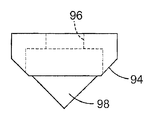
도 4A 내지 도 4D는 후술되는 바와 같이 액추에이터에 의한 제어를 위해 PZT 적층체의 기둥(88)에 장착될 예시적인 공구 팁 캐리어(90)의 도면이다. 도 4A는 공구 팁 캐리어(90)의 사시도이다. 도 4B는 공구 팁 캐리어(90)의 정면도이다. 도 4C는 공구 팁 캐리어(90)의 측면도이다. 도 4D는 공구 팁 캐리어(90)의 평면도이다.4A-4D are views of an exemplary
도 4A 내지 도 4D에 도시된 바와 같이, 공구 팁 캐리어(90)는, 평평한 후방 표면(92)과, 테이퍼진 전방 표면(94)과, 각진 또는 테이퍼진 측면들을 구비한 돌출 표면(98)을 포함한다. 개구(96)는 PZT 적층체의 기둥 상으로의 공구 팁 캐리어(90)의 장착을 제공한다. 테이퍼진 표면(98)은 공작물의 기계가공을 위한 공구 팁의 장착에 사용될 수 있다. 본 예시적인 실시예에서, 공구 팁 캐리어(90)는 PZT 적층체에 장착된 때 보다 큰 표면적의 접촉을 제공함으로써 그 장착 안정성을 향상시키기 위한 평평한 표면을 포함하며, 공구 팁 캐리어의 질량을 줄이기 위하여 테이퍼진 전방 표면을 포함한다. 공구 팁 캐리어(90)는 접착제, 경납땜, 연납땜, 볼트와 같은 체결구의 사용에 의해 또는 다른 방식으로 PZT 적층체의 기둥(88)에 장착될 것이다.4A-4D, the
예를 들어 특정 실시예의 요건에 근거하여 공구 팁 캐리어의 다른 구성이 가능하다. "공구 팁 캐리어"라는 용어는 공작물을 기계가공하기 위한 공구 팁을 보유하는 데 사용되는 임의의 유형의 구조물을 포함하고자 한다. 공구 팁 캐리 어(90)는 예를 들어 하기의 재료들 중 하나 이상의 재료로 구현될 수 있다: 소결된 탄화물, 질화규소, 탄화규소, 강철, 또는 티타늄. 공구 팁 캐리어(90)용 재료는 바람직하게는 강성이고 질량이 낮다.For example, other configurations of tool tip carriers are possible based on the requirements of a particular embodiment. The term "tool tip carrier" is intended to include any type of structure used to hold a tool tip for machining a workpiece.
도 5A 내지 도 5D는 접착제, 경납땜, 연납땜의 사용에 의해 또는 다른 방식으로 공구 팁 캐리어(90)의 표면(98)에 고정될 예시적인 공구 팁(100)의 도면이다. 도 5A는 공구 팁(100)의 사시도이다. 도 5B는 공구 팁(100)의 정면도이다. 도 5C는 공구 팁(100)의 저면도이다. 도 5D는 공구 팁(100)의 측면도이다. 도 5A 내지 도 5D에 도시된 바와 같이, 공구 팁(100)은 측면(104)과, 테이퍼지고 각진 전방 표면(106)과, 공구 팁 캐리어(90)의 표면(98)에 공구 팁을 고정하는 하부 표면(102)을 포함한다. 공구 팁(100)의 전방 부분(105)은 액추에이터의 제어 하에서 공작물을 기계가공하는 데 사용된다. 공구 팁(90)은 예를 들어 다이아몬드 슬래브(diamond slab)로 구현될 수 있다.5A-5D are illustrations of
X-Z 액추에이터X-Z actuator
도 6A 내지 도 6H는 예시적인 X-Z 액추에이터(110)의 도면이다. "X-Z 액추에이터"라는 용어는 공작물을 기계가공하는 데 사용하기 위해 공구 팁을 실질적으로 x-방향 및 z-방향 둘 모두로 이동시키는 임의의 유형의 액추에이터 또는 다른 장치를 말한다. 도 6A는 X-Z 액추에이터(110)의 평단면도이다. 도 6B는 X-Z 액추에이터(110)에서의 PZT 적층체의 배치를 도시한 측단면도이다. 도 6C는 X-Z 액추에이터(110)의 정면도이다. 도 6D는 X-Z 액추에이터(110)의 배면도이다. 도 6E는 X-Z 액추에이터(110)의 평면도이다. 도 6F 및 도 6G는 X-Z 액추에이터(110)의 측 면도이다. 도 6H는 X-Z 액추에이터(110)의 사시도이다. 도 6C 내지 도 6H에서 X-Z 액추에이터(110)에 대한 일부 상세부가 명료함을 위해 제거되어 있다.6A-6H are diagrams of exemplary
도 6A 내지 도 6H에 도시된 바와 같이, X-Z 액추에이터(110)는 x-방향 PZT 적층체(118)와 z-방향 PZT 적층체(116)를 보유할 수 있는 본체(112)를 포함한다. PZT 적층체(118, 116)는 화살표(138, 140)로 도시된 바와 같이 공구 팁을 x-방향 및 z-방향으로 각각 이동시키는 데 사용되는, 공구 팁(136)을 구비한 공구 팁 캐리어에 부착된다. PZT 적층체(118, 116)는 도 3에 도시된 예시적인 PZT 적층체(72)로 구현될 수 있다. 캐리어(136) 상의 공구 팁은 도 4A 내지 도 4D에 도시된 공구 팁 캐리어 및 도 5A 내지 도 5D에 도시된 공구 팁으로 구현될 수 있다. 본체(112)는 또한 컴퓨터(12)의 제어 하에서 공작물(54)을 기계가공하기 위해, 볼트에 의한 것과 같이 본체를 공구대(36)에 장착하는 데 사용되는 2개의 개구(114, 115)를 포함한다.As shown in FIGS. 6A-6H, the
PZT 적층체(118, 116)는 공구 팁(136)의 정밀 제어 이동에 필요한 안정성을 위해 본체(112)에 고정 장착된다. PZT 적층체(118)는 레일(120, 122)과 같은 레일에 의해 본체(112)에 고정되며, PZT 적층체(116)는 레일(124, 126)과 같은 레일에 의해 본체(112)에 고정된다. PZT 적층체(118, 116)는 바람직하게는 PZT 적층체를 레일을 따라 활주시킴으로써 본체(112)로부터 분리될 수 있으며, 볼트 또는 다른 체결구들에 의해 본체(112)의 제위치에 고정될 수 있다. PZT 적층체(118, 116)는 컴퓨터(12)로부터 신호를 수신하기 위한 전기 접속부(130, 134)를 각각 포함한다. PZT 적층체(118, 116)의 단부 캡은, PZT 적층체의 온도 제어를 유지하기 위해, 오 일과 같은 냉각 유체를 저장조(46)로부터 수용하여 이를 PZT 적층체 주위로 순환시키고 오일을 저장조(46)로 다시 전달하는 포트(128, 132)를 각각 포함한다. 본체(112)는 냉각 유체를 PZT 적층체(118, 116) 주위로 지향시키는 적절한 채널을 포함할 수 있으며, 냉각 유체는 온도 제어 유닛(52)의 펌프 또는 다른 장치에 의해 순환될 수 있다.The PZT stacks 118, 116 are fixedly mounted to the
도 6B는 PZT 적층체(118)의 단부 캡이 도시되지 않은 상태로, 본체(112)에서의 PZT 적층체(118)의 배치를 도시한 측단면도이다. 본체(112)는 PZT 적층체를 제위치에 고정되게 보유하기 위해 PZT 적층체를 위한 각각의 개구에서 복수의 레일을 포함할 수 있다. 예를 들어, PZT 적층체(118)는 본체(112)에 장착된 때 PZT 적층체를 제위치에 고정되게 보유하기 위하여 레일(120, 122, 142, 144)에 의해 둘러싸인다. PZT 적층체(118)에 부착된 단부 캡은 PZT 적층체를 레일(120, 122, 142, 144)들 중 하나 이상의 레일에 고정시키는 볼트 또는 다른 체결구를 수용할 수 있으며, 단부 캡은 또한 냉각 유체를 PZT 적층체 주위로 순환시키는 데 사용되는, 본체(112)에서의 PZT 적층체(118)의 밀봉을 제공할 수 있다. PZT 적층체(116)는 유사한 방식으로 장착될 수 있다. PZT 적층체(118, 116) 둘 모두는 그들의 예비 하중 인가를 위해 적층체와 공구 팁 캐리어(136) 사이에 위치된 하나 이상의 벨빌 와셔를 포함할 수 있다.FIG. 6B is a side cross-sectional view showing the arrangement of the
도 7A 내지 도 7D는 액추에이터(116, 118)를 공구 팁 캐리어(136)에 고정시키는 데 사용되는 패들(150)을 도시한다. 도 7A는 패들(150)의 사시도이다. 도 7B는 패들(150)의 평면도이다. 도 7C는 패들(150)의 정면도이다. 도 7D는 패 들(150)의 측면도이다. 도 7E는 패들(150)에 대한 2개의 PZT 적층체의 장착을 도시한 사시도이다. 도 7A 내지 도 7D에 도시된 바와 같이, 패들(150)은, z-방향 제어를 위해 PZT 적층체(116)에 고정되는 표면을 구비한 링 부분(ring portion, 156)과, x-방향 제어를 위해 PZT 적층체(118)에 고정되는 표면을 구비한 링 부분(152)을 포함한다. 본 실시예에서, 링 부분(152, 156)은 개구(154, 158)를 각각 구비한다. 개구(154)는 패들(150)을 예를 들어 체결구를 사용하여 PZT 적층체(118) 및 공구 팁 캐리어(136) 둘 모두에 고정시키는 데 사용될 수 있다. 패들(150)은 바람직하게는 티타늄으로 제조되며, 대안적으로 다른 재료로 제조될 수 있다. 예를 들어, 패들(150)은 대안적으로 알루미늄으로 구현될 수 있다. 패들(150)을 구현하기 위한 재료에 대한 인자로는 예를 들어 재료의 강도 대 중량 비를 들 수 있다. 액추에이터(116, 118)는 도 7E에 도시된 바와 같이 접착제, 경납땜, 연납땜의 사용에 의해 또는 다른 방식으로 패들(150)에 고정될 수 있다.7A-7D show paddles 150 used to secure
도 8은 X-Z 액추에이터를 구비한 절삭 공구 시스템을 사용하여 제조될 수 있는 미세 구조체를 개념적으로 도시한 도면이다. 도 8에 도시된 바와 같이, 용품(160)은 상부 표면(162) 및 하부 표면(164)을 포함한다. 상부 표면(162)은 선(166)으로 나타낸 바와 같은 미세 구조체를 포함하며, 이들 미세 구조체는 전술된 액추에이터를 사용하여 공작물을 기계가공한 다음에 그 공작물을 사용하여 코팅 기술을 이용해 필름 또는 용품을 제조함으로써 제조될 수 있다.8 conceptually illustrates a microstructure that can be manufactured using a cutting tool system with an X-Z actuator. As shown in FIG. 8,
본 발명이 예시적인 실시예와 관련하여 설명되었지만, 많은 변형예들이 당업자에게 용이하게 명백하게 될 것이며, 본 출원이 본 발명의 임의의 개작 또는 변형 을 포괄하고자 한다는 것을 이해할 것이다. 예를 들어, 본 발명의 범주로부터 벗어남이 없이 공구대, 액추에이터 및 공구 팁을 위한 여러 가지 유형의 재료들과 이들 구성요소들의 여러 가지 유형의 구성들이 사용될 수 있다. 본 발명은 청구의 범위와 그 균등물에 의해서만 한정되어야 한다.Although the present invention has been described in connection with exemplary embodiments, it will be understood that many variations will be readily apparent to those skilled in the art, and that the present application is intended to cover any adaptations or variations of the present invention. For example, different types of materials and different types of configurations of these components can be used for tool posts, actuators and tool tips without departing from the scope of the present invention. It is intended that this invention be limited only by the claims and the equivalents thereof.
Claims (21)
Applications Claiming Priority (3)
| Application Number | Priority Date | Filing Date | Title |
|---|---|---|---|
| US11/274,723 | 2005-11-15 | ||
| US11/274,723 US7293487B2 (en) | 2005-11-15 | 2005-11-15 | Cutting tool having variable and independent movement in an x-direction and a z-direction into and laterally along a work piece for making microstructures |
| PCT/US2006/042171 WO2007058758A1 (en) | 2005-11-15 | 2006-10-30 | Cutting tool having variable and independent movement in an x-direction and a z-direction into and laterally along a work piece for making microstructures |
Publications (2)
| Publication Number | Publication Date |
|---|---|
| KR20080072900A KR20080072900A (en) | 2008-08-07 |
| KR101312194B1 true KR101312194B1 (en) | 2013-09-27 |
Family
ID=38039398
Family Applications (1)
| Application Number | Title | Priority Date | Filing Date |
|---|---|---|---|
| KR1020087013393A KR101312194B1 (en) | 2005-11-15 | 2006-10-30 | Apparatus for machining having variable and independent movement in an x-direction and a z-direction into and laterally along a work piece for making microstructures and a method for machining a work piece with the same |
Country Status (7)
| Country | Link |
|---|---|
| US (2) | US7293487B2 (en) |
| EP (1) | EP1948392A4 (en) |
| JP (1) | JP2009515720A (en) |
| KR (1) | KR101312194B1 (en) |
| CN (1) | CN101304839B (en) |
| TW (1) | TWI363683B (en) |
| WO (1) | WO2007058758A1 (en) |
Families Citing this family (19)
| Publication number | Priority date | Publication date | Assignee | Title |
|---|---|---|---|---|
| US7677146B2 (en) * | 2006-05-10 | 2010-03-16 | 3M Innovative Properties Company | Cutting tool using one or more machined tool tips in a continuous or interrupted cut fast tool servo |
| DE102006026524A1 (en) * | 2006-06-06 | 2007-12-13 | Satisloh Ag | Machine for processing optical workpieces, in particular plastic spectacle lenses |
| US7628100B2 (en) * | 2007-01-05 | 2009-12-08 | 3M Innovative Properties Company | Cutting tool using one or more machined tool tips with diffractive features in a continuous or interrupted cut fast tool servo |
| KR20150076260A (en) * | 2007-09-21 | 2015-07-06 | 쓰리엠 이노베이티브 프로퍼티즈 컴파니 | Optical film |
| US7669508B2 (en) * | 2007-10-29 | 2010-03-02 | 3M Innovative Properties Company | Cutting tool using one or more machined tool tips with diffractive features |
| US20090147361A1 (en) * | 2007-12-07 | 2009-06-11 | 3M Innovative Properties Company | Microreplicated films having diffractive features on macro-scale features |
| KR101609400B1 (en) | 2008-04-02 | 2016-04-05 | 쓰리엠 이노베이티브 프로퍼티즈 컴파니 | Light directing film or light directing article |
| US20100128351A1 (en) * | 2008-11-21 | 2010-05-27 | 3M Innovative Properties Company | Curved sided cone structures for controlling gain and viewing angle in an optical film |
| US20100129617A1 (en) * | 2008-11-21 | 2010-05-27 | Corrigan Thomas R | Laser ablation tooling via sparse patterned masks |
| US20100186570A1 (en) * | 2009-01-29 | 2010-07-29 | 3M Innovative Properties Company | Method for making an optical film having a variable prismatic structured surface |
| US20100188751A1 (en) * | 2009-01-29 | 2010-07-29 | 3M Innovative Properties Company | Optical films with internally conformable layers and method of making the films |
| JP5344310B2 (en) * | 2009-02-26 | 2013-11-20 | 大日本印刷株式会社 | Optical sheet, surface light source device, transmissive display device, light emitting device and mold |
| US20110070398A1 (en) * | 2009-09-18 | 2011-03-24 | 3M Innovative Properties Company | Laser ablation tooling via distributed patterned masks |
| JP2014193514A (en) * | 2013-03-29 | 2014-10-09 | Nishijima Corp | Light guide plate processing apparatus |
| JP6470085B2 (en) * | 2015-03-26 | 2019-02-13 | シチズン時計株式会社 | Machine tool and control device for this machine tool |
| US20160307429A1 (en) | 2015-04-14 | 2016-10-20 | Hill-Rom Services, Inc. | Monitoring of patient supports |
| CN106976118B (en) * | 2017-05-11 | 2018-11-13 | 绍兴柯桥实在纺织有限公司 | A kind of catering trade fruit slice device |
| CN109530537B (en) * | 2018-11-20 | 2020-01-07 | 中北大学 | Magnetic micro-pit processing device |
| DE102019127628A1 (en) | 2019-10-14 | 2021-04-15 | Optotech Optikmaschinen Gmbh | Tool drive unit, turning device and turning method |
Citations (1)
| Publication number | Priority date | Publication date | Assignee | Title |
|---|---|---|---|---|
| KR20040096676A (en) * | 2003-05-10 | 2004-11-17 | 사단법인 고등기술연구원 연구조합 | A vibration cutting machine |
Family Cites Families (49)
| Publication number | Priority date | Publication date | Assignee | Title |
|---|---|---|---|---|
| JPS63306854A (en) | 1987-06-03 | 1988-12-14 | Hitachi Ltd | Tool control system for machine tool device |
| JPH01281848A (en) | 1988-05-09 | 1989-11-13 | Kobe Steel Ltd | Precision cutting device |
| JPH0735813B2 (en) * | 1989-08-30 | 1995-04-19 | 豊田工機株式会社 | Hydrostatic bearing |
| US5291812A (en) | 1992-05-22 | 1994-03-08 | General Motors Corporation | Turning apparatus with improved chip handling |
| US5467675A (en) | 1993-11-15 | 1995-11-21 | North Carolina State University | Apparatus and method for forming a workpiece surface into a non-rotationally symmetric shape |
| US5497675A (en) * | 1994-06-06 | 1996-03-12 | Chrysler Corporation | Energy absorber for a steering column |
| JPH09275689A (en) | 1996-04-01 | 1997-10-21 | Seiko Seiki Co Ltd | Ultra-precise positioning device |
| JP3690431B2 (en) | 1996-04-19 | 2005-08-31 | 株式会社前川製作所 | Scallop internal organs separation and suction device |
| GB2314452A (en) | 1996-06-17 | 1997-12-24 | Rank Taylor Hobson Ltd | Electromechanical actuator |
| US6040653A (en) | 1996-10-17 | 2000-03-21 | Kinetic Ceramics, Inc. | Piezoelectric positioner |
| JPH10118811A (en) | 1996-10-18 | 1998-05-12 | Matsushita Electric Ind Co Ltd | Machining device |
| US20020137890A1 (en) * | 1997-03-31 | 2002-09-26 | Genentech, Inc. | Secreted and transmembrane polypeptides and nucleic acids encoding the same |
| US6237452B1 (en) | 1997-12-29 | 2001-05-29 | Massachusetts Institute Of Technology | Precision high speed turning machine |
| CA2318790C (en) | 1998-02-18 | 2004-03-30 | Minnesota Mining And Manufacturing Company | Optical film |
| US6170367B1 (en) * | 1998-09-09 | 2001-01-09 | John R. Keller | Single-point flexure toric contact lens forming machine and method |
| SE515157C2 (en) | 1998-10-22 | 2001-06-18 | Ingvar Claesson | Method and apparatus for controlling turning operation |
| US6322236B1 (en) | 1999-02-09 | 2001-11-27 | 3M Innovative Properties Company | Optical film with defect-reducing surface and method for making same |
| WO2000050201A1 (en) | 1999-02-25 | 2000-08-31 | Micro Optics Design Corporation | Apparatus and method for generating ultimate surfaces on ophthalmic lenses |
| US6356391B1 (en) | 1999-10-08 | 2002-03-12 | 3M Innovative Properties Company | Optical film with variable angle prisms |
| US6845212B2 (en) | 1999-10-08 | 2005-01-18 | 3M Innovative Properties Company | Optical element having programmed optical structures |
| JP4398044B2 (en) | 2000-02-03 | 2010-01-13 | 東芝機械株式会社 | Numerical control device and control method for machine tool |
| US6581286B2 (en) | 2000-04-05 | 2003-06-24 | 3M Innovative Properties Company | Method of making tool to produce optical film |
| CA2313830A1 (en) | 2000-07-13 | 2002-01-13 | Micro Optics Design Corporation | Single point diamond turning lathe with vibration cancelling feature |
| US6753384B2 (en) | 2000-07-14 | 2004-06-22 | Metabolix, Inc. | Polyurethanes obtained from hydroxyalkanoates and isocyanates |
| JP4158956B2 (en) * | 2000-07-28 | 2008-10-01 | キッコーマン株式会社 | Method for producing gene encoding protein having ability to regenerate luciferin, recombinant DNA and protein having ability to regenerate luciferin |
| WO2002037168A2 (en) | 2000-11-01 | 2002-05-10 | Dac International, Inc. | Method and system for producing progressive addition spectacle lenses |
| JP3806603B2 (en) * | 2001-02-23 | 2006-08-09 | Towa株式会社 | Oval vibration device and control method of elliptic vibration device |
| JP4138270B2 (en) | 2001-05-15 | 2008-08-27 | 本田技研工業株式会社 | Engine fuel supply system |
| US20030035231A1 (en) | 2001-08-03 | 2003-02-20 | Epstein Kenneth A. | Optical film having microreplicated structures; and methods |
| US20030108710A1 (en) | 2001-12-07 | 2003-06-12 | General Electric Company | Articles bearing patterned microstructures and method of making |
| WO2003086688A1 (en) | 2002-04-15 | 2003-10-23 | Oren, Elimelech | Method and apparatus for vibrating cutting tool |
| US6862141B2 (en) | 2002-05-20 | 2005-03-01 | General Electric Company | Optical substrate and method of making |
| US7275468B2 (en) | 2002-05-29 | 2007-10-02 | Massachusetts Institute Of Technology | Rotary fast tool servo system and methods |
| US6945099B1 (en) * | 2002-07-02 | 2005-09-20 | Veeco Instruments Inc. | Torsional resonance mode probe-based instrument and method |
| US20040109683A1 (en) * | 2002-08-21 | 2004-06-10 | Meriton Networks Inc. | Non-disruptive lightpath routing changes in WDM networks |
| US20040045419A1 (en) | 2002-09-10 | 2004-03-11 | Bryan William J. | Multi-diamond cutting tool assembly for creating microreplication tools |
| JP2004098230A (en) | 2002-09-10 | 2004-04-02 | Canon Inc | Machining device, machining method, and displacement detection unit |
| US6811274B2 (en) | 2002-12-04 | 2004-11-02 | General Electric Company | Polarization sensitive optical substrate |
| US7125131B2 (en) | 2002-12-06 | 2006-10-24 | General Electric Company | Brightness enhancement film with improved view angle |
| US6909482B2 (en) | 2002-12-11 | 2005-06-21 | General Electric Company | Display substrate with reflective color filters |
| US6952627B2 (en) | 2002-12-18 | 2005-10-04 | General Electric Company | Method and apparatus for fabricating light management substrates |
| US6814113B1 (en) * | 2002-12-18 | 2004-11-09 | Ronald G. Daniels | Manufacturing method for producing three dimensional inlaid turned and re-sawn wood products |
| US6844950B2 (en) | 2003-01-07 | 2005-01-18 | General Electric Company | Microstructure-bearing articles of high refractive index |
| JP4013252B2 (en) * | 2003-03-27 | 2007-11-28 | 株式会社ジェイテクト | Hale processing method and processing apparatus |
| JP2005014169A (en) | 2003-06-27 | 2005-01-20 | Canon Inc | Feedback control apparatus and machining apparatus |
| EP1493530A1 (en) * | 2003-07-04 | 2005-01-05 | HESS, Peter | Tool head with piezoelectric actuators |
| KR100491304B1 (en) * | 2003-09-18 | 2005-05-24 | 미래산업 주식회사 | Sorting Handler for Burn-in Tester |
| WO2005043266A2 (en) | 2003-10-31 | 2005-05-12 | Massachusetts Institute Of Technology | Variable reluctance fast positioning system and methods |
| US8170367B2 (en) | 2008-01-28 | 2012-05-01 | Vistaprint Technologies Limited | Representing flat designs to be printed on curves of a 3-dimensional product |
-
2005
- 2005-11-15 US US11/274,723 patent/US7293487B2/en active Active
-
2006
- 2006-10-30 JP JP2008541193A patent/JP2009515720A/en not_active Withdrawn
- 2006-10-30 KR KR1020087013393A patent/KR101312194B1/en active IP Right Grant
- 2006-10-30 CN CN2006800421080A patent/CN101304839B/en not_active Expired - Fee Related
- 2006-10-30 WO PCT/US2006/042171 patent/WO2007058758A1/en active Application Filing
- 2006-10-30 EP EP06836614A patent/EP1948392A4/en not_active Withdrawn
- 2006-11-09 TW TW095141526A patent/TWI363683B/en not_active IP Right Cessation
-
2007
- 2007-10-02 US US11/865,770 patent/US7395741B2/en active Active
Patent Citations (1)
| Publication number | Priority date | Publication date | Assignee | Title |
|---|---|---|---|---|
| KR20040096676A (en) * | 2003-05-10 | 2004-11-17 | 사단법인 고등기술연구원 연구조합 | A vibration cutting machine |
Also Published As
| Publication number | Publication date |
|---|---|
| CN101304839A (en) | 2008-11-12 |
| KR20080072900A (en) | 2008-08-07 |
| US20080016993A1 (en) | 2008-01-24 |
| JP2009515720A (en) | 2009-04-16 |
| EP1948392A1 (en) | 2008-07-30 |
| CN101304839B (en) | 2012-11-28 |
| US20070107568A1 (en) | 2007-05-17 |
| TW200726611A (en) | 2007-07-16 |
| EP1948392A4 (en) | 2010-11-17 |
| US7293487B2 (en) | 2007-11-13 |
| WO2007058758A1 (en) | 2007-05-24 |
| US7395741B2 (en) | 2008-07-08 |
| TWI363683B (en) | 2012-05-11 |
Similar Documents
| Publication | Publication Date | Title |
|---|---|---|
| KR101312194B1 (en) | Apparatus for machining having variable and independent movement in an x-direction and a z-direction into and laterally along a work piece for making microstructures and a method for machining a work piece with the same | |
| KR101312207B1 (en) | Apparatus for machining a cylindrical work piece and method for using a fast z actuator to machine a work piece | |
| KR101312129B1 (en) | Apparatus for machining a cylindrical work piece and method for using a dual in-line actuator to machine a work piece | |
| KR101312233B1 (en) | Apparatus for machining a cylindrical work piece and method for using a virtual center y actuator to machine a work piece | |
| JP5296550B2 (en) | Cutting tools that use intermittent cutting high-speed tool servos | |
| KR101391499B1 (en) | Cutting tool assembly using one or more machined tool tips in a continuous or interrupted cut fast tool servo |
Legal Events
| Date | Code | Title | Description |
|---|---|---|---|
| A201 | Request for examination | ||
| E902 | Notification of reason for refusal | ||
| E701 | Decision to grant or registration of patent right | ||
| GRNT | Written decision to grant | ||
| FPAY | Annual fee payment |
Payment date: 20160818 Year of fee payment: 4 |
|
| FPAY | Annual fee payment |
Payment date: 20170818 Year of fee payment: 5 |
|
| FPAY | Annual fee payment |
Payment date: 20180816 Year of fee payment: 6 |