JP5296550B2 - Cutting tools that use intermittent cutting high-speed tool servos - Google Patents
Cutting tools that use intermittent cutting high-speed tool servos Download PDFInfo
- Publication number
- JP5296550B2 JP5296550B2 JP2008548629A JP2008548629A JP5296550B2 JP 5296550 B2 JP5296550 B2 JP 5296550B2 JP 2008548629 A JP2008548629 A JP 2008548629A JP 2008548629 A JP2008548629 A JP 2008548629A JP 5296550 B2 JP5296550 B2 JP 5296550B2
- Authority
- JP
- Japan
- Prior art keywords
- workpiece
- tool tip
- tool
- taper
- cutting
- Prior art date
- Legal status (The legal status is an assumption and is not a legal conclusion. Google has not performed a legal analysis and makes no representation as to the accuracy of the status listed.)
- Active
Links
- 238000005520 cutting process Methods 0.000 title description 49
- 230000033001 locomotion Effects 0.000 claims description 30
- 238000003754 machining Methods 0.000 claims description 14
- 239000000463 material Substances 0.000 description 27
- 238000000034 method Methods 0.000 description 19
- 239000010408 film Substances 0.000 description 16
- 238000010586 diagram Methods 0.000 description 9
- 239000010432 diamond Substances 0.000 description 9
- 229910003460 diamond Inorganic materials 0.000 description 9
- 239000012809 cooling fluid Substances 0.000 description 8
- 239000011295 pitch Substances 0.000 description 7
- 230000008569 process Effects 0.000 description 7
- 238000000605 extraction Methods 0.000 description 5
- 239000012530 fluid Substances 0.000 description 5
- 230000008901 benefit Effects 0.000 description 4
- 230000000694 effects Effects 0.000 description 4
- 230000006870 function Effects 0.000 description 4
- 239000003921 oil Substances 0.000 description 4
- 239000000853 adhesive Substances 0.000 description 3
- 230000001070 adhesive effect Effects 0.000 description 3
- 230000005684 electric field Effects 0.000 description 3
- 238000000227 grinding Methods 0.000 description 3
- 229910052751 metal Inorganic materials 0.000 description 3
- 239000002184 metal Substances 0.000 description 3
- 239000012788 optical film Substances 0.000 description 3
- 238000003860 storage Methods 0.000 description 3
- PXHVJJICTQNCMI-UHFFFAOYSA-N Nickel Chemical compound [Ni] PXHVJJICTQNCMI-UHFFFAOYSA-N 0.000 description 2
- 238000005219 brazing Methods 0.000 description 2
- 238000005266 casting Methods 0.000 description 2
- 238000000576 coating method Methods 0.000 description 2
- 238000009792 diffusion process Methods 0.000 description 2
- 238000005516 engineering process Methods 0.000 description 2
- 238000001125 extrusion Methods 0.000 description 2
- 238000007373 indentation Methods 0.000 description 2
- 230000004048 modification Effects 0.000 description 2
- 238000012986 modification Methods 0.000 description 2
- 230000003287 optical effect Effects 0.000 description 2
- 238000005057 refrigeration Methods 0.000 description 2
- 238000005476 soldering Methods 0.000 description 2
- 229910001369 Brass Inorganic materials 0.000 description 1
- RYGMFSIKBFXOCR-UHFFFAOYSA-N Copper Chemical compound [Cu] RYGMFSIKBFXOCR-UHFFFAOYSA-N 0.000 description 1
- 229910052581 Si3N4 Inorganic materials 0.000 description 1
- 229910000831 Steel Inorganic materials 0.000 description 1
- RTAQQCXQSZGOHL-UHFFFAOYSA-N Titanium Chemical compound [Ti] RTAQQCXQSZGOHL-UHFFFAOYSA-N 0.000 description 1
- NIXOWILDQLNWCW-UHFFFAOYSA-N acrylic acid group Chemical group C(C=C)(=O)O NIXOWILDQLNWCW-UHFFFAOYSA-N 0.000 description 1
- 239000002313 adhesive film Substances 0.000 description 1
- 229910052782 aluminium Inorganic materials 0.000 description 1
- XAGFODPZIPBFFR-UHFFFAOYSA-N aluminium Chemical compound [Al] XAGFODPZIPBFFR-UHFFFAOYSA-N 0.000 description 1
- 230000003667 anti-reflective effect Effects 0.000 description 1
- 229910002113 barium titanate Inorganic materials 0.000 description 1
- JRPBQTZRNDNNOP-UHFFFAOYSA-N barium titanate Chemical compound [Ba+2].[Ba+2].[O-][Ti]([O-])([O-])[O-] JRPBQTZRNDNNOP-UHFFFAOYSA-N 0.000 description 1
- 239000011324 bead Substances 0.000 description 1
- 238000005422 blasting Methods 0.000 description 1
- 239000010951 brass Substances 0.000 description 1
- 239000000919 ceramic Substances 0.000 description 1
- 229910010293 ceramic material Inorganic materials 0.000 description 1
- 230000008859 change Effects 0.000 description 1
- 238000003486 chemical etching Methods 0.000 description 1
- 239000011248 coating agent Substances 0.000 description 1
- 238000004891 communication Methods 0.000 description 1
- 239000002826 coolant Substances 0.000 description 1
- 229910052802 copper Inorganic materials 0.000 description 1
- 239000010949 copper Substances 0.000 description 1
- NKZSPGSOXYXWQA-UHFFFAOYSA-N dioxido(oxo)titanium;lead(2+) Chemical compound [Pb+2].[O-][Ti]([O-])=O NKZSPGSOXYXWQA-UHFFFAOYSA-N 0.000 description 1
- 238000005323 electroforming Methods 0.000 description 1
- 238000004049 embossing Methods 0.000 description 1
- 230000006872 improvement Effects 0.000 description 1
- 238000001746 injection moulding Methods 0.000 description 1
- HFGPZNIAWCZYJU-UHFFFAOYSA-N lead zirconate titanate Chemical compound [O-2].[O-2].[O-2].[O-2].[O-2].[Ti+4].[Zr+4].[Pb+2] HFGPZNIAWCZYJU-UHFFFAOYSA-N 0.000 description 1
- 239000004973 liquid crystal related substance Substances 0.000 description 1
- 239000000314 lubricant Substances 0.000 description 1
- 238000004519 manufacturing process Methods 0.000 description 1
- 238000005555 metalworking Methods 0.000 description 1
- 238000002156 mixing Methods 0.000 description 1
- 238000000465 moulding Methods 0.000 description 1
- 229910052759 nickel Inorganic materials 0.000 description 1
- 239000004033 plastic Substances 0.000 description 1
- 239000002861 polymer material Substances 0.000 description 1
- 238000012545 processing Methods 0.000 description 1
- 230000010076 replication Effects 0.000 description 1
- 230000004044 response Effects 0.000 description 1
- HBMJWWWQQXIZIP-UHFFFAOYSA-N silicon carbide Chemical compound [Si+]#[C-] HBMJWWWQQXIZIP-UHFFFAOYSA-N 0.000 description 1
- 229910010271 silicon carbide Inorganic materials 0.000 description 1
- HQVNEWCFYHHQES-UHFFFAOYSA-N silicon nitride Chemical compound N12[Si]34N5[Si]62N3[Si]51N64 HQVNEWCFYHHQES-UHFFFAOYSA-N 0.000 description 1
- 239000007787 solid Substances 0.000 description 1
- 229910001220 stainless steel Inorganic materials 0.000 description 1
- 239000010935 stainless steel Substances 0.000 description 1
- 239000010959 steel Substances 0.000 description 1
- 230000001629 suppression Effects 0.000 description 1
- 230000001360 synchronised effect Effects 0.000 description 1
- 239000010936 titanium Substances 0.000 description 1
- 229910052719 titanium Inorganic materials 0.000 description 1
- 238000012546 transfer Methods 0.000 description 1
- 239000012780 transparent material Substances 0.000 description 1
- 230000000007 visual effect Effects 0.000 description 1
Images


Classifications
-
- B—PERFORMING OPERATIONS; TRANSPORTING
- B23—MACHINE TOOLS; METAL-WORKING NOT OTHERWISE PROVIDED FOR
- B23B—TURNING; BORING
- B23B27/00—Tools for turning or boring machines; Tools of a similar kind in general; Accessories therefor
- B23B27/14—Cutting tools of which the bits or tips or cutting inserts are of special material
- B23B27/18—Cutting tools of which the bits or tips or cutting inserts are of special material with cutting bits or tips or cutting inserts rigidly mounted, e.g. by brazing
- B23B27/20—Cutting tools of which the bits or tips or cutting inserts are of special material with cutting bits or tips or cutting inserts rigidly mounted, e.g. by brazing with diamond bits or cutting inserts
-
- B—PERFORMING OPERATIONS; TRANSPORTING
- B23—MACHINE TOOLS; METAL-WORKING NOT OTHERWISE PROVIDED FOR
- B23Q—DETAILS, COMPONENTS, OR ACCESSORIES FOR MACHINE TOOLS, e.g. ARRANGEMENTS FOR COPYING OR CONTROLLING; MACHINE TOOLS IN GENERAL CHARACTERISED BY THE CONSTRUCTION OF PARTICULAR DETAILS OR COMPONENTS; COMBINATIONS OR ASSOCIATIONS OF METAL-WORKING MACHINES, NOT DIRECTED TO A PARTICULAR RESULT
- B23Q15/00—Automatic control or regulation of feed movement, cutting velocity or position of tool or work
- B23Q15/007—Automatic control or regulation of feed movement, cutting velocity or position of tool or work while the tool acts upon the workpiece
- B23Q15/14—Control or regulation of the orientation of the tool with respect to the work
-
- B—PERFORMING OPERATIONS; TRANSPORTING
- B23—MACHINE TOOLS; METAL-WORKING NOT OTHERWISE PROVIDED FOR
- B23B—TURNING; BORING
- B23B29/00—Holders for non-rotary cutting tools; Boring bars or boring heads; Accessories for tool holders
- B23B29/04—Tool holders for a single cutting tool
- B23B29/12—Special arrangements on tool holders
- B23B29/125—Vibratory toolholders
-
- B—PERFORMING OPERATIONS; TRANSPORTING
- B23—MACHINE TOOLS; METAL-WORKING NOT OTHERWISE PROVIDED FOR
- B23Q—DETAILS, COMPONENTS, OR ACCESSORIES FOR MACHINE TOOLS, e.g. ARRANGEMENTS FOR COPYING OR CONTROLLING; MACHINE TOOLS IN GENERAL CHARACTERISED BY THE CONSTRUCTION OF PARTICULAR DETAILS OR COMPONENTS; COMBINATIONS OR ASSOCIATIONS OF METAL-WORKING MACHINES, NOT DIRECTED TO A PARTICULAR RESULT
- B23Q15/00—Automatic control or regulation of feed movement, cutting velocity or position of tool or work
- B23Q15/007—Automatic control or regulation of feed movement, cutting velocity or position of tool or work while the tool acts upon the workpiece
- B23Q15/08—Control or regulation of cutting velocity
-
- B—PERFORMING OPERATIONS; TRANSPORTING
- B81—MICROSTRUCTURAL TECHNOLOGY
- B81C—PROCESSES OR APPARATUS SPECIALLY ADAPTED FOR THE MANUFACTURE OR TREATMENT OF MICROSTRUCTURAL DEVICES OR SYSTEMS
- B81C99/00—Subject matter not provided for in other groups of this subclass
-
- B—PERFORMING OPERATIONS; TRANSPORTING
- B23—MACHINE TOOLS; METAL-WORKING NOT OTHERWISE PROVIDED FOR
- B23B—TURNING; BORING
- B23B2260/00—Details of constructional elements
- B23B2260/108—Piezoelectric elements
-
- G—PHYSICS
- G05—CONTROLLING; REGULATING
- G05B—CONTROL OR REGULATING SYSTEMS IN GENERAL; FUNCTIONAL ELEMENTS OF SUCH SYSTEMS; MONITORING OR TESTING ARRANGEMENTS FOR SUCH SYSTEMS OR ELEMENTS
- G05B2219/00—Program-control systems
- G05B2219/30—Nc systems
- G05B2219/41—Servomotor, servo controller till figures
- G05B2219/41344—Piezo, electrostrictive linear drive
-
- Y—GENERAL TAGGING OF NEW TECHNOLOGICAL DEVELOPMENTS; GENERAL TAGGING OF CROSS-SECTIONAL TECHNOLOGIES SPANNING OVER SEVERAL SECTIONS OF THE IPC; TECHNICAL SUBJECTS COVERED BY FORMER USPC CROSS-REFERENCE ART COLLECTIONS [XRACs] AND DIGESTS
- Y10—TECHNICAL SUBJECTS COVERED BY FORMER USPC
- Y10T—TECHNICAL SUBJECTS COVERED BY FORMER US CLASSIFICATION
- Y10T82/00—Turning
- Y10T82/10—Process of turning
-
- Y—GENERAL TAGGING OF NEW TECHNOLOGICAL DEVELOPMENTS; GENERAL TAGGING OF CROSS-SECTIONAL TECHNOLOGIES SPANNING OVER SEVERAL SECTIONS OF THE IPC; TECHNICAL SUBJECTS COVERED BY FORMER USPC CROSS-REFERENCE ART COLLECTIONS [XRACs] AND DIGESTS
- Y10—TECHNICAL SUBJECTS COVERED BY FORMER USPC
- Y10T—TECHNICAL SUBJECTS COVERED BY FORMER US CLASSIFICATION
- Y10T82/00—Turning
- Y10T82/16—Severing or cut-off
- Y10T82/16426—Infeed means
-
- Y—GENERAL TAGGING OF NEW TECHNOLOGICAL DEVELOPMENTS; GENERAL TAGGING OF CROSS-SECTIONAL TECHNOLOGIES SPANNING OVER SEVERAL SECTIONS OF THE IPC; TECHNICAL SUBJECTS COVERED BY FORMER USPC CROSS-REFERENCE ART COLLECTIONS [XRACs] AND DIGESTS
- Y10—TECHNICAL SUBJECTS COVERED BY FORMER USPC
- Y10T—TECHNICAL SUBJECTS COVERED BY FORMER US CLASSIFICATION
- Y10T82/00—Turning
- Y10T82/25—Lathe
- Y10T82/2512—Lathe having facing tool fed transverse to work
-
- Y—GENERAL TAGGING OF NEW TECHNOLOGICAL DEVELOPMENTS; GENERAL TAGGING OF CROSS-SECTIONAL TECHNOLOGIES SPANNING OVER SEVERAL SECTIONS OF THE IPC; TECHNICAL SUBJECTS COVERED BY FORMER USPC CROSS-REFERENCE ART COLLECTIONS [XRACs] AND DIGESTS
- Y10—TECHNICAL SUBJECTS COVERED BY FORMER USPC
- Y10T—TECHNICAL SUBJECTS COVERED BY FORMER US CLASSIFICATION
- Y10T82/00—Turning
- Y10T82/25—Lathe
- Y10T82/2583—Tool and work rest
Landscapes
- Engineering & Computer Science (AREA)
- Mechanical Engineering (AREA)
- Microelectronics & Electronic Packaging (AREA)
- Turning (AREA)
- Moulds For Moulding Plastics Or The Like (AREA)
- Micromachines (AREA)
- Control Of Cutting Processes (AREA)
- Milling Processes (AREA)
- Grinding And Polishing Of Tertiary Curved Surfaces And Surfaces With Complex Shapes (AREA)
- Perforating, Stamping-Out Or Severing By Means Other Than Cutting (AREA)
Description
機械加工技術は、微細複製工具のような幅広い工作物を作製するのに使用することができる。微細複製工具は、微細複製構造を作製するための押出成形プロセス、射出成形プロセス、エンボス加工プロセス、キャスティングプロセスなどで広く用いられている。微細複製構造には、光学フィルム、研磨フィルム、接着フィルム、自己噛合輪郭を備える機械的留め具、又は、比較的小さい寸法、例えば約1000ミクロン未満の寸法の微細複製構造を備える任意の成形又は押出し部品などが含まれる。 Machining techniques can be used to make a wide range of workpieces such as microreplication tools. The fine duplication tool is widely used in an extrusion process, an injection molding process, an embossing process, a casting process, and the like for producing a fine duplication structure. The microreplicated structure can be an optical film, an abrasive film, an adhesive film, a mechanical fastener with a self-engaging profile, or any molding or extrusion with a microreplicated structure of relatively small dimensions, eg, less than about 1000 microns. Parts etc. are included.
ミクロ構造は、他の様々な方法によっても作製することができる。例えば、マスター工具から製造物工具を形成するキャスト及び硬化プロセスによって、マスター工具の構造を高分子材料のベルト又はウェブのような他の媒体に転写することが可能であり、さらにこの製造工具を使用して微細複製構造が作成される。マスター工具を複写するために、電鋳法のような他の方法を使用することができる。光配向フィルムを作成する他の代替的な方法は、透明材料を直接切削又は機械加工して適切な構造を形成するというものである。他の技術には、化学的エッチング、ビードブラスト、又は他の確率的表面修正技術が挙げられる。 The microstructure can also be made by various other methods. For example, it is possible to transfer the structure of the master tool to another medium, such as a belt or web of polymeric material, by using a casting and curing process that forms a product tool from the master tool. Thus, a fine replication structure is created. Other methods such as electroforming can be used to copy the master tool. Another alternative method of making the photo-alignment film is to directly cut or machine the transparent material to form the appropriate structure. Other techniques include chemical etching, bead blasting, or other stochastic surface modification techniques.
第1切削工具アセンブリは、ツールポスト及びこのツールポストに取り付けられ、コントローラと電気通信的に連結するように構成されている作動装置を備える。作動装置に取り付けられる工具チップは、切削すべき工作物に対して移動するように備え付けられる。作動装置は、工具チップを工作物内外へx方向に移動させ、この工具チップは切削中工作物と不連続に接触する。 The first cutting tool assembly includes a tool post and an actuator attached to the tool post and configured to be in electrical communication with the controller. A tool tip attached to the actuator is provided for movement relative to the workpiece to be cut. The actuating device moves the tool tip in and out of the workpiece in the x direction, and the tool tip contacts the workpiece discontinuously during cutting.
第2切削工具アセンブリは、ツールポスト及びこのツールポストに取り付けられ、コントローラと電気通信的に連結するように設計されている作動装置を備える。作動装置に取り付けられる工具チップは、切削すべき工作物に対して移動するように備え付けられる。作動装置は、工具チップを工作物内外へx方向に移動させる。工具チップは、切削中に工作物と不連続に接触し、アセンブリは切削中に工具チップが工作物に入るテーパイン角度と工作物から工具チップから出るテーパアウト角度を変更することができる。 The second cutting tool assembly includes a tool post and an actuator attached to the tool post and designed to communicatively connect with the controller. A tool tip attached to the actuator is provided for movement relative to the workpiece to be cut. The actuator moves the tool tip in and out of the workpiece in the x direction. The tool tip contacts the workpiece discontinuously during cutting, and the assembly can change the taper-in angle at which the tool tip enters the workpiece and the taper-out angle from the workpiece out of the tool tip during cutting.
切削工具システム
一般的なダイヤモンド旋盤技術は、PCT公開出願WO00/48037号に記載されている。種々の方法に使用される装置、及び光学フィルム又は他のフィルムを作成するための装置は、高速サーボ工具を備えることができる。WO00/48037号に開示されているように、高速工具サーボ(FTS)は、ソリッドステート圧電(PZT)素子であって、PZTスタックと称され、PZTスタックに取り付けられる切削工具の位置を迅速に調節する。FTSは、さらに以下に記載されるように、座標系内の方向に切削工具を非常に正確に且つ高速で移動することを可能とする。
Cutting Tool System General diamond lathe technology is described in PCT published application WO 00/48037. Devices used in various methods, and devices for making optical films or other films, can comprise high speed servo tools. As disclosed in WO00 / 48037, high speed tool servo (FTS) is a solid state piezoelectric (PZT) element, referred to as PZT stack, which quickly adjusts the position of the cutting tool attached to the PZT stack To do. FTS makes it possible to move the cutting tool very accurately and at high speed in directions within the coordinate system, as will be further described below.
図1は、工作物内にミクロ構造を作成する切削工具システム10の図である。ミクロ構造には、任意の種類、形状、及び寸法の、物品の表面上、物品の表面へのインデント、又は物品の表面からの隆起が含まれる。例えば、本明細書に記載の作動装置及びシステムを使用して作製されるミクロ構造は、1000ミクロンピッチ、100ミクロンピッチ、1ミクロンピッチ、又はさらには200ナノメートル付近のサブ光波長ピッチを有することができる。あるいは、他の実施形態において、ミクロ構造におけるピッチは、切削方法に関わらず1000ミクロンを超えることができる。これらの寸法は例示することだけを目的し、本明細書に記載の作動装置及びシステムを使用して作成されるミクロ構造は、システムを使用して加工可能な範囲内で任意の寸法を有することができる。
FIG. 1 is a diagram of a
システム10は、コンピュータ12によって制御される。コンピュータ12は、例えば構成要素として、1つ以上のアプリケーション16を記憶するメモリ14、情報の不揮発性記憶装置を提供する二次記憶装置18、情報又はコマンドを受信する入力デバイス20;メモリ16又は二次記憶装置内に記憶されるか、他のソースから受信されるアプリケーションを実行する処理装置22、情報の視覚的表示を出力する表示装置24、及び聴覚情報におけるスピーカー又は情報のハードコピーにおけるプリンタのように他の形態で情報を出力する出力デバイス26、を有する。
工作物54の切削は工作チップ44によって実行される。作動装置38は、コンピュータ12によって制御される電動モータのような駆動装置及びエンコーダ56によって、工作物54が回転する際の工具チップ44の運動を制御する。本実施例においては、工作物54はロール状であるが、平面状で実行することも可能である。任意の機械加工可能な材料を使用することができ、例えば工作物は、アルミニウム、ニッケル、銅、黄銅、又はプラスチック(例えばアクリル)で構成することが可能である。使用される特定の材料は、例えば、機械加工された工作物を使用して作成されつ様々なフィルムのような特定の望ましい用途によって決めることができる。作動装置38、及び以下に記載される作動装置は、例えばステンレス鋼、又は他の材料で構成することができる。
Cutting of the
作動装置38は、ツールポスト36に取り外し可能に連結され、さらにツールポスト36はトラック32上に配置される。ツールポスト36及び作動装置38は、トラック32上を矢印40及び42が示すx方向及びz方向の双方に移動するように構成される。コンピュータ12は、1つ以上の増幅器30を介してツールポスト36及び作動装置38と電気的に接続される。制御装置として機能する場合、コンピュータ12は工作物54を機械加工のために、作動装置38を介して、トラック32に沿ったツールポスト36の移動及び工具チップ44の移動を制御する。作動装置が複数のPZTスタックを有する場合、スタックに取り付けられる工具チップの移動を独立して制御するのに使用される各PZTスタックを独立して制御するために、個別に増幅器を使用することができる。コンピュータ12は、以下でさらに説明するように、工作物54中に様々なミクロ構造を機械加工するために、作動装置38に波形を提供する関数発生器28を使用することができる。
工作物54の機械加工は、様々な構成要素の運動を調整することで達成される。特に、コンピュータ12の制御下において、システムは、ツールポスト36の移動を介して、c方向での工作物の移動並びにx方向、y方向、及びz方向(これらの座標は以下で説明される)のうちの1つ以上での工具チップ44の移動に伴った作動装置38の移動を調整及び制御することができる。システムは、典型的に、ツールポスト36をz方向に定速で移動させるが、変速も使用してよい。ツールポスト36及び工具チップ44の移動は、典型的にc方向での工作物54の移動(線53で表されるような回転運動)と同期化されている。これらの全移動は、例えば、ソフトウェア、ファームウェア、又はコンピュータ1内中の組み合わせで実行される数値制御技術又は数値制御装置(NC)を使用して制御できる。
Machining of the
工作物の切削は、連続的及び不連続的な切削運動を含むことができる。ロール状の工作物において、ヘリックス型切削(ねじ切りと称されることもある)又はロール周り若しくはロールに対して独立した軌道を切削に含めることができる。平面状の工作物において、らせん型切削又は工作物上若しくは工作物に対して独立した軌道を切削に含めることができる。X切削も使用することが可能であり、この場合は切削形式はほぼ直線であり、ダイヤモンド工具チップは工作物の内外を移動するが、ツールポストの総体的運動は直線状である。切削には、これらの種類の運動の組み合わせを含めることができる。 The cutting of the workpiece can include continuous and discontinuous cutting motions. In a rolled workpiece, the cutting can include helix-type cutting (sometimes referred to as threading) or a track around or independent of the roll. In planar workpieces, the cutting can include helical cutting or trajectories that are independent of or on the workpiece. X cutting can also be used, in which case the type of cutting is approximately linear and the diamond tool tip moves in and out of the workpiece, but the overall movement of the tool post is linear. Cutting can include a combination of these types of motion.
機械加工後の工作物54は、様々な用途での使用に応じたミクロ構造を有するフィルムを作成するのに使用できる。これらのフィルムの例としては、光学フィルム、摩擦抑制フィルム、及びミクロ締結具又は他の機械的ミクロ構造化構成要素が挙げられる。フィルムは、典型的には、粘稠な状態のポリマー材料を工作物に塗布するコーティング工程を使用して作成され、少なくとも部分的に硬化させた後に取り除かれる。硬化したポリマー材料から構成されるフィルムは、実質的に工作物と逆の構造を有する。例えば、工作物に圧痕があれば、生じるフィルムには突出が生じる。機械加工後の工作物54は、工具が有する構造に対応する別個の要素又はミクロ構造を有する他の物品の作成にも使用することができる。
The
冷却流体46は、線48及び50を介してツールポスト36及び作動装置38の温度を制御するのに使用される。温度制御装置52は、ツールポスト36及び作動装置38を循環する冷却流体の温度を実質一定に維持することができる。温度制御装置52は、流体の温度制御を提供するため、任意のデバイスで実装できる。冷却流体は、例えば低粘度油のような油製品で構成することができる。温度制御装置52及び冷却流体46のリザーバは、ツールポスト36及び作動装置38中に流体を循環させるポンプを備え、典型的には、実質定温で維持するために流体からの熱を取り除く冷凍システムも備える。流体を循環させ、温度制御を提供する冷凍及びポンプシステムは当該技術分野において既知である。特定の実施形態において、工作物の機械加工される材料の表面温度を実質一定に維持するために、冷却流体を工作物54に適用することも可能である。
The
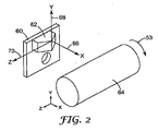
図2は、システム10のような切削工具における座標系を示す図である。座標系は、工作物64に対する工具チップ62の移動として示されている。工具チップ62は工具チップ44と一致してよく、作動装置に取り付けられるキャリア60に典型的に取り付けられる。この代表的な実施形態において、座標系には、x方向66、y方向68、及びz方向70が含まれる。x方向66は、工作物64に対して実質的に垂直な方向への移動を指す。y方向68は、工作物64の回転面に対して実質平行な方向のような、工作物64を横切る方向への移動を指す。z方向70は、工作物64の回転軸に対して実質平行な方向のような、工作物64の横に沿った方向への運動を指す。工作物の回転は、図1にも示されるように、c方向と称される。工作物が平面状に構成される際、ロール状とは対照的にy方向及びz方向は、x方向に対して実質垂直な方向で工作物を互いに直交する方向での運動を指す。平面状の工作物には、例えば、回転ディスク又は任意の平面材料の他の構成が挙げられる。
FIG. 2 is a diagram illustrating a coordinate system in a cutting tool such as the
システム10は、高精度且つ高速の機械加工に使用することができる。この種類の機械加工では、構成要素と工作物材料の協調速度のような様々なパラメーターを考慮すべきである。典型的には、例えば、工作物材料の熱安定性及び特性とともに、機械加工すべき金属の所定体積の比エネルギーを考慮すべきである。機械加工に関する切削パラメーターは、以下の参考文献に記載されている。「機械加工データハンドブック(Machining Data Handbook)」(米国議会図書館カタログカード番号66−60051(Library of Congress Catalog Card No. 66-60051)第2版(1972年)、エドワードトレント(Edward Trent)及びポールライト(Paul Wright)による「金属切削(Metal Cutting)」(第4版バターワースハイネマン(Butterworth-Heinemann)ISBN0−7506−7069−X(2000年)、ジャンジン−ホワン(Zhang Jin-Hua)による「精密切削の理論及び技術(Theory and Technique of Precision Cutting)」(ペルガモンプレス(Pergamon Press)ISBN0−08−035891−8(1991年)、及びクルーガー(Krueger)他による「金属加工油における新技術及び10倍の切削性能向上を達成する切削ホール(New Technology in Metalworking Fluids and Grinding Wheels Achieves Tenfold Improvement in Grinding Performance)」(金属切削及び研削におけるクーラント/潤滑剤協議会(Coolant/Lubricants for Metal Cutting and Grinding Conference)2000年6月7日米国イリノイ州)。
The
PZTスタック、工具チップキャリア、及び工具チップ
図3は、切削工具に使用する代表的なPZTスタック72の図である。PZTスタックは連結される工具チップを移動させるのに使用され、当該技術分野において既知であるPZT効果に従って作動する。PZT効果によると、特定の種類の材料に適用される電界によって、その材料は1つの軸に沿って膨張し、他の軸に沿って収縮する。PZTスタックは、典型的に、ケーシング84に内包され、ベースプレート86上に備え付けられる複数の材料74、76、及び78を備える。この代表的な実施形態において、材料は、PZT効果の対象となるセラミック材料で構成される。例示のみを目的として、3つのディスク74、76、及び78が示されているが、例えば特定の実施形態における必要性に基づいて、任意数のディスク又は他の材料、若しくは任意の種類の形状を使用することができる。ポスト88はディスクに付着し、ケーシング84から突出している。ディスクは、例えば、チタン酸バリウム、ジルコン酸鉛、又はチタン酸鉛材料を混合、圧縮、主材料とし、焼結したような任意のPZT材料で構成することができる。かかるPZT材料の1つは、米国カリフォルニア州ヘイワード(Hayward)(CA94545)産業通り(Industrial Blvd.)26240のキネティックセラミックス(Kinetic Ceramics)社から市販されている。ディスクは、例えば、磁歪材料で構成することもできる。
PZT Stack, Tool Tip Carrier, and Tool Tip FIG. 3 is a diagram of an
線80及び82で表されるように、ディスク74、76、及び78への電気的接続によって、ポスト88が移動するための電場が生成される。PZT効果及び適用される電場の種類によって、数ミクロン以内の移動のようにポスト88の正確且つ僅かな移動を達成できる。また、ポスト88を有するPZTスタック72の末端部は、PZTスタックの予め搭載できる1つ以上のベルビルワッシャに備え付けることが可能である。ベルビルワッシャは、ポスト88及びそれに取り付けられる工具チップを移動させるために若干の可撓性を有する。
As represented by
図4A〜4Dは、代表的な工具チップキャリア90の図であり、これは以下で説明するように、作動装置による制御のためにPZTスタックのポスト88に備え付けられ得る。図4Aは、工具チップキャリア90の斜視図である。図4Bは、工具チップキャリア90の正面図である。図4Cは、工具チップキャリア90の側面図である。図4Dは、工具チップキャリア90の平面図である。
4A-4D are views of an exemplary
図4A〜4Dに示すように、工具チップキャリア90は、平面裏面92、テーパー前面94、及び角度が付けられるか又はテーパー化された側面を有する隆起表面98を備える。開口部96は、キャリア90のPZTスタックのポスト上への工具ツールの実装に対応する。テーパー表面98は、工作物の機械加工において工具チップの実装に使用され得る。この代表的な実施形態において、工具チップキャリア90は、PZTスタックに備え付けられる際により多くの表面積が接触することで備え付けの安定性を向上する平面を備え、質量を削減するためにテーパー状前面を備える。工具チップキャリア90は、接着剤、ろう付け、はんだ付け、ボルトのような締結具、又は他の方法によってPZTスタックのポスト88に備え付けられ得る。
As shown in FIGS. 4A-4D,
例えば、特定の実施形態における必要性に応じて、工具チップの他の構成が可能である。用語「工具チップキャリア」は、工作物を機械加工する工具チップを保持するのに使用する任意の種類の構造を含んでいる。工具チップキャリア90は、例えば、以下の材料、焼結炭化物、窒化ケイ素、炭化ケイ素、鋼、チタン、ダイヤモンド、又は合成ダイヤモンド材料、の1つ以上で構成することができる。工具チップキャリア90における材料は、剛性があり低質量であることが好ましい。
For example, other configurations of tool tips are possible depending on the needs in a particular embodiment. The term “tool tip carrier” includes any type of structure used to hold a tool tip for machining a workpiece. The
図5A〜5Dは代表的な工具チップ100の図であり、これは、接着剤、ろう付け、はんだ付け、又は他の方法などを使用して工具チップキャリア90の表面98に固定され得る。図5Aは、工具チップ100の斜視図である。図5Bは、工具チップ100の正面図である。図5Cは、工具チップ100の底面図である。図5Dは、工具チップ100の側面図である。図5Aから5Dに示すように、工具チップ100は側面104、テーパー状且つ角度が付けられた前面106、及び工具チップキャリア90の表面98に固定するための底面102を備える。工具チップ100の前側部分105は、作動装置の制御下で工作物を機械加工するのに使用される。工具チップ90は、例えば、ダイヤモンドスラブで構成することができる。
5A-5D are views of an exemplary tool tip 100, which may be secured to the
断続切削FTS作動装置
断続切削FTS作動装置は、切削中に工具チップが工作物と不連続に接触し、近接しないミクロ構造を作製するため、小型マイクロ構造の作成に使用することができる。これらの形状は、導光フィルム、ミクロ流体構造、セグメント化接着剤、研磨材物品、光学ディフューザー、高コントラスト光学スクリーン、光リダイレクトフィルム、抗反射構造、光混合、及び装飾フィルムを作成するのに使用することができる。
Intermittent Cutting FTS Actuator The interrupted cutting FTS actuating device can be used to create a small microstructure because the tool tip discontinuously contacts the workpiece during cutting and creates a microstructure that is not in close proximity. These shapes are used to create light guide films, microfluidic structures, segmented adhesives, abrasive articles, optical diffusers, high contrast optical screens, light redirect films, anti-reflective structures, light mixing, and decorative films can do.
作動装置は他の利点を提供できる。例えば、上記の形状は、肉眼で見えないほど小さく作成することが可能である。この種類の形状により、例えば、液晶ディスプレイにおいて光抽出機能を非表示とする拡散シートの必要性が低くなる。光ガイド上におけるBEFフィルムの交差によって、これらの小さな形状の結合によって、拡散層が不要になる。他の利点は、抽出形状を線状又は円状にできることである。線状の場合、抽出を例えば従来の冷陰極蛍光ランプ(CCFL)光源に使用することが可能である。円状の場合、形状は通常はLEDが配置されるであろう場所に配置される点を中心とする円弧上に作成することができる。全ての形状を連続的な溝と同様に単線に沿って配置する必要がない場合、さらにプログラミング及び構造レイアウトに関連する利点がある。光抽出機能の面密度は、形状に沿って間隔を配列し、形状に直交するように間隔を空け、深さによって確定的に調整することが可能である。さらには、光抽出角は、切削面の角度及び半角度を選択することで優先することができる。 Actuators can provide other benefits. For example, the above shape can be made so small that it cannot be seen with the naked eye. This type of shape, for example, reduces the need for a diffusion sheet that hides the light extraction function in a liquid crystal display. Due to the intersection of the BEF films on the light guide, these small shaped bonds eliminate the need for a diffusion layer. Another advantage is that the extraction shape can be linear or circular. If linear, the extraction can be used, for example, with a conventional cold cathode fluorescent lamp (CCFL) light source. In the case of a circle, the shape can be created on an arc centered at the point where it would normally be placed. There are further advantages associated with programming and structural layout when not all shapes need to be placed along a single line, as with continuous grooves. The surface density of the light extraction function can be deterministically adjusted according to the depth by arranging the intervals along the shape and providing an interval so as to be orthogonal to the shape. Furthermore, the light extraction angle can be prioritized by selecting the angle and half angle of the cutting surface.
形状の深さは、0〜35ミクロン、例えば、より典型的には0〜15ミクロンの範囲であり得る。ロール状の工作物において、任意の個別の形状の長さは、回転する工作物の毎分回転数によって管理される。形状の長さは、例えば、1〜200ミクロンに管理することができる。ヘリックス型切削において、溝(ピッチ)に対して直交する空隙も1〜1000ミクロンにプログラムすることができる。以下に示すように、形状を作成する工具チップは材料にテーパイン及びテーパアウトし、それによって構造、RPMによって制御される形状、FTSの応答時間、スピンドルエンコーダの分解能、及びダイヤモンド工具チップの逃げ角度(例えば、最大で45℃)が決まる。逃げ角度は、工具チップのすくい角度を含んでもよい。形状は、例えば、左右対称、左右非対称、略半球状、プリズム型、及び略楕円体のような三次元形状の任意の型であってよい。 The depth of the shape can range from 0 to 35 microns, for example, more typically from 0 to 15 microns. In a rolled workpiece, the length of any individual shape is governed by the number of revolutions per minute of the rotating workpiece. The length of the shape can be controlled to 1 to 200 microns, for example. In helix-type cutting, the gap perpendicular to the groove (pitch) can also be programmed to 1-1000 microns. As shown below, the tool tip that creates the shape tapers in and out of the material so that the structure, the shape controlled by the RPM, the FTS response time, the resolution of the spindle encoder, and the clearance angle of the diamond tool tip ( For example, the maximum is 45 ° C.). The relief angle may include a rake angle of the tool tip. The shape may be any type of a three-dimensional shape such as, for example, left / right symmetry, left / right asymmetric, substantially hemispherical, prismatic, and substantially ellipsoidal.
図6A〜6Hは、断続切削微細構造システム及びプロセスを実行するのに使用する代表的な作動装置110の図である。用語「作動装置」は、工作物の機械加工に用いる、工具チップを実質的にx方向に移動させる任意の種類の作動装置又は他のデバイスを指す。図6Aは、作動装置110の上部断面図である。図6Bは、作動装置110におけるPZTスタックの配置を示す正面断面図である。図6Cは、作動装置110の正面図である。図6Dは、作動装置110の背面図である。図6Eは、作動装置110の平面図である。図6F及び6Gは、作動装置110の側面図である。図6Hは、作動装置110の斜視図である。図6C〜6Hにおける作動装置110の詳細の一部は、明確にするために取り除かれている。
6A-6H are diagrams of an
図6A〜6Hに示すように、作動装置110は、x方向にPZTスタック118を保持することができる本体112を備える。PZTスタック118は、矢印138に示すように、x方向に工具チップを移動するのに使用する工具チップ136を有する工具チップキャリアに取り付けられる。PZTスタック118は、図3に示すように、複数のPZTスタック72で実装することができる。キャリア136上の工具チップは、図4A〜4Dに示される工具チップキャリア及び図5A〜5Dに示される工具チップで構成することができる。本体112は、コンピュータ12の制御下で工作物54を機械加工するために、ボルトなどによりツールポスト36に取り外し可能に備え付けるのに使用する2つの開口部114及び115も備える。
As shown in FIGS. 6A-6H, the
PZTスタック118は、工具チップ136を正確に制御して移動させるのに必要とされる安定性のため、本体112に強固に備え付けられる。本実施例において、工具チップ136上のダイヤモンドは、垂直面に対してダイヤモンドが45度のオフセット型であるが、他の種類のダイヤモンドが使用され得る。例えば、工具チップはV型(対称又は非対称)、円頭型、平型、又は曲面型の工具であってよい。不連続(非隣接)な形状は、ダイヤモンド旋盤で切削して線状又は円状にすることができる。さらに形状は連続していないため、単一の線又は円に沿って配置される必要がない。特徴的形状は、擬似ランダム的に散在してよい。
The
PZTスタック118は、レール120及び122のようなレールによって本体112に固定される。PZTスタック118は、好ましくはレールに沿ってスライドさせることで本体から取り外され、ボルト又は他の締結具によって本体112内の所定の場所に固定することが可能である。PZTスタック118は、コンピュータ12から信号を受信する電気的接続130を備える。PZTスタック118のエンドキャップは、ポート132を介して、温度制御を維持するために、リザーバ46からの油のような冷却流体を受け入れ、PZTスタック周囲に循環し、油をリザーバ46に戻すためのポート128を備える。本体112は、冷却流体をPZTスタック118の周囲に向ける適切なチャネルを備え、冷却流体はポンプ又は他のデバイスによって温度制御装置52内を循環することが可能である。
図6Bは、PZTスタック118のエンドキャップ(図示せず)を備える本体112中のPZTスタック118の配置を示す正面断面図である。本体112は、所定の位置での固定を保持するために、PZTスタックにおける各開口部に複数のレールを備えることができる。例えば、PZTスタック118は、本体112中に取り付けられる際、所定の場所での固定を保持するために、レール120、122、142及び144に囲まれている。PZTスタック118に取り付けられるエンドキャップは、レール120、122、142及び144のうちの1つ以上にPZTスタックを固定するボルト又は他の締結具に適合することが可能であり、エンドキャップにまた、冷却流体に周囲を循環させるのに使用する本体112内にPZTスタック118を封入することも可能である。PZTスタック118は、スタックと工具チップキャリア136を予め搭載するためにその間に配置する1つ以上のベルビルワッシャを備える。
FIG. 6B is a front cross-sectional view showing the arrangement of the
図7A〜7Cは、上述の代表的な作動装置及びシステムを使用する工作物の断続切削機械加工を示す。特に、図7A〜7Cは、工具チップの可変テーパイン角度及び可変テーパアウト角度を使用を示し、これらの角度は、例えば上記に示すパラメーターを使用して制御することが可能である。図7A〜7Cの各々は、変動するテーパイン角度及びテーパアウト角度で切削される前後の工作物の例を示している。テーパイン角度はλIN、テーパアウト角度はλOUTとしてある。用語「テーパイン角度」「テーパアウト角度」は、それぞれ、機械加工中に工具チップが工作物に挿入され、工作物から離れる角度を意味する。テーパイン角度及びテーパアウト角度は、工作物内を移動する工具チップの角度に必ずしも対応せず、むしろ工具チップが工作物に接触し、離れる角度を指す。図7A〜7Cにおいて、工具チップ及び工作物は、例えば上述のシステム及び構成要素で構成することができる。 FIGS. 7A-7C illustrate intermittent cutting machining of a workpiece using the representative actuator and system described above. In particular, FIGS. 7A-7C illustrate the use of variable taper-in and variable taper-out angles of the tool tip, which can be controlled using, for example, the parameters shown above. Each of FIGS. 7A-7C shows an example of a workpiece before and after being cut with varying taper-in and taper-out angles. The taper-in angle is λ IN and the taper-out angle is λ OUT . The terms “taper-in angle” and “taper-out angle” mean the angle at which a tool tip is inserted into and away from the workpiece during machining, respectively. The taper-in and taper-out angles do not necessarily correspond to the angle of the tool tip moving through the workpiece, but rather refer to the angle at which the tool tip contacts and leaves the workpiece. 7A-7C, the tool tip and workpiece can be comprised of, for example, the systems and components described above.
図7Aは、工作物153の内外のテーパイン及びテーパアウト角度が実質的に等しい断続切削150を示す図である。図7Aに示すように、工作物153に入る工具チップ151のテーパイン角度152は、テーパアウト度角154(λIN≒λOUT)と実質的に等しい。工作物153内に工具チップ151が留まる時間によって、生じるミクロ構造の長さL(156)が決まる。実質等しいテーパイン及びテーパアウト角度を使用し、工具チップによって工作物から材料を取り除くことで実質左右対称なミクロ構造が作製される。このプロセスは、距離D(162)によって分離されるミクロ構造160のような付加的なミクロ構造を作成するために繰り返すことが可能である。
FIG. 7A is a diagram illustrating an interrupted
図7Bは、工作物167の内外においてテーパイン角度がテーパアウト角度より小さい断続切削を示す図である。図7Bに示すように、工作物167に入る工具チップ165のテーパイン角度166は、テーパアウト角度168(λIN<λOUT)未満である。工作物167内に工具チップ165が留まる時間によって、生じるミクロ構造の長さ170が決まる。テーパアウト角度より小さいテーパイン角度を使用し、工具チップによって工作物から材料を取り除くことで、例えばミクロ構造172のような左右非対称のミクロ構造が作製される。このプロセスは、距離176によって分離されるミクロ構造174のような付加的なミクロ構造を作成するために繰り返すことが可能である。
FIG. 7B is a diagram illustrating intermittent cutting in which the taper-in angle is smaller than the taper-out angle inside and outside the
図7Cは、工作物181の内外においてテーパイン角度がテーパアウト角度より大きい断続切削を示す図である。図7Cに示すように、工作物181に入る工具チップ179のテーパイン角度180は、テーパアウト角度182より大きい。工作物181内に工具チップ17が留まる時間によって、生じるミクロ構造の長さ184が決まる。テーパアウト角度より大きいテーパイン角度を使用し、工具チップによって工作物から材料を取り除くことで、例えばミクロ構造186のように左右非対称のミクロ構造が作製される。このプロセスは、距離190によって分離されるミクロ構造188のような付加的なミクロ構造を作成するために繰り返すことが可能である。
FIG. 7C is a diagram showing intermittent cutting in which the taper-in angle is larger than the taper-out angle inside and outside the
図7A〜7Cにおいて、テーパイン角度及びテーパアウト角度に対する破線(152、154、166、168、180、182)は、工具チップが工作物を出入りする角度の例を概念的に示すことを意図している。工作物を切削する間、工具チップは、例えば、線形経路、湾曲経路、線形及び湾曲運動の組み合わせを含む経路、又は特別な機能によって確定される経路等の任意決まった種類の経路を移動することができる。 7A-7C, the dashed lines for the taper-in and taper-out angles (152, 154, 166, 168, 180, 182) are intended to conceptually illustrate examples of angles at which the tool tip enters and exits the workpiece. Yes. While cutting a workpiece, the tool tip moves along any type of path, such as, for example, a linear path, a curved path, a path including a combination of linear and curved motion, or a path defined by a special function. Can do.
図8は、機械加工された工作物を作成するための断続切削FTS作動装置を有し、工作物が構造化フィルムを作成するために使用する切削工具システムを使用して作成できるミクロ構造を概念的に示す図である。図8に示すように、物品200は、上面202及び下面204を備える。上面202は、構造206、208、及び210のような断続切削隆起ミクロ構造を備え、これらのミクロ構造は工作物を機械加工するために上述の作動装置及びシステムを使用して作成することが可能であり、さらにコーティング技術を使用してこの工作物からフィルム又は物品を作成するのに使用される。本実施形態において、各ミクロ構造は長さLを有し、連続切削ミクロ構造は距離Dによって分離され、隣接したミクロ構造はピッチPによって分離される。これらのパラメーターの実行における実施形態は上述したとおりである。
FIG. 8 conceptualizes a microstructure that can be created using a cutting tool system that has an interrupted cutting FTS actuator to create a machined workpiece and that the workpiece uses to create a structured film. FIG. As shown in FIG. 8, the
例示的な実施形態に関して記載されており、多くの変形が当業者にとって明らかであり、本出願はあらゆる調整又は変更を含み得ることを理解されたい。例えば、ツールポスト、作動装置、及び工具チップにおいて様々な種類の材料及びそれらの構成要素の配置が発明の範囲を逸脱することなく使用され得る。本発明は、特許請求の範囲及びその等価物にのみ限定される。 While described with respect to exemplary embodiments, it should be understood that many variations will be apparent to those skilled in the art and that this application may include any adjustments or modifications. For example, various types of materials and their component arrangements can be used in tool posts, actuators, and tool tips without departing from the scope of the invention. The invention is limited only by the claims and the equivalents thereof.
添付図面は本明細書の一部に組み込まれ、構成するものであって、該明細書の記載と共に本明細書の利点と原則を説明する。 The accompanying drawings are incorporated in and constitute a part of this specification, and together with the description, explain the advantages and principles of this specification.
Claims (1)
前記工作物を回転させる駆動装置と、
トラック上に配置され、前記工作物の被加工面に実質平行に移動するように構成されたツールポストと、
前記ツールポストに取り付けられた作動装置と、
前記駆動装置及び前記作動装置に接続された制御装置と、を備え、
前記作動装置は、
開口部を有する本体と、
前記本体の開口部内に固定されかつ予め搭載された圧電スタックと、
前記圧電スタックに接続された工具チップキャリアと、
前記工具チップキャリアに取り付けられた工具チップと、を有し、
前記圧電スタックは、前記工作物の被加工面に実質垂直なx方向に前記工具チップを移動させ、
前記制御装置は、前記駆動装置による前記工作物の前記工具チップに対する移動を制御するとともに、前記圧電スタックによる前記工具チップの移動を制御し、
前記圧電スタックは加工中に、前記工具チップを前記工作物の被加工面の内外に移動させ、前記工作物の被加工面に不連続な形状を形成し、
前記制御装置は、前記工作物の表面に対する前記工具チップの機械加工中の移動を、
(1)前記工作物の表面内に入るときの前記工具チップのテーパイン角度が、前記工作物の表面から前記工具チップが離れるときのテーパアウト角度と実質等しくなる移動と、
(2)前記工作物の表面内に入るときの前記工具チップのテーパイン角度が、前記工作物の表面から前記工具チップが離れるときのテーパアウト角度よりも小さくなる移動と、
(3)前記工作物の表面内に入るときの前記工具チップのテーパイン角度が、前記工作物の表面から前記工具チップが離れるときのテーパアウト角度よりも大きくなる移動と、の間で変更可能に制御し、
前記不連続な形状は、35マイクロメートル以下の深さと、200マイクロメートル以下の長さとを有するミクロ構造である、システム。 A system for machining a cylindrical workpiece,
A drive for rotating the workpiece;
A tool post disposed on a track and configured to move substantially parallel to a work surface of the workpiece;
An actuator attached to the tool post;
A control device connected to the drive device and the actuating device,
The actuating device is:
A body having an opening;
A piezoelectric stack fixed and pre-mounted in the opening of the body;
A tool tip carrier connected to the piezoelectric stack;
A tool tip attached to the tool tip carrier,
The piezoelectric stack moves the tool tip in the x direction substantially perpendicular to the work surface of the workpiece,
The control device controls movement of the workpiece with respect to the tool tip by the driving device, and controls movement of the tool tip by the piezoelectric stack,
During the machining, the piezoelectric stack moves the tool tip in and out of the work surface of the workpiece to form a discontinuous shape on the work surface of the workpiece ,
The control device moves the tool tip relative to the surface of the workpiece during machining,
(1) a movement in which a taper-in angle of the tool tip when entering the surface of the workpiece is substantially equal to a taper-out angle when the tool tip leaves the surface of the workpiece;
(2) a movement in which a taper-in angle of the tool tip when entering the surface of the workpiece is smaller than a taper-out angle when the tool tip moves away from the surface of the workpiece;
(3) The taper-in angle of the tool tip when entering the surface of the workpiece can be changed between a movement that becomes larger than the taper-out angle when the tool tip moves away from the surface of the workpiece. Control
The discontinuous shape is a microstructure having a depth of 35 micrometers or less and a length of 200 micrometers or less .
Applications Claiming Priority (3)
| Application Number | Priority Date | Filing Date | Title |
|---|---|---|---|
| US11/318,707 US7328638B2 (en) | 2005-12-27 | 2005-12-27 | Cutting tool using interrupted cut fast tool servo |
| US11/318,707 | 2005-12-27 | ||
| PCT/US2006/048806 WO2007075898A1 (en) | 2005-12-27 | 2006-12-21 | Cutting tool using interrupted cut fast tool servo |
Publications (3)
| Publication Number | Publication Date |
|---|---|
| JP2009521337A JP2009521337A (en) | 2009-06-04 |
| JP2009521337A5 JP2009521337A5 (en) | 2010-01-28 |
| JP5296550B2 true JP5296550B2 (en) | 2013-09-25 |
Family
ID=38192077
Family Applications (1)
| Application Number | Title | Priority Date | Filing Date |
|---|---|---|---|
| JP2008548629A Active JP5296550B2 (en) | 2005-12-27 | 2006-12-21 | Cutting tools that use intermittent cutting high-speed tool servos |
Country Status (7)
| Country | Link |
|---|---|
| US (1) | US7328638B2 (en) |
| JP (1) | JP5296550B2 (en) |
| KR (1) | KR101397795B1 (en) |
| CN (1) | CN101346210B (en) |
| DE (1) | DE112006003585T5 (en) |
| TW (1) | TWI418422B (en) |
| WO (1) | WO2007075898A1 (en) |
Families Citing this family (63)
| Publication number | Priority date | Publication date | Assignee | Title |
|---|---|---|---|---|
| US7677146B2 (en) * | 2006-05-10 | 2010-03-16 | 3M Innovative Properties Company | Cutting tool using one or more machined tool tips in a continuous or interrupted cut fast tool servo |
| DE102006026524A1 (en) * | 2006-06-06 | 2007-12-13 | Satisloh Ag | Machine for processing optical workpieces, in particular plastic spectacle lenses |
| US7628100B2 (en) * | 2007-01-05 | 2009-12-08 | 3M Innovative Properties Company | Cutting tool using one or more machined tool tips with diffractive features in a continuous or interrupted cut fast tool servo |
| US9180524B2 (en) | 2007-08-06 | 2015-11-10 | 3M Innovative Properties Company | Fly-cutting head, system and method, and tooling and sheeting produced therewith |
| US20090041553A1 (en) * | 2007-08-06 | 2009-02-12 | 3M Innovative Properties Company | Fly-cutting system and method, and related tooling and articles |
| WO2009042286A1 (en) * | 2007-09-21 | 2009-04-02 | 3M Innovative Properties Company | Optical film |
| US7669508B2 (en) * | 2007-10-29 | 2010-03-02 | 3M Innovative Properties Company | Cutting tool using one or more machined tool tips with diffractive features |
| US20090147361A1 (en) * | 2007-12-07 | 2009-06-11 | 3M Innovative Properties Company | Microreplicated films having diffractive features on macro-scale features |
| JP5148259B2 (en) * | 2007-12-14 | 2013-02-20 | 株式会社 東北テクノアーチ | Processing equipment |
| JP4553967B2 (en) * | 2008-03-19 | 2010-09-29 | パナソニック株式会社 | Cutting apparatus, processing method, and mold processed by the processing method |
| WO2009124107A1 (en) * | 2008-04-02 | 2009-10-08 | 3M Innovative Properties Company | Light directing film and method for making the same |
| WO2009146055A2 (en) * | 2008-04-02 | 2009-12-03 | 3M Innovative Properties Company | Methods and systems for fabricating optical films having superimposed features |
| US20100186570A1 (en) * | 2009-01-29 | 2010-07-29 | 3M Innovative Properties Company | Method for making an optical film having a variable prismatic structured surface |
| KR101683938B1 (en) | 2009-06-02 | 2016-12-07 | 쓰리엠 이노베이티브 프로퍼티즈 컴파니 | Light redirecting film and display using this film |
| WO2011019785A1 (en) * | 2009-08-12 | 2011-02-17 | 3M Innovative Properties Company | Lightguide |
| EP2470930A1 (en) | 2009-08-25 | 2012-07-04 | 3M Innovative Properties Company | Light redirecting film and display system incorporating same |
| JP6100684B2 (en) | 2010-05-07 | 2017-03-22 | スリーエム イノベイティブ プロパティズ カンパニー | Anti-reflective film with microstructured surface |
| US8659829B2 (en) | 2010-08-05 | 2014-02-25 | 3M Innovative Properties Company | Multilayer film comprising matte surface layer and articles |
| CN102350509B (en) * | 2011-08-20 | 2013-03-06 | 吉林大学 | Method for turning complicated optical curved surface by utilizing equal chip loads |
| CN104335109B (en) | 2011-11-23 | 2018-01-12 | 3M创新有限公司 | optical stack with asymmetric diffuser |
| JP6293057B2 (en) | 2011-12-21 | 2018-03-14 | スリーエム イノベイティブ プロパティズ カンパニー | Optical film laminate |
| WO2013142084A1 (en) | 2012-03-20 | 2013-09-26 | 3M Innovative Properties Company | Structured optical film |
| KR102267204B1 (en) | 2013-10-02 | 2021-06-22 | 쓰리엠 이노베이티브 프로퍼티즈 컴파니 | Microstructured diffuser comprising first microstructured layer and coating, optical stacks, and method |
| KR102296607B1 (en) | 2013-10-02 | 2021-09-02 | 쓰리엠 이노베이티브 프로퍼티즈 컴파니 | Article comprising polyacrylate pressure sensitive primer and adhesive comprising polyacrylate component |
| KR102280969B1 (en) | 2013-10-02 | 2021-07-26 | 쓰리엠 이노베이티브 프로퍼티즈 컴파니 | Articles and methods comprising polyacrylate primer with nitrogen-containing polymer |
| JP6176449B2 (en) * | 2013-10-24 | 2017-08-09 | 富士ゼロックス株式会社 | Lens array manufacturing method |
| US9599766B2 (en) | 2014-04-16 | 2017-03-21 | 3M Innovative Properties Company | Laminated display unit |
| US9778407B2 (en) | 2014-04-16 | 2017-10-03 | 3M Innovative Properties Company | Light guide |
| WO2015191339A1 (en) | 2014-06-13 | 2015-12-17 | 3M Innovative Properties Company | Optical stacks for sparkle reduction |
| KR102200036B1 (en) | 2014-06-13 | 2021-01-07 | 쓰리엠 이노베이티브 프로퍼티즈 컴파니 | Optical stacks for sparkle reduction |
| US9919339B2 (en) | 2014-06-18 | 2018-03-20 | 3M Innovation Properties Company | Optical film |
| JP7009992B2 (en) | 2014-10-20 | 2022-01-26 | スリーエム イノベイティブ プロパティズ カンパニー | Micro-optical layer and method including adiabatic glazing unit and micro-structured diffuser |
| US10656312B2 (en) | 2015-06-30 | 2020-05-19 | 3M Innovative Properties Company | Insulated glazing units and microoptical layer including microstructured anisotropic diffuser and methods |
| US10761320B2 (en) | 2015-12-09 | 2020-09-01 | 3M Innovative Properties Company | Optical stack including a grating |
| US10663745B2 (en) | 2016-06-09 | 2020-05-26 | 3M Innovative Properties Company | Optical system |
| JP7138051B2 (en) | 2016-06-09 | 2022-09-15 | スリーエム イノベイティブ プロパティズ カンパニー | Display system and light guide |
| KR20180004707A (en) | 2016-06-09 | 2018-01-12 | 쓰리엠 이노베이티브 프로퍼티즈 컴파니 | Optical system |
| EP3487914A1 (en) | 2016-07-22 | 2019-05-29 | 3M Innovative Properties Company | Structured film and articles thereof |
| CN106597993A (en) * | 2016-10-28 | 2017-04-26 | 北京海普瑞森科技发展有限公司 | Software architecture of fast tool servo control system |
| WO2018152467A1 (en) | 2017-02-20 | 2018-08-23 | 3M Innovative Properties Company | Self-wetting adhesive composition |
| JP7115810B2 (en) | 2017-02-20 | 2022-08-09 | スリーエム イノベイティブ プロパティズ カンパニー | Self-wetting adhesive composition |
| JP7237006B2 (en) | 2017-03-02 | 2023-03-10 | スリーエム イノベイティブ プロパティズ カンパニー | Dynamic reflective color film with low optical caliper sensitivity |
| CN110662988A (en) | 2017-06-02 | 2020-01-07 | 3M创新有限公司 | Optical film and optical system |
| WO2018229609A1 (en) | 2017-06-12 | 2018-12-20 | 3M Innovative Properties Company | Stretchable conductors |
| US20220001644A1 (en) | 2017-06-26 | 2022-01-06 | 3M Innovative Properties Company | Structured film and articles thereof |
| EP3645275A1 (en) | 2017-06-26 | 2020-05-06 | 3M Innovative Properties Company | Structured film and articles thereof |
| EP3646396A1 (en) | 2017-06-26 | 2020-05-06 | 3M Innovative Properties Company | Structured film and articles thereof |
| US10665366B2 (en) | 2017-12-21 | 2020-05-26 | 3M Innovative Properties Company | Electrical ribbon cable |
| US11906701B2 (en) | 2017-12-29 | 2024-02-20 | 3M Innovative Properties Company | Anti-reflective surface structures |
| US11402637B2 (en) | 2018-04-20 | 2022-08-02 | 3M Innovative Properties Company | Headset and head-mounted display |
| CN113195604B (en) | 2018-12-18 | 2024-04-26 | 3M创新有限公司 | Polymeric film with structured surface |
| JP7135221B2 (en) | 2019-05-31 | 2022-09-12 | スリーエム イノベイティブ プロパティズ カンパニー | Composite cooling films and articles containing same |
| US11906252B2 (en) | 2019-05-31 | 2024-02-20 | 3M Innovative Properties Company | Composite cooling film and article including the same |
| US11766822B2 (en) | 2019-08-20 | 2023-09-26 | 3M Innovative Properties Company | Microstructured surface with increased microorganism removal when cleaned, articles and methods |
| WO2021124122A1 (en) | 2019-12-19 | 2021-06-24 | 3M Innovative Properties Company | Composite cooling film comprising a reflective microporous layer and a uv-absorbing layer |
| EP4078049A4 (en) | 2019-12-19 | 2024-01-24 | 3M Innovative Properties Company | Composite cooling film comprising an organic polymeric layer, a uv-absorbing layer, and a reflective metal layer |
| US20230008147A1 (en) | 2019-12-31 | 2023-01-12 | 3M Innovative Properties Company | Multi-surface passive cooling articles |
| WO2021144714A1 (en) | 2020-01-16 | 2021-07-22 | 3M Innovative Properties Company | Composite cooling film comprising a reflective nonporous organic polymeric layer and a uv-protective layer |
| US20230213243A1 (en) | 2020-05-06 | 2023-07-06 | 3M Innovative Properties Company | Solar Energy Absorbing and Radiative Cooling Articles and Methods |
| EP4284176A1 (en) | 2021-01-28 | 2023-12-06 | 3M Innovative Properties Company | Antimicrobial compositions and articles and related methods |
| JP2025500774A (en) | 2021-12-07 | 2025-01-15 | スリーエム イノベイティブ プロパティズ カンパニー | MICROSTRUCTURED SURFACES AND ARTICLES WITH LOW SCRATCH VISIBILITY AND METHODS - Patent application |
| WO2024047419A1 (en) | 2022-08-31 | 2024-03-07 | Solventum Intellectual Properties Company | Articles including a microstructured curved surface, tooling articles, and methods |
| WO2024141815A1 (en) | 2022-12-28 | 2024-07-04 | 3M Innovative Properties Company | Multilayered articles including a uv barrier layer |
Family Cites Families (45)
| Publication number | Priority date | Publication date | Assignee | Title |
|---|---|---|---|---|
| CA94545A (en) | 1904-08-27 | 1905-08-01 | Isaac N. Price | Fireproof window |
| JPH0698554B2 (en) | 1986-09-22 | 1994-12-07 | 豊田工機株式会社 | Numerical control processing equipment |
| JPH0735813B2 (en) * | 1989-08-30 | 1995-04-19 | 豊田工機株式会社 | Hydrostatic bearing |
| US5291812A (en) * | 1992-05-22 | 1994-03-08 | General Motors Corporation | Turning apparatus with improved chip handling |
| US5467675A (en) * | 1993-11-15 | 1995-11-21 | North Carolina State University | Apparatus and method for forming a workpiece surface into a non-rotationally symmetric shape |
| JP3259750B2 (en) * | 1994-11-30 | 2002-02-25 | 株式会社デンソー | Piezo actuator |
| JPH09269489A (en) * | 1996-02-02 | 1997-10-14 | Hitachi Ltd | Manufacture of liquid crystal display device and light transmission plate for rear illuminating part |
| JPH09275689A (en) | 1996-04-01 | 1997-10-21 | Seiko Seiki Co Ltd | Ultra-precise positioning device |
| GB2314452A (en) | 1996-06-17 | 1997-12-24 | Rank Taylor Hobson Ltd | Electromechanical actuator |
| US6040653A (en) * | 1996-10-17 | 2000-03-21 | Kinetic Ceramics, Inc. | Piezoelectric positioner |
| JPH10328902A (en) * | 1997-05-26 | 1998-12-15 | Sony Corp | Spiral groove forming machine |
| US6237452B1 (en) * | 1997-12-29 | 2001-05-29 | Massachusetts Institute Of Technology | Precision high speed turning machine |
| EP1975649A1 (en) * | 1998-02-18 | 2008-10-01 | Minnesota Mining And Manufacturing Company | Optical film |
| US6170367B1 (en) * | 1998-09-09 | 2001-01-09 | John R. Keller | Single-point flexure toric contact lens forming machine and method |
| SE515157C2 (en) * | 1998-10-22 | 2001-06-18 | Ingvar Claesson | Method and apparatus for controlling turning operation |
| US6322236B1 (en) * | 1999-02-09 | 2001-11-27 | 3M Innovative Properties Company | Optical film with defect-reducing surface and method for making same |
| EP1163081A1 (en) | 1999-02-25 | 2001-12-19 | Micro Optics Design Corporation | Apparatus and method for generating ultimate surfaces on ophthalmic lenses |
| US6356391B1 (en) * | 1999-10-08 | 2002-03-12 | 3M Innovative Properties Company | Optical film with variable angle prisms |
| US6845212B2 (en) * | 1999-10-08 | 2005-01-18 | 3M Innovative Properties Company | Optical element having programmed optical structures |
| JP4398044B2 (en) * | 2000-02-03 | 2010-01-13 | 東芝機械株式会社 | Numerical control device and control method for machine tool |
| US6581286B2 (en) * | 2000-04-05 | 2003-06-24 | 3M Innovative Properties Company | Method of making tool to produce optical film |
| CA2313830A1 (en) | 2000-07-13 | 2002-01-13 | Micro Optics Design Corporation | Single point diamond turning lathe with vibration cancelling feature |
| US6753384B2 (en) * | 2000-07-14 | 2004-06-22 | Metabolix, Inc. | Polyurethanes obtained from hydroxyalkanoates and isocyanates |
| JP4158956B2 (en) * | 2000-07-28 | 2008-10-01 | キッコーマン株式会社 | Method for producing gene encoding protein having ability to regenerate luciferin, recombinant DNA and protein having ability to regenerate luciferin |
| AU2002211873A1 (en) | 2000-11-01 | 2002-05-15 | Dac International, Inc. | Method and system for producing progressive addition spectacle lenses |
| JP2002301601A (en) | 2001-04-05 | 2002-10-15 | Canon Inc | Work device and work method |
| JP4119109B2 (en) * | 2001-10-17 | 2008-07-16 | 株式会社フジキン | Piezoelectric element driven metal diaphragm type control valve |
| US20030108710A1 (en) * | 2001-12-07 | 2003-06-12 | General Electric Company | Articles bearing patterned microstructures and method of making |
| AU2003215876A1 (en) | 2002-04-15 | 2003-10-27 | Eduard Gots | Method and apparatus for vibrating cutting tool |
| US6862141B2 (en) * | 2002-05-20 | 2005-03-01 | General Electric Company | Optical substrate and method of making |
| US7275468B2 (en) * | 2002-05-29 | 2007-10-02 | Massachusetts Institute Of Technology | Rotary fast tool servo system and methods |
| US6945099B1 (en) * | 2002-07-02 | 2005-09-20 | Veeco Instruments Inc. | Torsional resonance mode probe-based instrument and method |
| JP2004098230A (en) | 2002-09-10 | 2004-04-02 | Canon Inc | Machining device, machining method, and displacement detection unit |
| US20040045419A1 (en) * | 2002-09-10 | 2004-03-11 | Bryan William J. | Multi-diamond cutting tool assembly for creating microreplication tools |
| US6811274B2 (en) * | 2002-12-04 | 2004-11-02 | General Electric Company | Polarization sensitive optical substrate |
| US7125131B2 (en) * | 2002-12-06 | 2006-10-24 | General Electric Company | Brightness enhancement film with improved view angle |
| US6909482B2 (en) * | 2002-12-11 | 2005-06-21 | General Electric Company | Display substrate with reflective color filters |
| US6952627B2 (en) * | 2002-12-18 | 2005-10-04 | General Electric Company | Method and apparatus for fabricating light management substrates |
| US6814113B1 (en) * | 2002-12-18 | 2004-11-09 | Ronald G. Daniels | Manufacturing method for producing three dimensional inlaid turned and re-sawn wood products |
| US6844950B2 (en) * | 2003-01-07 | 2005-01-18 | General Electric Company | Microstructure-bearing articles of high refractive index |
| JP4013252B2 (en) * | 2003-03-27 | 2007-11-28 | 株式会社ジェイテクト | Hale processing method and processing apparatus |
| KR100514991B1 (en) | 2003-05-10 | 2005-09-15 | 고등기술연구원연구조합 | A vibration cutting machine |
| WO2005043266A2 (en) | 2003-10-31 | 2005-05-12 | Massachusetts Institute Of Technology | Variable reluctance fast positioning system and methods |
| TWM255084U (en) * | 2004-01-30 | 2005-01-11 | Jen-Rung Li | Cutting tools for micro actuating Scott-Russell linear mechanism |
| DE102004020990B4 (en) * | 2004-04-23 | 2008-05-21 | Schott Ag | Apparatus and method for producing microstructures |
-
2005
- 2005-12-27 US US11/318,707 patent/US7328638B2/en active Active
-
2006
- 2006-12-21 WO PCT/US2006/048806 patent/WO2007075898A1/en active Application Filing
- 2006-12-21 KR KR1020087015502A patent/KR101397795B1/en active IP Right Grant
- 2006-12-21 JP JP2008548629A patent/JP5296550B2/en active Active
- 2006-12-21 CN CN2006800492584A patent/CN101346210B/en active Active
- 2006-12-21 DE DE112006003585T patent/DE112006003585T5/en active Pending
- 2006-12-26 TW TW095148982A patent/TWI418422B/en not_active IP Right Cessation
Also Published As
| Publication number | Publication date |
|---|---|
| KR20080079287A (en) | 2008-08-29 |
| CN101346210B (en) | 2012-11-07 |
| TWI418422B (en) | 2013-12-11 |
| KR101397795B1 (en) | 2014-05-20 |
| TW200734091A (en) | 2007-09-16 |
| WO2007075898A1 (en) | 2007-07-05 |
| US20070144315A1 (en) | 2007-06-28 |
| DE112006003585T5 (en) | 2009-01-22 |
| JP2009521337A (en) | 2009-06-04 |
| US7328638B2 (en) | 2008-02-12 |
| CN101346210A (en) | 2009-01-14 |
Similar Documents
| Publication | Publication Date | Title |
|---|---|---|
| JP5296550B2 (en) | Cutting tools that use intermittent cutting high-speed tool servos | |
| JP6470330B2 (en) | Cutting tool using one or more machined tool tips with diffractive mechanisms | |
| KR101312129B1 (en) | Apparatus for machining a cylindrical work piece and method for using a dual in-line actuator to machine a work piece | |
| US7395741B2 (en) | Method for using a cutting tool having variable and independent movement in an x-direction and z-direction into and laterally along a work piece for making microstructures | |
| JP5497452B2 (en) | Cutting tool using one or more machined tool tips with diffractive mechanism in continuous cutting or interrupted cutting high speed tool servo | |
| JP2011507015A (en) | A microreplicated film having a diffraction mechanism on a macroscale mechanism | |
| EP2015895B1 (en) | Cutting tool using one or more machined tool tips in a continuous or interrupted cut fast tool servo |
Legal Events
| Date | Code | Title | Description |
|---|---|---|---|
| A521 | Request for written amendment filed |
Free format text: JAPANESE INTERMEDIATE CODE: A523 Effective date: 20091204 |
|
| A621 | Written request for application examination |
Free format text: JAPANESE INTERMEDIATE CODE: A621 Effective date: 20091204 |
|
| A131 | Notification of reasons for refusal |
Free format text: JAPANESE INTERMEDIATE CODE: A131 Effective date: 20120327 |
|
| A977 | Report on retrieval |
Free format text: JAPANESE INTERMEDIATE CODE: A971007 Effective date: 20120329 |
|
| A521 | Request for written amendment filed |
Free format text: JAPANESE INTERMEDIATE CODE: A523 Effective date: 20120524 |
|
| A131 | Notification of reasons for refusal |
Free format text: JAPANESE INTERMEDIATE CODE: A131 Effective date: 20120710 |
|
| A521 | Request for written amendment filed |
Free format text: JAPANESE INTERMEDIATE CODE: A523 Effective date: 20121009 |
|
| A02 | Decision of refusal |
Free format text: JAPANESE INTERMEDIATE CODE: A02 Effective date: 20121204 |
|
| A521 | Request for written amendment filed |
Free format text: JAPANESE INTERMEDIATE CODE: A523 Effective date: 20130403 |
|
| A911 | Transfer to examiner for re-examination before appeal (zenchi) |
Free format text: JAPANESE INTERMEDIATE CODE: A911 Effective date: 20130415 |
|
| TRDD | Decision of grant or rejection written | ||
| A01 | Written decision to grant a patent or to grant a registration (utility model) |
Free format text: JAPANESE INTERMEDIATE CODE: A01 Effective date: 20130514 |
|
| A61 | First payment of annual fees (during grant procedure) |
Free format text: JAPANESE INTERMEDIATE CODE: A61 Effective date: 20130613 |
|
| R150 | Certificate of patent or registration of utility model |
Ref document number: 5296550 Country of ref document: JP Free format text: JAPANESE INTERMEDIATE CODE: R150 Free format text: JAPANESE INTERMEDIATE CODE: R150 |
|
| R250 | Receipt of annual fees |
Free format text: JAPANESE INTERMEDIATE CODE: R250 |
|
| R250 | Receipt of annual fees |
Free format text: JAPANESE INTERMEDIATE CODE: R250 |
|
| R250 | Receipt of annual fees |
Free format text: JAPANESE INTERMEDIATE CODE: R250 |
|
| R250 | Receipt of annual fees |
Free format text: JAPANESE INTERMEDIATE CODE: R250 |
|
| R250 | Receipt of annual fees |
Free format text: JAPANESE INTERMEDIATE CODE: R250 |
|
| R250 | Receipt of annual fees |
Free format text: JAPANESE INTERMEDIATE CODE: R250 |
|
| R250 | Receipt of annual fees |
Free format text: JAPANESE INTERMEDIATE CODE: R250 |
|
| R250 | Receipt of annual fees |
Free format text: JAPANESE INTERMEDIATE CODE: R250 |