JP7237006B2 - Dynamic reflective color film with low optical caliper sensitivity - Google Patents
Dynamic reflective color film with low optical caliper sensitivity Download PDFInfo
- Publication number
- JP7237006B2 JP7237006B2 JP2019547312A JP2019547312A JP7237006B2 JP 7237006 B2 JP7237006 B2 JP 7237006B2 JP 2019547312 A JP2019547312 A JP 2019547312A JP 2019547312 A JP2019547312 A JP 2019547312A JP 7237006 B2 JP7237006 B2 JP 7237006B2
- Authority
- JP
- Japan
- Prior art keywords
- incidence
- article
- reflector
- film
- mof
- Prior art date
- Legal status (The legal status is an assumption and is not a legal conclusion. Google has not performed a legal analysis and makes no representation as to the accuracy of the status listed.)
- Active
Links
- 230000003287 optical effect Effects 0.000 title description 108
- 230000035945 sensitivity Effects 0.000 title description 2
- 230000036961 partial effect Effects 0.000 claims description 136
- 229920000642 polymer Polymers 0.000 claims description 81
- 239000006096 absorbing agent Substances 0.000 claims description 68
- 230000005540 biological transmission Effects 0.000 claims description 60
- 238000000985 reflectance spectrum Methods 0.000 claims description 25
- 238000000411 transmission spectrum Methods 0.000 claims description 20
- 238000009792 diffusion process Methods 0.000 claims description 15
- 238000010521 absorption reaction Methods 0.000 claims description 12
- 229920006254 polymer film Polymers 0.000 claims description 9
- 239000010408 film Substances 0.000 description 271
- 239000010410 layer Substances 0.000 description 262
- 239000000463 material Substances 0.000 description 62
- 238000001228 spectrum Methods 0.000 description 59
- 239000012788 optical film Substances 0.000 description 58
- 229920003207 poly(ethylene-2,6-naphthalate) Polymers 0.000 description 39
- 239000011112 polyethylene naphthalate Substances 0.000 description 39
- 238000000034 method Methods 0.000 description 31
- 239000000049 pigment Substances 0.000 description 28
- 230000010287 polarization Effects 0.000 description 26
- 230000004044 response Effects 0.000 description 26
- 239000012923 MOF film Substances 0.000 description 25
- 239000003086 colorant Substances 0.000 description 21
- 230000006870 function Effects 0.000 description 19
- 229920003229 poly(methyl methacrylate) Polymers 0.000 description 19
- 239000004926 polymethyl methacrylate Substances 0.000 description 19
- 239000000975 dye Substances 0.000 description 18
- 238000002834 transmittance Methods 0.000 description 18
- 230000008859 change Effects 0.000 description 16
- 229920000728 polyester Polymers 0.000 description 16
- 238000002310 reflectometry Methods 0.000 description 15
- 230000003595 spectral effect Effects 0.000 description 15
- 229910052737 gold Inorganic materials 0.000 description 13
- 239000010931 gold Substances 0.000 description 13
- 238000004519 manufacturing process Methods 0.000 description 13
- 229920006395 saturated elastomer Polymers 0.000 description 13
- 239000000758 substrate Substances 0.000 description 13
- PCHJSUWPFVWCPO-UHFFFAOYSA-N gold Chemical compound [Au] PCHJSUWPFVWCPO-UHFFFAOYSA-N 0.000 description 12
- BQCADISMDOOEFD-UHFFFAOYSA-N Silver Chemical compound [Ag] BQCADISMDOOEFD-UHFFFAOYSA-N 0.000 description 11
- 238000010276 construction Methods 0.000 description 11
- 238000013461 design Methods 0.000 description 11
- 230000000694 effects Effects 0.000 description 11
- 239000011521 glass Substances 0.000 description 11
- 229910052709 silver Inorganic materials 0.000 description 11
- 239000004332 silver Substances 0.000 description 11
- 230000007423 decrease Effects 0.000 description 9
- 230000008569 process Effects 0.000 description 9
- 238000000576 coating method Methods 0.000 description 8
- 238000001125 extrusion Methods 0.000 description 8
- 239000011159 matrix material Substances 0.000 description 8
- 238000009304 pastoral farming Methods 0.000 description 8
- 230000001681 protective effect Effects 0.000 description 8
- YNPNZTXNASCQKK-UHFFFAOYSA-N Phenanthrene Natural products C1=CC=C2C3=CC=CC=C3C=CC2=C1 YNPNZTXNASCQKK-UHFFFAOYSA-N 0.000 description 7
- DGEZNRSVGBDHLK-UHFFFAOYSA-N [1,10]phenanthroline Chemical compound C1=CN=C2C3=NC=CC=C3C=CC2=C1 DGEZNRSVGBDHLK-UHFFFAOYSA-N 0.000 description 7
- 238000004364 calculation method Methods 0.000 description 7
- 230000003247 decreasing effect Effects 0.000 description 7
- -1 polyethylene terephthalate Polymers 0.000 description 7
- 239000011347 resin Substances 0.000 description 7
- 229920005989 resin Polymers 0.000 description 7
- 239000002344 surface layer Substances 0.000 description 7
- LYCAIKOWRPUZTN-UHFFFAOYSA-N Ethylene glycol Chemical compound OCCO LYCAIKOWRPUZTN-UHFFFAOYSA-N 0.000 description 6
- 241000220317 Rosa Species 0.000 description 6
- 239000011358 absorbing material Substances 0.000 description 6
- 239000000853 adhesive Substances 0.000 description 6
- 230000001070 adhesive effect Effects 0.000 description 6
- 239000012790 adhesive layer Substances 0.000 description 6
- 239000011324 bead Substances 0.000 description 6
- 230000002123 temporal effect Effects 0.000 description 6
- 239000011248 coating agent Substances 0.000 description 5
- 230000000670 limiting effect Effects 0.000 description 5
- 229910052751 metal Inorganic materials 0.000 description 5
- 239000002184 metal Substances 0.000 description 5
- 239000002245 particle Substances 0.000 description 5
- 239000013598 vector Substances 0.000 description 5
- 238000001429 visible spectrum Methods 0.000 description 5
- VYPSYNLAJGMNEJ-UHFFFAOYSA-N Silicium dioxide Chemical compound O=[Si]=O VYPSYNLAJGMNEJ-UHFFFAOYSA-N 0.000 description 4
- KKEYFWRCBNTPAC-UHFFFAOYSA-N Terephthalic acid Chemical compound OC(=O)C1=CC=C(C(O)=O)C=C1 KKEYFWRCBNTPAC-UHFFFAOYSA-N 0.000 description 4
- 230000003098 cholesteric effect Effects 0.000 description 4
- 230000001419 dependent effect Effects 0.000 description 4
- 239000000203 mixture Substances 0.000 description 4
- 230000007935 neutral effect Effects 0.000 description 4
- 229920005644 polyethylene terephthalate glycol copolymer Polymers 0.000 description 4
- 229920001343 polytetrafluoroethylene Polymers 0.000 description 4
- 239000004810 polytetrafluoroethylene Substances 0.000 description 4
- 229920001634 Copolyester Polymers 0.000 description 3
- 229910052782 aluminium Inorganic materials 0.000 description 3
- XAGFODPZIPBFFR-UHFFFAOYSA-N aluminium Chemical compound [Al] XAGFODPZIPBFFR-UHFFFAOYSA-N 0.000 description 3
- 238000004630 atomic force microscopy Methods 0.000 description 3
- 238000005266 casting Methods 0.000 description 3
- 239000000470 constituent Substances 0.000 description 3
- 238000009826 distribution Methods 0.000 description 3
- 238000005286 illumination Methods 0.000 description 3
- 239000000155 melt Substances 0.000 description 3
- AJDUTMFFZHIJEM-UHFFFAOYSA-N n-(9,10-dioxoanthracen-1-yl)-4-[4-[[4-[4-[(9,10-dioxoanthracen-1-yl)carbamoyl]phenyl]phenyl]diazenyl]phenyl]benzamide Chemical compound O=C1C2=CC=CC=C2C(=O)C2=C1C=CC=C2NC(=O)C(C=C1)=CC=C1C(C=C1)=CC=C1N=NC(C=C1)=CC=C1C(C=C1)=CC=C1C(=O)NC1=CC=CC2=C1C(=O)C1=CC=CC=C1C2=O AJDUTMFFZHIJEM-UHFFFAOYSA-N 0.000 description 3
- 229920001707 polybutylene terephthalate Polymers 0.000 description 3
- 229920000139 polyethylene terephthalate Polymers 0.000 description 3
- 239000005020 polyethylene terephthalate Substances 0.000 description 3
- 239000013047 polymeric layer Substances 0.000 description 3
- 239000011148 porous material Substances 0.000 description 3
- 239000001044 red dye Substances 0.000 description 3
- 239000000126 substance Substances 0.000 description 3
- 239000001043 yellow dye Substances 0.000 description 3
- 239000004793 Polystyrene Substances 0.000 description 2
- 239000004820 Pressure-sensitive adhesive Substances 0.000 description 2
- 229920000995 Spectralon Polymers 0.000 description 2
- NIXOWILDQLNWCW-UHFFFAOYSA-N acrylic acid group Chemical group C(C=C)(=O)O NIXOWILDQLNWCW-UHFFFAOYSA-N 0.000 description 2
- TZCXTZWJZNENPQ-UHFFFAOYSA-L barium sulfate Chemical compound [Ba+2].[O-]S([O-])(=O)=O TZCXTZWJZNENPQ-UHFFFAOYSA-L 0.000 description 2
- 230000008901 benefit Effects 0.000 description 2
- 239000001045 blue dye Substances 0.000 description 2
- 239000001055 blue pigment Substances 0.000 description 2
- WERYXYBDKMZEQL-UHFFFAOYSA-N butane-1,4-diol Chemical compound OCCCCO WERYXYBDKMZEQL-UHFFFAOYSA-N 0.000 description 2
- 238000004422 calculation algorithm Methods 0.000 description 2
- 230000001427 coherent effect Effects 0.000 description 2
- 230000002301 combined effect Effects 0.000 description 2
- 229920001577 copolymer Polymers 0.000 description 2
- 230000001066 destructive effect Effects 0.000 description 2
- 238000010586 diagram Methods 0.000 description 2
- 239000000835 fiber Substances 0.000 description 2
- 239000012530 fluid Substances 0.000 description 2
- 239000006260 foam Substances 0.000 description 2
- 230000009477 glass transition Effects 0.000 description 2
- 239000011229 interlayer Substances 0.000 description 2
- 238000002844 melting Methods 0.000 description 2
- 230000008018 melting Effects 0.000 description 2
- 229910044991 metal oxide Inorganic materials 0.000 description 2
- 150000004706 metal oxides Chemical class 0.000 description 2
- 238000002156 mixing Methods 0.000 description 2
- 229920000515 polycarbonate Polymers 0.000 description 2
- 239000004417 polycarbonate Substances 0.000 description 2
- 229920005594 polymer fiber Polymers 0.000 description 2
- 239000002861 polymer material Substances 0.000 description 2
- 229920002223 polystyrene Polymers 0.000 description 2
- 238000004064 recycling Methods 0.000 description 2
- 230000002829 reductive effect Effects 0.000 description 2
- 239000000377 silicon dioxide Substances 0.000 description 2
- 239000010409 thin film Substances 0.000 description 2
- 230000007704 transition Effects 0.000 description 2
- YDWRZBOKATXNFI-UHFFFAOYSA-N 6-methylheptyl prop-2-enoate;prop-2-enoic acid Chemical compound OC(=O)C=C.CC(C)CCCCCOC(=O)C=C YDWRZBOKATXNFI-UHFFFAOYSA-N 0.000 description 1
- 239000004743 Polypropylene Substances 0.000 description 1
- 229920010524 Syndiotactic polystyrene Polymers 0.000 description 1
- ORLQHILJRHBSAY-UHFFFAOYSA-N [1-(hydroxymethyl)cyclohexyl]methanol Chemical group OCC1(CO)CCCCC1 ORLQHILJRHBSAY-UHFFFAOYSA-N 0.000 description 1
- 230000002745 absorbent Effects 0.000 description 1
- 239000002250 absorbent Substances 0.000 description 1
- 238000004458 analytical method Methods 0.000 description 1
- 238000013459 approach Methods 0.000 description 1
- 238000000149 argon plasma sintering Methods 0.000 description 1
- 230000002238 attenuated effect Effects 0.000 description 1
- 235000013405 beer Nutrition 0.000 description 1
- 230000015572 biosynthetic process Effects 0.000 description 1
- 229920001400 block copolymer Polymers 0.000 description 1
- 230000015556 catabolic process Effects 0.000 description 1
- 238000004891 communication Methods 0.000 description 1
- 238000005056 compaction Methods 0.000 description 1
- 230000007797 corrosion Effects 0.000 description 1
- 238000005260 corrosion Methods 0.000 description 1
- QYQADNCHXSEGJT-UHFFFAOYSA-N cyclohexane-1,1-dicarboxylate;hydron Chemical group OC(=O)C1(C(O)=O)CCCCC1 QYQADNCHXSEGJT-UHFFFAOYSA-N 0.000 description 1
- 238000006731 degradation reaction Methods 0.000 description 1
- 238000000151 deposition Methods 0.000 description 1
- 238000007516 diamond turning Methods 0.000 description 1
- 150000002009 diols Chemical group 0.000 description 1
- 230000009977 dual effect Effects 0.000 description 1
- 230000005684 electric field Effects 0.000 description 1
- 238000004049 embossing Methods 0.000 description 1
- 150000002148 esters Chemical class 0.000 description 1
- 229920002313 fluoropolymer Polymers 0.000 description 1
- 239000004811 fluoropolymer Substances 0.000 description 1
- 239000003292 glue Substances 0.000 description 1
- 125000003827 glycol group Chemical group 0.000 description 1
- 150000002343 gold Chemical class 0.000 description 1
- 238000009998 heat setting Methods 0.000 description 1
- ACCCMOQWYVYDOT-UHFFFAOYSA-N hexane-1,1-diol Chemical compound CCCCCC(O)O ACCCMOQWYVYDOT-UHFFFAOYSA-N 0.000 description 1
- 229910010272 inorganic material Inorganic materials 0.000 description 1
- 239000011147 inorganic material Substances 0.000 description 1
- 230000002452 interceptive effect Effects 0.000 description 1
- 238000010030 laminating Methods 0.000 description 1
- 210000000265 leukocyte Anatomy 0.000 description 1
- 230000007774 longterm Effects 0.000 description 1
- 238000003754 machining Methods 0.000 description 1
- 238000005259 measurement Methods 0.000 description 1
- 238000000691 measurement method Methods 0.000 description 1
- 239000002609 medium Substances 0.000 description 1
- 150000002739 metals Chemical class 0.000 description 1
- 239000004005 microsphere Substances 0.000 description 1
- 125000005487 naphthalate group Chemical group 0.000 description 1
- KYTZHLUVELPASH-UHFFFAOYSA-N naphthalene-1,2-dicarboxylic acid Chemical compound C1=CC=CC2=C(C(O)=O)C(C(=O)O)=CC=C21 KYTZHLUVELPASH-UHFFFAOYSA-N 0.000 description 1
- 238000004806 packaging method and process Methods 0.000 description 1
- 230000008447 perception Effects 0.000 description 1
- 230000000737 periodic effect Effects 0.000 description 1
- KJOLVZJFMDVPGB-UHFFFAOYSA-N perylenediimide Chemical compound C=12C3=CC=C(C(NC4=O)=O)C2=C4C=CC=1C1=CC=C2C(=O)NC(=O)C4=CC=C3C1=C42 KJOLVZJFMDVPGB-UHFFFAOYSA-N 0.000 description 1
- 230000000704 physical effect Effects 0.000 description 1
- 229920006267 polyester film Polymers 0.000 description 1
- 239000004848 polyfunctional curative Substances 0.000 description 1
- 229920002959 polymer blend Polymers 0.000 description 1
- 229920001155 polypropylene Polymers 0.000 description 1
- 229920000909 polytetrahydrofuran Chemical group 0.000 description 1
- 239000010970 precious metal Substances 0.000 description 1
- 238000003825 pressing Methods 0.000 description 1
- 238000012545 processing Methods 0.000 description 1
- 238000004626 scanning electron microscopy Methods 0.000 description 1
- 230000003678 scratch resistant effect Effects 0.000 description 1
- KKEYFWRCBNTPAC-UHFFFAOYSA-L terephthalate(2-) Chemical group [O-]C(=O)C1=CC=C(C([O-])=O)C=C1 KKEYFWRCBNTPAC-UHFFFAOYSA-L 0.000 description 1
- 238000002145 thermally induced phase separation Methods 0.000 description 1
- 229920001169 thermoplastic Polymers 0.000 description 1
- 239000004416 thermosoftening plastic Substances 0.000 description 1
- 230000036962 time dependent Effects 0.000 description 1
- 238000004627 transmission electron microscopy Methods 0.000 description 1
Images


Classifications
-
- G—PHYSICS
- G02—OPTICS
- G02B—OPTICAL ELEMENTS, SYSTEMS OR APPARATUS
- G02B5/00—Optical elements other than lenses
- G02B5/20—Filters
- G02B5/28—Interference filters
- G02B5/285—Interference filters comprising deposited thin solid films
- G02B5/287—Interference filters comprising deposited thin solid films comprising at least one layer of organic material
-
- G—PHYSICS
- G02—OPTICS
- G02B—OPTICAL ELEMENTS, SYSTEMS OR APPARATUS
- G02B5/00—Optical elements other than lenses
- G02B5/20—Filters
- G02B5/26—Reflecting filters
-
- G—PHYSICS
- G02—OPTICS
- G02B—OPTICAL ELEMENTS, SYSTEMS OR APPARATUS
- G02B1/00—Optical elements characterised by the material of which they are made; Optical coatings for optical elements
- G02B1/04—Optical elements characterised by the material of which they are made; Optical coatings for optical elements made of organic materials, e.g. plastics
-
- G—PHYSICS
- G02—OPTICS
- G02B—OPTICAL ELEMENTS, SYSTEMS OR APPARATUS
- G02B5/00—Optical elements other than lenses
- G02B5/20—Filters
- G02B5/28—Interference filters
- G02B5/281—Interference filters designed for the infrared light
- G02B5/282—Interference filters designed for the infrared light reflecting for infrared and transparent for visible light, e.g. heat reflectors, laser protection
Description
1つ以上の多層光学フィルム(MOF)を含むフィルム物品は、照明源、観測器(又はセンサ)、及びフィルム素子及びMOFを形成するために選択された材料に応じて、高飽和度の色を反射するように製作することができる。MOF物品及びフィルムは、典型的には、(厚さ方向軸に沿って)非常に薄い、高アスペクト比構造であり、フィルム厚さ方向に垂直なx-yフィルム平面内に大きな寸法を有する。フィルム平面に対する法線は、z軸を定め、観測器及び照明源の幾何学的構成は、フィルム垂直軸に対して相対的に記述される。 Film articles comprising one or more multilayer optical films (MOFs) exhibit highly saturated colors, depending on the illumination source, observer (or sensor), and materials selected to form the film elements and MOFs. Can be made to be reflective. MOF articles and films are typically very thin (along the thickness axis), high aspect ratio structures with large dimensions in the xy film plane perpendicular to the film thickness direction. The normal to the film plane defines the z-axis, and observer and illumination source geometries are described relative to the film normal axis.
いくつかのMOF物品は、目標反射色応答を得るために製作された物品の、反射色応答における空間的及び時間依存的変化を引き起こし得る、構造的光学キャリパ(厚さ)変化を有する。光学的キャリパは、MOF製作プロセスにおける短期、中期、及び長期の時間スケールにわたって、並びに、空間的に大寸法MOFベースの構造にわたって、変化し得る。 Some MOF articles have structural optical caliper (thickness) variations that can cause spatial and time dependent changes in reflected color response of the fabricated article to obtain a target reflected color response. The optical caliper can vary over short, medium, and long time scales in the MOF fabrication process, and spatially over large-scale MOF-based structures.
光学的キャリパ変化は、(目標に対して)正確であり、かつ物品の大面積にわたって空間的に均一である目標反射色応答(観測器の視野角の関数として)を有するMOF物品の製作に困難を引き起こす。光学的キャリパ変化はまた、第1の時において、その後の第2の時において製作される同じMOF物品と比べて、ほぼ同一の反射色応答を有するMOF物品を製作することに困難を生じさせる可能性がある。第1の時と第2の時との間の時間間隔は、選択された製造ランにおける分あるいは時間、又は、異なる製作ランの間の週、月、あるいは年であってよい。 Optical caliper changes are difficult to fabricate MOF articles with a target reflected color response (as a function of observer viewing angle) that is both accurate (on target) and spatially uniform over large areas of the article. cause. Optical caliper variation can also create difficulties in fabricating MOF articles that have approximately the same reflected color response at a first time as compared to the same MOF article fabricated at a subsequent second time. have a nature. The time interval between the first and second times may be minutes or hours in the selected production run, or weeks, months, or years between different production runs.
一態様では、本開示は、短期と長期の両方の、並びに空間的な、光学的キャリパ変化に対して、低下した感度を有する、選択された飽和度の反射色応答を有するMOF包含物品に関する。いくつかの非限定的な例では、これらのMOF物品は、「精密」動的反射色プラーク、アップリケ、カバー及びサイネージとして使用することができ、色目標、カラーダイナミクス、飽和度、及び観測される色均一性が重要である。 In one aspect, the present disclosure relates to MOF-containing articles having a selected saturated reflective color response with reduced sensitivity to both short-term and long-term, as well as spatial, optical caliper changes. In some non-limiting examples, these MOF articles can be used as "precision" dynamic reflective color plaques, appliqués, covers and signage, where color targets, color dynamics, saturation, and observed Color uniformity is important.
一態様では、本開示は、入射角の関数として実質的に一定である反射率帯域を有する反射体と、法線から離れる方向へ増加する入射角とともに大きくなる反射率を有する前面部分反射体を含むポリマー多層フィルムパケットと、反射体の反射率帯域と少なくとも部分的に一致する透過帯域を有する波長選択性吸収体を含む、物品に関する。 In one aspect, the present disclosure provides a reflector having a reflectance band that is substantially constant as a function of angle of incidence and a front partial reflector having a reflectance that increases with increasing angle of incidence away from normal. and a wavelength selective absorber having a transmission band that at least partially matches the reflectance band of the reflector.
別の態様では、本開示は、光吸収バッキングと、光吸収バッキング上の第1のポリマー多層フィルムであって、入射角の関数として実質的に一定である反射率帯域を有する後部反射体を含む第1のポリマー多層フィルムと、第1の多層ポリマーフィルム上のポリマー層であって、後部反射体の反射率帯域と少なくとも部分的に一致する透過帯域を有する波長選択性吸収体を含む、ポリマー層と、ポリマー層上の第2のポリマー多層フィルムであって、ポリマー層上の第2のポリマー多層フィルムが、任意の入射平面について、非偏光であって、垂直に入射する光に対しては約30%未満の反射率を有し、非偏光であって、入射角が60°の斜めから入射する光に対しては約45%~約60%の反射率を有するコリメート前面部分反射体を含み、その前面部分反射体は、赤色傾斜反射スペクトルを有する、第2のポリマー多層フィルムと、第2のポリマー多層フィルパケット上の拡散層と、を含む物品に関する。 In another aspect, the present disclosure includes a light absorbing backing and a first polymeric multilayer film on the light absorbing backing, the rear reflector having a reflectance band that is substantially constant as a function of angle of incidence. A first polymeric multilayer film, and a polymeric layer on the first polymeric multilayer film, the polymeric layer comprising a wavelength selective absorber having a transmission band that at least partially matches a reflectance band of the back reflector. and a second polymer multilayer film on the polymer layer, wherein the second polymer multilayer film on the polymer layer is unpolarized for any plane of incidence and for normally incident light is about A collimating partial front reflector having a reflectance of less than 30% and having a reflectance of from about 45% to about 60% for unpolarized, obliquely incident light with an incident angle of 60°. , the front partial reflector of which is directed to an article comprising a second polymeric multilayer film having a red-slanted reflectance spectrum and a diffusing layer on the second polymeric multilayer fill packet.
別の態様では、本開示は、黒色バッキング層と、黒色バッキング層上の第1のポリマー多層フィルムであって、入射角の関数として実質的に一定である反射率帯域を有する反射体を生成するように配向された共押出ポリマーマイクロ層を含む、第1のポリマー多層フィルムと、第1のポリマー多層フィルム上のポリマー層であって、反射体の反射率帯域と少なくとも部分的に一致する透過帯域を有する、染料を含む、ポリマー層と、ポリマー層上の第2のポリマー多層フィルムであって、第2のポリマー多層フィルムが、任意の入射平面について、ランダム偏光を有する垂直に入射する非偏光の光に対しては約30%超の反射率を有し、非偏光であって、入射角が60°の斜めから入射する光に対しては約45%~約60%の反射率を有するコリメート前面部分反射体を生成するように配向された共押出ポリマーマイクロ層を含み、前面部分反射体が赤色傾斜反射スペクトラムを有する、第2のポリマー多層フィルムと、第2のポリマー多層フィルムパケット上の拡散層と、を含む物品に関する。 In another aspect, the present disclosure provides a black backing layer and a first polymeric multilayer film on the black backing layer to produce a reflector having a reflectance band that is substantially constant as a function of angle of incidence. a first polymeric multilayer film comprising coextruded polymeric microlayers oriented such that the polymeric layer on the first polymeric multilayer film has a transmission band that at least partially matches the reflectance band of the reflector; and a second polymer multilayer film on the polymer layer, wherein the second polymer multilayer film has normal incidence unpolarized light with random polarization for any plane of incidence A collimator having a reflectance of greater than about 30% for light and having a reflectance of about 45% to about 60% for unpolarized light incident at an oblique angle of incidence of 60° A second polymeric multilayer film comprising a coextruded polymeric microlayer oriented to produce a front partial reflector, the front partial reflector having a red-tilted reflection spectrum, and a diffusion on the second polymeric multilayer film packet. layer.
別の実施形態では、本開示は、任意の入射平面について、非偏光の光については、垂直な角度で70%を超える透過率を有し、入射角が60°の非偏光に対しては、約55%~約40%の透過率を有するフィルム物品に関する。 In another embodiment, the present disclosure provides that for any plane of incidence, for unpolarized light, it has a transmission greater than 70% at normal angles, and for unpolarized light at an angle of incidence of 60°, It relates to film articles having a transmittance of about 55% to about 40%.
別の実施形態では、本開示は、任意の入射平面について、非偏光に対しては、垂直な角度で75%を超える透過率を有し、入射角が60°の非偏光に対しては、約55%~約40%の透過率を有する多層ポリマーフィルム物品に関する。 In another embodiment, the present disclosure provides that for any plane of incidence, for unpolarized light, it has a transmission greater than 75% at normal angles, and for unpolarized light at an angle of incidence of 60°, Multilayer polymeric film articles having a transmittance of about 55% to about 40%.
別の実施形態では、本開示は、任意の入射平面について、非偏光に対しては、垂直な角度で80%を超える透過率を有し、入射角60°の非偏光に対しては、約55%~約40%の透過率を有する多層ポリマーフィルム物品に関する。 In another embodiment, the present disclosure provides for any plane of incidence a transmission of greater than 80% for unpolarized light at normal angles and about Multilayer polymeric film articles having a transmittance of 55% to about 40%.
本発明の1つ以上の実施形態の詳細を、添付の図面及び以下の明細書に示す。本発明のその他の特徴、目的、及び利点は、明細書及び図面、並びに特許請求の範囲から明らかであろう。 The details of one or more embodiments of the invention are set forth in the accompanying drawings and the description below. Other features, objects, and advantages of the invention will be apparent from the specification and drawings, and from the claims.
図中の同様の記号は、同様の要素を示している。 Similar symbols in the figures indicate similar elements.
以下の詳細な説明及び実施例では、透過スペクトル、透過率、反射スペクトル、及び反射率という用語は、特に制限のない限り、一般に、可視域平均又は明所重みづけ特性を指す。 In the detailed description and examples that follow, the terms transmission spectrum, transmittance, reflection spectrum, and reflectance generally refer to visible average or photopic weighted properties unless otherwise specified.
図1を参照すると、一実施形態では、本開示は、高反射広帯域後部反射体12を含むMOFフィルム物品10に関する。後部反射体12は、可視スペクトルを覆い、その前面11に入射する光の広範な入射角の関数として働く反射率帯域を有する。MOFフィルム物品10は、その前面15への垂直な光の入射から離れる方向へ入射角が増加するにつれて、実質的に増加する反射率を有する前面部分反射体であるポリマー多層フィルム14を、更に含む。後部反射体12とMOF前面部分反射体14は両方とも、MOFフィルム物品10の観測作動範囲を構成する全ての光入射角について、可視光の波長範囲と実質的に重なり合う反射帯域を有する。
Referring to FIG. 1, in one embodiment, the present disclosure is directed to a
MOF物品10は、後部反射体12の反射率帯域と少なくとも部分的に重なり合う、透過帯域及び関連する透過最大値を有する、波長選択性吸収体を、更に含む。いくつかの実施形態では、波長選択性吸収体は、後部反射体12とMOF前面部分反射体14の一方又は両方上に存在してもよい。いくつかの実施形態では、波長選択性吸収体は、吸収体16内に存在してもよい。いくつかの実施形態では、吸収体16は、顔料又は染料のうちの少なくとも一方が、そこに組み込まれたポリマーフィルムである。
いくつかの実施形態では、MOFフィルム物品10の層12、14、16の少なくとも一部は、互いに直接接触し、境界面を共有することができる。いくつかの実施形態では、MOFフィルム物品10は、任意選択的に、例えば、光学接着材の中間層12A、14Aを含んでもよい。
In some embodiments, at least some of the
いくつかの実施形態では、MOFフィルム物品10は、物品を損傷から保護するか、又は所望の光学効果を提供することができる任意選択的表面層18A、18Bを含む。好適な表面層18A、18Bとしては、屈折素子、回折素子、拡散素子などが挙げられるが、これらに限定されない。例えば、屈折素子は、MOFフィルム物品10によって反射される光をコリメート及び/又は反コリメートすることができる。他の実施形態では、例えば、表面層18A、18Bは、MOF物品10に入射するか、又はMOF物品10から出る光を拡散することができる。例えば、いくつかの実施形態では、表面層18Aは、ガラス又はポリマーフィルムの拡散層であってもよい。他の実施形態では、表面層18A、18Bは、MOFフィルム物品10から反射された、又はMOFフィルム物品10によって透過された、光を修正するための選択された色を有することができる。例えば、MOF物品10の裏側の表面層18Bは、吸収層とすることができる。
In some embodiments, the
いくつかの実施形態では、表面層18A、18Bは、例えば、米国特許公開第2006/0193577号(Ouderkirkら)、発明の名称REFLECTIVE POLARIZERS CONTAINING POLYMER FIBERS、米国特許第7,773,834号(Ouderkirkら)、発明の名称MULTILAYER POLARIZING FIBERS AND POLARIZERS USING SAME、及び、米国特許公開第2008/0057277号(Bluemら)、発明の名称POLYMER FIBER POLARIZERSに記載されているような1つ以上の繊維偏光フィルムを含むことができる。使用することができる他の例示的なフィルムとしては、コレステリック偏光フィルム、複屈折プレート重畳フィルム、及び複屈折ポリマーブレンド(例えば、3M Co.(St.Paul,MN)から入手可能なDRPF)が挙げられるが、これらに限定されない。 In some embodiments, the surface layers 18A, 18B are, for example, U.S. Patent Publication No. 2006/0193577 (Ouderkirk et al.), entitled REFLECTIVE POLARIZERS CONTAINING POLYMER FIBERS, U.S. Patent No. 7,773,834 (Ouderkirk et al.). ), entitled MULTILAYER POLARIZING FIBERS AND POLARIZERS USING SAME, and U.S. Patent Publication No. 2008/0057277 (Bluem et al.), entitled POLYMER FIBER POLARIZERS. be able to. Other exemplary films that can be used include cholesteric polarizing films, birefringent plate stack films, and birefringent polymer blends (eg, DRPF available from 3M Co., St. Paul, Minn.). include but are not limited to:
MOF前面部分反射体14とともに使用することができる好適な反射性(しかし部分透過性)構成要素18Aとしては、下の表1の以下の実施例が挙げられるが、これらに限定されない。

図1に戻ると、後部反射体12及びMOF前面部分反射体14は、任意選択の支持層17、19を含むことができる。支持層17、19は、任意の好適な材料又はこれらの組み合わせを含むことができ、例えば、ポリカーボネート、アクリル、PET、及び類似物などのポリマーフィルムが特に有用であることが発見されている。いくつかの実施形態では、MOF前面部分反射体14は、例えば、米国特許公開第2006/0257678号(Bensonら)、発明の名称FIBER REINFORCED OPTICAL FILMS、米国特許公開第2007/0153162号(Wrightら)、発明の名称reinforced reflective polarizer films、及び米国特許公開第2007/0153384号(Ouderkirkら)、発明の名称REINFORCED REFLECTIVE POLARIZER FILMSに記載されているような繊維強化光学フィルムによって支持することができる。更に、前面部分反射体14は、例えば、光学接着材などの任意の好適な技法を用いて、支持層17に取り付けることができる。
Returning to FIG. 1, the
様々な実施形態において、波長選択性吸収体16は、例えば、所定の色に関連する、可視光の所定の波長帯域、ピーク、又はスペクトルを吸収することによって、任意の所望の色を有する顔料又は染料を含んでもよい。例えば、波長選択性吸収体16の色は、MOFフィルム物品10の外観を全体として調整するように選択されてもよい。例えば、色は、MOFフィルム物品10の反射波長あるいは散乱波長を調整するために、又は、選択された観測角度の範囲において、MOF物品10の主表面によって表される、MOF物品10の観測された動的な色を変更するように選択されてもよい。
In various embodiments, the wavelength-
様々な実施形態において、波長選択性吸収体16は、後方反射体12の反射帯域と同じ波長範囲内、及び、MOF前面部分反射体14と同じ波長範囲内に、可視波長における透過最大値を有する。いくつかの実施形態では、MOF前面部分反射体14は、MOFフィルム物品10への垂直な光の入射から離れる方へ入射角が増加するとともに、実質的に増加する反射率を有する。
In various embodiments, the wavelength
波長選択性吸収体16は、可視波長を遮断しつつ、少なくとも一部、又は実質的に全ての近赤外波長を透過させてもよい。いくつかの実施例では、波長選択性吸収体16は、染料又は顔料の一方又は両方を含む別個のコーティングを含んでもよい。いくつかの実施例では、波長選択性吸収体16は、染料を含まなくてもよく、場合によって吸収もする近赤外透過性可視散乱顔料を含んでもよい。例えば、波長選択性吸収体16は、Lumogen Black FK 4280、又はLumogen Black FK 4281(BASF、Southfield、MI)を含んでもよい。
The wavelength
いくつかの実施例では、波長選択性吸収体16は、MOFを含んでもよく、多層フィルムの層のうちの1層以上は、染料又は顔料の一方又は両方を含んでもよい。いくつかの実施例では、波長選択性吸収体16は、染料又は顔料を含む多層フィルムの接着材層、ポリマー層、スキン層、あるいは、任意のその他の層を含んでもよく、又は、その層であってもよい。
In some embodiments, wavelength
いくつかの実施例では、MOF物品10は、波長選択性吸収体を備えた別個の波長選択性吸収層16を含まなくてもよく、代わりに、任意の他の好適な層内に波長選択性染料又は顔料を含んでもよい。いくつかの実施形態では、顔料又は染料は、後部反射体12あるいはMOF前面部分反射体14の1つ以上、又はそれらの両方に存在してもよい。いくつかの実施形態では、顔料又は染料は、MOFフィルム物品10の任意の層内に所定のパターン又は領域で存在してもよい。いくつかの実施例では、波長選択性吸収体16は、所定の波長帯域の少なくともそれぞれのサブバンドを吸収する1つ以上の吸収染料又は吸収顔料を含むことにより、広帯域の吸収、例えば、所定の波長帯域にわたる吸収を示してもよい。
In some embodiments, the
いくつかの実施例では、波長選択性吸収体16は、拡散又は散乱を引き起こす、任意選択のビーズ又は粒子を含んでもよい。例えば、波長選択性吸収体16は、好適な媒体と、媒体内に分散されたビーズ又は粒子とを含んでもよい。様々な実施形態において、媒体は、ガラス、ポリマー、あるいは任意の他の好適な光学材料、又はそれらの組み合わせを含んでもよい。例えば、ビーズ又は粒子は、シリカ、ガラス、ポリマー、有機、無機、金属酸化物、ポリスチレン、あるいはその他の好適な散乱材料、又はそれらの組み合わせを含んでもよい。波長選択性吸収体16は、拡散性又は散乱性の空隙又は細孔を含んでもよく、空隙又は細孔は、空気などの気体を含んでもよい。
In some embodiments, wavelength
反射体12、14が鏡面反射と透過の応答を有し、波長選択性吸収体16が比較的低いヘイズを有する低散乱層である実施形態では、MOF物品10は、法線に近い観測角度の範囲では、飽和した「高光沢」反射色の、独特の外観を有し、視野角が水平方向へ角度を増すにつれて、無彩色の銀色の外観へ向かう、動的に観測される色変化をともなう。
In embodiments in which reflectors 12, 14 have specular reflection and transmission responses, and wavelength
反射体12、14が鏡面反射と透過の応答を有し、波長選択性吸収体16が比較的低いヘイズを有する低散乱層である、別の実施形態では、MOF物品10は、法線に近い観測角度の範囲では、飽和した「高光沢」反射色の、独特の外観を有し、視野角が水平に向かって増加するにつれて、金色の外観へ向かう、動的に観測される色変化をともなう。
In another embodiment, where the
反射体12、14が鏡面反射と透過の応答を有し、波長選択性吸収層16が、比較的高い透明度を有する低散乱層である、更に別の実施形態では、MOF物品10は、法線に近い観測角度の範囲では、飽和した「高光沢」反射色の、独特の外観を有し、視野角が水平に向かって増加するにつれて、緑金色の外観へ向かう、動的に観測される色変化をともなう。
In yet another embodiment, where the
様々な実施形態において、MOF物品10は、MOF物品10に対して垂直に近い観測角度において、飽和鏡面反射を有する研磨した貴金属の色の外観を、部分的にシミュレートし、観測角度が水平に向かって移動するにつれて、銀色、又は金色、又は緑金色の鏡面反射色に向かって、動的に外観を変化させる、動的色外観を有する。
In various embodiments, the
様々な実施形態において、このMOF物品10の動的色外観は、MOF前面部分反射フィルム14に入射する可視光線が、光線の入射角に依存する反射強度で、広帯域可視光反射を経ることが原因の一部となって、生じる。空気からの比較的高い入射角(約50°~約80°)では、入射光線は、強く反射されて、反射率は約50%を超え、水平に近い角度では、100%に近づき得る。これにより、MOF前面部分反射体14の鏡面反射色がもたらされ、それは、比較的高い観測角度におけるMOF物品10の色外観を支配する。
In various embodiments, the dynamic color appearance of this
MOF前面部分反射体14の法線に近い入射光線については、反射体14の反射強度は、大きく減衰し、特定の動的色設計については、ほぼ垂直な角度で、約20%~25%に近づくものとすることができる。この場合、MOF物品10の色外観は、表面の下にあり、かつ上述のように広い帯域反射体である後部反射体12の上にある、波長選択性吸収体16の色によって支配される。
For rays incident near the normal to the MOF front
前述のように、後部反射体12が、ほぼ一定かつ比較的強い(可視帯域にわたって約70%を超える)広帯域可視光反射スペクトルを有し、好適な低ヘイズ波長選択性吸収体16で覆われている場合、吸収体16とそれを覆う後部反射体12の、鏡面部分反射体としての組み合わせの反射強度は、吸収体16が高度に透過性である場合、選択された色の波長について、非常に強く(50%~85%にも達する)、一方、吸収体16が強く吸収している隣接する波長では、吸収体16と後部反射体12との組み合わせの反射強度は比較的低いか、又は非常に低くなり得る。
As previously mentioned, the
高透明度吸収体16とその上に配置された高反射広帯域後部反射体12の、記載された組み合わせは、垂直から水平までの範囲の観測角度について、色外観の顕著な変化を有するように設計することができる。吸収体16の波長選択性吸収特性は、任意の形態の干渉、又は位相コヒーレンス現象ではなく、光線経路吸収に依存する。光線経路吸収は、ベールの法則に少なくとも近似的に従い、吸収率は、吸収体16の屈折率の虚数部分(波長従属的損失部分)と、層16を通る光路長のみに従属する。吸収層16を通る光路長は、細かく複雑であるが、吸収層16の厚さに、層16を通る伝播角の1/cosを乗じたものの単純な比例として、非常に良好な近似を得ることができ、これは、高透明度の吸収層については、光線が空気から入射する場合、ほぼ垂直な光線から、水平に近い光線まで、徐々に、最小限の変化を示す。
The described combination of
いくつかの実施形態では、MOF前面部分反射体は、ほぼ垂直な入射角については、可視域にわたって弱い反射スペクトルを与え、視野角が水平に向かって増加するにつれて、不透明で高反射の、銀色外観の反射体となるまで、動的に変化する反射強度増加を与えるものとすることができる。代替的な実施形態では、MOF前面部分反射体は、ほぼ垂直な入射角について可視域にわたる弱い反射スペクトルを与え、視野角が水平に向かって増加するにつれて、不透明で高反射の、金色外観の反射体となるまで、動的に変化する反射強度増加を与えるように製作することができる。更に別の実施形態では、MOF前面部分反射体は、ほぼ垂直な入射角について可視域にわたる弱い反射スペクトルを与え、視野角が水平に向かって増加するにつれて、不透明で高反射の、緑金色外観の反射体となるまで、動的に変化する反射強度増加を与えることができる。 In some embodiments, the MOF front partial reflector provides a weak reflectance spectrum over the visible range for near-normal angles of incidence, and an opaque, highly reflective, silvery appearance as the viewing angle increases toward the horizontal. may provide a dynamically varying reflection intensity increase to a reflector of . In an alternative embodiment, the MOF front partial reflector provides a weak reflectance spectrum over the visible range for near-normal angles of incidence, and an opaque, highly reflective, gold-appearing reflection as the viewing angle increases toward the horizontal. It can be fabricated to give a dynamically varying reflective intensity increase up to the body. In yet another embodiment, the MOF front partial reflector provides a weak reflectance spectrum over the visible range for near-normal angles of incidence, with an opaque, highly reflective, greenish-golden appearance as the viewing angle increases toward the horizontal. A dynamically varying reflection intensity increase can be provided until the reflector.
MOF物品10のいくつかの実施形態では、無彩色の広帯域可視光反射体である後部反射体12と、それを覆う波長選択制吸収層16の組み合わせのための反射色は、変化する観測角度に対して、比較的一定である反射色とすることができる。広帯域後部反射体12は、全ての有用な観測角度について、可視波長領域の外側に位置する反射帯域縁部を有することができ、波長選択性吸収層は、吸収層16を通る光路長の変化のみによってその色を変化させる。
In some embodiments of the
その結果、MOF物品10内のこれらの構成要素の反射色の外観は、MOFの製造プロセスに典型的な光学的キャリパ変化に対して非感受的であり得る。この状況では、これらの構成要素の製造の時間間隔は、広帯域後部反射体12と、その上の吸収層16の組み合わせの色外観の顕著な変化をもたらさない。加えて、大面積MOF物品10にわたって、下地となっている後部反射体12と吸収層16の空間的に均一な色は、吸収層16の顔料濃度と吸収層の厚さ、及び、全ての有用な観測角度について、可視域の外側の反射帯域縁部の配置が、この大きな面積にわたって達成され得るのであれば、無意義なものとされ得る。
As a result, the reflected color appearance of these components within the
更に、MOF前面部分反射体14を含む完全なMOF物品10の動的色応答は、MOF前面部分反射体14が、全ての有用な観測角度について、可視スペクトルの外側に位置する反射帯域縁部を有し、その反射色応答を光学的キャリパ変化に不感にする場合は、時間的及び空間的色変化に対して比較的非感受的にすることができる。
Furthermore, the dynamic color response of the
MOF物品10のいくつかの実施形態では、反射色応答を与える、吸収体16と広帯域後反射体12は、MOF物品10の前面に向けて顕著な波長選択制後方散乱を生成することができる、高散乱性マトリックスに埋め込まれた波長選択性吸収染料又は顔料、例えば、顔料性塗装を含むことができる。このような吸収及び散乱吸収層16は、拡散反射性であるMOF物品10の前面に向かって色応答を与えることができる。拡散反射色応答は、吸収体16が高い透明度を有し、高反射率鏡面広帯域後部反射体12によって裏打ちされている場合よりも、弱い、ほぼ垂直な視野角の色応答をもたらし得る波長選択性後方散乱を有する。更に、吸収体16が高散乱性マトリックスである場合、層16は、波長選択性染料又は顔料を含まずに製作することができ、拡散した白色の外観を有する吸収体16を提供する。別の実施形態では、吸収体16が高散乱性マトリックス層である場合、層16は、拡散黒色又は灰色の外観を有する層16を提供することができる、全可視波長吸収染料又は顔料を含むことができる。
In some embodiments of the
更に別の実施形態では、吸収体16は、例えば、5%、又は25%、又は90%、又はそれ以上のヘイズ値を有する層などの弱散乱マトリックス中に埋め込まれた波長選択性吸収染料又は顔料を含むことができる。例えば、波長選択性吸収体16は、マトリックスと、マトリックス内に分散されたビーズ又は粒子とを含んでもよい。マトリックスは、ガラス、ポリマー、又は任意の他の好適な光学媒体、あるいはそれらの組み合わせを含み得る。ビーズ又は粒子は、シリカ、ガラス、ポリマー、有機、無機、金属酸化物、ポリスチレン、又は他の好適な散乱材料、あるいはそれらの組み合わせを含み得る。波長選択性吸収体16は、拡散性又は散乱性の空隙又は細孔を含み得、空隙又は細孔は空気などの気体を含んでもよい。また、散乱素子は、色顔料が凝集して、可視波長で散乱を発生させるのに十分な大きさのマクロ粒子になるのであれば、その色顔料自体から得てもよい。
In yet another embodiment, the
吸収層16の代替的な散乱及び高ヘイズの形態の各々について、高反射性の広帯域鏡面反射後部反射体12を、図1に示すように結合して、これは前面指向性散乱光に強度ブーストを与えることができる。いくつかの実施形態では、この組み合わされた層構成は、コリメート反射素子である、MOF前面部分反射体14を通る、ほぼ垂直な観測角度から見たときに、高散乱又は曇りの顔料又は染料含有吸収層16の明度又は色飽和を増大させることができる。
For each of the alternative scattering and high haze forms of absorbing
散乱及び吸収層16、及び、低ヘイズ吸収層16と広帯域後部反射体12の組み合せの、実施形態の全てについて、MOF物品10の前面15から入射し、その後、吸収層16及び後部反射体12により、反射及び/又は後方散乱される、可視光に対する反射色応答は、入射光の入射平面にかかわりなく、視野角の関数として、色及び色強度は、比較的一定となる(図3)。換言すれば、反射色応答は、非偏光入射光については、方位角対称であり、非偏光である。
For all of the scattering and absorbing
次いで、色生成吸収体16の形態のいずれかと組み合わせた、コリメート鏡面反射MOF前面部分反射素子14の形態の各々は、次に、MOF物品10の後部反射体12と組み合わせることができる。様々な実施形態では、後部反射体12は、MOF干渉反射体などの任意の広帯域可視光反射体、又は、ポリマーフィルム上、あるいはガラス層上、あるいは構造要素上の銀、金、あるいはアルミニウム層などの基材上のコーティング金属層を含むが、これらに限定されない。他の後部反射体12は、無機層の多層干渉構造、無機と有機の干渉層の組み合わせ、又は有機層と金属層の組み合わせから形成される広帯域可視光反射体を含む。
Each of the collimating specularly reflective MOF front partially
後部反射体12は、高反射性であり、様々な実施形態では、任意の偏光の可視光について、少なくとも90%、95%、98%、99%、又はそれ以上の可視光に対する軸上平均反射率を有する。このような反射率値は、反射されて半球状をなす全ての可視光を包含し、すなわち、そのような値は、鏡面反射及び拡散反射の両方を含む。
The
後部反射体12は、空間的に均一であるか、パターン化されているかにかかわらず、主に鏡面反射、拡散、又は鏡面/拡散反射体の組み合わせとすることができる。いくつかの実施形態では、後部反射体12は、本明細書で更に説明する半鏡面反射体であり得る。米国特許第8,608,363号及び米国特許第9,091,408号(Weberら)、発明の名称RECYCLING BACKLIGHTS WITH SEMI-SPECULAR COMPONENTS、米国特許第8,523,419号(Nevittら)、発明の名称THIN HOLLOW BACKLIGHTS WITH BENEFICIAL DESIGN CHARACTERISTICS、及び、米国特許第7,905,650号(Maら)、発明の名称BACKLIGHT SUITABLE FOR DISPLAY DEVICESも参照されたい。いくつかのケースでは、後部反射体12は、高反射率コーティングを有する剛性金属基材、又は支持基材に積層された高反射率フィルムから作製することができる。
The
後部反射体12に好適な高反射率材料としては、3M Companyから入手可能なVikuiti Enhanced Specular Reflector(ESR)多層ポリマーフィルム、硫酸バリウム充填ポリエチレンテレフタレートフィルム(厚さ2mil(0.05mm))をVikuiti ESRフィルムに、厚さ0.4mil(0.01mm)のイソオクチルアクリレートアクリル酸感圧接着材を使用して、積層することによって作製されたフィルムであって、本明細書で「EDR II」フィルムと称されるフィルム、Toray Industries,Inc.から入手できるE-60シリーズLumirrorポリエステルフィルム、W.L.Gore&Associates,Inc.から入手できるものなどの、多孔質ポリテトラフルオロエチレン(PTFE)フィルム、Labsphere,Inc.から入手できるSpectralon反射率材料、Alanod Aluminum-Veredlung GmbH&Co.から入手できるMiro陽極酸化アルミニウムフィルム(Miro 2フィルムを含む)、Furukawa Electric Co.,Ltd.から入手できるMCPET高反射率フォームシーティング、Mitsui Chemicals,Inc.から入手できるWhite Refstarフィルム及びMT、及び2xTIPSなどがある。
Suitable highly reflective materials for the
後部反射体12は、実質的に平坦で平滑であってもよく、又は光散乱又は混合を強化するために、それと関連付けられた構造化表面を有してもよい。そのような構造化表面は、(a)後部反射体12の表面11上に、又は(b)表面11上に適用された透明コーティング上に付与することができる。前者のケースでは、構造化面が予め形成された基材に、高反射フィルムを積層してもよく、又は、(3M Companyから入手可能なVikuiti Durable Enhanced Specular Reflector Metal(DESR-M)反射体の場合、薄い金属シートなど)平坦な基材に、高反射フィルムを積層し、その後、プレス加工によるなどして、構造化面を形成してもよい。後者のケースでは、構造化表面を有する透明フィルムを、平坦な反射面に積層するか、又は、透明フィルムを反射体に張り付け、その後、透明フィルム上に構造化表面を付与することができる。
Back
いくつかの実施形態では、後部反射体12は、可視光に対して高い半球反射率、典型的には前面部分反射体14よりも著しく高い、半球反射率を有し、それは、前面部分反射体(後部反射体の半球反射率はRb
hemiと称され、一方、前面反射体のそれは、Rf
hemiと称される)は、構造10の要求光出力を与えるような部分透過性を有するように、意図的に設計されるからである。後部反射体12に好適な材料としては、半球反射率(Rb
hemi)99.4%を有する、3M Companyから入手可能なESR Vikuiti Enhanced Specular Reflector多層ポリマーフィルム、半球反射率98.4%を有する、Furukawa America,Inc.(Peachtree City,GA)から入手可能な、MC-PET、すなわち、マイクルセルPET反射性シーティングなど、ランバート近似拡散反射材料、半球反射率97.5%を有する、商品名Reflector Film(RRF-1133)としてReflexiteから入手可能な充填ポリエステルフィルム、半球反射率約98%を有する、3Mから入手可能なBG ESRなどの半鏡面反射材料、及び、例えば、米国特許第5,976,686号に記載されているような、熱誘起相分離を用いて作られる多孔質ポリプロピレンフィルムなどが挙げられるが、それらに限定されない。半球反射率測定は、例えば、米国特許第8,523,419号(Nevittら)、発明の名称THIN HOLLOW BACKLIGHTS WITH BENEFICIAL DESIGN CHARACTERISTICSに記載されている技術を用いて、上述の材料について測定を行った。
In some embodiments, the
MOF前面部分反射体14は、入射角とともに一般に増加する鏡面反射率を有し、入射角とともに一般に減少する透過率とを有するように構成された任意の好適なフィルム及び/又は層を含むことができ、ここで、反射率と透過率は、図3に記載するいずれの入射平面についても、非偏光可視光に関する。
MOF front
様々な実施形態において、MOF前面部分反射体14は、少なくとも可視光について部分的に透過性で部分的に反射性であるように構成される。MOF前面部分反射体14の透過は、MOF物品10の前面に入射する光の少なくとも一部が、部分反射体14の下で物品を透過することを可能にする。部分反射体14の下を透過した光は、その後、波長選択性吸収層16及び広帯域後部反射体12によって反射又は後方散乱され、MOF物品10の前面15を通って戻り、これは、物品10に飽和反射色を付与することができる。入射光の別の部分については、前面部分反射体14は高レベルの反射率を有する。その部分については、MOF物品10からの観測された反射色は、MOF前面部分反射体14からの反射スペクトルの形状によって提供される色の外観によって支配され得る。
In various embodiments, the MOF front
限定を意図しない、一実施形態において、MOF前面部分反射体14は、1つ以上の複屈折多層光学フィルムのフィルム積層体の設計により、上述の光学性能目的を達成する。米国特許第5,882,774号(Jonzaら)、発明の名称OPTICAL FILM、米国特許第6,905,220号(Wortmanら)、発明の名称BACKLIGHT SYSTEM WITH MULTILAYER OPTICAL FILM REFLECTOR、米国特許第6,210,785号(Weberら)、発明の名称HIGH EFFICIENCY OPTICAL DEVICES、及び米国特許第6,783,349号(Neavinら)、発明の名称APPARATUS FOR MAKING MULTILAYER OPTICAL FILMSを参照されたい。
In one non-limiting embodiment, the MOF front
多層光学フィルム、すなわち、少なくとも部分的には、異なる屈折率のマイクロ層の配置によって、望ましい透過特性及び/又は反射特性をもたらすフィルムが知られている。真空チャンバの中で、一連の無機質材料を光学的に薄い層(「マイクロ層」)として基材に堆積させることによって、このような多層光学フィルムを作ることが知られている。無機多層光学フィルムは、例えば、H.A.Macleod,Thin-Film Optical Filters,2nd Ed.,Macmillan Publishing Co.(1986)、及びA.Thelan,Design of Optical Interference Filters,McGraw-Hill,Inc.(1989)に記述されている。 Multilayer optical films, ie, films that provide desirable transmission and/or reflection properties, at least in part, through an arrangement of microlayers of different refractive indices are known. It is known to make such multilayer optical films by depositing a series of inorganic materials as optically thin layers (“microlayers”) onto a substrate in a vacuum chamber. Inorganic multilayer optical films are disclosed, for example, in H.I. A. Macleod, Thin-Film Optical Filters, 2nd Ed. , Macmillan Publishing Co. (1986), and A. Thelan, Design of Optical Interference Filters, McGraw-Hill, Inc.; (1989).
いくつかの実施形態では、多層光学フィルムは、交互ポリマー層の共押出によって製作することができる。例えば、米国特許第3,610,724号(Rogers)、同第4,446,305号(Rogersら)、同第4,540,623号(Imら)、同第5,448,404号(Schrenkら)、及び同第5,882,774号(Jonzaら)を参照されたい。これらのポリマー多層光学フィルムにおいて、個々の層の構成において、ほとんど又は専ら、ポリマー材料が使用される。このようなフィルムは、大量生産プロセスと適合性があり、大きなシート及びロール品として作ることができる。 In some embodiments, multilayer optical films can be fabricated by coextrusion of alternating polymer layers. For example, U.S. Pat. Nos. 3,610,724 (Rogers), 4,446,305 (Rogers et al.), 4,540,623 (Im et al.), 5,448,404 ( Schrenk et al.), and US Pat. No. 5,882,774 (Jonza et al.). In these polymeric multilayer optical films, mostly or exclusively polymeric materials are used in the construction of the individual layers. Such films are compatible with mass production processes and can be made as large sheets and roll goods.
光学フィルターに使用するためのポリマー多層光学フィルムは、例えば、PCT公開第WO95/17303号、同第WO95/17691号、同第WO95/17692号、同第WO95/17699号、同第WO96/19347号、及び同第WO99/36262号に記載されている。多層反射型偏光子の1つの市販の形態は、3M Company(St.Paul,MN)によってDual Brightness Enhanced Film(DBEF)として市販されている。ポリマー多層光学フィルムは、一般に、異なる屈折率を有するポリマー材料の交互層を使用して形成され、ポリマーが透過の波長範囲にわたって比較的透明であれば、任意のポリマー又はポリマーの組み合わせを使用することができる。 Polymer multilayer optical films for use in optical filters are disclosed, for example, in PCT Publication Nos. WO95/17303, WO95/17691, WO95/17692, WO95/17699, WO96/19347. , and in WO 99/36262. One commercially available form of multilayer reflective polarizer is marketed as Dual Brightness Enhanced Film (DBEF) by 3M Company (St. Paul, Minn.). Polymeric multilayer optical films are generally formed using alternating layers of polymeric materials having different indices of refraction, and any polymer or combination of polymers can be used so long as the polymer is relatively transparent over the wavelength range of transmission. can be done.
偏光適用では、前面部分反射体14を形成する多層フィルム積層体における第1の光学層、第2の光学層、又はその両方は、複屈折性を有する、又は複屈折性を形成し得るポリマーを使用して形成することができ、ここでポリマーの屈折率は、図2に示されるように、ポリマーの直交座標軸に沿って異なる値を有する。一般に、複屈折性ポリマーのマイクロ層は、層平面に対する法線(z軸)によって規定される直交座標軸を有し、x軸とy軸は層平面内に存在する。複屈折性のポリマーは、非偏光適用においても使用することができる。
For polarized applications, the first optical layers, the second optical layers, or both in the multilayer film stack forming the front
多層光学フィルム積層体(図1のMOF物品10における後部反射体12及び前面部分反射体14のいくつかの実施形態で使用される積層体など)は、典型的には、一部の光が隣接するマイクロ層同士の間の境界面で反射されるように、異なる屈折率特性を有する個々のマイクロ層を含む。マイクロ層は十分に薄いため、複数の境界面で反射された光は強め合う干渉又は弱め合う干渉を経て、多層光学フィルムに所望の反射特性又は透過特性を与える。紫外線、可視光、又は近赤外線波長光を反射するように設計された多層光学フィルムでは、各マイクロ層は、一般に、光学的厚さ(物理的厚さ×屈折率)が約1μm未満である。しかし、多層光学フィルムの外表面のスキン層、又は、マイクロ層の密着した集まりを分離する、多層光学フィルム同士の間に配置された、保護境界層(PBL)など、より厚い層を含むこともできる。このような多層光学フィルム本体はまた、積層内の多層光学フィルムの2枚以上のシートを接着するために、1つ以上の厚い接着材層を含むことができる。
Multilayer optical film stacks (such as those used in some embodiments of
単純な実施形態では、マイクロ層は、1/4波長積層体に相当する厚さと屈折率値を有することができ、すなわち、光学的繰り返し単位(ORU)に配列され、この各単位は、等しい光学的厚さ(OT)を有する2つの隣接マイクロ層を有し、そのような光学的繰り返し単位は、波長λが光学的繰り返し単位の光学的厚さ全体の2倍である、強め合う干渉光として反射するのに有効である。フィルムのマイクロ層積層体の厚さ軸(例えば、z軸)に沿った厚さ勾配を用いて、広がった反射帯域を提供することができる。 In a simple embodiment, the microlayers can have thicknesses and refractive index values equivalent to quarter-wave stacks, i.e., arranged in optical repeating units (ORUs), each of which has an equal optical having two adjacent microlayers with an optical thickness (OT), such an optical repeat unit constructively interfering light with a wavelength λ of twice the total optical thickness of the optical repeat unit. Effective for reflection. A thickness gradient along the thickness axis (eg, z-axis) of the microlayer stack of films can be used to provide broadened reflection bands.
密着したひとまとまりのマイクロ層は、本明細書において、マイクロ層積層体、又はマイクロ層と呼ばれる。図2Aに示すように、多層光学フィルム積層体220は、224層のマイクロ層を含む。図に示すように、積層体224は(物理的)厚さT1を有し、多層光学フィルム220は全厚T2を有する。マイクロ層のただ1つの積層体224で多層光学フィルムを構成することは、製造プロセスを単純化し(ただし、所望のマイクロ層の数が過剰でないことを前提とする)、マイクロ層の厚さ及び厚さプロファイルを、いっそう強力に制御することを可能にし、それが、更に、光学フィルムのスペクトル反射率及びスペクトル透過率特性を、いっそう強力に制御することを可能にする。図2Aにおいて、隣接するマイクロ層の対は、光学的繰り返し単位(ORU)を形成し、ORU1~ORU6と表示されており、各ORUは、それを構成するマイクロ層の光学的厚さ(OT1、OT2、...OT6)の総和に等しい光学的厚さを有する。6つのORU(12層のマイクロ層)のみが示されているが、読み手は、典型的な単一パケット反射型偏光子は、目標スペクトルにわたって十分な反射率をもたらすために、更に多くのマイクロ層及びORUを包含することを理解するであろう。例えば、単一積層体ポリマー光学フィルム内のマイクロ層の総数は、例えば、500層未満、又は400層未満、又は350層未満、又は200~500層、又は200~400層、又は200~350層、又は225~325層の範囲内としてもよい。ORUの光学的厚さは、ORUがピーク反射率を呈する波長を決定する。ORUの光学的厚さがパケットの一方の側(例えば、主表面220a付近)からパケットの反対側(例えば、厚い層222付近)まで徐々に増大する、所望の層厚さプロファイルに従ってORUの厚さを注意深く制御することにより、十分な数のORUがパケット内に存在することを前提とすると、マイクロ層のパケットが、可視スペクトルにわたって、及び所望の範囲の観測角度にわたって、広い反射率をもたらすことが可能にされる。
A coherent mass of microlayers is referred to herein as a microlayer stack, or microlayer. As shown in FIG. 2A, multilayer
(高反射と高透過の間の波長移行において)帯域端が鋭くなるように特に調整された厚さ勾配も、米国特許第6,157,490号(Wheatleyら)に記載されている。ポリマー多層光学フィルムのついては、反射帯域は、適用の波長範囲にわたって反射特性が基本的に一定である、鋭い帯域縁部及び「平坦な上部」を有するように設計することができる。隣接するマイクロ層の光学的厚さが等しくない、2層のマイクロ層の光学的繰り返し単位を有する多層光学フィルム、又は、光学的繰り返し単位が2層より大きいマイクロ層を含むフィルムなど、その他の層配置も、考えられる。設計されたこれらの代替の光学的繰り返し単位は、近紫外波長、可視波長、又は近赤外波長における特定の高次反射を低減又は励起するように構成することができる。例えば、米国特許第5,360,659号(Arendsら)及び同第5,103,337号(Schrenkら)を参照されたい。 Thickness gradients specifically tailored for sharp bandedges (at wavelength transitions between high reflection and high transmission) are also described in US Pat. No. 6,157,490 (Wheatley et al.). For polymeric multilayer optical films, the reflection bands can be designed to have sharp band edges and "flat tops" where the reflection properties are essentially constant over the wavelength range of application. Other layers, such as multilayer optical films having two microlayer optical repeat units, or films containing more than two microlayers with optical repeat units, where adjacent microlayers have unequal optical thicknesses. Arrangements are also conceivable. These alternative designed optical repeat units can be configured to reduce or excite specific higher order reflections at near-ultraviolet, visible, or near-infrared wavelengths. See, for example, US Pat. Nos. 5,360,659 (Arends et al.) and 5,103,337 (Schrenk et al.).
多層光学フィルムは、少なくとも1つの帯域幅にわたる光の偏光の一方又は両方を反射するように設計することができる。これらの層の厚さ及び屈折率を様々なフィルム軸に沿って慎重に操作することにより、多層光学フィルムは、1つの偏光軸について高度に反射性とし、それに直交する偏光軸について、より弱い反射応答を有するものとすることができる。したがって、例えば、多層光学フィルムは、スペクトルの可視領域内の光の1つの偏光を強く反射し、一方、直交する偏光軸について、弱く反射(実質的に透明)するように調整されてもよい。ポリマーマイクロ層の適切な複屈折の選択、及びマイクロ層厚さの適切な選択により、多層光学フィルムは、その2つの直交面内軸のいずれかに沿った偏光の反射の大きさの任意の変化を有するように設計することができる。反射体12、14の実施形態で使用されるポリマー多層光学フィルム積層体の製作に使用することができる例示的な材料は、参照により本明細書に組み込まれるPCT公開第WO99/36248号(Neavinら)に見出すことができる。適切な屈折率差と適切な層間接着の両方を提供する例示的な2ポリマーの組み合わせとしては、(1)主に一軸延伸を伴うプロセスを用いて製作される偏光多層光学フィルムについては、PEN/coPEN、PET/coPET、PEN/sPS、PET/sPS、PEN/Eastar、及びPET/Eastarがあり、ここで、「PEN」は、ポリエチレンナフタレートを意味し、「coPEN」は、ナフタレンジカルボン酸に基づくコポリマー又はブレンドを意味し、「PET」は、ポリエチレンテレフタレートを意味し、「coPET」は、テレフタル酸に基づくコポリマー又はブレンドを意味し、「sPS」は、シンジオタクチックポリスチレン及びその誘導体を意味し、Eastarは、Eastman Chemical Co.,Kingsport,TNから市販されているポリエステル又はコポリエステル(シクロヘキサンジメチレンジオール単位及びテレフタレート単位を含むと考えられる)であり、(2)二軸延伸プロセスのプロセス条件を操作することによって製作される偏光多層光学フィルムについては、PEN/coPEN、PEN/PET、PEN/PBT、PEN/PETG、及びPEN/PETcoPBTがあり、ここで、「PBT」は、ポリブチレンテレフタレートを意味し、「PETG」は、第2のグリコール(通常はシクロヘキサンジメタノール)を用いたPETのコポリマーを意味し、「PETcoPBT」は、テレフタル酸又はそのエステルと、エチレングリコールと1,4-ブタンジオールの混合物とのコポリエステルを意味し、(3)ミラーフィルム(有色ミラーフィルムを含む)については、PEN/PMMA、coPEN/PMMA、PET/PMMA、PEN/Ecdel、PET/Ecdel、PEN/sPS、PET/sPS、PEN/coPET、PEN/PETG、及びPEN/THVがあり、ここで、「PMMA」は、ポリメチルメタクリレートを意味し、PHEN13エチレングリコールの代わりに10~15mol%ヘキサンジオールを含有するナフタレート系非晶質コポリエステル。
Multilayer optical films can be designed to reflect one or both polarizations of light over at least one bandwidth. By carefully manipulating the thicknesses and refractive indices of these layers along various film axes, multilayer optical films can be made highly reflective for one polarization axis and less reflective for the orthogonal polarization axis. can have a response. Thus, for example, a multilayer optical film may be tailored to be strongly reflective of one polarization of light in the visible region of the spectrum, while being weakly reflective (substantially transparent) for the orthogonal polarization axis. By proper selection of the birefringence of the polymer microlayers, and proper selection of the microlayer thickness, the multilayer optical film can produce arbitrary changes in the magnitude of reflection of polarized light along either of its two orthogonal in-plane axes. can be designed to have Exemplary materials that can be used in fabricating the polymeric multilayer optical film laminates used in embodiments of
Ecdelは、Eastman Chemical Co.から市販されている熱可塑性ポリエステル又はコポリエステル(シクロヘキサンジカルボン酸単位、ポリテトラメチレンエーテルグリコール単位、及びシクロヘキサンジメタノール単位を含むと考えられる)であり、THVは、3M Companyから市販されているフルオロポリマーである。 Ecdel is manufactured by Eastman Chemical Co. is a thermoplastic polyester or copolyester (believed to contain cyclohexanedicarboxylic acid units, polytetramethylene ether glycol units, and cyclohexanedimethanol units) commercially available from 3M Company, and THV is a fluoropolymer commercially available from 3M Company. is.
好適な多層光学フィルム、及び、関連する設計及び構造の更なる詳細は、米国特許第5,882,774号(Jonzaら)及び同第6,531,230号(Weberら)、PCT公開第WO95/17303号(Ouderkirkら)及び同第WO99/39224号(Ouderkirkら)、並びに公表文献Giant Birefringent Optics in Multilayer Polymer Mirrors、Science,Vol.287,March 2000(Weberら)に見られる。 Further details of suitable multilayer optical films and related designs and constructions are provided in U.S. Pat. 17303 (Ouderkirk et al.) and WO99/39224 (Ouderkirk et al.), and the publication Giant Birefringent Optics in Multilayer Polymer Mirrors, Science, Vol. 287, March 2000 (Weber et al.).
後部反射体12及び前面部分反射体14のいくつかの実施形態で使用される多層光学フィルム積層体及びフィルム本体は、任意選択的に、それらの光学的、物理的、及び/又は化学的特性のゆえに選択される追加の層及びコーティングを含むことができる。例えば、UV吸収層を光学素子の入射側に追加して、UV光が引き起こす劣化から構成要素を保護することができる。追加の層及びコーティングはまた、引っ掻き抵抗層、引き裂き抵抗層、及び硬化剤を含むことができる。例えば、米国特許第6,368,699号(Gilbertら)を参照されたい。
Multilayer optical film stacks and film bodies used in some embodiments of
図2は、従来の多層光学フィルム積層体200を示す。フィルム200は、個々のマイクロ層202、204を含む。隣接するマイクロ層の境界面で一部の光が反射されるように、これらのマイクロ層は異なる屈折率特性を有する。マイクロ層は十分に薄いため、複数の境界面で反射した光は強め合う干渉又は弱め合う干渉を経て、フィルムに所望の反射特性又は透過特性を与える。紫外線波長、可視域、又は近赤外線波長の光を反射するように設計された光学フィルムについては、各マイクロ層は通常、光学的厚さ(すなわち、物理的厚さ×屈折率)が約1μm未満である。しかし、フィルムの外表面のスキン層や、マイクロ層のパケットを分離する、フィルム内に配置された保護境界層のような、より厚い層が含まれてもよい。
FIG. 2 shows a conventional multilayer
多層光学フィルム200の反射特性及び透過特性は、それぞれのマイクロ層の屈折率の関数である。各マイクロ層は、少なくともフィルム内の局所的位置では、面内屈折率nx、ny、及び、フィルムの厚さ方向軸に関連する屈折率nzによって特性を定められる。これらの屈折率は、それぞれ、互いに直交するx軸、y軸、及びz軸に沿って偏光される光に関する対象材料の屈折率を表す(図2を参照されたい)。
The reflective and transmissive properties of multilayer
実際には、屈折率は、よく考えられた材料選択と加工条件によって制御される。フィルム積層体200は、典型的には、交互する2種のポリマーA、Bの数十又は数百の層を共押出しし、その後に、任意選択的に、多層押出成形物を、1つ以上の増倍ダイに通し、次に、この押出物を延伸するか、又は別の方法で、配向させて最終的なフィルムを形成する。得られたフィルムは、通常、可視又は近赤外などのスペクトルの所望の領域において、1つ以上の反射帯域をもたらすように、その厚さと屈折率が特別調整される、典型的には、数十又は数百もの個別のマイクロ層から構成される。妥当な層数をもって高反射率を得るために、隣接するマイクロ層は、x軸に沿って偏光した光について、少なくとも0.05の屈折率差(Δnx)を呈することが好ましい。2つの直交する偏光について高反射率が所望される場合には、隣接するマイクロ層は、y軸に沿って偏光した光について、少なくとも0.05の屈折率差(Δny)を呈することも好ましい。所望の場合には、z軸に沿った偏光について、隣接するマイクロ層の間の屈折率の差(不整合)(Δnz)も、斜めに入射する光のp偏光成分について、所望の反射率特性を実現するように特に調整することもできる。説明を容易にするために、多層光学フィルム上の任意の対象点において、x軸は、Δnxの大きさが最大となるようにフィルムの平面内において配向されているとみなされる。したがって、Δnyの大きさは、実質的に、Δnxの大きさ以下とすることができる。更に、差Δnx、差Δny、及び、差Δnzの計算において、どの材料層から始めるべきかの選択は、Δnxが非負でなければならいとの要求によって規定される。換言すれば、境界面を形成する2つの層の間の屈折率の差は、Δnj=n1j-n2jであり、ここで、ここでj=x、y、又はzであり、層の指定1、2は、n1x≧n2x、すなわち、Δnx≧0となるように選択される。「高」屈折率材料は、x軸面内屈折率が高い材料と定義され、「低」屈折率材料は、x軸面内屈折率が低い材料と定義される。
In practice, the refractive index is controlled by deliberate material selection and processing conditions. The
斜め入射角におけるp偏光の高い反射率を維持するために、マイクロ層同士のz屈折率不整合Δnzは、最も大きい面内屈折率の差Δnxよりも、実質的に小さいように、したがって、Δnz≦0.5*Δnxであるように、制御することができる。より好ましくは、Δnz≦0.25*Δnxである。ゼロ又はほぼゼロに近い大きさのz-屈折率不整合は、p偏光に対する反射率が、入射角の関数として、一定又はほぼ一定である、マイクロ層の間の境界面を与える。更に、z屈折率の不整合Δnzは、面内屈折率の差Δnxとの比較で、反対の極性を有する、すなわち、Δnz<0となるように制御することができる。この条件は、s偏光の場合と同様に、p偏光に対する反射率が、入射角の増加とともに増加する境界面を与える。 In order to maintain high reflectivity of p-polarized light at oblique angles of incidence, the z-index mismatch Δn z between the microlayers should be substantially smaller than the largest in-plane refractive index difference Δn x ; , Δn z ≦0.5 * Δn x . More preferably, Δn z ≦0.25 * Δn x . A zero or near-zero magnitude z-index mismatch provides an interface between the microlayers where the reflectance for p-polarized light is constant or nearly constant as a function of angle of incidence. Furthermore, the z-index mismatch Δn z can be controlled to have the opposite polarity compared to the in-plane index difference Δn x ie Δn z <0. This condition gives an interface whose reflectance for p-polarized light increases with increasing angle of incidence, as for s-polarized light.
あるいは、多層光学フィルムは、全てのポリマーマイクロ層が本質的に等方性である、すなわち、各層について、nx=ny=nzである、より単純な構造を有することができる。更に、コレステリック反射型偏光子及び特定のブロックコポリマーなどの既知の自己組織化周期構造は、本出願においては、多層光学フィルムと見なすことができる。コレステリックミラーは、左回り及び右回りのキラルピッチ要素の組み合わせを使用して製作することができる。 Alternatively, the multilayer optical film can have a simpler structure in which all polymer microlayers are isotropic in nature, ie, n x =n y =n z for each layer. Additionally, known self-assembled periodic structures such as cholesteric reflective polarizers and certain block copolymers can be considered multilayer optical films for purposes of this application. Cholesteric mirrors can be fabricated using a combination of left-handed and right-handed chiral pitch elements.
従来の反射及び透過フィルムでは、光は2つの直交する平面内で偏光されるものとすることができ、そこにおいて、光の伝播方向に対する横断方向である、光の電界ベクトルが、偏光平面内にある。更に、所与の光線の偏光状態は、2つの異なる偏光状態、すなわち、p偏光された光とs偏光された光とに分解することができる。p偏光された光は、光線の入射平面と所与の表面で偏光された光であり、そこにおいて、入射平面は、局所表面法線ベクトルと光線伝播方向又はベクトルとの両方を含む平面である。 In conventional reflective and transmissive films, light can be polarized in two orthogonal planes, where the electric field vector of the light, which is transverse to the direction of propagation of the light, is in the plane of polarization. be. Furthermore, the polarization state of a given ray can be decomposed into two different polarization states, namely p-polarized light and s-polarized light. P-polarized light is light polarized at the plane of incidence of the ray and a given surface, where the plane of incidence is the plane containing both the local surface normal vector and the ray propagation direction or vector. .
例えば、図3は、入射角θで、入射平面312を形成する多層フィルム302に入射する光線310を示す。多層フィルム302は、y軸に平行な第2の軸304、及びx軸に平行な第1の軸306を含む。光線310の入射平面312は、第1の軸306を含む。光線310は、入射平面312内にあるp偏光成分、及び入射平面312と直交するs偏光成分を有する。光線310のp偏光は、多層フィルム302の第1の軸306とこのフィルムのz軸の両方に沿った成分を有し、それゆえ、ΔnxとΔnzの値にしたがって、このフィルムによって反射、透過される一方、光線310のs偏光は、このフィルム302の第2の軸304に平行であり、Δnyの値にしたがって、透過、反射される。更に、図3は、フィルム302の第2の軸304に平行な入射平面322において、フィルム302に入射する光線320を示している。したがって、光線320のp偏光は、フィルム302の第2の軸304とこのフィルムのz軸の両方に沿った成分を有し、一方、光線320のs偏光は、フィルム302の第1の軸306に平行である。したがって、光線320のp偏光は、ΔnyとΔnzの値に従って、フィルムによって反射、透過され、一方、フィルム302の第2の軸306に平行な光線320のs偏光は、Δnxの値に従って、透過、反射される。偏光しない光は等量のp偏光とs偏光を有することに留意されたい。
For example, FIG. 3 shows a
フィルム302に入射する任意の光線の入射平面は、光軸306と光軸304のいずれも含まず、光軸306と光軸304との間に位置する軸に沿って、フィルム平面302と交差してもよい。その場合、多層フィルムの反射及び透過特性は、p偏光については、Δnx、Δny、及びΔnzの値に依存し、s偏光については、Δnx及びΔnyの値に依存する。(p偏光とs偏光の両方について)Δnx及びΔnyが多層フィルムの反射及び透過特性に影響する程度は、直交光軸304と306に対する、入射平面とフィルム平面302の交差角度に、複雑詳細に依存する。複屈折材料屈折率を有する多層フィルムの反射及び透過特性のこれらの詳細は、Berriman4×4マトリックス多層光学応答計算アルゴリズム、又は、複屈折性層状マトリックスのMaxwell方程式を解決する、別の好適な計算アルゴリズムを用いて計算することができる。
The plane of incidence of any light ray incident on
フィルム302が、第1の軸における成分を有する偏光の入射光のすべての角度において、反射率100%を有し、第2の軸における成分を有する偏光の入射光のすべての角度において、反射率0%を有すると仮定すると、偏光子フィルムは、光線310のs偏光、及び光線320のp偏光を透過する一方、光線310のp偏光、及び光線320のs偏光を反射する。換言すれば、フィルム302は、入射平面の向きに応じて、p偏光とs偏光の組み合わせを透過する。入射光が非偏光(p偏光とs偏光の等しい組み合わせ)である場合、この完全偏光子では、反射特性と透過特性が対称であり、これは、入射平面の任意の向きについて、同じであることを意味する。入射光が直線偏光(p偏光又はs偏光)である場合、この完全偏光子では、反射特性と透過特性は強く非対称であり、すなわち、p偏光反射と透過率が、入射平面の向きに強く依存することになる。本明細書での他の箇所で更に説明されるように、p偏光とs偏光の透過量及び反射量の詳細は、本明細書において更に記載するように、偏光子フィルムの材料特性に依存する。
フィルム302が、第1の軸と第2の軸の両方における成分を有する偏光の入射光の全ての角度において、反射率100%を有する完全反射体であると仮定すると、この反射体は、光線310のs偏光及び光線320のp偏光を強く反射し、光線310のp偏光及び光線320のs偏光光を強く反射する。換言すれば、完全反射体フィルム302は、p偏光及びs偏光入射光の両方について、任意の入射平面に対して、並びに非偏光入射光に対して対称である。
Assuming
多層フィルム302の現実的な(「完全」ではない)実施形態では、入射平面312及び入射平面322のs偏光及びp偏光の透過量及び反射量、並びに反射特性及び透過特性の非対称的性質は、本明細書に更に記載する、多層フィルムの特性に依存する。
In a realistic (not "perfect") embodiment of
一般に、隣接する複屈折性高屈折率材料のx、y、及びz屈折率の各々を有する低屈折率材料の屈折率整合の相対的な程度を変更することによって、MOF前面部分反射体14として使用するために、様々な反射フィルムを提供することができる。いくつかの実施形態では、反射フィルムの両方の面内光軸に沿って、比較的大きい面内屈折率不整合が、必要とされる。面内屈折率不整合が、両方の面内光軸について、ほぼ等しい場合、反射特性及び透過特性は、偏光入射光と非偏光入射光の両方について、ほぼ対称又は弱く非対称である。このようなフィルムの例としては、全ての入射平面について、光の全ての偏光に対して高い反射率を有するVikuiti Enhanced Specular Reflector(ESR)(3M Co.から入手可能)などがある。
In general, by changing the relative degree of refractive index matching of the low index material with each of the x, y, and z indices of the adjacent birefringent high index material, the MOF front
他の多層光学フィルム302では、面内屈折率不整合は、互いに著しく異なり、したがって、偏光に対して強く非対称な透過率及び反射特性を生成してもよい。この例は、面内屈折率が第1の光軸に沿って実質的に整合し、第2の光軸に沿って強く不整合であり、偏光に対して強く非対称な反射フィルムをもたらす。このようなフィルムの例としては、1つの面内軸に沿った成分を有する偏光に対して低い反射率を有し、第2の直交面内軸に沿った成分を有する偏光に対して高い反射率を有するDBEF(3M Co.から入手可能)などがある。
In other multilayer
MOF前面部分反射体14のために利用される弱い非対称反射性フィルムは、nx1~=ny1>>nz1の屈折率を有する、ほぼ一軸の複屈折性である高屈折率材料を含むことができる。これは、いくつかの材料の二軸延伸(横断方向と長さ方向に沿った)、又はこれらの材料あるいは他の材料の非対称な配向によって達成することができる。この高屈折率の材料関係は、適切な低屈折率と組み合わされと、以下の基準を同時に満たすMOF前面部分反射体14の設計を可能にする。
The weakly asymmetric reflective film utilized for the MOF front
フィルム積層体内のΔnyとΔnxの値は、比較的多数の層で、垂直な入射光に対して、実質的な透過率(例えば、80%~60%)が達成され得るように小さくなければならない。これらの基準は、図1のMOF物品10の、ほぼ垂直な観測角度のための、反射色制御に関する。
The values of Δn y and Δn x in the film stack should be small so that with a relatively large number of layers, substantial transmission (eg, 80%-60%) can be achieved for normally incident light. must. These criteria relate to reflected color control of the
ΔnxとΔnyの値は、MOF前面部分反射体14の反射特性及び透過特性が、弱く非対称、又はほぼ対称となるように、実質的に等しくなければならない。Δnzは、Δnx及びΔnyよりもはるかに大きいように選択されなければならず、符号は逆である。いくつかの実施形態では、この設計は、入射角とともに実質的に増加する鏡面反射率、及び入射角とともに実質的に減少する透過率を可能にし、ここで、反射率及び透過率は、図3に示す、任意の入射平面について、非偏光又は偏光可視光に関する。いくつかの実施形態では、入射角の増加とともに、増加する反射率及び減少する透過率は、青色波長又は赤色波長など、可視スペクトルの選択部分を基準としてもよい。
The values of Δn x and Δn y should be substantially equal so that the reflective and transmissive properties of the MOF front
例えば、図4及び5は、MOF前面部分反射体14の様々な実施形態の反射率特性対入射角を示す。
For example, FIGS. 4 and 5 show reflectance characteristics versus angle of incidence for various embodiments of partial
図4は、標準的なモデル化技法を用いてモデル化されたMOF前面部分反射体14の非限定的な一実施形態の、空気中の光についての、反射率対入射角を示す。図4に示す可視光平均反射率を有する前面部分反射体14は、標準的なフィルムテンターと同様、順次長さ方向配向プロセス、それに続いて、横方向配向を用いて、coPEN/PETG共押出多層フィルムを使用して形成することができる。あるいは、長さ方向及び横方向の同時配向プロセスを用いることができる。coPENのマイクロ層の屈折率は、nx1=1.695、ny1=1.678、及びnz1=1.499である。そして、PETgのマイクロ層の屈折率は、nx2=ny2=nz2=1.566である。約300個の層を使用すると、図4に示す入射角の関数としての反射率は、y-z平面(図3の入射平面322)内に位置する偏光ベクトル、及びx-z平面(図3の入射平面312)内に位置する偏光ベクトルを有する400~700nmの光について、達成することができる。曲線402は、入射平面312について、p偏光の反射率を表し、曲線404は、入射平面322について、s偏光の反射率を表す。曲線403は、入射平面322について、p偏光の反射率を表し、曲線405は、入射平面312について、s偏光の反射率を表す。反射率値は、多層フィルムからの反射、及び空気/フィルムの境界における表面反射を含む。
FIG. 4 shows reflectance versus angle of incidence for light in air for one non-limiting embodiment of the MOF partial
図4を参照すると、s偏光及びp偏光の両方の反射率は、入射角の増加とともに増加する。したがって、この単一フィルムは、フィルムに対する入射角に応じて、制御された量の光を透過する前面部分反射体を形成するために、複数のフィルムのタスクを実行することができる。一般に、図4に記載される弱い非対称性の部分反射性フィルムのような、高屈折率の、ほぼ一軸の複屈折材料の使用は、ほぼ垂直な入射角について高透過性を有し、入射角度が、水平に向かって増加するにつれて、強い反射性を得る、ほぼ対称な反射体の設計を可能にする。本明細書に記載するように、MOF前面部分反射体14は、入射角の関数として、s偏光及びp偏光の両方について、増加する反射率を与えることができる。この効果は、プリズム形「BEF」フィルム、又は利得拡散体フィルムの効果と同様に、図1のMOF物品10において角度「利得」を生成することができる。これは、高反射性広帯域反射体12によって裏打ちされた素子16の高ヘイズ形態が存在する物品10(図1)の実施形態において起こる。MOF前面部分反射体14を用いると、斜め角度での高反射率は、斜め散乱された光線を再生し、斜め散乱された光線は、MOF物品10で、透過確率の高い低角度のほぼ垂直な光線へと再生される。このようにして、構造10は、高角度よりも、ほぼ垂直な入射角で、より多くの光を後部反射する。下地要素である後部反射体12と吸収層16が非常に拡散的に反射する、MOF物品10のいくつかの実施形態では、この効果は、特にはっきり表れる。
Referring to FIG. 4, the reflectance for both s-polarized and p-polarized light increases with increasing angle of incidence. Thus, this single film can perform the task of multiple films to form a front partial reflector that transmits a controlled amount of light depending on the angle of incidence on the film. In general, the use of high refractive index, nearly uniaxial birefringent materials, such as the weakly asymmetric partially reflective film described in FIG. allows for the design of nearly symmetrical reflectors that get stronger reflectivity as they increase towards the horizontal. As described herein, the MOF front
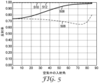
図5は、標準的なモデル化技法を用いてモデル化されたMOF前面部分反射体14の強く非対称的な実施形態の、空気中の光についての、第1と第2の軸の可視光平均反射率対入射角を示す。図5に示す反射率を有するMOF前面部分反射体14は、標準的フィルムテンターなどの拘束一軸配向を用いて、coPEN/PMMA共押出多層フィルムを使用して形成することができる。
FIG. 5 is a first and second axis visible light average for light in air for a strongly asymmetric embodiment of the MOF front
約300層を使用すると、図5に示す反射率は、y-z平面内及びx-z平面内に配置された偏光ベクトルを用いて、400~700nmの光について、達成することができる。coPENのマイクロ層の屈折率は、nx1=1.82、ny1=1.61、及びnz1=1.52である。そして、PMMAのマイクロ層の屈折率は、nx2=ny2=nz2=1.49である。曲線506は、図3の入射平面322について、p偏光の反射率を表し、曲線508は、図3の入射平面312について、s偏光の反射率を表す。曲線510及び512は、それぞれ、図3の入射平面312及び322について、p偏光及びs偏光の反射率を表す。反射率値は、多層フィルムからの反射、及び空気/フィルムの境界における表面反射を含む。
Using about 300 layers, the reflectance shown in FIG. 5 can be achieved for light between 400 and 700 nm with polarization vectors placed in the yz and xz planes. The refractive indices of the coPEN microlayers are n x1 =1.82, n y1 =1.61, and n z1 =1.52. The refractive index of the PMMA microlayer is then n x2 =n y2 =n z2 =1.49.
屈折率nz2は、nz1よりわずかに低く、図3の入射平面322(曲線506)のp偏光反射率は、図5に図示されているように、入射角の増加とともに、減少する。図5に示すように、s偏光の反射率は、実質的に入射角の関数として増加する。要約すると、図4及び図5を参照すると、ny1、nx1、及びnz1の高屈折率材料値間の範囲において、低屈折値材料の屈折率値を選択することにより、s偏光及びp偏光の相対強度は、角度の関数として制御され得る。このようにして、図1の革新的物品10の観測された色の角度制御を達成することができる。
Refractive index nz2 is slightly lower than nz1 , and the p-polarized reflectance at plane of incidence 322 (curve 506) in FIG. 3 decreases with increasing angle of incidence, as illustrated in FIG. As shown in FIG. 5, the reflectivity for s-polarized light increases substantially as a function of angle of incidence. In summary, referring to FIGS. 4 and 5, by selecting the refractive index values of the low refractive value material in the range between the high refractive index material values of n y1 , n x1 , and n z1 , s-polarized and p The relative intensity of polarized light can be controlled as a function of angle. In this way, angular control of the observed color of the
いくつかの実施形態では、MOF前面部分反射体14はまた、傾斜した反射及び透過スペクトルを有する。いくつかの実施形態では、前面部分反射体14は、利用可能な偏光状態、又は任意の入射平面における非偏光のいずれかについて、両方の入射平面において、入射光の青色傾斜透過スペクトルを有する。「傾斜した」透過スペクトルのいくつかの特性を図6及び図7に示す。
In some embodiments, the MOF front
図6は、可視波長範囲の光に対する人間の目の応答について、広く受け入れられているRGB等色関数(CIE 1931)を示す。プロットは、可視波長領域を、青色、緑色、及び赤色の人間の知覚に対応する特定の波長域に分離する。傾斜スペクトル特性を定義する便宜上、可視波長範囲の青色部分、緑色部分、及び赤色部分(青色については420nm~475nm、緑色については505nm~610nm、赤色については555nm~635nm)に対応する、RGB等色関数の半値幅を使用する。ビン平均と呼ばれる、所与のスペクトル特性(透過、反射など)の各波長範囲(すなわち、ビン)内の平均の分析は、スペクトル傾斜の特性を提供する。 FIG. 6 shows the widely accepted RGB color matching functions (CIE 1931) for the human eye's response to light in the visible wavelength range. The plot separates the visible wavelength range into specific wavelength bands corresponding to human perception of blue, green, and red. For convenience in defining the tilted spectral characteristics, RGB equivalence corresponding to the blue, green, and red portions of the visible wavelength range (420 nm-475 nm for blue, 505 nm-610 nm for green, and 555 nm-635 nm for red). Use the half width of the function. Analysis of the average within each wavelength range (ie, bin) of a given spectral characteristic (transmission, reflection, etc.), called the bin average, provides a characteristic of spectral tilt.
図7A~図7Eは、3つの可視波長ビンの各々からの相対的ビン値を比較することによって、スペクトル傾斜(又は傾斜の欠如)の定義を示す。この場合のビン値は、各波長範囲における透過値の平均である。本発明者等は、ビン間の範囲を、最大ビン値を3ビン平均で除した値と、最小ビン値を3ビン平均で除した値の差として、定義する。ビン間の範囲が15%を超えると、スペクトルは傾斜しているとみなされ、その色特性は、ビン値の最大値を3ビン平均で除した値を有するビンの色によって与えられる色特性を有する。ビン間の範囲が15%未満であるときは、スペクトルは、無彩色特性を有する、一定(非傾斜)とみなされる。傾斜が決定されるスペクトルは透過スペクトル又は反射スペクトルであり得ることが理解される。 Figures 7A-7E illustrate the definition of spectral tilt (or lack of tilt) by comparing the relative bin values from each of the three visible wavelength bins. The bin value in this case is the average of the transmission values in each wavelength range. We define the inter-bin range as the difference between the maximum bin value divided by the 3-bin average and the minimum bin value divided by the 3-bin average. If the bin-to-bin range exceeds 15%, the spectrum is considered to be tilted and its color characteristic is given by the color of the bin having the maximum bin value divided by the 3-bin average. have. When the range between bins is less than 15%, the spectrum is considered constant (non-tilted), with achromatic properties. It is understood that the spectrum for which the slope is determined can be the transmission spectrum or the reflection spectrum.
表2は、図7A~図7Eに示されるスペクトルの、この定量的定義を示す。

適切な傾斜及び色特性を有する傾斜透過スペクトルは、共押出ポリマーマイクロ層が、所望の屈折率関係及び所望の反射率特性をもたらすのに好適な条件下で配向されている場合であっても、無彩色(非傾斜)多層構造で生成されるスペクトルにわたり、コリメートのレベルを著しく上げることができる(すなわち、入射角の増加とともに、特定の可視波長範囲で、可視光反射が増加する)。加えて、多層干渉反射体からのスペクトル反射帯域は、入射角が増加すると、より短い波長に移動することが理解される。 A sloped transmission spectrum with appropriate slope and color characteristics is obtained even when the coextruded polymer microlayers are oriented under suitable conditions to provide the desired refractive index relationship and desired reflectance characteristics. Across the spectrum produced by achromatic (non-tilted) multilayer structures, the level of collimation can be significantly increased (ie, visible light reflection increases in certain visible wavelength ranges with increasing angle of incidence). Additionally, it can be seen that the spectral reflection band from the multilayer interference reflector moves to shorter wavelengths as the angle of incidence increases.
図8~図10は、その構成要素の屈折率関係に起因する、角度とともに増加する反射率と、入射角が増加すると、より短い波長に移動する傾斜透過スペクトルとの両方を有するポリマー多層光学フィルムの組み合わせ効果を図示する。なお、これらの図における反射率の値は単なる例示であること、及び、低損失ポリマーはT%=100%-R%を想定することを可能にすることに留意されたい。達成可能なフィルム設計のスペクトルが本明細書に提示される。図8~図10の各々において、透過スペクトルは、選好された軸に沿った偏光、又はランダム偏光のいずれかとすることができる。 8-10 show polymeric multilayer optical films that have both a reflectance that increases with angle and a tilted transmission spectrum that shifts to shorter wavelengths as the angle of incidence increases due to the refractive index relationships of its constituents. illustrates the combined effect of It should be noted that the reflectance values in these figures are merely exemplary and that a low loss polymer allows one to assume T%=100%-R%. A spectrum of achievable film designs is presented herein. In each of FIGS. 8-10, the transmission spectrum can be either polarized along a preferred axis or randomly polarized.
図8は、2つの入射角における透過スペクトルのブロック図表現である。この表現は、共押出ポリマーマイクロ層が、p偏光についてブリュースター角が存在しない、したがって、p偏光の反射率は入射角とともに顕著に増加する屈折率関係を生成するために好適な条件下で配向されている例を示す。あるいは、入射角の増加とともに、増加する、より一般的なs偏光反射率のケースを表してもいる。 FIG. 8 is a block diagram representation of the transmission spectrum at two angles of incidence. This expression means that the coextruded polymer microlayers are oriented under conditions suitable to produce a refractive index relationship in which the Brewster angle does not exist for p-polarized light and therefore the reflectance of p-polarized light increases significantly with angle of incidence. Here are some examples: Alternatively, it represents the more general case of s-polarization reflectance increasing with increasing angle of incidence.
図8では、角度の変化にともなうスペクトルの光学的厚さ(反射帯域の波長位置)の青方移動は、この広帯域スペクトルの横方向移動が可視光の透過に影響を及ぼさない(可視光は、システム要件に応じて、約400~700nm、又は420~680nm、又は430~650nmと定義することができる)ため、コリメートの程度に影響を及ぼさない。可視光反射率の増加のみがコリメートプロセスに寄与する。 In FIG. 8, the blue shift of the spectral optical thickness (wavelength position of the reflection band) with change in angle indicates that this lateral shift of the broadband spectrum does not affect the transmission of visible light (the visible light is It can be defined as about 400-700 nm, or 420-680 nm, or 430-650 nm, depending on system requirements), so it does not affect the degree of collimation. Only an increase in visible light reflectance contributes to the collimation process.
ここで、交互ポリマー層について整合するz屈折率を有するポリマー多層光学フィルムについて、図9に示すp偏光のための概略傾斜(青色傾斜)スペクトルを考慮する。第1に、整合したz屈折率を有する多層干渉反射体は、入射角が増加するにつれて、帯域は、任意の他の多層干渉反射体と同様、より短い波長に移動するが、p偏光についての実質的な反射率の増加も減少も生じないことを想起されたい。帯域幅は十分に広いので、長波帯域は、対象とする全ての入射角について、可視スペクトルの縁部を越える。反射率の大きさは、p偏光の入射角につれて変化しないが、スペクトルの青色傾斜は、入射角が増加するにつれて、図9のスペクトルの可視平均透過率を減少させる。換言すれば、青色傾斜スペクトルの横方向移動は、スペクトル曲線が垂直方向に移動されていなくても、特定の波長の反射率を、角度とともに増加させる。このため、そのようなフィルムは、再生バックライトからの光をコリメートするように働くことができる。図9のスペクトルが一定であったならば(非傾斜)、実質的にコリメートは起こらない。 Now consider the schematic tilt (blue tilt) spectrum for p-polarized light shown in FIG. 9 for a polymeric multilayer optical film with matching z-index for alternating polymer layers. First, for multilayer interference reflectors with matched z-index, as the angle of incidence increases, the band shifts to shorter wavelengths, similar to any other multilayer interference reflector, but for p-polarization Recall that neither a substantial increase nor decrease in reflectance occurs. The bandwidth is wide enough that the long-wave band extends beyond the edges of the visible spectrum for all angles of incidence of interest. Although the magnitude of the reflectance does not change with the angle of incidence for p-polarized light, the blue tilt of the spectrum decreases the visible average transmittance of the spectrum of FIG. 9 as the angle of incidence increases. In other words, lateral shift of the blue tilt spectrum causes the reflectance of a particular wavelength to increase with angle, even though the spectral curve is not vertically shifted. As such, such films can serve to collimate light from a playback backlight. If the spectrum in FIG. 9 were constant (untilted), virtually no collimation would occur.
図10は、入射角の関数として、s偏光又はp偏光のいずれか、又はその両方について反射率が増加する屈折率関係を生成するように設計及び加工されたポリマーMOFの傾斜スペクトルを示す。図10から、ここで、コリメートは、スペクトルの角度移動と、入射角とともに起こるフィルムの反射率の増加との両方から生じることが分かる。いくつかの実施形態では、青色傾斜透過スペクトルについて図10に示す拡大されたコリメート効果は、MOFフィルム物品10の構成要素の光学特性の間の関係に応じて、青色から緑色、黄色、又は赤色までの色空間にわたって、図1のMOFフィルム物品10によって放射される光の色の制御された変化を生じさせるか、又は変化を生ぜずに無彩色白色を与えることができる。
FIG. 10 shows tilt spectra of polymer MOFs designed and engineered to produce refractive index relationships that increase reflectivity for either s-polarized light, p-polarized light, or both, as a function of angle of incidence. From FIG. 10, it can be seen that the collimation here results from both the angular shift of the spectrum and the increase in film reflectance that occurs with angle of incidence. In some embodiments, the expanded collimation effect shown in FIG. 10 for the blue tilted transmission spectrum ranges from blue to green, yellow, or red depending on the relationship between the optical properties of the components of
青色傾斜透過スペクトルを有するMOF前面部分反射体14は、MOF物品10の前面部分反射体として使用されるとき、赤色光、緑色光、及び青色光のコリメートを向上させることができる。青色傾斜反射体は、他の軸と比較して、1つの軸上で偏光された光に対してより高い透過率を有する非対称反射体であり得る。傾斜したスペクトルは、いずれかの軸に平行な偏光、又は非偏光透過光に関するものとすることができる。実質的に偏光された出力を必要とする任意の照明システムでは、フィルムの通過軸光が透過され、青色傾斜スペクトルを有するとき、最も高い効率が得られる。透過が全部の光透過を意味するにせよ、1つの軸のみに関わる透過を意味するにせよ、ビン値間の範囲が15%であるか、又は30%、又は100%、又は15%~100%、又は15%~50%である場合、傾斜はあり得る。青色の傾斜透過スペクトルは、垂直な入射角度、又は45°、50°、あるいは60°などの斜め透過角度であってもよい。斜角では、p偏光のスペクトル、又はs偏光のスペクトル、又はその両方は、青色傾斜であり得る。参照によりその全体が本明細書に組み込まれる米国特許公開第2014/0254124号に記載されている実施例は、コリメートを改善するように最適化することができる光学積層体及びフィルム構造を作製する方法を更に示す。
A MOF front
ここで図11Aを参照すると、いくつかの実施形態では、MOF前面部分反射体114は、選択された反射率及び透過特性を有する層114を提供するために、1つ以上のフィルム積層体又は層構造114A、114Bを含むことができる。前面部分反射体114は、間隔を置いて配置されているか、又は接触している2つ以上のフィルムを含むことができる。フィルム114A、114Bは、例えば任意の接着材層118などの任意の好適な技術を用いて取り付けることができる。層118には、任意の好適な接着材、例えば、感圧接着材(3M Optically Clear Adhesivesなど)、及び紫外線硬化性接着材(Uvx-4856など)を使用することができる。いくつかの実施形態では、フィルム間の接着材層118は、屈折率整合流体に置き換えることができえる。
Referring now to FIG. 11A, in some embodiments, MOF front
フィルム114A、114Bは、本明細書に記載する任意の好適なフィルムを含むことができ、同様の光学特性を有するものとするか、又は異なる光学特性を提供する異なる構造とすることができる。例示的一実施形態では、MOF前面部分反射体114は、1つの平面内に通過軸を有する第1の非対称反射フィルム114Aから形成され、フィルム114Bは、第1のフィルム114Aの通過軸と平行でない第2の平面内に通過軸を有する第2の非対称反射フィルムを含むことができる。この非平行関係は、2つの通過軸面の間に任意の好適な角度を形成することができる。いくつかの実施形態では、通過軸面はほぼ直交することができる。このような関係は、MOF前面部分反射体114の通過軸における高い反射率を提供するであろう。
別の例では、MOF前面部分反射体114は非対称反射フィルム114Aを含んでもよく、フィルム114Bは、3M Co.(St.Paul,MN)から商品名Brightness Enhancement Film(BEF)で入手可能なものなどのプリズム明度向上フィルムを含んでもよい。いくつかの実施形態では、BEF 114Bは、非対称反射フィルム114Aに対して、BEF 114Bが、非対称フィルム114Aのコリメート面に直交する平面内で透過光をコリメートするように、配向されてもよい。
In another example, the MOF front
図11AのMOF前面部分反射体114は、いくつかの実施形態では、2つのフィルム114A、114Bを含むものとして描かれているが、前面部分反射体114は3つ以上のフィルムを含むことができる。例えば、3層前面部分反射体は、3層の反射型偏光子(DBEF又はAPFなど)を使用して製作することができる。3つの層が、第2の層の偏光軸が第1の層の偏光軸に対して45°になり、第3の層の偏光軸が第1の層の偏光軸に対して90°になるように配置された場合、結果として生じる前部反射体は、垂直な入射光の約75%を反射する。他の層間回転角度を用いて、異なるレベルの反射を達成することができる。ほぼ直交する通過軸を有する2つの反射型偏光子間の複屈折(偏光回転)層又は散乱層もまた、前面反射体として使用される、制御された反射率の程度を有する反射フィルムを作り出すことができる。
Although the MOF partial
本開示のMOF前面部分反射体はまた、反射体の1つ以上の表面内又は表面上に配置された光学素子を含むことができる。例えば、図11Bは、MOF前面部分反射体124の別の実施形態の一部分の概略断面図である。前面部分反射体124は、上述の任意の好適なフィルム又は層を含むことができる第1の主表面123及び第2の主表面125を有するフィルム積層体124Aを含む。複数の光学素子130は、第1の主表面123上又はその面内に位置付けられる。光学素子は、第1の主表面123のみに配置されているように描かれているが、第2の主表面125上、又は第1の主表面123と第2の主表面125の両方の上に配置することができる。例えば、マイクロスフィア、プリズム、コーナーキューブ、レンズなど、任意の好適な光学素子は、フィルム124A上又はフィルム124A内に配置することができる。光学素子は、屈折素子、回折素子、拡散素子などであり得る。この実施形態では、光学素子130は、フィルム124Aによって透過される光をコリメートすることができる。他の実施形態では、光学素子130は、光学素子130の位置決めに応じて、フィルム124Aに入射するか、又はフィルム124Aから出る光を拡散することができる。
The MOF front partial reflectors of the present disclosure can also include optical elements disposed in or on one or more surfaces of the reflector. For example, FIG. 11B is a schematic cross-sectional view of a portion of another embodiment of a partial MOF
光学素子130は、フィルム124Aの主表面123上に配置するか、又は主表面123に少なくとも部分的に埋め込むことができる。更に、フィルム124Aは、任意の好適な技術、例えば、ビーズコーティングESRを製作するための本明細書に記載した技術を用いて製作することができる。
光学素子はまた、フィルムに近接して配置された隅部又は基材上に配置することもできる。例えば、図11Cは、前面部分反射体134の別の実施形態の一部分の概略断面図である。反射体134は、フィルム134Aと、フィルム134Aに近接して配置された利得拡散体138と、を含む。フィルム134Aは、前面部分反射体に関して本明細書に記載する任意のフィルム及び/又は層を含むことができる。利得拡散体138は、第1の主表面139Aと第2の主表面139Bとを有する基板139と、基板139の第2の主表面139B上又はその中に配置された複数の光学素子140とを含む。任意の好適な光学素子140、例えば、図11Bの光学素子130を使用することができる。基板139は、任意の好適な光透過性基材を含むことができる。
The optical element can also be placed on a corner or substrate located close to the film. For example, FIG. 11C is a schematic cross-sectional view of a portion of another embodiment of partial
図11Cに示す実施形態では、利得拡散体139の第1の主表面139Aは、偏光フィルム134Aに近接して位置付けられる。拡散体139は、フィルム134Aと接触しているか、又はフィルム134Aに取り付けられたフィルム134Aから間隔を置くように、フィルム134Aに近接して配置することができる。任意の好適な技法、例えば、光学接着材の使用、によって、拡散体139をフィルム134Aに取り付けることができる。拡散体139として、任意の好適な利得拡散体を使用することができる。いくつかの実施形態では、光学素子140は、素子140が基板139と偏光フィルム134Aの間にあるように、基材139の第1の主表面139A上に配置することができる。
In the embodiment shown in FIG. 11C, first
本開示の非対称反射フィルムは、米国特許第6,783,349号(Neavinら)、発明の名称APPARATUS FOR MAKING MULTILAYER OPTICAL FILMS記載の技術を用いて製造することができる。例えば、図12A~図12Bは、本開示の非対称反射フィルムを作製するための方法の一実施形態を示す。好適に異なる光学特性を有するように選択された材料900及び902は、それらの溶融及び/又はガラス転移温度を超えて加熱され、多層供給ブロック904に供給される。典型的には、溶融及び初期供給は、各材料の押出装置を使用して達成される。例えば、材料900は、押出装置901に供給することができ、材料902は押出装置903に供給され得る。供給ブロック904から出るのは、多層フローストリーム905である。層増倍装置906は、多層フローストリームを分割し、次いで、1つのストリームを方向転換し、第2の上に「積層」して、押し出された層の数を増倍する。非対称増倍装置は、積層体全体を通じて層厚の偏差を導入する押出装置と共に使用されると、多層フィルムが可視光スペクトルの所望の部分に対応する層対を有し、所望の層厚勾配を提供することを可能にするように、層厚の分布を広げることができる。所望であれば、スキン層911は、スキン層供給ブロック910に樹脂908(スキン層用)を供給することによってフィルムに導入されてもよい。
Asymmetric reflective films of the present disclosure can be manufactured using the techniques described in US Pat. No. 6,783,349 (Neavin et al.), entitled APPARATUS FOR MAKING MULTILAYER OPTICAL FILMS. For example, Figures 12A-12B illustrate one embodiment of a method for making an asymmetric reflective film of the present disclosure.
多層供給ブロックは、フィルム押出ダイ912に供給する。好適な供給ブロックは、例えば、米国特許第3,773,882(Schrenk)及び同第3,884,606(Schrenk)に記載されている。一例として、押出温度は、約295℃とし、各材料について約10-150kg/時の供給速度とすることができる。いくつかの実施形態では、スキン層911は、供給ブロック及びダイを通過する際に、フィルムの上面及び下面に流れることができる。これらの層は、壁付近に見られる大きな応力勾配を消散させる働きをし、光学層のより滑らかな押し出しをもたらす。各スキン層の典型的な押出速度は、2~50kg/時間(総スループットの1%~40%)である。スキン材料は、光学層のうちの1つと同じ材料であってもよく、又は異なる材料であってもよい。ダイを出る押出物は、典型的には溶融形態である。
A multi-layer feedblock feeds the film extrusion die 912 . Suitable feedblocks are described, for example, in US Pat. Nos. 3,773,882 (Schrenk) and 3,884,606 (Schrenk). As an example, the extrusion temperature can be about 295° C. with a feed rate of about 10-150 kg/hr for each material. In some embodiments, the
押出物は、ピニングワイヤ914を通過して、回転するキャスティングホイール916上で冷却される。ピニングワイヤは、押出物をキャスティングホイールにピン留めする。広い範囲の角度にわたって透明なフィルムを実現するために、キャスティングホイールを低速で運転することによってフィルムをより厚くすることができ、それは、反射帯域をより長い波長の方に向かって移動させる。フィルムは、所望の光学的特性及び物理的特性によって決定される比で延伸することによって配向される。
The extrudate passes through pinning
長手方向延伸は、プルロール918によって行うことができる。横方向の延伸は、テンターオーブン920で行うことができる。所望であれば、フィルムは、2軸方向に同時に配向することができる。約3~4:1の延伸比を選好されてもよいが、所与のフィルムについて、1:1まで下げても、6:1まで上げてもよい。延伸温度は、使用される複屈折ポリマーの種類に依存するが、ガラス転移温度よりも2℃~33℃(5°F~60°F)が、一般に適切な範囲である。フィルムは、典型的には、フィルム内の最大結晶化度を付与し、その収縮を低減するために、テンターオーブンの最後の2つのゾーン922で、熱硬化される。テンター内のフィルム破断を引き起こすことなく、可能な限り高い熱硬化温度を用いることにより、加熱されたエンボス加工ステップの間の収縮が低減される。テンターレールの幅を約1%~4%だけ減少させると、フィルムの収縮を低減することになる。フィルムが熱硬化ではない場合、熱収縮特性は最大化され、これは、いくつかのセキュリティパッケージング適用において望ましいこともある。フィルムは、巻き取りロール924上に収集することができる。
Longitudinal stretching can be done by pull rolls 918 . Lateral stretching can be done in a
いくつかの適用では、多層フィルムの光学層に2つを超える異なるポリマーを使用することが望ましいこともある。そのような場合、樹脂ストリーム900及び902と同様の手段を用いて追加の樹脂ストリームを供給することができる。供給ブロック904に類似した2つを超える層タイプを配分するために適切な供給ブロックを使用することができる。
In some applications it may be desirable to use more than two different polymers in the optical layers of multilayer films. In such cases, additional resin streams can be supplied using means similar to
図12Bは、勾配プレート930を含む供給ブロック904の一実施形態の概略斜視図を示す。勾配プレート930内に存在するのは、少なくとも2つの流路、第1の流路932、及び第2の流路934である。流路は、勾配プレート930と供給チューブプレート940との組み合わせによって画定される。
FIG. 12B shows a schematic perspective view of one embodiment of
勾配プレート930では、それぞれの流路は、その断面が、例えば、円形、正方形、又は正三角形などの対称中心軸を有するように機械加工される。機械加工を容易にするために、正方形の断面流路を使用することが好ましい。各流路に沿って、断面積は一定でもよく、又は変化してもよい。この変化は、面積の増加又は減少であってもよく、減少する断面は、典型的には「テーパ」と呼ばれる。流路の断面積の変化は、多層光学フィルムの層厚分布に影響を及ぼす適切な圧力勾配を提供するように設計することができる。したがって、勾配プレートは、異なる種類の多層フィルム構造のために、変更することができる。
In
流路の断面積が一定のままである場合、層の厚さ対層の数のプロットは、非線形であり、減少する。所与のポリマーの流れについて、少なくとも1つの断面テーパプロファイルが存在し、これは、層の数に対する層の厚さの直線的な減少依存性をもたらし、これはときに好ましい。テーパプロファイルは、当業者が、問題のポリマーのレオロジーデータ、及び当該技術分野において既知のポリマー流動シミュレーションソフトウェアを用いて発見することが可能であり、ケースごとに計算されるべきである。 If the channel cross-sectional area remains constant, the plot of layer thickness versus number of layers is non-linear and decreases. For a given polymer flow, there is at least one cross-sectional taper profile, which results in a linearly decreasing dependence of layer thickness on layer number, which is sometimes preferred. The taper profile can be found by one skilled in the art using the rheological data of the polymer in question and polymer flow simulation software known in the art, and should be calculated on a case-by-case basis.
再び図12Bを参照すると、供給ブロック904は、各々が流路932及び934とそれぞれ流体連通して硬化された、導管942の第1のセット及び導管944の第2のセットを有する、供給チューブプレート940を更に含む。本明細書で使用するとき、「導管」は、「側路チューブ」とも呼ばれる。導管942及び944の近くには、導管内を流れる樹脂に熱を与えるために使用される、軸方向のロッドヒータ946がある。所望であれば、軸方向ロッドヒータの長さに沿ったゾーンで温度を変化させることができる。各導管は、拡張セクション及びスロットセクションを有する、それ自体の対応するスロットダイ956に供給する。拡張セクションは、典型的には、供給チューブプレート940内に位置する。所望であれば、スロットセクションは、スロットプレート950内に置くことができる。本明細書で使用するとき、用語「スロットダイ」は、「層スロット」と同義である。導管942の第1のセットは、導管944の第2のセットとインターリーブされて、交互層を形成する。
Referring again to FIG. 12B,
使用時に、例えば、樹脂A及び樹脂Bは、流路932及び934に直接送られる。溶融ストリームA及び溶融ストリームBが勾配プレート930内の流路を通って移動するにつれて、各溶融ストリームは導管によって吹き出される。導管942と944は交互配置されているため、例えばABABABなどの交互層の形成を開始する。各導管は、実際の層の形成を開始するために、それ自体のスロットダイを有する。スロットダイから出る溶融ストリームは、複数の交互層を含む。溶融ストリームは、圧縮セクション(図示せず)に供給され、ここで層が圧縮され、横方向に均一に広がる。保護境界層(PBL)として知られる特別な厚い層は、光学多層積層体のために使用される溶融ストリームのいずれかから供給ブロック壁に最も近いように供給されてもよい。PBLはまた、供給ブロック後に別個の供給流によって供給され得る。PBLは、壁応力及びその結果生じる可能性のある流動不安定性の影響から、より薄い光学層を保護するように機能する。
In use, for example, resin A and resin B are sent directly to
いくつかの実施形態では、本開示の非対称反射フィルムは、増倍装置(例えば、増倍装置906)を使用せずに製造することができる。層増倍装置は、多数の光学層の生成を大幅に単純化するが、できあがった各層パケットに対し、パケットごとに同じではない、歪みを与える可能性がある。この理由のため、供給ブロック内で生成された層の層厚さプロファイルの調整は、パケットごとに同じではない、すなわち、すべてのパケットを、スペクトルの乱れのない均一で滑らかなスペクトルを生成するように同時に最適化することはできない。したがって、最適プロファイルと低透過を有する色反射体を、増倍装置を用いて製造されたマルチパケットフィルムを使用して、作製するのは困難である可能性がある。供給ブロック内で直接生成された単一パケット内の層の数が、十分な反射率をもたらさない場合は、2つ以上のそのようなフィルムを張り合わせて、反射率を高めることができる。 In some embodiments, the asymmetric reflective films of the present disclosure can be manufactured without the use of a multiplication device (eg, multiplication device 906). Layer multipliers greatly simplify the production of multiple optical layers, but can impart distortions to each resulting layer packet that are not the same from packet to packet. For this reason, the adjustment of the layer thickness profile of the layers produced within the feedblock is not the same for each packet, i. cannot be optimized at the same time. Therefore, it can be difficult to produce color reflectors with optimum profiles and low transmission using multipacket films produced with intensifiers. If the number of layers in a single packet produced directly in the feedblock does not provide sufficient reflectivity, two or more such films can be laminated together to increase reflectivity.
増倍装置が図12Aの方法から除去されるとき、軸方向ロッドヒータ946を使用して、例えば、米国特許第6,783,349号に更に記載されているように、共押出ポリマー層の層厚値を制御することができる。このような軸方向ロッドヒータは、供給ブロック内を一定温度に維持するため、かつ、最大約40℃の温度勾配を作り出すために利用することができる。いくつかの実施形態では、軸方向のロッドヒータは、供給ブロックを貫通する孔内に配置され、好ましくは、各側路チューブがスロットダイに供給する点を通る仮想線のごく近くに配向される。より好ましくは、第1のポリマーと第2のポリマーとの共押出の場合、軸方向ロッドヒータのための孔は、各側路チューブがスロットダイに供給する点を通る仮想線の近くで、かつ、第1のポリマーを運ぶ側路チューブと第2のポリマーを運ぶ側路チューブから等距離の所に位置する。更に、軸方向ロッドヒータは、好ましくは、その長さに沿った電気抵抗の変化によって、又はマルチゾーン制御によって、又は当該技術分野において既知のその他の手段によって、その長さに沿って温度勾配又は多数の離散的な温度を提供することができるタイプである。そのような軸方向ロッドヒータは、層厚さ及び勾配層厚分布を制御することができ、これは、例えば、米国特許第6,157,490号(Wheatleyら)、発明の名称OPTICALFILM WITH SHARPENED BANDEDGE、及び米国特許出願第6,531,230号、発明の名称COLOR SHIFTING FILMに記載されている反射帯域の位置及びプロファイルの制御に特に重要である。
When the intensifier is removed from the method of FIG. 12A,
供給ブロック904は、フィルム積層体内の全ての層が軸方向ロッドヒータ946によって直接制御されるように構成される。層厚さプロファイルは、任意の好適な厚さ測定技術、例えば、原子間力顕微鏡(AFM)、透過電子顕微鏡法、又は走査電子顕微鏡法を用いて、プロセス中に監視することができる。層厚さプロファイルはまた、任意の好適な技術を用いて光学的にモデル化することができ、そこで、軸方向ロッドヒータは、測定された層プロファイルと所望の層プロファイルとの間の差に基づいて調整することができる。
層プロファイルはまた、一般的にAFMほど正確ではないが、光学スペクトルを積分することによって迅速に推定することができる(-Log(1-R)対波長スペクトルを積分する)。これは、層厚さプロファイルが層数に対して単調に増加又は減少することを条件として、層厚さプロファイルの導関数から反射体のスペクトル形状を得ることができるという一般的な原理によるものである。 The layer profile can also be estimated quickly by integrating the optical spectrum (-Log(1-R) vs. integrating the wavelength spectrum), although it is generally not as accurate as AFM. This is due to the general principle that the spectral shape of the reflector can be obtained from the derivative of the layer thickness profile, provided that the layer thickness profile is monotonically increasing or decreasing with layer number. be.
層厚さプロファイル制御の基本プロセスは、典型的には、目標の層厚さプロファイルと測定した層プロファイルの差に基づく軸ロッドゾーン電力設定の調整を含む。各供給ブロックゾーンにおける層厚値を調整するために必要とされる軸ロッド電力の増加を、そのヒーターゾーン内で、その結果として得られる、生成された層の厚さ変化の、ナノメートル当たりの熱入力のワット数に関して校正してもよい。例えば、275層に対して24個の軸ロッドゾーンを使用すると、スペクトルの微調整制御が可能である。いったん校正されたならば、目標プロファイルと測定プロファイルが与えられれば、必要な電力調整を計算することができる。この手順は、2つのプロファイルが収束するまで繰り返される。 The basic process of layer thickness profile control typically involves adjusting the axial rod zone power settings based on the difference between the target layer thickness profile and the measured layer profile. The increase in axial rod power required to adjust the layer thickness value in each feed block zone, within that heater zone, of the resulting layer thickness change produced per nanometer It may be calibrated for wattage of heat input. For example, using 24 axial rod zones for 275 layers allows fine tuning control of the spectrum. Once calibrated, the required power adjustments can be calculated given the target and measured profiles. This procedure is repeated until the two profiles converge.
例えば、屈折率nx1=1.82、ny1=1.61、nz=1.50を有するcoPENと、全ての方向について屈折率n2=1.57を有するPCTGとポリカーボネート混合物を使用して、上記技術に従って275層のフィルムを作製した。通過軸上の60°入射角でp偏光の測定された透過スペクトルを、図13に曲線1002として示す。また、ブロック軸の透過も、曲線1004として示す。ブロック軸と通過軸の両方のスペクトルは、非常に広い帯域にわたって比較的一定である透過を有することに留意されたい。
For example, using coPEN with refractive indices nx = 1.82, ny = 1.61, nz = 1.50 and PCTG and polycarbonate blends with refractive indices n = 1.57 for all directions, the
再び図1を参照すると、いくつかの実施形態では、MOF物品10内に拡散が与えられる。そのような拡散は、物品10内の光のより多くの角度混合を与えることができ、それは、光を拡散させるのに役立ち、出力面を通して構造から外に向けられた光に、より均一性を与えることができる。拡散は、前面部分反射体14と後部反射体12のいずれか、あるいは両方によって、又は、前面部分反射体14と後部反射体12との間に配置された1つ以上の層によって、与えることができる。
Referring again to FIG. 1, diffusion is provided within the
いくつかの実施形態では、拡散は半鏡面拡散を含むことができる。本明細書で使用するとき、用語「半鏡面反射体」は、後方散乱よりも実質的に、より前方の散乱を反射する反射体を指す。同様に、用語「半鏡面拡散体」は、入射光の実質的に大部分について、入射光の垂直な成分を反転させない拡散体を意味し、すなわち、光は、前方(z)方向に実質的に透過し、xとy方向にある程度散乱する。換言すれば、半鏡面反射体及び拡散体は、実質的に前方方向に光を向け、したがって、全ての方向に光線を等しく方向転換するランバート構成要素とは非常に異なる。半鏡面反射体及び拡散体は、比較的広い散乱角を示すことができ、あるいは、そのような反射体及び拡散体は、鏡面方向の外側にわずかな量の光偏向を示すことができる。例えば、米国特許第8,608,363号及び同第9,091,408号(Weberら)、発明の名称RECYCLING BACKLIGHTS WITH SEMI-SPECULAR COMPONENTSを参照されたい。 In some embodiments, diffusion can include semi-specular diffusion. As used herein, the term "semi-specular reflector" refers to a reflector that reflects substantially more forward scatter than backscatter. Similarly, the term "semi-specular diffuser" means a diffuser that does not invert the normal component of incident light for substantially the majority of the incident light, i.e., the light is directed substantially in the forward (z) direction. and scatters to some extent in the x and y directions. In other words, semi-specular reflectors and diffusers direct light in a substantially forward direction, and thus are very different from Lambertian components, which redirect light rays equally in all directions. Semi-specular reflectors and diffusers can exhibit relatively wide scattering angles, or such reflectors and diffusers can exhibit a small amount of light deflection outward in the specular direction. See, for example, US Pat. Nos. 8,608,363 and 9,091,408 (Weber et al.), entitled RECYCLING BACKLIGHTS WITH SEMI-SPECUAL COMPONENTS.
任意の好適な半鏡面性材料を、本開示の前面反射体及び後部反射体に使用することができる。例えば、半鏡面後部反射体12は、高反射率拡散反射体上に部分透過性の鏡面反射体を含むことができる。好適な鏡面反射体としては、ESR(3M Companyから入手可能)及び本明細書に記載の他の鏡面反射体が挙げられる。好適な高反射率拡散反射体としては、EDR IIフィルム(3Mから入手可能)、W.L.Gore&Associates,Inc.から入手可能なものなどの多孔質ポリテトラフルオロエチレン(PTFE)フィルム、Labsphere,Inc.から入手可能なSpectralon反射率材料、Furukawa Electric Co.,Ltd.から得られるMCPET高反射率フォームシーティング、Mitsui Chemicals,Inc.から入手可能なWhite Refstarフィルムなどが挙げられる。
Any suitable semi-specular material can be used for the front and back reflectors of the present disclosure. For example,
別の実施形態では、半鏡面後部反射体12は、高反射率鏡面反射体上の部分的ランバート拡散体を含むことができる。あるいは、高反射率鏡面反射体上の前方散乱拡散体は、半鏡面後部反射体を提供することができる。
In another embodiment, the semi-specular back
いくつかの実施形態では、MOF前面部分反射体14は、後部反射体12のような構成で半鏡面性にすることができる。例えば、部分反射ランバート拡散体は、部分鏡面反射体と組み合わせることができる。あるいは、前方散乱拡散体は、部分鏡面反射体と組み合わせることができる。更に、前面部分反射体14は、前方散乱部分反射体を含むことができる。他の実施形態では、上述の前面反射体のいずれかを組み合わせて、半鏡面前面反射体を提供することができる。
In some embodiments, the MOF front
市販の高反射率フィルムの例としては、東レフィルムからの微小空隙配向ポリエステル(PET)フィルムのような拡散フィルム、及び3M Co.からのESRのような鏡面反射体などが挙げられるが、これらに限定されない。微小空隙フィルムは、約95%反射性(透過率は約4%)であり、厚さ約0.2mmである。ESRは、約99%反射性であり、厚さわずか約0.07mmである。微小空隙PET反射率は、空気と配向ポリエステルとの屈折率差約1.65によって生じる。ESRは、配向されたPENとPMMAの多層であり、垂直入射における屈折率差は約0.26である。そのため、ESRは、はるかに小さい屈折率差を有するが、それは、非常に薄い構造で、少なくとも99%の反射性を有するものとすることができる。 Examples of commercially available high reflectance films include diffusion films such as microvoid oriented polyester (PET) films from Toray Films, and 3M Co., Inc.; Specular reflectors, such as ESR from ESR, and the like, but are not limited to these. The microvoided film is approximately 95% reflective (transmittance is approximately 4%) and is approximately 0.2 mm thick. ESR is about 99% reflective and only about 0.07 mm thick. Microvoided PET reflectance is caused by a refractive index difference of about 1.65 between air and oriented polyester. The ESR is an oriented PEN and PMMA multilayer with a refractive index difference of about 0.26 at normal incidence. Therefore, although ESR has a much smaller refractive index difference, it can be at least 99% reflective in very thin structures.
ブロック軸反射率が高い偏光フィルムが所望される場合、屈折率は1つの軸に沿って整合させる必要があるため、材料間の屈折率差は材料の複屈折によって制限される。PENの場合、複屈折は約0.25であるため、拡散反射偏光子は、約0.25の屈折率差を有するブレンドポリマーで作製することができる。したがって、これらの構造は、95%反射性とするためには、空隙PET反射体よりもはるかに厚くなければならない。高複屈折材料は、しばしば、アクリル材料のような等方性低屈折率材料と比較して、比較的高い吸収係数を有するので、反射率は、そのような厚いフィルムにおける吸収損失によって制限される可能性がある。多層構造は、鏡面性であるという更なる利益を有し、これは中空キャビティを横切る光の輸送を向上させることができる。コレステリック反射体はまた、ブラッグ反射体の部類であり、非常に反射的であり、本質的に偏光する。円偏光を線形に変換するために、1/4波長リターダプレートが必要とされる。損失を最小限まで低減するために、光がリターダを1回だけ通過するように、リターダをキャビティの外面に配置することができる。 If a polarizing film with high block-axis reflectance is desired, the refractive indices must be matched along one axis, so the refractive index difference between materials is limited by the birefringence of the materials. For PEN, the birefringence is about 0.25, so a diffusely reflecting polarizer can be made of blended polymers with a refractive index difference of about 0.25. Therefore, these structures must be much thicker than voided PET reflectors to be 95% reflective. Since high birefringence materials often have relatively high absorption coefficients compared to isotropic low refractive index materials such as acrylic materials, reflectivity is limited by absorption losses in such thick films. there is a possibility. Multilayer structures have the additional benefit of being specular, which can improve the transport of light across the hollow cavity. Cholesteric reflectors are also a class of Bragg reflectors and are highly reflective and inherently polarizing. A quarter-wave retarder plate is required to convert circularly polarized light to linear. To reduce losses to a minimum, the retarder can be placed on the outer surface of the cavity so that light passes through the retarder only once.
銀の金属製後部反射体12は、腐食耐性のためにコーティングされている場合、95%反射性となり得る。銀及び他の金属、最も目立つのはアルミニウムであるが、誘電性薄膜でコーティングされたならば、それらにより、より高い反射率を達成することができる。ワイヤグリッド偏光子は、適切に構築されたならば、ブロック軸について、比較的高い反射率を有することができる。(例えば、米国特許第6,122,103号を参照のこと。)通過軸については、多少の部分反射率があり、これは、多層反射フィルム積層体を追加すると増加させることができる。
The silver
MOF前面部分反射体14は、後部反射体12の上に連続的又は不連続的のいずれかであるように形成することができる。前面部分反射体14は、後部反射体12にわたって空間的に不変とすることができ、あるいは、前面部分反射層は、後部反射体12にわたる拡散性の勾配を含むことができる。また、半鏡面反射を与える1つ以上の構造でパターン化された高反射性後部反射体12を利用することもできる。好適な形状は、例えば、波状形状の高反射率鏡面後部反射体を使用することによって形成することができる。
The MOF front
本発明の実施形態を以下の非限定的な実施例を参照して、以下に記載する。
以下の実施例のそれぞれについて、MOF物品10(図1)内の各要素又は要素の組み合わせの反射スペクトルは、Berriman4×4マトリックス多層光学応答計算エンジンを使用して計算された。このような計算のための入力パラメータとしては、光学繰り返し単位(ORU)の層厚さプロファイル、並びに複屈折性の第1の材料層PENの波長依存性屈折率値(nx、ny、及びnz)、及び等方性の(niso:nx=ny=nz)第2材料層PHEN13及びPMMAのそれらの値が含まれる。
実施例1-青色から銀色へ:MOF物品フィルム構造
Embodiments of the invention are described below with reference to the following non-limiting examples.
For each of the following examples, the reflectance spectrum of each element or combination of elements in MOF article 10 (FIG. 1) was calculated using a Berriman 4×4 matrix multilayer optical response calculation engine. Input parameters for such calculations include the layer thickness profile of the optical repeating unit (ORU) and the wavelength dependent refractive index values of the birefringent first material layer PEN (n x , n y , and n z ), and isotropic (n iso : n x =n y =n z ) second material layers PHEN13 and those values for PMMA.
Example 1 - Blue to Silver: MOF Article Film Construction
MOF素子12及び14を含むフィルム物品であって、垂直な角度での飽和青色反射色から、より高い視野角での銀色反射色に移動し、MOF光学的キャリパの変化に対しては実質的に非感受的である物品が構想された。
A film article comprising
MOFベースのフィルム物品の断面を図1に示す。前面MOF部分反射体14は、PHEN13の層と交互に存在する325層のPENを有する二軸延伸多層フィルム積層体であった。MOF後部反射体12はまた、PMMAが散在する184層のPENを有する二軸延伸多層フィルム積層体であった。波長選択性吸収層16は、青色染料及びLee True Blue顔料を含む波長選択性吸収体を想定で1.50重量%含んで押し出された10μmのPETgフィルムであった。得られたMOF物品は、厚さが66μmであって、外部に向いた表面上に厚さが約2μmの保護境界層(以下に説明する図14Aには示されていない)を含んでいた。
A cross-section of a MOF-based film article is shown in FIG. The front MOF
2つのMOFフィルム12及び14のそれぞれの層プロファイルを図14Aに示す。MOF前面部分反射フィルム(図1の14)の光学繰り返し単位(ORU)プロファイルは、MOF物品10の前面に最も近く配置され、広帯域後部反射体12は、波長選択性吸収体フィルム16の下方、かつ物品10の底部側に配置される。図14Aの各記号は、部分反射体14については、1/4波長相厚さPEN層とPHEN13層の対からなる光学的繰り返し単位(ORU)を表し、広帯域反射体12については、各記号は、1/4波長相厚さPEN層とPMMA層からなる光学繰り返し単位(ORU)を表す。
The respective layer profiles of the two
この計算実施例1、及びその後の実施例では、光学素子12、14、及び16はそれぞれ、低散乱又は低ヘイズを有すると想定され、素子12、14、及び16のみからなるMOF物品10に鏡面反射特性を与える。
In this calculated example 1, and the examples that follow,
下地要素の組み合わせ、すなわち、広帯域反射フィルム12と、その上の波長選択性吸収層16について、観測角度が変化しても、比較的一定である反射色の図示として、図14B~図14Cは、入射角0°、45°、及び70°(近水平)の光について計算された反射スペクトル、並びに、D65光源スペクトルについて、それぞれ、得られる反射色a*及びb*を示す。これらの計算では、空気から材料へのフレネル界面の効果が排除される。これは、MOF物品10(前面部分反射素子14を含む)の全構成の場合と同様、後部反射体12と、その上の下地吸収体16の色応答を分析するための適切な方法であり、光は、前面部分反射体14から吸収層16及び後部反射体12内に伝搬し、したがって、空気から材料への界面を有さない。
As an illustration of the relatively constant reflected color as the viewing angle changes, FIGS. Calculated reflection spectra for light with angles of
図14Dは、視野角0°、45°、及び70°(近水平)で、前面部分反射体14、吸収層16、及び後部反射体12の全部の組み合わせについて、計算された鏡面反射スペクトルを示す。図14Dは、入射角の増加に伴って、可視光反射全体が、劇的に増加し、観測角度が水平近くまで増加するにつれて、垂直な角度の深い青色から高度に反射した銀色外観まで、反射色を動的に変化させることを示す。
FIG. 14D shows the calculated specular reflectance spectra for all combinations of front
図14Eは、実施例1の物品10の光入射角の増加に対する、明所反射率Yの増加と、Lab表色系L*の「明度」計量のプロットである。
FIG. 14E is a plot of the increase in photopic reflectance, Y, and the "lightness" metric of the Lab color system, L * , with increasing light incidence angle for
図14Fは、実施例1のMOF物品10の計算された全体反射色を示し、ここで、三角形の記号は、垂直入射(0°)から斜入射角85°まで、5°ずつの増分で、a*b*色値を示す。図14Fは、入射角が増加するにつれて、色が、垂直入射の深い青色から無彩色の高反射色(銀色)へと動的に移動することを示す。
FIG. 14F shows the calculated global reflected color of the
図14Fはまた、実施例1のMOF物品10について計算されたa*b*色軌道を示し、ここで、物品の全体的な厚さの3%増加(黒い正方形の記号)と、3%減少(白色円形記号)を示す。±3%のキャリパ変化は、多層光学フィルム製造プロセスにおける空間的及び時間的キャリパの高い範囲の変化を表す。図14Fに見られるように、6%のキャリパ範囲にわたる3つの色軌道間の色の変化は、非常に小さく、有意性を失うまでに至ることを示す。L*a*b*色空間については、隣接するa*とb*の「パッチ」値の観測器にとって、なんとか認識できる色差(JND)は2.0超の間隔であると認められることに留意されたい。
実施例2-青色から金色へ:MOF物品フィルム構造
FIG. 14F also shows the calculated a * b * color trajectory for the
Example 2 - Blue to Gold: MOF Article Film Construction
MOF素子後部反射体12及び前面部分反射体14を含むMOFフィルム物品10(図1)であって、垂直な角度で飽和青色反射色を有し、より高い視野角で金色反射色に移動し、MOF光学キャリパの変化に対して、実質的に非感受的である物品が構想された。
A MOF film article 10 (FIG. 1) comprising a MOF element back
前面部分反射体14は、PHEN13層と交互である325層のPENを有する二軸延伸多層フィルム積層体であった。後部反射体12も、PMMAが散在する184層のPENを有する二軸延伸多層フィルム積層体であった。波長選択性吸収層16は、青色染料及びLee True Blue顔料を含む波長選択性吸収体を想定で1.50重量%含んで押し出された10μmのPETgフィルムであった。得られた多層光学フィルム物品10は、厚さが71μmであって、外部を向いた表面上に厚さが約2μmの保護境界層(図15Aには示されていない)を含んでいた。
The front
後部反射体12及び前面部分反射体14のための2つのMOFフィルムのそれぞれの層プロファイルを図15Aに示す。実施例2は、前面部分反射素子14のためのORUプロファイル設計において、実施例1とは異なる。実施例2のためのORUプロファイル設計は、「金」反射外観を作りだす特徴を有し、入射角は増加する。前面部分反射体MOFフィルム素子は、革新的物品10の前面の最も近くに配置され、広帯域後部反射体12は、波長選択性吸収体フィルム16の下方、かつMOF物品10の底部側に配置される。図15Aの各記号は、前面部分反射体14について、及び広帯域後部反射体12について、1/4波長相厚さPEN層とPHEN13層の対からなる光学的繰り返し単位(ORU)を表す。各記号は、1/4波長相厚さPEN層とPMMA層の対からなるORUを表す。
The respective layer profiles of the two MOF films for the
この計算実施例2では、光学素子12、14、及び16はそれぞれ、低散乱又は低ヘイズを有すると想定され、素子12、14、及び16のみからなるMOF物品10に鏡面反射特性を与える。
In this calculated example 2,
下地要素の組み合わせ、すなわち、広帯域反射フィルム12と、その上の波長選択性吸収層16について、観測角度が変化しても、比較的一定である反射色の図示として、図15B~図15Cは、入射角0°、45°、及び70°(近水平)の光について計算された反射スペクトル、並びに、D65光源スペクトルについて、それぞれ、得られる反射色a*及びb*を示す。これらの計算では、空気から材料へのフレネル界面の効果が排除される。これは、MOF物品10(前面部分反射素子14を含む)の全構成の場合と同様、後部反射体12と、その上の下地吸収体16の色応答を分析するための適切な方法であり、光は、前面部分反射体14から吸収層16及び後部反射体12内に伝搬し、したがって、空気から材料への界面を有さない。
As an illustration of the relatively constant reflected color as the viewing angle changes, FIGS. Calculated reflection spectra for light with angles of
図15Dは、視野角0°、45°、及び70°(近水平)で、素子14、16、及び12の全部の組み合わせについて、計算された鏡面反射スペクトルを示す。図15Dは、入射角の増加に伴って、可視光反射全体が、劇的に増加し、観測角度が水平近くまで増加するにつれて、垂直な角度の深い青色から高度に反射した金色外観まで、反射色を動的に変化させることを示す。
FIG. 15D shows the calculated specular reflectance spectra for all combinations of
実施例2のMOF物品10の光入射角の増加に対する、明所反射率Yの増加と、Lab表色系L*の「明度」計量のプロットを、図15Eに示す。
A plot of the increase in photopic reflectance, Y, and the "lightness" metric of the Lab color system, L * , versus increasing light incidence angle for the
図15Fは、実施例2のMOF物品10の計算された全体反射色を示し、ここで、三角形の記号は、垂直入射(0°)から斜入射角85°まで、5°ずつの増分で、a*b*色値を示す。図15Fは、入射角が増加するにつれて、色が、垂直入射の深い青色から金色の高反射色(金色)へと動的に移動することを示す。図15Fはまた、実施例2のMOF物品10について計算されたa*b*色軌道を示し、ここで、物品の全体的な厚さの3%増加(黒い正方形の記号)と、3%減少(白色円形記号)を示す。±3%のキャリパ変化は、多層光学フィルム製造プロセスにおける空間的及び時間的キャリパの高い範囲の変化を表す。図15Fは、6%のキャリパ範囲にわたる3つの色軌道間の色の変化は、非常に小さく、重要ではない点までを示す。
実施例3-バラ色から金色へ:MOF物品フィルム構造
FIG. 15F shows the calculated global reflected color of the
Example 3 - Rose to Gold: MOF Article Film Construction
MOF後部反射素子12及びMOF前面部分反射素子14を含むMOFフィルム物品10(図1)であって、垂直な角度での飽和バラ色反射色から、より高い視野角での金色反射色に移動し、MOF光学的キャリパの変化に対しては実質的に非感受的である物品が構想された。
A MOF film article 10 (FIG. 1) including a MOF back
MOF前面部分反射体14は、PHEN13の層と交互に存在する325層のPENを有する二軸延伸多層フィルム積層体であった。MOF後部反射体12はまた、PMMAが散在する184層のPENを有する二軸延伸多層フィルム積層体であった。波長選択性吸収層16は、赤色染料及びRed 60顔料を含む波長選択性吸収材を4.5重量%、並びに黄色染料及びPY 147顔料を含む波長選択性吸収材を0.90重量%含んで押し出された10μmのPETgフィルムであった。得られたMOF物品は、厚さが71μmであって、外部を向いた表面上に厚さが約2μmの保護境界層(以下に説明する図16Aには示されていない)を含んでいた。
The MOF front
後部反射体素子及び前面部分反射素子として、それぞれ使用される2つのMOFフィルム12及び14のそれぞれの層プロファイルが、図16Aに示されている。実施例3は、素子16内の波長選択性吸収材顔料が、飽和バラ色を与えるように選択されることを除いて、実施例2と同様である。実施例3の光学繰り返し単位(ORU)プロファイル設計は、入射角が増加するにつれて、「金色」反射性外観を生成する特性を有する。MOF前面部分反射フィルム(14)のORUプロファイルは、MOF物品10の前面に最も近接して配置され、広帯域後部反射体12は、波長選択性吸収体フィルム16の下方、MOF物品10の底部側に配置される。図16Aの各記号は、前面部分反射体14については、1/4波長位相厚さPEN層とPHEN13層の対からなる光学繰り返し単位(ORU)を表し、広帯域後部反射体12については、各記号は、1/4波長位相厚さPEN層とPMMA層の対からなる光学繰り返し単位(ORU)を表す。
The layer profiles for each of the two
この計算実施例3では、光学素子12、14、及び16は、それぞれ、低散乱又は低ヘイズを有すると想定され、それにより、素子12、14、及び16のみからなる物品10は、鏡面反射特徴を有する。
In this calculated example 3,
広帯域反射フィルム12と、その上の波長選択性吸収層16を含む下地要素の組み合わせについて、観測角度が変化しても、比較的一定である反射色の図示として、図16B~図16Cは、入射角0°、45°、及び70°(近水平)の光について計算された反射スペクトル、並びに、D65光源スペクトルについて、それぞれ、得られる反射色a*及びb*を示す。これらの計算では、空気から材料へのフレネル界面の効果が排除される。これは、MOF物品10(前面部分反射素子14を含む)の全構成の場合と同様、後部反射体12と、その上の下地吸収体16の色応答を分析するための適切な方法であり、光は、前面部分反射体14から吸収層16及び後部反射体12内に伝搬し、したがって、空気から材料への界面を有さない。
As an illustration of the relatively constant reflected color as the viewing angle changes, for a combination of a broadband
図16Dは、視野角0°、45°、及び70°(近水平)で、全素子、すなわち、MOF前面部分反射体14、吸収層16、及びMOF後部反射体12の組み合わせについて、計算された鏡面反射スペクトルを示す。図16Dは、入射角の増加に伴って、可視光反射全体が、劇的に増加し、観測角度が水平近くまで増加するにつれて、垂直な角度の深いバラ色から高度に反射した金色外観まで、反射色を動的に変化させることを示す。 Figure 16D is calculated for all elements, i. Specular reflectance spectra are shown. FIG. 16D shows that the overall visible light reflection increases dramatically with increasing angle of incidence, from a deep rose color at vertical angles to a highly reflective golden appearance as the viewing angle increases to near horizontal. Indicates dynamically changing the reflected color.
実施例3のMOF物品10の光入射角の増加に対する、明所反射率Yの増加と、Lab表色系L*の「明度」計量のプロットを、図16Eに示す。
A plot of the increase in photopic reflectance Y versus the "brightness" metric of the Lab color system L * for increasing light incidence angles for the
図16Fは、実施例3のMOF物品10の計算された全体反射色を示し、ここで、三角形の記号は、垂直入射(0°)から斜入射角85°まで、5°ずつの増分で、a*b*色値を示す。図16Fは、入射角が増加するにつれて、色が、垂直入射の深いバラ色から金色の高反射色(金色)へと動的に移動することを示す。
FIG. 16F shows the calculated global reflected color of the
図16Fはまた、実施例3のMOF物品10について計算されたa*b*色軌道を示し、ここで、物品の全体的な厚さの3%増加(黒い正方形の記号)と、3%減少(白色円形記号)を示す。±3%のキャリパ変化は、多層光学フィルム製造プロセスにおける空間的及び時間的キャリパの高い範囲の変化を表す。図16Fは、6%のキャリパ範囲にわたる3つの色軌道間の色の変化は、非常に小さく、重要ではない点までを示す。
実施例4-バラ色から銀色へ:MOF物品フィルム構造
FIG. 16F also shows the calculated a * b * color trajectory for the
Example 4 - Rose to Silver: MOF Article Film Construction
MOF後部反射素子12及び前面部分反射素子14を含むMOFフィルム物品10(図1)であって、垂直な角度での飽和バラ色反射色から、より高い視野角での銀色反射色に移動し、MOF光学的キャリパの変化に対しては実質的に非感受的である物品が構想された。
A MOF film article 10 (FIG. 1) comprising a MOF back
MOF前面部分反射体14は、PHEN13の層と交互に存在する325層のPENを有する二軸延伸多層フィルム積層体であった。MOF後部反射体12はまた、PMMAが散在する184層のPENを有する二軸延伸多層フィルム積層体であった。波長選択性吸収層16は、赤色染料及びRed 60顔料を含む波長選択性吸収材を4.5重量%、並びに黄色染料及びPY 147顔料を含む波長選択性吸収材を0.90重量%含んで押し出された10μmのPETgフィルムであった。得られたMOF物品は、厚さが66μmであって、外部を向いた表面上に厚さが約2μmの保護境界層(以下に説明する図17Aには示されていない)を含んでいた。
The MOF front
後部反射体12及び前面部分反射体14としての2つのMOFフィルムのそれぞれの層プロファイルが、図17Aに示されている。実施例4は、実施例4のORUプロファイルが、入射角の増加とともに金色反射外観に変化することを意図している点で、実施例3とは異なる。前面部分反射フィルムの光学繰り返し単位(ORU)プロファイルは、MOF物品の前面に最も近接して配置され、広帯域後部反射体12は、波長選択性吸収体フィルム16の下方、MOF物品10の底部側に配置される。各記号は、前面部分反射体14については、1/4波長位相厚さPEN層とPHEN13層の対からなるORUを表し、広帯域後部反射体12について、各記号は、1/4波長位相厚さPEN層とPMMA層の対からなるORUを表す。
The respective layer profiles of two MOF films as
この計算実施例4では、光学素子、すなわち、MOF後部反射体12、前面部分反射体14、及び吸収層16は、それぞれ、低散乱又は低ヘイズを有すると想定され、それにより、素子12、14、及び16のみからなるMOF物品10は、鏡面反射特徴を有する。
In this calculated example 4, the optical elements, namely the MOF back
下地要素、すなわち、広帯域反射フィルム12と、その上の波長選択性吸収層16の組み合わせについて、観測角度が変化しても、比較的一定である反射色の図示として、図17B~図17Cは、入射角0°、45°、及び70°(近水平)の光について計算された反射スペクトル、並びに、D65光源スペクトルについて、それぞれ、得られる反射色a*及びb*を示す。これらの計算は、空気から材料へのフレネル界面の効果を排除するが、これは、MOF物品10(MOF前面部分反射素子14を含む)の全構成においては、光が、前面部分反射体14から吸収層16及び後部反射体12内に伝搬し、したがって、空気から材料への界面を有さないので、下地要素である後部反射体12と、その上の下地吸収体16の色応答を分析するためには適切な方法である。
As an illustration of the relatively constant reflected color as the viewing angle changes for the underlying element, ie, the combination of the broadband
図17Dは、視野角0°、45°、及び70°(近水平)で、全素子、すなわち、MOF前面部分反射体14、吸収層16、及びMOF後部反射体12の組み合わせについて、計算された鏡面反射スペクトルを示す。図17Dは、入射角の増加に伴って、可視光反射全体が、劇的に増加し、観測角度が水平近くまで増加するにつれて、垂直な角度の深いバラ色から高度に反射した銀色外観まで、反射色を動的に変化させることを示す。 Figure 17D was calculated for all elements, i. Specular reflectance spectra are shown. FIG. 17D shows that the total visible light reflection increases dramatically with increasing angle of incidence, from a deep rose color at vertical angles to a highly reflective silvery appearance as the viewing angle increases to near horizontal. Indicates dynamically changing the reflected color.
図17Eは、実施例4のMOF物品の光入射角の増加に対する、明所反射率Yの増加と、Lab表色系L*の「明度」計量のプロットを示す。 FIG. 17E shows plots of the increase in photopic reflectance Y and the Lab color system L * "lightness" metric against increasing light incidence angles for the MOF article of Example 4. FIG.
図17Fは、実施例4のMOF物品の計算された全体反射色を示し、ここで、三角形の記号は、垂直入射(0°)から斜入射角85°まで、5°ずつの増分で、a*b*色値を示す。図17Fは、入射角が増加するにつれて、色が、垂直入射の深いバラ色から無彩色の高反射銀色へと動的に移動することを示す。 FIG. 17F shows the calculated global reflected color of the MOF article of Example 4, where the triangle symbols indicate a * b * indicates color value. FIG. 17F shows that the color moves dynamically from a deep rose color at normal incidence to a neutral highly reflective silver color as the angle of incidence increases.
図17Fはまた、実施例4のMOF物品について計算されたa*b*色軌道を示し、ここで、物品の全体的な厚さの3%増加(黒い正方形の記号)と、3%減少(白色円形記号)を示す。±3%のキャリパ変化は、多層光学フィルム製造プロセスにおける空間的及び時間的キャリパの高い範囲の変化を表す。図17Fは、6%のキャリパ範囲にわたる3つの色軌道間の色の変化は、非常に小さく、重要ではない点までを示す。
実施例5-金色から銀色へ:MOF物品フィルム構造
FIG. 17F also shows the calculated a * b * color trajectory for the MOF article of Example 4, where a 3% increase in the overall thickness of the article (filled square symbols) and a 3% decrease ( white circle symbol). The ±3% caliper variation represents a high range of spatial and temporal caliper variation in the multilayer optical film manufacturing process. FIG. 17F shows that the color variation between the three color trajectories over the 6% caliper range is very small, to the point of being insignificant.
Example 5 - Gold to Silver: MOF Article Film Construction
MOF後部反射素子12及びMOF前面部分反射素子14を含むMOFフィルム物品10(図1)であって、垂直な角度での飽和金色反射色から、より高い視野角での銀色反射色に移動し、MOF光学的キャリパの変化に対しては実質的に非感受的である物品が構想された。
A MOF film article 10 (FIG. 1) comprising a MOF back
前面部分反射体14は、PHEN13の層と交互に存在する325層のPENを有する二軸延伸多層フィルム積層体であった。後部反射体12はまた、PMMAが散在する184層のPENを有する二軸延伸多層フィルム積層体であった。波長選択性吸収層16は、赤色染料及びRed 60顔料を含む波長選択性吸収材を0.15重量%、並びに黄色染料及びPY 147顔料を含む波長選択性吸収材を1.35重量%含んで押し出された10μmのPETgフィルムであった。得られたMOF物品は、厚さが60μmであって、外部を向いた表面上に厚さが約2μmの保護境界層(以下に説明する図18Aには示されていない)を含んでいた。
The front
後部反射体12及び前面部分反射体14としての2つのMOFフィルムのそれぞれの層プロファイルが、図18Aに示されている。実施例5では、前面部分反射体MOFフィルム14の光学繰り返し単位(ORU)プロファイルは、MOF物品10の前面に最も近接して配置され、広帯域後部反射体12のORUは、波長選択性吸収体フィルム16の下方、MOF物品10の底部側に配置される。
The respective layer profiles of two MOF films as
MOF前面部分反射体14のORUプロファイルは、入射角を増加させて青色及びシアン反射色のみを増加させるように設計されており、下地要素、すなわち、後部反射体12と、その上の吸収層16の、組み合わせは、全ての入射角について、可視スペクトルの緑色~赤色部分において強く反射性であるため、この可視色スペクトルに制限することができる。図18Aでは、各記号は、前面部分反射体14については、1/4波長位相厚さPEN層とPHEN13層の対からなるORUを表し、広帯域後部反射体12については、各記号は、1/4波長位相厚さPEN層とPMMA層の対からなるORUを表す。
The ORU profile of the MOF front
この計算実施例5では、光学素子、すなわち、MOF後部反射体12、MOF前面部分反射体14、及び吸収層16は、それぞれ、低散乱又は低ヘイズを有すると想定され、それにより、素子12、14、及び16のみからなる物品10は、鏡面反射特徴を有する。
In this calculated example 5, the optical elements, namely the MOF back
下地要素、すなわち、MOF広帯域反射フィルム12と、その上の波長選択性吸収層16の組み合わせについて、観測角度が変化しても、比較的一定である反射色の図示として、図18B~図18Cは、入射角0°、45°、及び70°(近水平)の光について計算された反射スペクトル、並びに、D65光源スペクトルについて、それぞれ、得られる反射色a*及びb*を示す。これらの計算は、MOF物品10の色応答を決定するために、空気から材料へのフレネル界面の効果を排除するが、これは、光が、MOF前面部分反射体14から吸収層16及びMOF後部反射体12内に伝搬し、したがって、空気から材料への界面を有さないからである。
As an illustration of the relatively constant reflected color as the viewing angle changes, FIGS. , calculated reflection spectra for light with 0°, 45°, and 70° (near-horizontal) angles of incidence, and the resulting reflection colors a * and b * , respectively, for the D65 illuminant spectrum. These calculations exclude the effects of the air-to-material Fresnel interface to determine the color response of the
図18Dは、視野角0°、45°、及び70°(近水平)で、全素子、すなわち、MOF前面部分反射体14、吸収層16、及びMOF後部反射体12の組み合わせについて、計算された鏡面反射スペクトルを示す。図18Dは、全可視反射が全ての入射角について比較的高いが、それもなお、垂直な角度での高反射の金色から、観測角度が水平近くまで増加するにつれて、高反射の銀色外観まで動的変化が与えられることを示す。 Figure 18D is calculated for all elements, i. Specular reflectance spectra are shown. FIG. 18D shows that the total visible reflectance is relatively high for all angles of incidence, but it still moves from a highly reflective gold color at normal angles to a highly reflective silvery appearance as the viewing angle increases to near horizontal. indicates that a change is given.
図18Eは、実施例5のMOF物品の光入射角の増加に対する、明所反射率Yの増加と、Lab表色系L*の「明度」計量のプロットを示す。 FIG. 18E shows plots of the increase in photopic reflectance Y and the Lab color system L * “lightness” metric against increasing light incidence angles for the MOF article of Example 5. FIG.
図18Fは、実施例5のMOF物品の計算された全体反射色を示し、ここで、三角形の記号は、垂直入射(0°)から斜入射角85°まで、5°ずつの増分で、a*b*色値を示す。図18Fは、入射角が増加するにつれて、色が、垂直入射の深いバラ色から無彩色の高反射銀色へと動的に移動することを示す。 FIG. 18F shows the calculated global reflected color of the MOF article of Example 5, where the triangular symbols indicate a * b * indicates color value. FIG. 18F shows that the color dynamically moves from a deep rose color at normal incidence to a neutral highly reflective silver color as the angle of incidence increases.
図18Fはまた、実施例5のMOF物品について計算されたa*b*色軌道を示し、ここで、物品の全体的な厚さの3%増加(黒い正方形の記号)と、3%減少(白色円形記号)を示す。±3%のキャリパ変化は、多層光学フィルム製造プロセスにおける空間的及び時間的キャリパの高い範囲の変化を表す。図18Fは、6%のキャリパ範囲にわたる3つの色軌道間の色の変化は、非常に小さく、重要ではない点までを示す。
実施例6-フィルム物品
FIG. 18F also shows the calculated a * b * color trajectory for the MOF article of Example 5, where a 3% increase in the overall thickness of the article (filled square symbols) and a 3% decrease ( white circle symbol). The ±3% caliper variation represents a high range of spatial and temporal caliper variation in the multilayer optical film manufacturing process. FIG. 18F shows that the color variation between the three color trajectories over the 6% caliper range is very small, to the point of being insignificant.
Example 6 - Film Article
図19は、フィルム物品500の表面上にMOF物品510を含むフィルム物品を示す。この実施形態では、図1に詳細に示された、上述の実施例4及び5のMOF物品のような、飽和色を有するMOF物品510は、吸収層516によって分離されている後部反射体512と前面部分反射体514を含む。
FIG. 19 shows a film article comprising
低屈折率を有し、微細構造化パターン532を含む、ポリマー材料から形成された拡散構造体530は、前面部分反射体514に隣接する、MOF物品510の側面515上に形成された。
A diffusing
微細複製構造532は、円筒形微細複製ツールとともに、例えば、PCT出願公開第WO00/48037号、米国特許第7,350,442号、及び同第7,328,638号に記載されている高速ツールサーボ(FTS)を有するダイヤモンド旋削システムを使用して、作製することができる。微細複製ツールを作製するプロセスは、例えば、PCT出願公開第WO2010/041261号に更に記載されている。 The microreplicated structure 532 is a high speed tool described, for example, in PCT Publication Nos. WO 00/48037, U.S. Pat. It can be made using a diamond turning system with servo (FTS). Processes for making microreplicated tools are further described, for example, in PCT Application Publication No. WO2010/041261.
円筒形ツールに作成されたこの構造は、次に、米国特許第5,175,030号(Lu)及び米国特許第5,183,597号(Lu)に記載の方法を用いて、表面515上に複製された。この構造は、米国特許第8,282,863号に記載された紫外線(UV)硬化性樹脂から作製され、それは、平均屈折率約1.67を有するものであった。
This structure, made into a cylindrical tool, is then placed on
表面515はまた、例えば、ラベル、ロゴ、同じ同様のものにデザインすることができる、実質的に非拡散特徴を持つ領域531を含む。
拡散微細構造化パターン530及び実質的に非拡散の領域531は、拡散構造530を形成するポリマー材料よりも高い屈折率を有するポリマー材料534でコーティングされた。
The diffuse
フィルム物品500は、拡散領域及び非拡散領域を作り出す屈折率不整合光学的透明接着材(OCA)540の層を更に含む。OCA540をガラスのシート550に積層する。
フィルム物品500は、例えば、無線充電を可能にする消費者向け電子デバイスに組み込まれてもよく、ガラス外表面550は剛性を与える。フィルム物品500は、下地部分であるMOF物品510の設計スペクトルが適切に設計されたなら、MOF物品510が、いかに、無線充電又はセンサ隠蔽-IR送信/受信において、装飾的適用を提供することができるかを示す一例に過ぎない。
上述の特許出願において引用された全ての参照文献、特許文献又は特許出願は、参照により、一貫して、それらの全体が本明細書に組み込まれる。組み込まれた参照文献と本出願に不一致又は矛盾する箇所がある場合には、上の記載における情報が優先するものとする。上の記載は、当業者が請求の範囲の開示を実施することを可能にするために与えられており、本発明の範囲を限定するものと解釈すべきではなく、本発明の範囲は特許請求の範囲及びその全ての等価物によって定義される。以下、例示的実施形態について述べる。
[1]
入射角の関数として実質的に一定である反射率帯域を有する反射体と、
法線から離れる方へ増加する入射角とともに大きくなる反射率を有する前面部分反射体を含むポリマー多層フィルム積層体と、
前記反射体の前記反射率帯域と少なくとも部分的に一致する透過帯域を有する波長選択性吸収体を含む、物品。
[2]
前記物品は、任意の入射平面について、垂直に入射する非偏光の光に対しては約30%未満の反射率を有し、非偏光であって、入射角が60°の斜めから入射する光に対しては約45%~約60%の反射率を有する、[1]に記載の物品。
[3]
前記物品は、任意の入射平面について、垂直に入射する非偏光の光に対しては約25%未満の反射率を有し、非偏光であって、入射角が60°の斜めから入射する光に対しては約45%~約60%の反射率を有する、[1]に記載の物品。
[4]
前記物品は、任意の入射平面について、垂直に入射する非偏光の光に対しては約20%未満の反射率を有し、非偏光であって、入射角が60°の斜めから入射する光に対しては約45%~約60%の反射率を有する、[1]に記載の物品。
[5]
前記前面部分反射体は、任意の入射平面について、垂直に入射する非偏光の光に対しては約70%超の透過率を有し、非偏光であって、入射角が60°の斜めから入射する光に対しては約55%~約40%の透過率を有する、[1]に記載の物品。
[6]
前記前面部分反射体は、任意の入射平面について、垂直に入射する非偏光の光に対しては約75%超の透過率を有し、非偏光であって、入射角が60°の斜めから入射する光に対しては約55%~約40%の透過率を有する、[1]に記載の物品。
[7]
前記前面部分反射体は、任意の入射平面について、垂直に入射する非偏光の光に対しては約80%超の透過率を有し、非偏光であって、入射角が60°の斜めから入射する光に対しては約55%~約40%の透過率を有する、[1]に記載の物品。
[8]
前記前面部分反射体は、傾斜した透過スペクトルを有する、[1]に記載の物品。
[9]
前記物品は、傾斜した反射スペクトルを有する、[1]に記載の物品。
[10]
前記前面部分反射体は、選択された偏光状態について選択された入射平面に入射した光に対して、又は任意の入射平面における非偏光の光に対して、傾斜した透過スペクトルを有する、[8]に記載の物品。
[11]
前記物品は、選択された偏光状態について選択された入射平面に入射した光に対して、又は任意の入射平面における非偏光の光に対して、傾斜した反射スペクトルを有する、請求項9に記載の物品。
[12]
前記前面部分反射体は、青色傾斜透過スペクトルを有する、[8]に記載の物品。
[13]
前記物品は、赤色傾斜反射スペクトルを有する、[9]に記載の物品。
[14]
前記傾斜は、15%~100%又は15%~50%のビン値の範囲を有する、[12]に記載の物品。
[15]
前記傾斜は、15%~100%又は15%~50%のビン値の範囲を有する、[13]に記載の物品。
[16]
前記前面部分反射体は、ほぼ対称の反射体である、[1]に記載の物品。
[17]
前記波長選択性吸収体は、染料及び顔料のうちの少なくとも1つから選択される、[1]に記載の物品。
[18]
前記反射体は、第1のポリマー多層フィルム積層体を含み、前記波長選択性吸収体は、前記第1のポリマー多層フィルム積層体内に存在する、[17]に記載の物品。
[19]
前記波長選択性吸収体は、前記反射体と前記前面部分反射体との間のポリマー層内に存在する、[1]に記載の物品。
[20]
光吸収バッキングと、
前記光吸収バッキング上の第1のポリマー多層フィルム積層体であって、入射角の関数として実質的に一定である反射率帯域を有する後部反射体を含む、第1のポリマー多層フィルム積層体と、
前記第1の多層ポリマーフィルム積層体上のポリマー層であって、前記ポリマー層が、前記後部反射体の前記反射率帯域と少なくとも部分的に一致する透過帯域を有する波長選択性吸収体を含む、ポリマー層と、
前記ポリマー層上の第2のポリマー多層フィルム積層体であって、前記第2のポリマー多層フィルム積層体が、任意の入射平面において、垂直に入射する非偏光の光に対しては約30%未満の反射率を有し、60°で入射する非偏光の光に対しては約45%超の反射率を有するコリメート前面部分反射体を含み、前記前面部分反射体が赤色傾斜反射スペクトルを有する、第2のポリマー多層フィルムと、
前記第2のポリマー多層フィルムパケット上の拡散層とを含む、物品。
[21]
前記第2のポリマー多層フィルム積層体は、垂直に入射する非偏光の光に対しては25%未満の反射率を有し、60°で入射する非偏光の光に対しては45%超の反射率を有するコリメート前面部分反射体と、任意の入射平面とを含む、[20]に記載の物品。
[22]
前記第2のポリマー多層フィルム積層体は、垂直に入射する非偏光の光に対しては20%未満の反射率を有し、60°で入射する非偏光の光に対しては45%超の反射率を有するコリメート前面部分反射体と、任意の入射平面とを含む、[20]に記載の物品。
[23]
前記波長選択性吸収体は、顔料及び染料のうちの1つから選択される、[20]に記載の物品。
[24]
前記波長選択性吸収体は、染料である、[23]に記載の物品。
[25]
前記ポリマー層は、約10ミクロンの厚さを有する、[20]に記載の物品。
[26]
前記拡散層は、約50%を超えるヘイズを有するポリマー材料及びガラスから選択される、[20]に記載の物品。
[27]
前記拡散層は、約80%を超えるヘイズを有するポリマー材料及びガラスから選択される、[20]に記載の物品。
[28]
前記拡散層は、ガラスであって、拡散性コーティングを有するガラスである、[20]に記載の物品。
[29]
前記拡散層は、前記ポリマー波長選択性吸収層内に配置された、波長選択性吸収顔料に由来するものである、[20]に記載の物品。
[30]
前記光吸収バッキングと前記第1の多層ポリマーフィルム積層体との間に接着材層を更に含む、[20]に記載の物品。
[31]
前記第2のポリマー多層フィルム積層体と前記拡散層との間に接着材層を更に含む、[20]に記載の物品。
[32]
前記第1のポリマー多層フィルム積層体は、複屈折ポリマーと等方性ポリマーの交互層を含む、[20]に記載の物品。
[33]
前記第1のポリマー多層フィルム積層体は、直線的に増加する層厚さプロファイルを有する、[32]に記載の物品。
[34]
前記第2のポリマー多層フィルム積層体は、複屈折ポリマーの交互層を含む、[20]に記載の物品。
[35]
前記第1のポリマー多層フィルム積層体は、増加する傾斜した層厚さプロファイルを有する、[20]に記載の物品。
[36]
黒色バッキング層と、
前記黒色バッキング層上の第1のポリマー多層フィルム積層体であって、入射角の関数として実質的に一定である反射率帯域を有する反射体を生成するように配向された共押出ポリマーマイクロ層を含む第1のポリマー多層フィルム積層体と、
前記第1の多層ポリマーフィルム積層体上のポリマー層であって、前記反射体の前記反射率帯域と少なくとも部分的に一致する透過帯域を有する、染料を含む、ポリマー層と、
前記ポリマー層上の第2のポリマー多層フィルム積層体であって、前記第2のポリマー多層フィルム積層体が、任意の入射平面について、垂直に入射する非偏光の光に対しては約30%未満の反射率を有し、60°で入射する非偏光の光に対しては約45%~約60%の反射率を有するコリメート前面部分反射体を生成するように配向された共押出ポリマーマイクロ層を含み、前記前面部分反射体が青色傾斜透過スペクトルを有する、第2のポリマー多層フィルムと、
第2のポリマー多層フィルムパケット上の拡散層と、を含む物品。
[37]
前記第1及び第2のポリマー多層フィルムパケットの厚さの±3%の変化が、0°~85°の視野角について、前記物品のΔa
*
又はΔb
*
のいずれかを、約8単位以下だけ変化させる、[36]に記載の物品。
[38]
任意の入射平面について、垂直な角度で非偏光の光に対して約70%超の透過率を有し、60°の入射角で非偏光の光に対して約55%~約40%の透過率を有する、多層ポリマーフィルム物品。
[39]
任意の入射平面について、垂直な角度で非偏光の光に対して約75%超の透過率を有し、60°の入射角で非偏光の光に対して約55%~約40%の透過率を有する、多層ポリマーフィルム物品。
[40]
任意の入射平面について、垂直な角度で非偏光の光に対して約80%超の透過率を有し、60°の入射角で非偏光の光に対して約55%~約40%の透過率を有する、多層ポリマーフィルム物品。
All references, patent documents or patent applications cited in the above patent applications are hereby incorporated by reference in their entirety for the entirety. In the event of any discrepancies or inconsistencies between the incorporated references and this application, the information in the above description shall control. The above description is provided to enable those skilled in the art to practice the disclosure of the claims, and should not be construed as limiting the scope of the invention, which is defined by the claims. and all equivalents thereof. Exemplary embodiments are described below.
[1]
a reflector having a reflectance band that is substantially constant as a function of angle of incidence;
a polymer multilayer film stack comprising a front partial reflector having a reflectance that increases with increasing angles of incidence away from the normal;
An article comprising a wavelength selective absorber having a transmission band at least partially matching said reflectance band of said reflector.
[2]
The article has a reflectance of less than about 30% for normally incident, unpolarized light for any plane of incidence, and unpolarized, obliquely incident light at an angle of incidence of 60°. The article of [1], having a reflectance of about 45% to about 60% against
[3]
The article has a reflectance of less than about 25% for normally incident, unpolarized light for any plane of incidence, and for unpolarized, obliquely incident light at an angle of incidence of 60°. The article of [1], having a reflectance of about 45% to about 60% against
[4]
The article has a reflectance of less than about 20% for normally incident, unpolarized light for any plane of incidence, and unpolarized, obliquely incident light at an angle of incidence of 60°. The article of [1], having a reflectance of about 45% to about 60% against
[5]
The front partial reflector has a transmittance of greater than about 70% for normally incident, unpolarized light for any plane of incidence, and is unpolarized from an oblique angle of incidence of 60°. The article of [1], having a transmittance of about 55% to about 40% for incident light.
[6]
The front partial reflector has a transmittance of greater than about 75% for normally incident unpolarized light for any plane of incidence, and is unpolarized and oblique at an incident angle of 60°. The article of [1], having a transmittance of about 55% to about 40% for incident light.
[7]
The front partial reflector has a transmittance of greater than about 80% for normally incident unpolarized light for any plane of incidence, is unpolarized, and has an oblique angle of incidence of 60°. The article of [1], having a transmittance of about 55% to about 40% for incident light.
[8]
The article of [1], wherein the front partial reflector has a tilted transmission spectrum.
[9]
The article according to [1], wherein the article has a tilted reflectance spectrum.
[10]
The front partial reflector has a tilted transmission spectrum for light incident on a selected plane of incidence for a selected polarization state, or for unpolarized light at any plane of incidence [8]. Articles described in .
[11]
10. The article of claim 9, wherein the article has a tilted reflectance spectrum for light incident on a selected plane of incidence for a selected polarization state, or for unpolarized light at any plane of incidence. Goods.
[12]
The article of [8], wherein the front partial reflector has a blue oblique transmission spectrum.
[13]
The article of [9], wherein the article has a red-tilted reflectance spectrum.
[14]
The article of [12], wherein the slope has a bin value range of 15% to 100% or 15% to 50%.
[15]
The article of [13], wherein the slope has a bin value range of 15% to 100% or 15% to 50%.
[16]
The article of [1], wherein the front partial reflector is a substantially symmetrical reflector.
[17]
The article according to [1], wherein the wavelength selective absorber is selected from at least one of dyes and pigments.
[18]
The article of [17], wherein the reflector comprises a first polymeric multilayer film stack, and wherein the wavelength selective absorber is present within the first polymeric multilayer film stack.
[19]
The article of [1], wherein the wavelength selective absorber is in a polymer layer between the reflector and the front partial reflector.
[20]
a light absorbing backing;
a first polymeric multilayer film stack on the light absorbing backing, the first polymeric multilayer film stack comprising a back reflector having a reflectance band that is substantially constant as a function of angle of incidence;
a polymer layer on said first multilayer polymer film stack, said polymer layer comprising a wavelength selective absorber having a transmission band at least partially matching said reflectance band of said back reflector; a polymer layer;
a second polymer multilayer film stack on said polymer layer, wherein said second polymer multilayer film stack is less than about 30% for normally incident unpolarized light in any plane of incidence and a reflectance of greater than about 45% for unpolarized light incident at 60°, said front partial reflector having a red-tilted reflectance spectrum. a second polymeric multilayer film;
and a diffusion layer on said second polymeric multilayer film packet.
[21]
The second polymeric multilayer film stack has a reflectance of less than 25% for normally incident unpolarized light and greater than 45% for unpolarized light incident at 60°. The article of [20], comprising a collimating front partial reflector with reflectance and an optional plane of incidence.
[22]
The second polymeric multilayer film stack has a reflectance of less than 20% for normally incident unpolarized light and greater than 45% for unpolarized light incident at 60°. The article of [20], comprising a collimating front partial reflector with reflectance and an optional plane of incidence.
[23]
The article of [20], wherein the wavelength selective absorber is selected from one of pigments and dyes.
[24]
The article of [23], wherein the wavelength selective absorber is a dye.
[25]
The article of [20], wherein the polymer layer has a thickness of about 10 microns.
[26]
The article of [20], wherein the diffusing layer is selected from polymeric materials and glass having a haze greater than about 50%.
[27]
The article of [20], wherein the diffusing layer is selected from polymeric materials and glass having a haze greater than about 80%.
[28]
The article of [20], wherein the diffusion layer is glass with a diffusive coating.
[29]
The article of [20], wherein the diffusing layer is derived from a wavelength-selective absorbing pigment disposed within the polymeric wavelength-selective absorbing layer.
[30]
The article of [20], further comprising an adhesive layer between the light absorbing backing and the first multilayer polymeric film laminate.
[31]
The article of [20], further comprising an adhesive layer between said second polymeric multilayer film laminate and said diffusion layer.
[32]
The article of [20], wherein the first polymeric multilayer film laminate comprises alternating layers of birefringent and isotropic polymers.
[33]
The article of [32], wherein the first polymeric multilayer film laminate has a linearly increasing layer thickness profile.
[34]
The article of [20], wherein the second polymeric multilayer film laminate comprises alternating layers of birefringent polymers.
[35]
The article of [20], wherein the first polymeric multilayer film laminate has an increasing sloped layer thickness profile.
[36]
a black backing layer;
a first polymeric multilayer film laminate on said black backing layer, the coextruded polymeric microlayer oriented to produce a reflector having a reflectance band that is substantially constant as a function of angle of incidence; a first polymeric multilayer film laminate comprising;
a polymer layer on the first multilayer polymer film stack, the polymer layer comprising a dye having a transmission band that at least partially matches the reflectance band of the reflector;
a second polymer multilayer film stack on said polymer layer, wherein said second polymer multilayer film stack is less than about 30% for normally incident unpolarized light for any plane of incidence and oriented to produce a collimated front partial reflector having a reflectance of from about 45% to about 60% for unpolarized light incident at 60°. a second polymeric multilayer film, wherein the front partial reflector has a blue oblique transmission spectrum;
and a diffusion layer on the second polymeric multilayer film packet.
[37]
A ±3% variation in the thickness of the first and second polymeric multilayer film packets reduces either Δa* or Δb* of the article by about 8 units or less for viewing angles from 0 ° to 85 ° The article of [36], which is mutated.
[38]
Greater than about 70% transmission for unpolarized light at normal angles and about 55% to about 40% transmission for unpolarized light at 60° incidence for any plane of incidence A multilayer polymeric film article having a modulus.
[39]
Greater than about 75% transmission for unpolarized light at normal angles and about 55% to about 40% transmission for unpolarized light at 60° incidence for any plane of incidence A multilayer polymeric film article having a modulus.
[40]
Greater than about 80% transmission for unpolarized light at normal angles and about 55% to about 40% transmission for unpolarized light at 60° incidence for any plane of incidence A multilayer polymeric film article having a modulus.
Claims (6)
前記物品の観測作動範囲を構成する全ての光入射角について、可視帯域にわたって70%を超える反射率を有する反射体と、
法線から離れる方へ増加する入射角とともに大きくなる反射率を有する前面部分反射体を含むポリマー多層フィルム積層体と、
前記反射体の反射率帯域と少なくとも部分的に一致する透過帯域を有する波長選択性吸収体を含む波長選択性吸収層を備え、前記波長選択性吸収層が前記反射体と前記ポリマー多層フィルム積層体との間に配置される、物品。 an article,
a reflector having a reflectance of greater than 70% over the visible band for all angles of light incidence that make up the observed working range of the article;
a polymer multilayer film stack comprising a front partial reflector having a reflectance that increases with increasing angles of incidence away from the normal;
a wavelength selective absorbing layer comprising a wavelength selective absorber having a transmission band at least partially matching a reflectance band of said reflector, said wavelength selective absorbing layer being said reflector and said polymer multilayer film stack. An article placed between the body.
前記光吸収バッキング上の第1のポリマー多層フィルム積層体であって、前記物品の観測作動範囲を構成する全ての光入射角について、入射角の関数として一定である反射率帯域を有する後部反射体を含む、第1のポリマー多層フィルム積層体と、
前記第1の多層ポリマーフィルム積層体上のポリマー層であって、前記ポリマー層が、前記後部反射体の反射率帯域と少なくとも部分的に一致する透過帯域を有する波長選択性吸収体を含む、ポリマー層と、
前記ポリマー層上の第2のポリマー多層フィルム積層体であって、前記第2のポリマー多層フィルム積層体が、任意の入射平面において、垂直に入射する非偏光の光に対しては30%未満の反射率を有し、60°で入射する非偏光の光に対しては45%超の反射率を有するコリメート前面部分反射体を含み、前記前面部分反射体が赤色傾斜反射スペクトルを有する、第2のポリマー多層フィルム積層体と、
前記第2のポリマー多層フィルムパケット上の拡散層とを含み、
前記第1のポリマー多層フィルム積層体が前記反射体であり、前記ポリマー層が前記波長選択性吸収層であり、前記第2のポリマー多層フィルム積層体が前記ポリマー多層フィルム積層体である、
請求項1に記載の物品。 a light absorbing backing;
A first polymeric multilayer film laminate on said light absorbing backing, the rear portion having a reflectance band that is constant as a function of angle of incidence for all angles of light incidence that constitute the observable working range of said article. a first polymeric multilayer film laminate comprising a reflector;
a polymer layer on said first multilayer polymer film stack, said polymer layer comprising a wavelength selective absorber having a transmission band at least partially matching a reflectance band of said back reflector; a polymer layer;
a second polymer multilayer film stack on said polymer layer, wherein said second polymer multilayer film stack is less than 30 % for normally incident unpolarized light in any plane of incidence and a collimating front partial reflector having a reflectance of greater than 45 % for unpolarized light incident at 60°, said front partial reflector having a red-tilted reflectance spectrum. a second polymeric multilayer film laminate;
a diffusion layer on the second polymeric multilayer film packet;
The first polymer multilayer film laminate is the reflector, the polymer layer is the wavelength-selective absorption layer, and the second polymer multilayer film laminate is the polymer multilayer film laminate,
The article of claim 1.
前記黒色バッキング層上の第1のポリマー多層フィルム積層体であって、前記物品の観測作動範囲を構成する全ての光入射角について、入射角の関数として一定である反射率帯域を有する反射体を生成するように配向された共押出ポリマーマイクロ層を含む第1のポリマー多層フィルム積層体と、
前記第1の多層ポリマーフィルム積層体上のポリマー層であって、前記反射体の前記反射率帯域と少なくとも部分的に一致する透過帯域を有する、染料を含む、ポリマー層と、
前記ポリマー層上の第2のポリマー多層フィルム積層体であって、前記第2のポリマー多層フィルム積層体が、任意の入射平面について、垂直に入射する非偏光の光に対しては30%未満の反射率を有し、60°で入射する非偏光の光に対しては45%~60%の反射率を有するコリメート前面部分反射体を生成するように配向された共押出ポリマーマイクロ層を含み、前記前面部分反射体が青色傾斜透過スペクトルを有する、第2のポリマー多層フィルム積層体と、
第2のポリマー多層フィルムパケット上の拡散層と、を含み、
前記第1のポリマー多層フィルム積層体が前記反射体であり、前記ポリマー層が前記波長選択性吸収層であり、前記第2のポリマー多層フィルム積層体が前記ポリマー多層フィルム積層体である、
請求項1に記載の物品。 a black backing layer;
A first polymeric multilayer film laminate on said black backing layer, wherein said reflection has a reflectance band that is constant as a function of angle of incidence for all angles of light incidence that make up the observed working range of said article. a first polymeric multilayer film laminate comprising coextruded polymeric microlayers oriented to produce a body;
a polymer layer on the first multilayer polymer film stack, the polymer layer comprising a dye having a transmission band that at least partially matches the reflectance band of the reflector;
a second polymer multilayer film stack on said polymer layer, wherein said second polymer multilayer film stack is less than 30 % for normally incident unpolarized light for any plane of incidence and oriented to produce a collimated front partial reflector with a reflectance of 45 % to 60% for unpolarized light incident at 60°. a second polymeric multilayer film stack, wherein the front partial reflector has a blue-tilted transmission spectrum;
a diffusion layer on the second polymeric multilayer film packet;
The first polymer multilayer film laminate is the reflector, the polymer layer is the wavelength-selective absorption layer, and the second polymer multilayer film laminate is the polymer multilayer film laminate,
The article of claim 1.
Greater than 80% transmission for unpolarized light at normal angles and 55% to 40% transmission for unpolarized light at 60° incidence for any plane of incidence 4. The article of any one of claims 1-3, having a modulus.
Applications Claiming Priority (3)
| Application Number | Priority Date | Filing Date | Title |
|---|---|---|---|
| US201762466104P | 2017-03-02 | 2017-03-02 | |
| US62/466,104 | 2017-03-02 | ||
| PCT/US2018/020500 WO2018160866A1 (en) | 2017-03-02 | 2018-03-01 | Dynamic reflected color film with low optical caliper sensitivity |
Publications (3)
| Publication Number | Publication Date |
|---|---|
| JP2020509418A JP2020509418A (en) | 2020-03-26 |
| JP2020509418A5 JP2020509418A5 (en) | 2021-04-30 |
| JP7237006B2 true JP7237006B2 (en) | 2023-03-10 |
Family
ID=63370210
Family Applications (1)
| Application Number | Title | Priority Date | Filing Date |
|---|---|---|---|
| JP2019547312A Active JP7237006B2 (en) | 2017-03-02 | 2018-03-01 | Dynamic reflective color film with low optical caliper sensitivity |
Country Status (4)
| Country | Link |
|---|---|
| US (2) | US11662509B2 (en) |
| JP (1) | JP7237006B2 (en) |
| CN (1) | CN110622048B (en) |
| WO (1) | WO2018160866A1 (en) |
Families Citing this family (10)
| Publication number | Priority date | Publication date | Assignee | Title |
|---|---|---|---|---|
| KR102542739B1 (en) | 2017-09-29 | 2023-06-13 | 나이키 이노베이트 씨.브이. | Articles having structural colors and methods for making and using articles having structural colors |
| CN114008493A (en) | 2019-06-26 | 2022-02-01 | 耐克创新有限合伙公司 | Structurally colored articles and methods for making and using same |
| CN114206149A (en) | 2019-07-26 | 2022-03-18 | 耐克创新有限合伙公司 | Structurally colored articles and methods for making and using same |
| US20210026055A1 (en) * | 2019-07-26 | 2021-01-28 | Nike, Inc. | Structurally-colored articles and methods for making and using structurally-colored articles |
| KR20220154705A (en) * | 2020-03-16 | 2022-11-22 | 닛토덴코 가부시키가이샤 | Optical filter, its manufacturing method and optical module |
| US11129444B1 (en) | 2020-08-07 | 2021-09-28 | Nike, Inc. | Footwear article having repurposed material with concealing layer |
| US11241062B1 (en) | 2020-08-07 | 2022-02-08 | Nike, Inc. | Footwear article having repurposed material with structural-color concealing layer |
| WO2022079520A1 (en) * | 2020-10-15 | 2022-04-21 | 3M Innovative Properties Company | Optical systems for side/rear view mirror of a vehicle |
| CN117295984A (en) * | 2021-05-07 | 2023-12-26 | 3M创新有限公司 | Multilayer optical film |
| CN113363733A (en) * | 2021-07-05 | 2021-09-07 | 西安电子科技大学 | Wide-bandwidth angular domain polarization insensitive coherent perfect wave absorber and parameter determination method thereof |
Citations (6)
| Publication number | Priority date | Publication date | Assignee | Title |
|---|---|---|---|---|
| JP2002509041A (en) | 1998-01-13 | 2002-03-26 | ミネソタ マイニング アンド マニュファクチャリング カンパニー | Colorless and transparent-colored security film |
| US20040125450A1 (en) | 2002-12-31 | 2004-07-01 | Hebrink Timothy J. | Optical polarizing films with designed color shifts |
| JP2002509281A5 (en) | 1999-01-08 | 2006-03-02 | ||
| JP2011016291A (en) | 2009-07-09 | 2011-01-27 | Toppan Printing Co Ltd | Laminate having metallic reflective layer and sticker using laminate, transfer foil, paper, medium for preventing forgery, and method of patterning metallic reflective layer of the laminate |
| JP2013095127A (en) | 2011-11-07 | 2013-05-20 | Toppan Printing Co Ltd | Medium for preventing recording information forgery and information recording method |
| CN104995536A (en) | 2013-02-20 | 2015-10-21 | 3M创新有限公司 | Absorbing, reflecting and collimating polarizer stack and backlights incorporating same |
Family Cites Families (58)
| Publication number | Priority date | Publication date | Assignee | Title |
|---|---|---|---|---|
| US3610724A (en) | 1969-06-19 | 1971-10-05 | Potomac Research Inc | Photographic dodging apparatus |
| BE789478A (en) | 1971-10-01 | 1973-03-29 | Dow Chemical Co | METHOD AND DEVICE FOR EXTRUDING PLASTICS IN MULTI-LAYER SHEETS |
| US3884606A (en) | 1971-10-01 | 1975-05-20 | Dow Chemical Co | Apparatus for multilayer coextrusion of sheet or film |
| US4446305A (en) | 1981-03-02 | 1984-05-01 | Polaroid Corporation | Optical device including birefringent polymer |
| US4540623A (en) | 1983-10-14 | 1985-09-10 | The Dow Chemical Company | Coextruded multi-layered articles |
| US5175030A (en) | 1989-02-10 | 1992-12-29 | Minnesota Mining And Manufacturing Company | Microstructure-bearing composite plastic articles and method of making |
| US5183597A (en) | 1989-02-10 | 1993-02-02 | Minnesota Mining And Manufacturing Company | Method of molding microstructure bearing composite plastic articles |
| US5103337A (en) | 1990-07-24 | 1992-04-07 | The Dow Chemical Company | Infrared reflective optical interference film |
| US5126880A (en) * | 1990-12-18 | 1992-06-30 | The Dow Chemical Company | Polymeric reflective bodies with multiple layer types |
| AU5322594A (en) | 1992-10-29 | 1994-05-24 | Dow Chemical Company, The | Formable reflective multilayer body |
| US5360659A (en) | 1993-05-24 | 1994-11-01 | The Dow Chemical Company | Two component infrared reflecting film |
| BR9408379A (en) | 1993-12-21 | 1997-08-26 | Minnesota Mining & Mfg | Optical polarizer and display device |
| CA2177714C (en) | 1993-12-21 | 2005-08-09 | Andrew J. Ouderkirk | Multilayered optical film |
| US5882774A (en) | 1993-12-21 | 1999-03-16 | Minnesota Mining And Manufacturing Company | Optical film |
| AU1434795A (en) | 1993-12-21 | 1995-07-10 | Minnesota Mining And Manufacturing Company | Reflective polarizer display |
| JP4091978B2 (en) | 1993-12-21 | 2008-05-28 | スリーエム カンパニー | Reflective polarizer with enhanced brightness |
| CN1106937C (en) | 1995-06-26 | 2003-04-30 | 美国3M公司 | Multilayer polymer film with additional coatings or layers |
| AU716525B2 (en) | 1995-06-26 | 2000-02-24 | Minnesota Mining And Manufacturing Company | Backlight system with multilayer optical film reflector |
| US6080467A (en) | 1995-06-26 | 2000-06-27 | 3M Innovative Properties Company | High efficiency optical devices |
| US5976686A (en) | 1997-10-24 | 1999-11-02 | 3M Innovative Properties Company | Diffuse reflective articles |
| US6531230B1 (en) * | 1998-01-13 | 2003-03-11 | 3M Innovative Properties Company | Color shifting film |
| US6157490A (en) | 1998-01-13 | 2000-12-05 | 3M Innovative Properties Company | Optical film with sharpened bandedge |
| EP2147771B1 (en) | 1998-01-13 | 2018-07-11 | Minnesota Mining And Manufacturing Company | Process for making multilayer optical films |
| US6808658B2 (en) | 1998-01-13 | 2004-10-26 | 3M Innovative Properties Company | Method for making texture multilayer optical films |
| US6207260B1 (en) * | 1998-01-13 | 2001-03-27 | 3M Innovative Properties Company | Multicomponent optical body |
| EP1548045B1 (en) | 1998-01-13 | 2009-06-03 | Minnesota Mining And Manufacturing Company | Modified copolyesters |
| KR100603876B1 (en) | 1998-01-28 | 2006-07-24 | 미네소타 마이닝 앤드 매뉴팩춰링 캄파니 | Infrared Interference Filter |
| US6322236B1 (en) | 1999-02-09 | 2001-11-27 | 3M Innovative Properties Company | Optical film with defect-reducing surface and method for making same |
| US6797388B1 (en) * | 1999-03-18 | 2004-09-28 | Ppg Industries Ohio, Inc. | Methods of making low haze coatings and the coatings and coated articles made thereby |
| US6122103A (en) | 1999-06-22 | 2000-09-19 | Moxtech | Broadband wire grid polarizer for the visible spectrum |
| US6841238B2 (en) * | 2002-04-05 | 2005-01-11 | Flex Products, Inc. | Chromatic diffractive pigments and foils |
| CN100486805C (en) * | 2002-09-13 | 2009-05-13 | 日本发条株式会社 | Object identifying medium using multi-layer thin-film |
| US7356229B2 (en) | 2005-02-28 | 2008-04-08 | 3M Innovative Properties Company | Reflective polarizers containing polymer fibers |
| US20060257678A1 (en) | 2005-05-10 | 2006-11-16 | Benson Olester Jr | Fiber reinforced optical films |
| US7350442B2 (en) | 2005-11-15 | 2008-04-01 | 3M Innovative Properties Company | Cutting tool having variable movement in a z-direction laterally along a work piece for making microstructures |
| US7328638B2 (en) | 2005-12-27 | 2008-02-12 | 3M Innovative Properties Company | Cutting tool using interrupted cut fast tool servo |
| US20070153162A1 (en) | 2005-12-30 | 2007-07-05 | Wright Robin E | Reinforced reflective polarizer films |
| US20070153384A1 (en) | 2005-12-30 | 2007-07-05 | Ouderkirk Andrew J | Reinforced reflective polarizer films |
| US7905650B2 (en) | 2006-08-25 | 2011-03-15 | 3M Innovative Properties Company | Backlight suitable for display devices |
| US20080057277A1 (en) | 2006-08-30 | 2008-03-06 | 3M Innovative Properties Company | Polymer fiber polarizers |
| US7773834B2 (en) | 2006-08-30 | 2010-08-10 | 3M Innovative Properties Company | Multilayer polarizing fibers and polarizers using same |
| JP2008143028A (en) * | 2006-12-11 | 2008-06-26 | Kimoto & Co Ltd | Film for display and display method |
| KR101488042B1 (en) | 2007-05-20 | 2015-01-29 | 쓰리엠 이노베이티브 프로퍼티즈 컴파니 | Design parameters for thin hollow cavity backlights of the light-recycling type |
| TWI467283B (en) | 2007-05-20 | 2015-01-01 | 3M Innovative Properties Co | Recycling backlights with semi-specular components |
| JP2009078458A (en) * | 2007-09-26 | 2009-04-16 | Toyoda Gosei Co Ltd | Apparatus housing and apparatus decoration with interference color film |
| WO2010041261A1 (en) | 2008-10-09 | 2010-04-15 | Medingo Ltd. | Skin securable drug delivery device with a shock absorbing protective shield |
| WO2010059579A1 (en) * | 2008-11-19 | 2010-05-27 | 3M Innovative Properties Company | High transmission flux leveling multilayer optical film and related constructions |
| KR101588073B1 (en) | 2008-12-15 | 2016-01-22 | 쓰리엠 이노베이티브 프로퍼티즈 컴파니 | High refractive index inorganic oxide nanoparticles comprising surface treatment, polymerizable resin, and articles |
| US9158155B2 (en) | 2009-10-24 | 2015-10-13 | 3M Innovative Properties Company | Immersed reflective polarizer with high off-axis reflectivity |
| JP2011154215A (en) * | 2010-01-27 | 2011-08-11 | Fujifilm Corp | Infrared light-reflecting plate, laminated interlayer film sheet for laminated glass and its production method, and the laminated glass |
| CN102906605B (en) * | 2010-05-21 | 2016-02-03 | 3M创新有限公司 | There is the partially reflective multi-layer optical film of the colour of reduction |
| WO2013059226A1 (en) | 2011-10-20 | 2013-04-25 | 3M Innovative Properties Company | Illumination systems with sloped transmission spectrum front reflector |
| KR101971754B1 (en) * | 2011-10-20 | 2019-04-23 | 쓰리엠 이노베이티브 프로퍼티즈 컴파니 | Apodized broadband partial reflectors having differing optical packets |
| JP2016506544A (en) * | 2012-12-20 | 2016-03-03 | スリーエム イノベイティブ プロパティズ カンパニー | MULTILAYER OPTICAL FILM INCLUDING SELF-ASSEMBLED LAYERS BY LAYER AND METHOD FOR PRODUCING ARTICLE |
| BR112015016719A2 (en) * | 2013-01-14 | 2017-07-11 | 3M Innovative Properties Co | filter, correction or eye protection device, and color discrimination optimization method |
| US9351436B2 (en) | 2013-03-08 | 2016-05-24 | Cochlear Limited | Stud bump bonding in implantable medical devices |
| KR102242153B1 (en) * | 2013-09-30 | 2021-04-20 | 쓰리엠 이노베이티브 프로퍼티즈 컴파니 | Polymeric multilayer optical film |
| US9823395B2 (en) * | 2014-10-17 | 2017-11-21 | 3M Innovative Properties Company | Multilayer optical film having overlapping harmonics |
-
2018
- 2018-03-01 US US16/482,312 patent/US11662509B2/en active Active
- 2018-03-01 WO PCT/US2018/020500 patent/WO2018160866A1/en active Application Filing
- 2018-03-01 JP JP2019547312A patent/JP7237006B2/en active Active
- 2018-03-01 CN CN201880012810.5A patent/CN110622048B/en active Active
-
2023
- 2023-04-18 US US18/302,137 patent/US20230251409A1/en active Pending
Patent Citations (8)
| Publication number | Priority date | Publication date | Assignee | Title |
|---|---|---|---|---|
| JP2002509041A (en) | 1998-01-13 | 2002-03-26 | ミネソタ マイニング アンド マニュファクチャリング カンパニー | Colorless and transparent-colored security film |
| JP2002509281A5 (en) | 1999-01-08 | 2006-03-02 | ||
| US20040125450A1 (en) | 2002-12-31 | 2004-07-01 | Hebrink Timothy J. | Optical polarizing films with designed color shifts |
| JP2011016291A (en) | 2009-07-09 | 2011-01-27 | Toppan Printing Co Ltd | Laminate having metallic reflective layer and sticker using laminate, transfer foil, paper, medium for preventing forgery, and method of patterning metallic reflective layer of the laminate |
| JP2013095127A (en) | 2011-11-07 | 2013-05-20 | Toppan Printing Co Ltd | Medium for preventing recording information forgery and information recording method |
| CN104995536A (en) | 2013-02-20 | 2015-10-21 | 3M创新有限公司 | Absorbing, reflecting and collimating polarizer stack and backlights incorporating same |
| US20150378077A1 (en) | 2013-02-20 | 2015-12-31 | 3M Innovative Properties Company | Absorbing, reflecting and collimating polarizer stack and backlights incorporating same |
| JP2016510903A (en) | 2013-02-20 | 2016-04-11 | スリーエム イノベイティブ プロパティズ カンパニー | Absorbing, reflecting and collimating polarizer stacks and backlights incorporating them |
Also Published As
| Publication number | Publication date |
|---|---|
| US20190391311A1 (en) | 2019-12-26 |
| US20230251409A1 (en) | 2023-08-10 |
| US11662509B2 (en) | 2023-05-30 |
| CN110622048B (en) | 2023-03-28 |
| CN110622048A (en) | 2019-12-27 |
| WO2018160866A1 (en) | 2018-09-07 |
| JP2020509418A (en) | 2020-03-26 |
Similar Documents
| Publication | Publication Date | Title |
|---|---|---|
| JP7237006B2 (en) | Dynamic reflective color film with low optical caliper sensitivity | |
| US11675117B2 (en) | Optical film including collimating reflective polarizer | |
| KR101789839B1 (en) | Immersed reflective polarizer with angular confinement in selected planes of incidence | |
| US9823396B2 (en) | Apodized broadband partial reflectors | |
| EP2366122B1 (en) | Multilayer optical film with output confinement in both polar and azimuthal directions and related constructions | |
| CN102576110B (en) | There is the immersed reflective polarizer of high off axis reflector rate | |
| TWI516811B (en) | Reflective film combinations with output confinement in both polar and azimuthal directions and a lightung system comprising the combination | |
| US10948644B2 (en) | Optical film having third or higher order visible reflection bands | |
| JP6576913B2 (en) | Multilayer optical film | |
| JP7462555B2 (en) | Curved reflective polarizer film and molding method | |
| CA2208234A1 (en) | Multilayered optical film | |
| CN107407758A (en) | Optical film including collimated reflected polarizer and structured layer | |
| CN108351554A (en) | Display laminates with single packet twin shaft birefringence reflective polarizer | |
| CN108474910B (en) | Broadband visible light reflector | |
| JP7386225B2 (en) | Optical film containing an infrared reflector and a multilayer reflective polarizer with a crystalline low refractive index layer |
Legal Events
| Date | Code | Title | Description |
|---|---|---|---|
| A521 | Request for written amendment filed |
Free format text: JAPANESE INTERMEDIATE CODE: A523 Effective date: 20210226 |
|
| A621 | Written request for application examination |
Free format text: JAPANESE INTERMEDIATE CODE: A621 Effective date: 20210226 |
|
| A521 | Request for written amendment filed |
Free format text: JAPANESE INTERMEDIATE CODE: A523 Effective date: 20210311 |
|
| A977 | Report on retrieval |
Free format text: JAPANESE INTERMEDIATE CODE: A971007 Effective date: 20220119 |
|
| A131 | Notification of reasons for refusal |
Free format text: JAPANESE INTERMEDIATE CODE: A131 Effective date: 20220201 |
|
| RD03 | Notification of appointment of power of attorney |
Free format text: JAPANESE INTERMEDIATE CODE: A7423 Effective date: 20220317 |
|
| A601 | Written request for extension of time |
Free format text: JAPANESE INTERMEDIATE CODE: A601 Effective date: 20220426 |
|
| A601 | Written request for extension of time |
Free format text: JAPANESE INTERMEDIATE CODE: A601 Effective date: 20220630 |
|
| A521 | Request for written amendment filed |
Free format text: JAPANESE INTERMEDIATE CODE: A523 Effective date: 20220801 |
|
| A131 | Notification of reasons for refusal |
Free format text: JAPANESE INTERMEDIATE CODE: A131 Effective date: 20220906 |
|
| A521 | Request for written amendment filed |
Free format text: JAPANESE INTERMEDIATE CODE: A523 Effective date: 20221205 |
|
| TRDD | Decision of grant or rejection written | ||
| A01 | Written decision to grant a patent or to grant a registration (utility model) |
Free format text: JAPANESE INTERMEDIATE CODE: A01 Effective date: 20230131 |
|
| A61 | First payment of annual fees (during grant procedure) |
Free format text: JAPANESE INTERMEDIATE CODE: A61 Effective date: 20230228 |
|
| R150 | Certificate of patent or registration of utility model |
Ref document number: 7237006 Country of ref document: JP Free format text: JAPANESE INTERMEDIATE CODE: R150 |