KR20150076260A - Optical film - Google Patents
Optical film Download PDFInfo
- Publication number
- KR20150076260A KR20150076260A KR1020157015731A KR20157015731A KR20150076260A KR 20150076260 A KR20150076260 A KR 20150076260A KR 1020157015731 A KR1020157015731 A KR 1020157015731A KR 20157015731 A KR20157015731 A KR 20157015731A KR 20150076260 A KR20150076260 A KR 20150076260A
- Authority
- KR
- South Korea
- Prior art keywords
- cutting tool
- master
- prism
- film
- micrometers
- Prior art date
Links
- 239000012788 optical film Substances 0.000 title abstract description 23
- 238000005520 cutting process Methods 0.000 abstract description 114
- 230000033001 locomotion Effects 0.000 abstract description 54
- 230000002265 prevention Effects 0.000 abstract description 19
- 238000000034 method Methods 0.000 abstract description 16
- 238000004519 manufacturing process Methods 0.000 abstract description 12
- 239000010408 film Substances 0.000 description 100
- 230000007547 defect Effects 0.000 description 16
- 238000007516 diamond turning Methods 0.000 description 10
- 230000007246 mechanism Effects 0.000 description 7
- 239000000463 material Substances 0.000 description 6
- 230000003287 optical effect Effects 0.000 description 6
- 238000013459 approach Methods 0.000 description 4
- NIXOWILDQLNWCW-UHFFFAOYSA-N acrylic acid group Chemical group C(C=C)(=O)O NIXOWILDQLNWCW-UHFFFAOYSA-N 0.000 description 3
- 230000000694 effects Effects 0.000 description 3
- 238000000605 extraction Methods 0.000 description 3
- 230000004048 modification Effects 0.000 description 3
- 238000012986 modification Methods 0.000 description 3
- 230000004044 response Effects 0.000 description 3
- 125000006850 spacer group Chemical group 0.000 description 3
- 239000000758 substrate Substances 0.000 description 3
- PXHVJJICTQNCMI-UHFFFAOYSA-N Nickel Chemical compound [Ni] PXHVJJICTQNCMI-UHFFFAOYSA-N 0.000 description 2
- 230000000712 assembly Effects 0.000 description 2
- 238000000429 assembly Methods 0.000 description 2
- 238000005266 casting Methods 0.000 description 2
- 230000008859 change Effects 0.000 description 2
- 238000009792 diffusion process Methods 0.000 description 2
- 238000005286 illumination Methods 0.000 description 2
- 238000007689 inspection Methods 0.000 description 2
- 239000004973 liquid crystal related substance Substances 0.000 description 2
- 239000011159 matrix material Substances 0.000 description 2
- 230000000737 periodic effect Effects 0.000 description 2
- 229920000139 polyethylene terephthalate Polymers 0.000 description 2
- 239000005020 polyethylene terephthalate Substances 0.000 description 2
- 230000001902 propagating effect Effects 0.000 description 2
- RYGMFSIKBFXOCR-UHFFFAOYSA-N Copper Chemical compound [Cu] RYGMFSIKBFXOCR-UHFFFAOYSA-N 0.000 description 1
- 229910000831 Steel Inorganic materials 0.000 description 1
- 230000009471 action Effects 0.000 description 1
- XAGFODPZIPBFFR-UHFFFAOYSA-N aluminium Chemical compound [Al] XAGFODPZIPBFFR-UHFFFAOYSA-N 0.000 description 1
- 229910052782 aluminium Inorganic materials 0.000 description 1
- 238000000149 argon plasma sintering Methods 0.000 description 1
- 230000009286 beneficial effect Effects 0.000 description 1
- 230000005540 biological transmission Effects 0.000 description 1
- 230000002860 competitive effect Effects 0.000 description 1
- 230000000295 complement effect Effects 0.000 description 1
- 238000010276 construction Methods 0.000 description 1
- 229910052802 copper Inorganic materials 0.000 description 1
- 239000010949 copper Substances 0.000 description 1
- 238000001723 curing Methods 0.000 description 1
- 230000000593 degrading effect Effects 0.000 description 1
- 230000001419 dependent effect Effects 0.000 description 1
- 238000010586 diagram Methods 0.000 description 1
- 229910003460 diamond Inorganic materials 0.000 description 1
- 239000010432 diamond Substances 0.000 description 1
- 230000009977 dual effect Effects 0.000 description 1
- 239000000428 dust Substances 0.000 description 1
- 230000008030 elimination Effects 0.000 description 1
- 238000003379 elimination reaction Methods 0.000 description 1
- 238000004049 embossing Methods 0.000 description 1
- 230000002708 enhancing effect Effects 0.000 description 1
- 238000001125 extrusion Methods 0.000 description 1
- 238000009434 installation Methods 0.000 description 1
- 230000001788 irregular Effects 0.000 description 1
- 230000007794 irritation Effects 0.000 description 1
- 238000001000 micrograph Methods 0.000 description 1
- 229910052759 nickel Inorganic materials 0.000 description 1
- 239000002245 particle Substances 0.000 description 1
- 230000010363 phase shift Effects 0.000 description 1
- 239000004033 plastic Substances 0.000 description 1
- 229920003023 plastic Polymers 0.000 description 1
- 230000010287 polarization Effects 0.000 description 1
- 229920000515 polycarbonate Polymers 0.000 description 1
- 239000004417 polycarbonate Substances 0.000 description 1
- 229920000728 polyester Polymers 0.000 description 1
- 239000011112 polyethylene naphthalate Substances 0.000 description 1
- -1 polyethylene terephthalate Polymers 0.000 description 1
- 230000003449 preventive effect Effects 0.000 description 1
- 230000008569 process Effects 0.000 description 1
- 238000003908 quality control method Methods 0.000 description 1
- 230000009467 reduction Effects 0.000 description 1
- 238000001878 scanning electron micrograph Methods 0.000 description 1
- 239000010959 steel Substances 0.000 description 1
- 230000001360 synchronised effect Effects 0.000 description 1
- 239000012780 transparent material Substances 0.000 description 1
Images


Classifications
-
- G—PHYSICS
- G02—OPTICS
- G02B—OPTICAL ELEMENTS, SYSTEMS OR APPARATUS
- G02B5/00—Optical elements other than lenses
- G02B5/04—Prisms
- G02B5/045—Prism arrays
-
- G—PHYSICS
- G02—OPTICS
- G02B—OPTICAL ELEMENTS, SYSTEMS OR APPARATUS
- G02B5/00—Optical elements other than lenses
- G02B5/02—Diffusing elements; Afocal elements
- G02B5/0205—Diffusing elements; Afocal elements characterised by the diffusing properties
- G02B5/021—Diffusing elements; Afocal elements characterised by the diffusing properties the diffusion taking place at the element's surface, e.g. by means of surface roughening or microprismatic structures
- G02B5/0221—Diffusing elements; Afocal elements characterised by the diffusing properties the diffusion taking place at the element's surface, e.g. by means of surface roughening or microprismatic structures the surface having an irregular structure
-
- B—PERFORMING OPERATIONS; TRANSPORTING
- B29—WORKING OF PLASTICS; WORKING OF SUBSTANCES IN A PLASTIC STATE IN GENERAL
- B29D—PRODUCING PARTICULAR ARTICLES FROM PLASTICS OR FROM SUBSTANCES IN A PLASTIC STATE
- B29D11/00—Producing optical elements, e.g. lenses or prisms
- B29D11/0074—Production of other optical elements not provided for in B29D11/00009- B29D11/0073
- B29D11/00798—Producing diffusers
-
- B—PERFORMING OPERATIONS; TRANSPORTING
- B26—HAND CUTTING TOOLS; CUTTING; SEVERING
- B26D—CUTTING; DETAILS COMMON TO MACHINES FOR PERFORATING, PUNCHING, CUTTING-OUT, STAMPING-OUT OR SEVERING
- B26D3/00—Cutting work characterised by the nature of the cut made; Apparatus therefor
- B26D3/06—Grooving involving removal of material from the surface of the work
-
- B—PERFORMING OPERATIONS; TRANSPORTING
- B29—WORKING OF PLASTICS; WORKING OF SUBSTANCES IN A PLASTIC STATE IN GENERAL
- B29C—SHAPING OR JOINING OF PLASTICS; SHAPING OF MATERIAL IN A PLASTIC STATE, NOT OTHERWISE PROVIDED FOR; AFTER-TREATMENT OF THE SHAPED PRODUCTS, e.g. REPAIRING
- B29C59/00—Surface shaping of articles, e.g. embossing; Apparatus therefor
- B29C59/002—Component parts, details or accessories; Auxiliary operations
-
- B—PERFORMING OPERATIONS; TRANSPORTING
- B29—WORKING OF PLASTICS; WORKING OF SUBSTANCES IN A PLASTIC STATE IN GENERAL
- B29C—SHAPING OR JOINING OF PLASTICS; SHAPING OF MATERIAL IN A PLASTIC STATE, NOT OTHERWISE PROVIDED FOR; AFTER-TREATMENT OF THE SHAPED PRODUCTS, e.g. REPAIRING
- B29C59/00—Surface shaping of articles, e.g. embossing; Apparatus therefor
- B29C59/16—Surface shaping of articles, e.g. embossing; Apparatus therefor by wave energy or particle radiation, e.g. infrared heating
-
- G—PHYSICS
- G02—OPTICS
- G02B—OPTICAL ELEMENTS, SYSTEMS OR APPARATUS
- G02B5/00—Optical elements other than lenses
- G02B5/02—Diffusing elements; Afocal elements
- G02B5/0205—Diffusing elements; Afocal elements characterised by the diffusing properties
- G02B5/021—Diffusing elements; Afocal elements characterised by the diffusing properties the diffusion taking place at the element's surface, e.g. by means of surface roughening or microprismatic structures
- G02B5/0231—Diffusing elements; Afocal elements characterised by the diffusing properties the diffusion taking place at the element's surface, e.g. by means of surface roughening or microprismatic structures the surface having microprismatic or micropyramidal shape
-
- G—PHYSICS
- G02—OPTICS
- G02B—OPTICAL ELEMENTS, SYSTEMS OR APPARATUS
- G02B5/00—Optical elements other than lenses
- G02B5/02—Diffusing elements; Afocal elements
- G02B5/0268—Diffusing elements; Afocal elements characterized by the fabrication or manufacturing method
-
- G—PHYSICS
- G02—OPTICS
- G02B—OPTICAL ELEMENTS, SYSTEMS OR APPARATUS
- G02B5/00—Optical elements other than lenses
- G02B5/02—Diffusing elements; Afocal elements
- G02B5/0273—Diffusing elements; Afocal elements characterized by the use
- G02B5/0278—Diffusing elements; Afocal elements characterized by the use used in transmission
-
- G—PHYSICS
- G02—OPTICS
- G02B—OPTICAL ELEMENTS, SYSTEMS OR APPARATUS
- G02B6/00—Light guides; Structural details of arrangements comprising light guides and other optical elements, e.g. couplings
- G02B6/0001—Light guides; Structural details of arrangements comprising light guides and other optical elements, e.g. couplings specially adapted for lighting devices or systems
- G02B6/0011—Light guides; Structural details of arrangements comprising light guides and other optical elements, e.g. couplings specially adapted for lighting devices or systems the light guides being planar or of plate-like form
- G02B6/0033—Means for improving the coupling-out of light from the light guide
- G02B6/0035—Means for improving the coupling-out of light from the light guide provided on the surface of the light guide or in the bulk of it
- G02B6/0038—Linear indentations or grooves, e.g. arc-shaped grooves or meandering grooves, extending over the full length or width of the light guide
-
- G—PHYSICS
- G02—OPTICS
- G02B—OPTICAL ELEMENTS, SYSTEMS OR APPARATUS
- G02B6/00—Light guides; Structural details of arrangements comprising light guides and other optical elements, e.g. couplings
- G02B6/0001—Light guides; Structural details of arrangements comprising light guides and other optical elements, e.g. couplings specially adapted for lighting devices or systems
- G02B6/0011—Light guides; Structural details of arrangements comprising light guides and other optical elements, e.g. couplings specially adapted for lighting devices or systems the light guides being planar or of plate-like form
- G02B6/0065—Manufacturing aspects; Material aspects
-
- Y—GENERAL TAGGING OF NEW TECHNOLOGICAL DEVELOPMENTS; GENERAL TAGGING OF CROSS-SECTIONAL TECHNOLOGIES SPANNING OVER SEVERAL SECTIONS OF THE IPC; TECHNICAL SUBJECTS COVERED BY FORMER USPC CROSS-REFERENCE ART COLLECTIONS [XRACs] AND DIGESTS
- Y10—TECHNICAL SUBJECTS COVERED BY FORMER USPC
- Y10T—TECHNICAL SUBJECTS COVERED BY FORMER US CLASSIFICATION
- Y10T83/00—Cutting
- Y10T83/02—Other than completely through work thickness
- Y10T83/0304—Grooving
Abstract
모아레 방지 특징부 및 웨트아웃 방지 특징부를 갖는 광학 필름과 함께, 이 광학 필름을 제조하는 시스템 및 방법이 기술된다. 광학 필름을 제조하기 위해 사용되는 마스터는 마스터의 표면과는 평면외인 궤적을 따른 단축 액추에이터 절삭을 사용하여 형성된다. 궤적을 따른 절삭 공구의 이동은 가변 깊이 및 가변 피치를 갖는 홈을 표면 내로 절삭한다. 마스터로부터 형성된 프리즘은 웨트아웃 방지 특징부 및 모아레 방지 특징부를 제공하는 가변 깊이, 가변 높이 프리즘을 갖는다.A system and method for making the optical film together with an optical film having a moire preventing feature and a wetout preventing feature are described. The master used to manufacture the optical film is formed using a short axis actuator cutting along a locus that is out of plane with the surface of the master. The movement of the cutting tool along the locus cuts grooves having variable depth and variable pitch into the surface. The prism formed from the master has a variable depth, variable height prism that provides a wetout prevention feature and a moiré prevention feature.
Description
본 발명은 모아레 방지(anti-![]()
![]()
프리즘형 구조물을 갖는 광학 필름이 디스플레이의 외양을 개선하는 데 사용된다. 디스플레이 장치는 디스플레이 광원으로부터의 광을 바람직한 시야각(viewing angle)을 따라 지향시킴으로써 디스플레이 휘도를 향상시키기 위해 몇몇 상이한 유형의 필름들을 사용할 수 있다.An optical film having a prismatic structure is used to improve the appearance of the display. The display device may use several different types of films to enhance display brightness by directing light from a display light source along a preferred viewing angle.
광학 필름은 휘도 및 콘트라스트(contrast)와 같은 바람직한 디스플레이 특성을 증가시키지만, 바람직하지 않은 특성을 또한 도입할 수 있다. 예를 들어, 디스플레이에서 덧씌워진 다수의 광학 필름들은 웨트아웃 및/또는 모아레 효과에 의해 야기되는 눈에 띄는 결함을 초래할 수 있다.Optical films increase desirable display properties such as brightness and contrast, but can also introduce undesirable properties. For example, multiple optical films superimposed on a display can result in noticeable defects caused by wetout and / or moiré effects.
보는 사람에게 거슬리는 결함을 감소시키면서 휘도 및 콘트라스트와 같은 디스플레이의 바람직한 특성을 증가시키는 광학 필름에 대한 필요성이 있다. 본 발명은 이들 및 다른 필요성들을 충족시키고 종래 기술에 비해 다른 이점들을 제공한다.There is a need for an optical film that increases the desirable characteristics of the display, such as brightness and contrast, while reducing defects that are unfavorable to the viewer. The present invention fulfills these and other needs and provides other advantages over the prior art.
본 발명의 실시예는 모아레 방지 특징부 및 웨트아웃 방지 특징부를 갖는 광학 필름과, 모아레 방지 특징부 및 웨트아웃 방지 특징부를 갖는 광학 필름을 제조하는 시스템 및 방법에 관한 것이다.Embodiments of the present invention are directed to an optical film having a moire preventing feature and a wetout preventing feature, and a system and method for producing an optical film having a moire preventing feature and a wetout preventing feature.
본 발명의 일 실시예는 광학 필름을 제조하기 위한 마스터를 제작하기 위해 표면을 개질하는 시스템이다. 시스템은 마스터의 표면 내로 홈(groove)을 절삭하기 위해 사용되는 절삭 공구를 포함한다. 구동 기구는 절삭 공구와 표면 사이의 상대 운동을 제공한다. 절삭 공구를 표면과는 평면외인 궤적을 따라 이동시키도록 단축 액추에이터(single axis actuator)가 결합된다. 궤적은 표면에 수직한 0이 아닌(non-zero) x 성분 및 표면에 평행한 0이아닌 z 성분을 갖는다. 절삭 공구와 표면 사이의 상대 운동 동안에 궤적을 따른 절삭 공구의 이동은 가변 깊이 및 가변 피치(pitch)를 갖는 홈을 표면 내로 절삭한다. 몇몇 형태에서, 표면은 원통형이다. 이러한 형태에서, 구동 기구는 원통형 표면을 회전시킴으로써 절삭 공구와 표면 사이의 상대 운동을 제공하도록 구성된다.One embodiment of the present invention is a system for modifying a surface to produce a master for making an optical film. The system includes a cutting tool used to cut grooves into the surface of the master. The drive mechanism provides relative motion between the cutting tool and the surface. A single axis actuator is coupled to move the cutting tool along an out-of-plane trajectory to the surface. The trajectory has a nonzero x component perpendicular to the surface and a nonzero z component parallel to the surface. The movement of the cutting tool along the locus during relative movement between the cutting tool and the surface cuts grooves with varying depths and variable pitch into the surface. In some forms, the surface is cylindrical. In this form, the drive mechanism is configured to provide relative motion between the cutting tool and the surface by rotating the cylindrical surface.
일 태양에 따르면, 시스템은 절삭 공구의 비-랜덤(non-random), 랜덤 또는 의사 랜덤(pseudo-random) 이동을 발생시키는 신호를 생성하도록 구성된 제어기를 포함한다.According to an aspect, a system includes a controller configured to generate a signal that causes a non-random, random or pseudo-random movement of a cutting tool.
액추에이터는 액추에이터의 작동 방향이 궤적을 따르도록 표면에 대해 배향된 단축 압전 액추에이터일 수 있다. 궤적은 표면의 평면에 대해 약 1도 내지 약 89도의 범위 또는 약 91도 내지 약 179도의 범위의 각도를 가질 수 있다. 피치의 변동(variation) 및/또는 깊이의 변동은 약 5 마이크로미터 내지 약 500 마이크로미터의 파장을 가지고서 약 0.5 마이크로미터 내지 약 50 마이크로미터의 범위일 수 있다. 궤적의 x 및 z 성분은 필름에서 요구되는 양의 웨트아웃 방지 특징부 및 모아레 방지 특징부를 달성하도록 조절될 수 있다.The actuator may be a uniaxial piezoelectric actuator oriented relative to the surface such that the direction of actuation of the actuator follows the trajectory. The trajectory may have an angle in the range of about 1 degree to about 89 degrees with respect to the plane of the surface or in a range of about 91 degrees to about 179 degrees. Variations in pitch and / or variations in depth may range from about 0.5 micrometers to about 50 micrometers with a wavelength of about 5 micrometers to about 500 micrometers. The x and z components of the trajectory can be adjusted to achieve the amount of wetout preventing features and anti-moiré features required in the film.
구동 기구는 절삭 공구를 이동시켜, 약 500,000 마이크로미터의 파장을 가지고서 약 0.5 마이크로미터 내지 약 50 마이크로미터의 홈 피치의 저주파수 변동을 발생시키도록 배열될 수 있다. 이러한 배열에서, 피치의 저주파수 변동은 궤적을 따른 절삭 공구의 이동에 의해 야기된 변동에 부가된다. 추가로 또는 대안적으로, 구동 기구는 절삭 공구를 이동시켜, 약 2,000,000 마이크로미터의 파장을 가지고서 약 0.5 마이크로미터 내지 약 50 마이크로미터의 홈 깊이의 저주파수 변동을 발생시키도록 배열될 수 있다. 깊이의 저주파수 변동은 궤적을 따른 절삭 공구의 이동에 의해 야기된 변동에 부가된다.The drive mechanism may be arranged to move the cutting tool to produce a low frequency variation of the home pitch of about 0.5 micrometers to about 50 micrometers with a wavelength of about 500,000 micrometers. In this arrangement, the low-frequency variation of the pitch is added to the variation caused by the movement of the cutting tool along the trajectory. Additionally or alternatively, the drive mechanism may be arranged to move the cutting tool to produce low frequency fluctuations of groove depths of about 0.5 micrometers to about 50 micrometers with a wavelength of about 2,000,000 micrometers. The low frequency variation of depth is added to the variation caused by the movement of the cutting tool along the trajectory.
본 발명의 일 태양에 따르면, 시스템은 절삭 공구 팁 기하학적 형상(geometry)을 표면에 대해 소정 각도로 배향시키도록 구성된 기구를 포함할 수 있다. 예를 들어, 절삭 공구 팁 기하학적 형상은 표면에 실질적으로 수직하게 배향될 수 있다. 일 형태에서, 원하는 배향을 제공하기 위해 스페이서(spacer)가 액추에이터와 절삭 공구 사이에 배치된다.According to one aspect of the present invention, the system may include a mechanism configured to orient the cutting tool tip geometry at an angle relative to the surface. For example, the cutting tool tip geometry may be oriented substantially perpendicular to the surface. In one form, a spacer is disposed between the actuator and the cutting tool to provide the desired orientation.
본 발명의 다른 실시예는 광학 필름을 제조하기 위한 마스터를 제작하기 위해 표면을 개질하는 방법을 포함한다. 절삭 공구가 표면을 가로질러 이동될 때, 절삭 공구는 또한 표면에 수직한 0이 아닌 x 성분 및 표면에 평행한 0이 아닌 z 성분을 갖는 궤적을 따라 전후로 이동된다. 표면에 대한 절삭 공구의 이동은 가변 피치 및 가변 깊이를 갖는 홈을 표면 내로 절삭한다. 일 구현예에서, 표면은 원통형이고, 표면을 가로질러 공구를 이동시키는 것은 원통형 표면 내로 홈을 나사 절삭하는 것을 포함한다.Another embodiment of the present invention includes a method of modifying a surface to produce a master for making an optical film. As the cutting tool is moved across the surface, the cutting tool is also moved back and forth along a locus having a non-zero x component perpendicular to the surface and a non-zero z component parallel to the surface. The movement of the cutting tool relative to the surface cuts grooves with variable pitch and variable depth into the surface. In one embodiment, the surface is cylindrical, and moving the tool across the surface includes threading the grooves into the cylindrical surface.
몇몇 구현예에서, 절삭 공구 이동은 궤적을 따른 절삭 공구의 이동에 의해 발생되는 변동에 부가되는 홈 피치 및/또는 홈 깊이의 저주파수 변동을 절삭한다.In some implementations, the cutting tool motion cuts the low frequency variations of the groove pitch and / or groove depth, which is added to the variations caused by the movement of the cutting tool along the trajectory.
본 발명의 다른 실시예는 광학 필름을 제조하기 위한 마스터에 관한 것이다. 마스터는 홈을 갖는 표면을 포함한다. 홈은 가변 피치 및 가변 깊이를 갖는다. 피치의 변동은 약 5 마이크로미터 내지 약 500 마이크로미터의 파장을 가지고서 약 0.5 마이크로미터 내지 50 마이크로미터의 범위를 갖고, 깊이의 변동은 약 5 마이크로미터 내지 약 500 마이크로미터의 파장을 가지고서 약 0.5 마이크로미터 내지 약 50 마이크로미터의 범위를 갖는다. 피치의 변동은 깊이의 변동에 종속된다.Another embodiment of the present invention relates to a master for producing an optical film. The master includes a surface with grooves. The groove has a variable pitch and a variable depth. The variation in pitch can range from about 0.5 micrometers to about 50 micrometers with a wavelength of about 5 micrometers to about 500 micrometers and variations in depth can range from about 5 micrometers to about 500 micrometers, Meter to about 50 micrometers. The variation of the pitch depends on the variation of the depth.
피치 및 깊이의 변동은 피치의 상대적으로 더 낮은 주파수 변동 및 깊이의 상대적으로 더 낮은 주파수 변동 중 하나 또는 둘 모두에 부가될 수 있다.Variations in pitch and depth can be added to either or both of the relatively lower frequency fluctuations of the pitch and the relatively lower frequency fluctuations of the depth.
본 발명의 다른 실시예는 프리즘형 광학 필름에 관한 것이다. 필름의 프리즘 각각은 피치의 변동 및 높이의 변동을 갖는다. 피치의 변동 및 높이의 변동은 약 5 마이크로미터 내지 약 500 마이크로미터의 파장을 가지고서 약 0.5 마이크로미터 내지 약 50 마이크로미터의 범위이다. 피치의 변동은 높이의 변동에 종속된다. 프리즘의 피치 및 높이의 변동은 프리즘 높이의 상대적으로 더 낮은 주파수 변동 및 프리즘 피치의 상대적으로 더 낮은 주파수 변동 중 하나 또는 둘 모두에 부가될 수 있다.Another embodiment of the present invention relates to a prismatic optical film. Each of the prisms of the film has a variation in pitch and a variation in height. The variation in pitch and height is in the range of about 0.5 micrometers to about 50 micrometers with a wavelength of about 5 micrometers to about 500 micrometers. The variation of the pitch depends on the variation of the height. Variations in the pitch and height of the prism may be added to one or both of a relatively lower frequency variation of the prism height and a relatively lower frequency variation of the prism pitch.
소정 형태에서, 프리즘들은 실질적으로 선형이고/이거나 실질적으로 평행일 수 있거나, 또는 프리즘들은 교차할 수 있다. 제1 세트의 프리즘들 사이에 제2 세트의 프리즘들이 삽입 배치될 수 있고, 제1 세트는 제2 세트의 프리즘보다 명목상으로 더 큰 높이를 갖는다. 명목상으로 더 큰 피치를 갖는 제1 세트의 프리즘들 사이에 제2 세트의 프리즘들이 삽입 배치될 수 있다. 예를 들어, 사이에 삽입 배치됨은 일-대-일일 수 있거나 또는 다른 패턴에 따를 수 있다.In some embodiments, the prisms may be substantially linear and / or substantially parallel, or the prisms may intersect. A second set of prisms can be interposed between the first set of prisms and the first set has a nominally greater height than the second set of prisms. A second set of prisms may be interposed between the first set of prisms having a nominally larger pitch. For example, interleaving between may be one-to-one or may follow a different pattern.
본 발명의 다른 실시예는 실질적으로 평탄한 표면과, 제2 그룹이 사이에 삽입 배치된 제1 그룹의 프리즘들을 포함하는 프리즘들의 어레이(array)를 갖는 제2 표면을 포함하는 광학 필름에 관한 것이다. 제1 그룹의 프리즘 각각은 실질적으로 동일한 높이를 갖고, 약 5 내지 약 50 마이크로미터의 파장을 가지고서 약 0.5 마이크로미터 내지 약 50 마이크로미터의 범위의 피치의 변동을 갖는다. 제2 그룹의 프리즘들은 제1 그룹의 프리즘들보다 상대적으로 더 큰 높이를 갖는다. 프리즘들은 일-대-일 패턴으로 사이에 삽입 배치될 수 있거나 또는 임의의 다른 패턴으로 사이에 삽입 배치될 수 있다. 제1 그룹의 프리즘들의 피치의 변동은 랜덤, 의사 랜덤 또는 비-랜덤일 수 있다. 제2 그룹의 프리즘들은 또한 피치 및/또는 높이 변동을 가질 수 있다.Another embodiment of the present invention is directed to an optical film comprising a substantially planar surface and a second surface having an array of prisms comprising a first group of prisms interposed between the second groups. Each of the first group of prisms has substantially the same height and has a variation in pitch ranging from about 0.5 micrometers to about 50 micrometers with a wavelength of about 5 to about 50 micrometers. The second group of prisms has a relatively greater height than the first group of prisms. The prisms may be interleaved in a one-to-one pattern or interleaved in any other pattern. The variation of the pitch of the prisms of the first group may be random, pseudo-random or non-random. The second group of prisms may also have a pitch and / or height variation.
본 발명의 다른 실시예는 광학 필름을 제조하기 위한 마스터를 제작하기 위해 표면을 개질하는 시스템에 관한 것이다. 절삭 공구와 표면 사이의 상대 운동을 제공하도록 기계 구동 기구가 구성된다. 기계 구동 기구는 절삭 공구를 표면에 수직하게 이동시켜 약 0.5 마이크로미터 내지 약 50 마이크로미터의 깊이의 저주파수 변동을 갖는 홈을 표면에 절삭하도록 또한 구성된다. 시스템은 절삭 공구를 표면에 평행하게 이동시켜 홈에서 고주파수 피치 변동을 절삭하도록 구성된 액추에이터를 포함한다. 고주파수 피치 변동은 약 5 마이크로미터 내지 약 500 마이크로미터의 파장을 가지고서 약 0.5 마이크로미터 내지 약 50 마이크로미터의 범위를 갖는다. 피치 변동은 랜덤, 의사 랜덤 또는 비-랜덤일 수 있다.Another embodiment of the present invention is directed to a system for modifying a surface to produce a master for making an optical film. A machine drive mechanism is configured to provide relative motion between the cutting tool and the surface. The machine drive mechanism is also configured to move the cutting tool vertically to the surface to cut grooves into the surface with low frequency variations in depth from about 0.5 micrometers to about 50 micrometers. The system includes an actuator configured to move the cutting tool parallel to the surface to cut high frequency pitch variations in the groove. The high frequency pitch variation ranges from about 0.5 micrometers to about 50 micrometers with a wavelength of about 5 micrometers to about 500 micrometers. The pitch variation may be random, pseudorandom, or non-random.
본 발명의 다른 실시예는 광학 필름을 제조하기 위한 마스터를 형성하기 위해 표면을 개질하는 방법을 포함한다. 절삭 공구는 저주파수로 이동되어 표면에 홈을 절삭한다. 홈은 약 0.5 마이크로미터 내지 약 50 마이크로미터 범위의 깊이의 저주파수 변동을 갖도록 절삭된다. 절삭 공구는 고주파수로 이동되어 홈에서 피치 변동을 절삭한다. 피치의 고주파수 변동은 약 5 마이크로미터 내지 약 500 마이크로미터의 파장을 가지고서 0.5 마이크로미터 내지 50 마이크로미터의 범위를 갖는다. 피치의 고주파수 변동은 랜덤, 의사 랜덤 또는 비-랜덤일 수 있다. 마스터는 필름 상에 프리즘을 형성하기 위해 사용될 수 있다.Another embodiment of the present invention includes a method of modifying a surface to form a master for making an optical film. The cutting tool is moved at low frequencies to cut grooves on the surface. The grooves are cut to have low frequency fluctuations in depths ranging from about 0.5 micrometers to about 50 micrometers. The cutting tool is moved at high frequencies to cut pitch variations in the grooves. The high frequency variation of the pitch has a range of 0.5 micrometers to 50 micrometers with a wavelength of about 5 micrometers to about 500 micrometers. The high frequency variation of the pitch can be random, pseudo-random or non-random. The master can be used to form a prism on the film.
본 발명의 다른 실시예에서, 광학 필름을 제조하기 위한 마스터는 홈을 갖는 표면을 포함한다. 각각의 홈은 약 5 내지 약 500 마이크로미터의 파장을 가지고서 0.5 마이크로미터 내지 50 마이크로미터 범위의 피치의 고주파수 변동, 및 0.5 마이크로미터 내지 50 마이크로미터 범위의 깊이의 저주파수 변동을 갖는다.In another embodiment of the invention, the master for producing the optical film comprises a surface with grooves. Each groove has a wavelength of about 5 to about 500 microns and has a high-frequency fluctuation of the pitch in the range of 0.5 micrometer to 50 micrometers, and a low-frequency fluctuation of the depth in the range of 0.5 micrometers to 50 micrometers.
다른 실시예는 실질적으로 평탄한 표면 및 프리즘형 제2 표면을 갖는 광학 필름에 관한 것이다. 제2 표면의 프리즘들은 평탄한 표면에 실질적으로 평행한 평면에 놓이는 프리즘 피크들을 갖는다. 제1 그룹의 프리즘들의 각각의 프리즘은 약 5 마이크로미터 내지 약 500 마이크로미터의 파장을 가지고서 약 0.5 마이크로미터 내지 약 50 마이크로미터 범위의 피치의 고주파수 변동을 갖는다. 제2 그룹의 프리즘들의 각각의 프리즘은 약 5 마이크로미터 내지 약 500 마이크로미터의 파장을 가지고서 0.5 마이크로미터 내지 50 마이크로미터 범위의 높이의 고주파수 변동을 갖는다. 일 태양에 따르면, 제1 그룹의 프리즘들 사이에 제2 그룹의 프리즘들이 삽입 배치되는데, 여기서 사이에 삽입 배치되는 패턴은 일-대-일 또는 다른 패턴일 수 있다.Another embodiment relates to an optical film having a substantially planar surface and a prismatic second surface. The prisms of the second surface have prism peaks that lie in a plane that is substantially parallel to the flat surface. Each of the prisms of the first group of prisms has a wavelength of from about 5 micrometers to about 500 micrometers and has a high frequency variation in pitch ranging from about 0.5 micrometers to about 50 micrometers. Each prism of the second group of prisms has a wavelength of about 5 micrometers to about 500 micrometers and has a high frequency variation in height in the range of 0.5 micrometers to 50 micrometers. According to one aspect, a second group of prisms is interposed between the first group of prisms, wherein the pattern interposed therebetween may be one-to-one or another pattern.
본 발명의 상기의 개요는 본 발명의 각각의 실시예 또는 모든 구현예를 기술하고자 하는 것은 아니다. 본 발명의 보다 완전한 이해와 함께, 이점 및 달성(attainment)은 첨부 도면과 관련하여 취해진 하기의 상세한 설명 및 특허청구범위를 참조함으로써 명백해지고 이해될 것이다.The above summary of the present invention is not intended to describe each or every embodiment of the present invention. Together with a more complete understanding of the present invention, advantages and attainments will become apparent and appreciated by referring to the following detailed description taken in conjunction with the accompanying drawings, and the appended claims.
보는 사람에게 거슬리는 결함을 감소시키면서 휘도 및 콘트라스트와 같은 디스플레이의 바람직한 특성을 증가시키는 광학 필름에 대한 필요성이 있다. 본 발명은 이들 및 다른 필요성들을 충족시키고 종래 기술에 비해 다른 이점들을 제공한다.There is a need for an optical film that increases the desirable characteristics of the display, such as brightness and contrast, while reducing defects that are unfavorable to the viewer. The present invention fulfills these and other needs and provides other advantages over the prior art.
도 1은 본 발명의 실시예에 따른 모아레 방지 특징부 및 웨트아웃 방지 특징부를 갖는 프리즘 필름을 제작하기 위해 사용되는 마스터 롤(maste roll)을 제조하도록 구성된 다이아몬드 선삭 기계 시스템을 도시하는 도면.
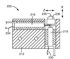
도 2는 마스터 롤을 제조하기 위한 다이아몬드 선삭 기계에 절삭 공구 및 이중 단축 액추에이터를 장착하도록 구성된 공구 장착 조립체의 일부분의 평면도.
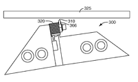
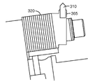
도 3a는 본 발명의 실시예에 따른, 다이아몬드 선삭 기계에 절삭 공구 및 단축 액추에이터를 장착하도록 구성된 공구 장착체의 일부분을 도시하는 도면.
도 3b는 도 3a에 도시된 단축 액추에이터 배열을 위한 X-Z 평면 내의 절삭 공구의 궤적을 도시하는 도면.
도 3c는 본 발명의 실시예에 따른, 마스터 롤의 표면에 실질적으로 수직하게 절삭 공구 팁의 각도를 유지하기 위해 사용되는, 액추에이터와 절삭 공구 사이에 장착된 스페이서를 도시하는 도면.
도 3d는 본 발명의 실시예에 따른, 마스터 롤의 표면에 실질적으로 수직하게 절삭 공구 팁의 각도를 유지하도록 절삭 공구를 장착하는 공구 섕크(shank)를 도시하는 도면.
도 3e는 본 발명의 실시예에 따른, 마스터 롤의 표면에 실질적으로 수직한 절삭 공구 팁을 제공하도록 래핑(lapping)된 절삭 공구를 도시하는 도면.
도 4는 본 발명의 실시예에 따른 모아레 방지, 웨트아웃 방지 프리즘 필름을 제작하기 위해 사용되는 마스터를 절삭하는 방법을 예시하는 흐름도.
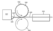
도 5는 본 발명의 실시예에 따른, 마스터 롤을 사용하여 모아레 방지 특징부 및 웨트아웃 방지 특징부를 갖는 프리즘 필름을 제작하는 시스템을 도시하는 도면.
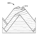
도 6a 및 도 6b는 본 발명의 실시예에 따른, 평면외 궤적을 따른 절삭에 의해 형성된 x축 및 z축 편위(excursion)를 갖는 마스터 롤을 사용하여 제작된 프리즘 필름을 각각 도시하는 사시도 및 단면도.
도 6c는 높이 변동 없이 피치 변동만을 갖는 프리즘 필름의 단면도.
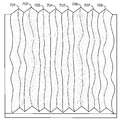
도 7a 및 도 7b는 본 발명의 실시예에 따른, 모아레 방지 특징부를 제공하도록 피치의 고주파수 변동을 갖는 프리즘들 - 몇몇 프리즘들은 웨트아웃 방지 특징부를 제공하도록 이웃 프리즘보다 더 큰 공칭 높이를 가짐 - 을 구비하는 프리즘 필름의 사시도 및 단면도.
도 8은 본 발명의 실시예에 따른, 웨트아웃 방지를 제공하도록 높이의 고주파수 변동을 갖는 프리즘들 - 프리즘들 사이에는 모아레 방지 특징부를 제공하도록 피치의 고주파수 변동을 갖는 프리즘들이 삽입 배치됨 - 을 구비한 프리즘 필름을 도시하는 도면.
도 9는 본 발명의 실시예에 따른, 프리즘 높이 및 피치의 고주파수 변동과 함께 프리즘의 공칭 피치의 점차적인 변동을 갖는 프리즘 필름을 도시하는 도면.
도 10은 본 발명의 실시예에 따른 웨트아웃 방지, 모아레 방지 표면을 갖는 필름을 사용하는 장치의 예를 도시하는 도면.
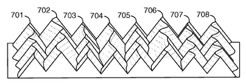
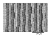
도 11a 및 도 11b는 본 발명의 실시예에 따른 궤적 절삭 방법에 의해 형성된 마스터를 사용하여 제작된 프리즘 피치 및 프리즘 깊이의 변동을 갖는 실질적으로 평행한 프리즘들을 구비한 프리즘 필름을 도시하는 주사 전자 현미경 사진.
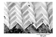
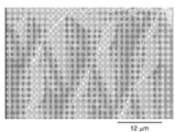
도 11c 및 도 11d는 본 발명의 실시예에 따른 궤적 절삭 방법에 의해 형성된 마스터를 사용하여 제작된 프리즘 피치 및 프리즘 깊이의 변동을 갖는 교차 프리즘들을 구비한 프리즘 필름을 도시하는 주사 전자 현미경 사진.BRIEF DESCRIPTION OF THE DRAWINGS Figure 1 is a diagram of a diamond turning machine system configured to produce a maste roll used to produce a prism film having a moire preventing feature and a wetout preventing feature in accordance with an embodiment of the present invention.
2 is a plan view of a portion of a tool mounting assembly configured to mount a cutting tool and a dual uniaxial actuator on a diamond turning machine for making a master roll;
Figure 3a illustrates a portion of a tool mount configured to mount a cutting tool and a uniaxial actuator in a diamond turning machine, in accordance with an embodiment of the present invention.
3B is a view showing the locus of the cutting tool in the XZ plane for the uniaxial actuator arrangement shown in Fig. 3A. Fig.
3C shows a spacer mounted between an actuator and a cutting tool, which is used to maintain the angle of the cutting tool tip substantially perpendicular to the surface of the master roll, in accordance with an embodiment of the present invention.
Figure 3d illustrates a tool shank for mounting a cutting tool to maintain the angle of the cutting tool tip substantially perpendicular to the surface of the master roll, in accordance with an embodiment of the present invention.
Figure 3e illustrates a cutting tool lapping to provide a cutting tool tip substantially perpendicular to the surface of the master roll, in accordance with an embodiment of the present invention.
4 is a flow chart illustrating a method of cutting a master used to produce a moiré anti-wetout, anti-wetout prism film according to an embodiment of the present invention.
5 illustrates a system for fabricating a prism film having a moire preventing feature and a wetout preventing feature using a master roll, according to an embodiment of the present invention.
6A and 6B are a perspective view and a cross-sectional view, respectively, of a prism film produced using a master roll having x-axis and z-axis excursion formed by cutting along an out-of-plane locus, according to an embodiment of the present invention .
6C is a sectional view of a prism film having only a pitch variation without a height variation.
FIGS. 7A and 7B are cross-sectional views of prisms having a high frequency variation of pitch to provide anti-moiré features, some prisms having a greater nominal height than a neighboring prism to provide a wetout prevention feature, according to an embodiment of the present invention; FIG. 6 is a perspective view and a cross-sectional view of a prism film provided; FIG.
Figure 8 is a perspective view of a prism having high frequency variations of height to provide wetout prevention, in accordance with an embodiment of the present invention; prisms with high frequency fluctuations of pitch are inserted and arranged to provide a moiré prevention feature between prisms; Fig.
9 illustrates a prism film having a prism height and a gradual variation of the nominal pitch of the prism with a high frequency variation of the pitch, according to an embodiment of the present invention.
10 is a view showing an example of an apparatus using a film having a wetout prevention, anti-moiré surface according to an embodiment of the present invention.
FIGS. 11A and 11B illustrate a scanning electron microscope (SEM) image showing a prism film having substantially parallel prisms having a variation of a prism pitch and a prism depth produced by using a master formed by a trajectory cutting method according to an embodiment of the present invention. Picture.
FIGS. 11C and 11D are scanning electron micrographs showing a prism film having cross prisms having a variation of a prism pitch and a prism depth manufactured using a master formed by a trajectory cutting method according to an embodiment of the present invention. FIG.
본 발명이 다양한 변형과 대안적 형태를 따르고 있지만, 그 특정예가 예로서 도면에 도시되고 상세히 설명될 것이다. 그러나, 본 발명이 설명된 특정 실시예로 한정되지 않는다는 것이 이해되어야 한다. 반대로, 첨부된 특허청구범위에 의해 한정되는 본 발명의 범주 내에 속하는 모든 변형예, 등가물 및 대안예를 포함하고자 하는 것이다.While the invention is amenable to various modifications and alternative forms, specific examples thereof are shown by way of example in the drawings and will be described in detail. It should be understood, however, that the invention is not limited to the specific embodiments described. On the contrary, the intention is to cover all modifications, equivalents, and alternatives falling within the scope of the invention as defined by the appended claims.
예시된 실시예들의 이하의 설명에서, 본 명세서의 일부를 형성하는 첨부 도면을 참조하며, 도면에서는 본 발명이 실시될 수 있는 다양한 실시예가 예시로서 도시되어 있다. 다른 실시예들이 이용될 수 있고, 구조적 또는 기능적 변화가 본 발명의 범주로부터 벗어나지 않고서 이루어질 수 있음이 이해될 것이다.In the following description of the illustrated embodiments, reference is made to the accompanying drawings which form a part hereof, and in which is shown by way of illustration various embodiments in which the invention may be practiced. It is to be understood that other embodiments may be utilized and structural or functional changes may be made without departing from the scope of the present invention.
디스플레이를 위한 필름의 사용은 잘 알려져 있다. 예를 들어, 백라이트 디스플레이에서, 휘도 향상 필름은 프리즘형 구조물을 사용하여 시야축(viewing axis)을 따라 광을 지향시켜서, 보는 사람에 의해 인지되는 광의 휘도를 향상시킨다. 다른 예로서, 백라이트 컴퓨터 디스플레이 스크린은, 소정의 선택된 방향으로는 높고 균일한 휘도를 그리고 다른 방향으로는 더 낮은 휘도를 동시에 유지하면서 높은 콘트라스트 및 높은 전체 휘도를 갖는 스크린을 생성하기 위해 다수의 상이한 필름들을 사용할 수 있다. 그러한 스크린은 프리즘형 필름 또는 렌티큘러 필름(lenticular film)과 조합한 확산 필름을 비롯한 몇몇 유형의 필름을 사용할 수 있다.The use of films for display is well known. For example, in a backlit display, a brightness enhancement film uses a prismatic structure to direct light along a viewing axis, thereby enhancing the brightness of light perceived by the viewer. As another example, a backlit computer display screen may include a plurality of different films to produce a screen with high contrast and high overall brightness while simultaneously maintaining high and uniform brightness in a given selected direction and lower brightness in the other direction Can be used. Such a screen may use some type of film, including a prismatic film or a diffusion film in combination with a lenticular film.
디스플레이에서 필름을 사용하는 것과 관련한 하나의 문제점은 컴퓨터 디스플레이와 같이 근접 뷰잉(viewing)용으로 의도된 디스플레이에 대한 표면적인 요건이 매우 높다는 것이다. 이는 그러한 디스플레이가 장기간 동안 근접하여 보여지기 때문이고, 그래서 심지어 매우 작은 결함도 발견되어 보는 사람에게 거슬림을 야기할 수 있다. 그러한 결함의 제거는 검사 시간과 재료 둘 모두에서 비용이 많이 들 수 있다.One problem with using films in displays is that the surface requirements for displays intended for close viewing, such as computer displays, are very high. This is because such a display is visible for a long period of time, and even very small defects can be found causing irritation to the viewer. Elimination of such defects can be costly at both the inspection time and the material.
결함은 몇몇 상이한 방식으로 나타난다. 반점, 린트(lint), 스크래치, 함유물 등과 같은 물리적 결함과, 또한 광학 현상인 결함이 있다. 그 중에서 가장 일반적인 광학 현상은 "웨트-아웃" 및 뉴턴 링(Newton's rings)이다. "웨트-아웃"은 2개의 표면이 서로 광학적으로 접촉할 때 발생하여서, 하나의 표면으로부터 다음 표면으로 전파되는 광의 굴절률 변화를 효과적으로 제거한다. 이는 광학 효과를 위해 구조화된 표면을 사용하는 필름의 경우 특히 문제가 되는데, 그 이유는 구조화된 표면의 굴절 특성이 무효로 되기 때문이다. "웨트-아웃"의 효과는 스크린에 얼룩덜룩하고 변하는 외양을 생성하는 것이다. 뉴턴 링은 2개의 필름들 사이의 먼지 입자에 의해 생성될 수 있는 바와 같이, 2개의 필름들 사이에서의 천천히 변하는 공기 간극의 결과이다. 뉴턴 링은 투과 또는 반사에서 형성될 수 있다. 뉴턴 링의 결과는 거슬릴 수 있는 스크린 상의 윤곽 패턴을 보는 사람이 인지한다는 것이다. 모아레 효과는 실질적으로 동일한 피치의 선형 프리즘들을 갖는 둘 이상의 필름들이 덧씌워졌을 때 나타날 수 있는 광학적 간섭 패턴에 의해 야기된다. 전술된 결함은 보는 사람에게 바람직하지 않고 거슬리는 불균일하거나 얼룩덜룩하거나 고르지 않은 모습을 디스플레이에 부여한다.Defects appear in several different ways. Physical defects such as spots, lint, scratches, inclusions and the like, as well as optical defects. The most common optical phenomena are "wet-out" and Newton's rings. "Wet-out" occurs when two surfaces are in optical contact with each other, effectively eliminating the refractive index change of light propagating from one surface to the next. This is particularly problematic in the case of films using structured surfaces for optical effects, because the refracting properties of the structured surface are rendered ineffective. The effect of "wet-out" is to create a mottled and changing appearance on the screen. Newton rings are the result of slowly varying air gaps between the two films, as can be created by the dust particles between the two films. Newton rings can be formed in transmission or reflection. The result of Newton 's ring is that the viewer sees a contour pattern on the screen that can be offensive. The moire effect is caused by an optical interference pattern that can appear when two or more films having linear prisms of substantially the same pitch are superimposed. The above-mentioned defects give the display an unfavorable, irregular, mottled or uneven appearance that is undesirable to the viewer.
다중-필름 디스플레이 조립체에서의 결함의 문제를 극복하기 위해 몇몇 접근법이 추구되었다. 하나는 종래의 제조 방법에 의해 생산되는 수용가능한 디스플레이 조립체의 낮은 수율을 단순히 수용하는 것이다. 이는 경쟁 시장에서 명백히 수용불가능하다. 제2 접근법은 매우 청정하고 면밀한 제조 절차를 채택하고, 엄격한 품질 제어 표준을 부과하는 것이다. 이는 수율을 개선할 수 있지만, 청정 설비 및 검사의 비용을 감당하기 위해 생산 비용이 증가된다.Several approaches have been sought to overcome the problem of defects in multi-film display assemblies. One is simply accepting a low yield of an acceptable display assembly produced by conventional manufacturing methods. This is clearly unacceptable in competitive markets. The second approach is to adopt very clean and careful manufacturing procedures and impose strict quality control standards. This can improve the yield, but the cost of production increases to cover the cost of clean installations and inspection.
결함을 감소시키는 다른 접근법은 표면 확산기 또는 벌크 확산기인 확산기를 디스플레이에 도입하는 것이다. 그러한 확산기는 많은 결함을 감출 수 있고, 낮은 추가 비용으로 제조 수율을 증가시킬 수 있다. 그러나, 확산기는 광을 산란시키고 보는 사람에 의해 인지되는 광의 축상(on-axis) 휘도를 감소시켜서, 성능을 저하시킨다. 거의 추가 비용을 들이지 않고서 제조 수율을 개선함과 동시에 성능을 유지하도록, 디스플레이에서의 결함의 발생을 감소시킬 필요성이 지속되고 있다.Another approach to reducing defects is to introduce a diffuser, which is a surface diffuser or bulk diffuser, into the display. Such diffusers can mask many defects and increase manufacturing yield at low additional cost. However, diffusers scatter light and reduce the on-axis luminance of light perceived by the viewer, thereby degrading performance. There is a continuing need to reduce the incidence of defects in the display to improve performance while at the same time improving manufacturing yields with little additional expense.
본 발명의 실시예는 필름을 포함하는 디스플레이에서 눈에 띄는 결함의 발생을 감소시키는 프리즘 필름과, 그러한 필름을 제조하는 방법 및 시스템에 관한 것이다. 본 명세서에 기술된 접근법에 따라 형성된 프리즘 필름은 프리즘의 높이 및 피치를 변화시킴으로써 모아레 방지 특징부 및 웨트아웃 방지 특징부 둘 모두를 제공한다. 프리즘 피치의 변동은 모아레 간섭 패턴의 출현을 감소시킨다. 프리즘 높이의 변동은 웨트아웃 영역의 발생을 감소시킨다.Embodiments of the present invention are directed to a prism film that reduces the occurrence of visible defects in a display comprising a film, and to a method and system for making such films. The prism film formed in accordance with the approach described herein provides both the anti-moiré feature and the wetout prevention feature by varying the height and pitch of the prism. The variation of the prism pitch reduces the appearance of the moiré interference pattern. The variation of the height of the prism reduces the occurrence of the wetout region.
본 명세서에 기술된 프리즘 필름은 액정 디스플레이에서 특히 유용하고, 오버헤드 및 후방 프로젝션 스크린을 비롯한 다양한 유형의 프로젝션 스크린에서 또한 유용하다. 본 명세서에 기술된 형태에 따른 모아레 방지 특징부 및 웨트아웃 방지 특징부를 갖는 프리즘 필름은 많은 예기치 않은 그리고 유리한 결과를 생성한다. 예를 들어, 최대 편위로 나타나는 웨트아웃 방지 특징부들은 유리하게는 서로에 대해 등거리에 배치되어, 필름에 보다 균일한 지지를 제공할 수 있다. 프리즘 피치의 변동은 쑥 들어간 피크에서 유지되기 때문에, 결함 및 모아레 콘트라스트를 감소시키는 능력이 유지된다.The prism films described herein are particularly useful in liquid crystal displays and are also useful in various types of projection screens, including overhead and rear projection screens. The prismatic film with anti-Moire features and wet-out prevention features in accordance with aspects described herein produces many unexpected and beneficial results. For example, the wet-out protection features that appear up to the maximum can advantageously be equidistant relative to one another to provide a more uniform support to the film. Since the variation of the prism pitch is maintained at the wobbling peak, the ability to reduce defects and moire contrast is maintained.
몇몇 실시예에서, 명목상으로 평면내(in plane)였던 표면 상에서 프리즘 마스터에 피크 및 깊이의 변동을 동시에 형성하기 위해 단축 평면외 운동이 사용된다. 이들 특징부를 갖는 이 마스터로부터 제작된 필름은 웨트아웃 방지 성능에서 인상적인 결과를 가져온다.In some embodiments, a uniaxial out-of-plane motion is used to simultaneously create variations in peak and depth on the prism master on a surface that was nominally in-plane. Films made from this master with these features give impressive results in wetout prevention performance.
프리즘 필름을 제조하기 위해 사용되는 마스터는 음각(negative relief)으로 마스터의 표면 내로 절삭된 프리즘 특징부를 갖는다. 마스터의 제작 후에, 마스터는 예를 들어 엠보싱, 압출, 캐스팅 및 경화, 및/또는 다른 공정에 의해 프리즘 필름을 제조하기 위해 사용될 수 있다.The master used to make the prism film has prism features cut into the surface of the master with negative relief. After fabrication of the master, the master may be used to produce the prism film by, for example, embossing, extrusion, casting and curing, and / or other processes.
프리즘 필름 마스터는 전형적으로 원하는 프리즘 형상의 네거티브(negative)인 홈을 갖는 원통형 롤이다. 홈은 다이아몬드 선삭에 의해 마스터 내로 절삭될 수 있다. 마스터의 표면은 전형적으로 경질 구리의 것이지만, 알루미늄, 니켈, 강철 또는 플라스틱(예를 들어, 아크릴)과 같은 다른 재료가 또한 사용될 수 있다. 다수의 동심 홈이 마스터 롤의 원주 둘레에 절삭될 수 있다. 마스터 롤은 회전하는 마스터 롤의 표면에 평행한 방향으로 다이아몬드 공구가 이동되는 동안에 단일의 연속적인 절삭부가 롤에 만들어지는 나사 절삭(thread cutting), 또는 복수의 동심 홈이 개별적으로 공작물에 형성되는 플런지 절삭(plunge cutting)으로서 알려진 기술에 의해 기계가공될 수 있다.The prism film master is typically a cylindrically shaped roll with a negative groove of the desired prism shape. The grooves can be cut into the master by diamond turning. The surface of the master is typically of a hard copper, but other materials such as aluminum, nickel, steel or plastic (e.g., acrylic) may also be used. A plurality of concentric grooves can be cut around the circumference of the master roll. The master roll is thread cutting, in which a single continuous cutting portion is made on the roll while the diamond tool is moved in a direction parallel to the surface of the rotating master roll, or a plurality of concentric grooves are formed on the workpiece Can be machined by techniques known as plunge cutting.
다이아몬드 선삭 기계는 전형적으로 마스터에 홈을 절삭하기 위해 사용되는 절삭 공구의 이동을 제어하는 제어기를 포함한다. 다이아몬드 선삭 기계는 절삭 공구가 마스터 내로 침투하는 깊이와, 마스터의 표면을 따른 공구의 측방향 운동을 독립적으로 제어할 수 있다. 부가적으로, 다이아몬드 선삭 기계는 원통형 마스터의 회전 속도를 독립적으로 제어할 수 있다.Diamond turning machines typically include a controller that controls the movement of the cutting tool used to cut grooves in the master. The diamond turning machine can independently control the depth at which the cutting tool penetrates into the master and the lateral movement of the tool along the surface of the master. In addition, the diamond turning machine can independently control the rotational speed of the cylindrical master.
프리즘 필름을 제조하기 위해 사용되는 마스터 롤을 제조하도록 구성된 다이아몬드 선삭 시스템이 도 1에 도시되어 있다. 원통형 마스터(100)가 드럼 구동기(104)에 의해 축(102)을 중심으로 회전된다. 이 예에서 마스터(100)가 원통형 형태로 도시되었지만, 대안적인 형태에서 마스터는 평면형일 수 있다. 동심 홈을 플런지 절삭함으로써, 또는 얕은 홈(110)을 마스터(100) 상에 나사 절삭함으로써, 즉 마스터(100)의 표면 내로 절삭하는 동안 절삭 공구(108)를 z-방향으로 병진시킴으로써 웨트아웃 방지, 모아레 방지 표면 패턴이 마스터(100) 내로 절삭될 수 있다. 마스터(100)의 표면은 필름의 상호보완적인 표면을 형성하기 때문에, 마스터 표면 상의 국부적 최소점은 필름이 제작되었을 때 필름 표면 상의 국부적 최대점에 대응한다.A diamond turning system configured to produce a master roll used for manufacturing a prism film is shown in Fig. The
전형적으로, 제어기(106)는 절삭 공구 장착체(109)를 z-방향으로 측방향 구동하여 절삭 공구(108)를 회전 마스터(100)를 따라 이동시켜 연속적인 나사형 절삭부 또는 불연속적인 동심 절삭부를 만든다. 제어기(106)는 드럼 구동기(104)의 속도를 제어하고 마스터(100)의 각 위치(angular position, Ψ)를 모니터링할 수 있다.The
제어기(106)는 마스터 표면에 평행한 z-방향으로의 절삭 공구의 저주파수 편위를 일으키도록 그리고 마스터의 표면에 수직인 x-방향으로의 절삭 공구의 저주파수 편위를 일으키도록 절삭 공구 장착체(109)의 이동을 제어한다. 제어기(106)는 또한 절삭 공구의 고주파수 편위를 발생시키도록 하나 이상의 고속 서보 액추에이터(fast servo actuator, 138)를 통해 절삭 공구(108)의 이동을 제어할 수 있다. 절삭 공구(108)와 마스터 표면(100) 사이의 각도(θ)가 또한 제어될 수 있다. 절삭 공구(108)의 크기 및 형상은 마스터(100)가 사용되어 제조할 필름의 특정 유형에 따라 선택된다.The
하나 이상의 액추에이터(138)의 이동은 절삭 공구(108)의 짧고 빠른 편위를 발생시키기 위해 사용되는 반면에, 절삭 공구 장착체(109)의 운동은 절삭 공구(108)의 보다 길고 보다 느린 편위를 발생시키기 위해 사용된다. 장착체의 저주파수 운동은 고속 서보 액추에이터(138)의 스트로크(stroke) 길이보다 큰 양만큼 마스터(100)에서의 표면 절삭부를 변화시키기 위해 사용될 수 있다. 제어기(106)는 절삭 공구(108)의 고주파수 이동 및 저주파수 이동을 제어하는 제어 신호를 생성한다. 제어 신호는 절삭 공구 장착체(109)에 관한 저주파수 성분 및 액추에이터(138)에 관한 고주파수 성분을 포함할 수 있다.Movement of the one or
제어 신호의 고주파수 성분 및/또는 저주파수 성분은 마스터(100)의 회전에 동기식일 수 있고, 주기적, 랜덤, 비-랜덤 또는 의사 랜덤일 수 있다. 예를 들어, 하나 이상의 액추에이터(138)의 이동은, 절삭 공구(108)의 보다 크고 보다 느린 이동을 만들도록 제어되는 장착체(109)의 이동 동안에, 절삭 공구(108)의 작고 빠른 이동을 만들도록 제어될 수 있다. 이와 같이, 액추에이터(138)에 의해 발생된 절삭 공구(108)의 보다 높은 주파수 이동은 장착체(109)에 의해 발생된 절삭 공구(108)의 보다 낮은 주파수 운동에 부가된다. 장착체(109) 및/또는 액추에이터(138)의 이동은 랜덤, 의사 랜덤 또는 비-랜덤일 수 있다. 의사 랜덤 이동은 컴퓨터-생성 랜덤성(computer generated randomness)에 의해 달성될 수 있다. 각각의 롤 공구에 대해 동일한 랜덤 신호를 반복하여, 롤 공구들이 동일한 기록된 랜덤성을 포함하고 결과적인 구조가 롤들 사이에 동일한 것이 바람직할 수 있다. 몇몇 실시예에서, 액추에이터(138) 및/또는 공구 장착체(109)의 이동은 주기적 패턴 또는 사인파 패턴과 같이 대체로 비-랜덤일 수 있는데, 이는 홈(110)의 피치 또는 깊이 패턴의 위상 시프트(phase shift)를 야기하는 산발적인 랜덤 이동에 의해 랜덤화된다.The high frequency and / or low frequency components of the control signal can be synchronous to the rotation of the
하나 이상의 액추에이터(138)가 절삭 공구 장착체(109)의 이동에 의해서는 통상적으로 얻을 수 없는 고주파수로 절삭 공구(108)를 이동시키도록 작동한다. 각각의 액추에이터(138)는 압전 변환기(piezoelectric transducer, PZT), 또는 제어기(106)로부터의 전기 신호를 궁극적으로 절삭 공구(108)의 운동을 제어하는 액추에이터(138)의 이동으로 변환시키는 다른 변환기와 같은 변환기를 갖는 단축 고속 공구 서보(fast tool servo)를 포함한다. 고속 서보 액추에이터의 응답의 주파수 상한은 수 ㎑ 내지 수십 ㎑의 범위에 있을 수 있는 반면에, 절삭 공구 장착체의 주파수 응답은 전형적으로 5 ㎐ 이하이다. 예를 들어, 공구 장착체(109)의 이동은 약 500,000 마이크로미터의 거리(파장)에 걸쳐 약 0.5 마이크로미터 내지 약 50 마이크로미터의 홈 피치의 저주파수 변동을 달성할 수 있다. 공구 장착체(109)의 이동은 약 2,000,000 마이크로미터의 파장을 가지고서 약 0.5 마이크로미터 내지 약 50 마이크로미터의 홈 깊이의 저주파수 변동을 달성할 수 있다.One or
액추에이터(138)가 발생시키는 스트로크의 길이는, 예를 들어 약 5 마이크로미터 내지 약 500 마이크로미터의 파장을 가지고서 50 마이크로미터 미만, 또는 약 0.5 마이크로미터 내지 약 50 마이크로미터의 범위일 수 있다. 이러한 더 높은 주파수 변동의 범위는 향상된 결함-은폐 및 광 산란을 제공하기 위해 사용될 수 있다. 넓은 시야각이 바람직한 실시예에서, 보다 세밀한 피치는 예를 들어 디스플레이의 컷오프 각도(cutoff angle)를 부드럽게 하고 매끄럽게 한다. 스트로크의 길이와 상위 주파수 응답 사이에 절충(trade-off)이 있을 수 있음이 이해될 것이다.The length of the stroke generated by the
마스터(100)의 표면 상에 절삭된 결과적인 홈(110)은 절삭 공구(108)에 대한 롤의 표면 속도에 좌우되는 롤 원주 둘레의 국부적 x 및/또는 z 편위들 사이의 평균 간격, 및 절삭 공구(108)의 편위들 사이의 평균 기간을 갖는다. 예를 들어, 직경이 30.48 ㎝ (12 인치)인 드럼은 200 rpm으로 회전될 수 있는 반면에, 액추에이터(138)는 공구를 약 20 ㎑로 사인파식으로 구동한다. 결과적인 파장은 액추에이션 벡터(actuation vector)의 평면에서 160 마이크로미터일 것이다.The resulting
도 2는 절삭 공구(236) 및 액추에이터(218, 216)를 다이아몬드 선삭 기계에 장착하기 위해 사용되는 공구 장착 조립체(200)의 일부분의 평면도를 제공한다. 공구 장착 조립체(200)는 단축 x-방향 액추에이터(218), 단축 z-방향 액추에이터(216) 및 절삭 공구(236)를 유지할 수 있는 본체(212)를 포함한다. 이 예에서, 액추에이터(216, 218)는 PZT 스택(stack)이다. PZT 스택(218, 216)은 절삭 공구(236)를 x-방향 및 z-방향으로 각각 이동시키도록 배열된다. PZT 스택(218, 216)은 절삭 공구(236)의 정밀 제어 이동을 위해 필요한 안정성을 위하여 공구 장착 조립체(200)에 단단히 장착된다. PZT 스택(218, 216)은 제어기로부터 신호를 수신하는 전기 접속부(230, 234)를 포함한다.Figure 2 provides a top view of a portion of the
절삭 공구 팁(235)은 마스터 롤의 표면에 수직하게 배향될 수 있다. 마스터가 회전할 때 x-축 액추에이터(218)의 제어 하에서의 절삭 공구의 이동은 가변 깊이의 평행 홈들이 마스터 내로 절삭되게 한다. 마스터 롤이 회전할 때 z-방향 액추에이터(216)의 제어 하에서의 절삭 공구의 이동은 가변 피치의 홈들이 마스터 롤 내로 절삭되게 한다. 몇몇 형태에서, 홈들은 실질적으로 선형이고 적어도 얼마간의 거리에 걸쳐 실질적으로 평행할 수 있다. 몇몇 실시예에서, 홈은 교차할 수 있다.The
프리즘 필름을 제조하는 데에 사용하기 위한 독립적인 x 및 z 이동을 갖는 절삭 공구 조립체가 본 명세서에 참고로 포함된 공동 소유의 미국 특허 공개 제2007/0107568호에 기술되어 있다.Cutting tool assemblies with independent x and z movements for use in manufacturing prism films are described in co-owned US Patent Application Publication No. 2007/0107568, which is incorporated herein by reference.
본 발명의 실시예는 절삭 공구의 이동을 제어하기 위해 단 하나의 단축 액추에이터만을 사용하는 프리즘 필름 마스터를 제조하는 시스템 및 방법에 관한 것이다. 단축 액추에이터의 사용은 상호 종속적인 x 및 z 성분을 갖는 홈을 절삭하기 위해 이용될 수 있다.Embodiments of the present invention are directed to a system and method for manufacturing a prism film master using only a single actuator to control movement of a cutting tool. The use of a uniaxial actuator can be used to cut grooves with interdependent x and z components.
절삭 공구는, 단축 액추에이터의 작동이 절삭 공구가 x 성분과 z 성분 둘 모두를 갖는 궤적을 따라 이동하게 하여 마스터의 표면과는 평면외인 절삭 공구 운동을 발생시키도록, 마스터에 대해 배향된다. 절삭 공구의 평면외 이동은 홈 깊이와 홈 피치 둘 모두에서 변동을 갖는 홈을 마스터 롤에 절삭한다. 프리즘 필름이 마스터 롤을 사용하여 제조될 때, 마스터의 가변 피치, 가변 깊이 홈은 가변 피치, 가변 높이 프리즘으로 된다. 앞서 논의된 바와 같이, 가변 피치, 가변 높이 프리즘은 프리즘 필름에서 모아레 방지 특징부 및 웨트아웃 방지 특징부를 제공한다.The cutting tool is oriented with respect to the master so that the action of the uniaxial actuator causes the cutting tool to move along a locus having both the x and z components and to produce a cutting tool motion that is out of plane with the master's surface. Out-of-plane movement of the cutting tool cuts grooves having variations in both groove depth and groove pitch into the master roll. When the prism film is manufactured using the master roll, the variable pitch and variable depth grooves of the master are variable pitch and variable height prisms. As discussed above, variable pitch, variable height prisms provide moiré prevention features and wetout prevention features in the prism film.
하나의 단축 액추에이터의 작동은 깊이 변동 및 피치 변동 둘 모두를 갖는 홈을 절삭하는 절삭 공구의 선형 운동을 발생시킬 수 있다. 단축 액추에이터의 사용은 필요한 구성요소들의 개수를 감소시키고, 공구 장착체의 구성을 간단하게 하며, 제어기 전자기기를 간단하게 하고, 구조화된 필름이 생성될 수 있는 속도를 증가시키며, 모아레 방지 프리즘 특징부 및 웨트아웃 방지 프리즘 특징부 둘 모두를 갖는 마스터 공구를 제작한다. 단축 액추에이터를 사용하여 달성할 수 있는 피치의 변동은 약 5 내지 약 500 마이크로미터의 파장을 가지고서 약 0.5 내지 약 50 마이크로미터의 피치의 변동이다. 단축 액추에이터를 사용하여 달성할 수 있는 깊이의 변동은 약 5 내지 약 500 마이크로미터의 파장을 가지고서 약 0.5 내지 약 50 마이크로미터 깊이의 변동이다.Operation of one single actuator may result in a linear motion of the cutting tool that cuts the groove with both depth variation and pitch variation. The use of a single actuator reduces the number of required components, simplifies the construction of the tool mount, simplifies the controller electronics, increases the speed at which a structured film can be produced, And a wet-out preventing prism feature. The variation in pitch that can be achieved using a single actuator is a variation of the pitch of about 0.5 to about 50 micrometers with a wavelength of about 5 to about 500 micrometers. Variations in depth that can be achieved using a single actuator are variations of about 0.5 to about 50 micrometers in depth with a wavelength of about 5 to about 500 micrometers.
도 3a는 절삭 공구(310) 및 단축 액추에이터(320)를 다이아몬드 선삭 기계에 장착하도록 구성된 공구 장착체(300)의 일부분을 도시한다. 절삭 공구(310) 및 액추에이터(320)는 액추에이터(320)(예를 들어, PZT 액추에이터)의 작동이 절삭 공구(310)의 축외(off-axis) 운동을 발생시키도록 배향된다. PZT 액추에이터(320)의 작동은 x 성분과 z 성분 둘 모두를 갖고 마스터(325)의 표면과는 축외인 궤적을 따라 절삭 공구(310)를 이동시킨다.3a shows a portion of a
도 3b는 도 3a에 도시된 바와 같은 단축 액추에이터 배열을 위한 X-Z 평면 내의 절삭 공구(310)의 궤적(350)을 도시한다. 절삭 공구(310)는 궤적(350)을 따라 전후로 이동하여 마스터에 가변 깊이 및 가변 피치 홈을 절삭한다. 궤적(350)은 요구되는 x 성분 및 z 성분의 양에 따라 단축 액추에이터를 위해 조정될 수 있다. 최대 사변(hypotenuse) 길이는 단축 액추에이터 이동 능력에 의해 결정된다.Figure 3B shows the
예를 들어, 20 마이크로미터의 이동이 가능한 PZT 스택의 경우, 3 마이크로미터의 웨트아웃 방지 변동(x-축 성분)이 요구되도록 액추에이터가 회전될 수 있다. x축 성분이 3 마이크로미터이고, 사변이 20 마이크로미터이면, 액추에이터는 마스터 표면에 대해 8.6도의 각도(Γ)로 배향된다. 피타고라스의 정리를 사용하여, z-축을 따른 모아레 방지 성분이 19.7 마이크로미터인 것으로 계산된다.For example, for a 20 micrometer mobile PZT stack, the actuator may be rotated such that a wetout prevention variation (x-axis component) of 3 micrometers is required. If the x-axis component is 3 micrometers and the oblique angle is 20 micrometers, the actuator is oriented at an angle (Γ) of 8.6 degrees with respect to the master surface. Using the Pythagorean theorem, the anti-moiré component along the z-axis is calculated to be 19.7 micrometers.
절삭 공구(310)의 팁은 마스터의 표면에 수직하게 배향될 수 있거나, 또는 마스터 표면에 대해 소정 각도로 배향될 수 있다. 공구 팁 배향은 많은 방식으로 달성될 수 있다. 도 3c에 도시된 바와 같이, 배향 스페이서(370)가 PZT 액추에이터(320)와 공구 섕크(360) 사이에 채용될 수 있다. 도 3d에 도시된 바와 같이, 공구 섕크(365)가 원하는 기하학적 형태를 직접 포함할 수 있다. 공구(310)는 도 3a에 도시된 바와 같이 섕크(366) 상에서 원하는 각도로 배향될 수 있다. 공구 팁(305)은 도 3e에 도시된 바와 같이 원하는 배향을 포함하도록 래핑되거나 형성될 수 있다.The tip of the
도 4는 본 발명의 실시예에 따른 모아레 방지, 웨트아웃 방지 프리즘 필름을 제작하기 위해 사용되는 마스터를 절삭하는 방법을 예시하는 흐름도이다. 절삭 공구를 마스터의 표면에 대해 이동시켜 표면에 홈을 절삭한다(단계 410). 표면에 대한 절삭 공구의 이동은 마스터의 표면에서의 홈의 나사 절삭 또는 동심 홈의 절삭을 발생시킬 수 있다. 절삭 공구가 표면에 대해 이동될 때, 절삭 공구는 또한 0이 아닌 x 및 z 성분을 갖고 표면과는 평면외인 궤적을 따라 전후로 단축 고속 서보 액추에이터를 통해 이동된다(단계 420). 궤적을 따른 절삭 공구의 이동은 표면에 절삭된 홈이 가변 피치와 가변 깊이 둘 모두를 갖게 한다.4 is a flow chart illustrating a method of cutting a master used to produce a moire preventing, wet-out preventing prism film according to an embodiment of the present invention. The cutting tool is moved relative to the surface of the master to cut grooves on the surface (step 410). Movement of the cutting tool relative to the surface can result in thread cutting of the grooves at the surface of the master or cutting of the concentric grooves. When the cutting tool is moved relative to the surface, the cutting tool is also moved (step 420) through the shortened high-speed servo actuator back and forth along a locus that has non-zero x and z components and is out of plane with the surface. The movement of the cutting tool along the trajectory causes the cut grooves on the surface to have both a variable pitch and a variable depth.
모아레 방지 특징부 및 웨트아웃 방지 특징부를 갖는 프리즘 필름은 도 5에 도시된 바와 같이 특정 치수만큼 이격된 한 쌍의 롤러들 사이에서 캐스팅함으로써 형성될 수 있다. 도 5에서, 필름(502)이 다이(die, 500)를 통해 저장조(501)로부터 당겨진다. 필름(502)은 원하는 프리즘 구조물의 네거티브인 홈(507)을 지닌 마스터 롤(506)과 닙 롤(nip roll, 504) 사이에 니핑(nipping)된다. 마스터 롤(506)은 필름(502)의 상부 표면 상에 프리즘 패턴(508)을 형성한다. 롤러(504, 506)들 사이를 통과한 후에, 필름(502)은 예를 들어 냉각기(520)에서 냉각되고, 롤러(504, 506)들에 의해 필름 상에 엠보싱된 패턴을 유지한다.The prism film having the anti-Moire feature and the wet-out preventing feature can be formed by casting between a pair of rollers spaced apart by a specific dimension as shown in Fig. In Figure 5, the
하나의 프리즘 필름 실시예에서, 마스터 롤(506)은 0이 아닌 x 성분 및 z 성분을 갖고 마스터 롤의 표면과는 평면외인 궤적을 따른 절삭 공구의 고주파수 편위에 의해 절삭된 홈(507)을 지닌다. 마스터 롤(506)에 의해 형성된 프리즘은 모아레 방지 특징부를 제공하는 피치의 랜덤, 의사 랜덤 또는 비-랜덤 변동을 가질 수 있고/있거나 웨트아웃 방지 특징부를 제공하도록 높이의 대응하는 랜덤, 의사 랜덤 또는 비-랜덤 변동을 가질 수 있다. 예를 들어, 프리즘 높이 및 피치의 변동은 약 500 마이크로미터의 파장을 가지고서 약 0.5 마이크로미터 내지 약 50 마이크로미터의 범위를 가질 수 있다.In one prism film embodiment, the
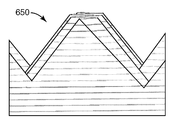
도 6a는 평면외 궤적을 따른 절삭에 의해 형성된 x축 및 z축 편위를 갖는 마스터 롤을 사용하여 형성된 프리즘 필름(600)을 도시한다. 도 6a 내지 도 6c의 프리즘 필름에 그려진 선들은 프리즘의 높이 변동을 보다 명확하게 도시하고자 하는 것이다. 프리즘 필름(600)은 프리즘 피치(p)의 모아레 방지 변동 및 프리즘 높이(h)의 웨트아웃 방지 변동 둘 모두를 갖는 프리즘(610)을 포함한다. 도 6b는 프리즘 높이 및 피치의 변동을 도시하는 도 6a의 프리즘 필름(600)의 프리즘 피크(610)의 단면도이다. 비교를 위해, 도 6c는 높이 변동 없이 피치 변동만을 갖는 프리즘을 구비한 프리즘 필름(650)의 단면도이다.6A shows a
다른 프리즘 필름 실시예에서, 마스터 롤은 절삭 공구의 저주파수 x축 운동과 결합된 하나의 단축 고속 서보 액추에이터에 의해 제어되는 절삭 공구의 고주파수 운동에 의해 절삭된 홈을 지닌다. 단축 액추에이터는 도 3a에 도시된 바와 같이 평면외 x 및 z 운동을 제공하는 단축 액추에이터 또는 z축 액추에이터일 수 있다. 프리즘 필름은 모아레 방지 특징부를 제공하도록 피치의 고주파수 변동을 갖는 프리즘을 포함하는데, 여기서 프리즘들 중 일부는 웨트아웃 방지 특징부를 제공하도록 이웃 프리즘보다 더 큰 공칭 높이를 갖는다. 이러한 유형의 프리즘 필름의 일례가 도 7a 및 도 7b의 평면도 및 단면도에 의해 각각 도시된다. 도 7a에서, 프리즘(701 내지 708)은 프리즘 피치의 변동을 나타낸다. 프리즘(702, 706)의 공칭 높이는 프리즘(701, 703 내지 705, 707, 708)의 공칭 높이보다 크다. 도 7a 및 도 7b의 프리즘 필름에 그려진 선들은 프리즘의 높이 변동을 보다 명확하게 도시하고자 하는 것이다.In another prism film embodiment, the master roll has grooves cut by high frequency motion of the cutting tool controlled by one single-axis high-speed servo actuator combined with low frequency x-axis motion of the cutting tool. The uniaxial actuator may be a uniaxial actuator or a z-axis actuator that provides out-of-plane x and z motion as shown in FIG. 3A. The prismatic film includes a prism having a high frequency variation of the pitch to provide a moiré feature, wherein some of the prisms have a greater nominal height than the neighboring prism to provide a wetout prevention feature. An example of this type of prism film is shown by a plan view and a cross-sectional view, respectively, of Figs. 7a and 7b. In Fig. 7A,
또 다른 프리즘 필름 실시예에서, 마스터 롤은 z축 액추에이터에 의해 제어되는 절삭 공구의 고주파수 z축 운동에 의해 절삭된 제1 세트의 홈들을 지닌다. 제1 세트의 홈들 사이에, x축 액추에이터에 의해 제어되는 절삭 공구의 고주파수 운동에 의해 절삭된 제2 세트의 홈들이 삽입 배치된다. 예를 들어, 마스터 롤은 x축 변동을 갖는 n개의 홈이 사이에 삽입 배치된, z축 변동을 갖는 m개의 홈을 가질 수 있다. 도 8은 그러한 마스터 롤을 사용하여 형성된 프리즘 필름을 도시하는데, 여기서 m 및 n은 1이다. 프리즘(801, 803, 805, 807)들은 웨트아웃 방지를 제공하도록 높이의 고주파수 변동을 갖는다. 웨트아웃 방지 프리즘(801, 803, 805, 807)들 사이에, 모아레 방지 특징부를 제공하는, 피치의 고주파수 변동을 갖는 프리즘(802, 804, 806, 808)들이 삽입 배치된다.In another prism film embodiment, the master roll has a first set of grooves cut by the high frequency z-axis movement of the cutting tool controlled by the z-axis actuator. Between the first set of grooves, a second set of grooves cut by the high-frequency motion of the cutting tool controlled by the x-axis actuator are inserted and disposed. For example, the master roll may have m grooves with z-axis variations in which n grooves with x-axis variations are interleaved between them. Figure 8 shows a prism film formed using such a master roll, where m and n are one. The
추가의 프리즘 필름 실시예에서, 마스터 롤 내로 절삭된 홈은 마스터 롤 표면과는 평면외인 궤적을 따른 절삭 공구 이동을 제공하는 단축 액추에이터에 의해 형성된 고주파수 피치 및 깊이 변동에 부가된 저주파수 프리즘-대-프리즘 피치 변동을 포함한다. 도 9는 이러한 유형의 마스터 롤을 사용하여 형성된 프리즘 필름(900)을 도시한다. 프리즘(910)의 공칭 피치는, 일부 프리즘들 사이의 피치(P1)가 다른 프리즘들 사이의 피치(P2)보다 작도록, 프리즘 간에 점차 변화한다. 각각의 프리즘(910)은 또한 위에서 논의된 바와 같이 마스터 표면과는 평면외인 궤적을 따른 절삭 공구의 고속 운동에 의해 절삭된 피치 및 깊이의 변동에 대응하는 높이 및 피치의 고주파수 변동을 포함한다. 가변 피치 프리즘 필름 및 그러한 필름을 제조하는 방법 및 시스템에 관한 추가적인 상세 사항은 본 명세서에 참고로 포함된 공동 소유의 미국 특허 제5,919,551호에 기술되어 있다.In a further prismatic film embodiment, the grooves cut into the master roll have a high frequency pitch formed by the uniaxial actuator providing cutting tool movement along a locus that is out of plane with the master roll surface, and a low frequency prism- Includes pitch variation. Figure 9 shows a
본 발명에 따라 제작된 필름은 바람직하게는 실질적으로 투명한 재료로 제조된다. 벌크 확산 재료가 본 발명에 따른 필름에 포함될 수 있지만, 많은 경우에 이는 광학 필름의 성능을 저하시킬 수 있다. 게다가, 반사 편광과 같은 특정 광학 효과를 제공하기 위해 다수의 필름 및 재료 층들이 단일 필름 내에 포함될 수 있다. 아크릴 및 폴리카르보네이트가 필름 재료를 위한 양호한 후보이다. 또한, 필름은 구조화된 표면이 기재(substrate) 상에 캐스팅되고 경화된 2-부분 구조물일 수 있다. 예를 들어, 폴리에스테르 기재 상에 캐스팅된 자외선 경화 아크릴이 사용될 수 있다. 폴리에틸렌 테레프탈레이트(PET)의 필름이, 구조물이 상부에서 경화될 수 있는 기재로서 잘 작용하는 것으로 나타났다. 폴리에틸렌 나프탈레이트(PEN)가 또한 광학 필름을 제조하기 위한 중합체 재료로서 잘 작용하는 것으로 나타났다.The films made according to the present invention are preferably made of a substantially transparent material. Bulk diffusion materials may be included in the film according to the present invention, but in many cases this can degrade the performance of the optical film. In addition, multiple layers of film and materials can be included within a single film to provide a particular optical effect, such as reflective polarized light. Acrylic and polycarbonates are good candidates for film materials. Further, the film may be a two-part structure wherein the structured surface is cast on a substrate and cured. For example, ultraviolet cured acrylic cast on a polyester substrate may be used. A film of polyethylene terephthalate (PET) appeared to work well as a substrate where the structure could be cured at the top. Polyethylene naphthalate (PEN) has also been shown to work well as a polymeric material for producing optical films.
웨트아웃 방지, 모아레 방지 표면을 갖는 필름을 사용하는 장치의 일례가 도 10에서 분해도로 도시되어 있다. 액정 디스플레이(LCD) 조명 모듈(1000)은 도광체(1004) 내로 광을 지향시키는 광원으로서 형광 램프(1002) 및 반사기(1003)를 사용한다. 도광체(1004)는 하부 표면(1007) 상에서 확산 반사 추출 도트(diffusely reflecting extraction dot, 1006)를 가질 수 있다. 광대역 확산 반사기(1008)가 도광체(1004) 아래에 배치되어, 도광체(1004) 위에 있는 임의의 구성요소로부터 재순환된 어떠한 광도 반사시킨다. 형광 램프(1002)로부터의 광은 도광체(1004)의 측면으로 들어가고 도광체(1004)의 표면에서의 내부 반사를 통해 도광체(1004)를 따라 안내된다. 추출 도트(1006)들 중 하나에 입사하는 광선(1010)은 확산 반사되어 다수의 확산 광선(1012)을 제공한다.An example of a device using a film having a wetout prevention, anti-moiré surface is shown in an exploded view in Fig. The liquid crystal display (LCD)
추출 도트(1006)로부터 상방으로 전파되는 광은 도광체(1004)의 상부 표면(1013)을 통과한다. 확산기(1014)가 도광체(1004) 위에 배치되어, 도광체(1004)로부터 추출된 광을 추가로 확산시켜서 LCD 디스플레이(1024)의 후속적인 조명을 보다 균일하게 만들 수 있다.The light propagating upward from the
상방으로 지속되는 광은 이어서 상부 및 하부 프리즘 필름(1018, 1016)들을 통과할 수 있는데, 각각의 프리즘 필름은 본 명세서에 기술된 프리즘형 구조물과 유사한 프리즘형 구조물을 상부 표면에서 갖는다. 필름(1018, 1016)들은 상부 필름(1018)의 프리즘 축이 하부 필름(1016)의 프리즘 축에 대해 약 90도와 같은 소정 각도로 배향되도록 배열된다. 광은 상부 또는 하부 프리즘 필름(1018, 1016)에 의해 재순환되어 반사기(1008)에 의해 반사된다. 교차된 필름(1016, 1018) 쌍은 바람직한 시야축을 따라 출력된 광을 지향시키는 역할을 한다.The upwardly directed light can then pass through the upper and
반사 편광 필름(1020)이 상부 필름(1018) 위에 배치된다. 반사 편광기(1020)는 하나의 편광 상태의 광을 투과시키고 직교하는 편광 상태의 광을 반사시킨다. 따라서, 편광 필름(1020)을 통과하는 광은 편광된다. 편광 필름(1020)에 의해 반사된 광은 반사기(1008)에 의해 재순환될 수 있다.A reflective
LCD 매트릭스(1024)가 편광 필름(1020) 위에 배치된다. LCD 매트릭스를 통과하는 편광된 광은 정보, 예를 들어 이미지에 의해 공간적으로 변조되며, 이어서 투과된다. 상부 필름(1018)과 편광 필름(1020) 사이의 커버 시트와 같은 다른 구성요소가 모듈(1000)에 포함될 수 있다.An
도 10에 도시된 바와 같은 백라이트 LCD 디스플레이는 예를 들어 텔레비전, 컴퓨터 모니터, 휴대용 게임 장치 및 휴대폰을 비롯한 다양한 장치에 포함될 수 있다.A backlit LCD display as shown in FIG. 10 may be included in a variety of devices including, for example, a television, a computer monitor, a portable game device, and a mobile phone.
도 11a 내지 도 11c는 본 명세서에 기술된 방법에 따라 형성된 프리즘 필름의 현미경 사진을 제공한다. 도 11a 및 도 11b 각각은 도 3 및 도 4와 관련하여 기술된 바와 같은 궤적 절삭 방법에 의해 생성된 마스터로부터 형성된 프리즘 필름의 평면도 및 단면도를 도시한다. 도 11a 및 도 11b는 높이 및 피치의 변동을 갖는 실질적으로 선형이고 실질적으로 평행한 프리즘들을 나타낸다. 도 11c는 궤적 절삭 방법에 의해 형성된 교차 프리즘들을 나타낸다. 도 11d는 궤적 절삭 방법에 의해 제조된 교차 프리즘 필름의 다른 형태를 나타낸다.Figures 11a-11c provide micrographs of prism films formed according to the methods described herein. 11A and 11B each show a top view and a cross-sectional view of a prism film formed from a master produced by the trajectory cutting method as described in connection with Figs. 3 and 4. Fig. 11A and 11B show substantially linear and substantially parallel prisms with variations in height and pitch. 11C shows crossed prisms formed by the trajectory cutting method. 11D shows another form of the crossed prism film produced by the trajectory cutting method.
모아레 방지 피치 변동 및 웨트아웃 방지 높이 변동을 갖는 프리즘을 구비한 다양한 형태의 필름이 위에서 예시되었다. 기술된 다양한 프리즘 구조물들이 결함 감소 필름을 제공하기 위해 임의의 조합으로 사용될 수 있음이 이해될 것이다. 예를 들어, 고주파수 x 및/또는 z 변동이 저주파수 x 및/또는 z 변동과 임의의 조합으로 사용되어, 모아레 방지, 웨트아웃 방지 필름을 제공하는 프리즘 필름을 제공할 수 있다.Various types of films having prism with anti-moiré pitch variation and wet-out prevention height variation have been exemplified above. It will be appreciated that the various prism structures described can be used in any combination to provide a defect reduction film. For example, high frequency x and / or z variations can be used in any combination with low frequency x and / or z variations to provide a prism film that provides anti-moiré, wetout prevention films.
본 발명의 다양한 실시예의 전술된 설명은 예시 및 설명의 목적을 위해 제시되었다. 망라하고자 하거나 본 발명을 개시된 정확한 형태로 한정하고자 하는 것은 아니다. 많은 변경 및 변형이 상기 교시에 비추어 가능하다. 본 발명의 범주가 이러한 상세한 설명에 의해 한정되는 것이 아니라 오히려 본 명세서에 첨부된 특허청구범위에 의해 한정되는 것을 의도한다.The foregoing description of various embodiments of the invention has been presented for purposes of illustration and description. It is not intended to be exhaustive or to limit the invention to the precise form disclosed. Many modifications and variations are possible in light of the above teachings. It is intended that the scope of the invention be limited not by this detailed description, but rather by the claims appended hereto.
Claims (1)
Applications Claiming Priority (3)
| Application Number | Priority Date | Filing Date | Title |
|---|---|---|---|
| US97424507P | 2007-09-21 | 2007-09-21 | |
| US60/974,245 | 2007-09-21 | ||
| PCT/US2008/071122 WO2009042286A1 (en) | 2007-09-21 | 2008-07-25 | Optical film |
Related Parent Applications (1)
| Application Number | Title | Priority Date | Filing Date |
|---|---|---|---|
| KR1020107008567A Division KR20100077168A (en) | 2007-09-21 | 2008-07-25 | Optical film |
Publications (1)
| Publication Number | Publication Date |
|---|---|
| KR20150076260A true KR20150076260A (en) | 2015-07-06 |
Family
ID=40511780
Family Applications (2)
| Application Number | Title | Priority Date | Filing Date |
|---|---|---|---|
| KR1020157015731A KR20150076260A (en) | 2007-09-21 | 2008-07-25 | Optical film |
| KR1020107008567A KR20100077168A (en) | 2007-09-21 | 2008-07-25 | Optical film |
Family Applications After (1)
| Application Number | Title | Priority Date | Filing Date |
|---|---|---|---|
| KR1020107008567A KR20100077168A (en) | 2007-09-21 | 2008-07-25 | Optical film |
Country Status (7)
| Country | Link |
|---|---|
| US (2) | US8503082B2 (en) |
| EP (1) | EP2203301A4 (en) |
| JP (2) | JP5635403B2 (en) |
| KR (2) | KR20150076260A (en) |
| CN (1) | CN101835597B (en) |
| TW (1) | TWI532590B (en) |
| WO (1) | WO2009042286A1 (en) |
Families Citing this family (22)
| Publication number | Priority date | Publication date | Assignee | Title |
|---|---|---|---|---|
| US9733400B2 (en) * | 2005-06-09 | 2017-08-15 | Ubright Optronics Corporation | Light directing film |
| JP5283376B2 (en) * | 2007-12-21 | 2013-09-04 | 三菱レイヨン株式会社 | Prism sheet forming roll mold manufacturing method |
| TW200946975A (en) * | 2008-04-02 | 2009-11-16 | 3M Innovative Properties Co | Methods and systems for fabricating optical films having superimposed features |
| KR101609400B1 (en) | 2008-04-02 | 2016-04-05 | 쓰리엠 이노베이티브 프로퍼티즈 컴파니 | Light directing film or light directing article |
| JP5277842B2 (en) * | 2008-09-30 | 2013-08-28 | 王子ホールディングス株式会社 | Light diffusion sheet |
| CN102334047B (en) * | 2009-02-26 | 2014-04-02 | 大日本印刷株式会社 | Optical sheet, surface light source apparatus, transmission type display apparatus, light emitter, mold, and method for manufacturing mold |
| JP5477072B2 (en) * | 2010-03-12 | 2014-04-23 | 大日本印刷株式会社 | Mold, mold manufacturing method, prism sheet, optical function sheet, optical filter, and image display device |
| US10725330B2 (en) * | 2010-03-26 | 2020-07-28 | Ubright Optronics Corporation | Optical substrates having light collimating and diffusion structures |
| US20160067931A1 (en) * | 2010-03-26 | 2016-03-10 | Ubright Optronics Corporation | Optical substrates having light collimating and diffusion structures |
| US9180609B2 (en) * | 2010-03-26 | 2015-11-10 | Ubright Optronics Corporation | Optical substrates having light collimating and diffusion structures |
| TWI458623B (en) * | 2011-07-26 | 2014-11-01 | Benq Materials Corp | Manufacturing method of roller used for manufacturing patterned retardation film |
| US10038356B2 (en) * | 2012-05-22 | 2018-07-31 | General Electric Company | Generator rotor refurbishing system and method of repairing a generator rotor |
| CN102789014A (en) * | 2012-07-13 | 2012-11-21 | 北京康得新复合材料股份有限公司 | Brightness enhancement film and display device |
| TWI617843B (en) * | 2012-08-22 | 2018-03-11 | 友輝光電股份有限公司 | Optical film |
| CN104871043B (en) * | 2012-12-28 | 2017-09-26 | 旭硝子株式会社 | The manufacture method of optical element, projection arrangement and optical element |
| TWI494624B (en) * | 2014-01-29 | 2015-08-01 | 群創光電股份有限公司 | Backlight module, display device comprising thereof and manufacturing method for light guiding plate |
| CN106226849B (en) * | 2014-08-26 | 2019-03-01 | 友辉光电股份有限公司 | The method for forming the method for concaveconvex structure on substrate and forming optical film |
| JP6169745B1 (en) * | 2016-03-16 | 2017-07-26 | 株式会社マルヤテキスタイル | 3D patterned sheet and manufacturing method thereof |
| TWI608457B (en) * | 2016-05-04 | 2017-12-11 | 群創光電股份有限公司 | Display panel |
| WO2019186428A1 (en) * | 2018-03-29 | 2019-10-03 | 3M Innovative Properties Company | Microfractured film and method for making |
| US11491672B2 (en) * | 2018-09-21 | 2022-11-08 | Dexerials Corporation | Microfabrication device, microfabrication method, transfer mold, and transfer object |
| JP7337524B2 (en) * | 2018-09-21 | 2023-09-04 | デクセリアルズ株式会社 | Microfabrication device, microfabrication method, transfer mold, and transfer product |
Family Cites Families (30)
| Publication number | Priority date | Publication date | Assignee | Title |
|---|---|---|---|---|
| JP3128397B2 (en) * | 1993-09-16 | 2001-01-29 | 株式会社クラレ | Manufacturing method of laminate |
| JP4168179B2 (en) * | 1995-03-03 | 2008-10-22 | スリーエム カンパニー | Light directional films having structured surfaces of various heights and light directional products made from the films |
| US5919551A (en) | 1996-04-12 | 1999-07-06 | 3M Innovative Properties Company | Variable pitch structured optical film |
| DE69939647D1 (en) | 1998-02-18 | 2008-11-13 | Minnesota Mining & Mfg | OPTICAL FILM |
| US6322236B1 (en) * | 1999-02-09 | 2001-11-27 | 3M Innovative Properties Company | Optical film with defect-reducing surface and method for making same |
| JP2001183642A (en) | 1999-12-24 | 2001-07-06 | Toppan Printing Co Ltd | Multi-prism sheet and liquid crystal display device using the same |
| US6862141B2 (en) | 2002-05-20 | 2005-03-01 | General Electric Company | Optical substrate and method of making |
| US7180672B2 (en) | 2002-05-20 | 2007-02-20 | General Electric Company | Optical substrate and method of making |
| US6952627B2 (en) | 2002-12-18 | 2005-10-04 | General Electric Company | Method and apparatus for fabricating light management substrates |
| KR100432347B1 (en) | 2003-07-01 | 2004-05-20 | 주식회사 엘지에스 | Prism sheet of back light unit for lcd |
| US7328628B2 (en) | 2003-12-08 | 2008-02-12 | Covaris, Inc. | Apparatus and methods for sample preparation |
| US7142767B2 (en) | 2003-12-31 | 2006-11-28 | 3M Innovative Properties Company | Scratch-resistant light directing films |
| US7106517B2 (en) * | 2003-12-31 | 2006-09-12 | General Electric Company | Display optical films |
| US7072092B2 (en) | 2003-12-31 | 2006-07-04 | General Electric Company | Optical substrate with modulated structure |
| KR20050092257A (en) | 2004-03-15 | 2005-09-21 | 엘지.필립스 엘시디 주식회사 | Prism sheet and backlight unit having the same |
| JP2005265894A (en) * | 2004-03-16 | 2005-09-29 | Fuji Photo Film Co Ltd | Condensing filter |
| TW200600919A (en) * | 2004-06-22 | 2006-01-01 | Samsung Electronics Co Ltd | Optical film, backlight assembly and liquid crystal display device having the same |
| TWI304486B (en) * | 2006-10-19 | 2008-12-21 | Efun Technology Co Ltd | Brightness enhancement film having curved prism units and matte |
| US7203569B2 (en) | 2004-08-31 | 2007-04-10 | General Electric Company | Machine tool control methods and designs for fabricating mesoscopic surface structures on substrates |
| US7278771B2 (en) | 2004-11-22 | 2007-10-09 | 3M Innovative Properties Company | Optical film |
| JP2006235111A (en) * | 2005-02-23 | 2006-09-07 | General Electric Co <Ge> | Optical substrate with modulated structure body |
| US20060226583A1 (en) * | 2005-04-04 | 2006-10-12 | Marushin Patrick H | Light directing film |
| CN101218519B (en) * | 2005-06-09 | 2010-09-08 | 友辉光电股份有限公司 | Moire-reducing optical substrates with irregular prism structures |
| US20070019434A1 (en) * | 2005-07-22 | 2007-01-25 | Eastman Kodak Company | Turning film having variable pitch |
| US7418202B2 (en) | 2005-08-04 | 2008-08-26 | 3M Innovative Properties Company | Article having a birefringent surface and microstructured features having a variable pitch or angles for use as a blur filter |
| US7293487B2 (en) | 2005-11-15 | 2007-11-13 | 3M Innovative Properties Company | Cutting tool having variable and independent movement in an x-direction and a z-direction into and laterally along a work piece for making microstructures |
| US7328638B2 (en) * | 2005-12-27 | 2008-02-12 | 3M Innovative Properties Company | Cutting tool using interrupted cut fast tool servo |
| TWI317025B (en) * | 2006-08-28 | 2009-11-11 | Eternal Chemical Co Ltd | Optical film |
| WO2008114924A1 (en) | 2007-03-16 | 2008-09-25 | Lg Electronics Inc. | Optical film and display device having the same |
| KR100905241B1 (en) | 2007-04-13 | 2009-07-01 | 엘지전자 주식회사 | Optical film having a plurality of structures and backlight unit including the same |
-
2008
- 2008-07-25 KR KR1020157015731A patent/KR20150076260A/en active Search and Examination
- 2008-07-25 WO PCT/US2008/071122 patent/WO2009042286A1/en active Application Filing
- 2008-07-25 US US12/678,676 patent/US8503082B2/en not_active Expired - Fee Related
- 2008-07-25 EP EP08796595.0A patent/EP2203301A4/en not_active Withdrawn
- 2008-07-25 KR KR1020107008567A patent/KR20100077168A/en active Search and Examination
- 2008-07-25 JP JP2010525862A patent/JP5635403B2/en not_active Expired - Fee Related
- 2008-07-25 CN CN2008801123656A patent/CN101835597B/en not_active Expired - Fee Related
- 2008-08-11 TW TW097130563A patent/TWI532590B/en not_active IP Right Cessation
-
2013
- 2013-07-16 US US13/943,091 patent/US8885256B2/en active Active
-
2014
- 2014-10-16 JP JP2014211631A patent/JP6050299B2/en not_active Expired - Fee Related
Also Published As
| Publication number | Publication date |
|---|---|
| CN101835597B (en) | 2013-05-22 |
| JP6050299B2 (en) | 2016-12-21 |
| EP2203301A1 (en) | 2010-07-07 |
| TWI532590B (en) | 2016-05-11 |
| EP2203301A4 (en) | 2014-04-23 |
| JP2015071303A (en) | 2015-04-16 |
| TW200914253A (en) | 2009-04-01 |
| WO2009042286A1 (en) | 2009-04-02 |
| JP2010540271A (en) | 2010-12-24 |
| CN101835597A (en) | 2010-09-15 |
| US8503082B2 (en) | 2013-08-06 |
| US8885256B2 (en) | 2014-11-11 |
| JP5635403B2 (en) | 2014-12-03 |
| KR20100077168A (en) | 2010-07-07 |
| US20110032623A1 (en) | 2011-02-10 |
| US20130301150A1 (en) | 2013-11-14 |
Similar Documents
| Publication | Publication Date | Title |
|---|---|---|
| US8885256B2 (en) | Optical film | |
| JP4480279B2 (en) | Optical film having a surface for reducing defects | |
| US10197713B2 (en) | Light directing film and method for making the same | |
| US20080094700A1 (en) | Display device, terminal device, display panel, and optical member | |
| KR101280187B1 (en) | Lens sheet, surface light source, and liquid crystal display device | |
| EP1884709A2 (en) | Light-redirecting film containing optical modification layer | |
| KR20120026570A (en) | Light redirecting film and display using this film | |
| CN101276101A (en) | Light redirecting film having variable thickness | |
| WO2006054197A1 (en) | Two and three dimensional view display | |
| US20170070727A1 (en) | High Quality and Moire-Free 3D Stereoscopic Image Rendering System Using a Lenticular Lens | |
| KR20090130430A (en) | Liquid crystal display device, area light source device, prism sheet and their manufacturing method | |
| JP2011013430A (en) | Prism sheet and surface light source device using the same | |
| JP2008090324A (en) | Light diffusion sheet for liquid crystal display | |
| JP2011137856A (en) | Diffusion sheet for direct-type led light source backlight | |
| JP2004102088A (en) | Method for manufacturing optical film and liquid crystal display device | |
| JP2012022314A (en) | Light reflection sheet and light source unit |
Legal Events
| Date | Code | Title | Description |
|---|---|---|---|
| A107 | Divisional application of patent | ||
| A201 | Request for examination | ||
| E902 | Notification of reason for refusal | ||
| AMND | Amendment | ||
| E90F | Notification of reason for final refusal | ||
| AMND | Amendment | ||
| E601 | Decision to refuse application | ||
| AMND | Amendment | ||
| J201 | Request for trial against refusal decision | ||
| E801 | Decision on dismissal of amendment | ||
| B601 | Maintenance of original decision after re-examination before a trial | ||
| J301 | Trial decision |
Free format text: TRIAL NUMBER: 2017101000295; TRIAL DECISION FOR APPEAL AGAINST DECISION TO DECLINE REFUSAL REQUESTED 20170119 Effective date: 20180928 |