KR101298786B1 - Illumination assembly and system - Google Patents
Illumination assembly and system Download PDFInfo
- Publication number
- KR101298786B1 KR101298786B1 KR1020087007132A KR20087007132A KR101298786B1 KR 101298786 B1 KR101298786 B1 KR 101298786B1 KR 1020087007132 A KR1020087007132 A KR 1020087007132A KR 20087007132 A KR20087007132 A KR 20087007132A KR 101298786 B1 KR101298786 B1 KR 101298786B1
- Authority
- KR
- South Korea
- Prior art keywords
- light
- film
- light extraction
- delete delete
- light source
- Prior art date
Links
Images


Classifications
-
- G—PHYSICS
- G02—OPTICS
- G02B—OPTICAL ELEMENTS, SYSTEMS OR APPARATUS
- G02B5/00—Optical elements other than lenses
- G02B5/02—Diffusing elements; Afocal elements
- G02B5/0273—Diffusing elements; Afocal elements characterized by the use
- G02B5/0278—Diffusing elements; Afocal elements characterized by the use used in transmission
-
- G—PHYSICS
- G02—OPTICS
- G02F—OPTICAL DEVICES OR ARRANGEMENTS FOR THE CONTROL OF LIGHT BY MODIFICATION OF THE OPTICAL PROPERTIES OF THE MEDIA OF THE ELEMENTS INVOLVED THEREIN; NON-LINEAR OPTICS; FREQUENCY-CHANGING OF LIGHT; OPTICAL LOGIC ELEMENTS; OPTICAL ANALOGUE/DIGITAL CONVERTERS
- G02F1/00—Devices or arrangements for the control of the intensity, colour, phase, polarisation or direction of light arriving from an independent light source, e.g. switching, gating or modulating; Non-linear optics
- G02F1/01—Devices or arrangements for the control of the intensity, colour, phase, polarisation or direction of light arriving from an independent light source, e.g. switching, gating or modulating; Non-linear optics for the control of the intensity, phase, polarisation or colour
- G02F1/13—Devices or arrangements for the control of the intensity, colour, phase, polarisation or direction of light arriving from an independent light source, e.g. switching, gating or modulating; Non-linear optics for the control of the intensity, phase, polarisation or colour based on liquid crystals, e.g. single liquid crystal display cells
- G02F1/133—Constructional arrangements; Operation of liquid crystal cells; Circuit arrangements
- G02F1/1333—Constructional arrangements; Manufacturing methods
- G02F1/1335—Structural association of cells with optical devices, e.g. polarisers or reflectors
-
- G—PHYSICS
- G02—OPTICS
- G02B—OPTICAL ELEMENTS, SYSTEMS OR APPARATUS
- G02B19/00—Condensers, e.g. light collectors or similar non-imaging optics
- G02B19/0004—Condensers, e.g. light collectors or similar non-imaging optics characterised by the optical means employed
- G02B19/0028—Condensers, e.g. light collectors or similar non-imaging optics characterised by the optical means employed refractive and reflective surfaces, e.g. non-imaging catadioptric systems
-
- G—PHYSICS
- G02—OPTICS
- G02B—OPTICAL ELEMENTS, SYSTEMS OR APPARATUS
- G02B19/00—Condensers, e.g. light collectors or similar non-imaging optics
- G02B19/0033—Condensers, e.g. light collectors or similar non-imaging optics characterised by the use
- G02B19/0047—Condensers, e.g. light collectors or similar non-imaging optics characterised by the use for use with a light source
- G02B19/0052—Condensers, e.g. light collectors or similar non-imaging optics characterised by the use for use with a light source the light source comprising a laser diode
- G02B19/0057—Condensers, e.g. light collectors or similar non-imaging optics characterised by the use for use with a light source the light source comprising a laser diode in the form of a laser diode array, e.g. laser diode bar
-
- G—PHYSICS
- G02—OPTICS
- G02B—OPTICAL ELEMENTS, SYSTEMS OR APPARATUS
- G02B19/00—Condensers, e.g. light collectors or similar non-imaging optics
- G02B19/0033—Condensers, e.g. light collectors or similar non-imaging optics characterised by the use
- G02B19/0047—Condensers, e.g. light collectors or similar non-imaging optics characterised by the use for use with a light source
- G02B19/0061—Condensers, e.g. light collectors or similar non-imaging optics characterised by the use for use with a light source the light source comprising a LED
- G02B19/0066—Condensers, e.g. light collectors or similar non-imaging optics characterised by the use for use with a light source the light source comprising a LED in the form of an LED array
-
- G—PHYSICS
- G02—OPTICS
- G02B—OPTICAL ELEMENTS, SYSTEMS OR APPARATUS
- G02B5/00—Optical elements other than lenses
- G02B5/02—Diffusing elements; Afocal elements
- G02B5/0205—Diffusing elements; Afocal elements characterised by the diffusing properties
- G02B5/0236—Diffusing elements; Afocal elements characterised by the diffusing properties the diffusion taking place within the volume of the element
- G02B5/0242—Diffusing elements; Afocal elements characterised by the diffusing properties the diffusion taking place within the volume of the element by means of dispersed particles
-
- G—PHYSICS
- G02—OPTICS
- G02B—OPTICAL ELEMENTS, SYSTEMS OR APPARATUS
- G02B5/00—Optical elements other than lenses
- G02B5/02—Diffusing elements; Afocal elements
- G02B5/0273—Diffusing elements; Afocal elements characterized by the use
- G02B5/0284—Diffusing elements; Afocal elements characterized by the use used in reflection
-
- G—PHYSICS
- G02—OPTICS
- G02B—OPTICAL ELEMENTS, SYSTEMS OR APPARATUS
- G02B5/00—Optical elements other than lenses
- G02B5/02—Diffusing elements; Afocal elements
- G02B5/0273—Diffusing elements; Afocal elements characterized by the use
- G02B5/0294—Diffusing elements; Afocal elements characterized by the use adapted to provide an additional optical effect, e.g. anti-reflection or filter
-
- G—PHYSICS
- G02—OPTICS
- G02B—OPTICAL ELEMENTS, SYSTEMS OR APPARATUS
- G02B5/00—Optical elements other than lenses
- G02B5/04—Prisms
- G02B5/045—Prism arrays
-
- G—PHYSICS
- G02—OPTICS
- G02B—OPTICAL ELEMENTS, SYSTEMS OR APPARATUS
- G02B6/00—Light guides; Structural details of arrangements comprising light guides and other optical elements, e.g. couplings
- G02B6/0001—Light guides; Structural details of arrangements comprising light guides and other optical elements, e.g. couplings specially adapted for lighting devices or systems
- G02B6/0011—Light guides; Structural details of arrangements comprising light guides and other optical elements, e.g. couplings specially adapted for lighting devices or systems the light guides being planar or of plate-like form
- G02B6/0033—Means for improving the coupling-out of light from the light guide
- G02B6/005—Means for improving the coupling-out of light from the light guide provided by one optical element, or plurality thereof, placed on the light output side of the light guide
- G02B6/0053—Prismatic sheet or layer; Brightness enhancement element, sheet or layer
-
- G—PHYSICS
- G02—OPTICS
- G02F—OPTICAL DEVICES OR ARRANGEMENTS FOR THE CONTROL OF LIGHT BY MODIFICATION OF THE OPTICAL PROPERTIES OF THE MEDIA OF THE ELEMENTS INVOLVED THEREIN; NON-LINEAR OPTICS; FREQUENCY-CHANGING OF LIGHT; OPTICAL LOGIC ELEMENTS; OPTICAL ANALOGUE/DIGITAL CONVERTERS
- G02F1/00—Devices or arrangements for the control of the intensity, colour, phase, polarisation or direction of light arriving from an independent light source, e.g. switching, gating or modulating; Non-linear optics
- G02F1/01—Devices or arrangements for the control of the intensity, colour, phase, polarisation or direction of light arriving from an independent light source, e.g. switching, gating or modulating; Non-linear optics for the control of the intensity, phase, polarisation or colour
- G02F1/13—Devices or arrangements for the control of the intensity, colour, phase, polarisation or direction of light arriving from an independent light source, e.g. switching, gating or modulating; Non-linear optics for the control of the intensity, phase, polarisation or colour based on liquid crystals, e.g. single liquid crystal display cells
- G02F1/133—Constructional arrangements; Operation of liquid crystal cells; Circuit arrangements
- G02F1/1333—Constructional arrangements; Manufacturing methods
- G02F1/1335—Structural association of cells with optical devices, e.g. polarisers or reflectors
- G02F1/1336—Illuminating devices
- G02F1/133602—Direct backlight
- G02F1/133603—Direct backlight with LEDs
-
- G—PHYSICS
- G02—OPTICS
- G02F—OPTICAL DEVICES OR ARRANGEMENTS FOR THE CONTROL OF LIGHT BY MODIFICATION OF THE OPTICAL PROPERTIES OF THE MEDIA OF THE ELEMENTS INVOLVED THEREIN; NON-LINEAR OPTICS; FREQUENCY-CHANGING OF LIGHT; OPTICAL LOGIC ELEMENTS; OPTICAL ANALOGUE/DIGITAL CONVERTERS
- G02F1/00—Devices or arrangements for the control of the intensity, colour, phase, polarisation or direction of light arriving from an independent light source, e.g. switching, gating or modulating; Non-linear optics
- G02F1/01—Devices or arrangements for the control of the intensity, colour, phase, polarisation or direction of light arriving from an independent light source, e.g. switching, gating or modulating; Non-linear optics for the control of the intensity, phase, polarisation or colour
- G02F1/13—Devices or arrangements for the control of the intensity, colour, phase, polarisation or direction of light arriving from an independent light source, e.g. switching, gating or modulating; Non-linear optics for the control of the intensity, phase, polarisation or colour based on liquid crystals, e.g. single liquid crystal display cells
- G02F1/133—Constructional arrangements; Operation of liquid crystal cells; Circuit arrangements
- G02F1/1333—Constructional arrangements; Manufacturing methods
- G02F1/1335—Structural association of cells with optical devices, e.g. polarisers or reflectors
- G02F1/1336—Illuminating devices
- G02F1/133602—Direct backlight
- G02F1/133606—Direct backlight including a specially adapted diffusing, scattering or light controlling members
- G02F1/133607—Direct backlight including a specially adapted diffusing, scattering or light controlling members the light controlling member including light directing or refracting elements, e.g. prisms or lenses
-
- H—ELECTRICITY
- H01—ELECTRIC ELEMENTS
- H01L—SEMICONDUCTOR DEVICES NOT COVERED BY CLASS H10
- H01L2224/00—Indexing scheme for arrangements for connecting or disconnecting semiconductor or solid-state bodies and methods related thereto as covered by H01L24/00
- H01L2224/01—Means for bonding being attached to, or being formed on, the surface to be connected, e.g. chip-to-package, die-attach, "first-level" interconnects; Manufacturing methods related thereto
- H01L2224/42—Wire connectors; Manufacturing methods related thereto
- H01L2224/47—Structure, shape, material or disposition of the wire connectors after the connecting process
- H01L2224/48—Structure, shape, material or disposition of the wire connectors after the connecting process of an individual wire connector
- H01L2224/4805—Shape
- H01L2224/4809—Loop shape
- H01L2224/48091—Arched
-
- H—ELECTRICITY
- H01—ELECTRIC ELEMENTS
- H01L—SEMICONDUCTOR DEVICES NOT COVERED BY CLASS H10
- H01L2224/00—Indexing scheme for arrangements for connecting or disconnecting semiconductor or solid-state bodies and methods related thereto as covered by H01L24/00
- H01L2224/01—Means for bonding being attached to, or being formed on, the surface to be connected, e.g. chip-to-package, die-attach, "first-level" interconnects; Manufacturing methods related thereto
- H01L2224/42—Wire connectors; Manufacturing methods related thereto
- H01L2224/47—Structure, shape, material or disposition of the wire connectors after the connecting process
- H01L2224/48—Structure, shape, material or disposition of the wire connectors after the connecting process of an individual wire connector
- H01L2224/481—Disposition
- H01L2224/48151—Connecting between a semiconductor or solid-state body and an item not being a semiconductor or solid-state body, e.g. chip-to-substrate, chip-to-passive
- H01L2224/48221—Connecting between a semiconductor or solid-state body and an item not being a semiconductor or solid-state body, e.g. chip-to-substrate, chip-to-passive the body and the item being stacked
- H01L2224/48245—Connecting between a semiconductor or solid-state body and an item not being a semiconductor or solid-state body, e.g. chip-to-substrate, chip-to-passive the body and the item being stacked the item being metallic
- H01L2224/48247—Connecting between a semiconductor or solid-state body and an item not being a semiconductor or solid-state body, e.g. chip-to-substrate, chip-to-passive the body and the item being stacked the item being metallic connecting the wire to a bond pad of the item
-
- H—ELECTRICITY
- H01—ELECTRIC ELEMENTS
- H01L—SEMICONDUCTOR DEVICES NOT COVERED BY CLASS H10
- H01L2224/00—Indexing scheme for arrangements for connecting or disconnecting semiconductor or solid-state bodies and methods related thereto as covered by H01L24/00
- H01L2224/01—Means for bonding being attached to, or being formed on, the surface to be connected, e.g. chip-to-package, die-attach, "first-level" interconnects; Manufacturing methods related thereto
- H01L2224/42—Wire connectors; Manufacturing methods related thereto
- H01L2224/47—Structure, shape, material or disposition of the wire connectors after the connecting process
- H01L2224/48—Structure, shape, material or disposition of the wire connectors after the connecting process of an individual wire connector
- H01L2224/481—Disposition
- H01L2224/48151—Connecting between a semiconductor or solid-state body and an item not being a semiconductor or solid-state body, e.g. chip-to-substrate, chip-to-passive
- H01L2224/48221—Connecting between a semiconductor or solid-state body and an item not being a semiconductor or solid-state body, e.g. chip-to-substrate, chip-to-passive the body and the item being stacked
- H01L2224/48245—Connecting between a semiconductor or solid-state body and an item not being a semiconductor or solid-state body, e.g. chip-to-substrate, chip-to-passive the body and the item being stacked the item being metallic
- H01L2224/48257—Connecting between a semiconductor or solid-state body and an item not being a semiconductor or solid-state body, e.g. chip-to-substrate, chip-to-passive the body and the item being stacked the item being metallic connecting the wire to a die pad of the item
-
- H—ELECTRICITY
- H01—ELECTRIC ELEMENTS
- H01L—SEMICONDUCTOR DEVICES NOT COVERED BY CLASS H10
- H01L33/00—Semiconductor devices with at least one potential-jump barrier or surface barrier specially adapted for light emission; Processes or apparatus specially adapted for the manufacture or treatment thereof or of parts thereof; Details thereof
- H01L33/48—Semiconductor devices with at least one potential-jump barrier or surface barrier specially adapted for light emission; Processes or apparatus specially adapted for the manufacture or treatment thereof or of parts thereof; Details thereof characterised by the semiconductor body packages
- H01L33/58—Optical field-shaping elements
Abstract
조명 조립체 및 이를 사용하는 시스템이 개시된다. 조명 조립체는 반사 기판, 및 조명 광을 생성할 수 있는 하나 이상의 광원을 구비하는 광원 유닛을 포함할 수 있다. 조립체는 방위각방향 빔 확대 토포그래피를 구비하는 제1 광 추출 표면을 추가로 포함할 수 있는데, 여기서 제1 광 추출 표면은 광원 유닛이 제1 광 추출 표면과 반사 기판 사이에 있도록 위치된다. 제1 광 추출 표면은 광원 유닛에 면할 수 있다.A lighting assembly and a system using the same are disclosed. The lighting assembly may include a light source unit having a reflective substrate and one or more light sources capable of generating illumination light. The assembly may further comprise a first light extraction surface having an azimuth beam expanding topography, wherein the first light extraction surface is positioned such that the light source unit is between the first light extraction surface and the reflective substrate. The first light extraction surface may face the light source unit.
조명 조립체, 반사 기판, 광원, 빔 확대, 토포그래피, 광 추출 Lighting Assembly, Reflective Substrates, Light Sources, Beam Magnification, Topography, Light Extraction
Description
관련 출원Related application
본 출원은 그 개시 내용이 전체적으로 참고로 포함된 이하의 미국 가특허 출원: 즉, 2005년 8월 27일자로 출원된 제60/711,519호, 2005년 8월 27일자로 출원된 제60/711,551호, 2005년 9월 2일자로 출원된 제60/714,072호, 2005년 9월 2일자로 출원된 제60/714,068호, 및 2005년 10월 21일자로 출원된 제60/729,370호의 우선권 이익을 주장한다.This application claims the following U.S. provisional patent applications, the disclosures of which are incorporated by reference in their entirety: 60 / 711,519, filed August 27, 2005, and 60 / 711,551, filed August 27, 2005. , 60 / 714,072 filed September 2, 2005, 60 / 714,068 filed September 2, 2005, and 60 / 729,370 filed October 21, 2005. do.
이하의 공동 소유되고 공계류 중인 미국 특허 출원은 본 명세서에 참고로 포함된다: 발명의 명칭이 "오목한 반투과기를 갖는 광 재순환 캐비티를 구비한 직하형 백라이트"(DIRECT-LIT BACKLIGHT HAVING LIGHT RECYCLING CAVITY WITH CONCAVE TRANSFLECTOR)인 미국 특허 출원 제11/212,166호; 발명의 명칭이 "이중 기능의 전환기를 갖는 광원을 구비한 직하형 백라이트"(DIRECT-LIT BACKLIGHT HAVING LIGHT SOURCES WITH BIFUNCTIONAL DIVERTERS)인 미국 특허 출원 제11/458,891호; 발명의 명칭이 "오목한 반투과기를 갖는 광 재순환 캐비티를 구비한 에지형 백라이트"(EDGE-LIT BACKLIGHT HAVING LIGHT RECYCLING CAVITY WITH CONCAVE TRANSFLECTOR)인 미국 특허 출원 제11/466,628호; 및 발명의 명칭이 "오목한 반투과기를 갖는 광 재순환 캐비티를 구비한 직하형 백라이트를 형성하는 방법"(METHODS OF FORMING DIRECT-LIT BACKLIGHTS HAVING LIGHT RECYCLING CAVITY WITH CONCAVE TRANSFLECTOR)인 미국 특허 출원 제XX/XXX,XXX호(대리인 관리번호 제61199US006호).The following co-owned and co-pending U.S. patent applications are incorporated herein by reference: DIRECT-LIT BACKLIGHT HAVING LIGHT RECYCLING CAVITY WITH CONCAVE TRANSFLECTOR; US Patent Application No. 11 / 212,166; US Patent Application No. 11 / 458,891 entitled "DIRECT-LIT BACKLIGHT HAVING LIGHT SOURCES WITH BIFUNCTIONAL DIVERTERS"; United States Patent Application No. 11 / 466,628 entitled "EDGE-LIT BACKLIGHT HAVING LIGHT RECYCLING CAVITY WITH CONCAVE TRANSFLECTOR", entitled "EDGE-LIT BACKLIGHT HAVING LIGHT RECYCLING CAVITY WITH CONCAVE TRANSFLECTOR"; And US Patent Application No. XX / XXX, entitled "METHODS OF FORMING DIRECT-LIT BACKLIGHTS HAVING LIGHT RECYCLING CAVITY WITH CONCAVE TRANSFLECTOR" XXX (Attorney No. 61199US006).
몇몇 디스플레이 시스템, 예를 들어 액정 디스플레이(liquid crystal display; LCD)는 후방으로부터 조명된다. 그러한 디스플레이는 예를 들어 랩탑 컴퓨터, 핸드헬드(hand-held) 계산기, 디지털 시계 및 텔레비전 등의 많은 장치에서 광범위하게 응용된다. 몇몇 백라이트 디스플레이는 디스플레이의 측면에 위치된 광원을 포함하고, 도광체(light guide)가 광을 광원으로부터 디스플레이 패널의 배면으로 안내하기 위해 위치된다. 다른 백라이트 디스플레이, 예를 들어 일부 LCD 모니터 및 LCD 텔레비전(LCD-TV)은 디스플레이 패널의 후방에 위치된 다수의 광원을 사용하여 후방으로부터 직접 조명된다. 이러한 직하형 백라이트 배열은 대형 디스플레이에서 점점 일반화되고 있는데, 그 이유는 소정 레벨의 디스플레이 휘도(brightness)를 달성하는 데 필요한 광 전력 요건이 디스플레이 크기의 제곱에 따라 증가하는 반면 디스플레이의 측면을 따라 광원을 위치시키기 위해 이용가능한 면적은 디스플레이 크기에 따라 선형적으로 증가할 뿐이기 때문이다. 또한, LCD-TV와 같은 몇몇 디스플레이 적용예에서는 다른 디스플레이 적용예에 대해 요구되는 것보다도 더 먼 거리에서 시청될 만큼 디스플레이가 충분히 밝아야 한다는 것을 필요로 한다. 또한, LCD-TV에 대한 시야각 요건은 일반적으로 LCD 모니터 및 핸드헬드 장치의 시야각 요건과는 다르다.Some display systems, for example liquid crystal displays (LCDs), are illuminated from the rear. Such displays are widely used in many devices such as, for example, laptop computers, hand-held calculators, digital clocks and televisions. Some backlight displays include a light source located on the side of the display, and a light guide is positioned to guide light from the light source to the back of the display panel. Other backlit displays, such as some LCD monitors and LCD televisions (LCD-TVs), are directly illuminated from the rear using multiple light sources located behind the display panel. Such direct backlight arrangements are becoming increasingly common in large displays because the optical power requirements needed to achieve a certain level of display brightness increase with the square of the display size, while This is because the area available for positioning only increases linearly with the display size. In addition, some display applications, such as LCD-TVs, require that the display be bright enough to be viewed from a greater distance than is required for other display applications. In addition, viewing angle requirements for LCD-TVs are generally different from viewing angle requirements for LCD monitors and handheld devices.
LCD 모니터 및 LCD-TV는 통상적으로 다수의 냉음극 형광 램프(Cold Cathode Fluorescent Lamp; CCFL)에 의해 후방으로부터 조명된다. 이들 광원은 선형이고 디스플레이의 전체 폭을 가로질러 연장되며, 그 결과로 디스플레이의 배면이 보다 어두운 영역에 의해 분리된 일련의 밝은 스트라이프(stripe)에 의해 조명된다. 그러한 조명 프로파일은 바람직하지 않고, 따라서 조명 프로파일을 매끄럽게 하기 위해 확산판이 전형적으로 LCD 장치의 배면에서 사용된다.LCD monitors and LCD-TVs are typically illuminated from behind by a number of Cold Cathode Fluorescent Lamps (CCFLs). These light sources are linear and extend across the entire width of the display, with the result that the back of the display is illuminated by a series of bright stripes separated by darker areas. Such illumination profiles are undesirable and therefore diffuser plates are typically used at the back of the LCD device to smooth the illumination profile.
현재, LCD-TV 확산판은 통상적으로 유리, 폴리스티렌 비드(polystyrene bead) 및 CaCO3 입자를 포함하는 다양한 분산상(dispersed phase)을 가진 폴리메틸 메타크릴레이트(PMMA)의 중합체 매트릭스를 채용한다. 이들 판은 종종 램프에 의해 야기된 상승된 온도에의 노출 이후에 변형되거나 휘어진다. 또한, 확산판은 확산 입자를 중합체 매트릭스의 전체에 걸쳐 균일하게 분포시키기 위해 맞춤된 압출 배합(extrusion compounding)을 필요로 하며, 이 또한 비용을 증가시킨다. 또한, 몇몇 확산판에는, LCD 패널의 배면에서의 조명 프로파일을 보다 균일하게 하려는 시도로, 그 폭을 가로질러 공간적으로 변화하는 확산 특성이 구비된다. 그러한 불균일 확산기는 때때로 인쇄 패턴 확산기(printed pattern diffuser)로 불린다. 이들 불균일 확산기는 조립시 확산 패턴이 조명원과 정렬되어야 하므로 제조하기에는 값이 비싸다.Currently, LCD-TV diffusers typically employ a polymer matrix of polymethyl methacrylate (PMMA) with various dispersed phases comprising glass, polystyrene beads and CaCO 3 particles. These plates often deform or warp after exposure to elevated temperatures caused by the lamps. In addition, diffusion plates require customized extrusion compounding to uniformly distribute the diffusion particles throughout the polymer matrix, which also increases the cost. Also, in some diffusers, an attempt is made to make the illumination profile more uniform on the backside of the LCD panel, with a diffusion characteristic that varies spatially across its width. Such heterogeneous diffusers are sometimes referred to as printed pattern diffusers. These heterogeneous diffusers are expensive to manufacture since the diffusion pattern must be aligned with the illumination source during assembly.
근래에, CCFL에 의해서가 아니라 예를 들어 적색/녹색/청색 LED의 어레이에 의해 작동되는 직하형 백라이트를 사용하는 액정 디스플레이 텔레비전(LCD TV) 세트가 도입되었다. 하나의 예는 소니 퀄리아 005 LED 평면-스크린 TV(Sony™ Qualia 005 LED Flat-Screen TV)이다. 101.6 ㎝(40 인치) 모델은 측면 발광 룩세온(Luxeon™) LED의 5개의 수평 열을 포함하는 직하형 백라이트를 사용하고, 각각의 열은 GRBRG의 반복 패턴으로 배치된 65개의 그러한 LED를 포함하며, 이들 열은 8.26 ㎝(3.25 인치) 이격되어 있다. 이 백라이트는 확산형 백색 후방 반사기의 전방으로부터 (약 2 ㎜ 두께의) 전방 확산기의 후방까지 측정할 때 깊이가 약 42 ㎜이고, 이들 확산기 사이에 325개의 확산형 백색 반사 스폿(spot)의 어레이를 갖는 평평한 투명판이 위치된다. 약간의 광을 투과하는 이들 스폿의 각각은 LED에 의해 발광된 축상(on-axis칭) 광의 대부분이 전방 확산기에 충돌하는 것을 방지하기 위해 LED들 중 하나와 정렬된다. 후방 반사기는 각진 측벽을 가지며 평평하다.Recently, a set of liquid crystal display televisions (LCD TVs) have been introduced that use direct backlights operated by CCFLs but not by an array of red / green / blue LEDs, for example. One example is the Sony ™ Qualia 005 LED Flat-Screen TV. The 101.6 cm (40 inch) model uses a direct backlight that includes five horizontal rows of side emitting Luxeon ™ LEDs, each row containing 65 such LEDs arranged in a repeating pattern of GRBRG. These rows are 8.26 cm (3.25 inches) apart. This backlight has a depth of about 42 mm when measured from the front of the diffuse white back reflector to the back of the front diffuser (of about 2 mm thick) and between them is an array of 325 diffuse white reflective spots. A flat transparent plate having is positioned. Each of these spots, which transmit some light, is aligned with one of the LEDs to prevent most of the on-axis light emitted by the LEDs from impinging on the front diffuser. The back reflector is flat with angled sidewalls.
몇몇 백라이트의 중요한 태양은 디스플레이 패널을 조명하는 광이 균일하게 밝아야 한다는 것이다. 조명 균일도는 사용된 광원이 점광원, 예를 들어 LED일 때 특히 문제가 된다. 그러한 경우에, 백라이트는 디스플레이된 이미지가 어두운 영역이 없도록 광을 디스플레이 패널에 걸쳐 확산시키는 데 필요하다. 또한, 몇몇 응용에서, 디스플레이 패널은 상이한 색상의 광을 발생하는 다수의 상이한 LED로부터의 광으로 조명된다. 인간의 눈은 휘도보다는 색상에 있어서의 변화를 보다 쉽게 인식하기 때문에, 상이한 색상을 생성하는 광원을 효과적으로 혼합하여 백색 조명 광을 생성하는 것이 어려울 수 있다. 이러한 상황에 있어서, 디스플레이된 이미지를 가로질러 휘도뿐만 아니라 색상이 균일하도록 여러 LED로부터의 광이 혼합되는 것이 중요하다.An important aspect of some backlights is that the light illuminating the display panel must be uniformly bright. Illumination uniformity is particularly problematic when the light source used is a point light source, for example an LED. In such a case, a backlight is needed to diffuse the light across the display panel so that the displayed image is free of dark areas. In addition, in some applications, the display panel is illuminated with light from a number of different LEDs that produce light of different colors. Since the human eye recognizes changes in color more easily than luminance, it can be difficult to produce white illumination light by effectively mixing light sources that produce different colors. In this situation, it is important that the light from the various LEDs is mixed so that the color as well as the luminance is uniform across the displayed image.
발명의 개요Summary of the Invention
일 태양에 있어서, 본 발명은 반사 기판, 방위각방향 빔 확대 토포그래피(azimuthal beam widening topography)를 구비하는 제1 광 추출 표면, 및 광원 유닛을 포함하는 조명 조립체를 제공한다. 광원 유닛은 조명 광을 생성할 수 있는 하나 이상의 광원을 포함하는데, 여기서 광원 유닛은 제1 광 추출 표면과 반사 기판 사이에 있다. 제1 광 추출 표면은 광원 유닛에 면한다.In one aspect, the present invention provides an illumination assembly comprising a reflective substrate, a first light extraction surface with azimuthal beam widening topography, and a light source unit. The light source unit includes one or more light sources capable of generating illumination light, wherein the light source unit is between the first light extraction surface and the reflective substrate. The first light extraction surface faces the light source unit.
다른 태양에 있어서, 본 발명은 반사 기판, 및 조밀하게 패킹된 원뿔형 구조물의 어레이를 구비하는 제1 광 추출 표면을 포함하는 조명 조립체를 제공한다. 어레이는 원뿔형 구조물들 사이에 평평한 랜드 영역(land area)을 사실상 포함하지 않는데, 여기서 원뿔형 구조물의 밑면은 표면의 x-y 평면 내에 있으며, 원뿔형 구조물의 정점(apex)은 표면의 x-y 평면 외측에 있다. 조립체는 또한 조명 광을 생성할 수 있는 하나 이상의 광원을 구비하는 광원 유닛을 포함하는데, 여기서 광원 유닛은 제1 광 추출 표면과 반사 기판 사이에 있다. 제1 광 추출 표면 상의 어레이 내의 원뿔형 구조물의 정점은 광원 유닛을 향한다.In another aspect, the present invention provides a lighting assembly comprising a reflective substrate and a first light extraction surface having an array of densely packed conical structures. The array virtually does not include flat land areas between the conical structures, where the underside of the conical structure is in the x-y plane of the surface, and the apex of the conical structure is outside the x-y plane of the surface. The assembly also includes a light source unit having one or more light sources capable of generating illumination light, wherein the light source unit is between the first light extraction surface and the reflective substrate. The vertices of the conical structure in the array on the first light extraction surface point towards the light source unit.
다른 태양에 있어서, 본 발명은 반사 기판, 및 적어도 하나의 면 형성된 표면(faceted surface)을 구비하는 제1 광 추출 표면을 포함하고, 면 형성된 표면이 x-y 평면에서 평면내(in-plane) 곡률을 갖는 조명 조립체를 제공한다. 조립체는 또한 조명 광을 생성할 수 있는 하나 이상의 광원을 구비하는 광원 유닛을 포함하는데, 여기서 광원 유닛은 제1 광 추출 표면과 반사 기판 사이에 있다. 제1 광 추출 표면은 광원 유닛에 면한다.In another aspect, the present invention includes a reflective substrate, and a first light extracting surface having at least one faceted surface, wherein the faceted surface exhibits in-plane curvature in the xy plane. It provides a lighting assembly having. The assembly also includes a light source unit having one or more light sources capable of generating illumination light, wherein the light source unit is between the first light extraction surface and the reflective substrate. The first light extraction surface faces the light source unit.
다른 태양에 있어서, 본 발명은 반사 기판 및 제1 광 추출 표면을 포함하며, 제1 광 추출 표면이 상기 광 추출 표면에 수직으로 입사하는 빔에 대해 15° 이상의 방위각의 차이(Δβ)를 생성하는 수단을 포함하는 조명 조립체를 제공한다. 조립체는 또한 조명 광을 생성할 수 있는 하나 이상의 광원을 구비하는 광원 유닛을 포함하는데, 여기서 광원 유닛은 제1 광 추출 표면과 반사 기판 사이에 있다. 제1 광 추출 표면은 광원 유닛에 면한다.In another aspect, the present invention includes a reflective substrate and a first light extraction surface, the first light extraction surface producing a difference in azimuth angle Δβ of at least 15 ° with respect to a beam perpendicular to the light extraction surface. It provides a lighting assembly comprising a means. The assembly also includes a light source unit having one or more light sources capable of generating illumination light, wherein the light source unit is between the first light extraction surface and the reflective substrate. The first light extraction surface faces the light source unit.
다른 태양에 있어서, 본 발명은 조명 측(illumination side)을 구비하는 디스플레이 패널, 및 디스플레이 패널의 조명 측에 배치된 조명 조립체를 포함하는 직접 조명식 디스플레이 시스템을 제공한다. 조명 조립체는 반사 기판, 및 조명 광을 생성할 수 있는 하나 이상의 광원을 구비하는 광원 유닛을 포함한다. 조립체는 또한 광원 유닛과 반사 기판 사이에 제1 광 추출 표면을 포함하는데, 여기서 제1 광 추출 표면은 광원 유닛에 면하며, 제1 광 추출 표면은 방위각방향 빔 확대 토포그래피를 갖는다.In another aspect, the present invention provides a direct illuminated display system comprising a display panel having an illumination side, and a lighting assembly disposed on the illumination side of the display panel. The lighting assembly includes a light source unit having a reflective substrate and one or more light sources capable of generating illumination light. The assembly also includes a first light extraction surface between the light source unit and the reflective substrate, where the first light extraction surface faces the light source unit, and the first light extraction surface has an azimuth beam expanding topography.
본 출원의 이들 태양 및 다른 태양이 이하의 상세한 설명으로부터 명백해질 것이다. 그러나, 어떠한 경우에도 상기의 개요는 청구된 기술적 요지를 한정하는 것으로 해석되어서는 아니되며, 그 기술적 요지는 절차를 수행하는 동안 보정될 수도 있는 첨부된 청구의 범위에 의해서만 한정된다.These and other aspects of the present application will be apparent from the detailed description below. In no event, however, should the above summary be construed as limiting the claimed technical subject matter, which should be limited only by the appended claims, which may be amended during the procedure.
도 1은 백라이트 액정 디스플레이 시스템의 일 실시 형태의 개략 단면도.1 is a schematic cross-sectional view of one embodiment of a backlight liquid crystal display system.
도 2는 광 추출 요소를 포함하는 조명 조립체의 일 실시 형태의 개략 단면도.2 is a schematic cross-sectional view of one embodiment of a lighting assembly comprising a light extraction element.
도 3은 2개의 광 추출 요소를 포함하는 조명 조립체의 일 실시 형태의 개략 단면도.3 is a schematic cross-sectional view of one embodiment of a lighting assembly comprising two light extraction elements.
도 4A 내지 도 4C는 광 추출 표면의 다양한 실시 형태의 개략 단면도.4A-4C are schematic cross-sectional views of various embodiments of light extraction surfaces.
도 5A 내지 도 5C는 광 추출 요소의 다양한 실시 형태의 개략 단면도.5A-5C are schematic cross-sectional views of various embodiments of light extraction elements.
도 6은 광원 유닛의 일 실시 형태의 개략 평면도.6 is a schematic plan view of one embodiment of a light source unit.
도 7a는 구조화된 표면(structured surface)을 갖는 광 추출 필름의 일부분의 일 실시 형태의 개략 사시도.7A is a schematic perspective view of one embodiment of a portion of a light extraction film having a structured surface.
도 7b는 구조화된 표면을 갖는 광 추출 필름의 일부분의 다른 실시 형태의 개략 사시도.7B is a schematic perspective view of another embodiment of a portion of a light extraction film having a structured surface.
도 7c는 도 7b의 필름의 평면도.FIG. 7C is a top view of the film of FIG. 7B. FIG.
도 7d 및 도 7e는 도 7b 및 도 7c의 필름의 단면도인데, 여기서 도 7d는 개략도.7D and 7E are cross-sectional views of the film of FIGS. 7B and 7C, where FIG. 7D is a schematic view.
도 7f는 도 7b의 것과 같은 추출 필름을 제조하는 데에 사용하기 위한 마스터 공구(master tool)를 제조할 수 있는 셋업(setup)의 개략도.FIG. 7F is a schematic diagram of a setup that can produce a master tool for use in making an extraction film such as that of FIG. 7B.
도 7g는 구조화된 표면을 갖는 광 추출 필름의 일부분의 다른 실시 형태의 개략 사시도.7G is a schematic perspective view of another embodiment of a portion of a light extraction film having a structured surface.
도 8 내지 도 11은 개시된 백라이트에서 광원으로서 사용가능한 다양한 패키지된 LED의 개략 단면도.8-11 are schematic cross-sectional views of various packaged LEDs usable as light sources in the disclosed backlights.
도 12는 극좌표계의 사시도.12 is a perspective view of a polar coordinate system.
도 13a 내지 도 13c는 상이한 유형의 광 추출 필름들의 광 편향 특성을 나타 내는 셋업의 사시도인데, 도 13c는 방위각방향 빔 확대를 생성하는 광 추출 필름을 포함하는 도면.13A-13C are perspective views of a setup showing light deflection characteristics of different types of light extraction films, wherein FIG. 13C includes a light extraction film that produces an azimuth beam enlargement.
도 14는 구조화된 표면을 갖는 광 추출 필름의 일부분의 다른 실시 형태의 개략 사시도.14 is a schematic perspective view of another embodiment of a portion of a light extraction film having a structured surface.
도 15는 실시예 E 및 실시예 F의 광 추출 필름의 극좌표 강도 플롯(polar intensity plot).FIG. 15 is a polar intensity plot of the light extraction films of Examples E and F.
도면에 있어서, 유사한 도면 부호는 유사한 요소를 지시한다.In the drawings, like reference numerals designate like elements.
본 발명은 액정 디스플레이(LCD 또는 LC 디스플레이)와 같은 디스플레이 패널에 적용 가능하며, 특히 예를 들어 LCD 모니터 및 LCD 텔레비전(LCD-TV)에 사용되는 것과 같이 후방으로부터 직접 조명되는 LCD에 적용 가능하다. 보다 구체적으로, 본 발명은 LC 디스플레이를 조명하기 위한 직하형 백라이트에 의해 발생되는 광의 관리에 관한 것이다. The invention is applicable to display panels such as liquid crystal displays (LCD or LC displays), and in particular to LCDs which are illuminated directly from the back, for example as used in LCD monitors and LCD televisions (LCD-TVs). More specifically, the present invention relates to the management of light generated by direct backlights for illuminating LC displays.
종래의 조명 조립체에 있어서, 전구(bulb)와 확산기 간 간격, 전구 간 간격 및 확산기 투과도는 조명의 휘도 및 균일성의 주어진 값에 대하여 조립체를 설계할 때 고려되는 중요한 인자들이다. 일반적으로, 강한 확산기, 즉 입사 광의 보다 많은 분량을 확산시키는 확산기는 균일성을 향상시키나, 높은 확산 레벨이 강한 후방 확산, 즉 반사를 수반하기 때문에 휘도를 감소시킨다. In conventional lighting assemblies, the spacing between the bulb and the diffuser, the spacing between the bulbs, and the diffuser transmission are important factors to consider when designing the assembly for given values of brightness and uniformity of illumination. In general, a strong diffuser, i.e. a diffuser that diffuses a larger portion of incident light, improves uniformity, but decreases luminance because a high diffusion level involves strong back diffusion, ie reflections.
본 발명의 몇몇 실시 형태에 따르면, 광원에 근접하여 위치된 광 추출 요소는 보다 높은 투과도의 확산기의 사용을 가능하게 하면서 보다 큰 조명 균일도 및/또는 색상 혼합을 제공할 수 있다. 일반적으로, 보다 강한 확산기보다 전형적으로 더 얇은 높은 투과도의 확산기는 백라이트의 두께 프로파일을 감소시키는 데 도움을 줄 수 있다. 광 추출 요소는 초기에 디스플레이의 축에 평행한 방향으로 전파되는 광원으로부터의 조명 광 중 적어도 일부를 추출하여 축에 평행하지 않은 방향으로 전환하는 광 추출 표면을 갖는다.According to some embodiments of the present invention, the light extraction element located in proximity to the light source can provide for greater illumination uniformity and / or color mixing while enabling the use of higher transmittance diffusers. In general, high transmittance diffusers, which are typically thinner than stronger diffusers, can help reduce the thickness profile of the backlight. The light extraction element has a light extraction surface that initially extracts at least some of the illumination light from the light source propagating in a direction parallel to the axis of the display and converts it in a direction not parallel to the axis.
광원 유닛이 상이한 피크 파장 또는 색상(예를 들어, 적색, 녹색 및 청색 LED의 어레이)를 갖는 광을 생성할 수 있는 광원을 포함하는 실시 형태에 있어서, 광 추출 요소는 LC 패널에 도달할 때 색상 및 강도에 있어서 보다 균일하게 광을 분배하도록 작동가능하다. 예를 들어, 백색 조명 광이 필요할 때, 광 추출 요소는 LC 패널에서의 출현이 보다 균일한 백색 광을 갖도록 각각의 유색 광원으로부터의 광을 혼합할 수 있다. 광 추출 요소는 표준 확산기를 이용하는 직하형 LED 백라이트에 대해 필요한 것보다 상당히 더 얇은 캐비티 내에서 이것을 수행한다.In embodiments in which the light source unit comprises a light source capable of generating light having a different peak wavelength or color (eg, an array of red, green and blue LEDs), the light extraction element is colored when it reaches the LC panel. And to distribute the light more uniformly in intensity. For example, when white illumination light is needed, the light extraction element can mix the light from each colored light source so that the appearance in the LC panel has more uniform white light. The light extraction element does this in a cavity that is considerably thinner than required for a direct-type LED backlight using a standard diffuser.
본 발명의 조명 조립체는 직하형 디스플레이 시스템, 예를 들어 LC 디스플레이를 위한 백라이트로서 이용될 수 있다. 그러나, 본 명세서에 설명되는 바와 같이 조명 조립체는 액정 디스플레이 패널을 조명하기 위한 용도로 한정되지 않는다. 또한, 개시된 조명 조립체는 개별적인 광원이 광을 발생시키기 위해 사용될 때는 언제나 사용될 수 있으며, 하나 이상의 개별적인 광원들을 포함하는 패널의 외부에서 균일한 조명을 갖는 것이 바람직하다. 따라서, 기술된 조명 조립체는 고체 상태 공간 조명 응용 및 사인(sign), 조명 패널 등에서 유용할 수 있다.The lighting assembly of the present invention can be used as a backlight for a direct display system, for example an LC display. However, as described herein, the lighting assembly is not limited to use for illuminating a liquid crystal display panel. In addition, the disclosed lighting assemblies may be used whenever individual light sources are used to generate light, and it is desirable to have uniform illumination outside of a panel that includes one or more individual light sources. Thus, the described lighting assemblies may be useful in solid state space lighting applications and signs, lighting panels, and the like.
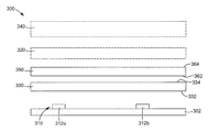
직하형 디스플레이 시스템(100)의 일 실시 형태의 개략 단면도가 도 1에 도시되어 있다. 그러한 디스플레이 시스템(100)은 예를 들어 LCD 모니터 또는 LCD-TV에 사용될 수 있다. 디스플레이 시스템(100)은 LC 패널(150), 및 LC 패널(150)에 조명 광을 제공하도록 위치된 조명 조립체(101)를 포함한다. LC 패널(150)은 전형적으로 패널 판(154)들 사이에 배치된 LC 층(152)을 포함한다. 판(154)은 종종 유리로 형성되고, LC의 층(152) 내의 액정의 배향을 제어하기 위해 그것의 내측 표면 상에 전극 구조물 및 정렬 층을 포함할 수 있다. 이들 전극 구조물은 통상적으로 LC 패널 픽셀, 즉 액정의 배향이 인접 영역과 독립적으로 제어될 수 있는 LC 층의 영역을 한정하도록 배열된다. LC 패널(150)에 의해 디스플레이된 이미지 상에 색상을 부여하기 위한 컬러 필터가 또한 하나 이상의 판(152)과 함께 포함될 수 있다.A schematic cross-sectional view of one embodiment of a
LC 패널(150)은 상부 흡수 편광기(156) 및 하부 흡수 편광기(158) 사이에 위치된다. 예시된 실시 형태에 있어서, 상부 및 하부 흡수 편광기(156, 158)는 LC 패널(150)의 외측에 위치된다. 조합된 흡수 편광기(156, 158) 및 LC 패널(150)은 백라이트(108)로부터 디스플레이 시스템(100)을 통한 관찰자로의 광의 투과를 제어한다. 예를 들어, 흡수 편광기(156, 158)는 이들의 투과 축들이 서로 직각인 상태로 배열될 수 있다. 비활성 상태에서, LC 층(152)의 픽셀은 이를 통과하는 광의 편광을 변화시키지 않을 수 있다. 따라서, 하부 흡수 편광기(158)를 통과하는 광은 상부 흡수 편광기(156)에 의해 흡수된다. 픽셀이 활성된 때, 이 픽셀을 통과하는 광의 편광은 회전되어, 하부 흡수 편광기(158)를 통해 투과되는 광의 적어도 일부가 또한 상부 흡수 편광기(156)를 통해 투과되게 한다. 예를 들어 제어기(104)에 의한 LC 층(152)의 상이한 픽셀들의 선택적 활성은 광이 소정의 요구되는 위치에서 디스플레이 시스템(100) 외부로 통과하게 하여서, 관찰자가 볼 수 있는 이미지를 형성한다. 제어기(104)는 예를 들어 텔레비전 이미지를 수신하여 디스플레이하는 컴퓨터 또는 텔레비전 제어기를 포함할 수 있다.
선택 사양인 하나 이상의 층(157)이 예를 들어 디스플레이 표면에 대한 기계적 및/또는 환경적 보호를 제공하기 위해 상부 흡수 편광기(156) 위에 제공될 수 있다. 하나의 예시적인 실시 형태에 있어서, 층(157)은 상부 흡수 편광기(156) 위에서 하드코트(hardcoat)를 포함할 수 있다.Optional one or
몇몇 유형의 LC 디스플레이들은 전술된 것과는 다른 방식으로 작동할 수 있음을 이해할 것이다. 예를 들어, 흡수 편광기는 평행하게 정렬될 수도 있고, LC 패널은 비활성 상태일 때 광의 편광을 회전시킬 수도 있다. 여하튼, 그러한 디스플레이의 기본 구조는 전술된 것과 유사한 채로 있다.It will be appreciated that some types of LC displays may operate in a different manner than described above. For example, the absorbing polarizers may be aligned in parallel, and the LC panel may rotate the polarization of light when inactive. In any case, the basic structure of such a display remains similar to that described above.
조명 조립체(101)는 백라이트(108), 및 백라이트(108)와 LC 패널(150) 사이에 위치된 하나 이상의 광 관리 필름(140)을 포함한다. 디스플레이 시스템(100)의 백라이트(108)는 LC 패널(150)을 조명하는 광을 발생시키는 다수의 광원(112)을 갖는 광원 유닛(110)을 포함한다. 광원 유닛(110)은 반사 기판(102)에 근접하여 위치된다. LCD-TV 또는 LCD 모니터에 사용되는 광원(112)은 종종 디스플레이 시스템(100)의 높이를 따라 연장되는 선형의 냉음극 형광 램프이다. 그러나, 필라멘트 또는 아크 램프, LED, 평평한 형광 패널 또는 외부 전극 형광 램프와 같은 다른 유형의 광원이 사용될 수도 있다. 이러한 광원의 열거는 제한하거나 망라하고자 하는 것이 아니라 단지 예시적인 것이다.The
광원(112)이 개략적으로 도시되어 있다. 대부분의 경우, 이들 광원(112)은 소형 LED이다. 이와 관련하여, "LED"는 가시광이든, 자외광이든, 적외광이든지 간에 광을 발광하는 다이오드를 말한다. 이는 통상적인 것이든 초 방사성(super radiant) 종류의 것이든 간에 "LED"로서 시판되는 비간섭성의 싸여진 또는 캡슐화된 반도체 소자를 포함한다. LED가 자외광과 같은 비가시광을 발광한다면, 그리고 가시광을 발광하는 몇몇 경우에 있어서, LED는 단파장 광을 장파장 가시광으로 변환하기 위해 형광체를 포함하도록 패키지되어(또는 원격 배치된 형광체를 조명할 수도 있음), 몇몇 경우에 백색 광을 발광하는 장치가 얻어진다. "LED 다이"는 가장 기본적인 형태, 즉 반도체 가공 공정에 의해 제조된 개별 구성요소 또는 칩 형태의 LED이다. 구성요소 또는 칩은 소자를 활성시키기 위한 전력의 인가에 적당한 전기 접점을 포함할 수 있다. 구성요소 또는 칩의 개별 층 및 다른 기능 요소는 전형적으로 웨이퍼 규모로 형성되고, 완성된 웨이퍼는 이어서 개별적인 단품(piece part)으로 절단되어 다수의 LED 다이가 얻어진다. 전방-발광 및 측면-발광 LED를 비롯한 패키지된 LED의 추가 논의가 본 명세서에 제공된다.
필요하다면, 선형 CCFL 또는 열음극 형광 램프(hot cathode fluorescent lamp; HCFL)와 같은 다른 가시광 발광기가, 개별적인 LED 소스 대신에 또는 이에 더하여, 개시된 백라이트를 위한 조명원으로서 사용될 수 있다. 게다가, 예를 들어 상이한 스펙트럼을 방출하는 것과 같은 냉백색(cool white) 및 온백색(warm white) CCFL/HCFL을 포함한 (CCFL/LED)와 같은 혼성 시스템이 사용될 수 있다. 발광기의 조합은 광범위하게 변화할 수 있으며, LED들과 CCFL들, 그리고 예를 들어 다수의 CCFL들, 상이한 색상의 다수의 CCFL들, 및 LED들과 CCFL들 등의 복수개의 것들을 포함할 수 있다.If desired, other visible light emitters such as linear CCFLs or hot cathode fluorescent lamps (HCFLs) may be used as illumination sources for the disclosed backlights instead of or in addition to individual LED sources. In addition, hybrid systems such as (CCFL / LED) including, for example, cool white and warm white CCFL / HCFLs that emit different spectra can be used. The combination of light emitters can vary widely and can include LEDs and CCFLs, and a plurality of such as, for example, multiple CCFLs, multiple CCFLs of different color, and LEDs and CCFLs.
예를 들어, 몇몇 응용에 있어서, 도 1에 도시된 개별적인 광원(112)들의 열을 긴 원통형 CCFL과 같은 다른 광원으로, 또는 그 길이를 따라 광을 발광하고 (LED 다이 또는 할로겐 전구와 같은) 원격 능동 구성요소에 결합된 선형 표면 발광 도광체로 교체하고, 다른 광원의 열에서도 마찬가지로 하는 것이 바람직할 수 있다. 그러한 선형 표면 발광 도광체의 예가 미국 특허 제5,845,038호(런딘(Lundin) 등) 및 제6,367,941호(리아(Lea) 등)에 개시되어 있다. 섬유 결합 레이저 다이오드 및 다른 반도체 발광기가 또한 알려져 있으며, 이들 경우에 광섬유 도파관의 출력 단부는 개시된 재순환 캐비티 내에서의 출력 단부의 배치 또는 그렇지 않으면 백라이트의 출력 영역 후방에서의 출력 단부의 배치와 관련하여 광원으로 간주될 수 있다. 전구 또는 LED 다이와 같은 능동 구성요소로부터 받은 광을 발광하는 렌즈, 편향기, 좁은 도광체 등과 같은 작은 발광 영역을 갖는 다른 수동 광학 구성요소에도 또한 동일하게 해당된다. 그러한 수동 구성요소의 한 가지 예는 측면 발광 패키지된 LED의 성형된 인캡슐런트(molded encapsulant) 또는 렌즈이다.For example, in some applications, the rows of individual
몇몇 실시 형태에 있어서, 백라이트(108)는 연속적으로 백색 광을 발광하고, LC 패널(150)은 컬러 필터 매트릭스와 조합하여 (황색/청색(YB) 픽셀, 적색/녹색/청색(RGB) 픽셀, 적색/녹색/청색/백색(RGBW) 픽셀, 적색/황색/녹색/청색(RYGB) 픽셀, 적색/황색/녹색/청록색/청색(RYGCB) 픽셀 등과 같은) 다색 픽셀들의 군을 형성하여, 디스플레이된 이미지가 다색성이 된다. 대안적으로, 다색성의 이미지는 컬러 순차 기술(color sequential technique)을 사용하여 디스플레이될 수 있는데, 이 컬러 순차 기술에서는 색상을 만들기 위해 백색 광으로 LC 패널(150)을 연속적으로 후방 조명하고 LC 패널(150) 내의 다색 픽셀들의 군을 조절하는 대신에, (예를 들어, 적색, 오렌지색, 호박색, 황색, 녹색, 청록색, (로열 블루(royal blue)를 포함하는) 청색, 및 전술된 것과 같은 조합의 백색으로부터 선택된) 백라이트(108) 자체 내의 개별의 상이한 색상의 광원이 조절되어 백라이트가 빠른 반복적인 순서로 (예를 들어, 적색, 이어서 녹색, 이어서 청색과 같은) 공간적으로 균일한 색상의 광 출력을 발한다. 이어서, 이 색상 조절된 백라이트는 (임의의 컬러 필터 매트릭스 없이) 하나의 픽셀 어레이만을 갖는 디스플레이 모듈과 조합되고, 만약 조절이 관찰자의 시각 시스템 내에 일시적인 색상 혼합을 생성할 만큼 충분히 빠르다면, 픽셀 어레이는 백라이트와 동기식으로 조절되어 전체 픽셀 어레이에 걸쳐 (백라이트에 사용되는 광원을 가정하면) 전 범위의 달성가능한 색상을 생성한다. 필드 순차 디스플레이로서 또한 알려진 컬러 순차 디스플레이의 예는 미국 특허 제5,337,068호(스튜어트(Stewart) 등) 및 미국 특허 제6,762,743호(요시하라(Yoshihara) 등)에 기술되어 있다. 몇몇 경우에 있어서, 단색 디스플레이만을 제공하는 것이 바람직할 수 있다. 이들 경우에 있어서, 백라이트(108)는 하나의 가시 파장 또는 색상으로 주로 발광하는 특정 광원(source) 또는 필터를 포함할 수 있다.In some embodiments, the
백라이트(108)는 또한 LC 패널(150)로부터 멀어지는 방향으로 전파되는 광원(112)으로부터의 광을 반사하기 위한 반사 기판(102)을 포함할 수 있다. 반사 기판(102)은 또한 본 명세서에서 추가로 설명되는 바와 같이 디스플레이 시스템(100) 내에서 광을 재순환시키기에 유용할 수 있다.The
반사 기판(102)은 바람직하게는 향상된 패널 효율을 위해 아주 반사적이다. 예를 들어, 반사 기판(102)은 광원에 의해 발광된 가시광에 대해 적어도 90%, 95%, 98%, 또는 99% 이상의 평균 반사도를 가질 수 있다. 반사 기판(102)은 공간적으로 균일하든지 패턴화되든지 간에 현저한 경면 반사형, 확산형, 또는 조합된 경면 반사형/확산형 반사기일 수 있다. 몇몇 경우에 있어서, 반사 기판(102)은 고반사도의 코팅을 갖는 강성의 금속 기판, 또는 지지 기판에 적층된 고반사도의 필름으로부터 제조될 수 있다. 적합한 고반사도의 재료로는 쓰리엠 컴퍼니(3M Company)로부터 입수가능한 비퀴티 ESR 다층 중합체 필름(Vikuiti™ Enhanced Specular Reflector multilayer polymeric film); 0.01 ㎜(0.4 밀) 두께의 아이소옥틸아크릴레이트 아크릴산 감압 접착제를 사용하여 비퀴티 ESR 필름에 황산바륨이 로딩된 폴리에틸렌 테레프탈레이트 필름(0.05 ㎜(2 밀)의 두께)을 적층함으로써 제조된 필름(이 최종 라미네이트 필름은 본 명세서에서 "EDR Ⅱ" 필름으로 불림); 토레이 인더스트리즈, 인크.(Toray Industries, Inc.)로부터 입수가능한 E-60 시리즈 루미러(Lumirror™) 폴리에스테르 필름; 더블유.엘. 고어 앤 어소시에이츠, 인크.(W. L. Gore & Associates, Inc.)로부터 입수가능한 것과 같은 다공성 폴리테트라플루오르에틸렌(PTFE) 필름; 랩스피어, 인크.(Labsphere, Inc.)로부터 입수가능한 스펙트랄론(Spectralon™) 반사 재료; 알라노드 알루미늄-페레트룽 게엠베하 운트 코.(Alanod Aluminium-Veredlung GmbH & Co.)로부터 입수가능한 미로(Miro™) 양극산화 알루미늄 필름(미로 2 필름을 포함); 후루카와 일렉트릭 컴퍼니, 엘티디.(Furukawa Electric Co, Ltd.)로부터의 MCPET 고반사도 발포 시트류(foamed sheeting); 및 미츠이 케미칼즈, 인크.(Mitsui Chemicals, Inc.)로부터 입수가능한 화이트 레프스타(White Refstar™) 필름 및 MT 필름을 비제한적으로 포함한다.
반사 기판(102)은 사실상 평평하고 매끄러울 수 있거나, 광 산란 또는 혼합을 향상시키기 위해 그에 결합된 구조화된 표면을 가질 수 있다. 그러한 구조화된 표면은 (a) 반사 기판(102)의 반사 표면 상에, 또는 (b) 상기 반사 표면에 도포된 투명 코팅 상에 부여될 수 있다. 전자의 경우에, 구조화된 표면이 이미 형성된 기판에 고반사 필름이 적층될 수 있거나, 또는 고반사 필름이 (쓰리엠 컴퍼니로부터 입수가능한 비퀴티 DESR-M(Durable Enhanced Specular Reflector-Metal) 반사기와 같이 얇은 금속 시트와 같은) 평평한 기판에 적층되고 이어서 스탬핑(stamping) 작업과 같은 것으로써 구조화된 표면을 형성하는 것이 이어질 수 있다. 후자의 경우에, 구조화된 표면을 갖는 투명 필름이 평평한 반사 표면에 적층될 수 있거나, 또는 투명 필름이 반사기에 도포되고 이어서 후에 구조화된 표면이 투명 필름의 상부에 부여될 수 있다.
반사 기판(102)은 광원(들)(112)이 그 위에 장착되는 연속적인 단일 (그리고 중단되지 않은) 층일 수 있거나, 또는 분리된 단편으로 비연속적으로 또는 광원(112)이 통과하여 돌출할 수 있는 분리된 개구를 달리 연속 층 내에 포함하는 한 비연속적으로 구성될 수 있다. 예를 들어, 반사 재료의 스트립(strip)이 LED의 열이 그 위에 장착되는 기판에 도포될 수 있고, 각각의 스트립은 LED의 한 열로부터 다른 열로 연장하기에 충분한 폭을 가지며 백라이트 출력 영역의 대향 경계 사이에 걸치기에 충분한 길이 치수를 갖는다.The
백라이트(108)는 또한 광 손실을 감소시키고 재순환 효율을 향상시키기 위해 바람직하게는 고반사도의 수직벽을 안에 대거나 달리 이를 구비한, 백라이트(108)의 외측 경계를 따라 위치된 측면 및 단부(도시되지 않음)를 포함할 수 있다. 반사 기판(102)용으로 사용된 동일한 반사 재료가 이들 벽을 형성하기 위해 사용될 수 있거나, 또는 상이한 반사 재료가 사용될 수 있다. 예시적인 실시 형태에 있어서, 측벽은 확산 반사성이다.The
광 관리 유닛으로 또한 불릴 수 있는 광 관리 필름들의 배열(140)은 백라이트(108)와 LC 패널(150) 사이에 위치된다. 광 관리 필름(140)은 디스플레이 시스템(100)의 동작을 향상시키기 위해 백라이트(108)로부터 전파되는 조명 광에 영향을 미친다. 예를 들어, 광 관리 필름들의 배열(140)은 확산기(120)를 포함할 수도 있다. 확산기(120)는 광원(112)으로부터 수광된 광을 확산시키기 위해 사용되고, 이는 LC 패널(150) 상에 입사하는 조명 광의 균일도를 증가시킨다. 결과적으로, 이는 관찰자에 의해 인식된 이미지가 보다 균일하게 밝게 되도록 한다.An
확산층(120)은 임의의 적합한 확산 필름 또는 확산판일 수 있다. 예를 들어, 확산층(120)은 임의의 적합한 확산 재료 또는 재료들을 포함할 수 있다. 몇몇 실시 형태에 있어서, 확산층(120)은 유리, 폴리스틸렌 비드 및 CaCO3 입자를 포함하는 다양한 분산상을 가진 폴리메틸 메타크릴레이트(PMMA)의 중합체 매트릭스를 포함할 수 있다. 예시적인 확산기는 미국 미네소타주 세인트 폴 소재의 쓰리엠 컴퍼니로부터 입수가능한 쓰리엠 스카치칼 확산 필름(3M™ Scotchcal™ Diffuser Film), 유형 3635-30 및 3635-70을 포함할 수 있다.
광 관리 유닛(140)은 또한 반사 편광기(142)를 포함할 수도 있다. 광원(112)은 전형적으로 비편광 광을 생성하지만, 하부 흡수 편광기(158)는 단일 편광 상태를 투과시키기만 하며; 따라서 광원(112)에 의해 발생된 광의 대략 절반은 이를 통해 LC 층(152)으로 투과되지 않는다. 그러나, 반사 편광기(142)는 그렇지 않다면 하부 흡수 편광기(158)에서 흡수될 광을 반사하기 위해 사용될 수 있다. 결과적으로, 이 광은 반사 편광기(142)와 반사 기판(102) 사이에서 반사에 의해 재순환될 수 있다. 반사 편광기(142)에 의해 반사된 광 중 적어도 일부는 편광이 없어지고, 이어서 반사 편광기(142) 및 하부 흡수 편광기(158)를 통해 LC 층(152)으로 투과되는 편광 상태로 반사 편광기(142)에 복귀될 수 있다. 이러한 방식으로, 반사 편광기(142)는 LC 층(152)에 도달하는 광원(112)에 의해 발광된 광의 분량을 증가시키기 위해 사용될 수 있고, 이에 의해 보다 밝은 디스플레이 출력을 제공한다.
임의의 적합한 유형의 반사 편광기, 예를 들어 다층 광학 필름(multilayer optical film; MOF) 반사 편광기, 연속/분산상 편광기와 같은 확산 반사 편광 필름(diffusely reflective polarizing film; DRPF), 와이어 그리드 반사 편광기, 또는 콜레스테릭(cholesteric) 반사 편광기가 반사 편광기(142)를 위해 사용될 수 있다.Any suitable type of reflective polarizer such as a multilayer optical film (MOF) reflective polarizer, a diffuse reflective polarizing film (DRPF) such as a continuous / disperse phase polarizer, a wire grid reflective polarizer, or collet A cholesteric reflective polarizer can be used for the
MOF 및 연속/분산상 반사 편광기 둘 다는 직교 편광 상태로 광을 투과하면서 하나의 편광 상태의 광을 선택적으로 반사하기 위해 통상적으로는 중합체 재료들인 적어도 2개의 재료들 사이의 굴절률의 차이에 의존한다. MOF 반사 편광기의 몇몇 예가 공동 소유인 미국 특허 제5,882,774호(존자(Jonza) 등)에 기술되어 있다. MOF 반사 편광기의 구매가능한 예로는 쓰리엠 컴퍼니로부터 입수할 수 있는 확산면을 포함하는 비퀴티™ DBEF-D200 및 DBEF-D440 다층 반사 편광기를 들 수 있다.Both MOF and continuous / disperse phase reflective polarizers rely on the difference in refractive index between at least two materials, which are typically polymeric materials, to selectively reflect light in one polarization state while transmitting light in an orthogonal polarization state. Some examples of MOF reflective polarizers are described in commonly owned US Pat. No. 5,882,774 (Jonza et al.). Commercially available examples of MOF reflective polarizers include Viquity ™ DBEF-D200 and DBEF-D440 multilayer reflective polarizers, including diffusing surfaces available from 3M Company.
본 발명과 관련하여 유용한 DRPF의 예로는 예를 들어 공동 소유인 미국 특허 제5,825,543호(오우더커크(Ouderkirk) 등)에 기술된 연속/분산상 반사 편광기, 및 예를 들어 공동 소유인 미국 특허 제5,867,316호(칼슨(Carlson) 등)에 기술된 확산 반사 다층 편광기를 들 수 있다. 다른 적합한 유형의 DRPF가 미국 특허 제5,751,388호(라슨(Larson))에 기술되어 있다.Examples of DRPFs useful in connection with the present invention are continuous / disperse phase reflective polarizers described, for example, in co-owned U.S. Pat.No. 5,825,543 (Ouderkirk et al.), And for example co-owned U.S. Pat. Diffusely reflective multilayer polarizers described in Carlson et al.). Another suitable type of DRPF is described in US Pat. No. 5,751,388 (Larson).
본 발명과 관련하여 유용한 와이어 격자 편광기의 몇몇 예로는 예를 들어 미국 특허 제6,122,103호(퍼킨스(Perkins) 등)에 기술된 것을 들 수 있다. 와이어 격자 편광기는 특히 미국 유타주 오렘 소재의 막스텍 인크.(Moxtek Inc)로부터 상업적으로 구매가능하다.Some examples of wire lattice polarizers useful in connection with the present invention include those described, for example, in US Pat. No. 6,122,103 (Perkins et al.). Wire lattice polarizers are commercially available, in particular, from Moxtek Inc., Orem, Utah, USA.
본 발명과 관련하여 유용한 콜레스테릭 편광기의 몇몇 예로는 예를 들어 미국 특허 제5,793,456호(브로어(Broer) 등) 및 미국 특허 공개 제2002/0159019호(포코니(Pokorny) 등)에 기술된 것을 들 수 있다. 콜레스테릭 편광기는 종종 1/4 파장 지연층과 함께 출력 측에 제공되어, 콜레스테릭 편광기를 통해 투과된 광이 선형으로 편광된 광으로 변환되게 한다.Some examples of cholesteric polarizers useful in connection with the present invention are described, for example, in US Pat. No. 5,793,456 (Broer et al.) And US Patent Publication No. 2002/0159019 (Pokorny et al.). It can be mentioned. A cholesteric polarizer is often provided at the output side with a quarter wavelength retardation layer, causing the light transmitted through the cholesteric polarizer to be converted into linearly polarized light.
몇몇 실시 형태에 있어서, 편광 제어층(144)이 확산판(120)과 반사 편광기(142) 사이에 제공될 수 있다. 편광 제어층(144)의 예로는 1/4 파장 지연층 및 액정 편광 회전층과 같은 편광 회전층을 들 수 있다. 편광 제어층(144)은 재생된 광의 증가된 분량이 반사 편광기(142)를 투과하도록 반사 편광기(142)로부터 반사되는 광의 편광을 변화시키는 데 사용될 수 있다.In some embodiments, a
광 관리 필름들의 배열(140)은 또한 하나 이상의 휘도 향상층을 포함할 수 있다. 휘도 향상층은 디스플레이의 축에 더 가까운 방향으로 축외(off-axis) 광을 방향전환하게 하는 표면 구조를 포함하는 층이다. 이는 LC 층(152)을 통해 축상으로(on-axis) 전파되는 광의 양을 증가시키며, 따라서 시청자가 보는 이미지의 휘도가 증가된다. 휘도 향상층의 일 예는 굴절 및 반사를 통해 조명 광을 방향전환하는 다수의 프리즘형 릿지(prismatic ridge)를 갖는 프리즘형 휘도 향상층이다. 디스플레이 시스템(100)에 사용될 수 있는 프리즘형 휘도 향상층의 예로는 BEF Ⅱ 90/24, BEF Ⅱ 90/50, BEF ⅢM 90/50 및 BEF ⅢT를 포함한, 쓰리엠 컴퍼니로부터 입수가능한 비퀴티™ BEF Ⅱ 및 BEF Ⅲ 계열의 프리즘형 필름을 들 수 있다.The
도 1에 도시된 예시적인 실시 형태는 반사 편광기(142)와 LC 패널(150) 사이에 배치된 제1 휘도 향상층(146a)을 나타낸다. 프리즘형 휘도 향상층은 전형적으로 광학 이득(optical gain)을 일차원으로 제공한다. 선택적인 제2 휘도 향상층(146b)은 또한 제1 휘도 향상층(146a)의 프리즘 구조에 직교하게 배향된 프리즘 구조를 갖는 광 관리층들의 배열(140)에 포함될 수 있다. 그러한 구성은 디스플레이 시스템(100)의 광학 이득을 2차원으로 증가시킨다. 다른 예시적인 실시 형태들에 있어서, 휘도 향상층(146a, 146b)은 백라이트(108)와 반사 편광기(142) 사이에 위치될 수 있다.The exemplary embodiment shown in FIG. 1 shows a first
광 관리 유닛(140)의 상이한 층들은 독립하여 존재할 수 있다. 다른 실시 형태에 있어서, 예를 들어 공동 소유인 미국 특허 출원 제10/966,610 호(코(Ko) 등)에 논의된 바와 같이, 광 관리 유닛(140)의 2개 이상의 층들이 함께 적층될 수 있다. 다른 예시적인 실시예에 있어서, 예를 들어 공동 소유인 미국 특허 출원 제10/965,937호(겔센(Gehlsen) 등)에 기술된 바와 같이, 광 관리 유닛(140)은 갭(gap)에 의해 분리된 2개의 부 조립체(subassembly)를 포함할 수 있다.Different layers of the
도 1에 도시된 실시 형태의 디스플레이 시스템(100)은 본 명세서에 기술된 임의의 적합한 조명 조립체를 포함할 수 있다. 몇몇 실시 형태에 있어서, 백라이트(108)는 LC 패널(150)에 보다 균일한 조명 광을 제공하는 데에 도움을 줄 수 있는 하나 이상의 광 추출 요소를 포함할 수 있다.The
도 2는 적어도 하나의 광 추출 요소를 포함하는 조명 조립체(200)의 일 실시 형태의 개략 단면도이다. 도시된 바와 같이, 조명 조립체(200)는 반사 기판(202), 및 반사 기판(202)에 근접하여 위치된 광원 유닛(210)을 포함한다. 조립체(200)는 또한 선택적인 확산층(220)을 포함할 수 있는데, 상기 확산층은 제1 광 추출 요소(230)가 확산층(220)과 광원 유닛(210) 사이에 있도록 위치된다. 도 1에 도시된 실시 형태의 반사 기판(102), 광원 유닛(110) 및 확산층(120)에 대한 모든 설계 고려사항 및 가능성이 도 2에 도시된 실시 형태의 반사 기판(202), 광원 유닛(210) 및 선택적인 확산층(220)에 동일하게 적용된다. 조명 조립체(200)는 또한 제1 광 추출 요소(230)를 포함하는데, 상기 제1 광 추출 요소는 광원 유닛(210)이 제1 광 추출 요소(230)와 반사 기판(202) 사이에 있도록 위치된다. 그러나, 반사 기판(202)이 개구 또는 슬롯을 갖도록 구성되고 광원 유닛(210)이 반사 기판(202) 후방에 장착되어 각각의 광원으로부터의 광이 개구 또는 슬롯을 통과하도록 정렬되는 경우와 같은 다른 배열이 또한 가능하다. 또한, 몇몇 경우에 있어서, 단순히 반사 기판(202)을 생략하는 것이 허용가능할 수 있다.2 is a schematic cross-sectional view of one embodiment of a
광원 유닛(210)은 적어도 제1 광원(212a) 및 제2 광원(212b)을 포함한다(본 명세서에서 광원(212)으로 총칭된다). 2개의 광원이 도시되어 있지만, 광원 유닛(210)은 임의의 적합한 개수의 광원을 포함할 수 있다.The
몇몇 실시 형태에 있어서, 광원 유닛(210)은 반사 기판(202) 상에 위치될 수 있고, 대안적으로 광원 유닛(210)은 반사 기판(202)으로부터 이격될 수 있다. 다른 실시 형태에 있어서, 예를 들어 공동 소유이고 공계류 중인 미국 특허 출원 제11/018,608호(대리인 관리번호 제60116US002호); 제11/018,605호(대리인 관리번호 제60159US002호); 제11/018,961호(대리인 관리번호 제60390US002호); 및 제10/858,539호(대리인 관리번호 제59334US002호)에 기술된 바와 같이, 광원 유닛(210)은 반사 기판(202) 상에 위치되거나 반사 기판(202)에 부착된 광원을 포함할 수 있다.In some embodiments, the
예를 들어 도 1의 광원(112)과 같은 임의의 적합한 유형의 광원(212)이 도 2에 도시된 실시 형태에 사용될 수 있다. 광원(212)은 임의의 적합한 배열로 반사 기판(202) 상에 위치될 수 있다. 예를 들어, 광원(212)은 육각형 패턴 또는 다른 기하학적 형상 패턴과 같은 비선형 어레이로, 또는 불균일(예를 들어, 랜덤 또는 세미-랜덤(semi-random)) 어레이로 배열될 수 있다. 도 6은 다수의 광원 유닛(610)을 포함하는 백라이트(600)의 일 실시 형태의 개략 평면도이다. 도시된 실시예에 있어서, 광원 유닛(610)은 바아(bar)로서 구성되고, 각각의 광원 유닛은 엇갈린 위치에 위치될 수 있는 다수의 광원(612a, 612b, 612c)을 포함한다. 광원 유닛(610)들은 상이한 형상을 가질 수 있다. 게다가, 광원(612a 내지 612c)들은 상이한 색상 또는 파장의 광을 생성할 수 있다. 예컨대, 몇몇 광원(612a)들은 적색 광을 생성할 수 있으면서, 다른 광원(612b)들은 녹색광을 생성하고 다른 광원(612c)들은 청색광을 생성한다. 상이한 색상의 광원(612a 내지 612c)들은 상이한 색상의 광이 혼합되는 정도를 증가시키도록 배열되고, 이에 의해 요구되는 색상 균일성을 갖는 혼합광을 생성할 수 있다. 다른 실시 형태에 있어서, 광원(612a 내지 612c)은 각각 백색 광을 생성할 수 있다. 또한, 몇몇 실시 형태에 있어서, 광원(612a 내지 612c)은 광원(612a 내지 612c)이 독립적으로 제어가능하도록 제어기에 전기 접속될 수 있다.For example, any suitable type of light source 212, such as
도 2로 돌아가면, 광원 유닛(210)은 상이한 파장 또는 색상의 조명 광을 발광하는 광원(212)을 포함할 수 있다. 예를 들어, 광원 유닛(210)은 제1 파장의 조명 광을 발광하는 제1 광원(212a), 및 제2 파장의 조명 광을 발광하는 제2 광원(212b)을 포함할 수 있다. 제1 파장은 제2 파장과 동일하거나 이와 상이할 수도 있다. 광원 유닛(210)은 또한 제3 파장의 광을 발광하는 제3 광원(도시되지 않음)을 포함할 수 있다. 몇몇 실시 형태에 있어서, 광원 유닛(210)의 여러 광원(212)은 혼합될 때 디스플레이 패널 또는 다른 장치에 백색 조명 광을 제공하는 광을 생성할 수 있다. 다른 실시 형태에 있어서, 광원(212)은 각각 백색 광을 생성할 수 있다.2, the
제1 광 추출 요소(230)는 광원 유닛(210)이 제1 광 추출 요소(230)와 반사 기판(202) 사이에 있도록 위치된다. 제1 광 추출 요소(230)는 광원 유닛(210)으로부터의 광 중 적어도 일부를 수광하고, 그러한 광을 균일한 강도 및/또는 색상을 제공하는 방식으로 반사 기판(202)로부터 멀어지는 방향으로 지향시키도록 작동가능하다.The first
기능적 갭은 확산층(220)으로부터 광원 유닛(210)을 분리한다. 이와 관련하여 "기능적 갭"은 (예를 들어, 입력 평면에서) 공간 내로 진입하는 광이 (예를 들어, 출력 평면에서(여기서, 입력 및 출력 평면은 공간의 주 경계 또는 표면을 형성함)) 공간을 빠져 나가는 시간까지 사실상 측방향으로 퍼질 수 있게 하기에 적당한 두께를 갖는 공간을 말한다. 따라서, 일반적으로, "기능적 갭"은 그 광학 두께 및 갭 내로 진입하는 광의 시준 정도(degree of collimation) 둘 모두에 따라 좌우된다. 광 추출 요소(230)의 존재는 기능적 갭을 광원 유닛(210)과 추출 요소(230) 사이의 제1 갭과, 추출 요소(230)와 확산층(220) 사이의 제2 갭으로 분할한다. 몇몇 경우에 있어서, 이들 제1 및 제2 갭 각각은 또한 기능적 갭이다.The functional gap separates the
예를 들어, 고 입사각 광을 우선적으로 발광하는 측면 발광 광원(예를 들어 미국 캘리포니아주 새너제이 소재의 루밀레즈 라이팅(Lumileds Lighting)으로부터 입수가능한 측멸 발광 LED 패키지, 또는 고 입사각으로 추출 요소 상으로 광을 투사하도록 장착된 다른 광원)이 광원(212)으로서 사용된 경우, 제1 및 제2 갭을 동일한 또는 유사한 두께의 2개의 기능적 갭으로 만드는 것이 바람직하다.For example, side-emitting light sources that preferentially emit high incident angle light (e.g., a stray light emitting LED package available from Lumileds Lighting, San Jose, Calif., Or light onto the extraction element at high incident angles). When another light source mounted to project light) is used as the light source 212, it is desirable to make the first and second gaps into two functional gaps of the same or similar thickness.
다른 경우에 있어서, 제1 및 제2 갭 중 하나만이 기능적 갭이고, 다른 갭은 하나의 광학 필름이 다른 광학 필름의 상부에 놓일 때 통상적으로 형성되는 미세 공기 갭과 같이 가능한 한 얇게 되도록, 구성요소를 장착하는 것이 바람직할 수 있다. 예를 들어, 제1 갭은 추출 요소(230)를 반사 기판(202)에 매우 근접하게 배치함으로써 거의 제거될 수 있다. 이는 램버시안(Lambertian) 발광 LED 또는 보다 높은 각도의 발광을 갖는 다른 전방 발광 LED에서와 같이 광원이 전방 방향으로 광을 우선적으로 발광하는 때에 유용할 수 있다. 그러한 배열은 추출 요소와 확산층 사이의 제2 갭을 최대화할 것이다. 광원이 반사 기판(202) 내에 형성된 리세스(recess) 또는 웰(well) 내에 장착된다면, 추출 요소(230)를 반사 기판(202) 바로 위에 장착하는 것이 또한 가능하다. 리세스의 경우에, 리세스는 선택적으로 반사 재료로 제조될 수 있다. 다른 극단적인 것은 추출 요소(230)를 확산층(220)에 맞닿아 배치하는 것과 같이 제1 갭은 최대화되고 제2 갭은 거의 제거되는 경우이다. 이는 단순히 이들 2개의 층을 물리적으로 접촉되게 배치하여 그들 사이에 미세 공기 갭을 남겨둠으로써, 또는 얇은 접착제층을 사용하여 추출 요소(230)를 확산층(220)에 부착시킴으로써 수행될 수 있다. 패키지된 LED를 장착하는 것에 의한 것과 같이 광원 유닛(210)의 광원(212)이 반사 기판(202) 위로 돌출할 수 있어, 그들의 인캡슐런트 렌즈가 반사 기판 위로 연장하게 됨을 알아야 한다.In other cases, only one of the first and second gaps is a functional gap and the other gap is as thin as possible, such as a micro air gap that is typically formed when one optical film is placed on top of another optical film. It may be desirable to mount it. For example, the first gap can be nearly eliminated by placing the
이제 광 추출 요소(230)로 관심을 돌리면, 상기 요소는 제1 주 표면(232) 및 제2 주 표면(234)을 포함한다. 도시된 실시 형태에 있어서, 제1 주 표면(232)은 광원 유닛(210)에 면하는 광 추출 표면을 포함한다. 대안적으로, 다른 실시 형태에 있어서, 광 추출 요소(230)의 제2 주 표면(234)은 광 추출 표면을 포함한다. 또한, 몇몇 실시 형태에 있어서, 제1 주 표면(232) 및 제2 주 표면(234) 둘 모두는 광 추출 표면을 포함할 수 있다.Turning now to the
광 추출 요소(230)는 광 추출 표면을 제공하기 위해 내부에 구조물이 형성된 광 추출 필름 또는 층을 포함할 수 있거나, 광 추출 요소(230)는 본 명세서에서 추가로 기술되는 바와 같이 기판에 부착된 구조물을 갖는 필름을 포함할 수 있다.The
적합한 필름 및 구조물은 광원 유닛(210)으로부터 광을 추출하는 구조화된 표면 등을 형성하도록 배열된 미소 구조물을 갖는 필름 등을 포함할 수 있다. 필름의 일측 또는 양측은 그러한 구조화된 표면을 가질 수 있다. 유용한 구조물은 선형 프리즘, 피라미드형 프리즘, 원뿔체 및 타원체를 포함하고, 상기 구조물은 표면으로부터 외향 연장하는 돌기 또는 표면 내로 연장하는 피트(pit) 형태일 수 있다. 구조물의 크기, 모양, 기하학적 형상, 배향 및 간격은 모두 광 추출 요소(230)의 성능을 최적화하도록 선택될 수 있고, 개별 구조물은 대칭 또는 비대칭일 수 있다. 구조화된 표면은 균일하거나 균일하지 않을 수 있고, 후자의 경우에 이러한 구조물의 위치 및 크기 둘 모두는 랜덤 또는 의사 랜덤할 수 있다. 몇몇 실시 형태에 있어서, 구조화된 표면은 반복하는 구조물 패턴을 포함할 수 있다. 크기, 모양, 기하학적 형상, 배향 및/또는 간격의 주기적인 또는 유사 랜덤한 변화에 의한 분열 규칙 특징부는 백라이트의 색상 및/또는 휘도 균일성을 조정하기 위해 사용될 수 있다. 몇몇 경우에 있어서, 보다 작은 구조물이 대체로 광원 위로 정렬되고 보다 큰 구조물이 다른 곳에 위치되도록, 작은 구조물 및 큰 구조물의 분포를 갖고 필름을 위치시키는 것이 유익할 수 있다. 몇몇 실시 형태에 있어서, 구조물은 구조물들 사이에서 최소한의 랜드(land)가 있도록(사실상 랜드가 없는 배열을 포함) 조밀하게 패킹될 수 있다.Suitable films and structures may include films and the like having microstructures arranged to form structured surfaces and the like that extract light from
적합한 광 추출 필름의 예는 모두 쓰리엠 컴퍼니로부터 입수가능한 비퀴티™ BEF(brightness enhancement film), 비퀴티™ TRAF(transmissive right angle film), 비퀴티™ IDF(image directing film) 및 비퀴티™ OLF(optical lighting film)와 같은 상용 일차원(선형) 프리즘형 중합체 필름뿐만 아니라 종래의 렌즈 모양의 선형 렌즈 어레이를 포함한다. 이들 일차원 프리즘형 필름이 개시된 직하형 백라이트에서 광 추출 필름으로서 사용될 때, 프리즘형 구조화된 표면이 광원 유닛(210)에 면하는 것이 통상적으로 바람직하다.Examples of suitable light extraction films are all Viquity ™ brightness enhancement film (BEF), Biquity ™ transmissive right angle film (TRAF), Viquity ™ image directing film (IDF) and Viquity ™ optical (OLF), all available from 3M Company conventional lenticular linear lens arrays as well as commercial one-dimensional (linear) prismatic polymer films such as lighting films). When these one-dimensional prismatic films are used as light extraction films in the disclosed direct backlight, it is usually desirable for the prismatic structured surface to face the
구조화된 표면이 2차원 특성을 갖는 광 추출 필름의 추가 예는 미국 특허 제4,588,258호(후프만(Hoopman)), 제4,775,219호(에펠돈(Appeldorn) 등), 제5,138,488호(스즈크젝(Szczech)), 제5,122,902호(벤슨(Benson)), 제5,450,285호(스미스(Smith) 등) 및 제5,840,405호(슈스타(Shusta) 등)에 개시된 것과 같은 입방체 코너 표면 구성; 미국 특허 제6,287,670호(벤슨(Benson) 등) 및 제6,280,822호(스미스 등)에 기술된 것과 같은 반전 프리즘 표면 구성; 미국 특허 제6,752,505호(파커(Parker) 등) 및 미국 특허 공개 제2005/0024754호(엡스테인(Epstein) 등)에 개시된 구조화된 표면 필름; 및 예를 들어 기무라(Kimura) 등의 미국 특허 제6,771,335호에 기술된 것과 같은 비드형 시트류(beaded sheeting)를 포함한다.Further examples of light extraction films in which the structured surface has two-dimensional properties are described in US Pat. Nos. 4,588,258 (Hoopman), 4,775,219 (Appeldorn et al.), 5,138,488 (Szczech). Cubic corner surface configurations such as those disclosed in US Pat. Nos. 5,122,902 (Benson), 5,450,285 (Smith et al.) And 5,840,405 (Shusta et al.); Inverted prism surface configurations such as those described in US Pat. Nos. 6,287,670 (Benson et al.) And 6,280,822 (Smith et al.); Structured surface films disclosed in US Pat. No. 6,752,505 (Parker et al.) And US Patent Publication No. 2005/0024754 (Epstein et al.); And beaded sheeting such as, for example, described in US Pat. No. 6,771,335 to Kimura et al.
하나의 예시적인 광 추출 필름이 도 7a에 도시되어 있다. 광 추출 필름(700)은 프리즘(702)의 어레이를 포함한다. 각각의 프리즘은 x-z 평면 및 y-z 평면 둘 모두에서 아크(arc)를 형성하는 4개의 만곡형 또는 아크형 면을 포함한다. 예를 들어, 프리즘(704)은 정점(714)에서 만나는 4개의 면(706, 708, 710, 712)을 갖는다. 정점(714)은 뾰족한 피크(peak)가 아니다. 대신에, 정점(714)은 x방향 및 y방향 둘 모두로 연장하는 아크 곡선의 교차에 의해 형성된, 상당히 둥근 표면을 갖는다. 도 7a는 각각의 프리즘을 x-z 평면 및 y-z 평면 둘 모두에서 대칭인 것으로서 도시하지만, 광 추출 필름(700)은 하나의 평면에서만, 예를 들어 x-z 평면에서만 대칭인 프리즘을 포함할 수 있다. 이러한 비대칭은 프리즘이 z축으로부터 기울어지게 할 것이다. 필름(700)은 미국 특허 공개 제2005/0024754 A1호(엡스테인 등)에 기술된 기술을 사용하여 제조될 수 있다.One exemplary light extraction film is shown in FIG. 7A. The
광 추출 필름(700)의 프리즘(702)은 x-y 평면 내의 밑면을 위해 임의의 적합한 형상, 예를 들어 정사각형, 사변형(예를 들어, 사다리꼴, 마름모, 평행사변형, 직사각형)을 포함할 수 있다. 마름모의 형상을 취하는 밑면에 대해, 마름모는 임의의 적합한 길이를 포함하는 2개의 대각선 및 2개의 대각선들 사이의 길이의 비를 포함할 수 있다. 본 명세서에 사용되는 바와 같이, 마름모와 관련한 "대각선"이라는 용어는 다각형의 임의의 모서리에 의해 만나지 않는, 즉 인접하지 않은 다각형의 임의의 2개의 꼭지점을 잇는 선을 말한다. 몇몇 실시 형태에 있어서, 장사방형의 밑면을 갖는 프리즘(704)의 2개의 대각선은 2:1의 비를 가질 수 있다. 게다가, 밑면의 꼭지점은 둥글거나 또는 뾰족하게 형성될 수 있다.The
프리즘(702)은 프리즘 사이에 최소한의 랜드가 존재하도록 조밀하게 패킹될 수 있고; 대안적으로 프리즘(702)은 필름(700)이 프리즘(702)들 사이에 랜드를 포함하도록 임의의 적합한 거리만큼 이격될 수 있다.
다른 예시적인 광 추출 필름이 도 7b의 부분 사시도에 도시되어 있다. 여기서, 필름(720)은 매끄러운 표면(724)에 대향하여 배치된 구조화된 표면(722)을 갖는다. 구조화된 표면(722)은 긴 프리즘(726)들의 어레이를 포함한다. 프리즘(726)들은 연속적이거나 비연속적일 수 있으며, 사실상 연속적인 프리즘이 특히 바람직하다. 이와 관련하여, 사실상 연속적이라는 것은 각각의 프리즘(726)이 광 추출 필름의 전체 길이로 연장하는 것을 의미한다. 각각의 프리즘의 높이 및 폭은 광범위하게 변할 수 있고, 도 7b에 도시된 실시 형태에 있어서, 각각의 프리즘은 프리즘의 길이를 따라 기복이 있는 높이 및 폭을 갖는다. 상기 기복은 각각의 프리즘(726)의 길이를 따라 연속적으로 배열된 교번하는 주 부분(major portion)(727) 및 부 부분(minor portion)(729)을 형성하기에 실질적으로 충분하다. 이러한 실질적인 기복은 구조화된 표면의 평면(x-y 평면) 내의 구조화된 표면에 곡률을 부가하며, 이는 아래에서 추가로 논의되는 바와 같이 필름이 광원에 대해 적당하게 배향되는 경우에, 즉 필름의 구조화된 표면(722)이 광원에 면하는 상태에서, 제어된 방식으로 필름에 의해 투과된 광을 소정의 방위각 범위로 퍼지게 하는 것을 도울 수 있다. 또한, 이 실시 형태에 있어서, 인접한 프리즘(726)들은 주어진 프리즘의 부 부분(729)이 그의 인접한 프리즘의 주 부분(727)에 의해 측면을 접하게 되고, 주어진 프리즘의 주 부분(727)이 그의 인접한 프리즘의 부 부분(729)에 의해 측면을 접하게 되도록 서로에 대해 위상차(out-of-phase)가 있거나 시프트되어 있지만, 그러한 위상차 배열은 요구되지 않는다. 이 실시 형태에 있어서, 프리즘은 프리즘들 사이에서 사실상 개재하는 평평한 랜드 영역이 없이 연속적인 연쇄 어레이를 형성한다. 그러나, 그러한 연쇄 배열은 요구되지 않는다 - 즉, 최소한의 랜드 영역이 바람직하지만, 약간의 랜드 영역이 프리즘들 사이에 존재할 수 있다. 프리즘 밑면의 형상 또는 윤곽은 바람직하게는 이러한 연쇄(예를 들어, 도 7b 및 도 7c에 도시된 바와 같음)를 허용하도록 대칭을 취하여, 사실상 동일한 형상의 2개의 프리즘(726)이 사실상 그들 사이에 랜드 또는 갭 없이 공통 경계를 따라 정합할 수 있게 한다. 프리즘(726) 각각은 연속적인 기복 릿지(ridge, 728)를 형성하도록 만나는 2개의 경사진 표면을 포함한다.Another exemplary light extraction film is shown in a partial perspective view of FIG. 7B. Here, the
필름(720) 및 그의 구조화된 표면(722)의 부분 평면도가 도 7c에 도시되어 있고, 절단선 7d-7d 및 7e-7e를 따른 대응하는 단면도가 도 7d 및 도 7e에 각각 제공되어 있다. 이들 도면에 있어서, 프리즘(726)이 전술된 연쇄 대칭을 취하지만, 각각의 프리즘(726)은 각각의 프리즘의 2개의 경사진 표면의 상이한 크기 및 (x-y 평면 또는 표면(724)에 대한) 상이한 경사에 의해 도시된 바와 같이 구조적 비대칭을 가져, 이들 사이에 형성된 기복 릿지(728)가 x-z 평면 내에, 또는 구조화된 표면(722) 전체 또는 표면(724)에 직각인 임의의 평면 내에 있지 않게 된다는 것을 보다 명확하게 볼 수 있다. 대신에, 릿지(728)는 도 7d에 가장 잘 도시된 바와 같이 사실상 x-z 평면에 대해 각도(θ)로 경사진 평면 내에 있는데, 각도(θ)는 프리즘의 경사 정도의 척도이다. 이러한 프리즘 경사의 다른 결과는 주어진 프리즘의 연속적인 릿지(728)가 평면도에서 선형이 아니라 대신에 기복이 있다는 것이다. 광학 성능 관점으로부터, 프리즘 경사는 구조화된 표면이 x-z 평면에 대해, 즉 필름(720)에 수직이고 프리즘 방향에 평행한 평면에 대해 비대칭인 광 추출 특성을 갖도록 할 수 있다. 이는 바람직할 수 있거나 필름의 의도된 응용에 좌우되지 않을 수 있다. 프리즘은 또한 y-z 평면에 대해 기울어짐 또는 경사를 나타낼 수 있는데, 여기서 그러한 기울어짐 또는 경사는 x-z 평면에서 측정됨을 알아야 한다.A partial plan view of the
전술된 바와 같이, 프리즘(726)은 프리즘의 길이를 따라 식별가능한 주 부분 및 부 부분(727, 729)을 형성하기에 충분히 기복이 있는 높이 및 폭을 갖는다. 도 7c에서, 프리즘(726)의 최소 및 최대 폭은 Wmax 및 Wmin으로 각각 부호가 붙어 있다. Wmax/Wmin 비는 예를 들어 적어도 2, 5, 10, 또는 20 이상일 수 있다. 이 점과 관련하여 폭은 프리즘의 길이에 직각으로 그리고 하나의 경사진 프리즘 표면의 외측 경계 또는 모서리로부터 나머지 하나의 경사진 프리즘 표면의 외측 경계 또는 모서리까지 측정된다. 도 7c에서, Wmax/Wmin는 약 20이다. 프리즘(726)의 높이는 또한 최대 높이 Hmax와 최소 높이 Hmin 사이에서 기복이 있다. 이 점과 관련하여 높이는, 프리즘을 따라 임의의 주어진 지점에서, 구조화된 표면 상의 최하위 지점 또는 정점으로부터 프리즘의 릿지(728) 또는 다른 최상부까지 z축을 따라 측정된다. Hmax/Hmin 비는 예를 들어 적어도 2, 5, 10, 또는 20 이상일 수 있다. 도 7d 및 도 7e에서, Hmax/Hmin는 약 20이다. 바람직하게는, 도 7e에 가장 잘 도시된 바와 같이, 높이는 균일하게 기복이 있어 릿지(728)의 인접 최대값들 또는 인접 최소값들 사이에 특성적인 길이(λ)를 제공한다.As described above, the
평면내 종횡비는 λ/Wmax의 비로 정의될 수 있다. 이 종횡비를 선택함에 있어서 넓은 허용 범위가 있지만, 예시적인 실시 형태에서 종횡비는 약 1 내지 5의 범위이다. 구조화된 표면(722)에 대한 종횡비는 약 2이다.The in-plane aspect ratio can be defined as the ratio of λ / Wmax. While there is a wide tolerance in selecting this aspect ratio, in an exemplary embodiment the aspect ratio is in the range of about 1-5. The aspect ratio for the
본 명세서에서 "방위각방향 빔 확대 토포그래피"로 언급되는 도 7b 내지 도 7e에서 전술된 이러한 표면 토포그래피는, 광 추출 필름이 개별 광원들의 어레이와 확산판 사이의 갭 내에 위치되고 이들 광원에 의해 발광된 광을 확산판 상으로 균일하게 퍼지게 하기 위해 광 추출 필름의 구조화된 표면이 광원에 면하는 직하형 백라이트 시스템에서, 특별한 유용성을 갖는다.Such surface topography, described above in FIGS. 7B-7E, referred to herein as "azimuth beam expanding topography", means that a light extraction film is positioned in the gap between an array of individual light sources and a diffuser plate and emits light by these light sources. In a direct backlight system in which the structured surface of the light extraction film faces the light source in order to spread the light evenly onto the diffuser plate, it has particular utility.
도 7a 및 도 7e에서 전술된 토포그래피는 단지 예시적인 것이며, 의도된 응용에 따라 많은 다른 광 추출 표면 설계가 사용될 수 있다. 예를 들어, 다른 예시적인 광 추출 표면 설계가, 본 명세서에 참고로 포함된 이하의 공보, 즉 국제특허공개 WO 2005/120791호, 국제특허공개 WO 2006/031483호, 미국 특허 공개 제2005/0122591호, 미국 특허 공개 제2005/0280752호 및 미국 특허 공개 제2006/0092490호에 나타나 있다.The topography described above in FIGS. 7A and 7E is merely exemplary, and many other light extraction surface designs may be used depending on the intended application. For example, other exemplary light extraction surface designs are described in the following publications, which are incorporated herein by reference, ie WO 2005/120791, WO 2006/031483, US Patent Publication 2005/0122591 US Patent Publication No. 2005/0280752 and US Patent Publication No. 2006/0092490.
참고 목적을 위해, 도 12는 x-y-z 직교좌표계 상에 중첩된 α-β-z 극좌표계를 도시한다. 광 추출 필름 상에 입사하는 시준된 입력 광선의 방향을 나타내기 위해 z축을 따라 단위 벡터(1210)를 선택하는 것이 편리하다. 입사광 방향이 추출 필름에 직각이면, 이때 필름은 x-y 평면에 의해 표현될 수 있다. 추출 필름에 의해 전환된 광의 방향은, 단순한 경우에, 단위 구(unit sphere, 1214)(구의 상부 반구만이 도면에 도시됨) 상의 다른 단위 벡터(1212)에 의해 동일한 좌표계 상에서 표현될 수 있다. 따라서, 전환된 광의 방향은 극좌표(α, β)에 의해 특정될 수 있는데, 여기서 α 는 z축으로부터 측정된 극각(polar angle)(0 내지 90도 또는 0 내지 π/2 라디안의 가능한 값을 가짐)이며, β는 x축과 단위 벡터(1210, 1212)를 포함하는 평면 사이에서 측정된 방위각(0 내지 360도 또는 0 내지 2π 라디안의 가능한 값을 가짐)이다.For reference purposes, FIG. 12 shows the α-β-z polar coordinate system superimposed on the x-y-z rectangular coordinate system. It is convenient to select the
본 명세서에 개시된 광 추출 필름은 시준된 입사광 빔(그 단면적은 광 추출 필름의 구조화된 표면의 대표 면적을 조명하기에 충분히 큼)을 하나 이상의 전환된 빔으로 전환한다. 예를 들어, 도 13a는 광 추출 필름(1312) 상에 수직으로 입사하는 시준된 입사광 빔(1310)을 도시하는데, 여기서 필름(1312)은 입사광에 면하는 구조화된 표면 및 매끄러운 대향 표면을 갖는 종래의 BEF 필름이며, 구조화된 표면은 x축에 평행하게 연장하는 단순한 선형 프리즘의 어레이를 갖는다. 프리즘의 (평평한) 각진 면(facet)은 입사광을 편향시켜 z축에 대해 동일한 각도(1315, 1317)로 지향된 편향 빔(1314, 1316)을 생성한다. 구조화된 표면은 프리즘들 사이에 어떠한 사실상 평평한 랜드 영역도 없기 때문에, 최초 방향인 z축을 따라 출력 빔의 거의 또는 전혀 관찰되지 않는다. 각도(1315, 1317)는 도 12의 각도(α)와 유사한 극각이다. 구조화된 표면 상의 프리즘 면들 사이의 끼인각을 맞춤 형성으로써, 각도(1315, 1317)는 변경될 수 있고, 빔의 다소간의 전환이 수행될 수 있다.The light extraction film disclosed herein converts a collimated incident light beam whose cross-sectional area is large enough to illuminate a representative area of the structured surface of the light extraction film into one or more converted beams. For example, FIG. 13A shows a collimated
그러나, 프리즘 면들 사이의 각도와 무관하게, 단순 선형 프리즘들의 어레이의 토포그래피는 별개의 두 방향을 따라 지향된 단지 2개의 전환된 빔만을 생성한다. 백라이트에 보다 많은 광 혼합 또는 블러링(blurring)을 달성하기 위해, 보다 많은 방향 전환이 필요하다면, 선형 프리즘의 면은 프리즘의 길이에 직각인 단면 평면에서 평평한 것으로부터 만곡된 것으로 변화될 수 있다. 그러한 곡률의 효과를 도 13b에서 볼 수 있는데, 여기서 종래의 BEF 필름(1312)은 평평한 프리즘 면에 y-z 평면에서 사실상 만곡이 주어진 것을 제외하고는 모든 면에서 필름(1312)과 유사한 광 추출 필름(1312a)으로 교체되었다. 곡률은 2개의 비중첩 범위에 걸쳐 y-z 평면에서 완만하게 변하는 표면 수직 방향을 생성하고, 이는 이어서 확대된 전환 빔(1314a, 1316a)을 생성한다. 빔(1314a, 1316a)은 각각 상당한 각도 범위에 걸쳐 (피크 강도(peak intensity)의 퍼센트와 같은 주어진 임계 광 강도 또는 배경 수준(background level)을 초과하여) 사실상 연속적으로 확장하기 때문에 "확대된"으로 언급된다. 도 13b의 경우에 있어서, 이들 각도는 빔(1314a)에 대해 1315a 내지 1315b의 범위이고, 빔(1316a)에 대해 1317a 내지 1317b의 범위이다. 그러나, 이들 모든 각도는 도 12의 각도(α)와 유사한 극각이고, 따라서 확대된 빔의 각도방향 폭은 전체적으로 극방향이다. 프리즘 면의 곡률은 방위각 방향으로 전환된 빔의 확대를 생성하지 않는다.However, irrespective of the angle between the prism faces, the topography of the array of simple linear prisms produces only two diverted beams directed along two separate directions. If more orientation is needed to achieve more light mixing or blurring in the backlight, the face of the linear prism can be changed from flat to curved in the cross-sectional plane perpendicular to the length of the prism. The effect of such curvature can be seen in FIG. 13B where the
이제 도 13c로 돌아가면, 방위각방향 빔 확대 토포그래피를 갖는 광 추출 필름의 거동을 도면에서 볼 수 있다. 도 13c는, 광 추출 필름(1312)이 도 7b 내지 도 7e와 관련하여 기술된 필름(720)과 사실상 동일한 광 추출 필름(1312b)으로 교체된 점을 제외하고는, 도 13a의 셋업과 유사하다. 필름(1312b)은 그의 구조화된 표면이 입사광에 면하고 프리즘이 x축에 평행하게 연장하도록 배향된다. 앞서 논의된 바와 같이, 구조화된 표면 상의 프리즘의 상당한 기복은 도 13b와 관련하여 도시된 직각인 y-z 평면 내의 곡률이라기보다는 구조화된 표면의 평면(x-y 평면) 내의 상당한 곡률을 생성한다. 이어서 이러한 평면내 곡률은 (x-y 평면 상으로 투사되는) 완만하게 변하는 표면 수직 방향의 결과로서 확대된 전환 빔(1314b, 1316b)을 생성하는 원인이 된다. 빔(1314b, 1316b)은 확대되되, 도면에서 볼 수 있는 바와 같이 극 편향 각도(1315c, 1317c)에 직각인 방위각 방향으로 확대된다. 방위각 방향에 있어서의 확대량은 구조화된 표면에 존재하는 평면내 곡률의 양에 의해 제어될 수 있는데, 이는 이어서 앞서 기술된 Wmax/Wmin, Hmax/Hmin 및 /λWmax 비에 의해 표시되는 바와 같이 기복의 심한 정도에 의해 제어될 수 있다.Turning now to FIG. 13C, the behavior of the light extraction film with the azimuthal beam expanding topography can be seen in the figure. FIG. 13C is similar to the setup of FIG. 13A, except that the
방위각방향 빔 확대를 나타낼 수 있는 다른 구조화된 표면이 도 14에 도시되어 있다. 여기서, 매끄러운 주 표면(1412) 및 대향한 구조화된 표면(1414)을 갖는 광 추출 필름(1410)의 일부분이 도시되어 있다. 구조화된 표면은 사행형(serpentine) 프리즘(1416)들의 연쇄 어레이를 포함하거나 이로 본질적으로 이루어지는데, 이들 각각은 광 추출 필름의 전체 길이에 걸쳐 연장할 수 있다. 구조화된 표면(722)(도 7b 내지 도 7e)의 프리즘(726)과 유사하게, 각각의 프리즘(1416)은 릿지를 형성하도록 만나는 2개의 경사진 프리즘 면을 포함한다. 그러나, 프리즘(726)과는 다르게, 각각의 프리즘(1416)은 사실상 일정한 폭과 높이를 유지하면서 y방향으로 전후로 기복이 있다. 기복은 바람직하게는, 프리즘들 사이에서 평평한 랜드 영역이 사실상 없이 사실상 동일한 프리즘들이 표면(1414) 상에 조밀하게 패킹될 수 있도록 프리즘(1416)에 연쇄 대칭을 제공하기 위해 선택된, 정형파 함수 또는 임의의 다른 완만하게 변하는 함수(또는 완만하지 않은 함수 또는 완만한 함수와 완만하지 않은 함수의 조합)일 수 있다. 도 7f의 셋업을 참조하면, 일정한 절삭 깊이를 유지하지만 방향(742)에 평행하게 마스터 공구를 요동시킴으로써, 프리즘을 생성하기 위한 홈이 마스터 공구 상에 만들어질 수 있다. 사행형 토포그래피는 구조화된 표면의 평면(x-y 평면)에 곡률을 생성하며, 곡률의 양은 기복의 심한 정도에 의해 제어될 수 있다. 평면내 곡률의 양은 구조화된 표면(1414)이 백라이트의 광원 유닛에 면하도록 필름(1410)이 배향될 때 방위각방향 빔 확대의 양을 제어하기 위해 사용될 수 있다.Another structured surface that can exhibit azimuthal beam magnification is shown in FIG. 14. Here, a portion of the
도 7b 내지 도 7e의 구조화된 표면(722) 및 도 14의 구조화된 표면(1414) 이외에, 방위각방향 빔 확대를 나타낼 수 있는 다른 구조화된 표면은 원뿔형 구조물들의 어레이이다. 원뿔형 구조물들은 삼각형, 다이아몬드 또는 육각형의 평면도 배열로 배치될 수 있고, 바람직하게는 광 추출 표면을 통한 수직 입사광의 직접(비전환) 투과를 사실상 피하기 위해 구조화된 표면에 평평한 랜드 영역이 전혀 없도록 조밀하게 패킹되고 교차한다.In addition to the
원뿔형 구조물의 밑면은 광 추출 표면의 x-y 평면 내에 있고, 구조물의 정점은 x-y 평면 외측에 있다. 밑면은 예를 들어 원형, 타원형 및 육각형을 비롯하여 매우 다양한 형상을 가질 수 있다. 정점을 형성하도록 교차하는 원뿔형 구조물의 변은 선형일 수 있거나 곡률을 포함할 수 있어서, 원뿔형 구조물은 구조화된 표면의 x-y 평면에 평행한 평면 내에서 원형 또는 타원형 단면을 가질 수 있다. 어레이 내의 각각의 원뿔체의 정점은 경사지거나 경사지지 않을 수 있다(즉, 정점은 x-y 평면에 수직인 평면 내에 또는 평면 외측에 있을 수 있다).The underside of the conical structure is in the x-y plane of the light extraction surface and the vertices of the structure are outside the x-y plane. The underside can have a wide variety of shapes, including for example round, oval and hexagonal. The sides of the conical structure that intersect to form a vertex can be linear or can include curvature such that the conical structure can have a circular or elliptical cross section in a plane parallel to the x-y plane of the structured surface. The vertex of each cone in the array may or may not be inclined (ie, the vertex may be in or out of the plane perpendicular to the x-y plane).
2개의 별개의 방위각 방향으로 확대된 출력 빔을 생기게 하는 구조화된 표면(722, 1414)의 2개의 별개의 (만곡된) 프리즘 면과 대조적으로, 원뿔형으로 구조화된 표면의 경우에, 구조화된 표면의 평면 내에 있어서의 곡률의 360° 연속은 방위 각도로 전체 360°를 커버하는 연속적인 링-형상의 출력 빔을 생성한다.In the case of a conical structured surface, in contrast to the two separate (curved) prism faces of the
원뿔형 구조물들의 어레이를 포함하는 광 추출 표면이 다양한 형태로 제공될 수 있지만, 중합체 필름이 도 2에 기술된 것과 같은 백라이트 LED 시스템에서의 사용에 특히 바람직하다. 그러한 필름은 예를 들어 ELMOF 장치를 사용하여 적당하게 형성된 공구를 형성함으로써 그리고 상기 공구를 이용하여 주조, 코팅 또는 압축 공정에 의해 중합체 필름을 제조함으로써 제조될 수 있다.Although light extraction surfaces comprising arrays of conical structures can be provided in various forms, polymer films are particularly preferred for use in backlight LED systems such as those described in FIG. 2. Such films can be produced, for example, by forming a suitably formed tool using an ELMOF apparatus and by using the tool to produce a polymer film by a casting, coating or compression process.
물론, 실질적인 방위각방향 빔 확대를 제공하도록 구성된 구조화된 표면은 또한 극방향 빔 확대(polar beam widening)를 생성하는 특징부를 포함할 수 있다. 따라서, 예를 들어 도 7b 내지 도 7e의 구조화된 표면(722), 도 14의 구조화된 표면(1414) 및 전술된 원뿔형 어레이 구조화된 표면에는 구조화된 표면의 평면에 직각인 평면에(예를 들어, 도 7b의 y-z 평면에 그리고 도 14의 y-z 평면에) 면 곡률이 제공될 수 있다. 도 7b 내지 도 7e 및 도 14의 경우에, 이는 만곡된 절삭면을 갖는 다이아몬드 절삭 공구를 사용하여 마스터 공구를 제조함으로써 행해질 수 있다. 이러한 유형의 표면 곡률은 도 13b에 도시된 바와 같이 극방향을 따라 퍼지는 빔을 제공한다. 따라서, 구조화된 표면이 사실상 평면내 곡률 및 직각인 평면 내의 곡률 둘 모두를 갖도록 구성함으로써, 도 13b의 극방향 빔 확대 및 도 13c의 방위각방향 빔 확대가 조합될 수 있다.Of course, the structured surface configured to provide substantial azimuthal beam magnification may also include features that produce polar beam widening. Thus, for example, the
방위각방향 빔 확대를 생성할 수 있는 다른 구조화된 표면은 평면내(x-y 평면) 곡률을 갖는 단 하나의 면 형성된 표면을 갖는 요소들, 또는 정확히 2개(도 7b 내지 도 7e 및 도 14), 3개, 4개, 또는 대체로 N개의 그러한 별개의 표면들을 갖는 요소들을 이용할 수 있다. N개의 별개의 표면들은 또한 구조화된 표면(예를 들어, 서로에 대해 랜덤하게 기울어진 3변 프리즘들의 어레이) 상의 복수의 요소들 사이에 분포될 수 있다. 그러한 요소는 각각이 방위각 방향으로 확대된 대응하는 N개의 별개의 빔을 생성할 것이다. 또한, 평면내 만곡은 구조화된 표면의 평면 내에서 상이한 각도로 배열된 많은 M개의 별개의 비만곡형(평평한) 면에 의해 근사될 수 있어, 방위각 방향으로 조밀하게 함께 이격된 동일한 많은 M개의 좁은 별개의 편향된 빔을 생성하여 방위각 광 퍼짐에 근사하게 되도록 한다. 따라서, 방위각방향으로의 빔 확대에 관해, 수직으로 입사하는 빔(그 단면적은 광 추출 필름의 대표 면적을 조명하기에 충분히 큼)에 의해 생성된 모든 편향된 빔의 방위각방향 폭의 합계(Δβ )(여기서, 빔 폭은 피크 강도의 퍼센트와 같은 주어진 임계 광 강도 또는 배경 수준에 의해 정의되고, 방위 각도의 차이(Δβ)로서 측정됨)가 적어도 15°, 바람직하게는 적어도 30°, 60°, 120°또는 180°이상이다.Other structured surfaces capable of producing azimuthal beam magnification are elements with only one faced surface with in-plane (xy plane) curvature, or exactly two (FIGS. 7B-7E and 14), 3 Elements with four, four, or generally N such separate surfaces may be used. N distinct surfaces may also be distributed among a plurality of elements on a structured surface (eg, an array of three-sided prisms that are randomly inclined relative to one another). Such elements will produce corresponding N separate beams each extending in the azimuthal direction. Furthermore, in-plane curvature can be approximated by many M separate uncurved (flat) planes arranged at different angles within the plane of the structured surface, such that the same many M narrow discretes spaced together tightly in the azimuth direction. A deflected beam of is generated to approximate azimuthal optical spread. Thus, with respect to beam amplification in the azimuthal direction, the sum Δβ of the azimuth widths of all deflected beams generated by the vertically incident beam, whose cross-sectional area is large enough to illuminate the representative area of the light extraction film. Here, the beam width is defined by a given threshold light intensity or background level, such as a percentage of peak intensity, measured as a difference in azimuth angle (Δβ), at least 15 °, preferably at least 30 °, 60 °, 120 ° or more than 180 °.
전술된 바와 같이, 고온 스폿(hot spot)으로 알려진 밝은 영역이 광원 위에 나타나는 것을 피하기 위해, 광 추출 필름이 수직으로 입사하는 광의 직접(비전환) 투과를 거의 제공하지 않거나 전혀 제공하지 않는 것이 종종 바람직하다. 대신에, 수직으로 입사하는 광은 적어도 극방향으로 전환된다(그리고 바람직하게는 방위각방향으로 또한 확대된다). 이와 관련하여, 광 추출 필름은 바람직하게는 수직으로 입사하는 광(그 단면적은 광 추출 필름의 대표 면적을 조명하기에 충분히 큼)의 대부분을 방향전환하여, 투과된 광의 9% 미만, 20% 미만, 35% 미만 또는 50% 미만이 극각(α)(입사광 방향에 대해 측정됨, 도 12 참조)이 각각 10°, 15°, 20° 또는 25°인 범위 내에서 투과된다. 대안적으로, 투과된 광의 적어도 91%, 적어도 80%, 적어도 65%, 또는 적어도 50%가 극각(α)이 각각 10°, 15°, 20° 또는 25°인 범위의 외측에서 투과된다. 광 추출 필름이 수직으로 입사하는 광을 이상적인 램버시안 확산기보다 더 강하게 (보다 큰 극각으로) 산란시켜야 하는 요건과 일치하는 이들 관계는 또한 바람직하게는 입사각이 5도, 4도, 3도, 2도 또는 심지어 1도 미만인 거의 수직으로 입사하는 광에 적용된다.As mentioned above, it is often desirable for the light extraction film to provide little or no direct (non-converting) transmission of vertically incident light to avoid bright areas known as hot spots appearing on the light source. Do. Instead, the light entering vertically is diverted at least in the polar direction (and preferably also enlarged in the azimuthal direction). In this regard, the light extraction film preferably redirects most of the vertically incident light, whose cross-sectional area is large enough to illuminate the representative area of the light extraction film, so that less than 9% and less than 20% of the transmitted light is Less than 35% or less than 50% are transmitted within a range in which the polar angle α (measured with respect to the incident light direction, see FIG. 12) is respectively 10 °, 15 °, 20 ° or 25 °. Alternatively, at least 91%, at least 80%, at least 65%, or at least 50% of the transmitted light is transmitted outside the range where the polar angle α is 10 °, 15 °, 20 ° or 25 °, respectively. These relationships, consistent with the requirement that the light extraction film should scatter vertically incident light stronger (with greater polar angles) than ideal Lambertian diffusers, also preferably have an angle of incidence of 5 degrees, 4 degrees, 3 degrees, 2 degrees. Or even near vertically incident light that is less than 1 degree.
광 추출 필름이 수직으로 입사하는 광을 비스듬한 극각으로 전환하는 것이 바람직하지만, 광 추출 필름이 상당히 비스듬한 입사광을 덜 비스듬하고 필름의 표면 수직 방향과 보다 더 정렬되는 각도로 전환하는 것이 또한 바람직하다.Although it is desirable for the light extraction film to convert light incident vertically into oblique polar angles, it is also desirable that the light extraction film converts significantly oblique incident light to an angle that is less oblique and more aligned with the surface vertical direction of the film.
도 13a 내지 도 13c에 도시된 편향 거동은 (종래의 레이저 포인터로부터의 빔과 같은) 시준된 광원을 주어진 추출 필름에 비추고 투과된 광 패턴을 관찰함으로써 증명될 수 있다. 이러한 관찰은 투과된 강을 화이트 카드 또는 종이 시트와 같은 스크린 상으로 지향시킴으로써 소정의 근사도(degree of approximation)까지 행해질 수 있다. 보다 정확한 측정은 측각 방사계(goniometric radiometer) 또는 광도계(photometer) 또는 편광경(conoscope), 예를 들어 독일 칼스루헤 소재의 아우트로닉-멜케르스 게엠베하(autronic-MELCHERS GmbH)로부터 구매가능한 장비들 중 코노스코프(ConoScope) 시리즈와 같은 광의 각도방향 분포를 측정할 수 있는 장치를 사용하여 이루어질 수 있다.The deflection behavior shown in FIGS. 13A-13C can be demonstrated by illuminating a collimated light source (such as a beam from a conventional laser pointer) on a given extraction film and observing the transmitted light pattern. This observation can be done up to a degree of approximation by directing the transmitted steel onto a screen, such as a white card or paper sheet. More accurate measurements can be obtained from goniometric radiometers or photometers or conoscopes, for example from equipments available from Autronic-MELCHERS GmbH, Karlsruhe, Germany. This can be achieved using a device capable of measuring the angular distribution of light, such as the ConoScope series.
구조화된 표면(722)은 구조화된 표면의 네가티브 기하학적 형상, 즉 돌기 대신에 피트 그리고 피트 대신에 돌기를 갖는 공구를 사용하여 편리하게 제조될 수 있다. 도 7f는 그러한 공구를 제조하기 위한 셋업(730)을 개략적으로 도시한다. 롤러(732)에는 적어도 전기주조된 경질 구리 또는 다른 적합한 재료와 같은 기계가공가능한 재료의 얇은 외부층이 제공된다. 그리고 나서, 롤러가 다이아몬드 선반(turning machine)에 배치되고, 전체 원통형 표면(734)은 미세하게 형성된 절삭날을 갖는 다이아몬드 커터를 사용하여 매끄러운 경면 표면(mirror smooth surface)으로 기계가공된다. 다이아몬드 커터는 바람직하게는 아주 작은 압축력을 가하여, 기계가공가능한 재료의 가공 경화가 거의 없게 한다. 이후에, 표면에 대한 운동 및 배향이 조심스럽게 제어되는 정밀하게 형성된 다이아몬드 공구(736)를 사용하여, 기복이 있는 홈이 표면(734)에 절삭된다. 도면에서, 절삭 깊이는 종래의 각인기(engraving machine)에서 볼 수 있는 바와 같이 피벗점(740)을 중심으로 한 회전 운동(738)에 의해 제어되지만, 압전 액추에이터가 구비된 선형 마운트에 의해 제공되는 것과 같이 순수 병진 운동이 또한 사용될 수 있다. 각인기는 다이아몬드 절삭 공구의 상류측의 절삭되지 않은 금속 표면 상에 놓여 있는 세라믹 슈(ceramic shoe)(도시되지 않음)를 이용할 수 있고, 상기 슈는 절삭 공구가 높은 절삭 정밀도를 허용하기 위한 기준으로서 역할한다. 절삭 공구는 또한 롤러(732)의 회전축에 평행한 방향(742)을 따라 공구를 진행시키기 위해 측방향 운동 제어를 갖는다. 롤러(732)의 회전 속도, 다이아몬드 공구의 깊이 제어 및 다이아몬드 공구의 측방향 운동은 요구되는 공구의 기하학적 형상을 제공하도록 동기화된다. 하나의 접근법에 있어서, 다이아몬드 공구가 인식불가능하게 점진적인 나선형으로 원통형 표면(734)을 감싸는 단일의 연속 홈을 절삭하도록 측방향 운동은 느리지만 일정하다. 동시에, 절삭 깊이는 정현파 형태로 그리고 롤러의 회전 속도에 대한 주파수로 변화하여, 인접한 절삭부들은 서로 위상차가 있어서, 도 7c에 도시된 연쇄 패턴을 생성한다.Structured
절삭 기술에 있어서 많은 변화가 가능하고, 이는 추출 필름의 구조화된 표면의 기하학적 형상에 있어서의 많은 변화로 이어진다. 그 형상이 프리즘의 단면 형상을 제어하는 절삭 공구는 날카롭거나, 둥글거나 또는 평평한 팁(tip)을 가질 수 있고, 평평한 또는 (둥근 것과 같이) 평평하지 않은 다른 절삭 면을 가질 수 있다. 절삭 공구의 장착 배향은 대칭으로 형성된 프리즘을 생성하기 위해 국부적인 절삭 표면에 직교할 수 있거나, 경사진 프리즘을 생성하기 위해 기울어질 수 있다. 절삭 깊이를 제어하는 운동은 단순한 정현파 형태 또는 보다 복잡한 파형, 예를 들어 저주파 및 고주파 정현파들의 조합, 삼각형 파형과 같은 불연속적인 1차 도함수를 갖는 파형 등일 수 있다. 이하에 논의된 공구 채터(tool chatter)는 (전형적으로) 저주파인 깊이 파형에 고주파 릿지 또는 찰흔(striation)을 부가한다. 절삭 공구의 횡방향 운동(방향(742))은 일정하거나 또는 일정하지 않을 수 있고, 인접한 절삭부들 사이의 본래의 매끄러운 경면 표면의 영역을 보호하기 위한 것과 같을 수 있어, 완성된 추출 필름 상의 프리즘들 사이에 평평한 랜드 영역을 생성한다.Many variations in cutting techniques are possible, which lead to many variations in the geometry of the structured surface of the extraction film. Cutting tools whose shape controls the cross-sectional shape of the prism may have sharp, rounded or flat tips, and may have other cutting surfaces that are flat or not flat (such as round). The mounting orientation of the cutting tool can be orthogonal to the local cutting surface to produce symmetrically formed prisms, or can be tilted to produce inclined prisms. The motion controlling the depth of cut can be a simple sinusoidal form or a more complex waveform, for example a combination of low and high frequency sinusoids, a waveform with discrete first derivatives such as a triangular waveform, and the like. The tool chatter discussed below adds high frequency ridges or scratches to (typically) low frequency waveforms. The transverse motion (direction 742) of the cutting tool may or may not be constant and may be the same as to protect the area of the original smooth mirror surface between adjacent cuts, such that the prisms on the finished extraction film Create a flat land area in between.
마스터의 절삭 동안에, 공구 마크 또는 채터가 마스터의 기계가공가능한 재료에 형성될 수 있다. 그러한 마크는 마스터로부터 제조된 미세구조화된 필름 내에서, 미세구조물들의 하나 이상의 면 및/또는 정점(릿지) 상에 일련의 고주파 찰흔 또는 리플(ripple)로서 나타날 것이다. 그 예가 도 7c에서 도면 부호 777로 표시된 찰흔은 전체 면을 덮을 수 있거나 면의 일부만을 덮을 수 있다. 전형적으로, 이들 찰흔은 공구 절삭 방향에 직각으로 연장할 것이다. 찰흔은 모든 미세구조물 또는 미세구조물들 중 일부에만 존재할 수도 있다. 대부분의 미세복제된 필름에서, 이들 찰흔은 바람직하지 않고, 마스터 공구의 제작 동안에 이들을 제거하기 위해 예방 조치를 취한다. 그러나, 광 추출 필름의 경우에, 찰흔은 투과된 광이 굴절되는 각도의 범위를 증가시키기 위해 유용하게 사용될 수 있고, 이에 의해 추출 필름의 제어된 광 편향을 더욱 증대시킨다.During cutting of the master, a tool mark or chatter may be formed on the master's machineable material. Such marks will appear as a series of high frequency scratches or ripples on one or more faces and / or vertices (ridges) of the microstructures within the microstructured film made from the master. An example of the scratches indicated by
대체로 공구 절삭 방향으로 있는 찰흔은 예를 들어 노치가 형성되거나 거칠게 되거나 톱니 모양으로 된(가리비 모양으로 된) 면을 갖는 다이아몬드 절삭 공구를 사용함으로써 또한 형성될 수 있다.Scratches generally in the tool cutting direction can also be formed, for example, by using a diamond cutting tool having a notched, roughened or serrated (scallop) surface.
마스터 공구를 제조하기 위해 다이아몬드 절삭이 사용되든 사용되지 않든 간에, 미세구조물의 면을 거칠게 하거나 결을 형성하기 위해 후처리 방법이 또한 사용될 수 있다. 그러한 방법은 공칭 패턴이 형성된 후에 마스터를 에칭 또는 연마하는 것, 또는 바람직한 거칠기를 갖는 코팅으로 마스터를 도금하는 것을 포함한다.Whether diamond cutting is used to manufacture the master tool or not, post-processing methods can also be used to roughen or form the surface of the microstructures. Such methods include etching or polishing the master after the nominal pattern is formed, or plating the master with a coating having the desired roughness.
공구가 제작된 후에, 공구는 필름 제조 기술 분야에서 알려진 바와 같이 구조화된 표면 필름을 제조하기 위한 주형(mold)으로서 사용될 수 있다. 예를 들어, 경화성 조성물이 완성된 공구 표면 상으로 코팅되고, 경화되고, 박리되어 완성된 필름을 생산할 수 있다. 베이스 필름이 또한 경화성 조성물과 함께 사용되어, 상이한 투명 재료로 구성된 평평한 베이스 필름에 부착된 경화된 투명 재료로 구성된 프리즘(726) 또는 다른 구조물을 제공할 수 있다.After the tool has been fabricated, the tool can be used as a mold to produce a structured surface film, as known in the film manufacturing art. For example, the curable composition can be coated onto the finished tool surface, cured, and peeled off to produce the finished film. The base film may also be used with the curable composition to provide a
도 7g는 다른 예시적인 광 추출 필름(750)을 부분 사시도로 도시한다. 필름(750)은 여러 면에서 필름(720)과 유사하다. 예를 들어, 필름(750)은 매끄러운 표면(754)에 대향하여 배치된 구조화된 표면(752)을 가지며, 구조화된 표면은 긴 연속 프리즘(756)들의 어레이를 포함하며, 프리즘의 높이 및 폭은 각각의 프리즘(756)의 길이를 따라 연속적으로 배열된 교번하는 주 부분(757) 및 부 부분(759)을 형성하기에 충분하게 프리즘의 길이를 따라 기복이 있다. 프리즘(756)은 또한 연속적인, 기복이 있는 릿지(758)를 갖는다. 인접 프리즘(756)들은 서로에 대해 위상차가 있거나 시프트되어, 주어진 프리즘의 부 부분(759)은 그의 인접한 프리즘의 주 부분(757)에 의해 측면을 접하게 되고, 주어진 프리즘의 주 부분(757)은 그의 인접한 프리즘의 부 부분(759)에 의해 측면을 접하게 된다. 그러나, 필름(720)과 달리, 필름(750)은 인접 프리즘을 분리하는 평평한 랜드 영역(755)을 갖는다. 또한, 평평한 랜드 영역(755)은 폭에 있어서 불균일하고, 이는 프리즘(756)을 위한 프리즘 밑면의 형상 또는 윤곽이 정밀한 연쇄 대칭을 취하지 않는다는 것을 의미한다.7G shows another exemplary
몇몇 광 추출 필름은 재귀반사 특성(retroreflective characteristics)을 갖는다. 그러한 필름은 입사광의 상당량을 입사광의 광원을 향해 되돌릴 수 있고, 이 특성은 입사광의 넓은 범위의 방향에 걸쳐 유지된다. 따라서, 재귀반사 필름은 도로 표지, 바리케이드 및 구명 조끼에 통상적으로 사용되게 된다. 예를 들어, 입방체-코너 구성을 갖는 필름은 전형적으로 입사광을 재귀반사하기 위해 수 개의 입방체 코너 요소를 채용한다. 입방체 코너 요소는 본체 층의 후방 표면으로부터 돌출한다. 이러한 구성에 있어서, 입사광은 본체 층의 전방 표면에서 필름으로 진입하고, 본체 층을 통과하여 입방체 코너 요소의 면(face)에 의해 내부 반사되며, 이어서 전방 표면을 빠져나와 광원을 향해 복귀된다. 재귀반사성을 나타낼 수 있는 예시적인 광 추출 필름은 쓰리엠 스카치라이트 리플렉티브 머티리얼 6260 하이 글로스 필름(3M™ Scotchlite™ Reflective Material 6260 High Gloss FilmHigh Gloss Film)이다. 대부분의 재귀반사 필름과 같이 이들 필름은 필름의 하나의 주 표면에 입사하는 광에 대해 재귀반사 특성을 갖지만, 필름의 다른 주 표면에 입사하는 광에 대해서는 재귀반사 특성을 갖지 않는다. 예를 들어 도 2의 배열에서와 같이 광 추출 필름으로서 사용될 때, 재귀반사 필름은 바람직하게는 아래로부터 필름에 부딪히는 광(제1 주 표면(232)에 입사하는 광원(212)으로부터의 광)은 재귀반사되지 않는 반면, 위로부터 필름에 부딪히는 광(예를 들어, 제2 주 표면(234)에 입사하는, 확산층(220)으로부터 반사된 광)은 재귀반사되도록 배향된다.Some light extraction films have retroreflective characteristics. Such films can return a significant amount of incident light towards a light source of incident light, and this property is maintained over a wide range of directions of incident light. Thus, retroreflective films are commonly used in road markings, barricades and life jackets. For example, films with a cube-corner configuration typically employ several cube corner elements to retroreflect incident light. The cube corner element protrudes from the rear surface of the body layer. In this configuration, incident light enters the film at the front surface of the body layer, passes through the body layer and is internally reflected by the face of the cube corner element, then exits the front surface and returns to the light source. An exemplary light extraction film that can exhibit retroreflectivity is 3M Scotchlite ™ Reflective Material 6260 High Gloss Film High Gloss Film. Like most retroreflective films, these films have retroreflective properties for light incident on one major surface of the film, but do not have retroreflective properties for light incident on the other major surface of the film. When used as a light extraction film, for example as in the arrangement of FIG. 2, the retroreflective film is preferably light that strikes the film from below (light from light source 212 incident on first major surface 232). While not retroreflective, light that strikes the film from above (eg, light reflected from the
다른 광 추출 필름은 비-재귀반사성일 수 있는데, 즉 필름은 입사광의 상당량을 입사광의 광원을 향해 되돌릴 수 없다. 예시적인 비-재귀반사 필름은 미국 특허 제5,948,488호(마렉키(Marecki) 등)에 기술된 그러한 필름 및 위에서 도 7a 내지 도 7g와 관련하여 기술된 필름을 포함한다.Other light extracting films may be non-reflective, ie the film may not return a significant amount of incident light towards the light source of incident light. Exemplary non-reflective films include those films described in US Pat. No. 5,948,488 (Marecki et al.) And films described in connection with FIGS. 7A-7G above.
광 추출 요소(230)는 단독으로 사용되거나 다른 적당한 필름 또는 층과 조합하여 사용될 수 있다. 상이한 유형의 필름과 조합하여 사용되는 경우, 광 추출 요소(230)는 광원 유닛(210)에 인접하여 위치될 수 있으며, 반-반사 필름(semi-reflecting film)(예를 들어, 확산기, 반사 편광기, 천공된 다중층 광학 반사 필름 등) 또는 다른 광 추출 요소일 수 있는 다른 필름은 광 추출 요소(230)가 광원 유닛(210)과 그러한 필름 사이에 있도록 위치될 수 있다. 예를 들어, 도 2에 도시된 바와 같이, 다른 필름은 확산기(220)이고, 반사 편광기가 확산기(220)와 광 추출 요소(230) 사이에, 또는 광 추출 요소(230)와 광원 유닛(210) 사이에 위치될 수 있다.
만약 2개 이상의 선형 프리즘형 광 추출 요소가 조합되면, 그것들은 정렬되거나, 정렬되지 않거나, 또는 하나의 요소의 프리즘 방향이 다른 요소의 프리즘 방향에 직각이도록 "교차"될 수 있다.If two or more linear prismatic light extraction elements are combined, they may be aligned, unaligned, or "crossed" such that the prism direction of one element is perpendicular to the prism direction of the other element.
광 추출 요소 및 다른 필름이 동일한 크기이거나 동일한 구성을 가져야 할 필요가 또한 없다. 예를 들어, 반사 편광기, 광 추출 요소 및/또는 확산기는 광 유닛(210)에서의 광원(212)의 배열과 정합하도록 선택된 크기 및 형상을 가질 수 있다.It is also not necessary for the light extraction element and the other film to have the same size or the same configuration. For example, the reflective polarizer, light extraction element and / or diffuser may have a size and shape selected to match the arrangement of the light sources 212 in the
몇몇 경우에 있어서, LED 위에 확산 또는 반사 도트(dot)를 포함하는 것은 휘도 및 색상 균일도를 더욱 향상시킬 수 있다. 예를 들어, 추출 필름에 미국 특허 공개 제2004/0233665호(웨스트(West) 등)에 기술된 것과 같이 반사 스트립을 추가하는 것은 LED로부터의 직접 발광의 향상된 차단을 제공할 수 있다.In some cases, including diffuse or reflective dots over the LEDs can further improve brightness and color uniformity. For example, adding reflective strips to the extraction film as described in US Patent Publication No. 2004/0233665 (West et al.) May provide improved blocking of direct light emission from the LEDs.
조명 조립체(200)는 광 추출 요소(230) 및 선택적인 확산층(220)을 통과하는 조명 광을 수용하도록 위치된 하나 이상의 선택적인 광 관리 필름(240)을 또한 포함할 수 있다. 임의의 적합한 필름 또는 필름들이 광 관리 필름(240), 예를 들어 도 1의 광 관리 유닛(140)에 대해 설명된 하나 이상의 필름 내에 포함될 수도 있다.
본 명세서에서 앞서 언급된 바와 같이, 광 추출 요소(230)는 광원 유닛(210)으로부터의 조명 광의 적어도 일부를 반사 기판(202)로부터 멀어지는 방향으로 지향시켜 조명 조립체(200)를 떠나는 결과적인 조명 광이 보다 큰 색상 및/또는 강도 균일도를 나타내도록 작동가능하다. 예를 들어, 광원(212)으로부터 축(250)에 대체로 평행한 방향으로 전파되는 조명 광(214)은 광 추출 표면(232)에 의해 광 추출 요소(230)에서 전환된다. 광 추출 요소(230)는 입사광의 방향에 대해 빠져나가는 광의 방향을 변화시킨다. 결과적으로, 광 추출 요소(230)를 통과한 후에, 광(214)은 축(250)에 평행하지 않은 방향으로 진행한다. 다시 말하면, 조명 광(214)이 광 추출 표면(232)을 통과함에 따라, 광 추출 표면(232)은 광원 유닛(210)으로부터 통과하는 조명 광(214)의 적어도 일부의 전파 방향을 선택적인 확산층(220)으로 결정적으로 전환한다. 이러한 광의 방향전환을 달성하기 위해, 광 추출 표면(232)은 예를 들어 굴절 표면 또는 회절 표면일 수 있다. 대부분의 경우에 있어서, 홀로그래픽 구조물이 주어진 물리적으로 미세구조화된 표면의 광학 거동에 근사하게 되도록 사용될 수 있다. 그러므로, 본 명세서에 개시된 각각의 미세구조화된 표면은 홀로그래픽 대응부(counterpart)를 갖는다.As previously mentioned herein, the
축(250)에 사실상 평행한 방향으로 전파하는 광을 비평행 전파 방향으로 전환하는 것에 의해, 광 추출 요소(230)는 특정 광원(212)으로부터의 광을 보다 균일하게 분배하고, 이에 의해 백라이트의 출력을 강도 및/또는 색상에 있어서 보다 균일하게 만든다.By diverting light propagating in a direction substantially parallel to the
몇몇 실시 형태에 있어서, 광 추출 요소(230)는 또한 축(250)에 대해 큰 전파 각도로 이동하는 조명 광을 추출하고 그러한 큰 각도의 광을 반사 기판(202)로부터 멀어지게 지향시킬 수 있다. 예를 들어, 조명 광(216)은 광원(212a)에 의해 축(250)에 대해 큰 각도로 발광된다. 광 추출 요소(230)의 광 추출 표면(232)은 광(216)을 추출하고, 이 광을 선택적인 확산층(220)을 향해 보다 작은 전파 각도로 지향시킨다. 큰 각도의 광을 추출하는 것에 의해, 광 추출 요소(230)는 조명 조립체(200) 출력의 보다 큰 영역에 걸쳐 특정 광원으로부터의 광을 보다 균일하게 분배하는 것에 의해 색상 혼합 및/또는 강도 균일도를 더욱 촉진할 수 있다.In some embodiments,
또한, 몇몇 실시 형태에 있어서, 광 추출 요소(230)는 조명 광의 일부를 반사 기판(202)을 향해 다시 반사시키도록 작동가능하다. 예를 들어, 조명 광(218)은 광원(212b)에 의해 발광되고, 광 추출 요소(230)를 향해 축(250)에 대해 소정 각도로 전파한다. 이어서, 광 추출 표면(232)은 조명 광(232)을 반사 기판(202)을 향해 다시 반사시킨다. 반사 기판(202)에 도달한 때, 광(218)은 광 추출 요소(230)를 향해 다시 경면 반사 또는 확산 반사된다. 광 추출 요소(230) 및 반사 기판(202)에 의한 이러한 반사는 조명 조립체(200) 출력의 보다 큰 영역에 걸쳐 특정 광원으로부터의 광을 보다 효율적으로 분배시킴으로써 색상 혼합을 제공할 수 있다.In addition, in some embodiments, the
비록 도시되지는 않았지만, 조립체(200)는 반사 기판(202)에 사실상 직교하는 반사 벽을 또한 포함할 수 있다. 몇몇 실시 형태에 있어서, 그러한 반사 벽은 경사질 수 있다. 반사 벽은 반사 기판(202) 및 광 추출 요소(230)와 함께 반사 캐비티를 형성한다. 반사 기판(202)을 위해 사용된 동일한 재료 또는 재료들이 또한 반사 벽을 위해 사용될 수 있다.Although not shown, the
몇몇 실시 형태에 있어서, 조명 조립체는 보다 균일한 광을 제공하기 위해 2개 이상의 광 추출 요소를 포함할 수 있다. 예를 들어, 도 3은 2개의 광 추출 요소(330, 360)를 포함하는 조명 조립체(300)의 하나의 실시 형태를 예시한다. 조립체(300)는 반사 기판(302), 및 반사 기판(302)에 근접하여 위치된 광원 유닛(310)을 포함한다. 조립체(300)는 또한 제1 광 추출 요소(330) 및 제 2 광 추출 요소(360)를 포함하는데, 제1 광 추출 요소는 광원 유닛(310)이 제1 광 추출 요소(330)와 반사 기판(302) 사이에 있도록 위치되고, 제2 광 추출 요소는 제1 광 추출 요소(330)가 제2 광 추출 요소(360)와 광원 유닛(310) 사이에 있도록 위치된다. 조립체(300)는 또한 선택적인 확산층(320)을 포함하는데, 확산층은 제1 및 제2 광 추출 요소(330, 360)가 확산층(320)과 광원 유닛(310) 사이에 있도록 위치된다. 도 2에 도시된 실시 형태의 반사 기판(202), 선택적인 확산층(220) 및 광원 유닛(210)에 대한 모든 설계 고려사항 및 가능성이 도 3에 도시된 실시 형태의 반사 기판(302), 선택적인 확산층(320) 및 광원 유닛(310)에 동일하게 적용된다. 또한, 제1 및 제2 광 추출 요소(330, 360)는 예를 들어 도 2의 광 추출 요소(230)와 같은, 본 명세서에 기술된 임의의 적합한 광 추출 요소를 포함할 수 있다.In some embodiments, the lighting assembly may include two or more light extraction elements to provide more uniform light. For example, FIG. 3 illustrates one embodiment of a
제1 광 추출 요소(330)는 제1 주 표면(332) 및 제2 주 표면(334)을 포함한다. 제1 및 제2 주 표면(332, 334) 중 하나 또는 둘 모두는 광 추출 표면을 포함할 수 있다. 예를 들어, 광 추출 요소(330)의 제1 주 표면(332)은 광 추출 표면을 포함하여 광원 유닛(310)으로부터의 조명 광이 광 추출 표면(332)에 입사할 수 있게 한다.The first
유사하게, 제2 광 추출 요소(360)는 제1 주 표면(362) 및 제2 주 표면(364)을 포함한다. 제1 및 제2 주 표면(362, 364) 중 하나 또는 둘 모두는 광 추출 표면을 포함할 수 있다.Similarly, the second
예시적인 일 실시 형태에 있어서, 제1 광 추출 요소(330)는 BEF(쓰리엠으로부터 입수가능함)에서 볼 수 있는 그러한 구조물과 같은 프리즘형 휘도 필름의 구조물과 유사한 구조물을 포함하는 제1 광 추출 표면을 포함할 수 있다. 추가로, 제2 광 추출 요소(360)는 제1 광 추출 표면의 구조물과 유사한 구조물을 갖는 광 추출 표면을 포함할 수 있다. 제1 및 제2 광 추출 표면은 서로에 대해 임의의 적합한 관계로 배향될 수 있다. 예를 들어, 제2 광 추출 표면의 프리즘형 휘도 구조물은 그의 홈이 제1 광 추출 표면의 프리즘형 휘도 구조물의 홈에 사실상 평행하도록 위치될 수 있다. 대안적으로, 제2 광 추출 표면의 홈은 제1 광 추출 표면의 홈과 사실상 직교하도록 위치될 수 있다.In one exemplary embodiment, the first
제1 광 추출 요소(330)는 제2 광 추출 요소(360)에 대해 임의의 적합한 관계로 위치될 수 있다. 예를 들어, 제1 광 추출 요소(330)는 제2 광 추출 요소(360)로부터 떨어져 위치될 수 있다. 대안적으로, 제1 광 추출 요소(330)는 제2 광 추출 요소(360)와 접촉하도록 위치될 수 있다. 몇몇 실시 형태에 있어서, 제1 광 추출 요소(330)는 예를 들어 미국 특허 출원 공개 제2004/0228106호(스티븐슨(Stevenson) 등)에 기술된 바와 같이 제2 광 추출 요소에 부착될 수 있다. The first
본 명세서에 언급된 바와 같이, 본 발명의 광 추출 요소는 적어도 하나의 광 추출 표면을 포함할 수 있다. 광 추출 표면(432)의 하나의 예시적인 실시 형태가 도 4A에 개략적으로 도시되어 있다. 본 실시 형태에 있어서, 광 추출 표면(432)은 확산기(420)의 하부 표면이다. 다른 실시 형태에서, 광 추출 표면(432)은 예를 들어 도 4B 및 도 4C에 도시된 바와 같이 광원과 확산층(420) 사이의 중간 층(430) 상에 있을 수 있다. 중간 층(430)은 도 4B에 도시된 바와 같이 예를 들어 감압 접착제(pressure sensitive adhesive)(PSA)와 같은 접착제를 사용하여 확산층(420)에 부착될 수 있거나, 도 4C에 도시된 바와 같이 중간 층(430)과 확산층(420) 사이에 갭(480)이 존재할 수 있다. 갭(480)은 공기 또는 몇몇 다른 층으로 채워질 수 있다.As mentioned herein, the light extraction element of the present invention may comprise at least one light extraction surface. One exemplary embodiment of the
본 발명의 광 추출 요소는 임의의 적합한 형태 또는 구성을 취할 수 있다. 예를 들어, 도 5A 내지 도 5C는 광 추출 요소의 다양한 구성을 도시한다. 도 5A는 광 추출 표면(532)을 포함하는 제1 광 추출 요소(530)를 도시한다. 광 추출 요소(530)는 지지 층(590)에 부착된다. 지지 층(590)은 지지 층(590)이 광 추출 요소(530)에 추가의 강도 및/또는 안정성을 제공하도록 임의의 적합한 재료 또는 재료들을 포함할 수 있다. 대안적으로, 지지 층(590)은 하나 이상의 광학 필름, 예를 들어 반사 편광기, 휘도 향상 필름 등을 포함할 수 있다. 또한, 지지층(590)은 본 명세서에서 추가로 기술되는 바와 같이 제2 광 추출 요소를 포함할 수 있다.The light extraction elements of the present invention may take any suitable form or configuration. For example, FIGS. 5A-5C show various configurations of light extraction elements. 5A shows a first
도 5B는 광학 요소(592)에 부착된 광 추출 표면(532)을 포함하는 광 추출 요소(530)를 도시하는데, 상기 광학 요소는 이어서 투명 기판 또는 판(594)에 부착된다. 광학 요소(592)를 광 추출 요소(530) 및 투명 기판(594)에 부착하기 위해 임의의 적합한 기술, 예를 들어 광학 접착제가 사용될 수 있다. 투명 기판(594)은 광 추출 요소(530) 및 광학 요소(592)에 지지를 제공할 수 있는 임의의 적합한 투명 재료 또는 재료들, 예를 들어 사이클로-올레핀 중합체 및 공중합체, MS(즉, 60 w% PMMA 중의 40 w% PS의 랜덤 공중합체), 폴리카르보네이트, 아크릴레이트, PMMA, 실리콘, 우레탄 아크릴레이트, 및 이들의 공중합체와 조합을 포함할 수 있다.5B shows a
광학 요소(592)는 임의의 적합한 광학 필름, 예를 들어 반사 편광기, 휘도 향상 필름 등을 포함할 수 있다. 몇몇 실시 형태에 있어서, 광학 요소(592)는 본 명세서에서 추가로 기술되는 바와 같이 제2 광 추출 요소를 포함할 수 있다.
대안적으로, 도 5C는 투명 기판(594)의 제1 표면에 부착된 광 추출 표면(532)을 갖는 광 추출 요소(530)를 도시하고, 광학 요소(592)는 기판(594)의 제2 표면에 부착된다.Alternatively, FIG. 5C shows
도 8 내지 도 11은 개시된 백라이트에 사용가능한 몇몇 광원의 도면을 나타내는데, 이들을 제한하는 것을 의도하는 것은 아니다. 예시된 광원은 패키지된 LED를 포함한다. 도 8, 도 9 및 도 11의 광원은 측면 발광 LED 패키지를 도시하며, 여기서 LED 다이로부터의 광은 일체형 인캡슐런트 또는 렌즈 요소에 의해 반사되고/되거나 굴절되어, 광원의 대칭축을 따른 전방이 아닌 대체로 측방향으로 최대 광 방사(peak light emission)를 제공한다. 도 10의 광원은 광학 편향기가 포함되는지의 여부에 따라 전방 발광식 또는 측면 발광식일 수 있다.8-11 show diagrams of some light sources that can be used in the disclosed backlights, but are not intended to limit them. The illustrated light source includes a packaged LED. 8, 9, and 11 show side emitting LED packages, wherein light from the LED die is reflected and / or refracted by an integral encapsulant or lens element, not forward along the axis of symmetry of the light source. It generally provides peak light emission laterally. The light source of FIG. 10 may be front emitting or side emitting depending on whether an optical deflector is included.
도 8에서, 광원(800)은 프레임(812)에 의해 지지되고 리드(lead)(814)에 전기적으로 접속된 LED 다이(810)를 포함한다. 리드(814)는 광원(800)을 회로 기판 등에 전기적으로 그리고 물리적으로 접속하기 위해 사용된다. 렌즈(820)는 프레임(812)에 부착된다. 렌즈(820)는 렌즈의 상부 섹션 내로 발광된 광이 상부 표면(822) 상에서 내부 전반사되어 상부 섹션의 하부 표면(824) 상에 입사하고 장치로부터 굴절되도록 설계된다. 렌즈의 하부 섹션(826) 내로 발광된 광은 또한 장치 외부로 굴절된다. 광원(800)은 또한 렌즈(820) 위에 장착되거나 또는 상부 표면(822)에 부착된 반사 재료로 제조된 디스크와 같은 선택적 전환기(diverter)(830)를 포함할 수 있다. 미국 특허 출원 공개 제2004/0233665호(웨스트 등)를 또한 참조하라.In FIG. 8, the
도 9에서, 광원(900)은 리드 프레임(910) 상에 장착된 LED 다이(도시되지 않음)를 포함한다. 투명 인캡슐런트(920)는 LED 다이, 리드 프레임(910) 및 전기 리드의 일부를 둘러싸고 있다. 인캡슐런트(920)는 LED 다이 표면 법선을 포함하는 평면을 중심으로 반사 대칭을 나타낸다. 인캡슐런트는 만곡된 표면(922)에 의해 형성된 함몰부(924)를 갖는다. 함몰부(924)는 본질적으로 선형이고 대칭면 상에 중심이 위치되며, 반사 코팅(926)은 표면(922)의 적어도 일부 상에 배치된다. LED 다이로부터 발광되는 광은 반사 코팅(926)에서 반사되어 반사 광선을 형성하고, 이것은 이어서 인캡슐런트의 굴절 표면(928)에 의해 굴절되어 굴절 광선(930)을 형성한다. 미국 특허 제6,674,096호(소머스(Sommers))를 또한 참조하라.In FIG. 9, the
도 10에서, 광원(1000)은 리드 프레임(1012)의 오목한 반사 영역(1018) 내에 배치된 LED 다이(1010)를 포함한다. 리드 프레임으로부터 LED 다이(1010)로의 와이어 접합 접속의 덕택으로, 전력이 리드 프레임(1012) 및 다른 리드 프레임(1014)에 의해 광원에 공급된다. LED 다이는 그 위에 형광 재료(1016)의 층을 갖고, 전체 조립체는 렌즈형 전방 표면을 갖는 투명한 캡슐화 에폭시 수지(1020) 내에 매립된다. 활성화될 때, LED 다이(1010)의 상부 표면은 청색광을 생성한다. 이 청색광 중 약간은 형광 재료의 층을 통과하고, 형광 재료에 의해 발광된 황색광과 조합하여 백색광 출력을 제공한다. 대안적으로, 형광 재료의 층을 생략하여, 광원이 LED 다이(1010)에 의해 생성된 청색광(또는 원한다면 다른 색상)만을 발광할 수 있다. 각 경우에 있어서, 백색 또는 색상을 갖는 광이 본질적으로 전방 방향으로 발광되어, 광원(1000)의 대칭 축을 따라 최대 광 방사를 생성한다. 그러나, 필요하다면, 광원(1000)은 대체로 옆방향 또는 측방향으로 광을 방향전환하여, 광원(1000)을 측면 발광기가 되도록 변환하기 위해 반사 표면을 갖는 편향기(1030)를 선택적으로 포함할 수 있다. 편향기(1030)는 페이지에 수직한 평면에 대해 경면 대칭이거나, 또는 캡슐화 수지(1020)의 대칭 축과 일치하는 수직방향 축을 중심으로 회전 대칭일 수 있다. 미국 특허 제5,959,316호(로워리(Lowery))를 또한 참조하라.In FIG. 10, the
도 11에서, 광원(1110)은 패키지 베이스(1116)에 의해 지지된 LED 다이(1112)를 갖는다. 렌즈(1120)는 베이스(1116)에 결합되고, 패키지 축(1114)은 베이스(1116) 및 렌즈(1120)의 중심을 통과한다. 렌즈(1120)의 형상은 LED 다이(1112)와 렌즈(1120) 사이의 체적(1114)을 한정한다. 체적(1114)은 실리콘으로, 또는 수지, 공기 또는 가스, 또는 진공과 같은 다른 적합한 제제로 충전 및 밀봉될 수 있다. 렌즈(1120)는 톱니형상 굴절부(1122) 및 내부 전반사(total internal reflection; TIR) 깔때기부(186)를 포함한다. 톱니부는 광이 굴절되고 꺾이도록 설계되어, 광은 가능한 한 패키지 축(1126)에 대해 90도에 가깝게 렌즈(1120)로부터 빠져나온다. 미국 특허 제6,598,998호(웨스트 등)를 또한 참조하라.In FIG. 11,
도 8 및 도 10에 도시된 전환기에 추가하여, 광원은 공통으로 공히 양도된 발명의 명칭이 "이중 기능의 전환기를 갖는 광원을 구비한 직하형 백라이트"인 미국 출원 번호 제11/458,891호에 기술된 이중 기능의 전환기를 비롯한 다른 전환기를 사용할 수 있다.In addition to the diverters shown in FIGS. 8 and 10, the light source is commonly described in commonly assigned U. S. Application No. 11 / 458,891 entitled "Direct backlight with light source with dual function diverter". Other diverters can be used, including dual function diverters.
백색광을 생성하기 위해 사용되든지 그렇지 않든지 간에, 백라이트 출력 영역의 색상 및 휘도 균일도에 상이한 영향을 주는 다색 광원은 백라이트 내에서 많은 형태를 갖출 수 있다. 일 접근법에 있어서, 다수의 LED 다이(예를 들어, 적색, 녹색 및 청색 발광 다이)는 모두 리드 프레임 또는 다른 기판 상에 서로 가까이 근접하여 장착되고, 이어서 하나의 캡슐화 재료 내에 함께 넣어져 단일 렌즈 구성요소를 또한 포함할 수 있는 단일 패키지를 형성한다. 그러한 광원은 개별 색상들 중 임의의 하나를 또는 모든 색상을 동시에 발광하도록 제어될 수 있다. 다른 접근법에 있어서, 패키지당 오직 하나의 LED 다이 및 하나의 발산된 색상을 갖는 개별적으로 패키지된 LED가 주어진 재순환 캐비티에 대해 함께 클러스터화될 수 있고, 이러한 클러스터(cluster)는 청색/황색 또는 적색/녹색/청색과 같은 상이한 색상을 발산하는 패키지된 LED의 조합을 포함한다. 또 다른 접근법에 있어서, 그러한 개별적으로 패키지된 다색 LED는 하나 이상의 라인, 어레이 또는 다른 패턴으로 위치될 수 있다. 예를 들어, 도 7b 내지 도 7e에 도시된 구조를 위해, 개별적으로 패키지된 LED가 연속 피라미드형 구조물 상의 기복있는 릿지를 따르도록 배열될 수 있다.Whether used to produce white light or not, multicolor light sources that have different effects on the color and luminance uniformity of the backlight output area can take many forms within the backlight. In one approach, multiple LED dies (eg, red, green and blue light emitting dies) are all mounted in close proximity to one another on a lead frame or other substrate, and then put together in one encapsulation material to form a single lens Form a single package that can also contain elements. Such a light source can be controlled to emit any one or all of the individual colors simultaneously. In another approach, only one LED die per package and individually packaged LEDs with one divergent color can be clustered together for a given recycling cavity, such clusters being blue / yellow or red / Combinations of packaged LEDs emitting different colors, such as green / blue. In another approach, such individually packaged multicolor LEDs may be located in one or more lines, arrays or other patterns. For example, for the structure shown in FIGS. 7B-7E, individually packaged LEDs may be arranged to follow the undulating ridges on the continuous pyramidal structure.
다른 적합한 LED 광원은 오스람(OSRAM), 루밀레즈 라이팅 및 다른 LED 제조업체로부터 구매가능한, 대략적으로 램버시안 광 패턴을 발산하도록 패키지된 LED를 포함한다. 그러한 LED는 전형적으로 중심에 LED 다이를 갖는 큰 반구형 돔을 구비하거나, 표면 아래에 배치된 LED 다이를 갖는 평평한 인캡슐런트 표면을 구비하는 인캡슐런트를 포함한다.Other suitable LED light sources include LEDs packaged to emit approximately Lambertian light patterns, available from OSRAM, Lumileds Lighting, and other LED manufacturers. Such LEDs typically include an encapsulant having a large hemispherical dome with an LED die in the center, or a flat encapsulant surface with an LED die disposed below the surface.
하기 실시예를 맞춤 LED 백라이트 시험대(test bed)에서 시험하였다. 대각선이 559 ㎜(22 인치)이고 종횡비가 16:9인 LCD TV용 LED계 면 방식 백라이트(LED-based area backlight)를 시뮬레이션하도록 시험대를 설계하였다. 시험대는 백라이트 캐비티의 측벽을 형성하는 개방된 직사각형 박스 프레임을 갖고, 이 프레임의 장축(long axis)은 수평방향으로 배치된다. 박스 프레임의 내측 벽은 고반사도의 확산 백색 필름인 전술한 EDR II 필름으로 안을 댔다.The following examples were tested in a custom LED backlight test bed. The test bench was designed to simulate an LED-based area backlight for an LCD TV with a diagonal of 559 mm (22 inches) and an aspect ratio of 16: 9. The test bench has an open rectangular box frame that forms the side walls of the backlight cavity, the long axis of which is arranged in the horizontal direction. The inner wall of the box frame was lined with the aforementioned EDR II film, a highly reflective diffused white film.
박스 프레임의 전방 측을 두께가 약 3 ㎜인 확산형 백색 폴리메틸 메타크릴레이트 판(미국 뉴저지주 록어웨이 소재의 사이로 코포레이션(Cyro Corp.)으로부터 입수가능)으로 제조된 제거가능한 확산판으로 덮었다. 이 확산판은 현재 CCFL 및 LED계 텔레비전 백라이트에 사용되는 확산판과 유사하다. 확산판의 외측 표면은 시험대를 위한 출력 표면(즉, 백라이트의 외측 영역)으로서 역할을 한다.The front side of the box frame was covered with a removable diffuser plate made of diffused white polymethyl methacrylate plate (available from Cyro Corp., Lockaway, NJ) about 3 mm thick. This diffuser plate is similar to the diffuser plate currently used for CCFL and LED based television backlights. The outer surface of the diffuser plate serves as the output surface for the test bench (ie, the outer region of the backlight).
백플레인이 백라이트 캐비티 내에서 상이한 깊이로 조절될 수 있게 하는 4개의 선형 슬라이드 상에서 박스 프레임의 후방 측에 백플레인을 부착하였다.The backplane was attached to the back side of the box frame on four linear slides that allowed the backplane to be adjusted to different depths within the backlight cavity.
확산판에 면하는 백플레인 면에서 4개의 LED 바아(bar)를 백플레인에 부착하였다. 이 바아를 백플레인의 폭에 걸치는 2개의 수평방향 열로 배치하였다. 각 바아는 표준 인쇄 회로 기판 상에 단일 라인으로 반복하는 녹색-적색-청색-녹색 패턴으로 배치된 5개의 적색, 5개의 청색 및 10개의 녹색 측면 발광 방사 룩세온 LED(미국 캘리포니아주 새너제이 소재의 루밀레즈로부터 입수가능)를 갖는다. 단일 바아 상의 LED 사이의 중심간 간격은 약 12 ㎜이었다. 인접한 수평방향 열 사이의 중심간 간격은 152 ㎜이었다.Four LED bars were attached to the backplane on the backplane side facing the diffuser plate. The bars were placed in two horizontal rows spanning the width of the backplane. Each bar consists of five red, five blue, and ten green side-emitting emission Luxeon LEDs (San Jose, CA, USA) arranged in a green-red-blue-green pattern that repeats in a single line on a standard printed circuit board. Available from Mielez). The center-to-center spacing between the LEDs on a single bar was about 12 mm. The center-to-center spacing between adjacent horizontal rows was 152 mm.
단일 바아 상에, 녹색, 적색 및 청색 LED를 색상을 기준으로 직렬로 전기 접속하여, 각 색상의 출력이 시험대의 색상 균형을 조절할 수 있도록 독립적으로 변할 수 있게 하였다. 2개의 2-터널 전원 공급 장치를 각 바아에 접속하였다. 하나의 전원 공급 장치 채널은 적색 LED에 구동 전류를 제공하였고, 하나의 채널은 청색 LED에 전류를 제공하였으며, 2개의 채널은 녹색 LED에 전류를 제공하였으며, 각 채널은 5개의 녹색 LED를 구동하였다. 전형적인 측정 중에, 적색 LED를 약 150 ㎃로 구동하였고, 청색 LED를 약 170 ㎃로 구동하였으며, 녹색 LED를 약 130 ㎃로 구동하였다. 제1 측정이 수행되기 전에, LED를 모두 166 시간 동안 350 ㎃에서 작동시킴으로써 LED를 "번-인"(burned-in)되게 하였고, 그 후 시험대로부터의 출력이 시간이 경과함에 따라 비교적 안정적이 되는 것으로 관찰되었다.On a single bar, green, red and blue LEDs were electrically connected in series based on color, allowing the output of each color to be changed independently to adjust the color balance of the test bench. Two two-tunnel power supplies were connected to each bar. One power supply channel provided the drive current to the red LED, one channel supplied the current to the blue LED, two channels supplied the current to the green LED, and each channel driven five green LEDs. . During a typical measurement, the red LED was driven to about 150 mW, the blue LED to about 170 mW and the green LED to about 130 mW. Before the first measurement was taken, the LEDs were all "burned-in" by operating the LEDs at 350 kPa for 166 hours, after which the output from the test bench became relatively stable over time. Was observed.
폴리카르보네이트 반사기 지지판을 LED 회로 기판 위로 백플레인에 부착하였다. 반사기 지지판은 직사각형이고, 시험대 프레임의 내측보다 약간 작다. 반사기 지지판은 LED 렌즈가 판을 통해 연장할 수 있도록 구멍을 가졌다. 장착할 때, 반사기 지지판의 상부 표면을 LED 렌즈의 바닥과 정렬하였다. 고반사도의 후방 반사기 필름(쓰리엠 컴퍼니의 비퀴티 ESR 필름)을 반사기 지지판에 적층하였다. 따라서 장착된 필름 층은 사실상 평평하고, 백라이트의 광학 캐비티의 반사 기판로서 작용하였다.A polycarbonate reflector support plate was attached to the backplane over the LED circuit board. The reflector support plate is rectangular and slightly smaller than the inside of the test frame frame. The reflector support plate had holes to allow the LED lens to extend through the plate. When mounted, the top surface of the reflector support plate was aligned with the bottom of the LED lens. A high reflectivity back reflector film (3M Company's Viquity ESR film) was laminated to the reflector support plate. The film layer thus mounted is virtually flat and served as a reflective substrate of the optical cavity of the backlight.
투명한 2㎜ 두께의 폴리메틸 메타크릴레이트 필름 지지판을 반사기 지지판과 확산 반사판 사이에서 반사기 지지판 위에 장착하였다. LED와 지지판 사이의 갭을 지지판을 장착하는 데 사용된 스탠드오프(standoff)의 높이에 의해 설정하였다. 스탠드오프를 약 6.4㎜ 및 약 12.7㎜로 설정하였다. 시험 필름을 필름 지지판에 부착하였다. 시험 필름을 LED에 면하는 판의 면 상에 장착하였다.A transparent 2 mm thick polymethyl methacrylate film support plate was mounted on the reflector support plate between the reflector support plate and the diffuse reflector plate. The gap between the LED and the support plate was set by the height of the standoff used to mount the support plate. Standoffs were set to about 6.4 mm and about 12.7 mm. The test film was attached to the film support plate. The test film was mounted on the side of the plate facing the LED.
시험대의 성능을 컬러리메트릭 카메라(colorimetric camera)(미국 워싱턴주 듀발 소재의 레이디언트 이미징, 인크.(Radiant Imaging, Inc.)로부터 입수가능한 모델 PM 1611)를 사용하여 측정하였다. 카메라에 105 ㎜ 렌즈 및 ND2 중성 농도 필터(neutral density filter)를 끼웠다. 레이디언트 이미징에 의해 공급되는 소프트웨어를 카메라를 보정하고 측정값을 얻기 위해 사용하였다. 점 방사계(spot radiometer)(미국 캘리포니아주 챗스워쓰 소재의 포토 리서치, 인크.(Photo Research, Inc.)로부터 입수가능한 모델 PR650)의 도움을 받아 색상 및 휘도 보정(calibration)을 수행하였다. 시험대를 수직 배향으로 카메라의 4 m 전방에 배치하였다. 시험대를 카메라와 정렬하여, 카메라 렌즈의 축이 확산판에 사실상 수직이 되게 하고 대략 시험대의 중심을 향하게 조준하였다.The performance of the test bench was measured using a colorimetric camera (Model PM 1611 available from Radiant Imaging, Inc., Duval, Washington). The camera was fitted with a 105 mm lens and an ND2 neutral density filter. Software supplied by Radiant Imaging was used to calibrate the camera and obtain measurements. Color and luminance calibration was performed with the help of a spot radiometer (Model PR650 available from Photo Research, Inc., Chatsworth, CA, USA). The test bench was placed 4 m in front of the camera in a vertical orientation. The test bench was aligned with the camera so that the axis of the camera lens was substantially perpendicular to the diffuser plate and aimed approximately toward the center of the test bench.
적당한 필름(후방 반사기 및 시험 광 추출 필름)을 시험대에 장착하고 원하는 캐비티 두께(후방 반사기 판의 상부와 확산판의 바닥 사이의 간격으로서 정의됨)를 얻도록 적당한 위치에 백플레인을 설정함으로써 백라이트 구성을 측정하였다. 사용된 캐비티 두께는 18, 28, 38 및 48㎜를 포함하였다. 필름 지지판을 6.4㎜ 또는 12.7㎜의 갭을 사이에 두고 반사기 지지판 위에 장착하였다. 어떠한 시험 필름도 없이 행해지는 측정을 위하여 지지판을 시험대에 장착하지 않았다.Mount the backlight configuration by mounting the appropriate film (rear reflector and test light extraction film) on the test bench and setting the backplane in the proper position to achieve the desired cavity thickness (defined as the gap between the top of the rear reflector plate and the bottom of the diffuser plate). Measured. Cavity thicknesses used included 18, 28, 38 and 48 mm. The film support plate was mounted on the reflector support plate with a gap of 6.4 mm or 12.7 mm in between. A support plate was not mounted on the test bench for measurements made without any test film.
LED를 켜고 적어도 90분 동안 예열한 후에 어떠한 측정값도 기록하였다. 시험될 광 추출 요소 또는 필름을 갖도록 시험대를 구성하고 이어서 컬러리메트릭 카메라를 이용하여 백플레인이 다양한 깊이로 설정된 시험대를 사진 촬영함으로써 측정하였다. 결과는 시각적으로 검사하고 확산판의 표면을 가로지르는 전체 휘도, 휘도 균일도 및 색상 균일도와 같은 특성에 대해 분석하였다.Any measurements were recorded after the LED was turned on and warmed up for at least 90 minutes. The test bench was constructed with the light extraction element or film to be tested and then measured by photographing the test bench with the backplane set to various depths using a colorimetric camera. The results were visually examined and analyzed for characteristics such as overall brightness, brightness uniformity and color uniformity across the surface of the diffuser plate.
대조contrast
LED 위에 광 추출 요소 또는 필름을 갖지 않도록 비교 백라이트 캐비티를 구 성하였다. 캐비티 깊이는 후방 반사기(즉, 반사 기판)의 상부로부터 확산판의 바닥까지 28㎜이었다.Comparative backlight cavities were configured to have no light extraction elements or films on the LEDs. Cavity depth was 28 mm from the top of the back reflector (ie, reflecting substrate) to the bottom of the diffuser plate.
출력 영역, 즉 확산판의 상부의 외관은 아주 불균일하였다. 각 LED 및 그것들의 각각의 색상에 대응하는 이미지 또는 블러(blur)를 출력 영역에서 명확하게 볼 수 있다.The appearance of the output area, ie the top of the diffuser plate, was very uneven. The image or blur corresponding to each LED and their respective color can be clearly seen in the output area.
실시예 AExample A
백라이트 캐비티는 광 추출 요소로서 사용된, 쓰리엠 컴퍼니로부터 입수가능한 BEF III 필름을 포함하였다. 프리즘이 LED에 면하고 수평방향으로(즉, LED 열의 방향에 평행하게) 배향된 상태로 필름을 아크릴 판 상에 지지하였다. 캐비티 깊이는 반사 기판의 상부로부터 확산판의 바닥까지 28㎜이었고, 부분 반사기를 반사 기판 위로 약 12.7㎜에 배치하였다. 반사 기판은 미국 특허 제6,096,247호(얼시(Ulsh) 등)에 기술된 기술을 사용하여 제조된 화염 엠보싱된 ESR이었다.The backlight cavity included a BEF III film available from 3M Company, used as the light extraction element. The film was supported on an acrylic plate with the prism facing the LED and oriented horizontally (ie, parallel to the direction of the LED rows). The cavity depth was 28 mm from the top of the reflecting substrate to the bottom of the diffuser plate and the partial reflector was placed about 12.7 mm above the reflecting substrate. The reflective substrate was a flame embossed ESR made using the technique described in US Pat. No. 6,096,247 (Ulsh et al.).
외관에 있어서, 이 실시예는 휘도 및 색상 균일도에 관하여 대조에 비해 개선되었음을 나타냈다.In appearance, this example showed an improvement over the control in terms of brightness and color uniformity.
실시예 BExample B
백라이트 캐비티는 광 추출 요소로서 사용된 입방체 코너 광 추출 필름을 포함하였다. 이 필름은 0.25 ㎜(10 밀) 두께의 폴리카르보네이트 시트류의 단일 층이었고, 이 시트류는 하나의 주 표면이 평평하고 매끄러우며, 대향 주 표면에 형성된 프리즘의 패턴을 갖는다. 프리즘은 쓰리엠 컴퍼니로부터 입수가능한 쓰리엠 스카치라이트 리플렉티브 머티리얼 6260 하이 글로스 필름에 사용된 피라미드형 입방 체 코너 어레이와 동일하며, 피라미드형 어레이는 (삼각형 밑면으로부터 입방체 코너 정상까지) 높이가 약 87.5 ㎛(약 3.5 밀)이고, 그 밑면 삼각형의 끼인각이 약 55, 55 및 70도인 경사진 입방체 코너 프리즘에 의해 특징지워진다. 이 추출 필름을 필름의 구조화된 면이 LED에 면하도록 배향시켰다. 필름을 아크릴 판 상에 지지하였다. 캐비티 깊이는 반사 기판의 상부로부터 확산판의 바닥까지 28㎜이었고, 광 추출 필름을 반사 기판 위로 약 12.7㎜에 배치하였다. 반사 기판은 ESR이었다.The backlight cavity included a cube corner light extraction film used as the light extraction element. This film was a single layer of a 0.25 mil (10 mil) thick polycarbonate sheet, which had one major surface flat and smooth, and had a pattern of prisms formed on the opposite major surface. The prisms are identical to the pyramidal cube corner arrays used in the 3M Scotchlite Reflective Material 6260 high gloss film available from 3M Company, which has a height of about 87.5 μm (from the bottom of the triangle to the top of the cube corner). About 3.5 mils), and is characterized by an inclined cubic corner prism with a base angle of about 55, 55, and 70 degrees. This extract film was oriented so that the structured side of the film faces the LED. The film was supported on an acrylic plate. The cavity depth was 28 mm from the top of the reflective substrate to the bottom of the diffuser plate and the light extraction film was placed about 12.7 mm above the reflective substrate. The reflective substrate was ESR.
외관에 있어서, 이 실시예는 휘도 및 색상 균일도에 관하여 대조에 비해 개선되었음을 나타냈다.In appearance, this example showed an improvement over the control in terms of brightness and color uniformity.
실시예 CExample C
백라이트 캐비티는 광 추출 요소로서 사용된 2개의 광 추출 필름을 포함하였다. 각 광 추출 필름은 실시예 B에서 사용된 광 추출 필름과 동일하였다. 입방체 코너 요소가 LED에 면하는 상태로 제1 필름을 아크릴 판 상에 지지하였다. 입방체 코너 요소가 (아크릴 판과 접촉하는) LED에 면하는 상태로 제2 필름을 아크릴 판의 대향 면 상에 지지하였다. 캐비티는 약 18㎜ 깊이였고, 광 추출 필름을 반사 기판 위로 약 12.7㎜에 배치하였다. 반사 기판은 ESR이었다.The backlight cavity included two light extraction films used as light extraction elements. Each light extraction film was the same as the light extraction film used in Example B. The first film was supported on an acrylic plate with the cube corner elements facing the LEDs. The second film was supported on the opposite side of the acrylic plate with the cube corner elements facing the LED (in contact with the acrylic plate). The cavity was about 18 mm deep and the light extraction film was placed about 12.7 mm above the reflective substrate. The reflective substrate was ESR.
외관에 있어서, 이 실시예는 휘도 및 색상 균일도에 관하여 대조에 비해 개선되었음을 나타냈다.In appearance, this example showed an improvement over the control in terms of brightness and color uniformity.
실시예 DExample D
백라이트 캐비티는 광 추출 요소로서 사용된 2개의 광 추출 필름을 포함하였다. 각 광 추출 필름은 실시예 B에서 사용된 광 추출 필름과 동일하였다. 입방체 코너 요소가 LED에 면하는 상태로 제1 필름을 아크릴 판 상에 지지하였다. 아크릴 판의 대향 면은 확산 필름을 포함하였다. 입방체 코너 요소가 (확산 필름과 접촉하는) LED에 면하는 상태로 확산 필름을 갖는 아크릴 판의 면에 제2 필름을 부착하였다. 캐비티는 약 28㎜ 깊이였고, 광 추출 필름 구성을 반사 기판 위로 약 12.7 ㎜에 배치하였다. 반사 기판은 ESR이었다. The backlight cavity included two light extraction films used as light extraction elements. Each light extraction film was the same as the light extraction film used in Example B. The first film was supported on an acrylic plate with the cube corner elements facing the LEDs. The opposite side of the acrylic plate contained a diffusion film. The second film was attached to the side of the acrylic plate with the diffuser film with the cube corner elements facing the LED (in contact with the diffuser film). The cavity was about 28 mm deep and the light extraction film configuration was placed about 12.7 mm above the reflective substrate. The reflective substrate was ESR.
외관에 있어서, 이 실시예는 휘도 및 색상 균일도에 관하여 대조에 비해 개선되었음을 나타냈다.In appearance, this example showed an improvement over the control in terms of brightness and color uniformity.
실시예 EExample E
백라이트 캐비티는, 경화된 수지의 층이 상부에 형성된 폴리에틸렌 테레프탈레이트(PET)의 0.13 ㎜(5 밀) 두께의 베이스 필름으로 광 추출 필름이 이루어지고, 수지가 약 1.586의 굴절률을 갖고 프리즘형 구조화된 표면(722)이 내부에 형성된 점을 제외하고는, 광 추출 요소로서 본 발명의 도 7b 내지 도 7e와 관련하여 기술된 광 추출 필름을 포함하였다. 광 추출 필름은 약 0.15 ㎜(6 밀)의 공칭 총 두께를 가졌다. 구조화된 표면 상의 각 프리즘(726)은 약 150 ㎛의 특징 길이(λ)(도 7e 참조), 각각 약 68 ㎛ 및 4 ㎛의 최대 및 최소 폭(Wmax, Wmin) 및 각각 약 25 ㎛ 및 1 ㎛의 최대 및 최소 높이(Hmax, Hmin)를 가졌다. 각 프리즘의 경사진 프리즘 표면들은 횡방향 단면(도 7d의 y-z 평면 참조)이 사실상 평평하고, 그들 사이에서 약 96도의 꼭지각을 형성하였다. 프리즘은 도 7b 내지 도 7e에 도시된 바와 같이 구조적 비대칭을 가졌으며, 여기서 경사각(θ)은 약 19도였다. 프리즘이 LED에 면하고 프리즘이 수평방향으로 배향(즉, 각 프리즘은 LED 열의 방향에 평행하게 연 장함)된 상태로 필름을 아크릴 판 상에 지지하였다. 캐비티 깊이는 반사 기판의 상부로부터 확산판의 바닥까지 38㎜이었고, 광 추출 요소를 반사 기판 위로 약 12.7㎜에 배치하였다. 반사 기판은 ESR이었다.The backlight cavity is a 0.13 mm (5 mil) thick base film of polyethylene terephthalate (PET) with a layer of cured resin formed thereon, the light extraction film being a resin, the resin having a refractive index of about 1.586 and being prismatic structured. Except for the
외관에 있어서, 이 실시예는 휘도 및 색상 균일도에 관하여 대조에 비해 개선되었음을 나타냈다.In appearance, this example showed an improvement over the control in terms of brightness and color uniformity.
실시예 FExample F
백라이트 캐비티는 광 추출 요소로서 실시예 E의 광 추출 필름을 포함하였다. 프리즘이 LED에 면하고 수평방향으로 배향(즉, 각 프리즘은 LED 열의 방향에 평행하게 연장함)된 상태로 필름을 아크릴 판 상에 지지하였다. 캐비티 깊이는 반사 기판의 상부로부터 확산판의 바닥까지 28㎜이었고, 광 추출 구성을 반사 기판 위로 약 12.7㎜에 배치하였다. 반사 기판은 ESR이었다.The backlight cavity included the light extraction film of Example E as the light extraction element. The film was supported on an acrylic plate with the prism facing the LED and oriented in the horizontal direction (ie, each prism extended parallel to the direction of the LED rows). The cavity depth was 28 mm from the top of the reflective substrate to the bottom of the diffuser plate and the light extraction configuration was placed about 12.7 mm above the reflective substrate. The reflective substrate was ESR.
외관에 있어서, 이 실시예는 휘도 및 색상 균일도에 관하여 대조에 비해 개선되었음을 나타냈다.In appearance, this example showed an improvement over the control in terms of brightness and color uniformity.
결과result
실시예 A 내지 실시예 F의 비교를 표 1에 나타낸다. 실시예의 평균 휘도를 대조의 평균 휘도로 나눔으로써 상대 효율 파라미터를 각 백라이트 구성에 대해 계산하였고, 여기서 각 경우의 평균 휘도를 각 백라이트의 사실상 전체 출력 영역에 대해 계산하였다. 휘도의 표준 편차를 백라이트의 사실상 전체 출력 영역에 걸친 평균 휘도로 나눔으로써 휘도 불균일 파라미터를 각 백라이트 구성에 대해 계산하였다. 실시예의 평균 색상으로부터의 색상의 점별 편차(point-wise deviation)의 평균값으로서 색상 불균일 파라미터(Δuv)를 각 백라이트 구성에 대해 계산하였고, 여기서 색상은 CIE uv 색공간(color space)으로 표현된다. 따라서,A comparison of Examples A to F is shown in Table 1. The relative efficiency parameter was calculated for each backlight configuration by dividing the average brightness of the example by the average brightness of the control, where the average brightness in each case was calculated for the virtually total output area of each backlight. The luminance non-uniformity parameter was calculated for each backlight configuration by dividing the standard deviation of brightness by the average brightness over virtually the entire output area of the backlight. The color non-uniformity parameter [Delta] uv was calculated for each backlight configuration as the average value of the point-wise deviation of the color from the average color of the embodiment, where the color is represented by the CIE uv color space. therefore,

여기서, N은 시험 시스템의 이미지 내의 픽셀의 개수이고, u 및 v는 각 픽셀에 대한 색상 좌표이며, uavg 및 vavg는 평균 색상 좌표이다. 이러한 색상 불균일을 전체 출력 영역이 아니라, 길이가 475 ㎜이고 폭이 75 ㎜이고 백라이트 시제품(prototype)의 상부 LED 바아 또는 열 위로 중심이 위치되는 출력 영역의 직사각형 부분에 대하여 측정하였다.here, N is the number of pixels in the image of the test system, u and v are the color coordinates for each pixel, and u avg and v avg are the average color coordinates. This color non-uniformity was measured not for the entire output area but for the rectangular portion of the output area 475 mm long, 75 mm wide and centered over the top LED bar or column of the backlight prototype.

표로부터, 도 7b 내지 도 7e와 관련하여 위에서 기술된 광 추출 필름을 사용하는 실시예 E 및 F가 다른 실시예와 비교하여 고효율, 낮은 휘도 불균일 및 낮은 색상 불균일의 최적의 균형을 나타낸다는 것을 알 수 있다. 좀 더 검토하면, 실시예 E-F에 사용된 광 추출 필름이 많은 다른 광 추출 필름과 구별되게 하는 구조화된 표면 토포그래피를 갖는다는 것을 또한 알 수 있다.From the table, it can be seen that Examples E and F using the light extraction film described above with respect to FIGS. 7B-7E exhibit an optimal balance of high efficiency, low luminance nonuniformity and low color nonuniformity compared to other examples. Can be. Upon further examination, it can also be seen that the light extraction film used in Examples E-F has a structured surface topography that distinguishes it from many other light extraction films.
광 추출 필름 A 내지 F 각각을 독일 칼스루헤 소재의 아우트로닉-멜케르스 게엠베하로부터 입수가능한 코노스코프 장비를 사용하여 관찰하였다. 결과가 도 15의 극 강도 플롯에 나타나 있다. 편향된 광을 측정하기 위해 코노스코프 기구가 사용된 점을 제외하고는, 셋업은 본질적으로 도 13c의 셋업이었다. 도 15는 측정된 밝기 또는 휘도를 극각(α) 및 방위각(β)의 함수로서 플롯으로 나타낸다. 편향된 빔(1510, 1512)은 약 20 내지 약 40도 범위의 극각에서 편향되는 것으로 관찰되었고, 각각은 45도보다 크고 90도보다 작은 방위각 폭(Δβ)을 갖는다. 도 15에서, 플롯으로 표시된 최저 휘도는 250 cd/㎡이고, 피크 휘도는 2078 cd/㎡이며(빔(1510)에서 발생함), 그러므로 빔(1510, 1512)의 형상은 피크 밝기 또는 휘도의 약 10%에서 형성된다.Each of the light extraction films A to F was observed using a Konoscopy instrument available from Autronic-Melkers GmbH, Karlsruhe, Germany. The results are shown in the pole intensity plot of FIG. 15. The setup was essentially the setup of FIG. 13C, except that a conoscope instrument was used to measure the deflected light. 15 plots the measured brightness or luminance as a function of polar angle α and azimuth angle β. Deflected
도 15로부터 추론될 수 있는 바와 같이, 실시예 E 및 F의 광 추출 필름은 약 120°이상의 방위각방향 빔 확대를 나타낸다. 또한, 도 15에 도시된 바와 같이, 실시예 E 및 F의 광 추출 필름은 투과된 광의 10% 미만을 20° 미만의 극각으로 양호하게 방향전환하고, 투과된 광의 90% 초과를 20° 초과의 극각으로 양호하게 방향전환한다. As can be inferred from FIG. 15, the light extraction films of Examples E and F exhibit an azimuthal beam magnification of at least about 120 °. In addition, as shown in FIG. 15, the light extraction films of Examples E and F favorably redirect less than 10% of transmitted light to polar angles of less than 20 ° and greater than 20% of transmitted light greater than 20 °. Good turn to polar angle.
본 명세서에서 인용된 모든 참고 문헌 및 공보는, 이들이 본 발명과 직접적으로 모순될 수 있는 범위까지를 제외하고, 전체적으로 본 명세서에 참고로 명확하게 포함된다. 본 발명의 예시적인 실시 형태가 논의되고, 본 발명의 범주 내에서 가능한 변형을 참조하였다. 본 발명에 있어서의 상기 및 다른 변형 및 변경이 본 발명의 범주를 벗어남이 없이 당업자에게 명백하게 될 것이며, 본 발명이 본 명세서에 나타낸 예시적인 실시 형태들로 제한되지 않음을 이해하여야 한다. 따라서, 본 발명은 이하에 제공되는 청구의 범위에 의해서만 제한되어야 한다.All references and publications cited herein are expressly incorporated herein by reference in their entirety, to the extent that they are directly contradictory to the present invention. Exemplary embodiments of the invention have been discussed and reference has been made to possible variations within the scope of the invention. It is to be understood that these and other modifications and variations in the present invention will be apparent to those skilled in the art without departing from the scope of the present invention, and that the present invention is not limited to the exemplary embodiments shown herein. Accordingly, the invention should be limited only by the claims provided below.
Claims (30)
Applications Claiming Priority (11)
| Application Number | Priority Date | Filing Date | Title |
|---|---|---|---|
| US71155105P | 2005-08-27 | 2005-08-27 | |
| US71151905P | 2005-08-27 | 2005-08-27 | |
| US60/711,551 | 2005-08-27 | ||
| US60/711,519 | 2005-08-27 | ||
| US71406805P | 2005-09-02 | 2005-09-02 | |
| US71407205P | 2005-09-02 | 2005-09-02 | |
| US60/714,072 | 2005-09-02 | ||
| US60/714,068 | 2005-09-02 | ||
| US72937005P | 2005-10-21 | 2005-10-21 | |
| US60/729,370 | 2005-10-21 | ||
| PCT/US2006/033236 WO2007027521A1 (en) | 2005-08-27 | 2006-08-25 | Illumination assembly and system |
Publications (2)
| Publication Number | Publication Date |
|---|---|
| KR20080044308A KR20080044308A (en) | 2008-05-20 |
| KR101298786B1 true KR101298786B1 (en) | 2013-08-22 |
Family
ID=37809183
Family Applications (1)
| Application Number | Title | Priority Date | Filing Date |
|---|---|---|---|
| KR1020087007132A KR101298786B1 (en) | 2005-08-27 | 2006-08-25 | Illumination assembly and system |
Country Status (7)
| Country | Link |
|---|---|
| US (1) | US7695180B2 (en) |
| EP (1) | EP1929361A4 (en) |
| JP (2) | JP5290755B2 (en) |
| KR (1) | KR101298786B1 (en) |
| CN (1) | CN101297234B (en) |
| TW (1) | TWI464494B (en) |
| WO (1) | WO2007027521A1 (en) |
Families Citing this family (132)
| Publication number | Priority date | Publication date | Assignee | Title |
|---|---|---|---|---|
| JP4727423B2 (en) * | 2003-12-02 | 2011-07-20 | 日本カーバイド工業株式会社 | Triangular pyramidal cube-corner retroreflective article with curved reflective sides |
| US20070030415A1 (en) * | 2005-05-16 | 2007-02-08 | Epstein Kenneth A | Back-lit displays with high illumination uniformity |
| US7815355B2 (en) * | 2005-08-27 | 2010-10-19 | 3M Innovative Properties Company | Direct-lit backlight having light recycling cavity with concave transflector |
| WO2007140345A2 (en) * | 2006-05-25 | 2007-12-06 | I2Ic Corporation | Display with selectable viewing angle |
| TWI285754B (en) * | 2006-06-12 | 2007-08-21 | Wintek Corp | Polarizer having optical color transformation function and liquid crystal display (LCD) provided with the polarizer |
| DE102006028961A1 (en) * | 2006-06-23 | 2007-12-27 | Patent-Treuhand-Gesellschaft für elektrische Glühlampen mbH | Lighting device, has collimation lenses, which collimate rotation bundles from sources and align bundles on entering side of common collimating lens, where bundles are coupled together on emission side and are overlapping on entering side |
| US7766528B2 (en) * | 2006-11-15 | 2010-08-03 | 3M Innovative Properties Company | Back-lit displays with high illumination uniformity |
| US7478913B2 (en) * | 2006-11-15 | 2009-01-20 | 3M Innovative Properties | Back-lit displays with high illumination uniformity |
| KR20090085099A (en) * | 2006-11-15 | 2009-08-06 | 쓰리엠 이노베이티브 프로퍼티즈 컴파니 | Back-lit displays with high illumination uniformity |
| US7789538B2 (en) | 2006-11-15 | 2010-09-07 | 3M Innovative Properties Company | Back-lit displays with high illumination uniformity |
| TW200826016A (en) * | 2006-12-12 | 2008-06-16 | Tatung Co Ltd | Display device and back light thereof and method of driving the back light |
| DE102007014811A1 (en) * | 2007-03-28 | 2008-10-09 | Rehau Ag + Co | Light-emitting arrangement |
| KR100852273B1 (en) * | 2007-04-13 | 2008-08-14 | 신홍우 | Back light unit and liquid crystal display module using the same |
| JP4840779B2 (en) * | 2007-04-19 | 2011-12-21 | スタンレー電気株式会社 | Surface light source device |
| WO2008144650A1 (en) * | 2007-05-20 | 2008-11-27 | 3M Innovative Properties Company | Collimating light injectors for edge-lit backlights |
| JP5336474B2 (en) | 2007-05-20 | 2013-11-06 | スリーエム イノベイティブ プロパティズ カンパニー | Recyclable backlight with semi-specular components |
| EP2160729A2 (en) * | 2007-05-20 | 2010-03-10 | 3M Innovative Properties Company | White light backlights and the like with efficient utilization of colored led sources |
| TWI458918B (en) | 2007-05-20 | 2014-11-01 | 3M Innovative Properties Co | Thin hollow backlights with beneficial design characteristics |
| EP2160645A2 (en) | 2007-05-20 | 2010-03-10 | 3M Innovative Properties Company | Light recycling hollow cavity type display backlight |
| US20100182539A1 (en) * | 2007-06-06 | 2010-07-22 | Chiaki Ohyama | Backlight unit and liquid crystal display |
| US7717601B2 (en) * | 2007-09-28 | 2010-05-18 | Dell Products Lp | Systems and methods for compensating brightness uniformity of backlit image displays |
| JP2009128904A (en) * | 2007-11-26 | 2009-06-11 | Lg Electronics Inc | Optical film and liquid crystal display |
| CN101456667B (en) * | 2007-12-10 | 2011-12-21 | 鸿富锦精密工业(深圳)有限公司 | Prismatic lens producing method |
| TW200928452A (en) * | 2007-12-19 | 2009-07-01 | Radiant Opto Electronics Corp | Optical film and backlight module using the same |
| JP5022927B2 (en) * | 2008-01-28 | 2012-09-12 | パナソニック株式会社 | Signage lighting system |
| JP5702151B2 (en) * | 2008-02-07 | 2015-04-15 | スリーエム イノベイティブ プロパティズ カンパニー | Hollow backlight with structured film |
| US9541698B2 (en) * | 2008-02-22 | 2017-01-10 | 3M Innovative Properties Company | Backlights having selected output light flux distributions and display systems using same |
| JP5827120B2 (en) * | 2008-04-02 | 2015-12-02 | スリーエム イノベイティブ プロパティズ カンパニー | Light guide film and method for producing light guide film |
| US7787074B2 (en) * | 2008-05-28 | 2010-08-31 | Lg Electronics Inc. | Optical sheet, backlight unit, and liquid crystal display |
| KR101052799B1 (en) * | 2008-05-28 | 2011-07-29 | 엘지전자 주식회사 | Optical sheet, backlight unit and liquid crystal display including the same |
| KR20110019388A (en) * | 2008-06-04 | 2011-02-25 | 쓰리엠 이노베이티브 프로퍼티즈 컴파니 | Hollow backlight with tilted light source |
| EP2313800A4 (en) | 2008-07-10 | 2014-03-19 | 3M Innovative Properties Co | Viscoelastic lightguide |
| JP5539980B2 (en) | 2008-07-10 | 2014-07-02 | スリーエム イノベイティブ プロパティズ カンパニー | Retroreflective article and apparatus having a viscoelastic light guide |
| US8651720B2 (en) | 2008-07-10 | 2014-02-18 | 3M Innovative Properties Company | Retroreflective articles and devices having viscoelastic lightguide |
| CN102171593A (en) | 2008-08-08 | 2011-08-31 | 3M创新有限公司 | Lightguide having a viscoelastic layer for managing light |
| CN101660665B (en) * | 2008-09-25 | 2011-02-09 | 海洋王照明科技股份有限公司 | Variable lamp |
| US20100128351A1 (en) * | 2008-11-21 | 2010-05-27 | 3M Innovative Properties Company | Curved sided cone structures for controlling gain and viewing angle in an optical film |
| US20110222311A1 (en) * | 2008-11-24 | 2011-09-15 | Kinder Brian A | Web Converting Methods for Forming Light Guides and the Light Guides Formed Therefrom |
| WO2010060029A1 (en) * | 2008-11-24 | 2010-05-27 | 3M Innovative Properties Company | Input edge coupler |
| CN101825736B (en) * | 2009-03-03 | 2013-07-24 | 北京京东方光电科技有限公司 | Enhanced prism sheet |
| EP2422129B1 (en) | 2009-04-24 | 2018-08-15 | 3M Innovative Properties Company | Light assembly |
| JP5437352B2 (en) * | 2009-04-27 | 2014-03-12 | 株式会社エンプラス | Luminous flux control member |
| MX2012000351A (en) * | 2009-07-07 | 2012-02-01 | Dolby Lab Licensing Corp | Edge-lit local dimming displays, display components and related methods. |
| TW201106853A (en) * | 2009-08-25 | 2011-03-01 | Great Top Technology Co Ltd | Plants illumination device |
| KR20120061911A (en) * | 2009-08-25 | 2012-06-13 | 쓰리엠 이노베이티브 프로퍼티즈 컴파니 | Light redirecting film and display system incorporating same |
| EP2292972B1 (en) * | 2009-09-02 | 2013-03-27 | 3M Innovative Properties Company | Light device and vehicle including light device |
| CN102109145A (en) * | 2009-12-29 | 2011-06-29 | 富士迈半导体精密工业(上海)有限公司 | Lighting device |
| US8384103B2 (en) * | 2010-03-04 | 2013-02-26 | Intellectual Discovery Co., Ltd. | Increasing contrast in electronic color displays via surface texturing of LEDs |
| TWI398593B (en) * | 2010-03-25 | 2013-06-11 | Hon Hai Prec Ind Co Ltd | Double-sides lighting device |
| US20110241977A1 (en) * | 2010-04-01 | 2011-10-06 | Microsoft Corporation | Enhanced viewing brightness for surface display |
| CA2796519A1 (en) | 2010-04-16 | 2011-10-20 | Flex Lighting Ii, Llc | Illumination device comprising a film-based lightguide |
| EP2558776B1 (en) | 2010-04-16 | 2022-09-14 | Azumo, Inc. | Front illumination device comprising a film-based lightguide |
| CN102939559B (en) * | 2010-04-23 | 2015-05-20 | 惠普发展公司,有限责任合伙企业 | Display with backlight |
| DK177579B1 (en) * | 2010-04-23 | 2013-10-28 | Martin Professional As | Led light fixture with background lighting |
| GB2484713A (en) | 2010-10-21 | 2012-04-25 | Optovate Ltd | Illumination apparatus |
| EP2707765A1 (en) | 2011-05-13 | 2014-03-19 | 3M Innovative Properties Company | Back-lit transmissive display having variable index light extraction layer |
| EP2737243B1 (en) * | 2011-07-26 | 2017-03-01 | LG Innotek Co., Ltd. | Lighting module |
| CN102354007B (en) * | 2011-10-18 | 2013-08-07 | 凯鑫森(上海)功能性薄膜产业有限公司 | Compound optical sheet and back light unit (BLU) with same as well as display device |
| US9857056B2 (en) | 2012-03-08 | 2018-01-02 | Triplet Music Products Inc. | Uniform lighting system |
| US8733961B2 (en) | 2012-03-08 | 2014-05-27 | Triplet Music Products, Inc. | Uniform lighting system |
| US9054019B2 (en) * | 2012-04-02 | 2015-06-09 | Cree, Inc. | Low profile lighting module with side emitting LEDs |
| US9112119B2 (en) * | 2012-04-04 | 2015-08-18 | Axlen, Inc. | Optically efficient solid-state lighting device packaging |
| JP5895880B2 (en) * | 2013-03-18 | 2016-03-30 | ソニー株式会社 | Optical element, projection-type image display device, and master disc |
| DE102013103539B4 (en) | 2013-04-09 | 2021-04-29 | OSRAM Opto Semiconductors Gesellschaft mit beschränkter Haftung | Holographic film and method for producing the same as well as lighting device and backlighting device |
| CN103268521B (en) * | 2013-05-13 | 2016-05-04 | 南京师范大学 | A kind of lighting source method for arranging of global optimization |
| CN103486535A (en) * | 2013-10-21 | 2014-01-01 | 广州市松叶电子科技有限公司 | LED (light-emitting diode) light source fluorescent powder light matching plate |
| TWI494624B (en) * | 2014-01-29 | 2015-08-01 | 群創光電股份有限公司 | Backlight module, display device comprising thereof and manufacturing method for light guiding plate |
| US9046637B1 (en) | 2014-02-25 | 2015-06-02 | 3M Innovative Properties Company | Tubular lighting systems with inner and outer structured surfaces |
| US10161593B2 (en) | 2014-02-25 | 2018-12-25 | 3M Innovative Properties Company | Solid state lighting device with virtual filament(s) |
| US9904001B2 (en) | 2014-03-18 | 2018-02-27 | 3M Innovative Properties Company | Marketing strip with viscoelastic lightguide |
| US10642087B2 (en) | 2014-05-23 | 2020-05-05 | Eyesafe, Llc | Light emission reducing compounds for electronic devices |
| US10901125B2 (en) | 2014-05-23 | 2021-01-26 | Eyesafe, Llc | Light emission reducing compounds for electronic devices |
| CN104125451B (en) * | 2014-07-08 | 2015-12-30 | 四川大学 | A kind of integration imaging 3D display unit of high brightness |
| DE102014116687A1 (en) * | 2014-11-14 | 2016-05-19 | Osram Opto Semiconductors Gmbh | Optoelectronic component and lighting device |
| EP3369034B1 (en) | 2015-10-26 | 2023-07-05 | RealD Spark, LLC | Intelligent privacy system, apparatus, and method thereof |
| CA2925791C (en) * | 2016-03-31 | 2017-09-12 | Cae Inc | Image generator for suppressing a gap between two adjacent reflective surfaces |
| DE102016107370B4 (en) | 2016-04-21 | 2023-07-27 | Dr. Ing. H.C. F. Porsche Aktiengesellschaft | Light unit and light tunnel |
| EP3458897A4 (en) | 2016-05-19 | 2019-11-06 | RealD Spark, LLC | Wide angle imaging directional backlights |
| EP3583453A4 (en) | 2017-02-14 | 2021-03-10 | 3M Innovative Properties Company | Security articles comprising groups of microstructures made by end milling |
| GB201705364D0 (en) | 2017-04-03 | 2017-05-17 | Optovate Ltd | Illumination apparatus |
| GB201705365D0 (en) | 2017-04-03 | 2017-05-17 | Optovate Ltd | Illumination apparatus |
| US10126575B1 (en) | 2017-05-08 | 2018-11-13 | Reald Spark, Llc | Optical stack for privacy display |
| WO2018208619A1 (en) | 2017-05-08 | 2018-11-15 | Reald Spark, Llc | Optical stack for directional display |
| US10330902B1 (en) | 2017-06-16 | 2019-06-25 | Dbm Reflex Enterprises Inc. | Illumination optics and devices |
| CN107422474B (en) * | 2017-08-14 | 2020-12-01 | 京东方科技集团股份有限公司 | Light beam expanding structure and optical display module |
| TW201921060A (en) | 2017-09-15 | 2019-06-01 | 美商瑞爾D斯帕克有限責任公司 | Optical stack for switchable directional display |
| JP6525111B1 (en) * | 2017-09-27 | 2019-06-05 | 東レ株式会社 | Light source unit |
| US10948648B2 (en) | 2017-09-29 | 2021-03-16 | Reald Spark, Llc | Backlights having stacked waveguide and optical components with different coefficients of friction |
| WO2019090246A1 (en) | 2017-11-06 | 2019-05-09 | Reald Spark, Llc | Privacy display apparatus |
| US11194168B2 (en) * | 2017-11-17 | 2021-12-07 | Robert Bosch Start-Up Platform North America, Llc Series 1 | Splitting optic |
| GB201800574D0 (en) | 2018-01-14 | 2018-02-28 | Optovate Ltd | Illumination apparatus |
| JP7291444B2 (en) | 2018-01-25 | 2023-06-15 | リアルディー スパーク エルエルシー | Display device and viewing angle control optical element |
| EP3743766A4 (en) | 2018-01-25 | 2021-12-22 | RealD Spark, LLC | Touch screen for privacy display |
| GB201803767D0 (en) | 2018-03-09 | 2018-04-25 | Optovate Ltd | Illumination apparatus |
| WO2019177755A1 (en) | 2018-03-13 | 2019-09-19 | Apple Inc. | Displays with direct-lit backlight units |
| CN112075076B (en) | 2018-03-22 | 2023-05-02 | 瑞尔D斯帕克有限责任公司 | Light guide for directional backlight |
| JP7369717B2 (en) | 2018-05-03 | 2023-10-26 | スリーエム イノベイティブ プロパティズ カンパニー | Light redirecting films, backlights, and display systems |
| CN110456558B (en) * | 2018-05-08 | 2022-08-19 | 京东方科技集团股份有限公司 | Optical film material, backlight source and display device |
| GB201807747D0 (en) | 2018-05-13 | 2018-06-27 | Optovate Ltd | Colour micro-LED display apparatus |
| US11079645B2 (en) | 2018-06-29 | 2021-08-03 | Reald Spark, Llc | Stabilization for privacy display |
| US11073735B2 (en) | 2018-07-18 | 2021-07-27 | Reald Spark, Llc | Optical stack for switchable directional display |
| US11106103B2 (en) | 2018-10-03 | 2021-08-31 | Reald Spark, Llc | Privacy display apparatus controlled in response to environment of apparatus |
| CN117311038A (en) | 2018-11-07 | 2023-12-29 | 瑞尔D斯帕克有限责任公司 | Directional display device |
| US11126033B2 (en) | 2018-11-28 | 2021-09-21 | Eyesafe Inc. | Backlight unit with emission modification |
| US11592701B2 (en) | 2018-11-28 | 2023-02-28 | Eyesafe Inc. | Backlight unit with emission modification |
| US10955697B2 (en) | 2018-11-28 | 2021-03-23 | Eyesafe Inc. | Light emission modification |
| US11810532B2 (en) | 2018-11-28 | 2023-11-07 | Eyesafe Inc. | Systems for monitoring and regulating harmful blue light exposure from digital devices |
| CN113508334A (en) | 2019-01-07 | 2021-10-15 | 瑞尔D斯帕克有限责任公司 | Optical stack for privacy displays |
| CN113646695A (en) | 2019-02-12 | 2021-11-12 | 瑞尔D斯帕克有限责任公司 | Diffuser for a privacy display |
| TW202102883A (en) | 2019-07-02 | 2021-01-16 | 美商瑞爾D斯帕克有限責任公司 | Directional display apparatus |
| US11099447B2 (en) | 2019-08-02 | 2021-08-24 | Reald Spark, Llc | Optical stack for privacy display |
| US10971660B2 (en) | 2019-08-09 | 2021-04-06 | Eyesafe Inc. | White LED light source and method of making same |
| EP4018236A4 (en) * | 2019-08-23 | 2023-09-13 | RealD Spark, LLC | Directional illumination apparatus and privacy display |
| EP4028805A4 (en) | 2019-09-11 | 2023-10-18 | RealD Spark, LLC | Switchable illumination apparatus and privacy display |
| CN114730549A (en) | 2019-10-02 | 2022-07-08 | 瑞尔D斯帕克有限责任公司 | Privacy display device |
| JP2022550540A (en) | 2019-10-03 | 2022-12-02 | リアルディー スパーク エルエルシー | Lighting device with passive optical nanostructures |
| KR20220077914A (en) | 2019-10-03 | 2022-06-09 | 리얼디 스파크, 엘엘씨 | Illumination device comprising passive optical nanostructures |
| US11733578B2 (en) | 2019-11-13 | 2023-08-22 | ReaID Spark, LLC | Display device with uniform off-axis luminance reduction |
| WO2021118936A1 (en) | 2019-12-10 | 2021-06-17 | Reald Spark, Llc | Control of reflections of a display device |
| WO2021126707A1 (en) | 2019-12-18 | 2021-06-24 | Reald Spark, Llc | Control of ambient light for a privacy display |
| WO2021168090A1 (en) | 2020-02-20 | 2021-08-26 | Reald Spark, Llc | Illumination and display apparatus |
| US11447268B2 (en) | 2020-03-25 | 2022-09-20 | Honeywell International Inc. | Airfield taxiway lights |
| EP4143041A1 (en) | 2020-04-30 | 2023-03-08 | RealD Spark, LLC | Directional display apparatus |
| US11506939B2 (en) | 2020-04-30 | 2022-11-22 | Reald Spark, Llc | Directional display apparatus |
| CN115997146A (en) | 2020-04-30 | 2023-04-21 | 瑞尔D斯帕克有限责任公司 | Directional display device |
| EP4189285A1 (en) | 2020-07-29 | 2023-06-07 | RealD Spark, LLC | Backlight for switchable directional display |
| TW202204818A (en) | 2020-07-29 | 2022-02-01 | 美商瑞爾D斯帕克有限責任公司 | Pupillated illumination apparatus |
| TWI738458B (en) * | 2020-08-12 | 2021-09-01 | 達運精密工業股份有限公司 | Optical plate and display apparatus |
| CN112198713A (en) * | 2020-10-21 | 2021-01-08 | 业成科技(成都)有限公司 | Light source assembly, preparation method thereof, backlight module and display device |
| US11892717B2 (en) | 2021-09-30 | 2024-02-06 | Reald Spark, Llc | Marks for privacy display |
| WO2023196440A1 (en) | 2022-04-07 | 2023-10-12 | Reald Spark, Llc | Directional display apparatus |
| WO2023247372A1 (en) * | 2022-06-22 | 2023-12-28 | Signify Holding B.V. | A desk lamp with light guide plate arrangement |
Citations (4)
| Publication number | Priority date | Publication date | Assignee | Title |
|---|---|---|---|---|
| KR20040000974A (en) * | 2002-06-26 | 2004-01-07 | 삼성전자주식회사 | Back light assembly and direct type liquid crystal display |
| JP2004006061A (en) | 1999-03-15 | 2004-01-08 | Seiko Epson Corp | Lighting device, and electro-optical device and electric apparatus equipped with the same as front light |
| US6827456B2 (en) | 1999-02-23 | 2004-12-07 | Solid State Opto Limited | Transreflectors, transreflector systems and displays and methods of making transreflectors |
| EP1550886A1 (en) * | 2003-12-31 | 2005-07-06 | General Electric Company | Modulated micro-lens diffusion film |
Family Cites Families (144)
| Publication number | Priority date | Publication date | Assignee | Title |
|---|---|---|---|---|
| US434598A (en) * | 1890-08-19 | Harrison p | ||
| US3532871A (en) | 1968-05-20 | 1970-10-06 | Ford Motor Co | Combination running light-reflector |
| US4349598A (en) | 1976-12-01 | 1982-09-14 | Minnesota Mining And Manufacturing Company | High incidence angle retroreflective material |
| US4241980A (en) | 1978-05-24 | 1980-12-30 | William C. McGeehon | Beam emission control means |
| US4588258A (en) | 1983-09-12 | 1986-05-13 | Minnesota Mining And Manufacturing Company | Cube-corner retroreflective articles having wide angularity in multiple viewing planes |
| US4561044A (en) | 1983-09-22 | 1985-12-24 | Citizen Watch Co., Ltd. | Lighting device for a display panel of an electronic device |
| CA1279783C (en) | 1985-11-21 | 1991-02-05 | Minnesota Mining And Manufacturing Company | Totally internally reflecting thin, flexible film |
| US4775219A (en) | 1986-11-21 | 1988-10-04 | Minnesota Mining & Manufacturing Company | Cube-corner retroreflective articles having tailored divergence profiles |
| US4938563A (en) | 1986-11-21 | 1990-07-03 | Minnesota Mining And Manufacturing Company | High efficiency cube corner retroflective material |
| US4850665A (en) | 1987-02-20 | 1989-07-25 | Minnesota Mining And Manufacturing Company | Method and apparatus for controlled emission of light from prism light guide |
| US4952023A (en) | 1988-03-18 | 1990-08-28 | Minnesota Mining And Manufacturing Company | Internally illuminated retroreflective sign |
| US5122902A (en) | 1989-03-31 | 1992-06-16 | Minnesota Mining And Manufacturing Company | Retroreflective articles having light-transmissive surfaces |
| JP3233927B2 (en) | 1989-12-22 | 2001-12-04 | サーノフ コーポレイション | Field sequential display system using backlit liquid crystal display pixel array and image generation method |
| US5136479A (en) | 1990-06-19 | 1992-08-04 | E-Systems, Inc. | Device and method for creating an areal light source |
| US5138488A (en) | 1990-09-10 | 1992-08-11 | Minnesota Mining And Manufacturing Company | Retroreflective material with improved angularity |
| DE4039290A1 (en) | 1990-12-08 | 1992-06-11 | Minnesota Mining & Mfg | LAMP |
| US5248193A (en) | 1991-10-18 | 1993-09-28 | Texas Microsystems, Inc. | Extruded enclosure for a computer system |
| US5186530A (en) | 1991-11-22 | 1993-02-16 | Tir Systems, Ltd. | Lighting structure having variable transmissivity internal light guide illumination |
| US5309544A (en) | 1992-03-31 | 1994-05-03 | Minnesota Mining And Manufacturing Company | Light pipe having optimized cross-section |
| US5676453A (en) | 1992-04-16 | 1997-10-14 | Tir Technologies, Inc. | Collimating TIR lens devices employing fluorescent light sources |
| GB2267378B (en) | 1992-05-22 | 1996-07-10 | Nokia Mobile Phones Uk | Illuminated LCD apparatus |
| US5638084A (en) | 1992-05-22 | 1997-06-10 | Dielectric Systems International, Inc. | Lighting-independent color video display |
| JPH0651129A (en) | 1992-07-27 | 1994-02-25 | Inoue Denki Kk | Illuminating device |
| TW289095B (en) | 1993-01-11 | 1996-10-21 | ||
| US5339382A (en) | 1993-02-23 | 1994-08-16 | Minnesota Mining And Manufacturing Company | Prism light guide luminaire with efficient directional output |
| US5899552A (en) | 1993-11-11 | 1999-05-04 | Enplas Corporation | Surface light source device |
| US5485038A (en) | 1993-07-15 | 1996-01-16 | Hughes Aircraft Company | Microelectronic circuit substrate structure including photoimageable epoxy dielectric layers |
| US5396350A (en) | 1993-11-05 | 1995-03-07 | Alliedsignal Inc. | Backlighting apparatus employing an array of microprisms |
| US5598281A (en) | 1993-11-19 | 1997-01-28 | Alliedsignal Inc. | Backlight assembly for improved illumination employing tapered optical elements |
| US5882774A (en) | 1993-12-21 | 1999-03-16 | Minnesota Mining And Manufacturing Company | Optical film |
| US5828488A (en) | 1993-12-21 | 1998-10-27 | Minnesota Mining And Manufacturing Co. | Reflective polarizer display |
| US6101032A (en) | 1994-04-06 | 2000-08-08 | 3M Innovative Properties Company | Light fixture having a multilayer polymeric film |
| EP0783712A1 (en) | 1994-10-04 | 1997-07-16 | Minnesota Mining And Manufacturing Company | Self-contained lighted marking device |
| US5751388A (en) | 1995-04-07 | 1998-05-12 | Honeywell Inc. | High efficiency polarized display |
| US6712481B2 (en) | 1995-06-27 | 2004-03-30 | Solid State Opto Limited | Light emitting panel assemblies |
| JP3588180B2 (en) | 1995-12-28 | 2004-11-10 | 株式会社エンプラス | Light control member and side light type surface light source device |
| US5825543A (en) | 1996-02-29 | 1998-10-20 | Minnesota Mining And Manufacturing Company | Diffusely reflecting polarizing element including a first birefringent phase and a second phase |
| US5867316A (en) | 1996-02-29 | 1999-02-02 | Minnesota Mining And Manufacturing Company | Multilayer film having a continuous and disperse phase |
| US5948488A (en) | 1996-04-30 | 1999-09-07 | 3M Innovative Properties Company | Glittering cube-corner article |
| US5840405A (en) | 1996-04-30 | 1998-11-24 | Minnesota Mining And Manufacturing Company | Glittering cube-corner retroreflective sheeting |
| US6582103B1 (en) | 1996-12-12 | 2003-06-24 | Teledyne Lighting And Display Products, Inc. | Lighting apparatus |
| US6473554B1 (en) | 1996-12-12 | 2002-10-29 | Teledyne Lighting And Display Products, Inc. | Lighting apparatus having low profile |
| US5845038A (en) | 1997-01-28 | 1998-12-01 | Minnesota Mining And Manufacturing Company | Optical fiber illumination system |
| US6007209A (en) | 1997-03-19 | 1999-12-28 | Teledyne Industries, Inc. | Light source for backlighting |
| US6079844A (en) | 1997-06-10 | 2000-06-27 | The University Of British Columbia | High efficiency high intensity backlighting of graphic displays |
| US5889615A (en) | 1997-06-27 | 1999-03-30 | Minnesota Mining And Manufacturing Company | Dual axis retroreflective articles |
| JP4347521B2 (en) * | 1998-02-18 | 2009-10-21 | スリーエム カンパニー | Optical film |
| US6096247A (en) | 1998-07-31 | 2000-08-01 | 3M Innovative Properties Company | Embossed optical polymer films |
| US5959316A (en) | 1998-09-01 | 1999-09-28 | Hewlett-Packard Company | Multiple encapsulation of phosphor-LED devices |
| US6287670B1 (en) | 1999-01-11 | 2001-09-11 | 3M Innovative Properties Company | Cube corner cavity based retroreflectors and methods for making same |
| US6280822B1 (en) | 1999-01-11 | 2001-08-28 | 3M Innovative Properties Company | Cube corner cavity based retroeflectors with transparent fill material |
| US6752505B2 (en) | 1999-02-23 | 2004-06-22 | Solid State Opto Limited | Light redirecting films and film systems |
| US7364341B2 (en) | 1999-02-23 | 2008-04-29 | Solid State Opto Limited | Light redirecting films including non-interlockable optical elements |
| AU750659B2 (en) | 1999-02-24 | 2002-07-25 | 3M Innovative Properties Company | Illumination device for producing predetermined intensity patterns |
| DE19923226A1 (en) | 1999-05-20 | 2000-11-23 | Zumtobel Staff Gmbh | Optical element for deflection of light beams entering into this and exiting again from it so that exit angle of light beams is limited has micro-prism surfaces designed as convex or concave |
| US6317263B1 (en) | 1999-06-18 | 2001-11-13 | 3M Innovative Properties Company | Projection screen using dispersing lens array for asymmetric viewing angle |
| US6277471B1 (en) | 1999-06-18 | 2001-08-21 | Shih Chieh Tang | Brightness enhancement film |
| US6122103A (en) | 1999-06-22 | 2000-09-19 | Moxtech | Broadband wire grid polarizer for the visible spectrum |
| WO2001002494A2 (en) * | 1999-07-02 | 2001-01-11 | Ameritech Holdings Corporation | Systems and methods for producing and using fine particle materials |
| US6845212B2 (en) | 1999-10-08 | 2005-01-18 | 3M Innovative Properties Company | Optical element having programmed optical structures |
| CA2392947A1 (en) | 1999-11-30 | 2001-06-21 | Reflexite Corporation | Luminaire system |
| US6504649B1 (en) | 2000-01-13 | 2003-01-07 | Kenneth J. Myers | Privacy screens and stereoscopic effects devices utilizing microprism sheets |
| JP2001202040A (en) | 2000-01-17 | 2001-07-27 | Three M Innovative Properties Co | Reflection material, method for manufacturing reflection material and internally illuminated device |
| DE20002043U1 (en) | 2000-02-04 | 2000-05-11 | Lee Ching Chuan | Color light mixing device |
| JP2001228315A (en) | 2000-02-14 | 2001-08-24 | Nitto Denko Corp | Reflecting plate and liquid crystal display device |
| US6416201B1 (en) | 2000-03-31 | 2002-07-09 | 3M Innovative Properties Company | Illuminated sign with lamp masks for uniform illumination |
| JP4538130B2 (en) * | 2000-04-12 | 2010-09-08 | 恵和株式会社 | Optical sheet and backlight unit using the same |
| JP4408166B2 (en) | 2000-04-27 | 2010-02-03 | 大日本印刷株式会社 | Directional diffusion film and manufacturing method thereof, surface light source device and liquid crystal display device |
| JP4573946B2 (en) | 2000-05-16 | 2010-11-04 | 株式会社きもと | Light diffusing sheet |
| US6330111B1 (en) | 2000-06-13 | 2001-12-11 | Kenneth J. Myers, Edward Greenberg | Lighting elements including light emitting diodes, microprism sheet, reflector, and diffusing agent |
| US6331915B1 (en) | 2000-06-13 | 2001-12-18 | Kenneth J. Myers | Lighting element including light emitting diodes, microprism sheet, reflector, and diffusing agent |
| US6655810B2 (en) | 2000-06-21 | 2003-12-02 | Fujitsu Display Technologies Corporation | Lighting unit |
| CA2413700C (en) | 2000-07-11 | 2007-01-09 | 3M Innovative Properties Company | Backlight with structured sufaces |
| US6809892B2 (en) | 2000-07-26 | 2004-10-26 | 3M Innovative Properties Company | Hollow surface illuminator |
| US6447136B1 (en) | 2000-08-08 | 2002-09-10 | Coretronic Corporation | Light guide plate for a backlight system |
| JP4023079B2 (en) | 2000-08-31 | 2007-12-19 | 株式会社日立製作所 | Planar illumination device and display device including the same |
| US6767609B2 (en) | 2000-09-15 | 2004-07-27 | 3M Innovative Properties Company | Perforated film constructions for backlit signs |
| TWI240832B (en) | 2000-12-13 | 2005-10-01 | Mitsubishi Rayon Co | Light deflection device |
| DE10102586A1 (en) | 2001-01-20 | 2002-07-25 | Philips Corp Intellectual Pty | Luminair with light emission surface and punctiform light sources |
| DE10102585A1 (en) | 2001-01-20 | 2002-07-25 | Philips Corp Intellectual Pty | Mixed colour luminair with differently coloured light sources and light emission surface |
| EP1361971B1 (en) | 2001-01-26 | 2008-02-27 | Automotive Systems Laboratory Inc. | Dual chamber inflator |
| JP2002244572A (en) | 2001-02-14 | 2002-08-30 | Tama Electric Co Ltd | Backlight device |
| US6917399B2 (en) | 2001-02-22 | 2005-07-12 | 3M Innovative Properties Company | Optical bodies containing cholesteric liquid crystal material and methods of manufacture |
| AUPR401101A0 (en) | 2001-03-27 | 2001-04-26 | Solaglo Pty Ltd | Illuminated background display apparatus |
| US6568822B2 (en) | 2001-04-06 | 2003-05-27 | 3M Innovative Properties Company | Linear illumination source |
| EP1379808A1 (en) | 2001-04-10 | 2004-01-14 | Koninklijke Philips Electronics N.V. | Illumination system and display device |
| US6598998B2 (en) | 2001-05-04 | 2003-07-29 | Lumileds Lighting, U.S., Llc | Side emitting light emitting device |
| US6916440B2 (en) | 2001-05-31 | 2005-07-12 | 3M Innovative Properties Company | Processes and apparatus for making transversely drawn films with substantially uniaxial character |
| US6674096B2 (en) | 2001-06-08 | 2004-01-06 | Gelcore Llc | Light-emitting diode (LED) package and packaging method for shaping the external light intensity distribution |
| US6604839B2 (en) | 2001-06-15 | 2003-08-12 | Lumileds Lighting, U.S., Llc | Multi-chip LED color mixing by diffraction |
| JP2003029654A (en) | 2001-07-11 | 2003-01-31 | Sony Corp | Display device |
| JP2003029720A (en) | 2001-07-16 | 2003-01-31 | Fujitsu Ltd | Display device |
| US7263268B2 (en) * | 2001-07-23 | 2007-08-28 | Ben-Zion Inditsky | Ultra thin radiation management and distribution systems with hybrid optical waveguide |
| JP2003036713A (en) | 2001-07-25 | 2003-02-07 | International Manufacturing & Engineering Services Co Ltd | Surface light source device |
| US20030035231A1 (en) | 2001-08-03 | 2003-02-20 | Epstein Kenneth A. | Optical film having microreplicated structures; and methods |
| US20030039030A1 (en) | 2001-08-23 | 2003-02-27 | Myers Kenneth J. | Reflective sheets and applications therefor |
| JP3931070B2 (en) | 2001-10-22 | 2007-06-13 | 株式会社アドバンスト・ディスプレイ | Planar light source device and liquid crystal display device including the same |
| US20030076034A1 (en) | 2001-10-22 | 2003-04-24 | Marshall Thomas M. | Led chip package with four led chips and intergrated optics for collimating and mixing the light |
| TW582511U (en) | 2001-12-12 | 2004-04-01 | Chi Mei Optoelectronics Corp | Lamp reflecting apparatus used in direct under type backlight module |
| EP2420872A3 (en) | 2001-12-14 | 2012-05-02 | QUALCOMM MEMS Technologies, Inc. | Uniform illumination system |
| US6862141B2 (en) * | 2002-05-20 | 2005-03-01 | General Electric Company | Optical substrate and method of making |
| JP2003337331A (en) * | 2002-05-21 | 2003-11-28 | Citizen Electronics Co Ltd | Liquid crystal display device |
| JP4030050B2 (en) | 2002-07-19 | 2008-01-09 | 株式会社エンプラス | Surface light source device, image display device, and light guide plate assembly |
| US20040041965A1 (en) | 2002-09-04 | 2004-03-04 | Hong-Da Liu | Transflector with a high gain of light efficiency for a liquid crystal display |
| JP4218294B2 (en) | 2002-09-19 | 2009-02-04 | 凸版印刷株式会社 | Display device |
| US7037100B2 (en) | 2002-10-09 | 2006-05-02 | 3M Innovative Properties Company | Apparatus for flame-perforating films and methods of flame-perforating films |
| US6808281B2 (en) | 2002-12-14 | 2004-10-26 | Quanta Display Incorporation | Backlight module having concave struture |
| CN1221841C (en) | 2002-12-30 | 2005-10-05 | 广辉电子股份有限公司 | Downward type back light module |
| JP2004221390A (en) | 2003-01-16 | 2004-08-05 | Toshiba Lighting & Technology Corp | Light emitting diode and lighting device |
| US6871982B2 (en) | 2003-01-24 | 2005-03-29 | Digital Optics International Corporation | High-density illumination system |
| US7236161B2 (en) | 2003-03-21 | 2007-06-26 | 3M Innovative Properties Company | Remote touch simulation systems and methods |
| TW582552U (en) | 2003-03-24 | 2004-04-01 | Shih-Chieh Tang | Brightness unit structure for a brightness enhancement film |
| US7320531B2 (en) | 2003-03-28 | 2008-01-22 | Philips Lumileds Lighting Company, Llc | Multi-colored LED array with improved brightness profile and color uniformity |
| KR100852579B1 (en) | 2003-03-31 | 2008-08-14 | 샤프 가부시키가이샤 | Surface illumination device and liquid display device using the same |
| JP2004302329A (en) * | 2003-04-01 | 2004-10-28 | Dainippon Printing Co Ltd | Optical sheet |
| US6843582B2 (en) | 2003-04-25 | 2005-01-18 | Toppoly Optoelectronics Corp. | Back light module |
| JP2004325958A (en) | 2003-04-25 | 2004-11-18 | Sumitomo Rubber Ind Ltd | Light emitting device |
| TWI321248B (en) | 2003-05-12 | 2010-03-01 | Au Optronics Corp | Led backlight module |
| US6846089B2 (en) | 2003-05-16 | 2005-01-25 | 3M Innovative Properties Company | Method for stacking surface structured optical films |
| US6974229B2 (en) | 2003-05-21 | 2005-12-13 | Lumileds Lighting U.S., Llc | Devices for creating brightness profiles |
| KR100954330B1 (en) | 2003-06-24 | 2010-04-21 | 엘지디스플레이 주식회사 | Liquid crystal display device using the light emitting diode |
| TW200502640A (en) | 2003-07-02 | 2005-01-16 | Au Optronics Corp | Back light module |
| ATE407418T1 (en) | 2003-07-10 | 2008-09-15 | 3M Innovative Properties Co | DYNAMIC DISPLAY DEVICE |
| EP1649210A1 (en) | 2003-07-22 | 2006-04-26 | Tir Systems Ltd. | System and method for the diffusion of illumination produced by discrete light sources |
| JP4160481B2 (en) | 2003-09-25 | 2008-10-01 | 三菱電機株式会社 | Planar light source device and display device |
| US7160095B2 (en) | 2003-10-06 | 2007-01-09 | 3M Innovative Properties Company | Apparatus for oxygen enriched flame-perforation of a polymer film |
| US7070301B2 (en) | 2003-11-04 | 2006-07-04 | 3M Innovative Properties Company | Side reflector for illumination using light emitting diode |
| KR100576865B1 (en) | 2004-05-03 | 2006-05-10 | 삼성전기주식회사 | Light emitting diode array module and backlight unit using the same |
| US7997771B2 (en) | 2004-06-01 | 2011-08-16 | 3M Innovative Properties Company | LED array systems |
| TW200600919A (en) * | 2004-06-22 | 2006-01-01 | Samsung Electronics Co Ltd | Optical film, backlight assembly and liquid crystal display device having the same |
| TWM261716U (en) * | 2004-07-09 | 2005-04-11 | Entire Technology Co Ltd | Highly uniformly light-emitting bottom lighting back light module structure |
| US7212345B2 (en) | 2004-09-13 | 2007-05-01 | Eastman Kodak Company | Randomized patterns of individual optical elements |
| US20060072313A1 (en) | 2004-09-24 | 2006-04-06 | 3M Innovative Properties Company | Illumination system using multiple light emitting diodes |
| US20060072340A1 (en) * | 2004-09-29 | 2006-04-06 | Cheng-Min Liao | Backlight module and lcd apparatus |
| US7436469B2 (en) | 2004-10-15 | 2008-10-14 | 3M Innovative Properties Company | Composite diffuser plates and direct-lit liquid crystal displays using same |
| US7446827B2 (en) | 2004-10-15 | 2008-11-04 | 3M Innovative Properties Company | Direct-lit liquid crystal displays with laminated diffuser plates |
| KR20070085643A (en) | 2004-11-04 | 2007-08-27 | 솔리드 스테이트 옵토 리미티드 | Long curved wedges in an optical film |
| US7278771B2 (en) | 2004-11-22 | 2007-10-09 | 3M Innovative Properties Company | Optical film |
| US20060131601A1 (en) | 2004-12-21 | 2006-06-22 | Ouderkirk Andrew J | Illumination assembly and method of making same |
| US7296916B2 (en) | 2004-12-21 | 2007-11-20 | 3M Innovative Properties Company | Illumination assembly and method of making same |
| US7285802B2 (en) | 2004-12-21 | 2007-10-23 | 3M Innovative Properties Company | Illumination assembly and method of making same |
| ATE438882T1 (en) | 2005-01-19 | 2009-08-15 | Nichia Corp | SURFACE EMITTING LIGHTING DEVICE |
| US7293906B2 (en) | 2005-05-23 | 2007-11-13 | Avago Technologies Ecbu Ip (Singapore) Pte Ltd | Light source adapted for LCD back-lit displays |
| US8023065B2 (en) | 2005-06-24 | 2011-09-20 | 3M Innovative Properties Company | Optical element for lateral light spreading in edge-lit displays and system using same |
-
2006
- 2006-08-25 US US11/467,230 patent/US7695180B2/en not_active Expired - Fee Related
- 2006-08-25 CN CN2006800400690A patent/CN101297234B/en not_active Expired - Fee Related
- 2006-08-25 WO PCT/US2006/033236 patent/WO2007027521A1/en active Application Filing
- 2006-08-25 KR KR1020087007132A patent/KR101298786B1/en not_active IP Right Cessation
- 2006-08-25 JP JP2008528188A patent/JP5290755B2/en not_active Expired - Fee Related
- 2006-08-25 TW TW095131411A patent/TWI464494B/en not_active IP Right Cessation
- 2006-08-25 EP EP06802328A patent/EP1929361A4/en not_active Withdrawn
-
2012
- 2012-04-18 JP JP2012094983A patent/JP5551732B2/en not_active Expired - Fee Related
Patent Citations (4)
| Publication number | Priority date | Publication date | Assignee | Title |
|---|---|---|---|---|
| US6827456B2 (en) | 1999-02-23 | 2004-12-07 | Solid State Opto Limited | Transreflectors, transreflector systems and displays and methods of making transreflectors |
| JP2004006061A (en) | 1999-03-15 | 2004-01-08 | Seiko Epson Corp | Lighting device, and electro-optical device and electric apparatus equipped with the same as front light |
| KR20040000974A (en) * | 2002-06-26 | 2004-01-07 | 삼성전자주식회사 | Back light assembly and direct type liquid crystal display |
| EP1550886A1 (en) * | 2003-12-31 | 2005-07-06 | General Electric Company | Modulated micro-lens diffusion film |
Also Published As
| Publication number | Publication date |
|---|---|
| JP5290755B2 (en) | 2013-09-18 |
| JP2012156146A (en) | 2012-08-16 |
| US7695180B2 (en) | 2010-04-13 |
| WO2007027521A1 (en) | 2007-03-08 |
| TW200717132A (en) | 2007-05-01 |
| JP2009506502A (en) | 2009-02-12 |
| EP1929361A1 (en) | 2008-06-11 |
| CN101297234A (en) | 2008-10-29 |
| US20070047254A1 (en) | 2007-03-01 |
| CN101297234B (en) | 2010-08-11 |
| KR20080044308A (en) | 2008-05-20 |
| EP1929361A4 (en) | 2009-10-21 |
| TWI464494B (en) | 2014-12-11 |
| JP5551732B2 (en) | 2014-07-16 |
Similar Documents
| Publication | Publication Date | Title |
|---|---|---|
| KR101298786B1 (en) | Illumination assembly and system | |
| EP1929362B1 (en) | Edge-lit backlight having light recycling cavity with concave transflector | |
| KR101308185B1 (en) | Direct-lit backlight having light recycling cavity with concave transflector | |
| US9625637B2 (en) | Diffractive lighting devices with 3-dimensional appearance | |
| TWI490606B (en) | Semispecular hollow backlight with gradient extraction | |
| KR101521477B1 (en) | Elongated illuminators configuration for lcd | |
| US20070047228A1 (en) | Methods of forming direct-lit backlights having light recycling cavity with concave transflector | |
| KR20100126288A (en) | Hollow backlight with structured films | |
| US20070047219A1 (en) | Direct-lit backlight having light sources with bifunctional diverters | |
| US9423297B2 (en) | Optical device with optical element and sensor for sampling light |
Legal Events
| Date | Code | Title | Description |
|---|---|---|---|
| A201 | Request for examination | ||
| E701 | Decision to grant or registration of patent right | ||
| GRNT | Written decision to grant | ||
| FPAY | Annual fee payment |
Payment date: 20160720 Year of fee payment: 4 |
|
| FPAY | Annual fee payment |
Payment date: 20170719 Year of fee payment: 5 |
|
| LAPS | Lapse due to unpaid annual fee |