EP1361971B1 - Dual chamber inflator - Google Patents
Dual chamber inflator Download PDFInfo
- Publication number
- EP1361971B1 EP1361971B1 EP02706024A EP02706024A EP1361971B1 EP 1361971 B1 EP1361971 B1 EP 1361971B1 EP 02706024 A EP02706024 A EP 02706024A EP 02706024 A EP02706024 A EP 02706024A EP 1361971 B1 EP1361971 B1 EP 1361971B1
- Authority
- EP
- European Patent Office
- Prior art keywords
- chamber
- propellant
- inflator
- gas
- chambers
- Prior art date
- Legal status (The legal status is an assumption and is not a legal conclusion. Google has not performed a legal analysis and makes no representation as to the accuracy of the status listed.)
- Expired - Lifetime
Links
- 230000009977 dual effect Effects 0.000 title claims abstract description 12
- 238000004891 communication Methods 0.000 claims abstract description 7
- 239000012530 fluid Substances 0.000 claims abstract description 7
- 239000003380 propellant Substances 0.000 claims description 23
- 230000004913 activation Effects 0.000 claims description 4
- 239000007789 gas Substances 0.000 description 48
- 238000002485 combustion reaction Methods 0.000 description 19
- 238000010304 firing Methods 0.000 description 5
- 238000013461 design Methods 0.000 description 4
- 238000004519 manufacturing process Methods 0.000 description 4
- 239000000463 material Substances 0.000 description 4
- 239000000203 mixture Substances 0.000 description 4
- 238000007789 sealing Methods 0.000 description 4
- 239000003795 chemical substances by application Substances 0.000 description 3
- 239000003999 initiator Substances 0.000 description 3
- 238000005192 partition Methods 0.000 description 3
- 229910000831 Steel Inorganic materials 0.000 description 2
- 230000001133 acceleration Effects 0.000 description 2
- 239000000567 combustion gas Substances 0.000 description 2
- 230000002708 enhancing effect Effects 0.000 description 2
- 229910052751 metal Inorganic materials 0.000 description 2
- 239000002184 metal Substances 0.000 description 2
- 239000010959 steel Substances 0.000 description 2
- 230000003044 adaptive effect Effects 0.000 description 1
- 229910052782 aluminium Inorganic materials 0.000 description 1
- XAGFODPZIPBFFR-UHFFFAOYSA-N aluminium Chemical compound [Al] XAGFODPZIPBFFR-UHFFFAOYSA-N 0.000 description 1
- 230000000712 assembly Effects 0.000 description 1
- 238000000429 assembly Methods 0.000 description 1
- 230000001010 compromised effect Effects 0.000 description 1
- 230000001419 dependent effect Effects 0.000 description 1
- 230000000694 effects Effects 0.000 description 1
- 239000011888 foil Substances 0.000 description 1
- 231100001261 hazardous Toxicity 0.000 description 1
- 238000002955 isolation Methods 0.000 description 1
- WABPQHHGFIMREM-UHFFFAOYSA-N lead(0) Chemical compound [Pb] WABPQHHGFIMREM-UHFFFAOYSA-N 0.000 description 1
- 238000000034 method Methods 0.000 description 1
- 238000012986 modification Methods 0.000 description 1
- 230000004048 modification Effects 0.000 description 1
- 230000001902 propagating effect Effects 0.000 description 1
- 230000001681 protective effect Effects 0.000 description 1
- 230000000717 retained effect Effects 0.000 description 1
- 238000000638 solvent extraction Methods 0.000 description 1
- 238000012546 transfer Methods 0.000 description 1
Images
Classifications
-
- B—PERFORMING OPERATIONS; TRANSPORTING
- B60—VEHICLES IN GENERAL
- B60R—VEHICLES, VEHICLE FITTINGS, OR VEHICLE PARTS, NOT OTHERWISE PROVIDED FOR
- B60R21/00—Arrangements or fittings on vehicles for protecting or preventing injuries to occupants or pedestrians in case of accidents or other traffic risks
- B60R21/02—Occupant safety arrangements or fittings, e.g. crash pads
- B60R21/16—Inflatable occupant restraints or confinements designed to inflate upon impact or impending impact, e.g. air bags
- B60R21/26—Inflatable occupant restraints or confinements designed to inflate upon impact or impending impact, e.g. air bags characterised by the inflation fluid source or means to control inflation fluid flow
- B60R21/264—Inflatable occupant restraints or confinements designed to inflate upon impact or impending impact, e.g. air bags characterised by the inflation fluid source or means to control inflation fluid flow using instantaneous generation of gas, e.g. pyrotechnic
- B60R21/2644—Inflatable occupant restraints or confinements designed to inflate upon impact or impending impact, e.g. air bags characterised by the inflation fluid source or means to control inflation fluid flow using instantaneous generation of gas, e.g. pyrotechnic using only solid reacting substances, e.g. pellets, powder
-
- B—PERFORMING OPERATIONS; TRANSPORTING
- B60—VEHICLES IN GENERAL
- B60R—VEHICLES, VEHICLE FITTINGS, OR VEHICLE PARTS, NOT OTHERWISE PROVIDED FOR
- B60R21/00—Arrangements or fittings on vehicles for protecting or preventing injuries to occupants or pedestrians in case of accidents or other traffic risks
- B60R21/02—Occupant safety arrangements or fittings, e.g. crash pads
- B60R21/16—Inflatable occupant restraints or confinements designed to inflate upon impact or impending impact, e.g. air bags
- B60R21/26—Inflatable occupant restraints or confinements designed to inflate upon impact or impending impact, e.g. air bags characterised by the inflation fluid source or means to control inflation fluid flow
- B60R21/263—Inflatable occupant restraints or confinements designed to inflate upon impact or impending impact, e.g. air bags characterised by the inflation fluid source or means to control inflation fluid flow using a variable source, e.g. plural stage or controlled output
- B60R2021/2633—Inflatable occupant restraints or confinements designed to inflate upon impact or impending impact, e.g. air bags characterised by the inflation fluid source or means to control inflation fluid flow using a variable source, e.g. plural stage or controlled output with a plurality of inflation levels
-
- B—PERFORMING OPERATIONS; TRANSPORTING
- B60—VEHICLES IN GENERAL
- B60R—VEHICLES, VEHICLE FITTINGS, OR VEHICLE PARTS, NOT OTHERWISE PROVIDED FOR
- B60R21/00—Arrangements or fittings on vehicles for protecting or preventing injuries to occupants or pedestrians in case of accidents or other traffic risks
- B60R21/02—Occupant safety arrangements or fittings, e.g. crash pads
- B60R21/16—Inflatable occupant restraints or confinements designed to inflate upon impact or impending impact, e.g. air bags
- B60R21/26—Inflatable occupant restraints or confinements designed to inflate upon impact or impending impact, e.g. air bags characterised by the inflation fluid source or means to control inflation fluid flow
- B60R21/264—Inflatable occupant restraints or confinements designed to inflate upon impact or impending impact, e.g. air bags characterised by the inflation fluid source or means to control inflation fluid flow using instantaneous generation of gas, e.g. pyrotechnic
- B60R21/2644—Inflatable occupant restraints or confinements designed to inflate upon impact or impending impact, e.g. air bags characterised by the inflation fluid source or means to control inflation fluid flow using instantaneous generation of gas, e.g. pyrotechnic using only solid reacting substances, e.g. pellets, powder
- B60R2021/2648—Inflatable occupant restraints or confinements designed to inflate upon impact or impending impact, e.g. air bags characterised by the inflation fluid source or means to control inflation fluid flow using instantaneous generation of gas, e.g. pyrotechnic using only solid reacting substances, e.g. pellets, powder comprising a plurality of combustion chambers or sub-chambers
Definitions
- the present invention relates to gas generators, used to inflate air bags in a vehicle occupant protection system for example, and more particularly, to an improved dual chamber gas generator containing an improved structure for isolating the propellant chambers of a dual chamber inflator so as to ensure proper deployment of the airbag.
- Inflation systems for deploying an air bag in a motor vehicle generally employ a single gas generator in fluid communication with an uninflated air bag.
- a firing circuit typically triggers the gas generator when the sensed vehicle acceleration exceeds a predetermined threshold value, as through the use of an acceleration-responsive inertial switch.
- air bag inflation systems utilizing a single gas generator suffer from the disadvantage that the onset pressurization/inflation rate is generally set to provide aggressive initial inflation in order to achieve a particular inflation time related to occupant position.
- An aggressive onset rate of pressurization becomes problematic in situations where the occupant is out of position. More specifically, rapid onset pressurization of the air bag can cause the air bag to impact against the occupant with enough force to injure the occupant.
- the airbag volume and inflating capacity are designed to protect both large and small occupants and are generally not variable within the single gas generator. Occasionally, when an air bag utilizing a single gas generator is deployed, smaller occupants, usually children and smaller women, have been seriously injured.
- the disc 18 is welded to tubes 34 and 38 and to the cap 16.
- the tubes 34 and 38 are also welded to the cap 16 thereby enhancing structural integrity.
Landscapes
- Physics & Mathematics (AREA)
- Fluid Mechanics (AREA)
- Engineering & Computer Science (AREA)
- Mechanical Engineering (AREA)
- Air Bags (AREA)
Abstract
Description
- This application claims the benefit of provisional
application serial number 60/264,548 filed on January 26, 2001 - The present invention relates to gas generators, used to inflate air bags in a vehicle occupant protection system for example, and more particularly, to an improved dual chamber gas generator containing an improved structure for isolating the propellant chambers of a dual chamber inflator so as to ensure proper deployment of the airbag.
- Inflation systems for deploying an air bag in a motor vehicle generally employ a single gas generator in fluid communication with an uninflated air bag. A firing circuit typically triggers the gas generator when the sensed vehicle acceleration exceeds a predetermined threshold value, as through the use of an acceleration-responsive inertial switch.
- However, air bag inflation systems utilizing a single gas generator suffer from the disadvantage that the onset pressurization/inflation rate is generally set to provide aggressive initial inflation in order to achieve a particular inflation time related to occupant position. An aggressive onset rate of pressurization becomes problematic in situations where the occupant is out of position. More specifically, rapid onset pressurization of the air bag can cause the air bag to impact against the occupant with enough force to injure the occupant. The airbag volume and inflating capacity are designed to protect both large and small occupants and are generally not variable within the single gas generator. Occasionally, when an air bag utilizing a single gas generator is deployed, smaller occupants, usually children and smaller women, have been seriously injured.
- Commonly owned U. S. Patent No.
5,400,487 discloses an inflation system which overcomes the above problem by utilizing a plurality of gas generators which are controllably ignited to provide a variable inflation profile which can be tailored to any given occupant weight and/or position and for any crash type. While this arrangement dramatically improves the inflation system's ability to protect an occupant, it does so at significant expense and complexity. The multiple gas generators and squibs add considerable cost to the system, while the firing control circuitry requires sophisticated processors capable of accurately timing the various ignition profiles. - Another proposal, as taught in commonly owned U. S. Patent No.
5,934,705 , is a gas generator having two chambers in a single housing defined by a mechanically retained wall between the ends thereof. Each housing is of a predetermined size that is determinative of the propellant capacity and consequently, of the inflating capability of each chamber. Upon the occurrence of a vehicle collision, depending on the weight of the passenger, either chamber or both may be selectively ignited thereby inflating the protective airbag. However, the structural integrity of such a known dual chamber inflator, may be compromised by failure of the wall separating the chambers when only one chamber is fired. -
EP 1024062 , upon which the precharacterizing portion of appendedclaim 1 is based, discloses a gas generator including two or more combustion chambers. An ignition means is operated by impact and a gas generating means generates combustion gas which is ignited by the ignition means and burned so as to expand an air bag in a housing having a gas exhaust port. Two combustion chambers which store a gas generating means are provided in the housing concentrically and adjacent to each other in the radial direction of the housing. A hole enabling the combustion chambers to communicate with each other is also provided in the housing. Also included are two igniters, two different gas generating means, and an igniter having a lead wire. Combustion chambers and igniting means are provided in an internal cylindrical member, and an automatic firing material is included. -
WO 01/12476 -
WO 01/47752 -
US 6032979 discloses an airbag inflator which can supply airbag inflation gas in an adaptive output. The inflator includes two discrete isolated chambers of gas generant materials and permits several distinct inflation performance scenarios while employing a single set of inflation gas treatment components such as filters for the treatment of products of both chambers. - Given the above, typical dual chamber inflators often require a more robust design, resulting in relatively higher costs and more complicated manufacturing as compared to a single chamber inflator.
- Therefore, a need exists for a dual chamber gas generator that exhibits a simplified design and therefore lower material and manufacturing costs, and yet can still produce selective air bag inflation pressurization without hazardous structural failure of the gas generator.
- According to the present invention, there is provided a dual chamber inflator as defined in appended
claim 1. - Complete isolation of the chambers of a dual chamber airbag inflator is critical to soft deployment of the airbag. Accordingly, the present invention relates to an improved structure for isolating the propellant chambers of a dual chamber inflator so as to insure proper deployment. Two separate igniter assemblies extend through primary and secondary propellant chambers for selective gas generation therein. A divider disc separates the primary and secondary chambers such that independent operation of each chamber is assured. The present invention permits sequential or simultaneous activation of the two chambers while enhancing the safety of the inflator and reducing the manufacturing costs.
-
-
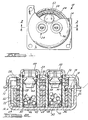
Figure 1 is a cross-sectional top view of a two-chamber inflator in accordance with the present invention. -
Figure 2 is a cross-sectional view taken along the line 2-2 ofFigure 1 . - As seen in the figures, an inflator 10, in accordance with a preferred embodiment of the present invention, contains a
housing 12 formed from abase 14 welded or otherwise fixed to acap 16. Adivider disc 18 divides thehousing 12 into aprimary chamber 22 and asecondary chamber 20, whereby thechamber 20 is formed within thebase 14 and thechamber 22 is formed within thecap 16. - The
base 14,cap 16, anddivider disc 18 are preferably formed from stamped steel, or by other known and accepted methods and materials. Thebase 14 contains afirst annulus 24 and asecond annulus 26. Thedivider disc 18 contains a third annulus 28 and afourth annulus 30, each in corresponding axial alignment withfirst annulus 24 andsecond annulus 26, respectively. - As shown in the Figures, a
first igniter chamber 32 is formed when afirst igniter tube 34 is inserted through and welded to the first andthird annuli 24 and 28, respectively, whereintube 34 andannuli 24 and 28 are substantially equal in circumference. Similarly, asecond igniter chamber 36 is formed when a second igniter tube 38 is inserted through and welded to the second andfourth annuli annuli -
Chamber 32 contains aproximate end 40 and adistal end 42. A first igniter 44 is inserted through theproximate end 40 and is thereby disposed withinignition chamber 32. Igniter 44 is then preferably crimped to tube 34. At least onegas exit aperture 46 extends throughdistal end 42 thereby facilitating fluid communication betweenchamber 32 and a primary gasgenerant propellant 48 within the primarygas generant chamber 22. -
Chamber 36 contains aproximate end 50 and adistal end 52. Asecond igniter 54 is inserted through theproximate end 50 and is thereby disposed withinchamber 36. Igniter 54 is then preferably crimped to second tube 38. At least one second gas exit aperture 56 extends throughproximate end 50 thereby facilitating fluid communication betweenignition chamber 36 and a secondary primary gasgenerant propellant 58 within the secondary gasgenerant chamber 20. - An
annular filter 64 is peripherally and radially spaced from an axis extending throughchambers gas exit apertures 66 are circumferentially and homolaterally disposed within thehousing 12 and about the primarygas generant chamber 22, thereby providing fluid communication between thechamber 22 and an airbag (not shown). In a preferred embodiment, foil covers each aperture in the second plurality ofapertures 66, thereby sealingchamber 22. - As shown in the figures, the
disc 18 is welded totubes 34 and 38 and to thecap 16. Thetubes 34 and 38 are also welded to thecap 16 thereby enhancing structural integrity. - A
first initiator composition 68 is provided within thefirst ignition chamber 32. Asecond initiator composition 70, the same as or different fromcomposition 68, is provided within thesecond chamber 36. - In operation, a vehicle occupant protection system generates a signal indicating sudden deceleration or a crash event that is then sensed by igniter 44 thereby triggering ignition of the
first initiator propellant 68. Upon ignition ofcomposition 68, the heat, flame, and combustion gases produced flow into the primarygas generant chamber 22 thereby igniting the primarygas generant propellant 48. The resultant gases then flow fromchamber 22 throughfilter 64 and outapertures 66 into an airbag (not shown). - The
second chamber 20 is selectively operated based on factors such as crash severity, occupant position sensing, and the weight and/or height of the occupant. Thedivider disc 18 contains at least one aperture and preferably a first plurality ofgas exit apertures 60 for transfer of secondary gas fromchamber 20 intochamber 22. A first burst shim (e. g. steel or aluminum) 62 covers the plurality ofapertures 60 on an upper or first disc surface 57 thereby sealingchamber 20 and facilitating a sufficient increase in combustion pressure when thesecond chamber 20 is activated. A seal 61, such as sealing tape, is preferably fixed to a lower or second disc surface 59 thereby preventing flame front and hot gases from migrating from thelower chamber 22 into theupper chamber 20. As such, given a lower weight occupant,chamber 22 may be selected to singularly operate without simultaneous operation ofchamber 20. - On the other hand, given a heavier occupant,
chambers chambers propellant 58 overcomes the burst shim 62 as gas passes through the aperture(s) 60 breaking the integrity of the seal 61. As such, gas produced fromchambers chamber 22 as they exit thegas exit apertures 66. -
- When compared to other inflators known in the art, the present inflator enhances the safety of the occupant by ensuring discrete operation of
chambers chamber 22 be selected, the present design facilitates the activation ofchamber 20 after about 15-20 seconds. However, there is no likelihood of redeploying the airbag and injuring an out-of-position occupant becausechamber 22 contains a primary charge representing at least 70-80% of the total gas generant charge between the two chambers. Therefore, whenchamber 20 is conductively or passively activated, there is only 20-30% of the overall propellant charge acting on the airbag. Stated another way,chamber 20 merely augments the primary gas force provided bychamber 22 upon activation.Chamber 20 would not singularly provide enough gas generation to effect the airbag inflation necessary to adequately protect the occupant, and therefore, it is only actively operated to work in conjunction withchamber 22. - It will be understood that the foregoing description of the preferred embodiment of the present invention is for illustrative purposes only. As such, the various structural and operational features herein disclosed are susceptible to a number of modifications commensurate with the abilities of one of ordinary skill in the art, none of which departs from the scope of the present invention as defined in the appended claims.
Claims (1)
- A dual chamber inflator (10) for a vehicle occupant protection system comprising:a housing (12) comprising a base (14) and a cap (16), said cap (16) further comprising a first plurality of gas exit apertures (66) peripherally spaced therein;a divider (18) for forming a first propellant chamber (22) and a second propellant chamber (20) within said housing (12), said chambers (20, 22) operatively separated from each other, and, said divider (18) comprising a top surface (57), a bottom surface (59), and at least one aperture (60) providing fluid communication from the second propellant chamber (20) to the first propellant chamber (22);a first gas generating propellant (48) contained within said first chamber (22), said first propellant (48) combusted upon activation of said inflator;a second gas generating propellant (58) contained within said second chamber (20), said second propellant (58) optionally combusted simultaneously with said first propellant (48); anda seal (61) fixed over said at least one aperture (60) on said bottom surface (59) thereby preventing simultaneous operation of said first chamber (22) and said second chamber (20) when only said first chamber (22) is activated upon a crash event,characterized in that:and in thatthe divider (18) is a planar divider disc (18) intermediate of said base (14) and said cap (16) such that the first propellant chamber (22) and second propellant chamber (20) are formed within said cap (16) and said base (14), respectively,
said first plurality of gas exit apertures (66) are circumferentially and homolaterally disposed within the housing (12) and about said first propellant chamber (22), thereby providing fluid communication between said first propellant chamber (22) and an airbag.
Applications Claiming Priority (3)
| Application Number | Priority Date | Filing Date | Title |
|---|---|---|---|
| US26454801P | 2001-01-26 | 2001-01-26 | |
| US264548P | 2001-01-26 | ||
| PCT/US2002/002399 WO2002058971A1 (en) | 2001-01-26 | 2002-01-28 | Dual chamber inflator |
Publications (3)
| Publication Number | Publication Date |
|---|---|
| EP1361971A1 EP1361971A1 (en) | 2003-11-19 |
| EP1361971A4 EP1361971A4 (en) | 2005-02-09 |
| EP1361971B1 true EP1361971B1 (en) | 2008-02-27 |
Family
ID=23006539
Family Applications (1)
| Application Number | Title | Priority Date | Filing Date |
|---|---|---|---|
| EP02706024A Expired - Lifetime EP1361971B1 (en) | 2001-01-26 | 2002-01-28 | Dual chamber inflator |
Country Status (5)
| Country | Link |
|---|---|
| US (1) | US6764096B2 (en) |
| EP (1) | EP1361971B1 (en) |
| JP (1) | JP3830897B2 (en) |
| DE (1) | DE60225248T2 (en) |
| WO (1) | WO2002058971A1 (en) |
Families Citing this family (30)
| Publication number | Priority date | Publication date | Assignee | Title |
|---|---|---|---|---|
| DE20219899U1 (en) * | 2002-12-23 | 2003-05-28 | TRW Airbag Systems GmbH, 84544 Aschau | inflator |
| US6886856B2 (en) * | 2003-04-01 | 2005-05-03 | Key Safety Systems, Inc. | Dual stage inflator |
| US7401810B2 (en) * | 2003-07-07 | 2008-07-22 | Autoliv Asp, Inc. | Ultrasonic welded initiator and connector socket |
| US6983956B2 (en) * | 2003-08-14 | 2006-01-10 | Key Safety Systems, Inc. | Dual stage pyrotechnic inflator |
| US7017944B2 (en) * | 2004-01-16 | 2006-03-28 | Automotive Systems Laboratory, Inc. | Multiple chamber inflator |
| US20050161135A1 (en) * | 2004-01-28 | 2005-07-28 | Williams Graylon K. | Auto-igniting pyrotechnic booster composition |
| US7267365B2 (en) * | 2004-03-10 | 2007-09-11 | Automotive Systems Laboratory, Inc. | Inflator |
| US7367584B2 (en) * | 2004-04-19 | 2008-05-06 | Automotive Systems Laboratory, Inc. | Gas generating system |
| FR2870234B1 (en) * | 2004-05-13 | 2007-02-09 | Snpe Materiaux Energetiques Sa | DOSABLE PYROTECHNIC COMPOSITION USED AS A THERMAL FUSE IN A GAS GENERATOR AND A GAS GENERATOR INCLUDING A COMPOUND HAVING THE SAME |
| US7343862B2 (en) * | 2004-05-27 | 2008-03-18 | Automotive Systems Laboratory, Inc. | Gas generating system |
| US7438315B2 (en) * | 2004-05-28 | 2008-10-21 | Automotive Systems Laboratory, Inc. | Inflator and method of assembly |
| US7814838B2 (en) * | 2004-06-28 | 2010-10-19 | Automotive Systems, Laboratory, Inc. | Gas generating system |
| US7237801B2 (en) * | 2004-08-31 | 2007-07-03 | Automotive Systems Laboratory, Inc. | Gas generating system |
| US7347448B2 (en) * | 2004-10-19 | 2008-03-25 | Autoliv Asp, Inc. | Inflator device for airbag installations |
| US7537240B2 (en) * | 2005-02-22 | 2009-05-26 | Automotive Systems Laboratory, Inc. | Gas generating system |
| US7654565B2 (en) * | 2005-06-02 | 2010-02-02 | Automotive Systems Laboratory, Inc. | Gas generating system |
| WO2007005824A2 (en) | 2005-06-30 | 2007-01-11 | Automotive Systems Laboratory, Inc. | Gas generator |
| US20070047228A1 (en) * | 2005-08-27 | 2007-03-01 | 3M Innovative Properties Company | Methods of forming direct-lit backlights having light recycling cavity with concave transflector |
| US7815355B2 (en) * | 2005-08-27 | 2010-10-19 | 3M Innovative Properties Company | Direct-lit backlight having light recycling cavity with concave transflector |
| US7695180B2 (en) * | 2005-08-27 | 2010-04-13 | 3M Innovative Properties Company | Illumination assembly and system |
| US7537374B2 (en) * | 2005-08-27 | 2009-05-26 | 3M Innovative Properties Company | Edge-lit backlight having light recycling cavity with concave transflector |
| US20070085314A1 (en) * | 2005-10-14 | 2007-04-19 | Daicel Chemical Industries, Ltd. | Gas generator for airbag |
| US7950691B1 (en) | 2007-10-31 | 2011-05-31 | Tk Holdings, Inc. | Inflator body with adapter form end |
| US7950693B2 (en) * | 2008-05-20 | 2011-05-31 | Autoliv Asp, Inc. | Dual stage inflator |
| US8282127B1 (en) | 2008-09-03 | 2012-10-09 | Tk Holdings, Inc. | Gas generating system |
| US8172262B2 (en) * | 2008-11-13 | 2012-05-08 | Tk Holdings, Inc. | Initiator housing assembly |
| US8047569B2 (en) * | 2010-03-12 | 2011-11-01 | Autoliv Asp, Inc. | Multi-stage inflator |
| DE202010014286U1 (en) * | 2010-10-15 | 2012-01-30 | Trw Airbag Systems Gmbh | Gas generator and gas bag module |
| US8556294B1 (en) | 2012-08-22 | 2013-10-15 | Key Safety Systems, Inc | Airbag inflator |
| JP7306902B2 (en) | 2019-07-12 | 2023-07-11 | 株式会社ダイセル | gas generator |
Family Cites Families (13)
| Publication number | Priority date | Publication date | Assignee | Title |
|---|---|---|---|---|
| US5513879A (en) * | 1994-05-04 | 1996-05-07 | Breed Automotive Technology, Inc. | Two stage inflator with module venting for passenger side airbags |
| FR2763548B1 (en) * | 1997-05-23 | 1999-06-18 | Livbag Snc | PYROTECHNIC ADAPTIVE GAS GENERATOR WITH TUBULAR CHAMBERS FOR PROTECTIVE CUSHION |
| US6032979C1 (en) * | 1998-02-18 | 2001-10-16 | Autoliv Asp Inc | Adaptive output inflator |
| DE19834690A1 (en) | 1998-07-31 | 2000-02-03 | Takata Europ Gmbh | Airbag device with gas generator |
| ATE258124T1 (en) * | 1998-09-28 | 2004-02-15 | Daicel Chem | AIR BAG GAS GENERATOR AND AIR BAG SYSTEM |
| JP3781603B2 (en) * | 1999-02-05 | 2006-05-31 | 日本化薬株式会社 | Gas generator |
| EP1155927B1 (en) * | 1999-02-05 | 2006-03-29 | Nippon Kayaku Kabushiki Kaisha | Gas generator |
| US6227565B1 (en) * | 1999-03-04 | 2001-05-08 | Trw Inc. | Air bag inflator with pressure regulation |
| US6315322B1 (en) | 1999-03-05 | 2001-11-13 | Trw Inc. | Air bag inflator |
| US6199906B1 (en) * | 1999-08-12 | 2001-03-13 | Breed Automotive Technology, Inc. | Dual stage pyrotechnic inflator |
| US6189927B1 (en) * | 1999-12-16 | 2001-02-20 | Autoliv Asp, Inc. | Adaptive output inflator |
| WO2001047752A1 (en) * | 1999-12-28 | 2001-07-05 | Nippon Koki Co., Ltd. | Dual inflator |
| JP4631189B2 (en) * | 2001-03-21 | 2011-02-16 | タカタ株式会社 | Gas generator |
-
2002
- 2002-01-28 JP JP2002559282A patent/JP3830897B2/en not_active Expired - Fee Related
- 2002-01-28 EP EP02706024A patent/EP1361971B1/en not_active Expired - Lifetime
- 2002-01-28 WO PCT/US2002/002399 patent/WO2002058971A1/en not_active Ceased
- 2002-01-28 US US10/058,866 patent/US6764096B2/en not_active Expired - Lifetime
- 2002-01-28 DE DE60225248T patent/DE60225248T2/en not_active Expired - Lifetime
Also Published As
| Publication number | Publication date |
|---|---|
| EP1361971A4 (en) | 2005-02-09 |
| DE60225248T2 (en) | 2009-03-12 |
| JP3830897B2 (en) | 2006-10-11 |
| US6764096B2 (en) | 2004-07-20 |
| DE60225248D1 (en) | 2008-04-10 |
| EP1361971A1 (en) | 2003-11-19 |
| WO2002058971A1 (en) | 2002-08-01 |
| JP2004520997A (en) | 2004-07-15 |
| WO2002058971A9 (en) | 2003-06-05 |
| US20020101068A1 (en) | 2002-08-01 |
Similar Documents
| Publication | Publication Date | Title |
|---|---|---|
| EP1361971B1 (en) | Dual chamber inflator | |
| US6659500B2 (en) | Multi-chamber inflator | |
| US6422601B1 (en) | Dual chamber inflator | |
| US7950693B2 (en) | Dual stage inflator | |
| CA2226364C (en) | Dual chamber nonazide gas generator | |
| JP4814082B2 (en) | Gunpowder inflator for automotive airbag systems | |
| JP2004520997A6 (en) | 2-chamber inflator | |
| EP1152929B1 (en) | Two chamber gas generator | |
| WO1999042339A1 (en) | Adaptive output inflator | |
| US6860511B2 (en) | Multiple chamber dual stage inflator | |
| US6997477B2 (en) | Inflator | |
| US7017944B2 (en) | Multiple chamber inflator | |
| EP1174313B1 (en) | Multi-chamber inflator |
Legal Events
| Date | Code | Title | Description |
|---|---|---|---|
| PUAI | Public reference made under article 153(3) epc to a published international application that has entered the european phase |
Free format text: ORIGINAL CODE: 0009012 |
|
| 17P | Request for examination filed |
Effective date: 20030728 |
|
| AK | Designated contracting states |
Kind code of ref document: A1 Designated state(s): AT BE CH CY DE DK ES FI FR GB GR IE IT LI LU MC NL PT SE TR |
|
| A4 | Supplementary search report drawn up and despatched |
Effective date: 20041223 |
|
| 17Q | First examination report despatched |
Effective date: 20050704 |
|
| 17Q | First examination report despatched |
Effective date: 20050704 |
|
| GRAP | Despatch of communication of intention to grant a patent |
Free format text: ORIGINAL CODE: EPIDOSNIGR1 |
|
| GRAS | Grant fee paid |
Free format text: ORIGINAL CODE: EPIDOSNIGR3 |
|
| GRAA | (expected) grant |
Free format text: ORIGINAL CODE: 0009210 |
|
| AK | Designated contracting states |
Kind code of ref document: B1 Designated state(s): DE GB |
|
| RBV | Designated contracting states (corrected) |
Designated state(s): DE GB |
|
| REG | Reference to a national code |
Ref country code: GB Ref legal event code: FG4D |
|
| REF | Corresponds to: |
Ref document number: 60225248 Country of ref document: DE Date of ref document: 20080410 Kind code of ref document: P |
|
| PLBE | No opposition filed within time limit |
Free format text: ORIGINAL CODE: 0009261 |
|
| STAA | Information on the status of an ep patent application or granted ep patent |
Free format text: STATUS: NO OPPOSITION FILED WITHIN TIME LIMIT |
|
| 26N | No opposition filed |
Effective date: 20081128 |
|
| GBPC | Gb: european patent ceased through non-payment of renewal fee |
Effective date: 20090128 |
|
| PG25 | Lapsed in a contracting state [announced via postgrant information from national office to epo] |
Ref country code: GB Free format text: LAPSE BECAUSE OF NON-PAYMENT OF DUE FEES Effective date: 20090128 |
|
| PGFP | Annual fee paid to national office [announced via postgrant information from national office to epo] |
Ref country code: DE Payment date: 20150120 Year of fee payment: 14 |
|
| REG | Reference to a national code |
Ref country code: DE Ref legal event code: R119 Ref document number: 60225248 Country of ref document: DE |
|
| PG25 | Lapsed in a contracting state [announced via postgrant information from national office to epo] |
Ref country code: DE Free format text: LAPSE BECAUSE OF NON-PAYMENT OF DUE FEES Effective date: 20160802 |