KR101292233B1 - Waste treating system - Google Patents
Waste treating system Download PDFInfo
- Publication number
- KR101292233B1 KR101292233B1 KR1020110009230A KR20110009230A KR101292233B1 KR 101292233 B1 KR101292233 B1 KR 101292233B1 KR 1020110009230 A KR1020110009230 A KR 1020110009230A KR 20110009230 A KR20110009230 A KR 20110009230A KR 101292233 B1 KR101292233 B1 KR 101292233B1
- Authority
- KR
- South Korea
- Prior art keywords
- combustion
- furnace
- exhaust gas
- heat
- temperature
- Prior art date
Links
Images


Classifications
-
- F—MECHANICAL ENGINEERING; LIGHTING; HEATING; WEAPONS; BLASTING
- F23—COMBUSTION APPARATUS; COMBUSTION PROCESSES
- F23G—CREMATION FURNACES; CONSUMING WASTE PRODUCTS BY COMBUSTION
- F23G5/00—Incineration of waste; Incinerator constructions; Details, accessories or control therefor
- F23G5/02—Incineration of waste; Incinerator constructions; Details, accessories or control therefor with pretreatment
- F23G5/027—Incineration of waste; Incinerator constructions; Details, accessories or control therefor with pretreatment pyrolising or gasifying stage
-
- C—CHEMISTRY; METALLURGY
- C02—TREATMENT OF WATER, WASTE WATER, SEWAGE, OR SLUDGE
- C02F—TREATMENT OF WATER, WASTE WATER, SEWAGE, OR SLUDGE
- C02F11/00—Treatment of sludge; Devices therefor
- C02F11/10—Treatment of sludge; Devices therefor by pyrolysis
-
- F—MECHANICAL ENGINEERING; LIGHTING; HEATING; WEAPONS; BLASTING
- F23—COMBUSTION APPARATUS; COMBUSTION PROCESSES
- F23J—REMOVAL OR TREATMENT OF COMBUSTION PRODUCTS OR COMBUSTION RESIDUES; FLUES
- F23J11/00—Devices for conducting smoke or fumes, e.g. flues
-
- F—MECHANICAL ENGINEERING; LIGHTING; HEATING; WEAPONS; BLASTING
- F23—COMBUSTION APPARATUS; COMBUSTION PROCESSES
- F23J—REMOVAL OR TREATMENT OF COMBUSTION PRODUCTS OR COMBUSTION RESIDUES; FLUES
- F23J3/00—Removing solid residues from passages or chambers beyond the fire, e.g. from flues by soot blowers
- F23J3/04—Traps
-
- Y—GENERAL TAGGING OF NEW TECHNOLOGICAL DEVELOPMENTS; GENERAL TAGGING OF CROSS-SECTIONAL TECHNOLOGIES SPANNING OVER SEVERAL SECTIONS OF THE IPC; TECHNICAL SUBJECTS COVERED BY FORMER USPC CROSS-REFERENCE ART COLLECTIONS [XRACs] AND DIGESTS
- Y02—TECHNOLOGIES OR APPLICATIONS FOR MITIGATION OR ADAPTATION AGAINST CLIMATE CHANGE
- Y02W—CLIMATE CHANGE MITIGATION TECHNOLOGIES RELATED TO WASTEWATER TREATMENT OR WASTE MANAGEMENT
- Y02W10/00—Technologies for wastewater treatment
- Y02W10/40—Valorisation of by-products of wastewater, sewage or sludge processing
Abstract
아산화질소의 발생을 억제할 수 있는 폐기물 처리 시스템을 제공할 수 있다. 폐기물 처리 시스템은, 유기성 폐기물을 열 분해하는 열 분해로와, 열 분해로에서 발생한 가연성의 열 분해 가스를 연소시키는 연소로와, 연소로에서 발생한 연소 배기 가스를 열원으로서 이용하는 열 이용 기기와, 열 이용 기기에 의해 이용되어 온도가 저하한 연소 배기 가스를, 연소 공기로서 연소로에 환류시켜 환류 라인을 갖는다.The waste disposal system which can suppress generation | occurrence | production of nitrous oxide can be provided. The waste treatment system includes a pyrolysis furnace for pyrolyzing organic waste, a combustion furnace for combusting flammable pyrolysis gas generated in the pyrolysis furnace, a heat utilization device using a combustion exhaust gas generated in the combustion furnace as a heat source, and heat The combustion exhaust gas used by the utilization apparatus and the temperature fell is refluxed as combustion air to a combustion furnace, and has a reflux line.
Description
본 발명의 실시예는 유기성(有機性) 폐기물을 처리하는 폐기물 처리 시스템에 관한 것이다.Embodiments of the present invention relate to a waste treatment system for treating organic waste.
탈수 오니(汚泥) 등의 유기성 폐기물을 처리하는 폐기물 처리 시스템은, 유기성 폐기물을 열 분해로 내에 있어서 저(低)산소 상태에서 가열 분해하여, 유기성 폐기물을 열 분해 가스와 열 분해 잔사로 분리한다. 또한 폐기물 처리 시스템은, 가연성의 열 분해 가스를 연소로에서 연소시켜서, 이 연소 배기 가스를 열 이용 기기의 열원으로 하고 있다. 연소 배기 가스는, 열 이용 기기에 있어서 열 에너지를 빼앗겨 온도가 강하해서, 저온 연소 배기 가스로서 배출된다.In a waste treatment system for treating organic waste such as dewatered sludge, the organic waste is thermally decomposed in a low oxygen state in a pyrolysis furnace, and the organic waste is separated into a pyrolysis gas and a pyrolysis residue. In addition, the waste treatment system combusts flammable pyrolysis gas in a combustion furnace, and uses this combustion exhaust gas as a heat source of a heat utilization device. The combustion exhaust gas loses heat energy in the heat utilization device, and the temperature drops, and the combustion exhaust gas is discharged as the low temperature combustion exhaust gas.
일본 특허 제4198426호 공보 및 일본특허출원 공개 제2007-270018호 공보에 기재되어 있는 종래의 폐기물 처리 시스템은, 유기성 폐기물에 유기 질소가 포함될 경우, 온실효과 가스인 아산화질소(N2O)를 생성한다. 아산화질소는, 지구 환경에 악영향을 끼치는 물질, 소위 환경 부하를 증가시키는 물질이므로, 그 배출량을 가능한 한 억제하지 않으면 안된다.Conventional waste treatment systems described in Japanese Patent No. 4198426 and Japanese Patent Application Laid-Open No. 2007-270018 produce nitrous oxide (N 2 O), which is a greenhouse gas when organic nitrogen is included in organic waste. do. Nitrous oxide is a substance which adversely affects the global environment, and a substance which increases so-called environmental load. Therefore, the emission must be restrained as much as possible.
본 발명이 해결하고자 과제는, 아산화질소의 발생을 억제할 수 있는 폐기물 처리 시스템을 제공하는 것이다.An object of the present invention is to provide a waste treatment system capable of suppressing the generation of nitrous oxide.
실시예의 폐기물 처리 시스템은, 유기성 폐기물을 받아들여 고온의 환원성 분위기 하에서 상기 유기성 폐기물을 열 분해시키는 열 분해로와, 상기 열 분해로에서 발생한 가연성의 열 분해 가스를 연소시키는 연소로와, 상기 연소로에서 발생한 연소 배기 가스를 열원으로서 이용하는 1개 또는 복수의 열 이용 기기와, 상기 열 이용 기기에 의해 이용되어 온도가 저하한 열 이용 후의 저온 배기 가스를, 상기 열 이용 기기로부터 상기 열 이용 기기보다 상류측에 배치된 기기에 환류시켜, 상기 상류측에 배치된 기기에 있어서 연소 공기 또는 희석 공기로서 이용시키는 환류 라인을 구비하는 것을 특징으로 한다.The waste treatment system of the embodiment includes a pyrolysis furnace that receives organic waste and thermally decomposes the organic waste in a high-temperature reducing atmosphere, a combustion furnace that combusts flammable pyrolysis gas generated in the pyrolysis furnace, and the combustion furnace One or a plurality of heat using apparatuses using combustion exhaust gas generated as a heat source and low-temperature exhaust gas after heat use, which is used by the heat using apparatuses and whose temperature has decreased, upstream from the heat using apparatuses. And a reflux line for reflux to the apparatus arranged on the side, and used as combustion air or dilution air in the apparatus arranged on the upstream side.
상기 구성의 폐기물 처리 시스템에 의하면, 아산화질소의 발생을 억제할 수 있다.According to the waste processing system of the said structure, generation | occurrence | production of nitrous oxide can be suppressed.
도 1은 제 1 실시예에 따른 폐기물 처리 시스템을 나타낸 구성 블록도.
도 2는 연소로의 연소 온도와 저온 연소 배기 가스 중의 N2O 농도의 관계를 나타낸 도면.
도 3은 제 2 실시예에 따른 폐기물 처리 시스템을 나타낸 구성 블록도.
도 4는 제 3 실시예에 따른 폐기물 처리 시스템을 나타낸 구성 블록도.1 is a block diagram showing a waste treatment system according to a first embodiment;
2 is a diagram showing a relationship between a combustion temperature of a combustion furnace and N 2 O concentration in a low temperature combustion exhaust gas;
3 is a block diagram showing a waste treatment system according to a second embodiment;
4 is a block diagram illustrating a waste treatment system according to a third embodiment;
실시예의 폐기물 처리 시스템은, 고온의 환원성 분위기 하에서 유기성 폐기물을 열 분해하는 열 분해로와, 열 분해로에서 발생한 가연성의 열 분해 가스를 연소하는 연소로와, 연소로에서 발생한 연소 배기 가스를 열원으로서 이용하는 열 이용 기기와, 열 이용 기기에 의해 열이 이용되어 온도가 저하한 열 이용 후의 저온 배기 가스를, 연소 공기로서 연소로에 환류시키는 환류 라인을 갖는다.The waste treatment system of the embodiment includes a thermal decomposition furnace for thermally decomposing organic waste in a high-temperature reducing atmosphere, a combustion furnace for combusting flammable pyrolysis gas generated in the thermal decomposition furnace, and combustion exhaust gas generated in the combustion furnace as heat sources. And a reflux line for refluxing the low-temperature exhaust gas after heat use, in which heat is used by the heat-use device and the temperature is lowered, as combustion air.
실시예에서는, 열 이용 후의 저온 배기 가스를 환류 라인에 의해 연소로에 환류시켜, 연소로에 있어서 저온 배기 가스를 연소 공기의 일부로서 이용한다. 저온 배기 가스를 연소 공기의 일부로서 이용하면, 상온의 외기(外氣)만을 연소 공기로서 이용할 경우와 비교해서 배기 가스량으로 연소로의 연소 온도를 상승시킬 수 있다. 연소로의 연소 온도가 상승하면, 연소 배기 가스 중의 아산화질소의 생성량이 감소한다. 열 이용 후의 연소 배기 가스는 외기에 비해 훨씬 고온이기 때문에, 연소로의 연소 공기로서 이용되는 것에 적합하며, 폐기물 처리 시스템 전체의 열 이용 효율을 향상시키는데 크게 기여할 수 있다.In the embodiment, the low temperature exhaust gas after heat use is refluxed to the combustion furnace by the reflux line, and the low temperature exhaust gas is used as part of the combustion air in the combustion furnace. When the low-temperature exhaust gas is used as part of the combustion air, the combustion temperature of the combustion furnace can be increased by the amount of the exhaust gas as compared with the case where only external air at ordinary temperature is used as the combustion air. As the combustion temperature in the combustion furnace rises, the amount of nitrous oxide produced in the combustion exhaust gas decreases. Since the combustion exhaust gas after heat use is much higher than outside air, it is suitable for being used as combustion air in a combustion furnace, and can greatly contribute to improving the heat utilization efficiency of the entire waste treatment system.
또한, 저온 배기 가스를 연소로로부터 배출되는 연소 배기 가스의 희석 공기로서 사용하면, 연소 후의 연소 배기 가스의 온도를 내릴 수 있다. 이 때문에, 열 이용 기기의 재질 등의 이유 때문에 연소 배기 가스의 온도에 상한이 있어도, 열 이용 기기에 도입되는 연소 배기 가스의 온도를 내릴 수 있다. 열 이용 후의 연소 배기 가스를 희석 공기로서 사용하면, 외기를 희석 공기로서 사용할 경우에 비해, 시스템 외부로 배출되는 배기 가스량을 적게 할 수 있다. 또한, 이에 따라 폐기물 처리 시스템 전체의 열 이용 효율이 향상된다.When the low-temperature exhaust gas is used as dilution air of the combustion exhaust gas discharged from the combustion furnace, the temperature of the combustion exhaust gas after combustion can be lowered. For this reason, even if there is an upper limit to the temperature of the combustion exhaust gas for reasons such as the material of the heat utilization apparatus, the temperature of the combustion exhaust gas introduced into the heat utilization apparatus can be lowered. When the combustion exhaust gas after heat use is used as dilution air, the amount of exhaust gas discharged | emitted out of a system can be reduced compared with the case where external air is used as dilution air. In addition, the heat utilization efficiency of the entire waste treatment system is improved.
실시예의 폐기물 처리 시스템에서는, 연소로가 열 분해 가스를 900℃ 이상 1000℃ 이하의 온도 범위에서 연소시킴으로써, 아산화질소의 발생을 억제하는 것이 바람직하다. 연소 배기 가스 중의 N2O 농도는, 연소로의 연소 온도가 높아짐에 따라 감소해 가지만, 연소 온도가 900℃ 이상이 되면 거의 일정해진다. 예를 들면 연소 온도가 870℃일 때의 연소 배기 가스 중의 N2O 농도와 900℃일 때의 연소 배기 가스 중의 N2O 농도를 비교하면, 온도차는 불과 30℃임에도 불구하고, 후자의 N2O 농도는 전자의 N2O 농도의 거의 절반으로 급격하게 저하된다(도 2를 참조). 더 연소 온도를 상승시켜가서 950℃ 이상으로 하면, 연소 배기 가스 중의 N2O 농도는 거의 변화되지 않게 되어 실질적으로 일정하게 된다(도 2를 참조). 이 때문에, 실시예에서는, 더 바람직하게는 연소로의 연소 온도가 950℃ 이상이 되도록 열 분해 가스를 연소시킨다.In the waste disposal system of an Example, it is preferable that a combustion furnace suppresses generation | occurrence | production of nitrous oxide by burning a pyrolysis gas in the temperature range of 900 degreeC or more and 1000 degrees C or less. The N 2 O concentration in the combustion exhaust gas decreases as the combustion temperature of the combustion furnace increases, but becomes nearly constant when the combustion temperature reaches 900 ° C or more. For example, comparing the N 2 O concentration in the combustion exhaust gas when the combustion temperature is 870 ° C. and the N 2 O concentration in the combustion exhaust gas when the
한편, 연소로의 설계 온도는 1200℃로, 연소로를 구성하는 재료와 구조는 그 온도까지 견딜 수 있도록 설계되어 있다. 그러나, 연소로의 수명을 연장시키기 위함 등의 이유 때문에, 연소로가 운전될 때의 실제의 연소 온도는 최고로 약 1000℃까지이다. 이 때문에, 실시예에서는, 연소로의 연소 온도의 상한값을 1000℃로 한다.On the other hand, the design temperature of a combustion furnace is 1200 degreeC, and the material and structure which comprise a combustion furnace are designed to withstand the temperature. However, for reasons such as to prolong the life of the furnace, the actual combustion temperature when the furnace is operated is at most up to about 1000 ° C. For this reason, in an Example, the upper limit of the combustion temperature of a combustion furnace shall be 1000 degreeC.
실시예의 폐기물 처리 시스템은, 열 분해로보다 상류측에 배치되는 유기성 폐기물의 함유 수분을 감소시키는 건조기를 더 갖는 것이 바람직하다. 건조기는, 유기성 폐기물을 가열하여 유기성 폐기물로부터 수분을 증발시켜, 유기성 폐기물의 함유 수분을 감소시킨다.It is preferable that the waste processing system of the Example further has a dryer which reduces the moisture content of organic waste arrange | positioned upstream rather than a thermal decomposition furnace. The dryer heats the organic waste to evaporate moisture from the organic waste, thereby reducing the moisture contained in the organic waste.
건조기를 이용하여 유기성 폐기물을 가열 건조시켜, 유기성 폐기물의 함유 수분을 감소시키면, 열 분해로에 있어서 유기성 폐기물의 열 분해 반응이 신속하고, 또한 원활하게 진행된다고 하는 장점이 있다. 유기성 폐기물로서 활성 오니와 같은 수분을 다량으로 포함하는 것을 처리할 경우, 이것을 열 분해로에 직송하면, 가열되는 유기성 폐기물의 중량이 크기 때문에 열 분해로의 부하가 증대된다. 유기성 폐기물을 건조기에서 미리 건조해서 중량을 작게 하면, 열 분해로의 부하가 경감된다.When the organic waste is heat-dried using a dryer to reduce the moisture content of the organic waste, there is an advantage that the thermal decomposition reaction of the organic waste proceeds quickly and smoothly in the thermal cracking furnace. In the case where a large amount of water such as activated sludge is treated as an organic waste, if it is sent directly to a pyrolysis furnace, the load of the pyrolysis furnace is increased because the weight of the organic waste to be heated is large. When the organic waste is dried in a dryer in advance and the weight is reduced, the load on the thermal decomposition furnace is reduced.
이 건조기는, 열 이용 기기에서 열이 이용된 후의 저온 연소 배기 가스가 보유하는 열을 이용하는 상류측에 배치되는 기기의 하나로 될 수 있다. 즉, 열을 이용한 후의 저온 연소 배기 가스를 환류 라인을 통해 연소로의 상류측의 건조기에 공급한다. 이에 따라, 건조기가 저온 연소 배기 가스를 이용할 수 있다. 열 이용 기기로부터 배출되는 저온 연소 배기 가스의 온도는 500℃ 이하이고, 또한 건조기의 프로세스 설계 온도는 100℃ ~ 300℃의 범위이다. 건조기는 다양한 열원을 이용할 수 있고, 저온 연소 배기 가스 이외에, 열매(熱媒)나 전기 저항 가열 장치, 연소 가열 장치 등의 공지의 범용 가열 장치를 이용할 수 있다.This dryer can be one of the apparatus arrange | positioned upstream using the heat which the low temperature combustion exhaust gas after heat is used by a heat utilization apparatus uses. That is, the low temperature combustion exhaust gas after using heat is supplied to the dryer upstream of a combustion furnace via a reflux line. As a result, the dryer can use low-temperature combustion exhaust gas. The temperature of the low temperature combustion exhaust gas discharged from the heat utilizing apparatus is 500 degrees C or less, and the process design temperature of a dryer is 100 degreeC-300 degreeC. The dryer can use various heat sources, and can use well-known general-purpose heating apparatuses, such as a heat exchanger, an electric resistance heating apparatus, and a combustion heating apparatus, in addition to low temperature combustion exhaust gas.
또한 열 이용 후의 저온 연소 배기 가스를, 연소로의 하류측에 배치된 열 이용 기기로부터 환류 라인을 통해 연소로의 상류측의 열 분해로에 공급한다. 이에 따라, 열 분해로가 저온 연소 배기 가스를 이용할 수 있다. 열 분해로의 프로세스 설계 온도는 300℃ ~ 750℃의 범위이다.Moreover, the low temperature combustion exhaust gas after heat use is supplied to the thermal decomposition furnace upstream of a combustion furnace through the reflux line from the heat utilization apparatus arrange | positioned downstream of a combustion furnace. Accordingly, the pyrolysis furnace can use low temperature combustion exhaust gas. Process design temperatures for pyrolysis furnaces range from 300 ° C to 750 ° C.
폐기물 처리 시스템은, 열 이용 기기와 연소로 사이에 집진기를 더 갖는 것이 바람직하다(도 3을 참조).It is preferable that a waste processing system further has a dust collector between a heat utilization apparatus and a combustion furnace (refer FIG. 3).
연소로에서 발생하는 고형분인 매진(煤塵)은, 열 이용 기기의 내벽에 부착되어 열 이용 효율을 저하시킨다. 이 때문에, 집진기를 이용하여 연소 배기 가스로부터 매진을 분리 제거함으로써, 열 이용 기기의 열 이용 효율의 저하를 방지할 수 있다. 또한, 본 발명에 있어서, 집진기는 특정한 형식에만 한정되지 않는다.Sold out, which is a solid content generated in the combustion furnace, adheres to the inner wall of the heat-use device, thereby lowering the heat-use efficiency. For this reason, it is possible to prevent the deterioration of the heat utilization efficiency of the heat using apparatus by separating and removing the dust from the combustion exhaust gas using the dust collector. In addition, in this invention, a dust collector is not limited only to a specific type.
폐기물 처리 시스템은, 열 이용 기기에 있어서의 부족 열량을 보충하기 위해서 연소로에 보조 연료를 공급하는 보조 연료 공급 장치를 더 갖는 것이 바람직하다(도 4를 참조).It is preferable that a waste processing system further has an auxiliary fuel supply apparatus which supplies an auxiliary fuel to a combustion furnace in order to compensate for the shortage of heat in a heat utilization apparatus (refer FIG. 4).
연소로의 불완전 연소나 열 분해로의 이상 운전 등 다양한 원인에 의해 연소 배기 가스의 열량이 줄어들어, 열 이용 기기에 있어서 열량이 부족할 경우가 있다. 이러한 경우에, 보조 연료 공급 장치로부터 보조 연료를 연소로에 보급함으로써 부족 열량을 보충할 수 있다.Due to various reasons such as incomplete combustion of a combustion furnace and abnormal operation of a pyrolysis furnace, the amount of heat of the combustion exhaust gas decreases, and the amount of heat may be insufficient in a heat-use device. In such a case, the calorific value can be compensated for by supplementing the auxiliary fuel from the auxiliary fuel supply device to the combustion furnace.
이하, 첨부하는 도면을 참조해서 본 발명을 실시하기 위한 다양한 실시예를 설명한다. Hereinafter, various exemplary embodiments for carrying out the present invention will be described with reference to the accompanying drawings.
(제 1 실시예)(Embodiment 1)
도 1을 참조해서 제 1 실시예를 설명한다.A first embodiment will be described with reference to FIG. 1.
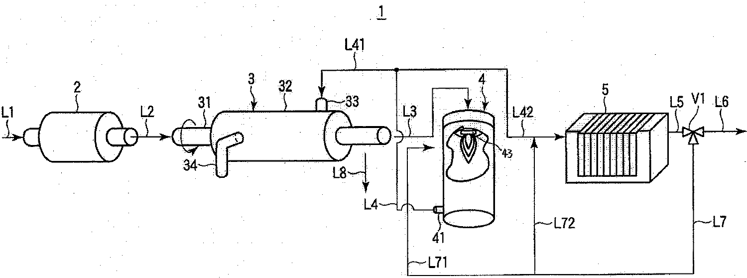
본 실시예의 폐기물 처리 시스템(1)은, 도 1에 나타낸 바와 같이, 건조기(2), 열 분해로(3), 연소 장치(4) 및 열 이용 기기(5)를 구비하고 있다. 이 처리 시스템(1)의 시스템 내는 하류측에 배치된 단수 또는 복수의 블로워(blower)(도시 생략)에 의해 흡인(吸引) 배기되고 있다. 또한, 처리 시스템(1)의 전체는 프로세스 컴퓨터(도시 생략)에 의해 통괄적으로 관리ㆍ제어되고 있다.The
건조기(2)에는, 상류측의 폐기물 투입 장치(도시 생략)로부터 폐기물 공급 라인(L1)을 통해 유기성 폐기물이 투입된다. 건조기(2)는, 유기성 폐기물을 100℃ ~ 300℃의 소정의 온도로 가열해서 유기성 폐기물로부터 수분을 제거한다. 건조기(2)는 다양한 열원을 이용할 수 있다. 열원으로서, 예를 들면 하류측의 열 이용 기기(5)에 의해 열이 이용된 후의 저온 연소 배기 가스나, 열매, 전기 저항 가열 장치, 연소 가열 장치 등의 공지의 범용 가열 장치를 이용할 수 있다. 또한, 폐기물 공급 라인(L1)은, 예를 들면 벨트 컨베이어, 계량기, 슈터 및 호퍼를 포함한다.In the dryer 2, organic waste is thrown in through the waste supply line L1 from an upstream waste input device (not shown). The dryer 2 heats organic waste to predetermined temperature of 100 to 300 degreeC, and removes moisture from organic waste. The dryer 2 can use various heat sources. As a heat source, well-known general purpose heating apparatuses, such as low-temperature combustion exhaust gas after heat is used by the downstream
열 분해로(3)는 환원성 분위기에서 유기성 폐기물을 열 분해한다. 열 분해로(3)는, 회전 구동되는 중공 샤프트실(31)과 이것을 가열하는 가열 재킷(jacket)(32)을 갖는 로터리 킬른 방식 또는 스크루 피더 방식의 횡 배치형의 장치이다. 중공 샤프트실(31)은, 회전 구동 기구(도시 생략)에 의해 회전 가능하게 지지되어 있다. 유기성 폐기물이 폐기물 공급 라인(L2)을 통해 건조기(2)로부터 중공 샤프트실(31)의 중공부에 공급된다. 중공 샤프트실(31) 내의 유기성 폐기물은, 가열 재킷(32)을 통과하는 열매에 의해 가열되어, 열 분해 가스와 열 분해 잔사로 분해된다. 중공 샤프트실(31)의 하류측의 출구 단부(端部)는, 열 분해 가스 라인(L3)을 통해 연소로(4)의 상단 버너(43)에 접속된다. 열 분해 가스는, 중공 샤프트실(31)로부터 열 분해 가스 라인(L3)을 통해 배출되어, 연소로(4)에 도입된다. 또한, 중공 샤프트실(31)의 하류측의 적소(適所)에 탄화물 배출 라인(L8)이 설치되어, 탄화물 배출 라인(L8)을 통해 열 분해 후의 잔사인 탄화물이 중공 샤프트실(31)로부터 배출된다.The
가열 재킷(32)은, 중공 샤프트실(31)의 적어도 일부를 둘러싸는 재킷 용기이다. 열매 공급 관(33)과 열매 배출 관(34)이 가열 재킷(32)에 접속되어 있다. 열매 공급원으로부터 열매 공급 관(33)을 통해 열매로서 고온의 공기, 예를 들면 300℃ ~ 750℃의 드라이 에어(dry air)가 가열 재킷(32) 내에 공급된다. 열매가 중공 샤프트실(31) 내의 유기성 폐기물을 가열한 후에 열매 배출 관(34)을 통해 가열 재킷(32)으로부터 배출된다. 또한, 열매 공급 관(33)과 열매 배출 관(34)을 리턴 라인에 의해 접속해서 순환 회로를 형성하고, 사용 완료의 열매를 열 분해로에 있어서 반복 이용해도 된다. 또한, 열 분해로(3)의 열원으로서, 전기 저항 가열 장치 또는 연소 가열 장치 등의 공지의 범용 가열 장치를 이용할 수 있다. 경제성의 관점에서 다음 공정의 연소로(4)로부터 배출되는 연소 배기 가스를 열원으로서 이용하는 것이 가장 적합하다. 또한, 온도 측정 장치(도시 생략)에는 열전쌍 등의 공지의 범용 계측기가 이용된다.The
연소로(4)는 열 분해 가스의 연소 장치에서, 일단에 연소 분사 방식의 버너를 구비한다. 열 분해 가스 라인(L3) 및 연소용 공기 라인(도시 생략)이 버너에 접속되고, 가연성의 열 분해 가스와 연소용 공기가 소정의 비율로 분사 혼합되어 열 분해 가스가 연소된다. 연소로(4)는 타단에 연소 배기 가스 라인(L4)에 연통하는 배출구(41)를 구비한다. 연소 배기 가스 라인(L4)은 2개의 라인(L41, L42)으로 분기된다. 한 쪽의 라인(L41)은 열 분해로(3)의 열매 공급 관(33)에 접속되고, 다른 쪽의 라인(L42)은 열 이용 기기(5)의 입구에 접속되어 있다. 즉, 연소로(4)로부터 배출되는 연소 배기 가스는, 라인(L4)을 통해서, 그 일부가 라인(L41)을 통해 상류측의 열 분해로(3)의 가열 재킷(32)에 공급되고, 또한 다른 일부가 라인(L42)을 통해 하류측의 열 이용 기기(5)에 공급된다.The
본 실시예에서는 연소 배기 가스 라인을 2개로 분기해서, 연소 배기 가스를 열 분해로(3)와 열 이용 기기(5)에 분배하고 있다. 그러나, 연소 배기 가스 라인을 3개로 분기해서, 연소 배기 가스를 열 분해로(3) 및 열 이용 기기(5)뿐만 아니라, 건조기(2)에도 분배해도 된다. 또한 연소 배기 가스 라인을 분기시키지 않고 프로세스 온도가 높은 기기로부터 프로세스 온도의 낮은 기기로 순서대로 연소 배기 가스를 통과하도록, 각 기기용 연소 배기 가스 라인을 직렬로 접속해도 된다. 또는 연소 배기 가스 라인을 열 이용 기기(5)에만 접속해도 된다.In this embodiment, the combustion exhaust gas line is divided into two, and the combustion exhaust gas is distributed to the
열 이용 기기(5)는, 입구가 연소 배기 가스 라인(L42)에 접속되고, 출구가 저온 연소 배기 가스를 배출하는 배출 라인(L5)에 접속되어 있다. 열 이용 기기(5)로서 예를 들면 폐열 보일러가 이용된다. 열 이용 기기(5)의 본체 내에는, 연소 배기 가스와 열 교환하는 열매가 흐르는 내부 유로가 형성되어 있다. 열 이용 기기(5)의 내부 유로는, 대향 유로, 병행 유로 혹은 서펜타인(serpentine) 형상 유로 등 다양한 형태로 할 수 있다.The
배출 라인(L5)은, 2개의 라인(L6, L7)으로 분기되어 있다. 한 쪽의 라인(L6)은, 더 하류측의 열 이용 기기(도시 생략)에 접속되거나, 또는 무해화(無害化) 장치(도시 생략)를 경유해서 대기에 개방되어 있다.The discharge line L5 is branched into two lines L6 and L7. One line L6 is further connected to a downstream heat utilization apparatus (not shown) or is open to the air via a harmless device (not shown).
다른 쪽의 라인(L7)은, 저온 연소 배기 가스를 연소로(4)에 환류하기 위한 환류 라인(L71) 및 저온 연소 배기 가스를 열 이용 기기(5)에 환류하기 위한 환류 라인(L72)으로 분기되어 있다. 제 1 환류 라인(L71)은, 연소로(4)의 입구측의 연소용 공기에 합류하거나, 또는 연소로(4)의 버너 분사구에 연통하고 있다. 제 2 환류 라인(L72)은, 열 이용 기기(5)의 입구측의 연소 배기 가스 라인(L42)에 합류하거나, 또는 연소 배기 가스 라인(L42)과 병행하여 나아가서 라인(L42)과 함께 열 이용 기기(5)의 내부 유로에서 합류한다.The other line L7 is a reflux line L71 for refluxing the low temperature combustion exhaust gas to the
본 실시예의 작용을 설명한다.The operation of this embodiment will be described.
폐기물 투입 장치(도시 생략)로부터 라인(L1)을 통해 건조기(2) 내에 유기성 폐기물이 투입된다. 건조기(2)는, 투입된 유기성 폐기물을 100℃ ~ 300℃의 온도로 가열해서 유기성 폐기물에 포함되는 수분을 증발시켜, 유기성 폐기물을 수분 함유율이 30% 이하, 바람직하게는 20% 이하의 건조 유기성 폐기물로 한다. 이 건조 유기성 폐기물은 라인(L2)에 의해 열 분해로(3)의 중공 샤프트실(31)에 공급된다. 열 분해로(3)는 300℃ 이상의 온도로 가열되어, 폐기물 중의 유기 성분이 열 분해된다. 이에 따라 유기성 폐기물은 고형분인 탄화물과 기체분인 가연성의 열 분해 가스로 분해된다. 탄화물은, 배출 라인(L8)을 통해 회수 용기(도시 생략)에 배출되어 회수된다. 한편, 가연성의 열 분해 가스는, 라인(L3)을 통해 연소로(4)의 버너에 공급되어서, 연소용 공기와 혼합되어 연소된다. 연소용 공기는, 도시 생략한 컴프레서, 또는 블로워 등에 의해 공급된다. 또한, 연소용 공기는, 컴프레서, 또는 블로워 등으로부터 공급된 공기에 열 이용 기기(5)로부터의 저온 연소 배기 가스를 혼합한 혼합 가스여도 된다.Organic waste is input into the dryer 2 from the waste input apparatus (not shown) via the line L1. The dryer 2 heats the injected organic waste to a temperature of 100 ° C to 300 ° C to evaporate the water contained in the organic waste, and the organic waste contains 30% or less of water and preferably 20% or less of dry organic waste. Shall be. This dry organic waste is supplied to the
연소 배기 가스는, 연소로의 배기구(41)로부터 배출되어, 라인(L4)을 통과한다. 연소 배기 가스의 일부는 라인(L41)을 통과하여, 열매 공급 관(33)으로부터 열 분해로(3)의 가열 재킷(32) 내에 도입되어서, 중공 샤프트실(31) 내의 유기성 폐기물을 열 분해하는 열원으로 된다. 연소 배기 가스의 다른 일부는, 라인(L42)을 통과하여, 열 이용 기기(5)의 내부 유로에 공급되어, 열매와 열 교환된다.The combustion exhaust gas is discharged from the
열 이용 기기(5)에 공급된 연소 배기 가스는, 열 이용 기기(5)에 의해 열 에너지가 회수되어 온도가 500℃ 이하로 저하된다. 그리고 연소 배기 가스는, 저온 연소 배기 가스로서 배출 라인(L5)을 통해 열 이용 기기(5)로부터 배출된다. 이 저온 연소 배기 가스의 일부는, 분기부로부터 환류 라인(7) 및 제 1 환류 라인(L71)을 통해 흘러서 연소로(4)의 버너로부터 분사된다. 또한, 저온 연소 배기 가스의 다른 일부는, 분기부로부터 환류 라인(7), 제 2 환류 라인(L72) 및 라인(L42)을 통해 흘러서 연소 배기 가스와 혼합되어 열 이용 기기(5)의 내부 유로에 다시 공급된다. 또한, 본 실시예의 열 이용 기기로 될 수 있는 기기로서, 공기 예열기(도시 생략), 열 분해로(3), 폐열 보일러(도시 생략), 또는 건조기(2) 등이 있다.As for the combustion exhaust gas supplied to the
본 실시예의 효과를 설명한다.The effect of this embodiment is explained.
본 실시예에 의하면, 열 이용 기기에 의해 열이 이용된 후의 저온 연소 배기 가스는, 적어도 외기보다 온도가 높다. 따라서, 저온 연소 배기 가스의 일부를, 환류 라인(L71)을 이용하여 연소로(4)에 환류해서, 연소로(4)의 버너에 의해 연소용 공기의 일부로서 사용함으로써, 연소용 공기로서 외기만을 사용할 경우에 비해 적은 유량의 열 분해 가스로 연소로(4)의 연소 온도를 유지할 수 있다. 이 때문에, 연소 배기 가스의 양, 즉 저온 연소 배기 가스량이 적어지고, 낭비로 폐기되는 열량을 대폭으로 저감할 수 있어, 열 효율을 향상시킬 수 있다.According to this embodiment, the low-temperature combustion exhaust gas after heat is used by the heat utilization device has a higher temperature than at least the outside air. Therefore, a part of the low temperature combustion exhaust gas is refluxed to the
또한, 열 이용 기기(5)의 재질 등의 이유 때문에 연소 배기 가스의 온도에 상한이 생긴다. 저온 연소 배기 가스를 환류 라인(L72)을 이용해서 연소 배기 가스와 합류시켜, 저온 연소 배기 가스를 연소 배기 가스의 희석 공기로서 사용하면, 연소 배기 가스의 온도를 내릴 수 있다.Moreover, an upper limit arises in the temperature of combustion exhaust gas for the reason of the material of the
유기성 폐기물을 열 분해해서 얻어지는 가연성 가스를 연소할 경우, 폐기물의 종류나 연소 상황에 따라 온실효과 가스인 아산화질소(N2O)가 배출된다. 도 2에, 연소로의 연소 온도(℃)와 연소 배기 가스의 N2O 농도(체적 ppm)의 관계를 조사한 결과를 나타낸다.When the combustible gas obtained by thermal decomposition of organic waste is combusted, nitrous oxide (N 2 O), which is a greenhouse gas, is released depending on the type of waste and the combustion situation. Figure 2 shows the result of examining the relationship between combustion temperature (℃) and combustion N 2 O concentration (volume ppm) in the exhaust gas of the furnace.
이 도 2로부터 명확한 바와 같이, N2O 농도는, 연소로의 연소 온도가 높아짐에 따라 감소하고, 연소 온도 900℃ 이상에서 크게 감소한다. 특히 연소 온도 950℃ 이상의 온도 범위에서는 N2O 농도는 거의 변화되지 않게 된다. N2O 농도를 내리기 위해서는, 높은 연소 온도가 필요해진다. 본 실시예는, 외기에 비해 고온인 저온 연소 배기 가스를 연소 공기의 일부로서 사용하므로, 보다 적은 유량으로 연소 온도를 고온으로 유지할 수 있다. 따라서, 실시예에 의하면, 연소로(4)로부터 배출되는 연소 배기 가스 중의 N2O 농도를 낮게 할 수 있다.As is apparent from FIG. 2, the N 2 O concentration decreases as the combustion temperature of the combustion furnace increases, and greatly decreases at a combustion temperature of 900 ° C. or higher. In particular, the combustion temperature over the
(제 2 실시예)(Second Embodiment)
도 3을 참조해서 제 2 실시예를 설명한다. 또한, 본 실시예가 상기의 실시예와 중복되는 부분의 설명을 생략한다.A second embodiment will be described with reference to FIG. In addition, description of the part which this embodiment overlaps with said embodiment is abbreviate | omitted.
본 실시예의 폐기물 처리 시스템(1A)은, 연소로(4)와 열 이용 기기(5)를 연결시키는 라인(L42) 상에 집진기(10)를 더 구비하고 있다. 집진기(10)는, 예를 들면 상부에 도입된 연소 배기 가스를 선회류(旋回流)로서 하강시켜, 연소 배기 가스 중의 고형분을 가스분으로부터 원심 분리하는 사이클론이다. 또한, 연소 배기 가스 중의 고형분은, 불연성 분진을 포함하는 매진 등이다.The
열 분해 가스 중에 고형 불연물의 분진이 혼입될 경우, 연소로(4)에서 이 고형 불연물은 연소될 수 없고, 연소 배기 가스 중에 매진으로서 혼입된다. 매진은 대기 오염 물질이다. 또한 매진이 열 이용 기기의 내부 유로나 내벽에 부착되면, 부착된 매진이 열 전도율을 저하시켜 열 이용 기기의 열 효율이 저하된다. 그러나, 본 실시예의 시스템에 의하면, 집진기가 연소 배기 가스로부터 매진을 분리 제거하므로, 열 이용 기기의 열 전도율의 저하를 방지할 수 있다. 또한 본 실시예의 시스템에 의하면, 대기 오염 물질의 대기로의 방출도 저감할 수 있다. 또한, 배출되는 연소 배기 가스 중의 N2O 농도를 낮게 할 수 있는 효과는, 제 1 실시예와 동일하다.When dust of solid incombustibles is mixed in the pyrolysis gas, the solid incombustibles cannot be combusted in the
(제 3 실시예)(Third Embodiment)
도 4를 참조해서 제 3 실시예를 설명한다. 또한, 본 실시예가 상기의 실시예와 중복되는 부분의 설명을 생략한다.A third embodiment will be described with reference to FIG. In addition, description of the part which this embodiment overlaps with said embodiment is abbreviate | omitted.
본 실시예의 폐기물 처리 시스템(1B)은, 보조 연료 공급 장치(11)를 더 구비하고 있다. 보조 연료 공급 장치(11)는, 열 분해 가스 라인(L3)에 접속된 주입 라인(L9)을 갖는다. 보조 연료 공급 장치(11)는, 열 분해 가스 라인(L3)을 흐르는 열 분해 가스에 보조 연료를 주입하고, 연소로(4)의 버너로부터 보조 연료를 연소 분사시킨다. 또한, 주입 라인(L9)은, 반드시 열 분해 가스 라인(L3)에 접속되지 않아도 되고, 연소로(4)에 별도 버너를 설치하고, 이것에 접속해도 된다.The
연소로(4)는, 연소로(4)의 온도를 유지하는 열원으로서 가연성의 열 분해 가스를 이용한다. 열 이용 기기(5)에 의해 회수되는 열량이 많아질 경우에, 열 분해 가스가 발생하는 열량이 일정하면, 저온 연소 배기 가스의 온도가 저하해서 결로(結露) 등의 결함이 생길 경우가 있다. 저온 연소 배기 가스의 온도를 유지한 채로 열 이용 기기(5)에 의해 회수되는 열량을 많게 하기 위해서는 열 분해 가스의 열량을 올리면 된다. 이 경우, 열 분해 가스의 원료인 유기성 폐기물의 처리량을 크게 할 필요가 있다. 그러나, 열 분해로의 사양 상의 제약에 의해 유기성 폐기물의 처리량에 한계가 있다.The
그래서, 본 실시예에서는, 열 이용 기기에서 열원이 부족할 경우에, 보조 연료 공급 장치(11)로부터 메탄 가스 등의 보조 연료를 연소로(4)의 연료로서 주입한다. 이에 따라, 열원의 부족을 해소할 수 있다. 또한, 본 실시예는, 보조 연료 공급 장치(11)로부터의 보조 연료를, 유기성 폐기물이 투입되지 않는 폐기물 처리 시스템의 기동시 및 정지시의 연료로서도 사용할 수 있는 이점도 있다. 또한, 배출되는 연소 배기 가스 중의 N2O 농도를 낮게 할 수 있는 효과는, 제 1 실시예와 동일하다.Therefore, in the present embodiment, when the heat source is insufficient in the heat utilizing device, auxiliary fuel such as methane gas is injected from the auxiliary
이상 기술한 적어도 하나의 실시예의 폐기물 처리 시스템에 의하면, 아산화질소의 발생을 억제할 수 있는 폐기물 처리 시스템을 제공할 수 있다.According to the waste treatment system of at least one embodiment described above, the waste treatment system which can suppress generation | occurrence | production of nitrous oxide can be provided.
본 발명의 몇 가지의 실시형태를 설명했지만, 이들 실시형태는, 예로서 제시한 것이고, 발명의 범위를 한정하는 것은 의도하고 있지 않다. 이들 신규인 실시형태는, 그 밖의 다양한 형태로 실시되는 것이 가능하고, 발명의 요지를 일탈하지 않는 범위에서, 다양한 생략, 치환, 변경을 행할 수 있다. 이들 실시형태나 그 변형은, 발명의 범위나 요지에 포함되는 동시에, 특허청구범위에 기재된 발명과 그 균등한 범위에 포함된다.While certain embodiments have been described, these embodiments have been presented by way of example only, and are not intended to limit the scope of the inventions. These novel embodiments can be implemented in various other forms, and various omissions, substitutions, and changes can be made without departing from the scope of the invention. These embodiments and their modifications fall within the scope and spirit of the invention and are included in the scope of equivalents of the invention described in the claims.
1 : 폐기물 처리 시스템
2 : 건조기
3 : 열 분해로
4 : 연소 장치
5 : 열 이용 기기
10 : 집진기
11 : 보조 연료 공급 장치
31 : 중공 샤프트실
32 : 가열 재킷
33 : 열매 공급 관
34 : 열매 배출 관
41 : 배출구
43 : 버너1: waste disposal system
2: dryer
3: pyrolysis furnace
4: combustion device
5: heat-using device
10: dust collector
11: auxiliary fuel supply
31: hollow shaft seal
32: heating jacket
33: fruit supply pipe
34: fruit discharge tube
41: outlet
43: burner
Claims (8)
아산화질소(N2O)의 발생이 억제되도록, 상기 열 분해로에서 발생한 가연성의 열 분해 가스를 900℃ 이상 1000℃ 이하의 온도에서 연소하는 연소로와,
상기 연소로에서 발생한 연소 배기 가스를 열원으로서 이용하는 열 이용 기기와,
상기 열 이용 기기에 의해 이용되어 온도가 저하한 열 이용 후의 저온 연소 배기 가스를, 상기 열 이용 기기로부터 상기 열 이용 기기보다 상류측에 배치된 기기에 환류(還流)시켜, 상기 연소로에서 연소 공기로서, 또는 상기 열 이용 기기에서 희석 공기로서 이용시키는 환류 라인을 구비하는 것을 특징으로 하는 폐기물 처리 시스템.A thermal decomposition furnace that receives an organic waste containing organic nitrogen and thermally decomposes the organic waste in a high-temperature reducing atmosphere,
A combustion furnace for combusting the flammable pyrolysis gas generated in the pyrolysis furnace at a temperature of 900 ° C or more and 1000 ° C or less so that generation of nitrous oxide (N 2 O) is suppressed,
A heat utilization apparatus using combustion exhaust gas generated in the combustion furnace as a heat source;
The low-temperature combustion exhaust gas after the use of heat used by the heat utilization device and the temperature is lowered is refluxed from the heat use device to the device arranged upstream from the heat use device, so that combustion air is generated in the combustion furnace. Or a reflux line for use as dilution air in the heat utilization device.
상기 열 분해로보다 상류측에 배치되며, 상기 유기성 폐기물을 가열해서 상기 유기성 폐기물로부터 수분을 증발시킴으로써 상기 유기성 폐기물의 함유 수분을 감소시키는 건조기를 더 갖는 것을 특징으로 하는 폐기물 처리 시스템.The method of claim 1,
And a dryer disposed more upstream than the thermal decomposition furnace, the dryer further reducing the moisture content of the organic waste by heating the organic waste to evaporate water from the organic waste.
상기 열 이용 기기와 상기 연소로 사이에 집진기를 더 갖는 것을 특징으로 하는 폐기물 처리 시스템.The method according to claim 1 or 3,
And a dust collector between the heat utilization device and the combustion furnace.
상기 연소로에 보조 연료를 공급하는 보조 연료 공급 장치를 더 갖는 것을 특징으로 하는 폐기물 처리 시스템.The method according to claim 1 or 3,
And an auxiliary fuel supply device for supplying auxiliary fuel to the combustion furnace.
상기 연소로가 배출하는 상기 연소 배기 가스를 상기 열 분해로에 공급하는 라인을 갖는 것을 특징으로 하는 폐기물 처리 시스템.The method of claim 1,
And a line for supplying the combustion exhaust gas discharged from the combustion furnace to the pyrolysis furnace.
상기 열 분해로는, 유기성 폐기물이 공급되는 중공 샤프트실과 상기 중공 샤프트실을 가열하는 가열 재킷(jacket)을 갖고, 상기 연소 배기 가스를 상기 열 분해로에 공급하는 상기 라인은, 상기 연소 배기 가스를 상기 가열 재킷에 공급하는 것을 특징으로 하는 폐기물 처리 시스템.The method of claim 7, wherein
The pyrolysis furnace has a hollow shaft chamber to which organic waste is supplied and a heating jacket for heating the hollow shaft chamber, and the line for supplying the combustion exhaust gas to the pyrolysis furnace supplies the combustion exhaust gas. And a waste treatment system for supplying the heating jacket.
Applications Claiming Priority (2)
| Application Number | Priority Date | Filing Date | Title |
|---|---|---|---|
| JPJP-P-2010-056634 | 2010-03-12 | ||
| JP2010056634A JP5143169B2 (en) | 2010-03-12 | 2010-03-12 | Waste treatment system |
Publications (2)
| Publication Number | Publication Date |
|---|---|
| KR20110103315A KR20110103315A (en) | 2011-09-20 |
| KR101292233B1 true KR101292233B1 (en) | 2013-08-01 |
Family
ID=44601114
Family Applications (1)
| Application Number | Title | Priority Date | Filing Date |
|---|---|---|---|
| KR1020110009230A KR101292233B1 (en) | 2010-03-12 | 2011-01-31 | Waste treating system |
Country Status (3)
| Country | Link |
|---|---|
| JP (1) | JP5143169B2 (en) |
| KR (1) | KR101292233B1 (en) |
| CN (1) | CN102192511B (en) |
Families Citing this family (9)
| Publication number | Priority date | Publication date | Assignee | Title |
|---|---|---|---|---|
| JP5767938B2 (en) * | 2011-10-19 | 2015-08-26 | 新日鉄住金エンジニアリング株式会社 | Volume reduction method for low-level radioactive waste |
| CN103900089B (en) * | 2012-12-29 | 2016-05-18 | 中国中化股份有限公司 | The dirty salt processing method of a kind of industry containing organic pollution |
| CN104791803B (en) * | 2014-01-21 | 2018-11-23 | 无锡高尔环保科技有限公司 | A kind of garbage combustion device and its burning process |
| EP3212242B1 (en) * | 2014-10-27 | 2023-08-23 | Rosmarin Holdings Limited | Method and device for sanitizing biogenic wastes with waste gases from incineration devices |
| CN105043092A (en) * | 2015-09-05 | 2015-11-11 | 吉首大学 | Manganese processing rotary kiln with gas furnace supplying heat |
| CN105327930A (en) * | 2015-11-13 | 2016-02-17 | 北京神雾环境能源科技集团股份有限公司 | Power generation system using household garbage and power generation method thereof |
| CN109945195A (en) * | 2019-03-20 | 2019-06-28 | 北京中和锦程科技有限公司 | Organic waste low temperature magnetizes cracking apparatus |
| TWI777434B (en) * | 2020-03-18 | 2022-09-11 | 日商住友重機械工業股份有限公司 | heat treatment system |
| CN115560615B (en) * | 2022-11-21 | 2023-03-31 | 山东福尔有限公司 | Pyridine waste heat utilization device |
Citations (2)
| Publication number | Priority date | Publication date | Assignee | Title |
|---|---|---|---|---|
| JP2007225223A (en) * | 2006-02-24 | 2007-09-06 | Mitsubishi Heavy Ind Ltd | Pyrolysis gas treating method and its device for highly hydrous organic matter carbonizing system |
| JP2009097758A (en) * | 2007-10-15 | 2009-05-07 | Toshiba Corp | Device for producing fuel from sludge |
Family Cites Families (4)
| Publication number | Priority date | Publication date | Assignee | Title |
|---|---|---|---|---|
| JP3806428B2 (en) * | 2004-01-15 | 2006-08-09 | 三菱重工業株式会社 | Method and apparatus for carbonizing sludge and power generation method |
| JP5300237B2 (en) * | 2007-10-11 | 2013-09-25 | 株式会社東芝 | Sludge fuel plant |
| JP2009225223A (en) * | 2008-03-18 | 2009-10-01 | Epson Toyocom Corp | Piezoelectric device |
| JP5297066B2 (en) * | 2008-03-28 | 2013-09-25 | 三菱重工環境・化学エンジニアリング株式会社 | Pyrolysis gas treatment method and apparatus in sludge carbonization equipment |
-
2010
- 2010-03-12 JP JP2010056634A patent/JP5143169B2/en not_active Expired - Fee Related
-
2011
- 2011-01-31 CN CN2011100341553A patent/CN102192511B/en not_active Expired - Fee Related
- 2011-01-31 KR KR1020110009230A patent/KR101292233B1/en active IP Right Grant
Patent Citations (2)
| Publication number | Priority date | Publication date | Assignee | Title |
|---|---|---|---|---|
| JP2007225223A (en) * | 2006-02-24 | 2007-09-06 | Mitsubishi Heavy Ind Ltd | Pyrolysis gas treating method and its device for highly hydrous organic matter carbonizing system |
| JP2009097758A (en) * | 2007-10-15 | 2009-05-07 | Toshiba Corp | Device for producing fuel from sludge |
Also Published As
| Publication number | Publication date |
|---|---|
| KR20110103315A (en) | 2011-09-20 |
| CN102192511A (en) | 2011-09-21 |
| JP2011190969A (en) | 2011-09-29 |
| CN102192511B (en) | 2013-11-06 |
| JP5143169B2 (en) | 2013-02-13 |
Similar Documents
| Publication | Publication Date | Title |
|---|---|---|
| KR101292233B1 (en) | Waste treating system | |
| JP4996416B2 (en) | Sludge fuel plant | |
| US7832343B2 (en) | Pyrolyzer with dual processing shafts | |
| JP2009091496A (en) | Apparatus for converting sludge into fuel | |
| RU2009133375A (en) | METHOD AND INSTALLATION FOR DRYING DUSTY FUELS BEFORE ALL SUBMITTED FOR GASIFICATION OF FUELS | |
| Pickard et al. | Co-firing coal with biomass in oxygen-and carbon dioxide-enriched atmospheres for CCS applications | |
| JP5634158B2 (en) | Biomass carbonization apparatus and method for producing carbide | |
| US10450523B2 (en) | Method and apparatus for torrefaction of biomass with a cyclonic bed reactor | |
| TW200905139A (en) | Pyrolysis gas treating method and its device for highly hydrous organic matter carbonizing system | |
| KR101224032B1 (en) | Combustion apparatus | |
| CN101373070B (en) | Heat decomposition gas processing method and apparatus of carbonization processing system containing water | |
| JP4483553B2 (en) | Gasification processing method and apparatus | |
| US9068121B1 (en) | Systems, apparatus and methods for optimizing the pyrolysis of biomass using thermal expansion | |
| RU2338770C1 (en) | Treatment method of wood biomass in form of combustive chips with receiving of bio-oil and wood coal and drying-retort module for treatment of wood biomass in form of combustive chips with receiving of bio-oil and wood coal | |
| PT2847516E (en) | Improvements in waste processing | |
| CN105371280B (en) | The apparatus and method that a kind of solid waste organic substance cleaning is burned | |
| JP2007163078A (en) | Waste disposal method and device | |
| JP5510782B2 (en) | Waste melting treatment method and waste melting treatment apparatus | |
| JP2008215661A (en) | Combustion furnace, waste gasification system and combustible gas treatment method | |
| JP2009138089A (en) | Multistage screw carbonization device | |
| RU89670U1 (en) | DEVICE FOR DISPOSAL OF WET WASTE CONTAINING ORGANIC MATERIALS | |
| JP5411312B2 (en) | Organic waste processing apparatus, organic waste processing method, and control apparatus | |
| WO2011014094A1 (en) | Method and device for recycling moist waste matter comprising organic materials | |
| JP2005336233A (en) | Organic substance gasification system using carbonization furnace of multiple stage | |
| CN212777361U (en) | Organic waste treatment system |
Legal Events
| Date | Code | Title | Description |
|---|---|---|---|
| A201 | Request for examination | ||
| E902 | Notification of reason for refusal | ||
| E701 | Decision to grant or registration of patent right | ||
| GRNT | Written decision to grant | ||
| FPAY | Annual fee payment |
Payment date: 20160628 Year of fee payment: 4 |
|
| FPAY | Annual fee payment |
Payment date: 20170704 Year of fee payment: 5 |
|
| FPAY | Annual fee payment |
Payment date: 20180628 Year of fee payment: 6 |