KR101248328B1 - Projection system with compensation of intensity variations and compensation element therefor - Google Patents
Projection system with compensation of intensity variations and compensation element therefor Download PDFInfo
- Publication number
- KR101248328B1 KR101248328B1 KR1020117023187A KR20117023187A KR101248328B1 KR 101248328 B1 KR101248328 B1 KR 101248328B1 KR 1020117023187 A KR1020117023187 A KR 1020117023187A KR 20117023187 A KR20117023187 A KR 20117023187A KR 101248328 B1 KR101248328 B1 KR 101248328B1
- Authority
- KR
- South Korea
- Prior art keywords
- layer
- layer thickness
- projection objective
- reflectance
- modulation
- Prior art date
Links
Images


Classifications
-
- G—PHYSICS
- G02—OPTICS
- G02B—OPTICAL ELEMENTS, SYSTEMS OR APPARATUS
- G02B13/00—Optical objectives specially designed for the purposes specified below
- G02B13/02—Telephoto objectives, i.e. systems of the type + - in which the distance from the front vertex to the image plane is less than the equivalent focal length
-
- H—ELECTRICITY
- H01—ELECTRIC ELEMENTS
- H01L—SEMICONDUCTOR DEVICES NOT COVERED BY CLASS H10
- H01L21/00—Processes or apparatus adapted for the manufacture or treatment of semiconductor or solid state devices or of parts thereof
- H01L21/02—Manufacture or treatment of semiconductor devices or of parts thereof
- H01L21/027—Making masks on semiconductor bodies for further photolithographic processing not provided for in group H01L21/18 or H01L21/34
- H01L21/0271—Making masks on semiconductor bodies for further photolithographic processing not provided for in group H01L21/18 or H01L21/34 comprising organic layers
- H01L21/0273—Making masks on semiconductor bodies for further photolithographic processing not provided for in group H01L21/18 or H01L21/34 comprising organic layers characterised by the treatment of photoresist layers
- H01L21/0274—Photolithographic processes
-
- G—PHYSICS
- G02—OPTICS
- G02B—OPTICAL ELEMENTS, SYSTEMS OR APPARATUS
- G02B17/00—Systems with reflecting surfaces, with or without refracting elements
- G02B17/08—Catadioptric systems
- G02B17/0804—Catadioptric systems using two curved mirrors
- G02B17/0812—Catadioptric systems using two curved mirrors off-axis or unobscured systems in which all of the mirrors share a common axis of rotational symmetry
-
- G—PHYSICS
- G02—OPTICS
- G02B—OPTICAL ELEMENTS, SYSTEMS OR APPARATUS
- G02B17/00—Systems with reflecting surfaces, with or without refracting elements
- G02B17/08—Catadioptric systems
- G02B17/0892—Catadioptric systems specially adapted for the UV
-
- G—PHYSICS
- G03—PHOTOGRAPHY; CINEMATOGRAPHY; ANALOGOUS TECHNIQUES USING WAVES OTHER THAN OPTICAL WAVES; ELECTROGRAPHY; HOLOGRAPHY
- G03B—APPARATUS OR ARRANGEMENTS FOR TAKING PHOTOGRAPHS OR FOR PROJECTING OR VIEWING THEM; APPARATUS OR ARRANGEMENTS EMPLOYING ANALOGOUS TECHNIQUES USING WAVES OTHER THAN OPTICAL WAVES; ACCESSORIES THEREFOR
- G03B27/00—Photographic printing apparatus
- G03B27/32—Projection printing apparatus, e.g. enlarger, copying camera
- G03B27/52—Details
- G03B27/54—Lamp housings; Illuminating means
- G03B27/545—Lamp housings; Illuminating means for enlargers
- G03B27/547—Lamp housings; Illuminating means for enlargers colour mixing heads
-
- G—PHYSICS
- G03—PHOTOGRAPHY; CINEMATOGRAPHY; ANALOGOUS TECHNIQUES USING WAVES OTHER THAN OPTICAL WAVES; ELECTROGRAPHY; HOLOGRAPHY
- G03B—APPARATUS OR ARRANGEMENTS FOR TAKING PHOTOGRAPHS OR FOR PROJECTING OR VIEWING THEM; APPARATUS OR ARRANGEMENTS EMPLOYING ANALOGOUS TECHNIQUES USING WAVES OTHER THAN OPTICAL WAVES; ACCESSORIES THEREFOR
- G03B27/00—Photographic printing apparatus
- G03B27/72—Controlling or varying light intensity, spectral composition, or exposure time in photographic printing apparatus
- G03B27/725—Optical projection devices wherein the contrast is controlled electrically (e.g. cathode ray tube masking)
-
- G—PHYSICS
- G03—PHOTOGRAPHY; CINEMATOGRAPHY; ANALOGOUS TECHNIQUES USING WAVES OTHER THAN OPTICAL WAVES; ELECTROGRAPHY; HOLOGRAPHY
- G03F—PHOTOMECHANICAL PRODUCTION OF TEXTURED OR PATTERNED SURFACES, e.g. FOR PRINTING, FOR PROCESSING OF SEMICONDUCTOR DEVICES; MATERIALS THEREFOR; ORIGINALS THEREFOR; APPARATUS SPECIALLY ADAPTED THEREFOR
- G03F7/00—Photomechanical, e.g. photolithographic, production of textured or patterned surfaces, e.g. printing surfaces; Materials therefor, e.g. comprising photoresists; Apparatus specially adapted therefor
- G03F7/70—Microphotolithographic exposure; Apparatus therefor
- G03F7/70058—Mask illumination systems
- G03F7/70133—Measurement of illumination distribution, in pupil plane or field plane
-
- G—PHYSICS
- G03—PHOTOGRAPHY; CINEMATOGRAPHY; ANALOGOUS TECHNIQUES USING WAVES OTHER THAN OPTICAL WAVES; ELECTROGRAPHY; HOLOGRAPHY
- G03F—PHOTOMECHANICAL PRODUCTION OF TEXTURED OR PATTERNED SURFACES, e.g. FOR PRINTING, FOR PROCESSING OF SEMICONDUCTOR DEVICES; MATERIALS THEREFOR; ORIGINALS THEREFOR; APPARATUS SPECIALLY ADAPTED THEREFOR
- G03F7/00—Photomechanical, e.g. photolithographic, production of textured or patterned surfaces, e.g. printing surfaces; Materials therefor, e.g. comprising photoresists; Apparatus specially adapted therefor
- G03F7/70—Microphotolithographic exposure; Apparatus therefor
- G03F7/70216—Mask projection systems
- G03F7/70308—Optical correction elements, filters or phase plates for manipulating imaging light, e.g. intensity, wavelength, polarisation, phase or image shift
Abstract
투사 대물렌즈의 물체 평면에 배열된 패턴을 투사 대물렌즈의 이미지 평면에 결상하기 위한 투사 대물렌즈에서, 기판을 갖는 적어도 하나의 광학 소자가 구비되는데, 상기 기판의 적어도 하나의 면은 상기 광학 소자의 이용가능한 단면에 걸쳐 반사율 및/또는 투과율의 큰 공간적 변조를 갖는 간섭층 시스템으로 덮이며, 변조는 투사 대물렌즈의 잔여 소자들의 공간적 투과율 분포에 적합화되어 퓨필 면에서 측정된 방사의 강도 분포가 간섭층 시스템을 갖지 않은 투사 대물렌즈에 비해 실질적으로 감소된 공간 변조를 갖도록 한다.In a projection objective for imaging a pattern arranged on an object plane of a projection objective lens on an image plane of a projection objective lens, at least one optical element having a substrate is provided, wherein at least one surface of the substrate is formed of the optical element. Covered by an interference layer system with large spatial modulation of reflectance and / or transmittance across the available cross sections, the modulation is adapted to the spatial transmission distribution of the remaining elements of the projection objective so that the intensity distribution of the measured radiation at the pupil plane interferes. It has a substantially reduced spatial modulation compared to a projection objective without a layer system.
Description
본 발명은 강도 변동이 보상된 투사 시스템 및 이를 위한 보상 요소에 관한 것이다.The present invention relates to a projection system in which intensity variations are compensated for and a compensation element therefor.
본 발명은 또한 투사 대물렌즈의 물체 평면에 배열된 패턴을 투사 대물렌즈의 이미지 평면에 결상하는 투사 대물렌즈에 관한 것이고, 또한 기판을 갖는 광학 소자에 관한 것으로서, 상기 광학 소자의 적어도 하나의 기판 면은 간섭층 시스템(interference layer system)으로 덮인다. 광학 소자는 카타디옵트릭 또는 디옵트릭 투사 대물렌즈에 합체화되기 위하여 제공될 수도 있고 또는 후자에 합체화될 수 있다.The present invention also relates to a projection objective lens for forming a pattern arranged on an object plane of a projection objective lens on an image plane of a projection objective lens, and also relates to an optical element having a substrate, wherein at least one substrate surface of the optical element is provided. Is covered by an interference layer system. The optical element may be provided for incorporation into a catadioptric or dioptric projection objective or may be incorporated into the latter.
본 발명은 또한 투사 노광 장치에 관한 것으로, 특히 본원 우선일 전에 공개되지 않은 미국 특허출원 제60/592208호, 제60/530978호, 제60/591775호 또는 제60/612823호에 상세하게 기재된 바와 같은 액침 리소그래피용 투사 노광 장치에 관한 것이다. 여기서 액침 매질은 액체, 바람직하게는 물이다.The present invention also relates to a projection exposure apparatus, in particular as described in detail in U.S. Patent Application Nos. 60/592208, 60/530978, 60/591775 or 60/612823, which were not published prior to this application date. The same relates to a projection exposure apparatus for immersion lithography. The immersion medium here is a liquid, preferably water.
본 발명은 또한 투사 노광 장치에 관한 것으로, 특히 예컨대 미국 공개특허공보 제2003/174301호에 개시된 것과 같은 근접장 리소그래피(near field lithography)-고체 액침 렌즈(SIL; solid immersioon lens) 리소그래피와 유의어-용 투사 노광 장치에 관한 것이다.The present invention also relates to a projection exposure apparatus, in particular for near field lithography (solid immersioon lens) lithography such as that disclosed in US Patent Publication No. 2003/174301 and for synonym-based projection. It relates to an exposure apparatus.
마이크로 리소그래피용 투사 노광 장치는 반도체 소자 및 다른 미세 패턴 소자 제조에 사용된다. 이는 포토마스크 또는 레티클(이하에서는 통상적으로 마스크 또는 레티클이라 함)로부터 패턴을 감광층으로 코팅된 물체 상에, 예컨대 포토리지스트로 코팅된 반도체 웨이퍼 상에 매우 고해상도로 축소된 스케일로 투사하는 역할을 한다.Projection exposure apparatus for microlithography is used in the manufacture of semiconductor devices and other fine pattern devices. This serves to project the pattern from the photomask or reticle (hereinafter commonly referred to as a mask or reticle) onto an object coated with a photosensitive layer, such as on a photoresist coated semiconductor wafer at a reduced scale at a very high resolution. .
반도체 소자를 포토리소그래피법으로 패터닝하는 공정에 있어서, 모든 구조 방향들 특히 수평 구조 및 수직 구조가 본질적으로 동일한 결상 품질로 결상되어야 한다는 것이 매우 중요하다. 리소그래피 대물렌즈들의 결상 품질은 수차의 보상 상태뿐만 아니라 필드에 있어서의 강도 프로파일 및 각 필드 지점의 퓨필에 있어서의 강도 프로파일에 의해 결정된다. 필드 및 퓨필에서의 프로파일들은 가능한 한 균일해야 한다. 이미지 평면에서의 국지적인 강도 변조는 그 중에서도 특히 피해야만 하는데, 이는 오늘날 통상적인 2성분 리지스트 물질이 매우 비선형적인 민감도 특성 곡선을 갖기 때문인데, 이 곡선은 문턱 강도 이하에서는 노광이 이루어지지 않으나 문턱 강도 이상에서는 노광이 이루어진다는 것으로 1차 근사로 모델링될 수 있다. 그 결과, 공간적인 강도 프로파일은 반도체 소자 상에 형성된 구조체들의 폭에 직접적인 영향을 준다. 필드에 있어서 그리고 상이한 구조 방향들에 있어서 선폭이 더욱 균일하면 균일할수록 완성된 반도체 소자를 사용할 때 클럭 주파수(clock frequency)가 더 높을 것이며 따라서 완성된 반도체 소자의 성능 및 가격 역시 더 높을 것이다. 따라서, 최소 배선폭(CD; critical dimension)의 변동은 중요한 품질 판단 기준이다.In the process of patterning a semiconductor device by photolithography, it is very important that all the structural directions, in particular the horizontal structure and the vertical structure, are formed with essentially the same imaging quality. The image quality of the lithographic objectives is determined not only by the compensation state of the aberration, but also by the intensity profile in the field and the intensity profile in the pupil of each field point. Profiles in the field and pupil should be as uniform as possible. Local intensity modulation in the image plane should be especially avoided, because today's conventional two-component resist materials have very nonlinear sensitivity curves, which are not exposed below the threshold intensity, but the threshold Beyond the intensity, exposure can be modeled as a first order approximation. As a result, the spatial intensity profile directly affects the width of the structures formed on the semiconductor device. The more uniform the line width in the field and in different structural directions, the higher the clock frequency will be when using the finished semiconductor device and therefore the performance and cost of the finished semiconductor device will also be higher. Therefore, variation in critical dimension (CD) is an important quality criterion.
최소 배선폭의 변동은 상이한 원인들, 개별적으로 또는 축적적으로 작용하는 원인들을 가질 수 있다. 특히 편광으로 작동하는 시스템들에 있어서, 입사각에 의존하는 간섭층 시스템들의 반사율 또는 투과율 특성은 필드 및 퓨필에 있어서 강도의 비균일성을 초래할 수 있다. 이 문제 영역은 순수 굴절(refractive)(디옵트릭) 결상 시스템들의 경우에 발생할 수 있다. 상기와 같은 원인들은 특히 카타디옵트릭 투사 대물렌즈들, 즉 굴절 소자들 및 반사 소자들, 특히 렌즈들 및 결상 거울들이 결합된 시스템에서 발생할 수 있다. 결상 거울 면들을 이용할 때, 만일 모호하게(obscuration) 하지 않거나 비네팅(vignetting)이 일어나지 않도록 하는 결상을 달성해야 한다면, 빔 스플리터를 이용하는 것이 바람직하다. 기하학적 빔 스플리팅을 갖는 시스템들 및 물리적인 빔 스플리팅 예컨대 편광 빔 스플리팅을 갖는 시스템들이 가능하다. 그러한 투사 대물렌즈들에 있어서 거울 면들을 사용하는 것은 결상 중 발생하는 최소 배선폭 변동에 기여할 것이다.The variation in the minimum wiring width can have different causes, ones that act individually or cumulatively. Particularly in systems operating with polarization, the reflectance or transmittance characteristics of interfering layer systems depending on the angle of incidence can lead to non-uniformity of intensity in the field and pupil. This problem area can occur in the case of pure refracting (dioptric) imaging systems. Such causes can arise in particular in systems in which catadioptric projection objectives, ie refractive elements and reflective elements, in particular lenses and imaging mirrors, are combined. When using imaging mirror surfaces, it is desirable to use a beam splitter if it is necessary to achieve an imaging that does not obscuration or vignetting. Systems with geometric beam splitting and systems with physical beam splitting such as polarizing beam splitting are possible. The use of mirror surfaces in such projection objectives will contribute to the minimum wiring width variation that occurs during imaging.
칼슘 플루오라이드와 같은 플루오라이드 결정 및 합성 석영 글래스를 사용할 때, 이 물질들이 복굴절 물질이라는 점을 더욱 고려해야만 한다. 이 물질들은 그것을 통과하는 광의 유도된 및/또는 본질적인 복굴절 때문에 편광-변동 효과를 유발하는데, 이는 또한 최소 배선폭 변동 발생에 기여한다. 마지막으로, 투명 소자들에 있어서 예컨대 산란 센터(scattering center) 또는 찰흔(striation)과 같은 물질 결함 또한 강도 분포의 비균일성에 이르게 할 것이다.When using fluoride crystals such as calcium fluoride and synthetic quartz glass, further consideration should be given to the fact that these materials are birefringent materials. These materials cause a polarization-varying effect due to the induced and / or intrinsic birefringence of the light passing therethrough, which also contributes to the occurrence of minimum wiring width variations. Finally, material defects, such as scattering centers or scratches, for transparent devices will also lead to non-uniformity of intensity distribution.
또한, 흡수성 광학 요소들, 특히 액침 매질, 특히 액침 액체, 고체 액침 렌즈(SIL; solid immersion lens) 또는 다른 것, 고굴절율의 굴절성 광학 물질은 필드 및 퓨필에 의존하는 투과율 분포에 이르게 하며 따라서 투과율 프로파일에서 오차가 발생하는 것에 이르게 한다.In addition, absorbent optical elements, in particular immersion media, in particular immersion liquids, solid immersion lenses (SILs) or others, high refractive index refractive optical materials lead to transmission distributions that are dependent on the field and pupil and thus transmittance This leads to an error in the profile.
출원인에 의한 2004년 1월 19일자 독일 특허출원 DE 102004002634.3을 기초출원으로 한 우선권주장출원인 출원인에 의한 2004년 2월 24일자 국제특허출원 PCT/EP2004/001779은 액침 리소그래피용으로 디자인된 마이크로리소그래피 노광 장치를 개시하고 있는데, 투사 대물렌즈는 투과율 필터를 포함하며, 이 투과율 필터는, 이미지측 최종 광학 요소와 투사 대물렌즈의 이미지 평면 사이에 형성되며 이미지측 상의 최종 광학 요소로부터 액침 액체로 채워진 액침 사이공간(interspace)에 입사각을 가지고 진입하는 광이 입사각이 작을수록 더 강하게 감쇄되는 방식으로 디자인되어 투사 대물렌즈에 배열된다. 이 PCT 출원의 개시사항은 본원에 참조로서 포함된다.International Patent Application PCT / EP2004 / 001779, filed February 24, 2004 by Applicant Priority Applicant based on German patent application DE 102004002634.3 filed on January 19, 2004 by Applicant, is a microlithography exposure apparatus designed for immersion lithography. The projection objective lens comprises a transmission filter, the transmission filter formed between an image side final optical element and the image plane of the projection objective lens and filled with an immersion liquid from the final optical element on the image side. The light entering with the angle of incidence into the interspace is designed in such a way that the smaller the angle of incidence is attenuated more strongly and arranged in the projection objective. The disclosure of this PCT application is incorporated herein by reference.
투사 노광 장치가 사용된 기간이 증가함에 따라, 상기 투과율 분포는 요소의 투과율 성질의 변화에 따라 변한다. 이는 투사 노광 장치의 정비를 필요로 한다.As the period during which the projection exposure apparatus is used increases, the transmittance distribution changes with the change in the transmittance property of the element. This requires maintenance of the projection exposure apparatus.
광학 시스템의 투과율 성질을 퓨필 필터링 또는 아포다이즈화(apodization)를 이용하여 변화시킬 수 있다는 것이 알려져 있으며, 통과하는 방사의 강도 분포 또는 방사의 위상 각도를 기초로 한 발명이 가능하다. 특허 US 5,222,112는 거울 구성요소만으로 작동하는 극 자외선용 투사 시스템을 개시하는데, 그 경우 다중으로 코팅된 거울 상의 s편광과 p편광에 대한 상이한 반사율에 기인하여 결상 성능의 열화가 발생할 수 있다. 투사 대물렌즈의 퓨필 면 영역에 배열된 볼록 거울은 회전 대칭이면서도 시스템의 결상 성능을 증진하기 위하여 거울의 가장자리로 갈수록 감소하는 반사율 분포를 갖는다. 소프트 x선을 투과시키며 대응하는 회전 대칭 투과율 함수를 갖는 투과율 필터가 대안으로서 언급되어 있다. 충분한 공간적 반사율 변조를 가진 거울의 제조 방법에 대해 수많은 가능성들이 언급되어 있다. 한 가능성은 반사성인 다층 간섭층 시스템을 디자인하는 것인데 개별적인 층들의 층 두께가 중앙으로부터 가장자리로 갈수록 연속적으로 감소하거나 증가하도록 디자인하는 것이다(점진적으로 변화된 두께 다층(graded thickness multilayer)). 논의된 다른 가능성들은 다층 코팅에서의 층 쌍들의 개수를 변화시키는 것, 다층 코팅을 형성한 후 이온을 주입하는 것 또는 다층 코팅 상에 적절한 층 두께 분포를 갖는 흡수층을 형성하는 것 등을 포함한다. 어떤 경우든지 퓨필 면 영역에 배열된 거울은 공간적 주파수 필터로서 작용한다. 반사 코팅의 형성에 관한 어떠한 상세한 정보도 주어지지 않았다.It is known that the transmittance properties of the optical system can be changed using pupil filtering or apodization, and inventions are possible based on the intensity distribution of the radiation passing through or the phase angle of the radiation. Patent US Pat. No. 5,222,112 discloses a projection system for extreme ultraviolet light which operates only with a mirror component, in which case deterioration of the imaging performance may occur due to different reflectances for s and p polarization on the multi-coated mirror. Convex mirrors arranged in the pupil plane region of the projection objective are rotationally symmetrical but have a decreasing distribution of reflectance toward the edge of the mirror to enhance the imaging performance of the system. Transmittance filters that transmit soft x-rays and have a corresponding rotationally symmetric transmission function are mentioned as an alternative. Numerous possibilities are mentioned for the method of manufacturing a mirror with sufficient spatial reflectance modulation. One possibility is to design a reflective multi-layer interference layer system in which the layer thicknesses of the individual layers are continuously reduced or increased from center to edge (graded thickness multilayer). Other possibilities discussed include changing the number of layer pairs in a multilayer coating, implanting ions after forming the multilayer coating, or forming an absorbent layer with an appropriate layer thickness distribution on the multilayer coating, and the like. In any case, mirrors arranged in the pupil plane area act as spatial frequency filters. No detailed information is given regarding the formation of the reflective coating.
국제특허출원 WO 02/077692 A1은 예컨대 렌즈가 많거나 적은 굴절율 비균일성을 갖거나 흠집을 갖는다고 하더라도 매우 작은 파면(wavefront) 수차를 갖는 투사 대물렌즈를 제공하는 것을 가능하게 하기 위한 광학 시스템 제공방법을 개시하고 있다. 그 방법은 렌즈 제조용으로 사용된 광학 재료의 굴절율 분포가 측정되는 측정 단계와, 렌즈의 면 형상이 결정되는 면 측정 단계를 포함한다. 렌즈의 광학적 오차 또는 파면 오차는 측정 결과를 기초로 하여 결정된다. 계산된 결과를 기초로 하여 광학 코팅이 렌즈 상에 형성되는데, 상기 광학 코팅은 파면 오차를 최소화하기에 적합한 사전설정된 두께 분포를 갖는다. 코팅은 따라서 코팅된 광학 요소에서 가능한한 균일한 위상을 확실히 하기 위해 디자인된다.International patent application WO 02/077692 A1 provides an optical system for making it possible to provide a projection objective with very small wavefront aberrations, for example, even if the lens has many or little refractive index nonuniformity or scratches. A method is disclosed. The method includes a measuring step in which the refractive index distribution of the optical material used for manufacturing the lens is measured, and a surface measuring step in which the plane shape of the lens is determined. The optical error or wavefront error of the lens is determined based on the measurement results. Based on the calculated results, an optical coating is formed on the lens, which has a predetermined thickness distribution suitable for minimizing wavefront error. The coating is thus designed to ensure as uniform a phase as possible in the coated optical element.
본 발명은 최소 배선폭의 변동이 실질적으로 없거나 거의 없는 결상을 가능하게 하는 투사 시스템을 제공하는 것을 목적으로 한다.It is an object of the present invention to provide a projection system that enables an imaging with little or no variation in minimum wiring width.
본 발명은 또한 간섭층 시스템으로 코팅되며 결상 중 전체적으로 균일한 강도 분포를 얻기 위한 보상 요소로서 투사 대물렌즈에서 사용가능한 광학 소자를 제공하는 것을 목적으로 한다.The invention also aims to provide an optical element which is coated with an interference layer system and which can be used in a projection objective as a compensating element for obtaining an overall uniform intensity distribution during imaging.
본 발명은 또한 콘트라스트에서의 상당한 손해를 가질 필요가 없는 액침 리소그래피의 장점을 이용하는 투사 노광 시스템을 제공하는 것을 목적으로 한다.The present invention also aims to provide a projection exposure system that takes advantage of immersion lithography that does not need to have significant damage in contrast.
본 발명은 또한 액침 시스템의 장시간 결상 품질 안정성을 확실하게 하는 수단을 제공하는 투사 노광 시스템을 제공하는 것을 목적으로 한다.It is also an object of the present invention to provide a projection exposure system that provides a means for assuring a long time imaging quality stability of an immersion system.
이러한 목적들 및 다른 목적들은 독립항에 따른 투사 대물렌즈들, 투사 노광 장치, 광학 요소들 및 방법에 의해 달성된다.These and other objects are achieved by the projection objectives, projection exposure apparatus, optical elements and method according to the independent claims.
바람직한 세부사항이 종속항에 상세하게 기재되어 있다. 모든 청구항의 기재는 본 상세한 설명에 참조로서 포함된다.Preferred details are described in detail in the dependent claims. The description of all claims is incorporated herein by reference.
본 발명의 일 특징에 따른 투사 대물렌즈의 물체 평면에 배열된 패턴을 투사 대물렌즈의 이미지 평면에 결상하기 위한 투사 대물렌즈는 물체 평면과 이미지 평면 사이에 다수의 광학 소자들을 갖는다. 적어도 하나의 광학 소자는 그 광학 소자의 사용가능한 단면에 걸쳐 반사율 및/또는 투과율의 상당한 공간적 변조를 갖는 간섭층 시스템으로 코팅된 적어도 하나의 면을 갖는 기판을 갖는데, 상기 변조는, 퓨필 면에 존재하는 방사의 강도 분포가 간섭층 시스템이 없는 투사 대물렌즈에 비하여 실질적으로 감소된 공간적 변조를 갖도록, 투사 대물렌즈의 다른 소자들의 공간적 투과율 분포에 적합화된다.The projection objective lens for forming a pattern arranged on the object plane of the projection objective lens according to one aspect of the present invention on the image plane of the projection objective lens has a plurality of optical elements between the object plane and the image plane. At least one optical element has a substrate having at least one side coated with an interference layer system having a significant spatial modulation of reflectance and / or transmission over the usable cross section of the optical element, the modulation being on the pupil side The intensity distribution of the radiation is adapted to the spatial transmission distribution of the other elements of the projection objective so that it has a substantially reduced spatial modulation compared to the projection objective without the interference layer system.
사용가능한 단면에 걸쳐 반사율 및/또는 투과율의 상당한 공간적 변조를 갖는 간섭층 시스템으로 코팅된 적어도 하나의 면을 갖는 기판을 포함하는 광학 소자는, 투사 대물렌즈의 하나 이상의 원인에 의해 유발된 최종 강도 콘트라스트(net intensity contrast)에 의해 유발된 투과율 프로파일에서의 오차를 보상하기 위한 보정 요소로서 효과적이다. 최종 강도 콘트라스트는 3% 퓨필 효과 또는 필드 효과보다 클 것이다.An optical element comprising a substrate having at least one side coated with an interference layer system having significant spatial modulation of reflectance and / or transmittance across the usable cross section, results in a final intensity contrast caused by one or more causes of the projection objective. It is effective as a correction factor for compensating for errors in the transmission profile caused by (net intensity contrast). The final intensity contrast will be greater than the 3% pupil effect or the field effect.
따라서, 본 발명의 일 특징은 간섭층 시스템의 도움으로 퓨필 면 영역에서의 위치 의존적인 강도 변동을 보상하는 것인데, 상기 간섭층 시스템의 광학 효율은 제조 공차 때문에 초래되는 광학 특성의 피할 수 없는 변동보다 실질적으로 더 큰 정도로 유용한 영역에 걸쳐 공간적으로 변조된다. 특히, 투사 대물렌즈 내의 적어도 하나의 간섭층 시스템의 효과를 목적으로 된 방식으로 적합한 위치 또는 영역에서 "감손하는 것(impair)"이 제안된다. 이 경우, 간섭층 시스템은 선택적으로 반사 시스템(거울 층) 코팅으로서 또는 반사-감소(reflection-reducing) 시스템(반-반사(anti-reflection)) 코팅으로서 형성될 수 있다. 이러한 유형의 통상적인 간섭층 시스템을 위하여, 사용가능한 전체 면에 걸쳐 가능한 한 균일한 효율(반사율 및/또는 투과율)을 얻는 것이 필요하다. 이 경우, 균일한 효과로부터 벗어나는 것은 제조 공차의 사정에 있어서 피할 수 없으며 그러한 것은 절대 굴절율 또는 투과율에 있어서 때때로 매우 일부이거나 몇 퍼센트 되지 않는다. 이에 비하여, 본 발명에 따른 간섭층 시스템의 효과는 선택된 위치에서 상당한 양만큼 감소하는데, 예컨대 적어도 하나의 좋지 않은 반사 영역이 거울 면 상에 위치하거나 적어도 하나의 오직 약하게 반사를 감소시키는 영역만이 반-반사 코팅 상에 존재한다.Thus, one feature of the present invention is to compensate for position dependent intensity variations in the pupil plane region with the aid of an interference layer system, wherein the optical efficiency of the interference layer system is greater than the inevitable variation of optical properties caused by manufacturing tolerances. It is spatially modulated over the useful area to a substantially greater extent. In particular, it is proposed to "impair" at a suitable location or area in a manner aimed at the effect of at least one interfering layer system in the projection objective. In this case, the interference layer system may optionally be formed as a reflection system (mirror layer) coating or as a reflection-reducing system (anti-reflection) coating. For a conventional interference layer system of this type, it is necessary to achieve as uniform efficiency (reflectivity and / or transmittance) as possible over the entire surface available. In this case, deviations from the uniform effect are unavoidable in the context of manufacturing tolerances, which are sometimes very part or even a few percent in absolute refractive index or transmittance. In contrast, the effect of the interfering layer system according to the invention is reduced by a significant amount at a selected location, for example at least one unfavorable reflecting area is located on the mirror plane or at least one only slightly decreasing reflection area. Present on the reflective coating.
그러한 간섭층 시스템은 광학 시스템 내에 그것을 적합한 위치에 배열함으로써 강도 변동의 보상용으로 사용될 수 있는데, 이는 공간적으로 동등하지 않은 입사 강도 분포가 간섭층 시스템의 효과에 의해 더욱 균일하게 되도록 함으로써 이루어진다. 예컨대, 입사하는 방사 다발(impinging radiation bundle)이 특히 높은 강도 영역에서 비균일한 공간적 강도 분포를 갖는다면, 예컨대 높여진 방사 강도 영역이 상당히 더 약한 반사율의 영역에 입사하여 반사된 광 다발에서 더욱 균일한 강도 분포가 되도록 하는 방식으로 거울층을 배열하는 것이 가능하다. 상응하는 효과를 반-반사층 시스템을 이용하여 달성할 수도 있는데, 이 경우 특히 높은 입사 광 강도 영역에서 반사-감소 효과가 인접 영역에 비해 감소되도록 하여 강도가 인접 영역에 비해 더 많이 반사되도록 함으로써 광학 소자를 통과하는 방사의 강도 분포가 더욱 균일해 지도록 할 수 있다.Such an interference layer system can be used for compensation of intensity fluctuations by arranging it in a suitable position in the optical system, which is achieved by making the incident intensity distributions which are not spatially equivalent more uniform by the effect of the interference layer system. For example, if the impinging radiation bundle has a non-uniform spatial intensity distribution, especially in high intensity regions, for example, the elevated radiation intensity region is more uniform in the reflected light bundle incident on the region of significantly weaker reflectivity. It is possible to arrange the mirror layers in such a way that there is one intensity distribution. Corresponding effects can also be achieved using anti-reflective layer systems, in which case the reflection-reduction effect is reduced in comparison with adjacent areas, especially in high incident light intensity areas, so that the intensity is reflected more than in adjacent areas. The intensity distribution of the radiation passing through can be made more uniform.
만일 간섭층 시스템이 반사 코팅이라면, 반사율의 변동 크기는 바람직하게는 대략 3%이상일 것이며, 특히 간섭층 시스템의 최대 반사율의 대략 5%와 대략 20% 사이일 것이다. 이와 같은 예에서와 같이, 주어진 입사각에 대해 유효 면에 걸쳐 반사율이 변하는 고 반사층(HR layer; high reflective layer) 시스템을 복수의 퍼센트, 예컨대 대략 2, 4, 6, 8 또는 10퍼센트 또는 그 이상으로 제조하는 것이 가능하다.If the interference layer system is a reflective coating, the magnitude of variation in reflectance will preferably be at least about 3%, in particular between about 5% and about 20% of the maximum reflectance of the interference layer system. As in this example, a high reflective layer (HR layer) system in which the reflectance varies across the effective plane for a given angle of incidence to a plurality of percentages, such as approximately 2, 4, 6, 8 or 10 percent or more. It is possible to manufacture.
만일 간섭층 시스템이 반-반사 코팅이라면, 변동 크기는 바람직하게는 사전설정된 입사각에 대한 최소 반사율의 50% 이상, 특히 100% 내지 500% 이상일 수 있다. 특히, 변동 크기가 매우 커서 면의 적어도 하나의 영역에서의 간섭층 시스템의 반사율이 덮이지 않은 기판의 반사율의 대략 50% 이상, 특히 100% 이상에 이를 수 있다. 알려진 바와 같이, 이러한 잔여 반사율(residual reflectance)은 리소그래피 대물렌즈에 사용된 많은 투명 물질들의 경우 대략 4%의 영역에 있는데, 반면 "우수한" 반-반사 코팅은 때때로 1% 또는 그 이하의 잔여 반사율을 가능하게 한다.If the interference layer system is a semi-reflective coating, the variation magnitude may preferably be at least 50%, in particular 100% to 500%, of the minimum reflectance for a predetermined angle of incidence. In particular, the magnitude of the fluctuation may be so large that the reflectivity of the interfering layer system in at least one area of the surface may reach approximately 50% or more, in particular 100% or more, of the unreflected substrate. As is known, this residual reflectance is in the region of approximately 4% for many transparent materials used in lithographic objectives, whereas "good" anti-reflective coatings sometimes have a residual reflectance of 1% or less. Make it possible.
더 우수하고 더 조악한 반사율 또는 투과율 효과를 갖는 영역의 공간적 분포는 소망된 보상 효과를 달성하기 위하여 임의의 적합한 방식으로 입사하는 방사의 공간적 강도 분포에 적용될 수 있다. 이 경우, 투과율 및/또는 반사율의 변조는 예컨대 광학 소자의 광축에 대해 회전 대칭일 수 있다. 간섭층 시스템의 반사율 및/또는 투과율이 광축에 대해 방위각 변조(azimutal modulation), 특히 2-, 3-, 4- 또는 6-폴드 대칭을 가진 방사방향 대칭 변조를 갖는 것도 가능하다. 그러한 실시예들은 특정 결정 방향을 가진 결정 물질의 본질적 이방성에 기인한 강도 변조 보상을 위해 특히 유용하다. 간섭층 시스템이 그 광학 효과의 비대칭 공간 변조를 갖는 것도 가능한데, 예컨대 광축에 대한 횡방향으로 투과율 및/또는 반사율이 연속적으로 증가하거나 감소하는 프로파일을 갖거나 감소된 효과의 임의의 다른 영역들의 분포를 갖는 것도 가능하다.The spatial distribution of regions with better and coarser reflectance or transmittance effects can be applied to the spatial intensity distribution of incident radiation in any suitable way to achieve the desired compensation effect. In this case, the modulation of the transmittance and / or the reflectance can be for example rotationally symmetric about the optical axis of the optical element. It is also possible that the reflectance and / or transmission of the interference layer system has azimutal modulation with respect to the optical axis, in particular radial symmetry modulation with 2-, 3-, 4- or 6-fold symmetry. Such embodiments are particularly useful for intensity modulation compensation due to the inherent anisotropy of the crystalline material with a particular crystal orientation. It is also possible for an interference layer system to have an asymmetric spatial modulation of its optical effect, for example a distribution of any other regions of the effect having a profile with decreasing or continuously increasing or decreasing transmittance and / or reflectance transverse to the optical axis. It is also possible to have.
가능한 한 정확한 보상 효과를 얻기 위하여, 간섭층 시스템의 국지적인 반사율 또는 투과율 프로파일이 소망된 프로파일로부터 오직 조금 편향되도록 하는 것이 필요하다. 이는, 하나의 상부에 다른 하나가 위치하며 고굴절율과 저굴절율을 교번하여 갖는 복수개의 개별적인 층들을 간섭층 시스템이 가지며 주변에 인접한 외곽층이 층 두께의 상당한 변조를 가진 국지적 층 두께 분포를 갖는다는 것에 의해 달성된다. 이와 대비하여, 밑에 있는 층들은 제조 공차라는 의미에 있어서 균일한 층 두께를 가질 수 있다. 최외곽 층의 층 두께는, 적합하다면, 최소 층 두께가 최대 층 두께의 90%, 80%, 60%, 40% 또는 20%보다 작도록 변할 수 있다. 이 결과, 반사 코팅의 경우 및 반-반사 코팅의 경우 모두에 있어서, 국지적으로 소망된 효율을 가진 고정밀 반사율 또는 투과율 변조를 얻을 수 있다는 것을 확인하였다. 최외곽 층의 층 두께는 바람직하다면 영역들에 있어서 0에 이를 수도 있다.In order to achieve the most accurate compensation effect possible, it is necessary to ensure that the local reflectance or transmission profile of the interference layer system is only slightly deflected from the desired profile. This means that the interference layer system has a plurality of individual layers, one on top of the other, with alternating high and low refractive indexes, and the adjacent outer layer has a local layer thickness distribution with significant modulation of the layer thickness. Is achieved by. In contrast, the underlying layers may have a uniform layer thickness in the sense of manufacturing tolerances. The layer thickness of the outermost layer can be varied so that the minimum layer thickness is less than 90%, 80%, 60%, 40% or 20% of the maximum layer thickness, if appropriate. As a result, it was confirmed that in both the case of the reflective coating and the case of the anti-reflective coating, a high precision reflectance or transmittance modulation with a locally desired efficiency can be obtained. The layer thickness of the outermost layer may reach zero in the regions if desired.
외곽 층은 고굴절율 물질을 구비할 수 있다. 그러한 디자인은 주로 반사 코팅용에 대해 통상적이다. 최외곽 층이 저굴절율 물질을 구비하는 것도 가능하다. 이는 때때로 반-반사 코팅의 경우이다. 몇몇 실시예들에서, 적어도 최외곽 층은 사분의 일 파장(λ/4) 층의 크기로 나타난다. 이 경우 사분의 일 파장 층이라는 용어는 층 물질의 굴절율 n과 기하학적 층 두께 d의 곱이 λ/4±10%의 값에 대응한다는 것을 의미하는데, 여기서 λ는 시스템의 작동 파장(operation wavelength)이다. 간섭층 시스템의 복수개의 또는 모든 개개 층은 사분의 일 파장 층으로 형성될 수 있다.The outer layer may comprise a high refractive index material. Such designs are mainly common for reflective coatings. It is also possible that the outermost layer comprises a low refractive index material. This is sometimes the case for anti-reflective coatings. In some embodiments, at least the outermost layer appears in the size of a quarter wavelength (λ / 4) layer. The term quarter wavelength layer in this case means that the product of the refractive index n of the layer material and the geometric layer thickness d corresponds to a value of λ / 4 ± 10%, where λ is the operating wavelength of the system. Multiple or all individual layers of the interference layer system may be formed of a quarter wavelength layer.
간섭층 시스템의 효율의 공간적 변조는 상이한 방식으로 이루어질 수 있다. 일 변형예는 완성된 간섭층 시스템을 고에너지 방사로, 특히 사전설정된 공간적 분포에 따라 이온 빔으로 조사하는 것을 수행함을 포함하는데, 그 조사에 의해 변화된 층 구조를 제조하기 위함이다. 이 경우, 이온 빔은 예컨대 처리될 면에 걸쳐 컴퓨터 계산으로 제어되는 방식으로 가이딩될 수 있으며, 강도를 처리하는 것은 면 상의 상이한 위치에서 머무르는 지속시간에 의해 세팅될 수 있다. 이 경우, 층 구조는 예컨대 큰 층 두께 변화를 갖는 최외곽 층의 소망된 층 두께 분포를 만들기 위해 변화될 수 있다. 다른 대안으로서, 층의 흡수율이 조사에 의해 증가될 수도 있는데, 이는 반-반사 코팅의 투과율을 감소시키거나 반사 코팅의 반사율을 감소시키기 위해 이용될 수 있다. 따라서, 층 물질의 국지적인 제거(removal) 및/또는 변경(alteration) 특히 최외곽 층의 국지적인 제거 및/또는 변경은 층 두께 변화를 나타내기 위해 사용될 수 있다.The spatial modulation of the efficiency of the interfering layer system can be made in different ways. One variant involves performing irradiation of the finished interference layer system with high energy radiation, in particular with an ion beam according to a predetermined spatial distribution, to produce a layered structure that has been changed by the irradiation. In this case, the ion beam can be guided, for example, in a computerly controlled manner over the plane to be treated, and the processing of the intensity can be set by the duration of staying at different locations on the plane. In this case, the layer structure can be changed, for example, to make the desired layer thickness distribution of the outermost layer having a large layer thickness change. As another alternative, the absorbance of the layer may be increased by irradiation, which may be used to reduce the transmittance of the anti-reflective coating or to reduce the reflectance of the reflective coating. Thus, local removal and / or alteration of the layer material, in particular local removal and / or alteration of the outermost layer, can be used to indicate the layer thickness change.
층 특성의 소망된 공간적 분포는 또한 적용될 개개 층들의 층 두께 변화가 코팅 프로세스 중 이루어진다는 사실에 의해 달성될 수 있다. 본질적으로 알려진 칸막이판 법(diaphragm method)을 이를 위하여 이용할 수 있는데, 이 경우 기판 면의 부분들은 코팅 공정 중 물질 소스와 코팅될 기판 사이의 셰이딩 칸막이판에 의해 때때로 셰이딩되는데 이는 소망된 층 두께 프로파일 및/또는 특정 층 특성을 달성하기 위함이다. 광학 코팅 특성에 영향을 주기 위한 칸막이판 법은 예컨대 출원인의 독일 특허출원 DE 102 37 430.9 및 그 출원에서 인용된 문헌에 설명되어 있다. 상이한 비-회전대칭 층 두께 프로파일을 만들기 위한 특별한 칸막이판 법은 실시예들에 더욱 상세히 설명되어 있다.The desired spatial distribution of layer properties can also be achieved by the fact that the layer thickness change of the individual layers to be applied is made during the coating process. In essence a known diaphragm method can be used for this, in which parts of the substrate face are sometimes shaded by the shading partition plate between the material source and the substrate to be coated during the coating process, which results in the desired layer thickness profile and And / or to achieve specific layer properties. Partition plate methods for influencing optical coating properties are described, for example, in the Applicant's German patent application DE 102 37 430.9 and the literature cited therein. Specific partition plate methods for making different non-rotationally symmetric layer thickness profiles are described in more detail in the Examples.
본 발명은 또한 사용가능한 단면에 걸쳐 큰 변조 크기로 반사율 및/또는 투과율의 상당한 공간적 변조를 갖는 간섭층 시스템으로 덮인 적어도 하나의 면을 갖는 기판을 갖는 광학 소자 제조방법에 관한 것이다. 그 방법은 특히 큰 층 두께 변조를 갖는 공간적 층 두께 분포를 가진 간섭층 시스템의 최외곽 층을 형성하는 것을 포함하는데, 최소 층 두께는 최대 층 두께의 바람직하게는 80%, 60%, 40% 또는 20%이다. 하부 층은 본질적으로 균일한 층 두께를 가질 수 있다. 일 변형예에 따른 방법은 먼저 최대 층 두께의 외곽 층을 형성하고 이어 소망된 층 두께 분포의 최외곽 층을 형성하는데, 이는 예컨대 이온 빔 식각(스퍼터링)에 의해 층 물질을 국지적으로 제거함으로써 반사율 및/또는 투과율의 소망된 공간적 변조에 이르게 한다.The invention also relates to a method of manufacturing an optical element having a substrate having at least one face covered with an interference layer system having significant spatial modulation of reflectance and / or transmittance with large modulation magnitudes across the usable cross section. The method involves forming the outermost layer of an interfering layer system with a spatial layer thickness distribution with a particularly large layer thickness modulation, the minimum layer thickness being preferably 80%, 60%, 40% or 20%. The underlying layer can have an essentially uniform layer thickness. The method according to one variant first forms the outer layer of the maximum layer thickness and then the outermost layer of the desired layer thickness distribution, which for example reflects the reflectance and by removing the layer material locally by ion beam etching (sputtering). And / or the desired spatial modulation of the transmission.
본 발명에 따른 광학 소자들은 다양한 광학 시스템에서 사용될 수 있다. 응용예의 바람직한 분야는 고성능 결상 시스템, 특히 마이크로리소그래피용 투사 대물렌즈이다. 카타디옵트릭 투사 대물렌즈들에 있어서의 사용은 특히 바람직한데, 즉 오목 거울 및 할당된 빔 편향 소자를 구비하는 적어도 하나의 카타디옵트릭 대물렌즈부분을 갖는 그러한 투사 대물렌즈들에 있어서의 사용이 특히 바람직하며, 여기서 빔 편향 소자는 투사 대물렌즈의 물체 평면으로부터의 방사를 오목 미러 방향으로 향하게 하고 및/또는 오목 거울로부터의 반사된 방사를 이후 대물렌즈부분의 방향으로 편향시킨다. 카타디옵트릭 대물렌즈부분 이후 및/또는 이전에 적어도 하나의 추가 대물렌즈부분을 배열시키는 것이 때때로 바람직한데, 추가 대물렌즈부분은 바람직하게는 순수 굴절성으로(dioptrically) 구성된다. 본 발명은 또한 순수 굴절 투사 대물렌즈들에서 또는 더 큰 결상 시스템의 순수 굴절 부분 대물렌즈부분 내에서 이용가능하다. 본 발명은 적어도 하나의 실 중간 이미지를 갖는 투사 대물렌즈들의 경우와 물체 필드가 이미지 필드에 직접 결상되는, 즉 중간 이미지를 갖지 않는 투사 대물렌즈의 경우에 이용될 수 있다.The optical elements according to the invention can be used in various optical systems. A preferred field of application is projection objectives for high performance imaging systems, in particular microlithography. Use in catadioptric projection objectives is particularly preferred, i.e. use in such projection objectives with at least one catadioptric objective lens portion having a concave mirror and assigned beam deflection element. Preferably, the beam deflecting element directs radiation from the object plane of the projection objective in the direction of the concave mirror and / or deflects reflected radiation from the concave mirror in the direction of the objective lens portion. It is sometimes desirable to arrange at least one additional objective lens portion after and / or before the catadioptric objective lens portion, wherein the additional objective lens portion is preferably configured dioptrically. The invention is also applicable in pure refractive projection objectives or in the pure refractive partial objective lens portion of a larger imaging system. The invention can be used in the case of projection objectives having at least one real intermediate image and in the case of a projection objective in which the object field is formed directly in the image field, i.e. without the intermediate image.
투과율 프로파일에서의 전술한 바와 같은 오차, 예컨대 액침 액체와 같은 흡수 물질에 의해 유발되는 오차는 광학 요소의 최종 강도 콘트라스트로서 결정될 수 있다. 이것은 퓨필 효과 및 필드 효과를 갖는다.Errors such as those described above in the transmission profile, such as those caused by absorbing materials such as immersion liquids, can be determined as the final intensity contrast of the optical element. It has a pupil effect and a field effect.
본 발명의 일 특징에 따른 투사 노광 장치는 보상 요소 특히 투과율에 영향을 미치는 필터를 가진 보상 요소를 구비한다. 상기 보상 요소는 액침 매질에 의해 유발된 필드 의존적이며 퓨필 의존적인 투과율 분포를 보상한다. 이 경우, 매개변수, 특히 광학 요소의 투과율 성질에 실질적으로 영향을 미치는 투과율 지수 α를 결정하는 것이 바람직하다.A projection exposure apparatus according to one aspect of the invention comprises a compensation element, in particular a compensation element with a filter influencing the transmittance. The compensation factor compensates for the field dependent and pupil dependent transmission distribution caused by the immersion medium. In this case, it is desirable to determine the parameters, in particular the transmittance index α, which substantially affects the transmittance properties of the optical element.
만일 보상 요소가 투사 노광 장치 특히 투사 대물렌즈에 수차의 문제를 유발한다면, 제2보상 요소를 이용하여 이것을 적어도 부분적으로 보상할 수 있다.If the compensating element causes a problem of aberration in the projection exposure apparatus, in particular the projection objective, the second compensating element can be used to at least partially compensate for this.
상기와 같은 절차는, 투과율 분포가 액침 매질의 변경에 의해 변하는 투사 노광 장치의 정비작업에도 적합하다. 이 경우, 바람직하게는 상기 파라미터 특히 투과율 지수 α가 새로 결정된다. 이 새로운 결정은 특히 시뮬레이션 또는 측정에 의해 수행된다.The above procedure is also suitable for the maintenance work of the projection exposure apparatus in which the transmittance distribution is changed by the change of the liquid immersion medium. In this case, preferably the parameter, in particular the transmittance index α, is newly determined. This new decision is made in particular by simulation or measurement.
상기와 같은 특징 및 다른 특징은 청구의 범위의 기재로부터 현출되는 것 뿐만 아니라 상세한 설명 및 도면으로부터도 현출되는 것이다. 이 경우, 각 경우 그 자체로서 또는 본 발명의 일 실시예의 서브컴비네이션의 형태로 복수개로서 그리고 다른 분야에서, 개별적인 특징들이 실현될 수도 있고 바람직하고 그 자체로 보호받을 수 있는 실시예를 나타낼 수도 있다.These and other features are not only drawn from the description of the claims, but also from the description and drawings. In this case, in each case as such or in the form of a plurality of subcombinations of one embodiment of the present invention, and in other fields, individual features may be realized and are preferred and may represent an embodiment which can be protected by itself.
퓨필 면에서 측정된 방사의 강도 분포가 종래의 투사 대물렌즈에 비해 실질적으로 감소된 공간 변조를 갖도록 함으로써, 투사 노광 장치 등의 제조 및 이용분야에서 우수한 성능을 발휘할 수 있다.By making the intensity distribution of the radiation measured in the pupil plane have a substantially reduced spatial modulation compared to the conventional projection objective lens, excellent performance can be exhibited in the field of manufacture and use of a projection exposure apparatus or the like.
사용가능한 단면에 걸쳐 반사율 및/또는 투과율의 상당한 공간적 변조를 갖는 간섭층 시스템으로 코팅된 적어도 하나의 면을 갖는 기판을 포함하는 광학 소자는, 투사 대물렌즈의 하나 이상의 원인에 의해 유발된 최종 강도 콘트라스트(net intensity contrast)에 의해 유발된 투과율 프로파일에서의 오차를 보상하기 위한 보정 요소로서 효과적이다. 최종 강도 콘트라스트는 3% 퓨필 효과 또는 필드 효과보다 클 것이다.An optical element comprising a substrate having at least one side coated with an interference layer system having significant spatial modulation of reflectance and / or transmittance across the usable cross section, results in a final intensity contrast caused by one or more causes of the projection objective. It is effective as a correction factor for compensating for errors in the transmission profile caused by (net intensity contrast). The final intensity contrast will be greater than the 3% pupil effect or the field effect.
따라서, 본 발명의 일 특징은 간섭층 시스템의 도움으로 퓨필 면 영역에서의 위치 의존적인 강도 변동을 보상하는 것인데, 상기 간섭층 시스템의 광학 효율은 제조 공차 때문에 초래되는 광학 특성의 피할 수 없는 변동보다 실질적으로 더 큰 정도로 유용한 영역에 걸쳐 공간적으로 변조된다. 특히, 투사 대물렌즈 내의 적어도 하나의 간섭층 시스템의 효과를 목적으로 된 방식으로 적합한 위치 또는 영역에서 "감손하는 것(impair)"이 제안된다. 이 경우, 간섭층 시스템은 선택적으로 반사 시스템(거울 층) 코팅으로서 또는 반사-감소(reflection-reducing) 시스템(반-반사(anti-reflection)) 코팅으로서 형성될 수 있다. 이러한 유형의 통상적인 간섭층 시스템을 위하여, 사용가능한 전체 면에 걸쳐 가능한 한 균일한 효율(반사율 및/또는 투과율)을 얻는 것이 필요하다. 이 경우, 균일한 효과로부터 벗어나는 것은 제조 공차의 사정에 있어서 피할 수 없으며 그러한 것은 절대 굴절율 또는 투과율에 있어서 때때로 매우 일부이거나 몇 퍼센트 되지 않는다. 이에 비하여, 본 발명에 따른 간섭층 시스템의 효과는 선택된 위치에서 상당한 양만큼 감소하는데, 예컨대 적어도 하나의 좋지 않은 반사 영역이 거울 면 상에 위치하거나 적어도 하나의 오직 약하게 반사를 감소시키는 영역만이 반-반사 코팅 상에 존재한다.Thus, one feature of the present invention is to compensate for position dependent intensity variations in the pupil plane region with the aid of an interference layer system, wherein the optical efficiency of the interference layer system is greater than the inevitable variation of optical properties caused by manufacturing tolerances. It is spatially modulated over the useful area to a substantially greater extent. In particular, it is proposed to "impair" at a suitable location or area in a manner aimed at the effect of at least one interfering layer system in the projection objective. In this case, the interference layer system may optionally be formed as a reflection system (mirror layer) coating or as a reflection-reducing system (anti-reflection) coating. For a conventional interference layer system of this type, it is necessary to achieve as uniform efficiency (reflectivity and / or transmittance) as possible over the entire surface available. In this case, deviations from the uniform effect are unavoidable in the context of manufacturing tolerances, which are sometimes very part or even a few percent in absolute refractive index or transmittance. In contrast, the effect of the interfering layer system according to the invention is reduced by a significant amount at a selected location, for example at least one unfavorable reflecting area is located on the mirror plane or at least one only slightly decreasing reflection area. Present on the reflective coating.
그러한 간섭층 시스템은 광학 시스템 내에 그것을 적합한 위치에 배열함으로써 강도 변동의 보상용으로 사용될 수 있는데, 이는 공간적으로 동등하지 않은 입사 강도 분포가 간섭층 시스템의 효과에 의해 더욱 균일하게 되도록 함으로써 이루어진다. 예컨대, 입사하는 방사 다발(impinging radiation bundle)이 특히 높은 강도 영역에서 비균일한 공간적 강도 분포를 갖는다면, 예컨대 높여진 방사 강도 영역이 상당히 더 약한 반사율의 영역에 입사하여 반사된 광 다발에서 더욱 균일한 강도 분포가 되도록 하는 방식으로 거울층을 배열하는 것이 가능하다. 상응하는 효과를 반-반사층 시스템을 이용하여 달성할 수도 있는데, 이 경우 특히 높은 입사 광 강도 영역에서 반사-감소 효과가 인접 영역에 비해 감소되도록 하여 강도가 인접 영역에 비해 더 많이 반사되도록 함으로써 광학 소자를 통과하는 방사의 강도 분포가 더욱 균일해 지도록 할 수 있다.Such an interference layer system can be used for compensation of intensity fluctuations by arranging it in a suitable position in the optical system, which is achieved by making the incident intensity distributions which are not spatially equivalent more uniform by the effect of the interference layer system. For example, if the impinging radiation bundle has a non-uniform spatial intensity distribution, especially in high intensity regions, for example, the elevated radiation intensity region is more uniform in the reflected light bundle incident on the region of significantly weaker reflectivity. It is possible to arrange the mirror layers in such a way that there is one intensity distribution. Corresponding effects can also be achieved using anti-reflective layer systems, in which case the reflection-reduction effect is reduced in comparison with adjacent areas, especially in high incident light intensity areas, so that the intensity is reflected more than in adjacent areas. The intensity distribution of the radiation passing through can be made more uniform.
본 발명은 또한 사용가능한 단면에 걸쳐 큰 변조 크기로 반사율 및/또는 투과율의 상당한 공간적 변조를 갖는 간섭층 시스템으로 덮인 적어도 하나의 면을 갖는 기판을 갖는 광학 소자 제조방법에 관한 것이다. 그 방법은 특히 큰 층 두께 변조를 갖는 공간적 층 두께 분포를 가진 간섭층 시스템의 최외곽 층을 형성하는 것을 포함하는데, 최소 층 두께는 최대 층 두께의 바람직하게는 80%, 60%, 40% 또는 20%이다. 하부 층은 본질적으로 균일한 층 두께를 가질 수 있다. 일 변형예에 따른 방법은 먼저 최대 층 두께의 외곽 층을 형성하고 이어 소망된 층 두께 분포의 최외곽 층을 형성하는데, 이는 예컨대 이온 빔 식각(스퍼터링)에 의해 층 물질을 국지적으로 제거함으로써 반사율 및/또는 투과율의 소망된 공간적 변조에 이르게 한다.The invention also relates to a method of manufacturing an optical element having a substrate having at least one face covered with an interference layer system having significant spatial modulation of reflectance and / or transmittance with large modulation magnitudes across the usable cross section. The method involves forming the outermost layer of an interfering layer system with a spatial layer thickness distribution with a particularly large layer thickness modulation, the minimum layer thickness being preferably 80%, 60%, 40% or 20%. The underlying layer can have an essentially uniform layer thickness. The method according to one variant first forms the outer layer of the maximum layer thickness and then the outermost layer of the desired layer thickness distribution, which for example reflects the reflectance and by removing the layer material locally by ion beam etching (sputtering). And / or the desired spatial modulation of the transmission.
본 발명에 따른 광학 소자들은 다양한 광학 시스템에서 사용될 수 있다. 응용예의 바람직한 분야는 고성능 결상 시스템, 특히 마이크로리소그래피용 투사 대물렌즈이다. 카타디옵트릭 투사 대물렌즈들에 있어서의 사용은 특히 바람직한데, 즉 오목 거울 및 할당된 빔 편향 소자를 구비하는 적어도 하나의 카타디옵트릭 대물렌즈부분을 갖는 그러한 투사 대물렌즈들에 있어서의 사용이 특히 바람직하며, 여기서 빔 편향 소자는 투사 대물렌즈의 물체 평면으로부터의 방사를 오목 미러 방향으로 향하게 하고 및/또는 오목 거울로부터의 반사된 방사를 이후 대물렌즈부분의 방향으로 편향시킨다. 카타디옵트릭 대물렌즈부분 이후 및/또는 이전에 적어도 하나의 추가 대물렌즈부분을 배열시키는 것이 때때로 바람직한데, 추가 대물렌즈부분은 바람직하게는 순수 굴절성으로(dioptrically) 구성된다. 본 발명은 또한 순수 굴절 투사 대물렌즈들에서 또는 더 큰 결상 시스템의 순수 굴절 부분 대물렌즈부분 내에서 이용가능하다. 본 발명은 적어도 하나의 실 중간 이미지를 갖는 투사 대물렌즈들의 경우와 물체 필드가 이미지 필드에 직접 결상되는, 즉 중간 이미지를 갖지 않는 투사 대물렌즈의 경우에 이용될 수 있다.The optical elements according to the invention can be used in various optical systems. A preferred field of application is projection objectives for high performance imaging systems, in particular microlithography. Use in catadioptric projection objectives is particularly preferred, i.e. use in such projection objectives with at least one catadioptric objective lens portion having a concave mirror and assigned beam deflection element. Preferably, the beam deflecting element directs radiation from the object plane of the projection objective in the direction of the concave mirror and / or deflects reflected radiation from the concave mirror in the direction of the objective lens portion. It is sometimes desirable to arrange at least one additional objective lens portion after and / or before the catadioptric objective lens portion, wherein the additional objective lens portion is preferably configured dioptrically. The invention is also applicable in pure refractive projection objectives or in the pure refractive partial objective lens portion of a larger imaging system. The invention can be used in the case of projection objectives having at least one real intermediate image and in the case of a projection objective in which the object field is formed directly in the image field, i.e. without the intermediate image.
투과율 프로파일에서의 전술한 바와 같은 오차, 예컨대 액침 액체와 같은 흡수 물질에 의해 유발되는 오차는 광학 요소의 최종 강도 콘트라스트로서 결정될 수 있다. 이것은 퓨필 효과 및 필드 효과를 갖는다.Errors such as those described above in the transmission profile, such as those caused by absorbing materials such as immersion liquids, can be determined as the final intensity contrast of the optical element. It has a pupil effect and a field effect.
도 1은 편광 빔 스플리터를 가진 카타디옵트릭 투사 대물렌즈를 개략적으로 도시하는 개략도이다.
도 2는 λ/4 층들을 가진 유전체 거울 층 시스템의 반사율의 스펙트럼 프로파일을, 모든 개개 층들의 층 두께가 몇 퍼센트 감소된 거울 층 시스템과 비교하여 도시하는 개략적인 그래프이다.
도 3은 최외곽 층의 두께의 함수로 고 반사 거울의 반사율을 나타낸 개략적인 그래프이다.
도 4는 개별 층들의 개수의 함수로서 반-반사 층 시스템의 반사율의 스펙트럼 프로파일을 비교하여 보여주는 것으로서, 도 4a는 간섭층 시스템이 많은 개별 층들을 갖는 경우에 있어서의 광범위한 반사 최소값을 보여주며, 도 4b는 몇몇 개별 층들을 가진 층 시스템의 경우에 있어서의 V 형상의 좁은 반사 최소값을 보여준다.
도 5는 λ/4 개별 층을 구비한 V-코팅의 반사율의 스펙트럼 프로파일과(실선) 각각의 경우 몇 퍼센트씩 감소된 층 두께를 갖는 개별 층들을 구비한 V-코팅의 반사율 스펙트럼 프로파일(점선)을 개략적으로 보여주는 그래프이다.
도 6은 명목 상의 층 두께에 대한 층 두께 변화의 함수로서 반-반사 간섭층 시스템의 반사율을 개략적으로 보여주는 그래프이다.
도 7은 렌즈 또는 거울 상에서의 개별 층 시스템의 상이한 국지적 층 두께 분포를 개략적으로 보여주는 도면이다.
도 8은 소자의 중앙으로부터 가장자리로 갈수록 연속적으로 증가하는 층 두께를 가진 회전 대칭 층 두께 분포를 생성하는 칸막이판 법을 개략적으로 나타내는 도면이다.
도 9는 광축에 대해 횡방향으로 연속적으로 변하는 층 두께를 가진 간섭층 시스템을 구비한 광학 소자의 제조를 위한 칸막이판 법을 개략적으로 나타내는 도면이다.
도 10은 본 발명에 따른 투사 노광 장치의 실시예를 개략적으로 나타내는 도면이다.
도 10a는 두 면들에 의해 경계가 확정된 액침 매질에서의 이미지 필드의 필드 지점에 속하는 조명 광 빔의 개개 광선들의 경로 길이를 나타내는 도면이다.
도 10b는 하부의 평면과 상부의 구면인 볼록면에 의해 경계가 확정된 액침 매질인 경우의 조명 광의 개개 광선들의 경로 길이를 나타내는 도면이다.
도 11a 및 도 11b는 서브퓨필에서 사용된 좌표계를 나타내는 도면이다.
도 12는 주어진 상수 반경 R의 필드 지점들(field points)에 대한 경로 길이 L의 퓨필 프로파일들을 나타내는 도면이다.
도 13a는 층 두께를 변화시키는 수단으로서 작용하는 필터를 나타내는 도면이다.
도 13b는 필드 및 퓨필의 매개변수화를 나타내는 도면이다.
도 14는 액침 매질을 가진 투사 대물렌즈를 도시하는 도면이다.
도 15는 조명 시스템과 관련된 제2투사 대물렌즈를 도시하는 도면이다.
도 16은 광학 소자, 특히 액침 매질에서의 상부 개구 광선과 하부 개구 광선 사이의 경로 길이 차 Δd를 나타내는 그래프이다.
도 17은 광학 소자 특히 액침 매질에서 광학 요소가 구성될 수 있는 상이한 물질에 대해 경로 길이 차 Δd에 대한 규준화된(normalized) 강도 차 ΔI를 %로 나타낸 그래프이다.1 is a schematic diagram schematically showing a catadioptric projection objective with a polarizing beam splitter.
FIG. 2 is a schematic graph showing the spectral profile of the reflectivity of a dielectric mirror layer system with λ / 4 layers compared to a mirror layer system where the layer thickness of all individual layers has been reduced by a few percent.
3 is a schematic graph showing the reflectance of a high reflecting mirror as a function of the thickness of the outermost layer.
FIG. 4 shows a comparison of the spectral profile of the reflectivity of a semi-reflective layer system as a function of the number of individual layers, FIG. 4A shows the broad reflection minimums in the case where an interfering layer system has many individual layers, and FIG. 4b shows the narrow reflection minimum value of the V shape in the case of a layer system with several individual layers.
5 shows the spectral profile of the reflectance of a V-coating with λ / 4 individual layers (solid line) and the reflectance spectral profile of the V-coating with individual layers with a layer thickness reduced by a few percent in each case (dashed line). This is a graph showing the outline.
6 is a graph schematically showing the reflectance of a semi-reflective interference layer system as a function of layer thickness change over nominal layer thickness.
7 is a schematic showing different local layer thickness distributions of individual layer systems on a lens or mirror.
FIG. 8 is a schematic representation of a partition plate method for generating a rotationally symmetric layer thickness distribution with a layer thickness that continuously increases from the center of the device to the edge.
FIG. 9 is a diagram schematically illustrating a partition plate method for the manufacture of an optical element with an interference layer system having a layer thickness that varies continuously transverse to the optical axis.
10 is a diagram schematically showing an embodiment of a projection exposure apparatus according to the present invention.
10A is a diagram showing the path length of the individual rays of the illumination light beam belonging to the field point of the image field in the immersion medium bounded by two sides.
FIG. 10B is a diagram showing the path lengths of the individual light beams of the illumination light in the case of the immersion medium whose boundary is defined by the lower plane and the upper convex surface.
11A and 11B are diagrams illustrating a coordinate system used in a sub pupil.
12 shows pupil profiles of path length L for field points of a given constant radius R. FIG.
13A is a diagram showing a filter acting as a means for changing the layer thickness.
13B is a diagram illustrating parameterization of fields and pupils.
14 shows a projection objective lens with an immersion medium.
15 shows a second projection objective lens associated with an illumination system.
FIG. 16 is a graph showing the path length difference Δd between an upper aperture beam and a lower aperture beam in an optical element, in particular an immersion medium.
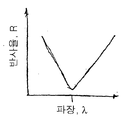
FIG. 17 is a graph showing the normalized intensity difference ΔI in% relative to the path length difference Δd for different materials from which optical elements may be constructed in optical elements, in particular immersion media.
본 발명에 의해 해결될 수 있는 문제점을 명확하게 하기 위하여, 도 1은 편광 빔 스플리터를 가진 카타디옵트릭 투사 대물렌즈(100)의 구성을 개략적으로 나타낸다. 이것은 물체 평면(101)에 배열된 레티클 등의 패턴을 축소된 스케일 예컨대 4:1의 비율로 이미지 평면(102)에 결상하는 기능을 하는데, 정확하게 한 개의 실 중간 이미지(미도시)를 생성한다. λ=157nm의 작동파장(operation wavelength)용으로 디자인된 투사 대물렌즈는 물체 평면과 이미지 평면 사이에 카타디옵트릭 제1대물렌즈부분(103)과 그 뒤의 순수 디옵트릭 제2대물렌즈부분(104)을 갖는다. 카타디옵트릭 대물렌즈부분은 광축에 대해 비스듬하게 기울어진 평평한 편광 빔 스플리터 면(107)을 가진 물리적 빔 스플리터(105)와, 또한 결상 오목 거울(108)을 가진 거울 그룹을 구비한다. 축소효과를 갖는 대물렌즈부분(104)은 광축에 대해 기울어진 평평한 편향 거울(110)을 갖는데, 편향 거울은 빔 스플리터 면(107)에서의 반사와 함께 물체 평면에 배열된 마스크가 이미지 평면(102)에 배열된 감광성 기판, 예컨대 포토리지스트 층으로 코팅된 반도체 웨이퍼를 향하도록 하는 것을 가능하게 한다. 이는 마스크와 웨이퍼의 스캐너 작동을 용이하게 한다. 편향 거울이 없는 실시예들 또는 하나 이상의 편향 거울을 갖는 변형예들 또한 물론 가능하다.In order to clarify the problem that can be solved by the present invention, FIG. 1 schematically shows the configuration of a catadioptric projection objective lens having a polarizing beam splitter. This functions to form a pattern of a reticle or the like arranged on the
(각 대물렌즈 영역들에서 선형으로 또는 원형으로 편광된) 편광된 자외선을 이용한 작동은 이러한 유형의 투사 대물렌즈의 특징인데, 편광 상태는 빔 스플리터 층(107)의 특성에 적합하게 된다. 편광-선택 빔 스플리터 층은 본질적으로 일 편광 방향을 투과시키고 다른 편광 방향을 블로킹한다. 이 경우, 편광 성분들(광학 소자 상의 입사 평면에 각각 수직이고 평행한 전기장 벡터의 성분들)의 롤(roll)은 빔 스플리터 층이 투과에서 사용되는지 또는 반사에서 사용되는지에 따라 바뀐다.Operation with polarized ultraviolet light (linearly or circularly polarized in each objective region) is a feature of this type of projection objective, the polarization state being adapted to the characteristics of the beam splitter layer 107. The polarization-selective beam splitter layer essentially transmits one polarization direction and blocks the other. In this case, the roll of polarization components (components of the electric field vector, each perpendicular and parallel to the plane of incidence on the optical element) changes depending on whether the beam splitter layer is used in transmission or reflection.
예시적인 시스템은 조명 시스템으로부터의 광이, 물체 평면(101)에 배열된 마스크 및 후속의 파지티브 렌즈(120)를 통과한 후, 편광 빔 스플리터(105)에 입사하기 전 최종에서 빔 스플리터 층(107)에 대해 s-편광되도록 디자인된다. s-편광된 광은 빔 스플리터 층(107)에 의해 오목 거울(108) 및 λ/4 판(121)을 통하는 경로를 향한 광 경로 상으로 편향되는데, λ/4판은 선편광된 광을 원편광된 광으로 변환하는데, 이는 다른 렌즈들(122, 123)을 통과한 후 오목 거울(108)에 입사한다. 상기 오목 거울로부터 반사된 광은 여전히 원편광된 광으로서 반대 방향으로 λ/4판(121)을 통과하여 선편광된 광으로 변환되기에 앞서 렌즈들(123, 122)을 통과하는데, 선편광된 광은 빔 스플리터 층(107)에 대해 이제 p-편광이다. p-편광된 광은 빔 스플리터 층(107)을 통과하여 편향 거울(110)에 입사하는데, 편향 거울은 광을 이미지 평면(102) 방향으로 편향시킨다. 그 방향의 경로 상에서 광은 복수개의 렌즈들(125, 127)을 통과하는데, 그 렌즈들 사이에 투사 대물렌즈의 이미지측 퓨필 면(126)이 위치한다.The exemplary system is characterized in that the beam splitter layer (in the last) after the light from the illumination system passes through the mask and subsequent
렌즈들과 편광 빔 스플리터의 모든 입사면들 및 출사면들은, 대물렌즈의 투과율을 개선하기 위하여 다층 유전체 반-반사 간섭층 시스템(AR 층)으로 덮여 있다. 거울들(108, 110)의 거울 면들은 고 반사성 유전체 반사 간섭층 시스템(HR 층)으로 덮여 있다.All entrance and exit surfaces of the lenses and polarizing beam splitter are covered with a multilayer dielectric anti-reflective interference layer system (AR layer) to improve the transmission of the objective lens. The mirror faces of the
이상적으로는, 설명된 편광 구분은 완벽하며 개개 광학 소자들에 입사하거나 그것들을 통과하는 광은 각각 이상적으로 소망된 바람직한 편광 방향을 갖는다. 그러나 투명 광학 소자들의 스트레스에 의해 유도된 및/또는 본질적인 이방성의 결과로서 및/또는 기하학적 효과의 결과로서, 각각 바람직하지 않은 편광 성분의 광 강도들 또한, 사용된 입사각의 방식에 의한 프로파일을 가진 간섭층 시스템의 편광-의존적인 효과의 결과로서 발생할 수 있다. 따라서, 필드 및 방향에 의존하는 상이한 크기를 갖는 바람직하지 않은 편광 성분 부분이 발생하는데, 그 부분은 빔 스플리터 층(107)에 의해 감쇄될 수 있다. 따라서 예컨대 이미지 평면(101)으로부터의 광의 p-부분은 통과될 수 있고 및/또는 오목거울로부터의 광의 s-부분은 반사될 수 있다. 이 "거절된" 강도 부분들은 그러면 바람직한 편광 성분의 강도에서 존재하지 않는다. 그 결과, 비록 물체 평면(101)에서의 레티클의 조명이 여전히 균일하더라도, 빔 스플리터 층 이전에서 강도 차이가 필드 지점 및 시스템의 출사 퓨필(126)에서의 이미지 좌표에 따라 관찰될 수 있다. 편의상 결상된 마스크 구조의 회절 패턴이 위치하는 퓨필(126)에 걸친 바람직한 국제적인 강도 분포를 기준 상태로 간주하는 것이 편리하다.Ideally, the polarization divisions described are perfect and the light entering or passing through the individual optical elements each has an ideally desired desired polarization direction. However, as a result of the stress of transparent optical elements and / or as a result of intrinsic anisotropy and / or as a result of geometric effects, respectively, the light intensities of the polarizing component, which are undesirable, also have interference with a profile by the manner of incidence angle used. Can occur as a result of the polarization-dependent effect of the layer system. Thus, undesirable portions of polarization components with different magnitudes depending on the field and direction occur, which may be attenuated by the beam splitter layer 107. Thus, for example, the p-portion of light from the
나란히 놓인 부분 그림은 빔 스플리터 층(107)의 구체적인 층의 영향 하의 축상 지점의 출사 퓨필(126)에서의 공간적인 강도 분포를 개략적으로 보여준다. 이 경우, 조명 강도는 더 낮은 선 밀도를 갖는 영역보다 선들이 서로 더 밀접하여 위치한 영역에서 더 높다. 따라서 출사 퓨필에서 위치-의존적인 어두워짐이 존재하는데, 이는 결상 중 최소 배선폭의 바람직하지 않은 변동을 가져올 수 있다.The side-by-side partial view schematically shows the spatial intensity distribution in the
문제점들은, 적절한 위치에서 투사 대물렌즈에 존재하는 적어도 하나의 간섭층 시스템(AR 층 또는 HR 층)의 반사 효과 또는 반사-감소 효과의 효과를 감손(impairment)시키는 본 발명에 따라, 시스템의 공간적 강도 변동의 부분적인 또는 완전한 보상이 기능성 층의 광학 효율의 상대적으로 큰 공간적 변동을 이용하여 달성되도록 함으로써, 줄어들게 하거나 회피되도록 할 수 있다.Problems are, in accordance with the present invention, which impairs the effect of the reflection effect or the reflection-reduction effect of at least one interfering layer system (AR layer or HR layer) present in the projection objective lens at the proper position, according to the invention. Partial or complete compensation of the variation can be achieved by using a relatively large spatial variation in the optical efficiency of the functional layer, thereby reducing or avoiding it.
도 2 및 도 3을 참조하여, 먼저 거울 층의 반사 효과의 국지적인 "감손"을 통해 어떻게 강도 분포가 더욱 균일하게 될 수 있는지에 대해 설명한다. 오목 거울(108) 상에 피팅된 고 반사성 다층 간섭층 시스템(200)이 이 목적을 위해 예시적으로 고려된다. 이 HR 층은 특히 소망된 아포다이즈화에 매우 적합한데, 중간 이미지를 갖는 예시적인 시스템에서 출사 퓨필(126)에 대해 광학적 켤레(conjugate) 퓨필 면이 오목 거울(108) 상에 또는 그 인근에 배열되도록 디자인되기 때문이다. 따라서 출사 퓨필의 강도 분포는 거울 층(200)의 반사율의 공간적 변조에 의해 영향받을 수 있다. 아포다이즈화를 위한 이 거울 층의 선택은 또한 바람직한데, 방사의 상대적으로 매우 작은 입사각만이 오목 거울(108)에서 일어나기 때문이며, 이는 우수한 반사 효과를 가진 상대적으로 단순한 층 디자인을 허용한다.With reference to FIGS. 2 and 3, how the intensity distribution can be made more uniform is first described through the local "damping" of the reflection effect of the mirror layer. Highly reflective multilayer
상기 거울 층을 위해 소위 λ/4 디자인이 사용될 수 있는데, 이 디자인은 고굴절율과 저굴절율을 교번하여 갖는 유전체층을 이용하며, 층 두께 d는 nH·dH=nL·dL=(λ/4±10%)의 조건을 만족해야 한다. 여기서 첨자 H, L은 고굴절율을 갖는 유전체 물질과 저굴절율을 갖는 유전체 물질을 의미하며, n은 물질의 굴절율이고 d는 기하학적 층 두께이다. λ는 시스템의 작동파장으로 예컨대 157nm이다. 유전체 HR 층 시스템용의 층 차례(layer sequence)는 기판 상에 직접 형성된 고굴절율을 갖는 층으로 시작할 수 있는데, 저굴절율을 갖는 층과 고굴절율을 갖는 층을 구비한 N 쌍들이 그 층 상에 그 후 배열된다(표시: S|H(LH)N).A so-called λ / 4 design can be used for the mirror layer, which uses a dielectric layer having alternating high and low refractive indexes, the layer thickness d being n H · d H = n L · d L = (λ / 4 ± 10%) must be satisfied. Where the subscripts H and L refer to dielectric materials having a high refractive index and dielectric materials having a low refractive index, n is the refractive index of the material and d is the geometric layer thickness. λ is the operating wavelength of the system, for example 157 nm. The layer sequence for the dielectric HR layer system may begin with a layer having a high refractive index formed directly on the substrate, with N pairs having a low refractive index layer and a high refractive index layer on the layer. Then arranged (indicated by S | H (LH) N ).
고려대상이 된 층 물질들의 예는 고굴절율을 갖는 층 용으로 란탄늄 플루오라이드(LaF3)와 저굴절율을 갖는 층 용으로 마그네슘 플루오라이드(MgF2)를 들 수 있다. 대안으로서 고굴절율을 갖는 물질로서 가돌리늄 플루오라이드(GdF3), 지르코늄 플루오라이드(ZrF4), 하프늄 플루오라이드(HfF4), 홀미윰 플루오라이드(HoF3), 에르븀 플루오라이드(ErF3), 이테르븀 플루오라이드(YbF3) 또는 이트륨 플루오라이드(YF3) 또한 적절할 수 있다. 저굴절율을 갖는 대안 물질들은 주로 키올라이드(chiolite), 크리올라이드(kryolite), 알루미늄 플루오라이드(AlF3), 소듐 플루오라이드(NaF), 리튬 플루오라이드(LiF) 또는 바륨 플루오라이드(BaF2)이다.Examples of layer materials under consideration include lanthanum fluoride (LaF 3 ) for layers with high refractive index and magnesium fluoride (MgF 2 ) for layers with low refractive index. Alternatively gadolinium fluoride (GdF 3 ), zirconium fluoride (ZrF 4 ), hafnium fluoride (HfF 4 ), holmium fluoride (HoF 3 ), erbium fluoride (ErF 3 ), ytterbium Fluoride (YbF 3 ) or yttrium fluoride (YF 3 ) may also be suitable. Alternative materials with low refractive index are mainly chiolite, kryolite, aluminum fluoride (AlF 3 ), sodium fluoride (NaF), lithium fluoride (LiF) or barium fluoride (BaF 2 ) to be.
모든 개개 층들의 층 두께를 몇 퍼센트 정도 감소시켜 그 영역들에서 더 낮은 반사율을 갖도록 함으로써, 예견된 위치에서의 반사 효율의 감손을 달성하는 것이 가능하다. 설명을 명확하게 하기 위하여, 도 2는 31개의 λ/4 층을 구비한 층 스택의 반사율 R의 스펙트럼 프로파일(실선)과 모든 개개 층들의 층 두께가 명목상의 층 두께에 비해 대략 7% 감소된 디자인의 프로파일(점선)을 보여준다. 이 전체적인 층 두께 감손이 스펙트럼 프로파일이 더 짧은 파장으로 반대-튜닝(detuning)하는 것에 이르게 한다는 것이 명백한데, 예에서 작동 파장 157nm로부터 대략 149nm의 더 낮은 파장으로 반사 최고값(대략 95%의 절대값)이 쉬프팅했다. 따라서 157nm의 작동 파장에서의 반사율이 이론적으로 λ/4와 λ/4·0.93 사이의, 대략 95% (157nm에서 λ/4 디자인의 최대값)과 10% (157nm에서 λ/4·0.93 디자인의 반사율) 이하 사이의 층 두께 프로파일 변동에 의해 변할 수 있다. 이 더 낮은 반사율은 높은 파장측 상에서 기본 최대(primary maximum) 옆의 제1최소에서 λ/4 디자인의 값에 대응한다. 따라서 층 두께의 "반대-튜닝(detuning)"은 반사율의 국지적인 변조에서 매우 큰 변조 변동(very large modulation swing)을 가능하게 한다.
By reducing the layer thickness of all individual layers by a few percent to have lower reflectivity in those regions, it is possible to achieve a loss of reflection efficiency at the foreseen position. For clarity, FIG. 2 is a design in which the spectral profile (solid line) of the reflectance R of a layer stack having 31 λ / 4 layers and the layer thickness of all individual layers are approximately 7% reduced compared to the nominal layer thickness. Shows the profile (dotted line). It is evident that this overall layer thickness loss leads to the detuning of the spectral profile to shorter wavelengths, in this example the reflection maximum (approximately 95% absolute) from the operating wavelength of 157 nm to a lower wavelength of approximately 149 nm. ) Shifted. Thus, the reflectance at an operating wavelength of 157 nm is theoretically approximately 95% (maximum value of λ / 4 design at 157 nm) and 10% (λ / 4 · 0.93 design at 157 nm) between λ / 4 and λ / 4 · 0.93. Reflectivity) can be varied by varying the layer thickness profile between or below. This lower reflectance corresponds to the value of the λ / 4 design at the first minimum next to the primary maximum on the high wavelength side. Thus "detuning" the layer thickness allows for a very large modulation swing in the local modulation of the reflectance.
*설명된 바와 같은 방식으로, 예컨대 코팅 제조에 있어서 칸막이판 법을 이용하여 코팅된 광학 소자의 중심으로부터 가장자리로 층 두께를 감소시키는 것이 이론적으로 가능할지라도, 대부분의 표준적인 코팅법에서의 제조 변동은 모든 개개 층의 두께가 코팅에서 코팅에 따라 대략 1% 내지 3% 정도 변하는 효과를 갖는다. 그러나 반사 또는 반사율이 기본 최대의 가장자리에서 매우 급격하게 감소하기 때문에, 제조 변동을 고려할 때는 대략 10%와 대략 30% 사이의 크기로 실제로 얻어지는 반사율에서의 큰 변화를 고려할 필요가 있다. 그 결과, 강도 변동의 보상을 허용할 충분히 정확하게 정의된 값으로 모든 개개 층의 특정한 층 두께 프로파일을 제조함으로써, 거울의 전체 이용가능한 영역에 걸쳐 간섭층 시스템의 반사율을 세팅하는 것이 어려워진다.* Although it is theoretically possible to reduce the layer thickness from the center to the edge of the coated optical element in the manner as described, for example in the manufacture of coatings using the partition plate method, the manufacturing variations in most standard coating methods are The thickness of all individual layers has the effect of varying approximately 1% to 3% depending on the coating in the coating. However, since the reflection or reflectance decreases very sharply at the edge of the base maximum, it is necessary to take into account the large change in reflectance actually obtained with magnitudes between approximately 10% and approximately 30% when considering manufacturing variations. As a result, it is difficult to set the reflectance of the interfering layer system over the entire available area of the mirror by making a particular layer thickness profile of all individual layers to a sufficiently precisely defined value that will allow compensation of the intensity variation.
바람직한 일 실시예에 있어서, 거울의 국지적인 반사율에 있어서 상당히 더 낮은 변동, 따라서 강도 변동의 더욱 정밀한 보상이 가능하다. 이는 도 3을 참조하여 더욱 상세히 설명된다. 출발점은 다시 S|H(LH)N 유형의 HR 층 시스템이다. 입사광 방향에서 최종 층(최외곽 층)은 일반적으로 고굴절율을 갖는 층이다. 만일 저굴절율의 층이 상기 층에 부가적으로 형성된다면, 이는 층 결합체(layer assembly)의 반사 효과를 감소시킨다. 통상적으로 얻을 수 있는 변조 크기는 도 2를 참조하여 설명하는데, 이는 최상 층의 층 두께의 함수로서 λ/4 층을 구비하는 HR 층 스택의 반사율을 보여준다. 초기 층 시스템은 31개의 λ/4 층들을 갖는데, 이 경우 고굴절율의 물질은 nH=1.79의 굴절율을 가지며 저굴절율의 물질은 nH=1.45의 굴절율을 갖는다. 기판에 인접한 층은 고굴절율을 갖는다. 만일 최상 층이 고굴절율 물질의 λ/4층이라면, R=95.2%의 최대 반사율을 달성한다. 만일 최상부 H 층의 두께가 λ/4로부터 0으로 점진적으로 감소한다면, 반사율은 연속적으로 감소한다. 이는 도 2에서 31개 층과 30개 층 사이에 대응한다. 만일 저굴절율의 물질로 된 부가적인 층이 31번째 H 층 상에 형성된다면, 저굴절율 층의 층 두께가 λ/4에 이를 때까지 마찬가지로 연속적으로 감소한다. 이는 31개 층과 32개 층 사이 영역에 도 2에 도시되어 있다. 최상부 H층의 두께를 줄임으로써 또는 저굴절율 물질로 된 층을 추가적으로 부가함으로써, 이 예시적인 시스템에서 반사율을 대략 95.2%와 86.6% 또는 87.9% 사이에서 변화시키는 것이 가능하다. 변조 크기는 따라서 대략 10%에 한정되는데, 이는 동시에 절대값으로 달성될 수 있는 최대 반사율의 대략 10%에 대응한다. 그러나 이 변조 크기 내에서, 심지어 제조 조건 하에서 통상적인 층 두께 변동을 고려할 때에도 아무런 문제점 없이 임의의 반사율이 작은 변동 범위(통상적으로 1% 내지 3%)를 가지면서 세팅될 수 있다.In one preferred embodiment, a significantly lower variation in the local reflectance of the mirror, thus more precise compensation of the intensity variation is possible. This is explained in more detail with reference to FIG. 3. The starting point is again HR layer system of type S | H (LH) N. The final layer (outermost layer) in the incident light direction is generally a layer having a high refractive index. If a low refractive index layer is additionally formed on the layer, this reduces the reflection effect of the layer assembly. A typical obtainable modulation size is described with reference to FIG. 2, which shows the reflectance of the HR layer stack with λ / 4 layer as a function of the layer thickness of the top layer. The initial layer system has 31 λ / 4 layers, in which the high refractive index material has a refractive index of n H = 1.79 and the low refractive index material has a refractive index of n H = 1.45. The layer adjacent to the substrate has a high refractive index. If the top layer is a λ / 4 layer of high refractive index material, a maximum reflectance of R = 95.2% is achieved. If the thickness of the top H layer gradually decreases from λ / 4 to zero, the reflectance decreases continuously. This corresponds between 31 and 30 layers in FIG. 2. If an additional layer of low refractive index material is formed on the 31st H layer, it is likewise continuously reduced until the layer thickness of the low refractive index layer reaches λ / 4. This is shown in FIG. 2 in the region between the 31 and 32 layers. By reducing the thickness of the top H layer or by additionally adding a layer of low refractive index material, it is possible to change the reflectance between approximately 95.2% and 86.6% or 87.9% in this exemplary system. The modulation magnitude is therefore limited to approximately 10%, which at the same time corresponds to approximately 10% of the maximum reflectance that can be achieved with absolute values. However, within this modulation magnitude, any reflectance can be set with a small variation range (typically 1% to 3%) without any problem, even when considering typical layer thickness variations under manufacturing conditions.
회전대칭 및 비-회전대칭 공간 층 두께 분포 또는 반사율 등급을 만드는 다양한 가능성들을 이하에서 설명한다.Various possibilities for creating rotationally and non-rotationally symmetric spatial layer thickness distributions or reflectance grades are described below.
반-반사 층(AR 층)의 경우, 우수한 절대 정확도로 광학 소자의 반사율 및/또는 투과율의 큰 공간적 변조를 만드는 다양한 방법들이 있다. 알려진 바와 같이, 유전체 간섭층 시스템의 최적 반-반사 효과는 다소 넓은 층 두께 범위, 예컨대 모든 층 두께를 λ/4±10%로 세팅함으로써만 달성될 수 있다. 이 경우, 반사율 최소의 스펙트럼 폭이 명목상으로 층 쌍(layer pairs)의 개수에 따라 증가한다는 것을 더 고려해야만 한다. 명확한 설명을 위해, 도 4a는 많은 층 쌍들을 갖는 반-반사 층 시스템의 반사율 R 스펙트럼 프로파일을 개략적으로 나타내며 도 4b는 몇몇 개개 층들을 갖는 반-반사 층 시스템의 반사율 R 스펙트럼 프로파일을 개략적으로 나타내는데, 각각의 경우 S|H (HL)N의 기본적인 구성을 갖는다. 이 경우, 고굴절율 물질과 저굴절율 물질로 형성된 많은 층 쌍들이 저굴절율을 갖는 최하 층 상에 배열될 때(통상적으로 N>1), 넓은 반사 최소가 달성된다(도 4a). 반대로 만일 오직 세 개의 층들이 사용된다면(N=1), 작동 파장 λ에서 좁은 반사 최소의 결과, 다소 더 크고 더 작은 파장을 향해 선형으로 다소 명확하게 증가하는 반사율 결과가 된다. 그러한 특성을 갖는 코팅을 여기서 V-코팅이라 한다(도 4b).In the case of a semi-reflective layer (AR layer), there are various ways of creating large spatial modulation of the reflectance and / or transmittance of the optical element with good absolute accuracy. As is known, the optimal anti-reflective effect of the dielectric interference layer system can only be achieved by setting a rather wide layer thickness range, such as all layer thicknesses to [lambda] / 4 ± 10%. In this case, further consideration must be taken that the spectral width of the reflectance minimum nominally increases with the number of layer pairs. For clarity, FIG. 4A schematically shows a reflectance R spectral profile of a semi-reflective layer system with many layer pairs and FIG. 4B schematically shows a reflectance R spectral profile of a semi-reflective layer system with several individual layers, In each case it has the basic configuration of S | H (HL) N. In this case, when many layer pairs formed of high and low refractive index materials are arranged on the lowest layer with low refractive index (typically N> 1), a broad reflection minimum is achieved (FIG. 4A). On the contrary, if only three layers are used (N = 1), the result is a narrow reflection minimum at the operating wavelength λ, resulting in a somewhat clear increase in linearity towards a somewhat larger and smaller wavelength. Coatings having such properties are referred to herein as V-coatings (FIG. 4B).
만일 층 시스템의 모든 개개 층들이 명목상의 층 두께보다 상당히 더 두껍거나 더 얇게 만들어진다면, V-코팅에서 반사율 최소는 더 짧은 파장으로 이동하는데, 반면 작동 파장 λ에서 반사율은 층 두께 반대-튜닝에 따라 급격하게 상승한다. 도 5는 이러한 점을 보여주는데, 실선은 3층 λ/4 층 시스템의 경우 반사율의 스펙트럼 프로파일을 나타내고 점선은 모든 개개 층이 대략 30%-40% 더 작아진 층 두께를 갖는 층 시스템의 경우에 단파장 방향으로 쉬프팅된 것을 보여준다. 명목상의 층 두께(예컨대 λ/4)에 대한 두께 변화(%로 나타내짐)의 경우 반-반사 코팅의 반사율 의존성이 예시로서 도 6에 도시되어 있다. 이 경우, 30%의 두께에서의 상대적인 변화는 잔여 반사율을 0.3%에서 대략 4.8%로 증가시키는 결과를 초래하였는데, 이는 투명한 기판의 잔여 반사 Rsub의 영역에 위치한다. 만일 도 6에 도시된 것과 같은 유형의 그래프가 주어진 층 시스템에 대해 최초 기록된다면, V-코팅의 개개 층의 층 두께의 국지적인 변화에 의해, 잔여 반사율의 최대 달성가능한 변조에 있어서(변조 크기 대략 8%), 잔여 반사의 임의의 소망된 공간적 변조를 세팅하는 것이 가능하다. 이는, 각각의 경우 고려된 광학 소자의 장착 상태에서 상대적으로 높은 강도가 발생하는 영역에서만 반-반사 층의 반대-튜닝을 층 두께 변경을 통해 세팅하는 것을 포함하는데, 이에 따라 강도 분포는 광학 소자를 통과한 후 더욱 균일해질 수 있다.If all individual layers of the layer system are made significantly thicker or thinner than the nominal layer thickness, the reflectance minimum in the V-coating shifts to a shorter wavelength, while at the operating wavelength λ the reflectance depends on layer thickness counter-tuning. Rises sharply. Fig. 5 shows this point, with the solid line showing the spectral profile of the reflectivity for the three layer λ / 4 layer system and the dotted line for the short wavelength for the layer system where all individual layers have approximately 30% -40% smaller layer thickness. Show shifted in direction. The reflectance dependence of the anti-reflective coating for the change in thickness (expressed in%) relative to the nominal layer thickness (eg λ / 4) is shown in FIG. 6 by way of example. In this case, the relative change in thickness of 30% resulted in increasing the residual reflectivity from 0.3% to approximately 4.8%, which is located in the region of the residual reflection R sub of the transparent substrate. If a graph of the type as shown in FIG. 6 is initially recorded for a given layer system, by local variation in the layer thickness of the individual layers of the V-coating, the maximum achievable modulation of the residual reflectance (modulation magnitude approx. 8%), it is possible to set any desired spatial modulation of the residual reflection. This involves in each case setting the anti-tuning of the anti-reflective layer via a layer thickness change only in areas where relatively high intensity occurs in the mounting state of the optical element under consideration, whereby the intensity distribution is dependent upon the optical element. After passing it can be more uniform.
모든 층들의 두께에서의 설명된 변화에 대한 대안으로서, 반-반사 간섭층 시스템의 경우 오직 한 개별 층, 예컨대 최외곽 층의 층 두께를 적합하게 세팅함으로서 큰 변조로 잔여 반사율의 소망된 프로파일을 달성하는 것이 가능하다.As an alternative to the described change in the thickness of all layers, in the case of a semi-reflective interference layer system a suitable modulation of the layer thickness of only one individual layer, for example the outermost layer, is achieved with large modulation to achieve the desired profile of residual reflectivity. It is possible to.
렌즈 또는 거울 상에서의 두 개의 가능한 층 두께 분포가 예시적인 목적으로 도 7에 도시되어 있는데, 상대적인 층 두께는 휘도값으로 표현되어 있다. 도 7a는 층 두께가 원형 영역의 중앙으로부터 가장자리로 갈수록 연속적으로 증가하는 회전대칭 층 두께 분포를 나타낸다. 도 7b는 층 두께가 중앙에서 더 얇은 6-폴드 회전대칭을 가진 층 두께 분포를 나타내는데, 별모양 영역은 주위의 더 밝은 영역에서보다 어둡게 나타난다.Two possible layer thickness distributions on a lens or mirror are shown in FIG. 7 for illustrative purposes, where the relative layer thicknesses are represented by luminance values. 7A shows a rotationally symmetric layer thickness distribution in which the layer thickness increases continuously from the center to the edge of the circular area. FIG. 7B shows the layer thickness distribution with 6-fold rotational symmetry where the layer thickness is thinner at the center, where the star region appears darker than in the brighter surroundings.
보여진 층 두께 분포 또는 대응하는 투과율 또는 반사율의 공간적인 분포에 이르게 하는 다른 공간적 층 두께 분포는, 바깥쪽 층의 층 두께가 매우 변하도록 이온 조사에 의해 바깥쪽 층을 국지적으로 제거함에 있어서, 균일한 층 두께, 예컨대 λ/4 층을 가진 주어진 층 시스템의 경우로 이루어진다. 그 결과, 예컨대 도 3을 참조하여 설명한 효과를 이용하는 반면 거울 층 상에서 매우 큰 변조 크기로 반사율의 변동을 생성하는 것이 가능하다.The layer thickness distribution shown or other spatial layer thickness distributions leading to the corresponding spatial distribution of transmittance or reflectance is uniform in the local removal of the outer layer by ion irradiation such that the layer thickness of the outer layer varies significantly. In the case of a given layer system with a layer thickness, for example λ / 4 layer. As a result, it is possible to produce variations in reflectance with very large modulation magnitudes on the mirror layer, for example, while using the effect described with reference to FIG. 3.
반-반사 층의 경우, 모든 층들의 두께를 변화시킴으로써(도 5 및 도 6 참조) 또는 오직 선택된 층 특히 최외곽 층만의 두께를 변화시킴으로써(도 3 및 관련된 설명 부분 참조) 반사에서의 증가(또는 투과율 감소)를 달성할 수 있는 가능성이 있다. 모든 두께들을 변화시키는 것은 예컨대 렌즈의 코팅에서 대응하는 계산된 칸막이판 배열을 이용함으로써 달성될 수 있는데, 칸막이판 배열은 형성되는 층 두께를 대략 균일하게 감소시킨다. 만일 오직 한 개의 층 두께만이 변화된다면, 층 두께의 공간적 변화를 달성하기 위하여, 이는 칸막이판들 없이 또는 특정 층 두께 및 층 두께 분포에 대응하는 제1칸막이판들의 세트로 한 개 또는 그 이상의 개개 층들을 먼저 코팅하고 그 후 최종 층의 제조에 앞서 상이한 칸막이판들의 세트를 이용함으로써 달성될 수 있다.In the case of a semi-reflective layer, the increase in reflection (or by changing the thickness of all layers (see FIGS. 5 and 6) or only the selected layer, especially the outermost layer (see FIG. 3 and related description), or Decrease in transmittance). Changing all the thicknesses can be achieved, for example, by using a corresponding calculated partition plate arrangement in the coating of the lens, which partition plate thickness reduces approximately uniformly. If only one layer thickness is changed, in order to achieve a spatial change in the layer thickness, one or more of the individual partition plates may be used without partition plates or with a set of first partition plates corresponding to a particular layer thickness and layer thickness distribution. By coating the layers first and then using a different set of partition plates prior to the preparation of the final layer.
행성형 시스템(planetary system)을 가진 코팅 장치의 도움으로 특정 층 두께 프로파일을 달성할 수 있는 두 가지 가능성을 도 8 및 도 9를 참조하여 설명한다. 행성형 시스템은 주 캐리어(principal carrier)(행성형 캐리어)(미도시)를 갖는데, 이는 주 회전축(80, 90)을 중심으로 회전될 수 있다. 이 예의 경우, 네 개의 기판 캐리어(기판 플래니트, substrate planet)들이 행성형 캐리어 외측에 배열되어 있으며, 각각의 경우 기판을 각각 렌즈(81, 91)의 형태로 코팅되도록 운반한다. 기판 캐리어들은 주 회전축에 평행하게 연장되는 각각의 기판 캐리어 축을 중심으로 회전될 수 있어서, 기판들은 주 회전축을 중심으로 전체적인 회전을 할 수 있으며 주 행성형 캐리어와 플래니트(planet)들의 회전에 따라 그것들의 기판 캐리어 축들(82, 92)을 중심으로 본질적인 회전을 할 수 있다. 플래니트들은 증발 소스(미도시) 상부에 배열되고 기판들은 행성들의 하측에 고정되어, 코팅될 측이 물질 소스를 향하도록 한다. 플래니트들 하부의 소수의 칸막이판들(83, 93)이 물질 소스와 플래니트들 사이에 위치해 있으며, 플래니트들의 이동 중 때때로 증발 물질로부터의 물질 증기를 셰이딩하고, 각각의 셰이딩 시간을 결정하는 플래니트들의 회전 시간에 따라 칸막이판은 형성하는데, 이는 다시 증착되는 층 두께를 결정한다.Two possibilities for achieving a specific layer thickness profile with the aid of a coating apparatus with a planetary system are described with reference to FIGS. 8 and 9. The planetary system has a principal carrier (planetary carrier) (not shown), which can be rotated about the main axes of
도 8에 따른 실시예에서, 각각의 경우 칸막이판(83)은 타원형 형상이며 본질적으로 플래니트들의 회전축이 코팅면을 관통하는 지점과 물질 소스 사이를 연결하는 선을 중심으로 중심에 위치한 방식으로 배열되어, 코팅될 기판의 중심 영역이 더 긴 시간 동안 셰이딩되도록 한다. 예에서, 칸막이판 형상은 기판 축(82)에 대해 회전대칭인 층 두께 프로파일이 형성되는 것을 보장하는데, 이 경우 코팅(84)의 층 두께는 기판의 중심으로부터 가장자리 방향으로 연속적으로 예컨대 대략 포물선 형상으로 증가한다. 무엇보다도 만일 반사 코팅 형성 중 복수개의 층들이 형성되어 실질적으로 균일한 층 두께를 형성한다면, 그리고 만일 그 후 최외곽 층이 전술한 방식으로 이어 형성된다면, 기판의 중심과 가장자리에서 적절한 선택의 층 두께로 주어진 거울이 제조될 수 있으며, 그 거울의 반사율은 그 광축의 영역에서보다 가장자리에서 훨씬 더 작거나 크다(도 3 참조).In the embodiment according to FIG. 8, in each case the
도 9에 따른 실시예에서, 주 회전축(90)에 대해 실질적으로 방사상으로 연장된 칸막이판(93)을 사용한다. 이 경우, 행성형 캐리어의 회전 및 플래니트들 또는 기판들의 회전은, 코팅될 기판이 칸막이판(93)에 의해 부분적으로 덮일 때는 언제나 기판이 코팅될 경우 특정 영역(영역 B)은 주 회전축을 향하며 반대 영역(A)은 외측에 위치하도록, 칸막이판들의 위치에 대해 조정된다. 이와 대비하여 만일 기판들이 전체 물질 증기 내에서 칸막이판들 사이에 위치한다면, 각각의 경우 면 영역(B)은 외측으로 방사상으로 위치하며 반면 면 영역(A)은 주 회전축에 더 가깝게 위치하여 따라서 평균적으로 더 큰 증기 증착율로 코팅된다. 이러한 구성으로, 코팅 공정 중 실질적으로 더 많은 코팅 물질이 렌즈 영역(A)에 반대 렌즈 영역(B)에보다 증착되는데 이는 더 많은 증착율로 코팅될 때 항상 영역(B)가 셰이딩되며, 반면 셰이딩 칸막이판들 사이의 상태에서는 증막 소스로부터 더 먼 거리에 위치하기 때문에 반대 영역(A)보다 더 적은 증기 증착 물질로 코팅되기 때문이다. 이러한 방식으로 기판(91)의 단면에 걸쳐 영역(A)에서 더 큰 층 두께로부터 영역(B)에서 더 낮은 층 두께를 갖는 연속적인 층 프로파일을 갖는 코팅(94)을 형성하는 것이 가능하다. 이 기술은 예컨대 λ/4 스택의 외곽 층 형성시에만 사용될 수 있다.In the embodiment according to FIG. 9, a
이러한 기본 원리를 이용하여, 주 회전운동을 하는 캐리어 및 플래니트들 사이에 위치한 기어 메커니즘의 투과율을 적합한 적합화를 통해 다른 대칭의 코팅을 세팅하는 것 역시 가능한데, 예컨대 3-폴드, 4-폴드 또는 6-폴드 방사상 대칭의 코팅을 세팅하는 것이 가능하다(도 7b 참조).Using this basic principle, it is also possible to set up coatings of different symmetry through suitable adaptation of the transmission of the gear mechanism located between the carriers and the planets making the main rotational movement, for example 3-fold, 4-fold or It is possible to set up a six-fold radially symmetric coating (see FIG. 7B).
이러한 몇몇 예들에 기초하여, 당업자라면 알려진 아포다이즈화 기술을 적합한 방식으로 변형하여 실질적으로 임의의 회전 대칭 또는 비회전대칭 층 두께 분포를 갖는 반사 코팅 또는 반-반사 코팅을 형성하는 것이 가능하다.Based on some of these examples, it is possible for a person skilled in the art to modify known apodizing techniques in a suitable manner to form reflective or anti-reflective coatings having substantially any rotationally symmetric or non-rotationally symmetric layer thickness distribution.
이하의 실시예들에서는 특히 액침 시스템에서 콘트라스트를 개선하는 것과 관련된 것을 설명한다. 광학적으로 효과적인 흡수성 요소들을 이용하여 필드-의존적이며 퓨필-의존적인 투과율 분포를 보상하는 것을, 특히 고체 액침 매질 또는 액체 액침 매질의 경우에 있어서 예시적으로 설명한다.The following embodiments describe what is particularly related to improving contrast in immersion systems. Compensating the field-dependent and pupil-dependent transmittance distribution using optically effective absorbent elements is illustrated by way of example, particularly in the case of solid immersion media or liquid immersion media.
바람직한 응용예에서, 본 발명의 이러한 특징은 액침 리소그래피용 투사 노광 장치에서 구현된다. 도 10은 투사 노광 장치(1110)를 개략적으로 나타내는데, 이는 조명 시스템(1112)과, 물체 평면(1122)과, 투사 대물렌즈(1120)와, 이미지 평면(1128)과, 보상 요소(L1)와, 외부로부터의 광을 스크린하기 위한 산란된 광 칸막이판(L2')을 구비한다. 조명 시스템(1112)은 보상 요소(1116'', L1)를 가진 제2투사 대물렌즈(1116)와 열 발산 소자(1116')를 포함한다.In a preferred application, this feature of the invention is implemented in a projection exposure apparatus for immersion lithography. 10 schematically shows a
전술한 최종 강도 콘트라스트와 그것의 퓨필 및 필드 효과는 투사 노광 장치와 관련된 투사 대물렌즈의 이미지 필드에서 퓨필 및 필드 프로파일들을 두 번 계산함으로써 결정되는데, 제1계산에서는 액침 매질이 변하지 않은 채 이루어지고 제2계산에서는 액침 매질이 가상의 매질로 바뀌는데, 이는 투과율 성향은 별논으로 하고 액침 매질과 동일한 광학적 특성을 가지나 흡수율 α=0이다. 이는 투사 대물렌즈의 기하학적 형상과, 물체 필드의 필드 사이즈와, 이미지측 개구수와, 액침 매질의 흡수율 α를 따르는 퓨필 및 필드 효과의 의존성의 결과를 가져온다.The above-described final intensity contrast and its pupil and field effects are determined by calculating the pupil and field profiles twice in the image field of the projection objective associated with the projection exposure apparatus, in which the immersion medium is left unchanged and In the second calculation, the immersion medium is changed into a imaginary medium, which has the same propensity as the immersion medium and has the same optical properties as the immersion medium, but has an absorption coefficient of α = 0. This results in the dependence of the geometry of the projection objective, the field size of the object field, the image-side numerical aperture, and the pupil and field effects along the absorption coefficient α of the immersion medium.
원자외선(DUV) 및 진공자외선(VUV)파장 λ에서, 특히 λ=248, 193 또는 157 나노미터에서, 리소그래피에서 특히 사용되듯이, 많은 투명 액침 매질은 0이 아닌 흡수율 α를 갖는데, 특히 α>0.03cm-1이 발생한다.At the far ultraviolet (DUV) and vacuum ultraviolet (VUV) wavelengths λ, in particular at λ = 248, 193 or 157 nanometers, as is particularly used in lithography, many transparent immersion media have non-absorbance α, in particular α> 0.03 cm -1 occurs.
근거리 필드 리소그래피에서, 고체가 액침 매질로서 사용되며 이는 고굴절율 n을 갖는데, 특히 n>1.6 또는 n>1.8 또는 심지어 n>1.9이다. 이들은 동등하게 예컨대 스피넬(spinell), 사파이어 등으로 만들어진 렌즈들 또는 최종 플레이트로 구비된다.In near field lithography, a solid is used as the immersion medium, which has a high refractive index n, in particular n> 1.6 or n> 1.8 or even n> 1.9. These are equivalently provided with lenses or final plates made of, for example, spinel, sapphire or the like.
이 물질들의 본질적인 흡수율은 유사하게 석영 글래스 또는 CaF2와 같은 상업적으로 이용가능한 물질들보다 더 높다.The intrinsic absorption of these materials is similarly higher than those of commercially available materials such as quartz glass or CaF 2 .
이 경우, 근거리 필드는 파장 λ의 네 배보다 작은 동작거리(working distance) 또는 심지어 파장 λ보다 작은 동작거리를 의미하는 것으로 이해된다. 이 경우, 동작거리는 투사 대물렌즈의 이미지 평면으로부터 투사 대물렌즈의 이미지 평면 이전의 최종 광학 요소까지의 거리이다.In this case, the near field is understood to mean a working distance less than four times the wavelength [lambda] or even a working distance less than the wavelength [lambda]. In this case, the working distance is the distance from the image plane of the projection objective lens to the final optical element before the image plane of the projection objective lens.
아래와 같은 흡수법칙Absorption Law
T(L)=e-αL T (L) = e -αL
에 따라, 투과된 강도는 흡수율 α 및 횡단된 거리 L에 따라 지수적으로 감소한다. 이는 필드 위치에 따라 퓨필에 걸쳐 균일하지 않은 투과율의 결과를 가져온다.As a result, the transmitted intensity decreases exponentially with the absorption rate α and the traversed distance L. This results in non-uniform transmittance across the pupil, depending on the field position.
평평한 계면들 사이에서, 광학적 거리는 물질 내에서의 전파 각도에 따라 코사인곡선 형상으로 증가하는데, 텔레센트릭 결상의 경우 어떠한 필드 변화도 발생하지 않는다. 이 사실은 도 10a로부터 추론할 수 있다.Between flat interfaces, the optical distance increases in cosine shape with the angle of propagation in the material, with no field change occurring in the case of telecentric imaging. This fact can be deduced from FIG. 10A.
만일 액침 매질 상부에 위치한 광학 요소의 하측이 곡선이라면, 관련된 것은 굴절력 특히 파지티브 굴절력을 갖는 액침 렌즈, 특히 액체 렌즈이다. 필드 의존성은 도 10b와 같이 명백하다.If the lower side of the optical element located above the immersion medium is curved, the relevant one is an immersion lens, in particular a liquid lens, having refractive power, in particular positive refractive power. Field dependencies are apparent as in FIG. 10B.
이 문제 영역을 설명하는 다른 가능성들은 다음과 같이 설명된다.Other possibilities for describing this problem area are described as follows.
리소그래피 대물렌즈에서와 같이 큰 필드 크기를 가진 고-개구(high-aperture) 시스템에서, 고체 물질로 만들어진 또는 유체 특히 액체로 만들어진 광학적 효과 렌즈들에서 큰 경로 길이 차들이 발생한다.In high-aperture systems with large field sizes, such as in lithographic objectives, large path length differences occur in optical effect lenses made of solid materials or fluids, especially liquids.
도 16의 예는 상부 개구 광선(UCR; upper coma ray = upper aperture ray)과 하부 개구 광선(LCR; lower coma ray = lower aperture ray) 사이의 최대 경로 길이 차를 나타내는데, 두 개구 광선들은 주 광선(UR - unit ray)에 대해 필드 지점 ymax에서 arcsin(NA/n(액침))에 의해 주어진 각도를 가정한다.The example of FIG. 16 shows the maximum path length difference between the upper aperture ray (UCR; upper coma ray = upper aperture ray) and the lower aperture ray (LCR), the two aperture rays being the main ray ( Assume the angle given by arcsin (NA / n (immersion)) at field point y max for UR-unit ray).
기하학적 형태 때문에, 최종 렌즈 요소에서 특히 상당한 경로 길이 차 Δd가 발생한다. 이 경로 길이 차는 퓨필에서 규준화된 최대 강도 차에 이르게 된다:Because of the geometry, a significant path length difference Δd occurs in particular in the final lens element. This path length difference leads to a normalized maximum strength difference in the pupil:
Δl = (1-10-k·Δd) [%]Δl = (1-10 -kΔd ) [%]
광학 요소 형성에 사용될 수 있는 물질들 및 그들의 흡수 상수는 다음과 같다:Materials that can be used to form optical elements and their absorption constants are as follows:
CaF2 : K < 0.0005/cmCaF 2 : K <0.0005 / cm
SiO2 : K = 0.0015/cmSiO 2 : K = 0.0015 / cm
H2O : K = 0.038/cmH 2 O: K = 0.038 / cm
BaF2 : K = 0.03/cmBaF 2 : K = 0.03 / cm
특히 물 H2O는 CaF2보다 20-폴드 높은 흡수율을 갖는다.In particular, water H 2 O has a 20-fold higher absorption than CaF 2 .
따라서 두 광선들 사이의 경로 길이 차는 출사 퓨필에서 강도 차이를 야기한다. 이는 텔레센트릭 오차, 타원율 오차 및 따라서 결상 중 필드-의존 왜곡, 구조 폭 변동 및 콘트라스트 손실에 이르게 된다. 특히 소위 다이폴 세팅을 가진 미세 구조의 결상 중, 퓨필에서의 반대 차수의 회절에 대한 상대적인 1차 회절의 감쇄가 이 결상 오차들에서 증명된다. 이 경우, 특히 강도 차이는 ΔV=0.5·Δl의 결상 중 콘트라스트 손실에 있어서 최대 효과를 갖는다.Thus, the path length difference between the two rays causes a difference in intensity in the exit pupil. This leads to telecentric error, ellipticity error and thus field-dependent distortion during phase imaging, structural width variation and contrast loss. Particularly during the imaging of the microstructure with the so-called dipole setting, the attenuation of the first order diffraction relative to the diffraction of the opposite order in the pupil is demonstrated in these imaging errors. In this case, in particular, the difference in intensity has a maximum effect on contrast loss during imaging of ΔV = 0.5 · Δl.
30mm의 경로 길이 차에서, 석영에서 1%의 강도 차가 발생한다. 대략 Δd<60mm로부터, 강도 차이는 2%보다 더 커지게 되고 따라서 결상에서의 콘트라스트 손실은 1%보다 더 커지게 된다. 그러나 이러한 바람직하지 않은 콘트라스트 손실은 고-개구 시스템에서도 그것에서의 경로 길이 차 때문에 발생할 것이다.At a path length difference of 30 mm, a 1% strength difference occurs in quartz. From approximately Δd <60 mm, the intensity difference becomes greater than 2% and therefore the contrast loss in the imaging becomes greater than 1%. However, this undesirable contrast loss will occur due to the path length difference therein even in high-opening systems.
물 및 굴절력을 가진 광학 요소에 적합한 다양한 다른 물질들의 경우, 흡수율은 전술한 바와 같이 더욱 크다. 예컨대 물 렌즈의 경우 경로 길이 차는 Δd<2%의 강도 차에 대해 오직 3.5mm이어야만 한다.For various other materials suitable for water and optical elements with refractive power, the absorptivity is greater, as described above. For example, for water lenses, the path length difference should be only 3.5 mm for an intensity difference of Δd <2%.
도 17의 예는 이미지 평면 전의 최종 광학 효과 요소에 대한 것인데, 이는 전체 시스템에 있어서 최대 개구수(NA; numerical aperture)가 그곳에서 발생하기 때문이다. 물론, 유사한 효과가 중간 이미지들에 인접해서도 발생할 수 있는데, 개구수(NA) 및 축상으로 멀리 떨어진 필드 지점에 대한 UCR과 LCR의 각도는 중간 이미지에서의 개구수에 의해 주어지며 이는 일반적으로 더 작다.The example of FIG. 17 is for the final optical effect element before the image plane, since the maximum numerical aperture (NA) occurs there in the overall system. Of course, a similar effect can also occur adjacent to the intermediate images, where the angle of UCR and LCR relative to the numerical aperture (NA) and the axially distant field point is given by the numerical aperture in the intermediate image, which is generally more small.
비균일 퓨필 투과율이 리소그래피 결상 오차에 이르기 때문에, 보상 요소, 바람직하게는 필터 시리즈를 투사 대물렌즈 및/또는 조명 시스템에서 이용하여 그것들을 보상할 필요가 있다.Since the nonuniform pupil transmittance leads to lithographic imaging errors, it is necessary to compensate for them using compensation elements, preferably filter series, in the projection objective and / or illumination system.
투과율의 퓨필 프로파일 및 필드 프로파일을 정확하게 이해하는 것이 바람직하다. 예컨대, 도 10b에 도시된 것과 같이 액침 매질의 구형이면서 볼록하게 굽어진 상부측의 경우에 대해 해석적으로(analytically) 특정되는데, 해석적 계산은 바람직하게는 다항식을 이용한 근사를 포함한다.It is desirable to accurately understand the pupil profile and the field profile of the transmittance. For example, analytically specified for the spherical and convexly curved upper side of the immersion medium as shown in FIG. 10B, the analytical calculation preferably comprising an approximation using a polynomial.
하부 기하학적 형상은 도 11a에 도시되어 있는데, 반경 R의 구형 계면 아래의 임의의 필드 지점 r로부터 구형 계면까지의 광학적 경로 길이를 퓨필 좌표 (p, q) = (cosφsinθsinφsinθ)와 필드 지점 좌표 r로 구하는 것이 필요하다.The lower geometry is shown in FIG. 11A, where the optical path length from any field point r under the spherical interface of radius R to the spherical interface is obtained with pupil coordinates (p, q) = (cosφsinθsinφsinθ) and field point coordinate r. It is necessary.
필드 지점 r로부터 구형 계면 상의 지점 R까지의 직선은 다음과 같은 방향 벡터 s로 나타내어 지는데The straight line from the field point r to the point R on the spherical interface is represented by the direction vector s

이며, 길이 L은 다음의 식Where the length L is
![]()
![]()
즉,In other words,
![]()
![]()
을 만족시킨다.Satisfies
L에 대해 이는 2차식(![]()
![]()

의 결과를 가져오며, 이 해는 다음과 같다.And the solution is

L은 양수이어야만 하고 R>>sr이어야만 하므로 플러스 사인이 선택된다.The positive sign is chosen because L must be positive and R >> sr.
도 12에, 주어진 상수 반경 R에 대해 몇몇 필드 지점들에 대한 L이 도시되어 있다.In FIG. 12, L for some field points is shown for a given constant radius R. In FIG.
전체적인 투과율은 따라서 해석적으로 다음과 같다.The overall transmittance is therefore analytically:

이 투과율 T에 대응하는 흡수를 보상하기 위하여, 특히 액침 매질 또는 고체 액침 렌즈(SIL)에서 매우 흡수성인 광학적 효과 요소의 투과율 분포에 대해 반대인 필드 및 퓨필에 걸친 투과율의 광학적 효과 요소를 사용할 필요가 있다.In order to compensate for the absorption corresponding to this transmittance T, it is necessary to use an optical effect element of transmittance across the field and pupil which is opposite to the transmittance distribution of the highly absorbing optical effect element, especially in the immersion medium or solid immersion lens (SIL). have.
특히, 필드 및 퓨필에서 주어진 아포다이즈화 프로파일을 보상하는 필터들의 순서가 구해진다. 원칙적으로, 이를 위해 두 가지 유형들 및 대응하는 하이브리드 형태들이 사용될 수 있다:In particular, the order of the filters compensating for the given apodizing profile in the field and pupil is obtained. In principle, two types and corresponding hybrid forms can be used for this:
공간-변형 필터들(Space-strain filters spacespace -- variantvariant filtersfilters ))
이 필터들은 위치 의존적인 효과를 갖는데, 이는 적어도 우수한 근사 하에서 입사각에 의존하지 않는다. 따라서 이들은 퓨필에서 퓨필 상에 그리고 필드에서 필드 상에 작용한다. 중간 영역에서, 이들은 주어진 평면의 서브퓨필 상에 작용한다.These filters have a position dependent effect, which at least does not depend on the angle of incidence under good approximation. They therefore act on the pupil in the pupil and on the field in the field. In the middle region they act on the subpupil of a given plane.
이 경우, 평면 상의 필드 지점의 서브퓨필은 물체측 기하학적 개구 AO로 필드 지점으로부터 나오는 광 콘(light cone)에 의해 조사되는 평면 내의 영역이다. 서브퓨필의 직경 및 형상은 대략 필드 지점의 위치에 관계없으며 따라서 고려되는 평면과 물체측 기하학적 개구 AO에만 의존한다(도 11b 참조). 물체측 기하학적 개구 AO는 투사 대물렌즈의 본질적인 결상 스케일 b에 의해 이미지측 기하학적 개구 A와 관련된다. 일반적으로, AO=A*b가 성립하는데, 바람직하게는 b=0.25이다.In this case, the subpupil of the field point on the plane is the area in the plane which is irradiated by the light cone coming out of the field point into the object-side geometric opening A O. The diameter and shape of the subpupile is approximately independent of the position of the field point and therefore only depends on the plane and object-side geometric opening A O considered (see FIG. 11B). The object-side geometric aperture A O is associated with the image-side geometric aperture A by the intrinsic imaging scale b of the projection objective. In general, A 0 = A * b holds, preferably b = 0.25.
투사 대물렌즈의 퓨필들 및 필드들이 위치할 수 있는 다양한 위치들은 실제로는 오직 개략적으로만 결정될 수 있다. 기준은 따라서 퓨필-근방 및 필드-근방 영역들에 만들어진다.The various positions in which the pupils and fields of the projection objective can be located can in fact only be determined schematically. The reference is thus made in the pupil-near and field-near regions.
만일 투사 대물렌즈의 영역이 필드-인근도 아니고 퓨필-인근도 아니라면, 중간 영역이라 불린다.If the area of the projection objective is not field-near and pupil-near, it is called the intermediate area.
더욱 상세하게, 다음과 같은 시스템이 정의될 것이다:In more detail, the following system will be defined:
u는 바람직하게는 6mm이상의 필드 높이를 가진 물체 평면의 최외곽 필드 지점이다. O는 투사 대물렌즈의 광축과 물체 평면 사이의 교차점을 나타낸다. hh는 u로부터의 주 광선 높이이고 ha는 O로부터 진행하는 개구 광선의 최대높이인데, 둘 다 투사 대물렌즈의 광축에 수직한 평면 Φ에서 측정된다. 투사 대물렌즈와 관련된 광학 요소는, 그 주 평면 Φ에서 측정되었을 때 만일 hα/hh < τ가 성립한다면 필드-인접(field-near)(필드 평면에 인접함과 동의)이라고 불리며, 만일 hα/hh < 1/τ가 성립한다면 퓨필-인접(pupil-near)(퓨필 평면에 인접함과 동의)이라고 불린다. 여기서 τ는 0<τ<1에서 선택되는 매개변수이며, 바람직하게는 τ=0.1 또는 τ=0.2 또는 τ=0.4이다. 필드-인접도 아니고 퓨필-인접도 아닌 광학 요소는 중간 영역과 관련된 것으로 불린다.u is preferably the outermost field point of the object plane with a field height of at least 6 mm. O represents the intersection between the optical axis of the projection objective lens and the object plane. h h is the main beam height from u and h a is the maximum height of the aperture beam traveling from O, both measured in the plane Φ perpendicular to the optical axis of the projection objective. The optical element associated with the projection objective is called field-near (synonymous with adjoining the field plane) if h α / h h <τ is established when measured in its major plane Φ If α / h h <1 / τ holds, it is called a pupil-near (synonymous with adjoining the pupil plane). Τ is a parameter selected from 0 <τ <1, preferably τ = 0.1 or τ = 0.2 or τ = 0.4. An optical element that is neither field-adjacent nor pupil-adjacent is referred to as relating to the intermediate region.
각도-변형 필터들(Angle-strain filters angleangle -- variantvariant filtersfilters ))
이 필터들은 각도-의존적인 효과를 갖는데, 이는 우수한 근사 하에서 위치에 의존하지 않는다. 따라서 이들은 퓨필에서 필드 상에 그리고 필드에서 퓨필 상에 작용한다.These filters have an angle-dependent effect, which does not depend on position under good approximation. They therefore act on the field in the pupil and on the pupil in the field.
결합 필터들(Combined filters ( combinedcombined filtersfilters ))
이 필터들은 공간-변형 필터와 각도-변형 필터의 중첩으로부터의 결과에 의한 효과를 갖는다.These filters have an effect as a result from the superposition of the space-strain filter and the angle-strain filter.
상기 필터들은 공간 및/또는 각도에 의존하는 투과율을 가진 위치-의존 층 두께에 의해 실현되거나(도 13 참조), 중성 필터들에 의해 실현되거나, 또는 위치-의존 층 두께 및 중간 필터들의 결합에 의해 실현된다.The filters are realized by position-dependent layer thicknesses having a transmittance depending on space and / or angle (see FIG. 13), by neutral filters, or by a combination of position-dependent layer thicknesses and intermediate filters. Is realized.
이 경우, 중선 필터들은 특히 상이한 층 두께를 가진 크롬 층에 의해 실현될 수 있는데, 크롬 층은 사용된 광의 흡수에 이르게 한다. 이 흡수된 광은 열에 이르게 되며, 이는 투사 노광 장치 특히 투사 대물렌즈 내에서의 수차에 이르게 할 것이다.In this case, the midline filters can be realized in particular by a chromium layer having a different layer thickness, which leads to the absorption of the light used. This absorbed light leads to heat, which will lead to aberrations in the projection exposure apparatus, in particular the projection objective.
적어도 부분적으로 반사성인 층들을 이용할 때에도 유사한 문제점이 발생한다. 외부 광 또는 유의어로 산란광이라고 불리는 반사된 광은 흡수될 수 있어야만 할 것이다.Similar problems arise when using at least partially reflective layers. External light or significantly reflected light, also called scattered light, must be able to be absorbed.
그러한 경우들에 있어서 이러한 보상을 수행하는 장치들은 이를 위해 필요하다. 이 장치들은 바람직하게는 저항 열을 방산하거나 부가적인 칸막이판들을 이용하여 바람직하게는 외부 광을 차폐한다.In such cases, devices for performing this compensation are necessary for this. These devices preferably dissipate resistive heat or use additional partition plates to preferably shield external light.
2차 근사에서의 수행Perform in 2nd approximation
여기서 해석적 계산은 예시적으로 회전 대칭인 액침 매질에 의해 수행된다. 흡수의 필드 의존성이 그 자체로 회전 대칭이 되기 때문에, 오직 회전 대칭인 필터 요소들만이 필요하게 되는 경우이다. 따라서 필드 지점 변동은 오직 x 방향으로만 일어난다(도 13b 참조).Analytical calculations here are performed by means of an immersion medium which is by way of example rotationally symmetric. This is the case where only filter elements that are rotationally symmetric are needed since the field dependence of absorption is itself rotationally symmetric. Thus, field point variation only occurs in the x direction (see FIG. 13B).
보상 요소의 흡수는 다음과 같은 2차 항들로 기재될 수 있다.Absorption of the compensating element can be described in the following secondary terms.

따라서 효과는 순수 필드 효과, 순수 퓨필 효과 및 혼합 항에 존재한다. 비율은 v의 값에 의해 조절된다. 순수 필드 효과는 v=0일 때 존재하며 순수 퓨필 효과는 v=1일 때 존재한다.Thus the effect is present in the pure field effect, pure pupil effect and mixed terms. The ratio is controlled by the value of v. The pure field effect is present when v = 0 and the pure pupil effect is present when v = 1.
만일 반경 R이 필드 지점 위치와의 관계에서 크다면, 경로 길이 L은 유사하게 2차까지 전개될 수 있다. 만일 필드 값이 (일반성을 제한함 없이) 부가적으로 x방향과 다음의 결과If the radius R is large in relation to the field point position, the path length L can similarly develop up to the second order. If the field value is (without limiting generality) additionally the x direction and

와 Wow

로 한정된다면, 이는 다음을 의미한다.If limited to, this means:

경로 길이는 일련의 피가수(summand)들로 분해되기 때문에, 흡수율은 관련된 투과율들의 곱으로 나타내어질 수 있다:Since the path length is decomposed into a series of numbers, the absorption can be expressed as the product of the relevant transmissions:

*흡수 프로파일은 아래에서 보여지는 바와 같이 1) 중간 영역, 2) 필드, 3) 퓨필에서 2차 프로파일을 가진 세 개의 필터들에 의해 2차 근사로 보상될 수 있다.Absorption profile can be compensated with a second order approximation by three filters with a second order profile in 1) middle region, 2) field, and 3) pupil as shown below.
중간 영역에서 다음과 같다:In the middle section is:

여기서 규준화된(normalized) 반경 ![]()
![]()

v≠0이고 v≠1일 때, 이 필터는 프로파일 

![]()
![]()
필드 영역에서, 그러면 다음이 성립한다.In the field area, then

여기서 다음과 같다.Where:

그리고 마지막으로 퓨필 영역에서 다음이 성립한다.And finally, in the pupil area,

여기서here

이고, 다음이 된다.Then becomes

음의 흡수율은 순수하게 양으로 변환되어야만 하며 따라서 일정한 소자에 의해 물리적으로 가능한 흡수율이 된다.
Negative absorption must be purely converted to positive, thus becoming a physically possible absorption by certain devices.
*투사 노광 장치의 보수 * Maintenance of projection exposure apparatus
심지어 흡수성 물질 및 그것으로 형성된 광학 소자의 투과율 성질은 투사 노광 장치가 사용됨에 따라 변한다. 이러한 변화는 시뮬레이션 또는 측정에 의해 설명될 수 있는데, 바람직하게는 매개변수 β에 의해 설명될 수 있으며, 특히 β=α 또는 β=K가 성립할 수 있다. 매개변수 β는 따라서 액침 매질의 새로이 시뮬레이션된 또는 측정된 투과율이거나, 액침 매질의 새로이 측정된 흡수 상수 K이다.Even the transmittance property of the absorbent material and the optical element formed therefrom changes as the projection exposure apparatus is used. This change can be explained by simulation or measurement, preferably by the parameter β, in particular β = α or β = K. The parameter β is thus the newly simulated or measured transmission of the immersion medium or the newly measured absorption constant K of the immersion medium.
그러면 보상 요소는 적용되어야만 하는데, 바람직하게는 그것을 정의하는 필터들은 그것들의 위치 또는 구체화의 관점에서 변경되며, 특히 필터 요소들은 교체된다.The compensation element must then be applied, preferably the filters defining it are changed in terms of their position or specification, in particular the filter elements are replaced.
이 과정은 투사 노광 장치 특히 투사 대물렌즈에 도입될 2차적 성질의 오차발생이 있을 수 있게 하는데, 이는 적어도 부분적으로 보상되어야만 한다. 이 보상은 광학 요소들의 위치 조정에 의해, 광학 요소들의 형태 조정에 의해(US 5,805,273 A1 참조) 또는 광학 요소들의 표면 처리에 의해(US 6,268,903 B1 참조) 이루어질 수 있다.This process allows for the occurrence of an error of secondary nature to be introduced into the projection exposure apparatus, in particular the projection objective, which must be at least partly compensated. This compensation can be made by adjusting the position of the optical elements, by adjusting the shape of the optical elements (see US 5,805,273 A1) or by surface treatment of the optical elements (see US 6,268,903 B1).
결론conclusion
투과율 성향에 관한 유사한 문제 영역들이, 사용된 다른 광학 효과 요소들의 투과율 성향과 상당히 상이한 투과율 성향을 나타내는 광학 효과 요소를 포함하는 임의의 투사 노광 장치들에서 발생할 수 있다: 소위 더 많은 정도로 흡수하거나, 특히 1 또는 2차 크기까지 더 많은 양을 흡수하는 경우이다. 액침 매질의 통상적인 개념화는 설명을 위해 사용된 것뿐이다. 그것은 본 발명의 보호 범위를 한정하기 위하여 의도된 것이 아니다.Similar problem areas with respect to the transmission propensity can occur in any projection exposure apparatus including optical effect elements exhibiting a transmission propensity that is significantly different from the transmission propensity of the other optical effect elements used: absorbing to a greater extent, or in particular This is the case of absorbing larger amounts up to the primary or secondary size. The usual conceptualization of the immersion medium is only used for explanation. It is not intended to limit the protection scope of the present invention.
본 발명은 도 14에 도시된 것과 같은 마이크로리소그래피 투사 대물렌즈에 일체화될 수 있다. 그러한 두개-거울 인라인 카타디옵트릭 투사 대물렌즈들의 몇몇 기본적인 디자인 원칙들은 출원인에 의해 2004년 1월 14일 출원된 미국 가출원 60/536278호에 설명되어 있다. 본 발명은 또한 도 15에 예시적으로 도시된 것과 같이 중간 이미지 평면을 조명 시스템의 최종 이미지 평면에 결상하기 위해 디자인된 결상 광학 시스템들에 적용될 수도 있다. 도면에서의 숫자들은 선택된 광 면들을 나타낸다.The present invention can be integrated into a microlithographic projection objective as shown in FIG. Some basic design principles of such two-mirror inline catadioptric projection objectives are described in US Provisional Application No. 60/536278, filed Jan. 14, 2004 by Applicant. The invention may also be applied to imaging optical systems designed to image the intermediate image plane to the final image plane of the illumination system, as illustratively shown in FIG. 15. The numbers in the figures represent the selected light faces.
Claims (12)
물체 평면(101)과 이미지 평면(102) 사이에 복수개의 광학 소자들이 배열되고,
적어도 하나의 광학 소자가 기판을 갖되, 기판의 적어도 하나의 면은 광학 소자의 사용가능한 단면에 걸쳐 반사율 또는 투과율의 공간적 변조를 갖는 간섭층 시스템(200)으로 덮이며, 상기 변조는, 퓨필 면(126)에 존재하는 방사의 강도 분포가 간섭층 시스템을 갖지 않는 투사 대물렌즈와 비교하여 실질적으로 상이한 공간적 변조를 가지며,
상기 간섭층 시스템은 투과율 또는 반사율의 비대칭 공간 변조를 갖는 것을 특징으로 하는 투사 대물렌즈.A projection objective lens for forming a pattern arranged on an object plane of a projection objective lens on an image plane of a projection objective lens,
A plurality of optical elements are arranged between the object plane 101 and the image plane 102,
At least one optical element has a substrate, wherein at least one side of the substrate is covered with an interference layer system 200 having a spatial modulation of reflectance or transmittance across the usable cross section of the optical element, the modulation being a pupil face ( The intensity distribution of the radiation present in 126 has a substantially different spatial modulation compared to a projection objective without an interference layer system,
And said interference layer system has asymmetric spatial modulation of transmittance or reflectance.
개개 층들이 주위와 인접한 외곽 층을 구비하는 복수개의 개개 층들로부터 간섭층 시스템을 형성하는 단계;
층 두께의 변조를 갖는 공간적 층 두께 분포를 갖는 간섭층 시스템의 외곽 층을 형성하는 단계;를 포함하고,
외곽 층은 최소 층 두께가 상기 외곽 층의 최대 층 두께의 90% 미만이 되도록 형성되는 것을 특징으로 하는 방법.A method of manufacturing an optical element having a substrate, wherein at least one side of the substrate is covered with an interference layer system having a spatial modulation of reflectance or transmittance having a large modulation size over the usable cross section of the optical element. As
Forming an interference layer system from the plurality of individual layers, the individual layers having an outer layer adjacent to the periphery;
Forming an outer layer of an interference layer system having a spatial layer thickness distribution with a modulation of the layer thickness;
The outer layer is formed such that the minimum layer thickness is less than 90% of the maximum layer thickness of the outer layer.
간섭층 시스템의 최외곽 층을 제외한 모든 개개 층들은 본질적으로 균일한 층 두께로 형성되는 것을 특징으로 하는 방법.The method of claim 10,
Wherein all individual layers except the outermost layer of the interference layer system are formed to have an essentially uniform layer thickness.
상기 외곽 층은 상기 외곽 층 용으로 제공되는 최대 층 두께로 형성되며,
상기 간섭층 시스템의 상기 외곽 층을 형성하는 단계 후, 고에너지 방사로 조사함으로써 외곽 층의 층 물질의 국지적 제거에 의해 외곽 층의 소망된 공간적 층 두께 분포를 형성하는 단계를 포함하는 것을 특징으로 하는 방법.The method of claim 10,
The outer layer is formed to a maximum layer thickness provided for the outer layer,
After forming the outer layer of the interference layer system, forming a desired spatial layer thickness distribution of the outer layer by local removal of the layer material of the outer layer by irradiation with high energy radiation. Way.
Applications Claiming Priority (5)
| Application Number | Priority Date | Filing Date | Title |
|---|---|---|---|
| US57680804P | 2004-06-04 | 2004-06-04 | |
| US60/576,808 | 2004-06-04 | ||
| US63325804P | 2004-12-03 | 2004-12-03 | |
| US60/633,258 | 2004-12-03 | ||
| PCT/EP2005/005979 WO2005119369A1 (en) | 2004-06-04 | 2005-06-03 | Projection system with compensation of intensity variatons and compensation element therefor |
Related Parent Applications (1)
| Application Number | Title | Priority Date | Filing Date |
|---|---|---|---|
| KR1020077000237A Division KR101199076B1 (en) | 2004-06-04 | 2005-06-03 | Projection system with compensation of intensity variations and compensation element therefor |
Publications (2)
| Publication Number | Publication Date |
|---|---|
| KR20110123792A KR20110123792A (en) | 2011-11-15 |
| KR101248328B1 true KR101248328B1 (en) | 2013-04-01 |
Family
ID=34969021
Family Applications (2)
| Application Number | Title | Priority Date | Filing Date |
|---|---|---|---|
| KR1020117023187A KR101248328B1 (en) | 2004-06-04 | 2005-06-03 | Projection system with compensation of intensity variations and compensation element therefor |
| KR1020077000237A KR101199076B1 (en) | 2004-06-04 | 2005-06-03 | Projection system with compensation of intensity variations and compensation element therefor |
Family Applications After (1)
| Application Number | Title | Priority Date | Filing Date |
|---|---|---|---|
| KR1020077000237A KR101199076B1 (en) | 2004-06-04 | 2005-06-03 | Projection system with compensation of intensity variations and compensation element therefor |
Country Status (5)
| Country | Link |
|---|---|
| US (1) | US8605257B2 (en) |
| EP (1) | EP1759248A1 (en) |
| JP (2) | JP4913041B2 (en) |
| KR (2) | KR101248328B1 (en) |
| WO (1) | WO2005119369A1 (en) |
Families Citing this family (68)
| Publication number | Priority date | Publication date | Assignee | Title |
|---|---|---|---|---|
| US9482966B2 (en) | 2002-11-12 | 2016-11-01 | Asml Netherlands B.V. | Lithographic apparatus and device manufacturing method |
| SG121819A1 (en) | 2002-11-12 | 2006-05-26 | Asml Netherlands Bv | Lithographic apparatus and device manufacturing method |
| US10503084B2 (en) | 2002-11-12 | 2019-12-10 | Asml Netherlands B.V. | Lithographic apparatus and device manufacturing method |
| DE10261775A1 (en) | 2002-12-20 | 2004-07-01 | Carl Zeiss Smt Ag | Device for the optical measurement of an imaging system |
| EP2945184B1 (en) | 2003-02-26 | 2017-06-28 | Nikon Corporation | Exposure apparatus, exposure method, and method for producing device |
| KR101533206B1 (en) | 2003-04-11 | 2015-07-01 | 가부시키가이샤 니콘 | Apparatus and method for maintaining immersion fluid in the gap under the projection lens during wafer exchange in an immersion lithography machine |
| US7213963B2 (en) | 2003-06-09 | 2007-05-08 | Asml Netherlands B.V. | Lithographic apparatus and device manufacturing method |
| TW201445617A (en) | 2003-06-13 | 2014-12-01 | 尼康股份有限公司 | Exposure method, substrate stage, exposure apparatus and method for manufacturing device |
| KR101419663B1 (en) | 2003-06-19 | 2014-07-15 | 가부시키가이샤 니콘 | Exposure device and device producing method |
| DE602004030247D1 (en) | 2003-07-09 | 2011-01-05 | Nippon Kogaku Kk | EXPOSURE DEVICE AND METHOD FOR MANUFACTURING THE CONSTRUCTION |
| WO2005006415A1 (en) | 2003-07-09 | 2005-01-20 | Nikon Corporation | Exposure apparatus and method for manufacturing device |
| KR101296501B1 (en) | 2003-07-09 | 2013-08-13 | 가부시키가이샤 니콘 | Exposure apparatus and method for manufacturing device |
| EP1650787A4 (en) | 2003-07-25 | 2007-09-19 | Nikon Corp | Inspection method and inspection device for projection optical system, and production method for projection optical system |
| EP1503244A1 (en) | 2003-07-28 | 2005-02-02 | ASML Netherlands B.V. | Lithographic projection apparatus and device manufacturing method |
| EP1653501B1 (en) | 2003-07-28 | 2012-09-19 | Nikon Corporation | Exposure apparatus, device producing method, and exposure apparatus controlling method |
| US7779781B2 (en) | 2003-07-31 | 2010-08-24 | Asml Netherlands B.V. | Lithographic apparatus and device manufacturing method |
| CN100407371C (en) | 2003-08-29 | 2008-07-30 | 株式会社尼康 | Exposure apparatus and device producing method |
| TWI263859B (en) | 2003-08-29 | 2006-10-11 | Asml Netherlands Bv | Lithographic apparatus and device manufacturing method |
| EP3223053A1 (en) | 2003-09-03 | 2017-09-27 | Nikon Corporation | Apparatus and method for providing fluid for immersion lithography |
| JP4444920B2 (en) | 2003-09-19 | 2010-03-31 | 株式会社ニコン | Exposure apparatus and device manufacturing method |
| KR20170058458A (en) | 2003-09-29 | 2017-05-26 | 가부시키가이샤 니콘 | Exposure apparatus, exposure method, and device manufacturing method |
| JP4335213B2 (en) | 2003-10-08 | 2009-09-30 | 株式会社蔵王ニコン | Substrate transport apparatus, exposure apparatus, and device manufacturing method |
| KR101361892B1 (en) | 2003-10-08 | 2014-02-12 | 가부시키가이샤 자오 니콘 | Substrate carrying apparatus, substrate carrying method, exposure apparatus, exposure method, and method for producing device |
| TWI598934B (en) | 2003-10-09 | 2017-09-11 | Nippon Kogaku Kk | Exposure apparatus, exposure method, and device manufacturing method |
| EP3139214B1 (en) | 2003-12-03 | 2019-01-30 | Nikon Corporation | Exposure apparatus, exposure method, and device manufacturing method |
| EP1699073B1 (en) | 2003-12-15 | 2010-12-08 | Nikon Corporation | Stage system, exposure apparatus and exposure method |
| US7589822B2 (en) | 2004-02-02 | 2009-09-15 | Nikon Corporation | Stage drive method and stage unit, exposure apparatus, and device manufacturing method |
| KR101276392B1 (en) | 2004-02-03 | 2013-06-19 | 가부시키가이샤 니콘 | Exposure apparatus and method of producing device |
| US8054448B2 (en) | 2004-05-04 | 2011-11-08 | Nikon Corporation | Apparatus and method for providing fluid for immersion lithography |
| CN101833247B (en) | 2004-06-04 | 2013-11-06 | 卡尔蔡司Smt有限责任公司 | Measuring system for the optical measurement of projecting object lens of micro-lithography projection exposure system |
| US7463330B2 (en) | 2004-07-07 | 2008-12-09 | Asml Netherlands B.V. | Lithographic apparatus and device manufacturing method |
| KR101202230B1 (en) | 2004-07-12 | 2012-11-16 | 가부시키가이샤 니콘 | Exposure equipment and device manufacturing method |
| JP4599936B2 (en) * | 2004-08-17 | 2010-12-15 | 株式会社ニコン | Illumination optical apparatus, adjustment method of illumination optical apparatus, exposure apparatus, and exposure method |
| US7701550B2 (en) | 2004-08-19 | 2010-04-20 | Asml Netherlands B.V. | Lithographic apparatus and device manufacturing method |
| US7397533B2 (en) | 2004-12-07 | 2008-07-08 | Asml Netherlands B.V. | Lithographic apparatus and device manufacturing method |
| US8692973B2 (en) | 2005-01-31 | 2014-04-08 | Nikon Corporation | Exposure apparatus and method for producing device |
| KR101513840B1 (en) | 2005-01-31 | 2015-04-20 | 가부시키가이샤 니콘 | Exposure apparatus and method for manufacturing device |
| US7282701B2 (en) | 2005-02-28 | 2007-10-16 | Asml Netherlands B.V. | Sensor for use in a lithographic apparatus |
| USRE43576E1 (en) | 2005-04-08 | 2012-08-14 | Asml Netherlands B.V. | Dual stage lithographic apparatus and device manufacturing method |
| DE102005041938A1 (en) * | 2005-09-03 | 2007-03-08 | Carl Zeiss Smt Ag | Microlithographic projection exposure machine |
| US7629572B2 (en) * | 2005-10-28 | 2009-12-08 | Carl Zeiss Laser Optics Gmbh | Optical devices and related systems and methods |
| US7518797B2 (en) | 2005-12-02 | 2009-04-14 | Carl Zeiss Smt Ag | Microlithographic exposure apparatus |
| US7649611B2 (en) | 2005-12-30 | 2010-01-19 | Asml Netherlands B.V. | Lithographic apparatus and device manufacturing method |
| DE102006013459A1 (en) * | 2006-03-23 | 2007-09-27 | Infineon Technologies Ag | Photo-mask`s structural unit transmitting arrangement for integrated circuit, has optical unit causing local variation of transmission rate of radiations depending on angle of incidence of radiations with respect to surface of optical unit |
| DE102006021797A1 (en) * | 2006-05-09 | 2007-11-15 | Carl Zeiss Smt Ag | Optical imaging device with thermal damping |
| EP1930771A1 (en) * | 2006-12-04 | 2008-06-11 | Carl Zeiss SMT AG | Projection objectives having mirror elements with reflective coatings |
| KR101399768B1 (en) | 2006-12-28 | 2014-05-27 | 칼 짜이스 에스엠티 게엠베하 | Catadioptric projection objective with tilted deflecting mirrors, projection exposure apparatus, projection exposure method, and mirror |
| DE102007023411A1 (en) * | 2006-12-28 | 2008-07-03 | Carl Zeiss Smt Ag | Field illumination system for microlithographic projection exposure system, has illumination angle variation device influencing intensity and/or phase of light so that intensity contribution of raster units to total intensity is varied |
| JP2010517310A (en) * | 2007-01-30 | 2010-05-20 | カール・ツァイス・エスエムティー・アーゲー | Illumination system for microlithography projection exposure apparatus |
| JP5165700B2 (en) | 2007-02-28 | 2013-03-21 | カール・ツァイス・エスエムティー・ゲーエムベーハー | Catadioptric projection objective with pupil correction |
| JP5461387B2 (en) * | 2007-04-03 | 2014-04-02 | カール・ツァイス・エスエムティー・ゲーエムベーハー | In particular an optical system which is an illumination device or projection objective of a microlithographic projection exposure apparatus |
| US7929115B2 (en) * | 2007-06-01 | 2011-04-19 | Carl Zeiss Smt Gmbh | Projection objective and projection exposure apparatus for microlithography |
| US7817250B2 (en) * | 2007-07-18 | 2010-10-19 | Carl Zeiss Smt Ag | Microlithographic projection exposure apparatus |
| JP5224218B2 (en) * | 2007-07-23 | 2013-07-03 | カール・ツァイス・エスエムティー・ゲーエムベーハー | Optical system for microlithographic projection exposure apparatus |
| KR101393999B1 (en) | 2007-08-20 | 2014-05-14 | 칼 짜이스 에스엠티 게엠베하 | Projection objective having mirror elements with reflective coatings |
| US9176393B2 (en) | 2008-05-28 | 2015-11-03 | Asml Netherlands B.V. | Lithographic apparatus and a method of operating the apparatus |
| JP5473350B2 (en) * | 2009-02-13 | 2014-04-16 | キヤノン株式会社 | Illumination optical system, exposure apparatus, and device manufacturing method |
| DE102009047179B8 (en) | 2009-11-26 | 2016-08-18 | Carl Zeiss Smt Gmbh | projection lens |
| DE102011084152A1 (en) * | 2011-10-07 | 2013-04-11 | Carl Zeiss Smt Gmbh | Method for adjusting the intensity distribution in an optical system of a microlithographic projection exposure apparatus, and optical system |
| DE102012205615A1 (en) | 2012-04-04 | 2013-10-10 | Carl Zeiss Smt Gmbh | Coating for producing an optical element having a substrate, whose surface has optically active coating, comprises e.g. placing substrate in substrate plane, generating ions, and deflecting ions moving toward substrate by an electric field |
| JP6069919B2 (en) | 2012-07-11 | 2017-02-01 | 旭硝子株式会社 | Reflective mask blank for EUV lithography and method for manufacturing the same, and substrate with a reflective layer for the mask blank and method for manufacturing the same |
| JP5746259B2 (en) * | 2013-05-07 | 2015-07-08 | カール・ツァイス・エスエムティー・ゲーエムベーハー | Projection objective having a mirror element with a reflective coating |
| WO2016139057A1 (en) | 2015-03-05 | 2016-09-09 | Asml Netherlands B.V. | Method and apparatus for inspection and metrology |
| DE102016212373A1 (en) | 2016-07-07 | 2018-01-11 | Carl Zeiss Smt Gmbh | Optical system, in particular for a microlithographic projection exposure apparatus |
| DE102017202802A1 (en) * | 2017-02-21 | 2018-08-23 | Carl Zeiss Smt Gmbh | Lens and optical system with such a lens |
| DE102017208340A1 (en) | 2017-05-17 | 2018-11-22 | Carl Zeiss Smt Gmbh | Projection exposure method and projection objective with adjustment of the pupil transmission |
| JP7253717B2 (en) * | 2019-05-30 | 2023-04-07 | パナソニックIpマネジメント株式会社 | Projection device and head-up display |
| JP7402702B2 (en) | 2020-01-31 | 2023-12-21 | リコーインダストリアルソリューションズ株式会社 | Imaging optical system, image display device, and imaging device |
Citations (2)
| Publication number | Priority date | Publication date | Assignee | Title |
|---|---|---|---|---|
| JP2001508340A (en) * | 1997-01-13 | 2001-06-26 | メディスペクトラ インコーポレーテッド | Spatially resolved optical measurements |
| US20030099034A1 (en) * | 2001-08-01 | 2003-05-29 | Carl Zeiss Semiconductor Manufacturing Techniologies Ag | Reflective projection lens for EUV-photolithography |
Family Cites Families (54)
| Publication number | Priority date | Publication date | Assignee | Title |
|---|---|---|---|---|
| DE2963537D1 (en) * | 1979-07-27 | 1982-10-07 | Tabarelli Werner W | Optical lithographic method and apparatus for copying a pattern onto a semiconductor wafer |
| US4346164A (en) * | 1980-10-06 | 1982-08-24 | Werner Tabarelli | Photolithographic method for the manufacture of integrated circuits |
| US5222112A (en) * | 1990-12-27 | 1993-06-22 | Hitachi, Ltd. | X-ray pattern masking by a reflective reduction projection optical system |
| US5333166A (en) * | 1992-08-28 | 1994-07-26 | Intel Corporation | Self-apodizing collimator for x-ray lithography |
| JP3635684B2 (en) * | 1994-08-23 | 2005-04-06 | 株式会社ニコン | Catadioptric reduction projection optical system, catadioptric optical system, and projection exposure method and apparatus |
| JPH0778753A (en) * | 1993-09-07 | 1995-03-20 | Canon Inc | Projection exposure equipment and manufacture of semiconductor device thereby |
| JPH07211617A (en) * | 1994-01-25 | 1995-08-11 | Hitachi Ltd | Pattern formation, mask and projection aligner |
| JP3395801B2 (en) * | 1994-04-28 | 2003-04-14 | 株式会社ニコン | Catadioptric projection optical system, scanning projection exposure apparatus, and scanning projection exposure method |
| JPH08316125A (en) * | 1995-05-19 | 1996-11-29 | Hitachi Ltd | Method and apparatus for projection exposing |
| JPH08316124A (en) * | 1995-05-19 | 1996-11-29 | Hitachi Ltd | Method and apparatus for projection exposing |
| US20010041843A1 (en) * | 1999-02-02 | 2001-11-15 | Mark Modell | Spectral volume microprobe arrays |
| JP3065017B2 (en) * | 1997-02-28 | 2000-07-12 | キヤノン株式会社 | Projection exposure apparatus and device manufacturing method |
| JP3747566B2 (en) * | 1997-04-23 | 2006-02-22 | 株式会社ニコン | Immersion exposure equipment |
| JPH1138323A (en) * | 1997-07-16 | 1999-02-12 | Nikon Corp | Catoptric system and exposure device |
| DE19807120A1 (en) * | 1998-02-20 | 1999-08-26 | Zeiss Carl Fa | Optical system with polarization compensator |
| US6243203B1 (en) * | 1998-04-24 | 2001-06-05 | U.S. Philips Corporation | Optical system with anti-reflection coating |
| JP2000058436A (en) * | 1998-08-11 | 2000-02-25 | Nikon Corp | Projection aligner and exposure method |
| JP2000331927A (en) * | 1999-03-12 | 2000-11-30 | Canon Inc | Projection optical system and projection aligner using the same |
| DE19929403A1 (en) * | 1999-06-26 | 2000-12-28 | Zeiss Carl Fa | Objective, in particular objective for a semiconductor lithography projection exposure system and manufacturing method |
| US6525806B1 (en) * | 1999-07-01 | 2003-02-25 | Asml Netherlands B.V. | Apparatus and method of image enhancement through spatial filtering |
| DE10029938A1 (en) * | 1999-07-09 | 2001-07-05 | Zeiss Carl | Optical system for projection exposure device, includes optical element which consists of magnesium fluoride, as main constituent |
| JP2001168000A (en) * | 1999-12-03 | 2001-06-22 | Nikon Corp | Method for manufacturing aligner and method for manufacturing micro-device using the aligner manufactured by the manufacturing method |
| US6324003B1 (en) * | 1999-12-23 | 2001-11-27 | Silicon Valley Group, Inc. | Calcium fluoride (CaF2) stress plate and method of making the same |
| JP4532647B2 (en) * | 2000-02-23 | 2010-08-25 | キヤノン株式会社 | Exposure equipment |
| US6480330B1 (en) * | 2000-02-24 | 2002-11-12 | Silicon Valley Group, Inc. | Ultraviolet polarization beam splitter for microlithography |
| KR100379246B1 (en) * | 2000-07-12 | 2003-04-08 | 한국과학기술연구원 | Continuous Neutral Density Filter Capable of Controlling the Intensity Distribution of Light Beam According to the Thickness of Filter |
| US20020089758A1 (en) * | 2001-01-05 | 2002-07-11 | Nikon Corporation | Optical component thickness adjustment method, optical component, and position adjustment method for optical component |
| JP4929529B2 (en) | 2001-03-27 | 2012-05-09 | 株式会社ニコン | OPTICAL SYSTEM MANUFACTURING METHOD AND EXPOSURE APPARATUS PROVIDED WITH OPTICAL SYSTEM PRODUCED BY THE MANUFACTURING METHOD |
| US6862398B2 (en) * | 2001-03-30 | 2005-03-01 | Texas Instruments Incorporated | System for directed molecular interaction in surface plasmon resonance analysis |
| JP2004526331A (en) * | 2001-05-15 | 2004-08-26 | カール・ツアイス・エスエムテイ・アーゲー | Objective lens including fluoride crystal lens |
| DE10124474A1 (en) * | 2001-05-19 | 2002-11-21 | Zeiss Carl | Microlithographic exposure involves compensating path difference by controlled variation of first and/or second optical paths; image plane difference is essentially independent of incident angle |
| US6683710B2 (en) * | 2001-06-01 | 2004-01-27 | Optical Research Associates | Correction of birefringence in cubic crystalline optical systems |
| BR0103248A (en) * | 2001-06-13 | 2004-03-23 | Fundacao De Amparo A Pesquisa | Optical element with complete complex modulation of light wave fronts, and its process of obtaining |
| DE10133841A1 (en) * | 2001-07-18 | 2003-02-06 | Zeiss Carl | Lens with crystal lenses |
| US20030081722A1 (en) | 2001-08-27 | 2003-05-01 | Nikon Corporation | Multilayer-film mirrors for use in extreme UV optical systems, and methods for manufacturing such mirrors exhibiting improved wave aberrations |
| DE10237430A1 (en) | 2001-09-17 | 2003-04-03 | Zeiss Carl Semiconductor Mfg | Coating substrates for optical components involves turning substrate as material is applied and actively limiting angle of incidence to specified limit |
| JP2003266011A (en) * | 2001-09-17 | 2003-09-24 | Cark Zeiss Smt Ag | Coating method for base plate for optical member and coating device |
| AU2002360329A1 (en) * | 2001-10-30 | 2003-05-12 | Optical Research Associates | Structures and methods for reducing aberration in optical systems |
| JP4016179B2 (en) * | 2002-02-28 | 2007-12-05 | ソニー株式会社 | Exposure apparatus and converging lens control method |
| US7075721B2 (en) * | 2002-03-06 | 2006-07-11 | Corning Incorporated | Compensator for radially symmetric birefringence |
| DE10210899A1 (en) * | 2002-03-08 | 2003-09-18 | Zeiss Carl Smt Ag | Refractive projection lens for immersion lithography |
| DE10218989A1 (en) * | 2002-04-24 | 2003-11-06 | Zeiss Carl Smt Ag | Projection method and projection system with optical filtering |
| DE10229614A1 (en) * | 2002-06-25 | 2004-01-15 | Carl Zeiss Smt Ag | Catadioptric reduction lens |
| WO2004019128A2 (en) * | 2002-08-23 | 2004-03-04 | Nikon Corporation | Projection optical system and method for photolithography and exposure apparatus and method using same |
| US6788477B2 (en) * | 2002-10-22 | 2004-09-07 | Taiwan Semiconductor Manufacturing Co., Ltd. | Apparatus for method for immersion lithography |
| JP4366990B2 (en) * | 2003-05-08 | 2009-11-18 | 株式会社ニコン | Projection optical system, exposure apparatus and exposure method |
| EP1491956B1 (en) * | 2003-06-27 | 2006-09-06 | ASML Netherlands B.V. | Lithographic apparatus and device manufacturing method |
| JP5102492B2 (en) * | 2003-12-19 | 2012-12-19 | カール・ツァイス・エスエムティー・ゲーエムベーハー | Objective lens for microlithography projection with crystal elements |
| JP2005191381A (en) * | 2003-12-26 | 2005-07-14 | Canon Inc | Exposure method and system thereof |
| JP2005195713A (en) * | 2004-01-05 | 2005-07-21 | Nikon Corp | Projection optical system, exposure device, and exposure method |
| WO2005069078A1 (en) | 2004-01-19 | 2005-07-28 | Carl Zeiss Smt Ag | Microlithographic projection exposure apparatus with immersion projection lens |
| KR20070039869A (en) * | 2004-02-03 | 2007-04-13 | 브루스 더블유. 스미스 | Method of photolithography using a fluid and a system thereof |
| JP2005235921A (en) * | 2004-02-18 | 2005-09-02 | Nikon Corp | Optical system adjusting method, image-forming optical system, exposure system, and exposure method |
| KR20170129271A (en) * | 2004-05-17 | 2017-11-24 | 칼 짜이스 에스엠티 게엠베하 | Catadioptric projection objective with intermediate images |
-
2005
- 2005-06-03 JP JP2007513861A patent/JP4913041B2/en not_active Expired - Fee Related
- 2005-06-03 EP EP05746777A patent/EP1759248A1/en not_active Withdrawn
- 2005-06-03 KR KR1020117023187A patent/KR101248328B1/en not_active IP Right Cessation
- 2005-06-03 WO PCT/EP2005/005979 patent/WO2005119369A1/en active Application Filing
- 2005-06-03 US US11/628,356 patent/US8605257B2/en not_active Expired - Fee Related
- 2005-06-03 KR KR1020077000237A patent/KR101199076B1/en active IP Right Grant
-
2011
- 2011-09-22 JP JP2011207458A patent/JP5134716B2/en not_active Expired - Fee Related
Patent Citations (2)
| Publication number | Priority date | Publication date | Assignee | Title |
|---|---|---|---|---|
| JP2001508340A (en) * | 1997-01-13 | 2001-06-26 | メディスペクトラ インコーポレーテッド | Spatially resolved optical measurements |
| US20030099034A1 (en) * | 2001-08-01 | 2003-05-29 | Carl Zeiss Semiconductor Manufacturing Techniologies Ag | Reflective projection lens for EUV-photolithography |
Also Published As
| Publication number | Publication date |
|---|---|
| JP2008502127A (en) | 2008-01-24 |
| JP4913041B2 (en) | 2012-04-11 |
| US20080094599A1 (en) | 2008-04-24 |
| EP1759248A1 (en) | 2007-03-07 |
| KR20070041497A (en) | 2007-04-18 |
| US8605257B2 (en) | 2013-12-10 |
| JP5134716B2 (en) | 2013-01-30 |
| WO2005119369A1 (en) | 2005-12-15 |
| KR20110123792A (en) | 2011-11-15 |
| JP2012028803A (en) | 2012-02-09 |
| KR101199076B1 (en) | 2012-11-07 |
Similar Documents
| Publication | Publication Date | Title |
|---|---|---|
| KR101248328B1 (en) | Projection system with compensation of intensity variations and compensation element therefor | |
| KR100549776B1 (en) | Apparatus and method of image enhancement through spatial filtering | |
| JP2008502127A5 (en) | ||
| JP4320970B2 (en) | Manufacturing method of multilayer mirror | |
| EP2177934B1 (en) | High transmission, high aperture catadioptric projection objective and projection exposure apparatus | |
| US8294991B2 (en) | Interference systems for microlithgraphic projection exposure systems | |
| US20070242250A1 (en) | Objective with crystal lenses | |
| US8441613B2 (en) | Projection objective and projection exposure apparatus for microlithography | |
| US7239450B2 (en) | Method of determining lens materials for a projection exposure apparatus | |
| US20140320955A1 (en) | Microlithographic projection exposure apparatus | |
| KR20160026887A (en) | Surface correction of mirrors with decoupling coating | |
| US20020035024A1 (en) | Optical, additional films and optical elements | |
| TWI554839B (en) | Illumination system of a microlithographic projection exposure apparatus | |
| JP4421604B2 (en) | Optical system, in particular illumination device or projection objective for a microlithography projection exposure apparatus | |
| JP4524976B2 (en) | Manufacturing method of multilayer mirror | |
| EP1780570A2 (en) | Correction of birefringence in cubic crystalline optical systems | |
| US20060132917A1 (en) | Method for making an optical system with coated optical components and optical system made by the method | |
| JP2002134386A (en) | Multilayer film reflector and device using the reflector |
Legal Events
| Date | Code | Title | Description |
|---|---|---|---|
| A107 | Divisional application of patent | ||
| A201 | Request for examination | ||
| E902 | Notification of reason for refusal | ||
| E902 | Notification of reason for refusal | ||
| E701 | Decision to grant or registration of patent right | ||
| GRNT | Written decision to grant | ||
| FPAY | Annual fee payment |
Payment date: 20160310 Year of fee payment: 4 |
|
| FPAY | Annual fee payment |
Payment date: 20170310 Year of fee payment: 5 |
|
| FPAY | Annual fee payment |
Payment date: 20180308 Year of fee payment: 6 |
|
| LAPS | Lapse due to unpaid annual fee |