KR101221663B1 - Geodetic survey data integration management system - Google Patents
Geodetic survey data integration management system Download PDFInfo
- Publication number
- KR101221663B1 KR101221663B1 KR1020120057571A KR20120057571A KR101221663B1 KR 101221663 B1 KR101221663 B1 KR 101221663B1 KR 1020120057571 A KR1020120057571 A KR 1020120057571A KR 20120057571 A KR20120057571 A KR 20120057571A KR 101221663 B1 KR101221663 B1 KR 101221663B1
- Authority
- KR
- South Korea
- Prior art keywords
- buoyancy
- geodetic
- total station
- survey data
- geodetic survey
- Prior art date
- Legal status (The legal status is an assumption and is not a legal conclusion. Google has not performed a legal analysis and makes no representation as to the accuracy of the status listed.)
- Expired - Fee Related
Links
Images


Classifications
-
- G—PHYSICS
- G01—MEASURING; TESTING
- G01C—MEASURING DISTANCES, LEVELS OR BEARINGS; SURVEYING; NAVIGATION; GYROSCOPIC INSTRUMENTS; PHOTOGRAMMETRY OR VIDEOGRAMMETRY
- G01C15/00—Surveying instruments or accessories not provided for in groups G01C1/00 - G01C13/00
-
- F—MECHANICAL ENGINEERING; LIGHTING; HEATING; WEAPONS; BLASTING
- F16—ENGINEERING ELEMENTS AND UNITS; GENERAL MEASURES FOR PRODUCING AND MAINTAINING EFFECTIVE FUNCTIONING OF MACHINES OR INSTALLATIONS; THERMAL INSULATION IN GENERAL
- F16M—FRAMES, CASINGS OR BEDS OF ENGINES, MACHINES OR APPARATUS, NOT SPECIFIC TO ENGINES, MACHINES OR APPARATUS PROVIDED FOR ELSEWHERE; STANDS; SUPPORTS
- F16M11/00—Stands or trestles as supports for apparatus or articles placed thereon ; Stands for scientific apparatus such as gravitational force meters
- F16M11/02—Heads
- F16M11/04—Means for attachment of apparatus; Means allowing adjustment of the apparatus relatively to the stand
-
- F—MECHANICAL ENGINEERING; LIGHTING; HEATING; WEAPONS; BLASTING
- F21—LIGHTING
- F21V—FUNCTIONAL FEATURES OR DETAILS OF LIGHTING DEVICES OR SYSTEMS THEREOF; STRUCTURAL COMBINATIONS OF LIGHTING DEVICES WITH OTHER ARTICLES, NOT OTHERWISE PROVIDED FOR
- F21V23/00—Arrangement of electric circuit elements in or on lighting devices
- F21V23/04—Arrangement of electric circuit elements in or on lighting devices the elements being switches
- F21V23/0442—Arrangement of electric circuit elements in or on lighting devices the elements being switches activated by means of a sensor, e.g. motion or photodetectors
- F21V23/0464—Arrangement of electric circuit elements in or on lighting devices the elements being switches activated by means of a sensor, e.g. motion or photodetectors the sensor sensing the level of ambient illumination, e.g. dawn or dusk sensors
-
- G—PHYSICS
- G01—MEASURING; TESTING
- G01C—MEASURING DISTANCES, LEVELS OR BEARINGS; SURVEYING; NAVIGATION; GYROSCOPIC INSTRUMENTS; PHOTOGRAMMETRY OR VIDEOGRAMMETRY
- G01C11/00—Photogrammetry or videogrammetry, e.g. stereogrammetry; Photographic surveying
- G01C11/02—Picture taking arrangements specially adapted for photogrammetry or photographic surveying, e.g. controlling overlapping of pictures
-
- G—PHYSICS
- G05—CONTROLLING; REGULATING
- G05B—CONTROL OR REGULATING SYSTEMS IN GENERAL; FUNCTIONAL ELEMENTS OF SUCH SYSTEMS; MONITORING OR TESTING ARRANGEMENTS FOR SUCH SYSTEMS OR ELEMENTS
- G05B23/00—Testing or monitoring of control systems or parts thereof
- G05B23/02—Electric testing or monitoring
-
- G—PHYSICS
- G09—EDUCATION; CRYPTOGRAPHY; DISPLAY; ADVERTISING; SEALS
- G09B—EDUCATIONAL OR DEMONSTRATION APPLIANCES; APPLIANCES FOR TEACHING, OR COMMUNICATING WITH, THE BLIND, DEAF OR MUTE; MODELS; PLANETARIA; GLOBES; MAPS; DIAGRAMS
- G09B29/00—Maps; Plans; Charts; Diagrams, e.g. route diagram
-
- F—MECHANICAL ENGINEERING; LIGHTING; HEATING; WEAPONS; BLASTING
- F16—ENGINEERING ELEMENTS AND UNITS; GENERAL MEASURES FOR PRODUCING AND MAINTAINING EFFECTIVE FUNCTIONING OF MACHINES OR INSTALLATIONS; THERMAL INSULATION IN GENERAL
- F16M—FRAMES, CASINGS OR BEDS OF ENGINES, MACHINES OR APPARATUS, NOT SPECIFIC TO ENGINES, MACHINES OR APPARATUS PROVIDED FOR ELSEWHERE; STANDS; SUPPORTS
- F16M2200/00—Details of stands or supports
- F16M2200/08—Foot or support base
Landscapes
- Engineering & Computer Science (AREA)
- Physics & Mathematics (AREA)
- General Physics & Mathematics (AREA)
- General Engineering & Computer Science (AREA)
- Theoretical Computer Science (AREA)
- Radar, Positioning & Navigation (AREA)
- Remote Sensing (AREA)
- Mechanical Engineering (AREA)
- Mathematical Physics (AREA)
- Business, Economics & Management (AREA)
- Educational Administration (AREA)
- Educational Technology (AREA)
- Multimedia (AREA)
- Automation & Control Theory (AREA)
- Testing Or Calibration Of Command Recording Devices (AREA)
Abstract
본 발명은 토탈스테이션의 데이터를 처리하는 측지측량 데이터 수집전용 통합관리시스템에 관한 것으로, 측지측량이 필요한 다양한 지역에서 측지측량한 측지측량데이터를 측지측량데이터통합관리장치(30)에서 통합관리할 수 있어, 측지측량데이터를 효율적으로 관리할 수 있다.
또한 본 발명은 야간에 측지측량작업을 마무리할 시, 주변 장비를 안전하게 정리할 수 있다.
또한 본 발명은 물가에서 토탈스테이션의 손상없이 측지측량을 안정적으로 할 수 있다.
또한 본 발명은 물가에서 측지측량 작업 중, 토탈스테이션이 넘어질 시, 토탈스테이션이 수중에 잠기지 않게 함으로써, 토탈스테이션의 손상을 방지한다.
또한 본 발명은 물가에서 측지측량 작업 중, 토탈스테이션이 넘어질 시, 토탈스테이션을 찾기가 용이하다.The present invention relates to an integrated management system for geodetic survey data collection dedicated to processing data of the total station, the geodetic surveying data obtained by geodetic surveying in various areas where geodetic surveying can be integrated management in the geodetic survey data integrated management device (30) Thus, geodetic survey data can be managed efficiently.
In addition, the present invention can clean up the surrounding equipment safely at the end of the geodetic surveying work at night.
In addition, the present invention can be stabilized geodetic survey without damage to the total station at the waterside.
In addition, the present invention prevents damage to the total station by preventing the total station from being submerged in water when the total station falls down during geodetic surveying operation at the waterside.
In addition, the present invention is easy to find the total station when the total station falls during geodetic surveying work in the water.
Description
본 발명은 토탈스테이션의 데이터를 처리하는 측지측량 데이터 수집전용 통합관리시스템에 관한 것이다.The present invention relates to an integrated management system dedicated to geodetic survey data collection processing data of the total station.
일반적으로 측정점을 정밀 측위하기 위해서는 통상 토탈스테이션(Total Station)이라는 장비를 이용하게 된다.In general, in order to precisely measure a measuring point, a device called a total station is generally used.
상기 토탈스테이션(Total Station)을 간략하게 설명하면, 전자식 세오돌라이트(Electronic Theodolite)와 광파측거기(EDM:Electro-Optical Instruments)가 하나의 기기로 통합되어 있는 것으로, 토탈스테이션(TotalStation)의 구조 크게 4가지로 구분되는데, 망원경의 상하 이동으로 생기는 연직각을 측정하는 연직각 검출부와, 본체의 좌우 회전으로 생기는 수평각을 측정하는 수평각 검출부, 본체의 중심부에서 프리즘까지의 거리를 측정하는 거리측정부, 본체의 수평을 측정하고 보정하는 틸링 센서로 되어 있으며, 측정한 자료를 거리를 단시간 내에 처리하고, 결과를 출력하는 전자식 측거·측각기이다.Briefly describing the total station, the electronic theodolite and the electro-optical instruments (EDM) are integrated into one device, and the total station structure is greatly increased. It is divided into four types: vertical angle detection unit for measuring the vertical angle caused by vertical movement of the telescope, horizontal angle detection unit for measuring the horizontal angle caused by the left and right rotation of the main body, distance measuring unit for measuring the distance from the center of the main body to the prism, and It is a Tilling sensor that measures and corrects horizontality. It is an electronic ranging and measuring device that processes measured data in a short time and outputs the result.
종래에는 이러한 토탈스테이션을 통해 정밀한 좌표확인이 필요한 곳을 측지측량을 하였으며(도 1 참조, 대한민국 공개특허 10-2010-0104976 참조), 특히 토탈스테이션과 함께하는 차량을 구비함으로써 더욱더 편리하게 측지측량 작업을 수행하였다(도 2 참조, 대한민국 등록특허 10-0721764호 참조). In the related art, geodetic surveying was performed where precise coordinate confirmation was required through such a total station (see FIG. 1, see Korean Patent Laid-Open Publication No. 10-2010-0104976). It was performed (see Fig. 2, see Republic of Korea Patent No. 10-0721764).
하지만 종래에는 측지측량데이터의 통합관리가 어려웠고, 측지측량 작업 마무리 작업을 안전하게 수행할 수 없었다.However, in the past, integrated management of geodetic survey data was difficult, and it was not possible to safely complete the geodetic survey work.
또한 종래의 토탈스테이션을 이용해 물가에서 측지측량작업을 함에 있어, 작업자가 토탈스테이션이 물에 빠질 것을 염려하여 정밀하게 측지측량작업을 수행할 수 없고, 작업자의 실수로 토탈스테이션이 물가에 빠질 경우 고가의 토탈스테이션에 손상이 가거나 토탈스테이션을 분실하는 문제점이 있었다.In addition, when performing geodetic surveying at the waterside using a conventional total station, the operator cannot carry out precise geodetic survey work in fear that the total station will fall into water, and if the total station falls into the water by mistake of the operator, There was a problem that the total station of the damage or lost the total station.
본 발명은 상기와 같은 과제를 해결하기 위한 것으로, 측지측량데이터의 통합관리가 가능하고, 측지측량작업을 안정적으로 수행 및 마무리할 수 있으며, 고가의 토탈스테이션을 안전하게 보호하고, 분실할 염려가 없는 토탈스테이션의 데이터를 처리하는 측지측량 데이터 수집전용 통합관리시스템을 제공하는 것을 해결하고자 하는 과제로 한다. The present invention is to solve the above problems, it is possible to integrated management of geodetic survey data, to perform and finish geodetic survey work stably, to protect expensive total stations safely, without fear of loss The problem to be solved is to provide an integrated management system dedicated to geodetic survey data collection processing data of the total station.
상기와 같은 과제를 해결하기 위한 본 발명은,The present invention for solving the above problems,
위성(G)으로부터 현재 위치값을 수신받아 현재 위치값과 저장된 절대값을 상호연산하여 GPS보정값을 무선송출하는 기준국(10),A
내부에 형성되는 구동장치수용공간(111)과, 상하로 관통형성되어 구동장치수용공간(111)과 연통되는 관통홀(112)을 구비한 거치대본체(110), 거치대본체(110)에 회동가능하게 설치되는 다수의 다리(120)를 갖춘 거치대(100)와:Can be rotated to the cradle
하방으로 개구된 플런저삽입홈(211), 하부에 형성되며 하방으로 개구된 다수의 회전볼삽입홈(212), 상부에 형성되며 상방으로 돌출되는 고정체(213)를 구비한 설치체(210)와; 중심부에 상하로 관통형성되어 설치체(210)에 삽입되는 설치체삽입홀(221a)과, 내부에 형성되는 충진체수용공간(221b)와, 측면에 형성되며 외측으로 개구되는 절개홈(221c)을 구비한 제1부력체(221), 제1부력체(221)의 절개홈(221c)에 설치되는 회전축(222), 내부에 형성되는 충진체수용공간(223a)을 구비하며 회전축(222)에 회전가능하게 설치되는 제2부력체(223), 일단이 제1부력체(221)에 설치되고 타단이 제2부력체(223)의 상부에 배치되어 제2부력체(223)의 상방이동을 제한하는 스토퍼(224)와; 제1부력체(221)의 충진체수용공간(221b)에 수용되는 부력재질의 제1충진체(225)와; 제2부력체(223)의 충진체수용공간(223a)에 수용되는 부력재질의 제2충진체(226)를 구비한 부력부재(220)와; 설치체(210)의 회전볼삽입홈(212)에 회전가능하게 설치되는 다수의 회전볼(230)을 갖춘 부력기구(200)와: An
하방으로 개구되고 플런저삽입홈(211)과 동일직경을 이루며 설치체(210)의 고정체(213)가 삽입고정되는 고정체삽입홈(311)을 구비한 고정부(310)와; 측정점의 각도와 거리측정, 측정점의 위치좌표를 산출해 표시 및 저장하는 기능 및 유무선 통신기능을 갖추고서, 연결부에 설치되는 토탈스테이션(320)를 갖춘 토탈스테이션장치(300)와:A
거치대본체(110)의 구동장치수용공간(111)에 수용되는 솔레노이드(410)와; 솔레노이드(410)의 구동에 따라 설치체(210)의 플런저삽입홈(211)에 삽탈되는 플런저(420)를 갖춘 고정장치(400)와:A
내부에 형성되는 표시체수용공간(511a)과, 측면에 측방향으로 관통형성되며 표시체수용공간(511a)과 연통되는 깨짐홀(511b)을 구비한 깨짐기구본체(511), 깨짐홀(511b)에 설치되며 일정 기준 이상의 압력이 가해지면 부러지는 고정축(512), 단부가 고정축(512)에 삽탈가능하게 삽입되어 깨짐홀(511b)을 폐쇄하는 깨짐부재(513), 깨짐부재(513)에 대향되게 깨짐기구본체(511)의 일측에 설치되어 깨짐기구본체(511)가 기울도록 일정 하중을 갖는 무게추(514)를 갖춘 깨짐기구(510)와; 표시체수용공간(511a)에 수용되며 내부에 공기보다 밀도가 작은 기체가 수용된 구형의 표시체(521), 일단이 표시체(521)에 연결되고 타단이 깨짐부재(513)의 일측에 연결되는 제1표시와이어(522), 일단이 깨짐부재(513)의 일측에 연결되고 타단이 고정장치(400)의 플런저(420)에 연결되는 제2표시와이어(523)를 구비한 표시부재(520)와; 일단이 깨짐기구(510)의 무게추(514)에 고정되고 타단이 설치체(210)의 플런저삽입홈(211)에 연결되는 고정와이어(530); 를 갖추고서, 설치체(210)의 플런저삽입홈(211)에 수용되되, 고정장치(400)의 플런저(420)의 상부에 배치되는 위치표시기구(500)와: A
거치대본체(110)에 설치되며, 거치대본체(110)의 수평 정도를 감지하는 수평감지센서(600)와: Installed on the
거치대본체(110)에 설치되며, 거치대본체(110)의 수평 정도에 따라 고정장치(400)를 작동제어하는 제어유닛(700):
제어유닛(700)에 의해 작동제어되며, 조도를 감지하는 조도센서(810); 거치대본체(110) 및 부력부재(220)에 설치되며, 제어유닛(700)에 의해 작동제어되어, 조도센서(810)로부터의 조도신호에 따라 점등되는 조명등(820)을 구비한 조명장치(800):An
를 갖춘 측량장치(20),Surveying device with a 20,
측량장치(20)의 토탈스테이션(320)으로부터 측지측량데이터를 수신하는 수신모듈(31); 기존 측지측량데이터 및 수신모듈(31)로부터 수신된 측지측량데이터를 저장하는 측지측량데이터DB(32); 기존의 측지측량데이터와 새로운 측지측량데이터를 비교하여 측지측량데이터DB(32)의 측지측량데이터를 업데이트하는 측지측량데이터업데이트모듈(33)를 갖춘 측지측량데이터통합관리장치(30), A receiving
를 포함하는 것을 특징으로 한다.Characterized in that it comprises a.
상기와 같은 본 발명에 따르면, 측지측량이 필요한 다양한 지역에서 측지측량한 측지측량데이터를 측지측량데이터통합관리장치에서 통합관리할 수 있어, 측지측량데이터를 효율적으로 관리할 수 있는 효과가 있다.According to the present invention as described above, the geodetic surveying data geodetic surveyed in various areas where geodetic surveying can be integrated management in the geodetic survey data integrated management device, there is an effect that can efficiently manage geodetic survey data.
또한 본 발명은 야간에 측지측량작업을 마무리할 시, 주변 장비를 안전하게 정리할 수 있는 효과가 있다.In another aspect, the present invention has the effect that can be organized safely at the time of finishing the geodetic survey work at night.
또한 본 발명은 물가에서 토탈스테이션의 손상없이 측지측량을 안정적으로 할 수 있는 효과가 있다.In addition, the present invention has the effect that can be stabilized geodetic survey without damage to the total station in the water.
또한 본 발명은 물가에서 측지측량 작업 중, 토탈스테이션이 넘어질 시, 토탈스테이션이 수중에 잠기지 않게 함으로써, 토탈스테이션의 손상을 방지하는 효과가 있다.In addition, the present invention has the effect of preventing damage to the total station, so that the total station is not submerged in water when the total station falls, during geodetic surveying work at the waterside.
또한 본 발명은 물가에서 측지측량 작업 중, 토탈스테이션이 넘어질 시, 토탈스테이션을 찾기가 용이한 효과가 있다.In addition, the present invention has an effect that it is easy to find the total station when the total station falls, during geodetic survey work at the waterside.
도 1 및 도 2는 종래의 기술을 설명하기 위한 도면이고,
도 3은 본 발명을 설명하기 위한 시스템도이고,
도 4는 본 발명을 설명하기 위한 전기적 구성요소 간의 연결관계를 나타낸 도면이고,
도 5는 본 발명의 토탈스테이션을 설명하기 위한 부분 정단면도이고,
도 6은 본 발명의 부력부재가 펼쳐진 상태에서의 평면도이고,
도 7은 도 5의 A부분은 나타낸 상세도이고,
도 8은 본 발명의 부력부재의 일부 상세도이고,
도 9는 본 발명의 위치표시기구를 설명하기 위한 부분 정단면도이고,
도 10 내지 도 18은 본 발명의 작용을 설명하기 위한 작용도이다.1 and 2 are views for explaining a conventional technology,
3 is a system diagram for explaining the present invention,
4 is a view showing a connection relationship between electrical components for explaining the present invention,
5 is a partial front cross-sectional view for explaining the total station of the present invention,
6 is a plan view of the buoyancy member of the present invention in an unfolded state,
7 is a detailed view of the portion A of FIG.
8 is a partial detailed view of the buoyancy member of the present invention,
9 is a partial front sectional view for explaining the position display mechanism of the present invention,
10 to 18 are functional diagrams for explaining the operation of the present invention.
이하 첨부도면에 의거하여 본 발명을 상세히 설명하면 다음과 같다.DETAILED DESCRIPTION OF THE PREFERRED EMBODIMENTS Hereinafter, the present invention will be described in detail with reference to the accompanying drawings.
도 3은 본 발명을 설명하기 위한 시스템도이고, 도 4는 본 발명을 설명하기 위한 전기적 구성요소 간의 연결관계를 나타낸 도면이고, 도 5는 본 발명의 토탈스테이션을 설명하기 위한 부분 정단면도이고, 도 6은 본 발명의 부력부재가 펼쳐진 상태에서의 평면도이고, 도 7은 도 5의 A부분은 나타낸 상세도이고, 도 8은 본 발명의 부력부재의 일부 상세도이고, 도 9는 본 발명의 위치표시기구를 설명하기 위한 부분 정단면도이다.Figure 3 is a system diagram for explaining the present invention, Figure 4 is a view showing the connection between the electrical components for explaining the present invention, Figure 5 is a partial front cross-sectional view for explaining the total station of the present invention, 6 is a plan view of the buoyancy member of the present invention in the unfolded state, FIG. 7 is a detailed view of portion A of FIG. 5, FIG. 8 is a detailed view of a portion of the buoyancy member of the present invention, and FIG. 9 of the present invention. Partial front sectional view for explaining the position display mechanism.
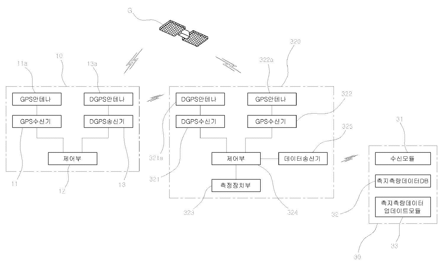
본 발명은 기준국(10)과, 기준국(10)으로부터 보정값 위치신호를 수신하는 측량장치(20)와, 측량장치(20)로부터 측지측량데이터를 수신하는 측지측량데이터통합관리장치(30)를 포함한다.The present invention provides a
상기 기준국(10)은 GPS안테나(11a)를 갖추고서, 인공위성(G)로부터 위치값을 수신받는 GPS수신기(11)와, GPS수신기(11)로부터 전달받은 현재의 위치값과 저장된 절대값을 상호 연산하여 GPS보정값을 출력하는 제어부(12)와, DGPS안테나(13a)를 갖추고서, 제어부(12)로부터 GPS보정값을 전달받아 외부로 무선송출하는 DGPS송신기(13)로 구성된다.The
본 실시예의 경우 상기 기준국(10)의 제어부(12)를 통해 연산된 GPS보정 값(즉 위치 값)은 DGPS송신기(13)로 전달되고, DGPS송신기(13)와 연결된 DGPS안테나(13a)를 통해 이후에 설명된 토탈스테이션(320)의 DGPS안테나(321a)로 무선송출하게 된다. In the present embodiment, the GPS correction value (that is, the position value) calculated by the
상기 측량장치(20)는 거치대(100), 부력기구(200), 토탈스테이션장치(300), 고정장치(400), 위치표시기구(500), 수평감지센서(600), 제어유닛(700) 및, 조명장치(800)를 포함한다.The
상기 거치대(100)는, 패널 형상의 거치대본체(110)와, 거치대본체(110)의 하부에 회동가능하게 설치되는 다수의 다리(120)를 갖춘다.The
상기 거치대본체(110)는 내부에 형성되는 구동장치수용공간(111)과, 상하로 관통형성되어 구동장치수용공간(111)과 연통되는 관통홀(112)을 갖춘다.The cradle
상기 부력기구(200)는 패널 형상의 설치체(210)와, 설치체(210)에 삽입설치되는 부력부재(220)를 갖춘다.The
상기 설치체(210)는 하방으로 개구된 플런저삽입홈(211)과, 하부에 형성되며 하방으로 개구된 다수의 회전볼삽입홈(212)와, 상부에 형성되며 상방으로 돌출되는 고정체(213)를 갖춘다. 이때 설치체(210)는 부력재질로 이루어지는 것이 바람직하다.The
상기 부력부재(220)는 제1부력체(221), 회전축(222), 제2부력체(223), 스토퍼(224), 제1충전체(225) 및, 제2충전체(226)를 갖춘다.The
상기 제1부력체(221)는 중심부에 상하로 관통형성되어 설치체(210)에 삽입되는 설치체삽입홀(221a)과, 내부에 형성되되 설치체삽입홀(221a)의 주변을 둘러서 형성되는 충진체수용공간(221b)과, 측면에 형성되며 외측으로 개구되는 절개홈(221c)을 갖춘다.The
상기 회전축(222)은 제1부력체(221)의 절개홈(221c)에 설치된다. 이때 회전축(222)은 절개홈(221c)의 길이방향을 따라 배치된다.The
상기 제2부력체(223)는 내부에 형성되는 충진체수용공간(223a)을 구비하며 회전축(222)에 회전가능하게 설치된다. The
상기 스토퍼(224)는 일단이 제1부력체(221)에 설치되고 타단이 제2부력체(223)의 상부에 배치되어 제2부력체(223)의 상방이동을 제한한다.One end of the
상기 제1충전체(225)는 부력재질로 제1부력체(221)의 충진체수용공간(221b)에 수용된다. 본 실시예에서 제1충전체(225)는 스티로폼과 같이 물에 뜰 수 있는 것이면 어떤 것이든 무방하다. The
상기 제2충전체(226)는 부력재질로 제2부력체(223)의 충진체수용공간(223a)에 수용된다. 본 실시예에서 제2충전체(226)는 스티로폼과 같이 물에 뜰 수 있는 것이면 어떤 것이든 무방하다. The
상기 회전볼(230)은 설치체(210)의 회전볼삽입홈(212)에 회전가능하게 설치된다. The
상기 토탈스테이션장치(300)는 설치체(210)에 설치되는 고정부(310)와, 고정부(310)의 상부에 구비되는 토탈스테이션(320)를 갖춘다.The
상기 고정부(310)는 하방으로 개구되고, 플런저삽입홈(211)과 동일직경을 이루며, 설치체(210)의 고정체(213)가 삽입고정되는 고정체삽입홈(311)을 갖춘다. The fixing
상기 토탈스테이션(320)는 측정점의 각도와 거리측정, 측정점의 위치좌표를 산출해 표시 및 저장하는 기능 및 유무선 통신기능을 갖추고서, 고정부(310)의 상부에 구비된다.The
상기 토탈스테이션(320)은, 기준국(10)으로부터 GPS보정 값과 위성(G)로부터 받은 GPS 값을 연산하여, 자신의 정밀위치를 확인하고, 상기 정밀위치를 기준으로 측정점의 좌표를 연산처리하기 위해 측정점의 각도와 거리를 정밀 측위하여 유,무선 송출한다. The
그리고 상기 토탈스테이션(320)은, DGPS안테나(321a)를 갖추고서, 기준국(10)의 DGPS송신기(13)로부터 GPS보정 값을 수신받는 DGPS수신기(321)와, GPS안테나(222a)를 갖추고서, 위성(G)으로부터 현재 위치값을 수신받는 GPS수신기(322)와, 일측에 렌즈부를 갖추고서, 측정점의 각도와 거리를 정밀측정할 수 있도록 된 측정장치부(323)와, DGPS수신기(321)로부터 받은 GPS보정 값을 이용하여 GPS안테나(322a)의 정밀위치 연산을 통해 토탈스테이션(320)의 정밀위치를 확인하고, 측정장치부(323)로부터 측정된 측정점의 각도와 거리를 입력받아 상기 정밀위치를 기준으로 상기 측정점의 위치좌표를 연산처리하는 제어부(324)와, 측지측량된 측지측량데이터를 외부로 무선출력하는 데이터송신기(325)를 갖춘다.The
한편 상기 토탈스테이션(320)은 측지 측량에 사용되는 통상의 것으로 이에 대한 자세한 설명은 생략하기로 한다.Meanwhile, the
상기 고정장치(400)는 거치대본체(110)의 구동장치수용공간(111)에 수용되는 솔레노이드(410)와, 솔레노이드(410)의 구동에 따라 설치체(210)의 플런저삽입홈(211)에 삽탈되는 플런저(420)를 갖춘다. 이때 고정장치(400)는 부력기구(200)의 설치체(210)를 고정 또는 해제할 수 있는 것이면, 다양하게 변형실시될 수 있다.The fixing
상기 위치표시기구(500)는 깨짐기구(510), 표시부재(520), 고정와이어(530)를 갖추고서, 설치체(210)의 플런저삽입홈(211)에 수용되되, 고정장치(400)의 플런저(420)의 상부에 배치된다.The
상기 깨짐기구(510)는 깨짐기구본체(511)와, 고정축(512)과, 깨짐부재(513)과, 무게추(514)를 갖춘다. The
상기 깨짐기구본체(511)는 내부에 형성되는 표시체수용공간(511a)과, 측면에 측방향으로 관통형성되며 표시체수용공간(511a)과 연통되는 깨짐홀(511b)을 갖춘다.The
상기 고정축(512)은 깨짐홀(511b)의 양측면에 설치되고, 내측으로 돌출되며, 일정 기준 이상의 압력이 가해지면 부러진다. 이때 고정축(512)은 주위의 다른 부재에 비해 약한 재질로 이루어진다.The fixed
상기 깨짐부재(513)는 양단부가 고정축(512)에 삽탈가능하게 삽입되어 깨짐홀(511b)을 폐쇄한다. Both ends of the cracking
상기 무게추(514)는 깨짐부재(513)에 대향되게 깨짐기구본체(511)의 일측에 설치되어 깨짐기구본체(511)가 기울도록 일정 하중을 갖는다.The
상기 표시부재(520)는 표시체수용공간(511a)에 수용되며 내부에 공기보다 밀도가 작은 기체가 수용된 구형의 표시체(521)와, 일단이 표시체(521)에 연결되고 타단이 깨짐부재(513)의 일측에 연결되는 제1표시와이어(522)와, 일단이 깨짐부재(513)의 일측에 연결되고 타단이 고정장치(400)의 플런저(420)에 연결되는 제2표시와이어(523)를 갖춘다. The
상기 고정와이어(530)는 일단이 깨짐기구(510)의 무게추(514)에 고정되고 타단이 설치체(210)의 플런저삽입홈(211)에 연결된다. One end of the
한편 상기 제1표시와이어(522)·제2표시와이어(523)·고정와이어(530)는 부력기구(200)와 토탈스테이션장치(300)가 분리되고, 표시체(521)가 부양될 수 있도록 충분한 길이를 갖는 것이 바람직하다.Meanwhile, the
상기 수평감지센서(600)는 거치대본체(110)에 설치되며, 거치대본체(110)의 수평 정도를 감지한다. 본 실시예에서 수평감지센서(600)는 일반적인 주지관용기술로서 이에 대한 자세한 설명은 생략하기로 한다. 또한 본 실시예에서는 통상적인 기울기 센서를 통해 거치대본체(110)의 수평 정도를 감지할 수 있다.The
상기 제어유닛(700)은 거치대본체(110)에 설치되어 수평감지센서(600) 및 고정장치(400)를 작동제어한다. 본 실시예에서 제어유닛(700)은 거치대본체(110)의 수평 정도에 따라 고정장치(400)를 작동제어한다.The
상기 조명장치(800)는 측량장치(10)에 설치되며 제어유닛(700)에 의해 작동제어되어 조도를 감지하는 조도센서(810)와, 거치대본체(110) 및 부력부재(220)에 설치되며 제어유닛(700)에 의해 작동제어되어 조도센서(810)로부터의 조도신호에 따라 점등되는 조명등(820)을 갖춘다. 본 실시예에서 조도센서(810) 및 조명등(820)은 일반적으로 널리 알려진 주지관용기술로서, 이에 대한 자세한 구조적 설명은 생략하기로 한다. 또한 본 실시예에서 조도센서(810)는 조도를 감지할 수 있는 것이면 측량장치(10)의 어느 곳에 설치되도 무방하다.The
상기 측지측량데이터통합관리장치(30)는 측량장치(20)의 토탈스테이션(320)으로부터 측지측량데이터를 수신하는 수신모듈(31)과, 기존 측지측량데이터 및 수신모듈(31)로부터 수신된 측지측량데이터를 저장하는 측지측량데이터DB(32)와, 기존의 측지측량데이터와 새로운 측지측량데이터를 비교하여 측지측량데이터DB(32)의 측지측량데이터를 업데이트하는 측지측량데이터업데이트모듈(33)를 갖추고서, 다양한 지역으로부터의 측지측량데이터를 통합관리한다.
The geodetic survey data integrated
도 10 내지도 18은 본 발명의 작용을 설명하기 위한 것으로, 도 10 내지 도 18를 참조하여 본 발명의 작용을 설명하면 다음과 같다. 10 to 18 are for explaining the operation of the present invention, the operation of the present invention with reference to FIGS. 10 to 18 as follows.
우선 작업자는 물가에서 기준 측량 또는 수준 측량을 하기 위해서 도 10과 같이 본 발명의 부력기구(200) 및 토탈스테이션(320)가 물 밖으로 노출되도록 토탈스테이션을 수중에 설치한다.First, the operator installs the total station in water so that the
이때 상기 부력기구(200)의 제2부력체(223)는 하방으로 접혀있어, 작업자가 측지측량작업을 수행할 시, 공간활용을 충분히 할 수 있어, 작업을 매우 편리하게 수행할 수 있다.At this time, the
이후 상기 작업자는 토탈스테이션장치(300)를 측지측량이 필요한 주변을 측량한다.After that, the operator surveys the
이때 측지측량된 측지측량데이터는 데이터송신기(325)을 통해 외부로 무선출력되고, 측지측량데이터통합관리장치(30)의 수신모듈(31)은 이를 수신하며, 수신된 측지측량데이터는 측지측량데이터DB(32)에 저장된다.At this time, the geodetic geodetic surveying data is wirelessly output to the outside through the
그러면 상기 측지측량데이터업데이트모듈(33)은 기존의 측지측량데이터와 새로운 측지측량데이터를 비교하여 측지측량데이터DB(32)의 측지측지측량데이터를 업데이트한다. 측지측량데이터통합관리장치(30)는 이러한 업데이트 과정을 통해 최신의 측지측량데이터를 보유할 수 있다.The geodetic survey
이때 상기 측지측량작업이 마무리되어 주변을 정리할 시, 주변이 어두우면 조도감지센서(810)는 조도신호를 출력하고, 이를 수신한 제어유닛(700)은 도 11과 같이 조명등(820)을 점등한다.At this time, when the geodetic surveying work is finished to clean up the surroundings, when the surroundings are dark, the
따라서 상기 작업자는 측지측량작업을 마무리하면서 주변을 정리할 시, 안전하게할 수 있다.Therefore, the worker can be safe when cleaning the surroundings while finishing the geodetic survey work.
한편 상기 작업자가 주변을 측지측량 하던 중 예상치 못한 외력에 의해 도 12와 같이 거치대(100)가 넘어질 경우, 토탈스테이션장치(300)가 물에 빠질 수 있어, 토탈스테이션장치(300)가 고장날 수 있다.On the other hand, if the
하지만 본 발명의 경우, 도 12와 같이 거치대(100)가 넘어질 경우, 거치대(100)와 토탈스테이션장치(300)가 분리되어, 토탈스테이션장치(300)가 물에 빠지지 않는다.However, in the present invention, when the
즉 상기 거치대(100)가 넘어질 경우, 수평감지센서(600)는 거치대(100)의 기울기를 감지하고, 기울기가 설정 범위를 벗어나면, 제어유닛(700)에 의해 고정장치(400)가 구동되어, 도 13과 같이 부력기구(200)와 토탈스테이션장치(300)의 결합이 해제된다.That is, when the
그러면 상기 부력기구(200)는 도 14 및 도 15와 같이 수면에 미끄러지듯 안착되고, 거치대(100)는 수중에 가라앉는다.Then, the
이때 상기 부력기구(200) 및 토탈스테이션장치(300)는 위치표시기구(500)를 통해 연결되어 있어, 작업자는 거치대(100)· 부력기구(200)·토탈스테이션장치(300)를 쉽게 찾을 수 있다.At this time, the
하지만 상기 거치대(100)· 부력기구(200)·토탈스테이션장치(300)가 넘어져 있는 상태에서 거치대(100)· 부력기구(200)·토탈스테이션장치(300) 중 어느 하나에 강한 물살이 부딪힐 경우, 거치대(100)· 부력기구(200)·토탈스테이션장치(300)는 함께 물살에 휩쓸려 사라진다.However, when the
그러나 본 발명의 경우, 거치대(100)· 부력기구(200)·토탈스테이션장치(300)에 기준 이상의 외력이 가해지면, 표시부재(520)의 제2표시와이어(523)가 위치표시기구(500)의 깨짐부재(513)을 당기고, 이로 인해 위치표시기구(500)의 고정축(512)이 도 16과 같이 깨져, 깨짐기구본체(511)의 깨짐홀(511b)가 개방된다.However, in the present invention, when the external force is applied to the
이때 상기 깨짐기구(510)는 무게추(514)에 의해 도 17과 같이 깨짐홀(511b)이 상방을 향하도록 위치한다. 따라서 표시체(521)는 부력에 의해 상방으로 이동할 시 좀 더 용이하게 깨짐기구본체(511)로부터 이탈되고, 도 18과 같이 표시체(521)가 수면 위로 부상하여, 거치대(100) 및 부력기구(200)가 분리된다.At this time, the cracking
그러면 상기 거치대(100) 및 부력기구(200)·토탈스테이션장치(300) 중 외력을 받은 것만 물살에 이동하게 되어, 거치대(100)· 부력기구(200)·토탈스테이션장치(300) 모두가 물살에 사라지지 않는다.Then, the
특히 본 발명에서는 표시체(521)가 부상하여, 제2표시와이어(523) 및 표시체(521)를 통해 거치대(100)의 위치를 쉽게 확인할 수 있어, 거치대(100)를 분실할 염려가 없다.In particular, in the present invention, the
또한 본 발명에서는 부력기구(200)에 의해 토탈스테이션장치(300)가 부양되어 있어, 측걱측각장치(300)를 분실하지 않고 쉽게 찾을 수 있다.
In addition, in the present invention, the
상술한 바와 같이 본 발명은 측지측량이 필요한 다양한 지역에서 측지측량한 측지측량데이터를 측지측량데이터통합관리장치(30)에서 통합관리할 수 있어, 측지측량데이터를 효율적으로 관리할 수 있다.As described above, according to the present invention, the geodetic surveying data obtained by geodetic surveying in various regions where geodetic surveying is required can be integrated and managed by the geodetic survey data integrated
또한 본 발명은 야간에 측지측량작업을 마무리할 시, 주변 장비를 안전하게 정리할 수 있다.In addition, the present invention can clean up the surrounding equipment safely at the end of the geodetic surveying work at night.
또한 본 발명은 물가에서 토탈스테이션의 손상없이 측지측량을 안정적으로 할 수 있다.In addition, the present invention can be stabilized geodetic survey without damage to the total station at the waterside.
또한 본 발명은 물가에서 측지측량 작업 중, 토탈스테이션이 넘어질 시, 토탈스테이션이 수중에 잠기지 않게 함으로써, 토탈스테이션의 손상을 방지한다.In addition, the present invention prevents damage to the total station by preventing the total station from being submerged in water when the total station falls down during geodetic surveying operation at the waterside.
또한 본 발명은 물가에서 측지측량 작업 중, 토탈스테이션이 넘어질 시, 토탈스테이션을 찾기가 용이하다.In addition, the present invention is easy to find the total station when the total station falls during geodetic surveying work in the water.
10; 기준국 20; 측량장치
100; 거치대 110; 거치대본체
120; 다리 200; 부력기구
210; 설치체 220; 부력부재
300; 토탈스테이션장치 310; 고정부
320; 토탈스테이션 400; 고정장치
410; 솔레노이드 420; 플런저
500; 위치표시기구 510; 깨짐기구
520; 표시부재 530; 고정와이어
600; 수평감지센서 700; 제어유닛
800; 조명장치 30; 측지측량데이터통합관리장치
31; 수신모듈 32; 측지측량데이터DB
33; 측지측량데이터업데이트모듈10;
100;
120;
210;
300;
320;
410;
500;
520;
600;
800;
31; Receiving
33; Geodetic Survey Data Update Module
Claims (1)
내부에 형성되는 구동장치수용공간(111)과, 상하로 관통형성되어 구동장치수용공간(111)과 연통되는 관통홀(112)을 구비한 거치대본체(110), 거치대본체(110)에 회동가능하게 설치되는 다수의 다리(120)를 갖춘 거치대(100)와:
하방으로 개구된 플런저삽입홈(211), 하부에 형성되며 하방으로 개구된 다수의 회전볼삽입홈(212), 상부에 형성되며 상방으로 돌출되는 고정체(213)를 구비한 설치체(210)와; 중심부에 상하로 관통형성되어 설치체(210)에 삽입되는 설치체삽입홀(221a)과, 내부에 형성되는 충진체수용공간(221b)와, 측면에 형성되며 외측으로 개구되는 절개홈(221c)을 구비한 제1부력체(221), 제1부력체(221)의 절개홈(221c)에 설치되는 회전축(222), 내부에 형성되는 충진체수용공간(223a)을 구비하며 회전축(222)에 회전가능하게 설치되는 제2부력체(223), 일단이 제1부력체(221)에 설치되고 타단이 제2부력체(223)의 상부에 배치되어 제2부력체(223)의 상방이동을 제한하는 스토퍼(224)와; 제1부력체(221)의 충진체수용공간(221b)에 수용되는 부력재질의 제1충진체(225)와; 제2부력체(223)의 충진체수용공간(223a)에 수용되는 부력재질의 제2충진체(226)를 구비한 부력부재(220)와; 설치체(210)의 회전볼삽입홈(212)에 회전가능하게 설치되는 다수의 회전볼(230)을 갖춘 부력기구(200)와:
하방으로 개구되고 플런저삽입홈(211)과 동일직경을 이루며 설치체(210)의 고정체(213)가 삽입고정되는 고정체삽입홈(311)을 구비한 고정부(310)와; 측정점의 각도와 거리측정, 측정점의 위치좌표를 산출해 표시 및 저장하는 기능 및 유무선 통신기능을 갖추고서, 고정부(310)에 설치되는 토탈스테이션(320)를 갖춘 토탈스테이션장치(300)와:
거치대본체(110)의 구동장치수용공간(111)에 수용되는 솔레노이드(410)와; 솔레노이드(410)의 구동에 따라 설치체(210)의 플런저삽입홈(211)에 삽탈되는 플런저(420)를 갖춘 고정장치(400)와:
내부에 형성되는 표시체수용공간(511a)과, 측면에 측방향으로 관통형성되며 표시체수용공간(511a)과 연통되는 깨짐홀(511b)을 구비한 깨짐기구본체(511), 깨짐홀(511b)에 설치되며 일정 기준 이상의 압력이 가해지면 부러지는 고정축(512), 단부가 고정축(512)에 삽탈가능하게 삽입되어 깨짐홀(511b)을 폐쇄하는 깨짐부재(513), 깨짐부재(513)에 대향되게 깨짐기구본체(511)의 일측에 설치되어 깨짐기구본체(511)가 기울도록 일정 하중을 갖는 무게추(514)를 갖춘 깨짐기구(510)와; 표시체수용공간(511a)에 수용되며 내부에 공기보다 밀도가 작은 기체가 수용된 구형의 표시체(521), 일단이 표시체(521)에 연결되고 타단이 깨짐부재(513)의 일측에 연결되는 제1표시와이어(522), 일단이 깨짐부재(513)의 일측에 연결되고 타단이 고정장치(400)의 플런저(420)에 연결되는 제2표시와이어(523)를 구비한 표시부재(520)와; 일단이 깨짐기구(510)의 무게추(514)에 고정되고 타단이 설치체(210)의 플런저삽입홈(211)에 연결되는 고정와이어(530); 를 갖추고서, 설치체(210)의 플런저삽입홈(211)에 수용되되, 고정장치(400)의 플런저(420)의 상부에 배치되는 위치표시기구(500)와:
거치대본체(110)에 설치되며, 거치대본체(110)의 수평 정도를 감지하는 수평감지센서(600)와:
거치대본체(110)에 설치되며, 거치대본체(110)의 수평 정도에 따라 고정장치(400)를 작동제어하는 제어유닛(700):
제어유닛(700)에 의해 작동제어되며, 조도를 감지하는 조도센서(810); 거치대본체(110) 및 부력부재(220)에 설치되며, 제어유닛(700)에 의해 작동제어되어, 조도센서(810)로부터의 조도신호에 따라 점등되는 조명등(820)을 구비한 조명장치(800):
를 갖춘 측량장치(20),
측량장치(20)의 토탈스테이션(320)으로부터 측지측량데이터를 수신하는 수신모듈(31); 기존 측지측량데이터 및 수신모듈(31)로부터 수신된 측지측량데이터를 저장하는 측지측량데이터DB(32); 기존의 측지측량데이터와 새로운 측지측량데이터를 비교하여 측지측량데이터DB(32)의 측지측량데이터를 업데이트하는 측지측량데이터업데이트모듈(33)를 갖춘 측지측량데이터통합관리장치(30),
를 포함하는 것을 특징으로 하는 토탈스테이션의 데이터를 처리하는 측지측량 데이터 수집전용 통합관리시스템.A reference station 10 which receives the current position value from the satellite G and wirelessly transmits the GPS correction value by mutually computing the current position value and the stored absolute value,
Can be rotated to the cradle main body 110 and the cradle main body 110 having a drive device accommodation space 111 formed therein, and a through hole 112 formed to penetrate up and down to communicate with the drive device accommodation space 111. And cradle 100 with a plurality of legs 120 to be installed:
An installation body 210 having a plunger insertion groove 211 opened downward, a plurality of rotary ball insertion grooves 212 formed at a lower side thereof, and a fixing body 213 formed at an upper portion and protruding upwardly. Wow; The installation body insertion hole 221a which is formed to penetrate up and down in the center and is inserted into the installation body 210, the filling body accommodating space 221b formed therein, and the incision groove 221c which is formed on the side and is opened outward. The first buoyancy body 221, the rotating shaft 222 is installed in the cutting groove (221c) of the first buoyancy body 221, the filling body receiving space 223a formed therein and the rotating shaft 222 The second buoyancy body 223 rotatably installed at one end, one end is installed in the first buoyancy body 221 and the other end is disposed above the second buoyancy body 223 to move upward of the second buoyancy body 223 A stopper 224 for restricting; A first filler 225 of buoyancy material accommodated in the filler receiving space 221b of the first buoyancy body 221; A buoyancy member 220 having a second filler 226 of buoyancy material accommodated in the filler receiving space 223a of the second buoyancy body 223; A buoyancy mechanism 200 having a plurality of rotary balls 230 rotatably installed in the rotary ball insertion groove 212 of the installation body 210 and:
A fixing part 310 opening downward and having a fixing body inserting groove 311 having the same diameter as that of the plunger inserting groove 211 and into which the fixing body 213 of the mounting body 210 is inserted and fixed; The total station apparatus 300 having a total station 320 installed in the fixing unit 310 and having a function of measuring and displaying the angle and distance of the measuring point, calculating and displaying the position coordinates of the measuring point, and wired / wireless communication functions:
A solenoid 410 accommodated in the drive unit accommodation space 111 of the holder main body 110; A fixing device 400 having a plunger 420 inserted into and out of the plunger insertion groove 211 of the mounting body 210 according to the driving of the solenoid 410 and:
A cracking mechanism body 511 and a cracking hole 511b having a display body accommodating space 511a formed therein and a crack hole 511b formed laterally through the side surface and communicating with the display body accommodating space 511a. And a fixed shaft 512 that is broken when a pressure exceeding a predetermined standard is applied, and an end portion of the fixed shaft 512 is inserted into the fixed shaft 512 to close the crack hole 511b, and the crack member 513. A cracking mechanism 510 installed at one side of the cracking mechanism body 511 to have a weight 514 having a predetermined load so that the cracking mechanism body 511 is inclined; The spherical display body 521 is accommodated in the display body receiving space (511a) and the gas is less dense than air therein, one end is connected to the display body 521, the other end is connected to one side of the broken member 513 Display member 520 having a first display wire 522, one end is connected to one side of the broken member 513 and the other end is connected to the plunger 420 of the fixing device 400. Wow; A fixing wire 530 whose one end is fixed to the weight 514 of the breaking mechanism 510 and the other end is connected to the plunger insertion groove 211 of the mounting body 210; With a position indicator mechanism 500 is accommodated in the plunger insertion groove 211 of the mounting body 210, the upper portion of the plunger 420 of the fixing device 400 and:
Installed on the main body 110, the horizontal detection sensor 600 for detecting the horizontal degree of the main body 110 and:
Control unit 700 is installed in the main body 110, the operation unit for controlling the fixing device 400 in accordance with the horizontal degree of the main body 110:
An illumination control sensor 810 which is operated and controlled by the control unit 700 and detects illuminance; The lighting device 800 is installed on the main body 110 and the buoyancy member 220, the operation apparatus is controlled by the control unit 700, the lighting device 800 having a lamp 820 that is turned on in accordance with the illumination signal from the illumination sensor 810 ):
Surveying device with a 20,
A receiving module 31 for receiving geodetic survey data from the total station 320 of the surveying apparatus 20; Geodetic survey data DB 32 for storing the existing geodetic data and geodetic data received from the receiving module 31; Geodetic survey data integrated management device 30 having a geodetic survey data update module 33 for updating the geodetic survey data of the geodetic survey data DB 32 by comparing existing geodetic data with new geodetic survey data;
Integrated management system dedicated to geodetic survey data collection processing data of the total station comprising a.
Priority Applications (1)
| Application Number | Priority Date | Filing Date | Title |
|---|---|---|---|
| KR1020120057571A KR101221663B1 (en) | 2012-05-30 | 2012-05-30 | Geodetic survey data integration management system |
Applications Claiming Priority (1)
| Application Number | Priority Date | Filing Date | Title |
|---|---|---|---|
| KR1020120057571A KR101221663B1 (en) | 2012-05-30 | 2012-05-30 | Geodetic survey data integration management system |
Publications (1)
| Publication Number | Publication Date |
|---|---|
| KR101221663B1 true KR101221663B1 (en) | 2013-01-14 |
Family
ID=47841740
Family Applications (1)
| Application Number | Title | Priority Date | Filing Date |
|---|---|---|---|
| KR1020120057571A Expired - Fee Related KR101221663B1 (en) | 2012-05-30 | 2012-05-30 | Geodetic survey data integration management system |
Country Status (1)
| Country | Link |
|---|---|
| KR (1) | KR101221663B1 (en) |
Cited By (2)
| Publication number | Priority date | Publication date | Assignee | Title |
|---|---|---|---|---|
| KR101542074B1 (en) | 2011-01-10 | 2015-08-12 | 라이카 게오시스템스 아게 | Geodesic measuring device comprising a thermographic camera |
| KR101915290B1 (en) | 2018-05-30 | 2018-11-05 | 주식회사 미래지중정보 | Geodetic surveying equipment for improved accuracy by the datum point |
Citations (4)
| Publication number | Priority date | Publication date | Assignee | Title |
|---|---|---|---|---|
| KR100936287B1 (en) | 2009-08-13 | 2010-01-13 | 대주항업 주식회사 | Drawing system for video image updating of gps fiducial point mixing method |
| KR101062420B1 (en) | 2011-05-11 | 2011-09-06 | (주)선영종합엔지니어링 | Ground surveying system for comparative analysis of digital map information by reference point for GPS coordinates |
| KR20120021668A (en) * | 2010-08-12 | 2012-03-09 | 새한항업(주) | Image imformation's monitoring system |
| KR101115603B1 (en) | 2011-11-25 | 2012-03-13 | 주식회사 공간정보 | Measurement data collection system |
-
2012
- 2012-05-30 KR KR1020120057571A patent/KR101221663B1/en not_active Expired - Fee Related
Patent Citations (4)
| Publication number | Priority date | Publication date | Assignee | Title |
|---|---|---|---|---|
| KR100936287B1 (en) | 2009-08-13 | 2010-01-13 | 대주항업 주식회사 | Drawing system for video image updating of gps fiducial point mixing method |
| KR20120021668A (en) * | 2010-08-12 | 2012-03-09 | 새한항업(주) | Image imformation's monitoring system |
| KR101062420B1 (en) | 2011-05-11 | 2011-09-06 | (주)선영종합엔지니어링 | Ground surveying system for comparative analysis of digital map information by reference point for GPS coordinates |
| KR101115603B1 (en) | 2011-11-25 | 2012-03-13 | 주식회사 공간정보 | Measurement data collection system |
Cited By (2)
| Publication number | Priority date | Publication date | Assignee | Title |
|---|---|---|---|---|
| KR101542074B1 (en) | 2011-01-10 | 2015-08-12 | 라이카 게오시스템스 아게 | Geodesic measuring device comprising a thermographic camera |
| KR101915290B1 (en) | 2018-05-30 | 2018-11-05 | 주식회사 미래지중정보 | Geodetic surveying equipment for improved accuracy by the datum point |
Similar Documents
| Publication | Publication Date | Title |
|---|---|---|
| US9255798B2 (en) | Survey device | |
| US9441963B2 (en) | Multifunction laser leveling tool | |
| KR101116190B1 (en) | Geodetic survey data management system | |
| KR101217602B1 (en) | Geodetic survey system | |
| KR101531025B1 (en) | Apparatus for protecting tripod in geodetic survey | |
| KR101233719B1 (en) | Apparatus for measuring of national level control point usingand visual information in geodetic surveying | |
| WO2017066836A1 (en) | A survey staff | |
| KR101779072B1 (en) | Geodetic surveying device for road and underground facility using gps and drone and geodetic surveying method using that | |
| KR101318269B1 (en) | Geographical information survey ground surface data measuring system for surveying and updating by confirmation standard point and leveling point | |
| KR101221663B1 (en) | Geodetic survey data integration management system | |
| KR101318257B1 (en) | Total geographic point and level point information gathering system for applying results of the geographical observation data | |
| KR101209247B1 (en) | Total station for collecting geodetic survey data | |
| ES2718338T3 (en) | Apparatus for aligning drilling machines | |
| KR102336835B1 (en) | Geodetic surveying system for improving precision of surveying using national control point | |
| KR101116193B1 (en) | Geodetic survey data management system | |
| KR101494855B1 (en) | Bench mark surveying system | |
| KR100837261B1 (en) | GPS-based reference point correction system for checking terrain changes | |
| KR101220486B1 (en) | Geodetic survey data precision update system | |
| JP2008014893A (en) | Inclinometer and measuring method using the same | |
| JP2002031529A (en) | Automated position measuring system and method therefor | |
| KR101213605B1 (en) | Geodetic survey data management system | |
| KR101008324B1 (en) | Geodetic and survey confirmation systems of features based on GPS coordinates | |
| KR20170007874A (en) | Sinkhole monitoring system with gps | |
| KR101239932B1 (en) | Image map making system for topography be based on the reference point image | |
| CN210321605U (en) | Multifunctional measuring instrument |
Legal Events
| Date | Code | Title | Description |
|---|---|---|---|
| A201 | Request for examination | ||
| PA0109 | Patent application |
St.27 status event code: A-0-1-A10-A12-nap-PA0109 |
|
| PA0201 | Request for examination |
St.27 status event code: A-1-2-D10-D11-exm-PA0201 |
|
| A302 | Request for accelerated examination | ||
| PA0302 | Request for accelerated examination |
St.27 status event code: A-1-2-D10-D17-exm-PA0302 St.27 status event code: A-1-2-D10-D16-exm-PA0302 |
|
| D13-X000 | Search requested |
St.27 status event code: A-1-2-D10-D13-srh-X000 |
|
| D14-X000 | Search report completed |
St.27 status event code: A-1-2-D10-D14-srh-X000 |
|
| E902 | Notification of reason for refusal | ||
| PE0902 | Notice of grounds for rejection |
St.27 status event code: A-1-2-D10-D21-exm-PE0902 |
|
| P11-X000 | Amendment of application requested |
St.27 status event code: A-2-2-P10-P11-nap-X000 |
|
| P13-X000 | Application amended |
St.27 status event code: A-2-2-P10-P13-nap-X000 |
|
| E701 | Decision to grant or registration of patent right | ||
| PE0701 | Decision of registration |
St.27 status event code: A-1-2-D10-D22-exm-PE0701 |
|
| GRNT | Written decision to grant | ||
| PR0701 | Registration of establishment |
St.27 status event code: A-2-4-F10-F11-exm-PR0701 |
|
| PR1002 | Payment of registration fee |
St.27 status event code: A-2-2-U10-U11-oth-PR1002 Fee payment year number: 1 |
|
| PG1601 | Publication of registration |
St.27 status event code: A-4-4-Q10-Q13-nap-PG1601 |
|
| LAPS | Lapse due to unpaid annual fee | ||
| PC1903 | Unpaid annual fee |
St.27 status event code: A-4-4-U10-U13-oth-PC1903 Not in force date: 20160108 Payment event data comment text: Termination Category : DEFAULT_OF_REGISTRATION_FEE |
|
| P22-X000 | Classification modified |
St.27 status event code: A-4-4-P10-P22-nap-X000 |
|
| PC1903 | Unpaid annual fee |
St.27 status event code: N-4-6-H10-H13-oth-PC1903 Ip right cessation event data comment text: Termination Category : DEFAULT_OF_REGISTRATION_FEE Not in force date: 20160108 |
|
| R18-X000 | Changes to party contact information recorded |
St.27 status event code: A-5-5-R10-R18-oth-X000 |
|
| P22-X000 | Classification modified |
St.27 status event code: A-4-4-P10-P22-nap-X000 |
|
| PN2301 | Change of applicant |
St.27 status event code: A-5-5-R10-R13-asn-PN2301 St.27 status event code: A-5-5-R10-R11-asn-PN2301 |
|
| R18-X000 | Changes to party contact information recorded |
St.27 status event code: A-5-5-R10-R18-oth-X000 |
|
| PN2301 | Change of applicant |
St.27 status event code: A-5-5-R10-R13-asn-PN2301 St.27 status event code: A-5-5-R10-R11-asn-PN2301 |
|
| R11 | Change to the name of applicant or owner or transfer of ownership requested |
Free format text: ST27 STATUS EVENT CODE: A-5-5-R10-R11-ASN-PN2301 (AS PROVIDED BY THE NATIONAL OFFICE) |
|
| R13 | Change to the name of applicant or owner recorded |
Free format text: ST27 STATUS EVENT CODE: A-5-5-R10-R13-ASN-PN2301 (AS PROVIDED BY THE NATIONAL OFFICE) |