KR100637791B1 - Functional element, method for fixing it in a sheet metal part, assembling element and swaging assembly - Google Patents
Functional element, method for fixing it in a sheet metal part, assembling element and swaging assembly Download PDFInfo
- Publication number
- KR100637791B1 KR100637791B1 KR1020027000344A KR20027000344A KR100637791B1 KR 100637791 B1 KR100637791 B1 KR 100637791B1 KR 1020027000344 A KR1020027000344 A KR 1020027000344A KR 20027000344 A KR20027000344 A KR 20027000344A KR 100637791 B1 KR100637791 B1 KR 100637791B1
- Authority
- KR
- South Korea
- Prior art keywords
- sheet metal
- functional member
- plunger
- annular
- portions
- Prior art date
Links
- 229910052751 metal Inorganic materials 0.000 title claims abstract description 144
- 239000002184 metal Substances 0.000 title claims abstract description 144
- 238000000034 method Methods 0.000 title claims abstract description 47
- 239000000463 material Substances 0.000 claims description 28
- 239000002131 composite material Substances 0.000 claims description 24
- 230000008569 process Effects 0.000 claims description 12
- 238000005520 cutting process Methods 0.000 claims description 6
- 238000003825 pressing Methods 0.000 claims description 6
- 238000003780 insertion Methods 0.000 claims description 5
- 230000037431 insertion Effects 0.000 claims description 5
- 238000000465 moulding Methods 0.000 claims description 5
- 241000237858 Gastropoda Species 0.000 claims description 4
- 238000000748 compression moulding Methods 0.000 claims description 2
- 238000004080 punching Methods 0.000 claims description 2
- 238000005096 rolling process Methods 0.000 claims description 2
- 238000007493 shaping process Methods 0.000 claims 2
- 239000011159 matrix material Substances 0.000 abstract description 3
- 239000010410 layer Substances 0.000 description 25
- 210000003128 head Anatomy 0.000 description 24
- 239000006260 foam Substances 0.000 description 22
- 210000001331 nose Anatomy 0.000 description 19
- 238000004519 manufacturing process Methods 0.000 description 11
- 239000006262 metallic foam Substances 0.000 description 11
- 239000011162 core material Substances 0.000 description 8
- 239000011796 hollow space material Substances 0.000 description 8
- 238000007906 compression Methods 0.000 description 6
- 239000004033 plastic Substances 0.000 description 6
- 229910000831 Steel Inorganic materials 0.000 description 5
- 229910045601 alloy Inorganic materials 0.000 description 5
- 239000000956 alloy Substances 0.000 description 5
- 238000005266 casting Methods 0.000 description 5
- 238000000576 coating method Methods 0.000 description 5
- 230000000295 complement effect Effects 0.000 description 5
- 230000006835 compression Effects 0.000 description 5
- 238000013461 design Methods 0.000 description 5
- 239000010959 steel Substances 0.000 description 5
- FYYHWMGAXLPEAU-UHFFFAOYSA-N Magnesium Chemical compound [Mg] FYYHWMGAXLPEAU-UHFFFAOYSA-N 0.000 description 4
- 230000008901 benefit Effects 0.000 description 4
- 229910052749 magnesium Inorganic materials 0.000 description 4
- 239000011777 magnesium Substances 0.000 description 4
- 230000007704 transition Effects 0.000 description 4
- 229910052782 aluminium Inorganic materials 0.000 description 3
- XAGFODPZIPBFFR-UHFFFAOYSA-N aluminium Chemical compound [Al] XAGFODPZIPBFFR-UHFFFAOYSA-N 0.000 description 3
- 239000000945 filler Substances 0.000 description 3
- 238000012966 insertion method Methods 0.000 description 3
- 229910000861 Mg alloy Inorganic materials 0.000 description 2
- 230000009471 action Effects 0.000 description 2
- 239000011111 cardboard Substances 0.000 description 2
- 239000001913 cellulose Substances 0.000 description 2
- 229920002678 cellulose Polymers 0.000 description 2
- 238000005553 drilling Methods 0.000 description 2
- 239000007769 metal material Substances 0.000 description 2
- 239000000203 mixture Substances 0.000 description 2
- 238000012545 processing Methods 0.000 description 2
- 229910000838 Al alloy Inorganic materials 0.000 description 1
- OKTJSMMVPCPJKN-UHFFFAOYSA-N Carbon Chemical compound [C] OKTJSMMVPCPJKN-UHFFFAOYSA-N 0.000 description 1
- 229910000975 Carbon steel Inorganic materials 0.000 description 1
- 239000004820 Pressure-sensitive adhesive Substances 0.000 description 1
- 239000000853 adhesive Substances 0.000 description 1
- 230000001070 adhesive effect Effects 0.000 description 1
- 238000005452 bending Methods 0.000 description 1
- 230000015572 biosynthetic process Effects 0.000 description 1
- 238000005219 brazing Methods 0.000 description 1
- 229910052799 carbon Inorganic materials 0.000 description 1
- 239000010962 carbon steel Substances 0.000 description 1
- 239000000919 ceramic Substances 0.000 description 1
- 230000008859 change Effects 0.000 description 1
- 239000011248 coating agent Substances 0.000 description 1
- 239000011247 coating layer Substances 0.000 description 1
- 230000007797 corrosion Effects 0.000 description 1
- 238000005260 corrosion Methods 0.000 description 1
- 238000013016 damping Methods 0.000 description 1
- 230000001419 dependent effect Effects 0.000 description 1
- 238000010586 diagram Methods 0.000 description 1
- 238000009826 distribution Methods 0.000 description 1
- 230000000694 effects Effects 0.000 description 1
- 238000009713 electroplating Methods 0.000 description 1
- 238000001125 extrusion Methods 0.000 description 1
- 210000000887 face Anatomy 0.000 description 1
- 238000005187 foaming Methods 0.000 description 1
- 239000011888 foil Substances 0.000 description 1
- 239000004922 lacquer Substances 0.000 description 1
- 238000002844 melting Methods 0.000 description 1
- 230000008018 melting Effects 0.000 description 1
- 239000012528 membrane Substances 0.000 description 1
- 239000000123 paper Substances 0.000 description 1
- 239000002984 plastic foam Substances 0.000 description 1
- 239000000843 powder Substances 0.000 description 1
- 239000002994 raw material Substances 0.000 description 1
- 229920005989 resin Polymers 0.000 description 1
- 239000011347 resin Substances 0.000 description 1
- 230000004044 response Effects 0.000 description 1
- 238000000926 separation method Methods 0.000 description 1
- 238000005476 soldering Methods 0.000 description 1
- 239000000126 substance Substances 0.000 description 1
- 229920001187 thermosetting polymer Polymers 0.000 description 1
- 238000012546 transfer Methods 0.000 description 1
- 238000003466 welding Methods 0.000 description 1
- 239000002023 wood Substances 0.000 description 1
Images


Classifications
-
- B—PERFORMING OPERATIONS; TRANSPORTING
- B23—MACHINE TOOLS; METAL-WORKING NOT OTHERWISE PROVIDED FOR
- B23P—METAL-WORKING NOT OTHERWISE PROVIDED FOR; COMBINED OPERATIONS; UNIVERSAL MACHINE TOOLS
- B23P19/00—Machines for simply fitting together or separating metal parts or objects, or metal and non-metal parts, whether or not involving some deformation; Tools or devices therefor so far as not provided for in other classes
- B23P19/04—Machines for simply fitting together or separating metal parts or objects, or metal and non-metal parts, whether or not involving some deformation; Tools or devices therefor so far as not provided for in other classes for assembling or disassembling parts
- B23P19/06—Screw or nut setting or loosening machines
-
- F—MECHANICAL ENGINEERING; LIGHTING; HEATING; WEAPONS; BLASTING
- F16—ENGINEERING ELEMENTS AND UNITS; GENERAL MEASURES FOR PRODUCING AND MAINTAINING EFFECTIVE FUNCTIONING OF MACHINES OR INSTALLATIONS; THERMAL INSULATION IN GENERAL
- F16B—DEVICES FOR FASTENING OR SECURING CONSTRUCTIONAL ELEMENTS OR MACHINE PARTS TOGETHER, e.g. NAILS, BOLTS, CIRCLIPS, CLAMPS, CLIPS OR WEDGES; JOINTS OR JOINTING
- F16B37/00—Nuts or like thread-engaging members
- F16B37/04—Devices for fastening nuts to surfaces, e.g. sheets, plates
- F16B37/06—Devices for fastening nuts to surfaces, e.g. sheets, plates by means of welding or riveting
- F16B37/062—Devices for fastening nuts to surfaces, e.g. sheets, plates by means of welding or riveting by means of riveting
- F16B37/068—Devices for fastening nuts to surfaces, e.g. sheets, plates by means of welding or riveting by means of riveting by deforming the material of the support, e.g. the sheet or plate
-
- B—PERFORMING OPERATIONS; TRANSPORTING
- B23—MACHINE TOOLS; METAL-WORKING NOT OTHERWISE PROVIDED FOR
- B23P—METAL-WORKING NOT OTHERWISE PROVIDED FOR; COMBINED OPERATIONS; UNIVERSAL MACHINE TOOLS
- B23P19/00—Machines for simply fitting together or separating metal parts or objects, or metal and non-metal parts, whether or not involving some deformation; Tools or devices therefor so far as not provided for in other classes
- B23P19/04—Machines for simply fitting together or separating metal parts or objects, or metal and non-metal parts, whether or not involving some deformation; Tools or devices therefor so far as not provided for in other classes for assembling or disassembling parts
- B23P19/06—Screw or nut setting or loosening machines
- B23P19/062—Pierce nut setting machines
-
- F—MECHANICAL ENGINEERING; LIGHTING; HEATING; WEAPONS; BLASTING
- F16—ENGINEERING ELEMENTS AND UNITS; GENERAL MEASURES FOR PRODUCING AND MAINTAINING EFFECTIVE FUNCTIONING OF MACHINES OR INSTALLATIONS; THERMAL INSULATION IN GENERAL
- F16B—DEVICES FOR FASTENING OR SECURING CONSTRUCTIONAL ELEMENTS OR MACHINE PARTS TOGETHER, e.g. NAILS, BOLTS, CIRCLIPS, CLAMPS, CLIPS OR WEDGES; JOINTS OR JOINTING
- F16B17/00—Connecting constructional elements or machine parts by a part of or on one member entering a hole in the other and involving plastic deformation
- F16B17/006—Connecting constructional elements or machine parts by a part of or on one member entering a hole in the other and involving plastic deformation of rods or tubes to sheets or plates
-
- F—MECHANICAL ENGINEERING; LIGHTING; HEATING; WEAPONS; BLASTING
- F16—ENGINEERING ELEMENTS AND UNITS; GENERAL MEASURES FOR PRODUCING AND MAINTAINING EFFECTIVE FUNCTIONING OF MACHINES OR INSTALLATIONS; THERMAL INSULATION IN GENERAL
- F16B—DEVICES FOR FASTENING OR SECURING CONSTRUCTIONAL ELEMENTS OR MACHINE PARTS TOGETHER, e.g. NAILS, BOLTS, CIRCLIPS, CLAMPS, CLIPS OR WEDGES; JOINTS OR JOINTING
- F16B37/00—Nuts or like thread-engaging members
- F16B37/04—Devices for fastening nuts to surfaces, e.g. sheets, plates
- F16B37/06—Devices for fastening nuts to surfaces, e.g. sheets, plates by means of welding or riveting
- F16B37/062—Devices for fastening nuts to surfaces, e.g. sheets, plates by means of welding or riveting by means of riveting
- F16B37/065—Devices for fastening nuts to surfaces, e.g. sheets, plates by means of welding or riveting by means of riveting by deforming the material of the nut
-
- F—MECHANICAL ENGINEERING; LIGHTING; HEATING; WEAPONS; BLASTING
- F16—ENGINEERING ELEMENTS AND UNITS; GENERAL MEASURES FOR PRODUCING AND MAINTAINING EFFECTIVE FUNCTIONING OF MACHINES OR INSTALLATIONS; THERMAL INSULATION IN GENERAL
- F16B—DEVICES FOR FASTENING OR SECURING CONSTRUCTIONAL ELEMENTS OR MACHINE PARTS TOGETHER, e.g. NAILS, BOLTS, CIRCLIPS, CLAMPS, CLIPS OR WEDGES; JOINTS OR JOINTING
- F16B5/00—Joining sheets or plates, e.g. panels, to one another or to strips or bars parallel to them
- F16B5/04—Joining sheets or plates, e.g. panels, to one another or to strips or bars parallel to them by means of riveting
-
- Y—GENERAL TAGGING OF NEW TECHNOLOGICAL DEVELOPMENTS; GENERAL TAGGING OF CROSS-SECTIONAL TECHNOLOGIES SPANNING OVER SEVERAL SECTIONS OF THE IPC; TECHNICAL SUBJECTS COVERED BY FORMER USPC CROSS-REFERENCE ART COLLECTIONS [XRACs] AND DIGESTS
- Y10—TECHNICAL SUBJECTS COVERED BY FORMER USPC
- Y10T—TECHNICAL SUBJECTS COVERED BY FORMER US CLASSIFICATION
- Y10T29/00—Metal working
- Y10T29/49—Method of mechanical manufacture
- Y10T29/49826—Assembling or joining
- Y10T29/49833—Punching, piercing or reaming part by surface of second part
- Y10T29/49835—Punching, piercing or reaming part by surface of second part with shaping
- Y10T29/49837—Punching, piercing or reaming part by surface of second part with shaping of first part
-
- Y—GENERAL TAGGING OF NEW TECHNOLOGICAL DEVELOPMENTS; GENERAL TAGGING OF CROSS-SECTIONAL TECHNOLOGIES SPANNING OVER SEVERAL SECTIONS OF THE IPC; TECHNICAL SUBJECTS COVERED BY FORMER USPC CROSS-REFERENCE ART COLLECTIONS [XRACs] AND DIGESTS
- Y10—TECHNICAL SUBJECTS COVERED BY FORMER USPC
- Y10T—TECHNICAL SUBJECTS COVERED BY FORMER US CLASSIFICATION
- Y10T29/00—Metal working
- Y10T29/49—Method of mechanical manufacture
- Y10T29/49826—Assembling or joining
- Y10T29/49908—Joining by deforming
- Y10T29/49915—Overedge assembling of seated part
- Y10T29/4992—Overedge assembling of seated part by flaring inserted cup or tube end
-
- Y—GENERAL TAGGING OF NEW TECHNOLOGICAL DEVELOPMENTS; GENERAL TAGGING OF CROSS-SECTIONAL TECHNOLOGIES SPANNING OVER SEVERAL SECTIONS OF THE IPC; TECHNICAL SUBJECTS COVERED BY FORMER USPC CROSS-REFERENCE ART COLLECTIONS [XRACs] AND DIGESTS
- Y10—TECHNICAL SUBJECTS COVERED BY FORMER USPC
- Y10T—TECHNICAL SUBJECTS COVERED BY FORMER US CLASSIFICATION
- Y10T29/00—Metal working
- Y10T29/49—Method of mechanical manufacture
- Y10T29/49826—Assembling or joining
- Y10T29/49908—Joining by deforming
- Y10T29/49938—Radially expanding part in cavity, aperture, or hollow body
- Y10T29/49943—Riveting
Abstract
본 발명은 섕크부(14) 및 플레이트 부재, 특히 판금부에 리벳팅으로 조립되도록 설계된 헤드부(16)로 이루어지는 특히 볼트와 같은 기능성 부재에 관한 것이다. 본 발명은 상기 헤드부(16)가 중공이며 상기 섕크부와 실질적으로 동일한 외경을 갖는 것을 특징으로 한다. 장착할 때, 상기 기능성 부재(10)의 중공의 헤드부(16)는 판금부의 한쪽에 리벳팅 에지(37)를 판금부의 다른쪽에는 플랜지로서 작용하는 환형의 그루브(52)를 형성한다. 또한 본 발명은 기능성 부재를 판금부에 고정시키는 방법 및 그 부재(16)는 물론 매트릭스 및 스웨이징 어셈블리에 관한 것이다. The invention relates to a functional member such as a bolt, in particular consisting of a shank portion 14 and a plate member, in particular a head portion 16 designed to be riveted to the sheet metal portion. The present invention is characterized in that the head portion 16 is hollow and has an outer diameter substantially the same as the shank portion. When mounted, the hollow head portion 16 of the functional member 10 forms an annular groove 52 which acts as a flange on one side of the sheet metal portion and a flange on the other side of the sheet metal portion. The invention also relates to a method of securing a functional member to a sheet metal part and its member 16 as well as to a matrix and swaging assembly.
섕크부, 헤드부, 판금부, 기능성 부재, 리벳팅 에지, 플랜지, 그루브Shank, Head, Sheet Metal, Functional Member, Riveting Edge, Flange, Groove
Description
본 발명은 판재, 특히 판금부에 리벳 결합되도록 설계된 샤프트부와 헤드부를 포함하는 기능성 부재, 상기 기능성 부재를 판금부 내에 삽입하는 방법, 및 상기 기능성 부재와 판금부를 포함하는 부품 조립체에 관한 것이다.The present invention relates to a functional member comprising a shaft portion and a head portion designed to rivet a sheet material, in particular a sheet metal portion, a method of inserting the functional member into the sheet metal portion, and a component assembly comprising the functional member and the sheet metal portion.
전술한 기능성 부재는 예를 들어 독일특허 34 47 006에 공지되어 있는 것으로서, 헤드부를 판금부에 관통시킨 다음 리벳 플랜지를 형성하도록 설계된 튜브형 피어싱 및 리벳팅 섹션이 형성되어 부재가 판금부에 고정되는 나사산을 가진 스터드로서 기재되어 있다. 헤드부는 튜브형 피어싱 및 리벳팅 섹션과, 부재의 종축과 직각을 이루며 부재를 판금부 내에 삽입한 후 일반적으로 샤프트부에 인접한 판금부쪽 바로 하측에 배열되는 환형면 사이에 플랜지를 갖는다.The above-mentioned functional member is known from, for example,
판금부를 피어싱할 때 형성된 패널 슬러그가 피어싱 및 리벳팅 섹션 내에 압착되어 판금부에 리벳 결합을 지지한다. 그러나 독일특허 DE PS 34 47 006호에는 샤프트부가 헤드부의 연장부로서 암나사가 형성된 너트 부재 형태의 기능성 부재가 또한 기재되어 있다. 그러나, 샤프트부를 나사로 생각해서는 안되며, 예를 들면 카핏(carpet)이 대응하는 클립에 의하여 고정될 수 있는 가이드 스피것(guide spigot) 또는 핀 형으로 설계된 여러 가지 실시예가 가능하다.Panel slugs formed when piercing the sheet metal portion are pressed into the piercing and riveting sections to support the rivet bonds to the sheet metal portion. However, the German patent DE
독일특허 DE PS 34 47 006 C2에 따른 기능성 부재는 수년 동안 부재와 판금부 사이를 고품질로 결합시킬 수 있는 것으로 증명되었다. 그러나, 이러한 부재는 제조 비용이 비교적 많이 들고, 비교적 저속으로 작업되어 원하는 품질을 얻는데는 매우 정밀하게 동작되는 냉간 성형 기계(cold forming machine)를 사용하는 것이 필요할 때가 가끔 있다. 비교적 고가의 냉간 성형 기계를 사용해야 하는 필요성과 제한된 동작 속도로 인하여 제조 비용이 비교적 고가로 된다. 또한, 부재의 중량을 저감시킬 수 있는 일부 적용에 보다 바람직할 수 있다. The functional member according to the German patent DE
본 발명의 목적은 매우 경제적인 비용으로 제조될 수 있고, 전술한 종류의 비교가능한 부재보다 중량이 더 가벼우며 그리고 여러 가지 목적을 위한 인발(pull-out) 또는 비틀림(twist-out)에 대하여 허용가능한 저항력을 또한 갖는 기능성 부재를 제공하는 것이다.The object of the present invention can be manufactured at very economical cost, is lighter than comparable members of the kind described above, and is acceptable for pull-out or twist-out for various purposes. It is to provide a functional member which also has a possible resistance.
상기 목적을 충족시키는 제1 실시예에 따라서, 부재의 적어도 헤드부는 중공으로 제조되며 샤프트부와 적어도 실질적으로 동일한 외경을 갖도록 본 발명에 따라 제조된다. 따라서 부재는 헤드부와 샤프트부 사이에 플랜지를 갖지 않는다. 또한 본 발명의 제2 실시예에 따르면 헤드부와 샤프트부 사이의 전이부 직경은 변경되지만 종래의 플랜지 부품은 갖지 않고 헤드부의 직경을 샤프트부보다 더 크거나 또는 적게하여 제조할 수 있다. According to a first embodiment which satisfies the above object, at least the head portion of the member is manufactured according to the invention so as to be made hollow and have an outer diameter at least substantially the same as the shaft portion. Thus the member does not have a flange between the head portion and the shaft portion. In addition, according to the second embodiment of the present invention, the diameter of the transition part between the head part and the shaft part is changed, but without the conventional flange part, the diameter of the head part can be produced by making the diameter larger or smaller than the shaft part.
공지된 부재에서 플랜지 부품의 기능은, 한편으로는 부재가 판금부에서 느슨해지지 않도록 충분한 면적을 제공하고 다른 한편으로는, 예를 들어 상기 부재가 볼트 부재인 경우, 추가의 판금부 또는 다른 구성품이 나사산을 가진 기능성 부재의 샤프트부 상에 나사로 조여지는 너트에 의하여 고정될 수 있는 표면을 형성하는 것이다.The function of the flange part in the known member provides, on the one hand, a sufficient area so that the member does not loosen in the sheet metal part, and on the other hand, if, for example, the member is a bolt member, additional sheet metal parts or other components may be used. It is to form a surface which can be fixed by a nut which is screwed onto the shaft portion of the threaded functional member.
본 발명에 따른 기능성 부재에 있어서, 상기 플랜지는 실제 기능성 부재 상에 처음에는 존재하지 않는다. 기능성 부재를 판금부 내에 삽입할 때, 기능성 부재의 말단이 공지된 부재에서와 같이 판금부을 천공하여 부재의 샤프트부로부터 멀리 떨어진 판금부쪽의 리벳 플랜지 내에 형성된다. 이어서, 기능성 부재가 종방향으로 압착됨으로써 중공의 헤드부 부품이, 플랜지로서 작용하며 전술한 종래의 플랜지의 기능성 부재로 추측되는 환형의 폴드(fold) 또는 환형의 벌지(bulge) 내에 형성된다.
또한, 상기 중공의 헤드부의 길이는 적어도 상기 샤프트부로부터 멀리 떨어진 판금부쪽 상에 형성된 리벳 플랜지의 길이에 상기 판금부의 두께 및 상기 샤프트부에 인접한 상기 판금부쪽 상에 형성된 환형 폴드의 반경의 2배 길이를 더한 크기로 된다.In the functional member according to the invention, the flange is not initially present on the actual functional member. When inserting the functional member into the sheet metal portion, the end of the functional member is formed in the rivet flange toward the sheet metal portion away from the shaft portion of the member by drilling the sheet metal portion as in the known member. Subsequently, the functional member is pressed in the longitudinal direction so that the hollow head part is formed in an annular fold or annular bulge that acts as a flange and is assumed to be the functional member of the conventional flange described above.
Further, the length of the hollow head portion is at least twice the thickness of the sheet metal portion and the radius of the annular fold formed on the sheet metal portion adjacent to the shaft portion to the length of the rivet flange formed on the sheet metal portion away from the shaft portion. Plus size.
기능성 부재의 보다 바람직한 실시예는 제1 실시예의 종속항에서 알 수 있다.More preferred embodiments of the functional member can be found in the dependent claims of the first embodiment.
기능성 부재의 헤드부는 샤프트부와 적어도 실질적으로 동일한 외경을 갖기 때문에, 이 헤드부를 냉간 성형 부품으로 제조하는 요구는 직경이 샤프트부보다 실질적으로 더 큰 플랜지를 가진 헤드부를 제조하는 것보다 실질적으로 더 낮다. 따라서, 보다 빠르게 동작하는 저가의 냉간 성형 기계를 사용할 수 있으므로 제조 비용이 절감될 수 있다.Since the head portion of the functional member has an outer diameter at least substantially the same as the shaft portion, the requirement to manufacture this head portion from a cold formed part is substantially lower than to produce a head portion with a flange that is substantially larger in diameter than the shaft portion. . Thus, a lower cost cold forming machine can be used that operates faster, thus reducing manufacturing costs.
또한, 기능성 부재는 냉간 성형에 의하여 경제적인 방식으로 제조될 수 있을 뿐만 아니라 튜브를 사용해 고압 성형 방법으로 제조될 수도 있다. 더욱이, 다양한 방법으로 비용을 적게 들여 제조할 수도 있다. 부품을 제품에 부착하는데는 단지 중공의 헤드부만 필요하지만, 기능성 부재는 전체적으로 튜브형 부품으로서 용이하게 제조될 수 있다. 특히 튜브가 초기 소재로 사용될 때, 중공의 헤드부 내경을 샤프트부의 내경보다 더 크게 하여 적당한 비용으로 제조될 수 있다.In addition, the functional member may not only be manufactured in an economical manner by cold forming but also by a high pressure molding method using a tube. Moreover, it can be manufactured at low cost in various ways. Only a hollow head portion is required to attach the part to the product, but the functional member can be easily manufactured as a tubular part as a whole. In particular, when the tube is used as the initial material, the inner diameter of the hollow head portion can be made larger than the inner diameter of the shaft portion, so that it can be manufactured at a reasonable cost.
전술한 바와 같이, 본 발명에 있어서 실제 플랜지는 나중에 형성된다. 판금부는 한편으로는 리벳 플랜지와 다른 한편으로는 환형의 폴드 사이의 비교적 넓은 영역의 마운트 내에 폼로크 방식으로 클램프되기 때문에, 본 발명에 따른 기능성 부재가 잘 뒤틀리지 않는다. 패널 슬러그가 리벳 플랜지 내부에 클램프된 실시예는 더 회전하지 않도록 안전성이 증가되고 또한 빠져 나가지 않도록 저항력이 증가된다.As mentioned above, in the present invention, the actual flange is formed later. Since the sheet metal part is clamped in a foamlock manner in a mount of a relatively large area between the rivet flange on the one hand and the annular fold on the other hand, the functional member according to the invention is not easily warped. Embodiments in which the panel slug is clamped inside the rivet flange increase safety so as not to rotate further and increase resistance so as not to escape.
더 회전하지 않도록 안전성을 증가시켜야 하는 경우, 이것은 여러 가지 상이한 방식으로 실행될 수 있다. 한편으로는 회전을 방지하는 그루브 또는 노우즈와 같은 소형 부품을 리벳 플랜지를 형성하는 헤드부 영역에 제공하고, 다른 한편으로는 반경방향으로 연장되는 노우즈를 리벳 플랜지를 형성하는 다이(die) 및/또는 환형 폴드를 형성하는 플런저의 말단면 중 어느 한 곳에 제공하여 판금부와 회전을 방지하는 안전성을 증가시키는 작용을 하는 리벳 플랜지 및/또는 환형 폴드의 인접 영역의 조인트부를 또한 변형시킬 수 있다. 또한 접속 단자와 전기적으로 접촉시키는 반경방향으로 연장되는 예리한 노우즈를 환형 폴더의 표면에 제공할 수 있다. 이러한 노우즈는 부재를 삽입하기 전에 헤드부의 외면에 제공되거나 또는 환형 폴드가 형성된 후에 환형 폴더의 노출면에 형성 또는 엠보싱될 수 있다.
또한, 상기 기능성 부재는 가공되지 않은 소재로 상기 샤프트부 상에 형성된 임의의 나사산을 나사산 롤링 공정 또는 압축 성형 공정으로 형성하여 제조될 수 있다.
본 발명의 다른 실시예에 따르면, 판재, 특히 판금부에 리벳 결합되도록 설계된 샤프트부 및 헤드부로 구성되는 기능성 부재에 있어서,
적어도 상기 헤드부는 중공으로 제조되며 그 직경이 상기 샤프트부의 외경과 적어도 실질적으로 동일하고,
상기 중공의 헤드부의 길이는 적어도 상기 샤프트부로부터 멀리 떨어진 판금부쪽 상에 형성된 리벳 플랜지의 길이에 상기 판금부의 두께 및 상기 샤프트부에 인접한 상기 판금부쪽 상에 형성된 환형 폴드의 반경의 2배 길이를 더한 크기로 되며,
플랜지부가 상기 중공의 헤드부와 상기 샤프트부 사이에 형성되며, 상기 플랜지부는 상기 헤드부와 대면하는 쪽 상에 회전 방지 형상부를 선택적으로 가질 수 있고 상기 플랜지부는 상기 중공의 헤드부로부터 이격되는 기능성 부재를 제공한다.
본 발명의 또 다른 실시예에 따르면, 상기 리벳 플랜지가 부분적으로 완성된 후, 상기 판금부는 형성되어 있는 환형 폴드에 의하여 상기 다이의 환형 리세스 내로 압착되고, 환형 폴드의 축방향 높이와 적어도 실질적으로 대응하는 깊이, 즉 중공의 헤드부의 벽두께 높이의 적어도 실질적으로 두 배의 깊이 및 상기 환형 폴드의 외경에 상기 판금부 두께의 두 배를 더한 적어도 실질적으로 대응하는 직경을 가진 환형 리세스를 판금부 내에 형성되도록 상기 다이의 말단에 위치된 상기 환형 리세스의 직경을 완성된 환형 폴더의 직경보다 더 크게 한다.If safety needs to be increased so as not to rotate further, this can be done in a number of different ways. Dies and / or dies forming small parts, such as grooves or noses, which prevent rotation on the one hand in the area of the head forming the rivet flange, and on the other hand radially extending noses forming the rivet flange. Rivet flanges and / or joints in adjacent regions of the annular folds may also be modified to serve at any one of the end faces of the plunger forming the annular folds to increase safety against sheet metal and rotation. It is also possible to provide the surface of the annular folder with a radially extending sharp nose in electrical contact with the connecting terminal. Such a nose may be provided on the outer surface of the head portion before inserting the member or formed or embossed on the exposed surface of the annular folder after the annular fold is formed.
In addition, the functional member may be manufactured by forming any thread formed on the shaft portion by a raw material rolling process or a compression molding process with an unprocessed material.
According to another embodiment of the present invention, in a functional member consisting of a shaft portion and a head portion designed to rivet plate, in particular a sheet metal portion,
At least the head portion is made hollow and its diameter is at least substantially equal to the outer diameter of the shaft portion,
The length of the hollow head portion is at least the length of the rivet flange formed on the sheet metal portion away from the shaft portion plus the thickness of the sheet metal portion and twice the length of the radius of the annular fold formed on the sheet metal portion adjacent to the shaft portion. Size,
A flange portion is formed between the hollow head portion and the shaft portion, wherein the flange portion may optionally have an anti-rotation feature on the side facing the head portion, and the flange portion is a functional member spaced apart from the hollow head portion. To provide.
According to another embodiment of the present invention, after the rivet flange is partially completed, the sheet metal portion is pressed into the annular recess of the die by an annular fold formed therein, and at least substantially at an axial height of the annular fold. An annular recess having a corresponding depth, i.e. at least substantially twice the height of the wall thickness of the hollow head and at least a substantially corresponding diameter that adds twice the sheet metal thickness to the outer diameter of the annular fold. The diameter of the annular recess located at the end of the die is made larger than the diameter of the completed annular fold so as to form within.
기능성 부재 및 상기 기능성 부재를 판금부 내에 삽입하는 방법, 이러한 방식으로 제조된 부품 조립체, 상기 부품 조립체를 제조하는데 사용된 다이 및 사용된 플런저 장치에 대한 특정의 장점 및 바람직한 실시예는 특허청구범위 및 다음의 상세한 설명에서 알 수 있다.Particular advantages and preferred embodiments of the functional member and the method of inserting the functional member into the sheet metal part, the assembly of the component manufactured in this way, the die used to manufacture the component assembly and the plunger device used are defined in the claims and The following detailed description can be seen.
다음에 본 발명을 첨부 도면을 참조하여 실시예를 예로 들어 상세하게 설명한다. Next, an Example is given and this invention is demonstrated in detail with reference to an accompanying drawing.
도 1은 볼트 부재 형태인 기능성 부재의 종방향 부분단면도.1 is a longitudinal partial cross-sectional view of a functional member in the form of a bolt member.
도 2는 기능성 부재를 판금부 내에 삽입하는 초기 단계의 도면.2 shows an initial step of inserting a functional member into a sheet metal part.
도 3은 기능성 부재를 판금부 내에 삽입하는 중간 단계의 도면.3 shows an intermediate step of inserting a functional member into a sheet metal part.
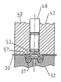
도 4는 기능성 부재를 판금부 내에 삽입하는데 사용된 프레스 또는 칼리퍼를 개방하기 전의 삽입 방법의 종료 단계의 도면.4 shows the end of the insertion method before opening the press or caliper used to insert the functional member into the sheet metal portion.
도 5는 도 4에 따른 삽입 방법의 종료 단계 후에 얻어진 최종 부품 조립체의 부분단면도.5 is a partial cross-sectional view of the final component assembly obtained after the end of the insertion method according to FIG. 4.
도 6은 헤드부의 직경이 샤프트부의 직경보다 더 큰 기능성 부재의 도면.6 is a view of a functional member in which the diameter of the head portion is larger than the diameter of the shaft portion.
도 7은 도 6에 도시된 부재의 조립 상태의 도면.FIG. 7 is a view of the assembled state of the member shown in FIG. 6. FIG.
도 8은 도 6과 유사하지만 헤드부의 직경이 샤프트부의 직경보다 더 작은 기능성 부재의 도면.8 is a view of the functional member similar to FIG. 6 but with a diameter of the head portion smaller than the diameter of the shaft portion;
도 9는 도 8에 도시된 부재의 조립 상태의 도면.9 is a view of the assembled state of the member shown in FIG. 8;
도 10은 도 1과 유사하지만 확대된 중공 부재의 도면.10 is a view similar to FIG. 1 but with an enlarged hollow member;
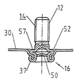
도 11은 너트 부재 형태인 본 발명에 따른 다른 기능성 부재의 종방향 부분단면도.11 is a longitudinal partial cross-sectional view of another functional member according to the present invention in the form of a nut member.
도 12는 도 11에 도시된 부재의 조립 상태의 도면.12 is a view of an assembled state of the member shown in FIG.
도 13은 스프링 클립을 수용하는 핀으로서 제조된 기능성 부재의 종방향 부분단면도.13 is a longitudinal partial cross-sectional view of a functional member made as a pin for receiving a spring clip.
도 14a는 튜브형 부재의 도면.14A is a view of a tubular member.
도 14b, 도 14c 및 도 14d는 도 14a에 따른 튜브형 부재를 나사 실린더가 손상되는 것을 염려할 필요없이 판금부 내에 삽입하기 위하여 설계된 변형 세팅 헤드의 도면.14B, 14C and 14D are views of a deformation setting head designed for inserting the tubular member according to FIG. 14A into a sheet metal part without having to worry about damaging the screw cylinder.
도 14e는 완성된 부품 조립체의 도면.14E is a view of a finished component assembly.
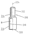
도 15는 도 1과 유사한 본 발명에 따른 부재의 다른 실시예의 축방향 부분단면도로서, 상기 부재는 도 16 내지 도 18에 따른 본 발명에 바람직한 다이 및 공정 기술에 관한 다음 설명에 사용된다.FIG. 15 is an axial partial cross-sectional view of another embodiment of a member according to the invention similar to FIG. 1, which member is used in the following description of preferred die and processing techniques for the invention according to FIGS. 16 to 18.
도 16a는 본 발명에 따른 다이의 축방향 단면도.16A is an axial cross-sectional view of a die in accordance with the present invention.
도 16b는 도 16a에 도시된 다이를 화살표 B 방향에서 바라본 단면도(端面圖).FIG. 16B is a sectional view of the die shown in FIG. 16A as seen from the arrow B direction. FIG.
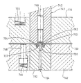
도 17a 내지 도 17h는 본 발명에 따른 기능성 부재를 본 발명에 따른 바람직한 다이를 사용하여 부착하는 본 발명에 따른 바람직한 방법을 도시하는 도면.17a-h show a preferred method according to the invention for attaching a functional member according to the invention using a preferred die according to the invention.
도 17i는 완성된 부품 조립체의 부분단면도17I is a partial cross-sectional view of a completed component assembly.
도 18a 내지 도 18c는 도 17에 따른 방법을 사용하는 것이 바람직한 본 발명에 따른 플런저 장치의 바람직한 실시예의 도면.18a to 18c show a preferred embodiment of the plunger device according to the invention, preferably using the method according to FIG. 17.
도 19는 본 발명에 따른 부재를 샌드위치형 구성품에 부착하는 것을 도시하는 부분단면도로서, 상기 부재 및 구성품은 부재를 중앙 종축의 좌측 상에 부착하기 이전과 부재를 중앙 종축의 우측 상에 부착한 이후의 상태로 도시되어 있다.19 is a partial cross-sectional view illustrating attaching a member according to the invention to a sandwich component, wherein the member and the component are attached before and after attaching the member on the left side of the central longitudinal axis and after the member is attached on the right side of the central longitudinal axis. It is shown in the state of.
도 20은 도 19에 도시된 도면과 유사하지만 변형된 종류의 판금부를 가진 개략도. FIG. 20 is a schematic view similar to that shown in FIG. 19 but with a sheet metal part of a modified type;
도 1에 도시된 기능성 부재는 수나사(12)가 형성된 샤프트부(14) 및 상기 샤프트부(14)의 나사 실린더와 외경이 적어도 실질적으로 동일한 중공의 헤드부(16)를 포함한다.The functional member shown in FIG. 1 comprises a
중공의 헤드부(16) 내에 위치된 원통형의 중공 공간(18)은 샤프트부(14)로부터 멀리 떨어진 헤드부(16) 말단(20)으로부터 나사 실린더 바로 하측까지 연장되어 이곳의 횡방향 벽(22)에서 종료된다. 여기서 중공 공간(18)은 구멍(bore) 형태를 갖는다. 횡방향 벽(22)의 형상은, 중공 공간(18) 및 횡방향 벽(22)이 한 가지 가능성은 되더라도 트위스트 드릴(twist drill)로 당연히 제조되어야 할 필요는 없지만, 트위스트 드릴로 제조된 구멍의 베이스에 대응한다. 중공 공간 및 횡방향 벽은, 예를 들면, 냉간 성형 공정에 의하여 제조될 수 있다. 본 명세서에서는 볼트 부재로 이해되는 기능성 부재(10)의 종축이 도면 부호(24)로 표시되어 있다.The cylindrical
부재(10)는 독일특허 DE PS 34 47 006 C2에 따른 기능성 부재의 피어싱 및 리벳팅 섹션의 대응하는 말단과 정확하게 동일한 말단(20)에 제조되고, 즉 이 말단은 내부 커팅면(26) 및 둥글게 된 외부 펀칭 및 드로잉 에지(28)를 갖는다.The
도 1에서, 커팅면(26)은 매우 작게 제조된다. 그러나, 일반적으로는 도 11에 따른 실시예의 원뿔형 커팅면(426)에 따라 제조된다.In Fig. 1, the cutting surface 26 is made very small. However, it is generally manufactured according to the
도 2, 도 3 및 도 4는 도 1에 따른 기능성 부재(10)를 판금부(30) 내에 삽입하는 3가지 상이한 단계를 도시한다. 삽입 방법은 종래의 바람직한 실시예를 상세하게 나타내는 도 15 내지 도 18의 도면을 참조하여 보다 상세하게 후술한다. 본 명세서는 관심을 가진 사람들의 이해를 도우려는 것이다.2, 3 and 4 show three different steps of inserting the
도 2에 도시된 바와 같이, 판금부(30)는 독일특허 DE PS 34 47 006 C2에 따른 대응하는 다이의 플런저 돌출부에 따라 설계된 중앙으로 배치된 원통형 플런저 돌출부(34)가 구비된 다이(32)의 바닥에 지지된다. 상기 플런저 돌출부는 판금부(30)로부터 멀리 떨어진 다이의 말단면(38)에 있는 직경이 큰 환형 리세스(40) 내로 합치되는 둥근 환형 함몰부(depression)(36)에 의하여 둘러싸인다. 다이(32)는 독일특허 DE PS 34 47 006에 기재된 다이(180)와 전체적으로 매우 유사하다.As shown in FIG. 2, the
다이(32)는 프레스(도시되지 않음)의 하단 공구에 위치된다. 판금부는 도시되어 있지는 않으나 세팅 헤드(44)의 원통형 외측 플런저(42)와 동심으로 배열되는, 예를 들면, 튜브형 지지 부재(tubular hold down member)에 의하여 다이의 말단면(38)에 맞대어 클램프된다. 즉, 판금부(30)는 환형의 리세스(40) 외측에 밀착되어 클램프된다. 기능성 부재(10)의 샤프트부는 세팅 헤드(44)의 원통형 안내 통 로(46)에 위치되는 반면, 헤드부(16)는 원통형 외측 플런저(48)로부터 돌출한다. 샤프트부(12)의 말단(29) 상에 압착되는 내측 플런저(48)는 튜브형 외측 플런저(42) 내에 동심으로 배열된다. 내측 플런저(48)는 각각의 기능성 부재를 삽입하기 위하여 외측 플런저에 대하여 후방으로 인발될 수 있지만, 내측 및 외측 플런저(48, 42)의 상대 위치는 도 2, 도 3 및 도 4에 따른 공정 단계마다 일정하게 유지된다. 이것은 후술하는 장치에 적용된다.
도 2에 따른 공정 단계에서, 기능성 부재의 말단면(20)은 내측 플런저(48)의 압력으로 판금부를 다이(32)의 환형 리세스(40) 내로 압착하여 판금부(30) 내의 대략 원뿔형인 얕은 리세스로 인발한다. 도 2의 단계에서, 기능성 부재(10)의 헤드부(16) 말단의 커팅면(26)과 협동하는 플런저 돌출부(34)는 판금부로부터 패널 슬러그(50)를 절삭한다.In the process step according to FIG. 2, the
도 3에서는 내측 플런저(48) 및 외측 플런저(42)를 포함하는 플런저 장치(43)가 더 하측방향으로 이동하고, 부재(10)의 중공 헤드부의 자유 말단 영역은 다이 내의 둥근 환형의 함몰부 또는 롤면(roll surface)(36) 때문에 판금부 애퍼춰의 하측방향으로 인발된 림 둘레의 환형 리벳 플랜지(37) 내에 형성됨을 알 수 있다. 판금부의 구멍은 이 공정 단계에서 트럼펫의 마우스와 유사한 가장자리 영역을 갖는다.In FIG. 3 the
내측 플런저(48)와 외측 플런저(42)가 결합되어 하측방향으로 계속 이동하는 도중에, 헤드부(16)의 원통형 벽이 샤프트부(14)의 바로 하측 영역에 압착되므로, 도 4에서 알 수 있는 바와 같이, 환형의 폴드(52)가 형성된다. 한편으로는 외측 플런저(42)에 의하여 안내되고 다른 한편으로는 펀칭된 에지 및 패널 슬러그 때문에 부재가 압박됨으로써 도 4에 도시된 바와 같이 확실하게 변형된다.As the
도 2 및 도 3에서는 외측 플런저(42)가 기능성 부재의 종축(24)과 직각으로 연장되는 면을 가진 환형의 노우즈(56)를 자신의 말단(54)에 가지고 있음을 알 수 있다. 절대적으로 필요하지는 않지만 상기 환형의 노우즈(56)는 도 4에 따른 방법 단계에서 환형의 폴더 상에 압착되어 헤드부의 벽 소재가 헤어 그립처럼, 즉 180° 로 접히고 이렇게 형성된 2개 층의 소재가 서로 완전하게 접촉되도록 완전한 폴드가 확실하게 만들어진다. 또한, 이러한 방식으로 형성된 링 폴더의 환형면(57)이 환형의 노우즈로 인하여 판금부(30)의 평면 약간 하측에 확실하게 위치된다. 이로써, 이러한 방식으로 형성된 링 플랜지(52)가 공지된 부재의 개시 단계에 이미 존재했었던 플랜지 기능을 갖는다. 또한, 환형의 노우즈(56)로 인하여 소재 패키지가 기능성 부재의 중공의 헤드부(16)의 폼로크된 영역에서 축방향으로 판금부(30)에 확실하게 압착됨으로써 매우 안정적이며 강한 방식으로 제조된다. 선택적으로 환형의 노우즈(56)는 한편으로는 판금부(30)와 회전을 방지하는 안전성을 향상시키는 중공의 헤드부(16) 사이에 상호연결된 선택 장치로 되는 성형부가 구비될 수 있고, 다른 한편으로는 예를 들면 노우즈가 도 4 및 도 5의 환형의 폴더의 상단 환형면에 형성되어 예를 들어 기능성 부재가 접지 연결 부재로 사용될 때 양호한 전기 접촉이 확실하도록 설계될 수 있다. 회전을 안전하게 방지하는 이러한 유형의 실행 방법의 대안으로서, 부재는 판금부에 접착제로 또한 결합될 수 있다. 예를 들면, 기능성 부재(10)는 이 기능성 부재가 판금부에 부착될 때 압력으로 단지 작용 하는 헤드부(16) 영역에 감압성 접착제로 코팅될 수 있다.2 and 3, it can be seen that the
도 4의 단계에서, 기능성 부재(10)를 판금부(30) 내에 삽입하는 단계가 완료된다. 프레스를 개방하고 이러한 방식으로 생산된 부품 조립체가 도 5에 도시된 형상을 가진 것을 알 수 있다.In the step of FIG. 4, the step of inserting the
본 명세서에서, 다이(32)는 프레스의 하단 공구에 배열된 다이로 처음에는 추측되었다. 이 경우, 세팅 헤드(44)는 프레스의 상단 공구 또는 프레스의 중간 플레이트 중 어느 한 곳에 고정된다. 그러나, 다이(32)는 중간 플레이트 상에 균등하게 배열된 다음 프레스의 하단 또는 상단 공구 상에 배열된 세팅 헤드와 협동할 수 있다. 또한 다이(32)를 공구의 상단 플레이트에 부착하고, 세팅 헤드를 중간 플레이트 또는 공구의 하단 공구에 장착할 수 있다. 또한, 세팅 헤드(44) 및 다이(23)는 로봇에 의하여 서로 압착될 수 있고 또는 다른 장치에 의하여 함께 결합될 수 있다.In the present specification, the
다음에 도 6 내지 도 13을 참조하면 본 발명에 따른 기능성 부재의 상이한 양태가 도시되어 있으며 이를 상세하게 후술한다. 다음 모든 예에서, 명료하게 나타내기 위하여 베이스 부재(100)를 각 실시예에서 연속적으로 증가시킨 것을 제외하고는 도 1 내지 도 5와 동일한 도면부호를 사용하였다. 그러나, 동일한 두 개의 마지막 숫자로 나타낸 특징부는 도 1 내지 도 5에 따른 실시예와 동일하거나 또는 대응하는 기능을 항상 갖는다는 점을 이해할 것이다. 이러한 특징부는 상이한 양태가 특별히 중요한 경우에만 별도로 설명한다.6 to 13, different embodiments of the functional member according to the present invention are shown and described in detail below. In all of the following examples, the same reference numerals as in Figs. 1 to 5 were used except for increasing the base member 100 in each embodiment for clarity. However, it will be appreciated that features represented by the same two last digits always have the same or corresponding function as the embodiment according to FIGS. 1 to 5. These features are described separately only where different aspects are particularly important.
도 6은 기능성 부재(110)의 헤드부(116)가 샤프트부(114)와 동일한 직경을 갖는 것이 절대적으로 필요한 것은 아니라는 점을 나타낸다. 도 6의 중공의 헤드부는 샤프트부(114)보다 직경이 더 크다. 또한, 기능성 부재(110)는 개시 단계에서는 실제 플랜지를 갖지 않는다. 플랜지는, 도 1 내지 도 5에 따른 제1 실시예와 관련하여 기재되고 도 7에 도시된 바와 같이, 기능성 부재(110)를 판금부 내에 삽입하는 동안에만 형성된다.6 shows that it is not absolutely necessary for the
다음에 도 7은 도 6에 도시된 기능성 부재(110)의 조립된 상태를 도시한 도면이다. 도 5에 따른 실시예에서와 같이 환형의 폴더(152)가 플랜지를 형성한다는 점을 이 도 7에서 명백히 알 수 있다.Next, FIG. 7 is a view showing an assembled state of the
도 8에 도시된 실시예에 있어서, 헤드부(216)의 외경은 기능성 부재(210) 샤프트부(214)의 나사 실린더의 외경보다 더 작다. 상기 실시예에서의 기능성 부재(210)도 또한 처음에는 판금부와 접촉되는 플랜지가 없다. 그럼에도 불구하고 플랜지는 기능성 부재를 판금부 내에 삽입하는 동안 중공의 헤드부(216)의 압착 때문에, 도 9에서 알 수 있는 바와 같이, 환형의 폴드(252) 내에 형성된다.In the embodiment shown in FIG. 8, the outer diameter of the
도 10은 기능성 부재(310)가 튜브 형태로 또한 제조될 수 있다는 점을 도시한 도면이다. 도 10에 도시된 기능성 부재(310)는 샤프트부(314) 또한 중공이 되도록 실제로 제조된다. 이러한 기능성 부재는 튜브형 섹션으로부터 문제없이 제조될 수 있다는 특정의 장점을 가지며, 중공 공간(318) 영역에 있는 튜브의 구멍(B)의 도 10에 도시된 연장부는 예를 들면 냉간 성형 도중이나 또는 대응하는 외측 몰드 내부에서의 고압 성형 처리 중에 어떠한 문제없이 제조될 수 있다. 도 10에 도시된 기능성 부재(310)의 수나사(312)는, 전술한 다른 예에서와 같이, 일반적인 나 사 형성 공정으로 제조될 수 있지만, 몰드 내부에서의 고압 성형 공정에 의하여서도 또한 제조될 수 있다. 이것은, 필요한 내부의 고압이 튜브의 종방향 모든 영역 또는 기능성 부재의 길이에 대응하는 튜브 길이에 문제없이 튜브의 끊이지 않는 중공의 내부 공간을 거쳐 도입될 수 있기 때문에, 튜브형 섹션 또는 튜브형 섹션 일부를 초기 소재로 사용함으로써 가능하다.10 shows that the
판금부 내에 끼워진 상태에서, 헤드부(316)와 막판 부품의 폼로크 조인트부는 도 5에 따른 전술한 실시예에 대응한다.In the state of being fitted in the sheet metal part, the
도 11은 도 10의 실시예와 유사한 다른 실시예의 도면이며, 이 경우 부재에는 암나사(412)가 형성된다.FIG. 11 is a view of another embodiment similar to the embodiment of FIG. 10, in which case a
도 12는 도 11에 따른 기능성 부재의 조립된 상태의 도면이다. 중공의 헤드부(416)는 전술한 실시예와 정확하게 동일한 방식으로 변형되고 - 이 경우의 차이는 환형 폴더(452)의 상단 환형면(457)은 판금부의 약간 상측에 배열된다. 그러나, 이것이 절대적으로 필요한 것은 아니다. 대응하는 면은 판금부(430)의 평면 하측이나 또는 판금부의 평면과 동일한 높이에 균등하게 배열될 수 있다.12 is a view of the assembled state of the functional member according to FIG. 11. The
또한 도 12에서는 패널 슬러그(450)가 리벳 플랜지(437) 영역의 중공 기능성 부재(410)의 중앙 통로를 폐쇄함으로써 이 지점이 밀봉된다. 그러나, 패널 슬러그는 또한 제거될 수도 있다.Also in FIG. 12 this point is sealed by the
도 12에 따른 실시예는 볼트 부재(도시되지 않음)가 기능성 부재(410) 내에 하측으로부터 나사로 조여질 수 있다는 특정의 장점을 갖는다. 이와 같이 하여, 환형의 폴더와 리벳 플랜지 및 이들 사이에 클램프된 판금부(430) 소재가 볼트를 조였을 때 함께 보다 밀착되고, 환형 폴더의 커다란 접촉면(480)이 매우 안정적으로 연결된다. 기능성 부재(410)가 이러한 볼트로서 사용되는 경우, 패널 슬러그(450)는 예를 들면 주된 피어싱 플런저에 의하여 다이의 중앙 통로 내로 압착되거나 또는 이 통로로부터 제거된다. 이러한 패널 슬러그를 이런 방식으로 제거하는 것은 이미 알려져 있다. 주된 피어싱 플런저는 이러한 경우 막판 부품을 사전에 천공하는데 사용된다.The embodiment according to FIG. 12 has the particular advantage that the bolt member (not shown) can be screwed from the bottom in the
다음에, 다이는 중공의 헤드부의 자유 말단을 대응하는 변형된 판금부 둘레에 단지 변형되도록 공지된 방식으로 제조된다. 즉, 다이는 도 2의 도면 부호(34)와 같은 플런저 돌출부 대신 중앙 구멍이 형성되어 제조된다. 그러나, 슬러그는 부재가 도 2에 도시된 바와 같이 삽입될 때 후속하는 작업에서 또한 제거될 수 있다.The die is then manufactured in a known manner so that the free end of the hollow head portion is only deformed around the corresponding deformed sheet metal portion. That is, the die is manufactured by forming a central hole instead of the plunger protrusion as shown by
도 13은 튜브 형태로 또한 제조될 수 있지만 나사가 없는 기능성 부재(510)의 도면이다. 대신에 이 기능성 부재는 스프링 클립(도시되지 않음)을 수용하는 외주 그루브(560)를 갖는다. 도 13에 도시된 기능성 부재(510)의 자유 말단(529)은 원뿔 형상으로 제조된다는 점을 또한 알 수 있다. 대응하는 스프링 클립은 이 원뿔면에 걸쳐 하측방향으로 압착된 다음 그루브((560) 내로 튀어 들어간다.FIG. 13 is a diagram of a
도 13에 도시된 기능성 부재(510)는 판금부 내에 이런 방식으로나 또는 약간 변형된 형태(예를 들면 외주 그루브(560)가 없이)로 삽입되어 핀 또는 원통형 스피것으로 사용될 수 있다. 또한 이것은 기능성 부재(510)의 중공 샤프트부(514)의 완성된 부품 조립체 내에 나사로 조여질 때 나사 자체에 형태를 만들거나 또는 절 단하는 나사산이 형성된 나사로 사용될 수 있다. 도 10, 도 11, 도 12 및 도 13의 실시예에 있어서, 중공의 헤드부(316, 416, 516)는 대응하는 샤프트부(314, 414, 514)의 외경보다 더 크거나 작은 직경을 용이하게 가질 수 있다.The
중공 샤프트부를 가진 실시예에 있어서, 내측 플런저(48)는 샤프트부의 중공의 내부 공간 내로 선택적으로 안내되어 압축 처리 도중에 기능성 부재를 안정되게 할 수 있다. 환형의 폴드를 형성하는데 바람직한 효과가 있는 이 처리는 도 14의 도 14b, 도 14c 및 도 14d에 도시되어 있다. 이를 위하여, 내측 플런저(648)는 직경이 중공의 샤프트부(614)의 내경(651)에 대응하는 저널형 돌출부(649)를 가지며, 이 돌출부(649)는 샤프트부의 환형 말단(629) 상으로 압착하는 환형 쇼울더(653)를 거쳐 내측 플런저의 상단부 내로 들어 간다.In the embodiment with the hollow shaft portion, the
도 14b 내지 도 14d에 따른 플런저 장치(643)의 외측 플런저(642)에는, 도 14c 및 도 14d에 대략적으로 도시된 바와 같이, 그 직경이 샤프트부(614)의 외측 나사산(612)의 직경에 대응하는 원통형 구멍이 제공될 수 있다.In the
내측 플런저(648)의 스피것형 돌출부(649)에도 불구하고, 이러한 장치는 소정의 상황하에서는 나사 실린더가 손상되거나 또는 나사 실린더가 압착될 수 있다. 도 14b에 도시된 이중 화살표는 가능한 교정 방법을 나타낸다. 이 교정 방법은 이중 화살표(655)에 대응하여 플런저가 세팅 헤드의 플런저 통로(646)를 통해 부재(610)를 삽입하는 것을 방해하지 않는 위치(657) 내로 부재(610)로부터 반경방향으로 멀리 떨어져 이동할 수 있는 적어도 두 개의 세그멘트로 분할되는 외측 플런저(642)로 구성된다. 두 개, 세 개 또는 그 이상이 될 수 있으며 대응하는 각도 범위(예를 들면 180°,120°, 등)를 갖는 이들 세그멘트는 자신의 반경방향 내측 상에 나사산 실린더(612)와 합치되는 형상부(659)가 형성됨으로써, 외측 플런저의 세그멘트가 종축(624)을 향하여 반경방향으로 폐쇄되도록 이동하는 도중에, 대응하는 나사산(659)의 나사산 세그멘트가 나사산 실린더(612)의 나사산과 결합되고 이렇게 하여 한편으로는 부재(610)에 축방향 힘을 전달하는 작용을 하며 다른 한편으로는 나사산 실린더에 임의의 압착이 가해지거나 손상되는 것을 방지한다. 이를 위하여, 나사산 세그멘트(659)의 설계는 나사산 실린더(612)의 설계와 상보적이 되도록 선택된다.Despite the spigot-shaped
도 14d에 따라 부재를 부착한 후. 외측 플런저(642)의 세그멘트를 다시 떨어지도록, 즉 종축(624)으로부터 반경방향 외측으로 멀어지는 방향으로 이동시킴으로써 외측 플런저(642)가 나사산 실린더를 손상시키지 않고 도 14e에 따라 완성된 부품 조립체를 제거하도록 상측방향으로 이동할 수 있다.After attaching the member according to FIG. 14d. By moving the segment of the
외측 플런저(642)의 세그멘트의 반경방향 이동에 대한 개념을 도 18에 따른 바람직한 실시예를 참조하여 상세하게 설명한다.The concept of radial movement of the segments of the
다음에, 도 15는 도 1에 도시된 기능성 부재(10)와 매우 유사하며, 횡방향 벽(722)을 형성하는 중공 공간(718)의 베이스가 여기서는 원뿔형 대신에 약간 오목하게 제조되며 부재(710)의 종축(724)과 실질적으로 직각으로 연장되어 일반적인 반경(723)을 거쳐 부재(710)의 헤드부(716)의 원통형 외벽 내로 들어간다는 것이 기본적으로 상이한 점이다. 횡방향 벽(722)을 형성하는 벽의 이러한 형상이 절대적으로 필요하지는 않지만, 이러한 형상으로 인하여 실질적인 예에서 샤프트부가 보다 양호하게 지지되고 이것이 안정적으로 연결되도록 작용한다.Next, FIG. 15 is very similar to the
도 16a 및 도 16b는 도 15에 도시된 기능성 부재를 삽입하는데 사용되는 것이 바람직한 다이의 도면이다. 이 다이(732)는 도 2에 따른 다이와 유사하지만, 특정한 차이가 있음을 알 수 있다. 예를 들면, 상기 실시예의 플런저 돌출부(734)는 종축(724) 방향으로 축방향 상측으로 연장되므로 플런저 돌출부(734)의 평탄면(735)이 다이의 말단면(733)의 약간 상측으로 돌출한다.16A and 16B are views of the preferred die used to insert the functional member shown in FIG. 15. This die 732 is similar to the die according to FIG. 2, but it can be seen that there are certain differences. For example, the
상기 실시예는 기능성 부재는 여전히 원뿔형 커팅면(726)을 갖도록 제조되지만, 헤드부(716)의 면(720)은 종축(724)과 직각이며, 예를 들면, 도 1의 둥근 부분(28)에서 둥글지 않은 환형면으로 간단하게 제조된다는 것이 장점이다. 이렇게 함으로써 기능성 부재의 제조 시 제조 단계가 감소된다. 다이(732)의 환형 리세스(740)는 도 2에 따른 다이(32)의 환형 리세스(40)와 원칙적으로 설계가 유사하지만, 도면 부호(737)로 도시된 바와 같이, 말단면(733) 내로의 전이부에서는 볼록하게 둥글다. 또한, 복수의 경사진 그루브(739) - 도 16b에 도시된 바와 같이 상기 실시예에서는 이러한 그루브가 8개임 - 는 상기 둥근 전이부(737) 내에 가공되므로 반경방향으로 연장되는 노우즈(741)가 각각의 경우에 두 개의 인접하는 그루브(739) 사이에 형성된다.While the embodiment illustrates that the functional member still has a
그루브(739)는 단면 형상이 적어도 실질적으로 반원형이며 이들 사이의 노우즈(741)와 같이 둥글어서, 그루브가 판금부를 변형시키는 동안 이 판금부를 손상시키지 않는다. 이들 그루브(739) 및 노우즈(741)는 부재가 판금부에 대하여 회전하지 않도록 안정성을 증가시키는 작용을 한다.
The
도 17a 내지 도 17h는 도 16에 따른 다이(732)의 도면이며, 이 다이는 플런저 장치(743)을 사용하여 기능성 부재(710)를 판금부(730)에 부착하는데 사용된다.17A-17H are views of the
다이(732)는 자신의 상측(764)이 다이의 면(733)과 동일 높이로 배열된 프레스의 하단 공구(762)의 구멍(760) 내에 위치된다. 스프링에 의하여 상측으로 바이어스된 복수의 태핏(768)이 하단 공구(762) 내에 위치되어 프레스 내로 삽입하는 도중에 판금부(730)를 지지하지만, 프레스를 폐쇄할 때 지지 부재(770)에 의하여 가해진 힘 때문에 하측방향으로 압착되어 판금부(730)가 다이(732)의 말단면(733) 및 다이 영역의 하단 공구의 상측면(764)과 접촉하게 되고 지지 부재(770)와 다이(732) 또는 하단 공구(762) 사이에 이동할 수 없도록 클램프될 수 있다.The
이렇게 스프링 바이어스된 3개의 태핏(768)은, 예를 들면, 다이(732)의 중앙 종축을 중심으로 균등한 각도의 간격으로 배열되어 제공될 수 있고, 단면도로 인하여 단지 하나의 태핏(768)만 도시되어 있다. 다이의 중앙 종축은 기능성 부재(710)의 중앙 종축과 동축, 즉 함께 정렬되어 있다.The three spring-biased
지지 부재(770)는, 공구 제조 분야에 잘 알려진 다른 유형의 스프링이 또한 사용될 수 있지만, 여기서는 압축 코일 스프링으로 개략적으로 도시된 스프링(776)과 같은 스프링(772)에 의하여 판금부 방향으로 또한 바이어스된다. 지지 부재(770)는 플런저 장치(743)를 세팅 헤드 또는 이 세팅 헤드가 끼워지는 프레스 공구에 속할 수 있다. 따라서 스프링(772)의 상측 말단이 세팅 헤드 또는 공구에 맞대어 고정된다.The
상기 예에서, 3개의 스프링(772)이 중앙 종축(724)을 중심으로 균일한 각도 의 간격으로 또한 배열되어 지지 부재(770)가 이들 스프링의 힘으로 하측방향으로 균등하게 압착된다.In this example, three
도 17a는 판금부(730)가 프레스 내에 삽입된 후 지지 부재(770)가 판금부의 상측과 접촉되어 이 판금부가 상기 지지 부재와 태핏(768) 사이에 가볍게 클램프될 때 프레스의 폐쇄 동작이 개시되는 상태의 도면이다.17A shows that after the
플런저 장치(743)는 외측 플런저(742)와 내측 플런저(748)를 또한 포함하며, 내측 플런저(748)의 하측 말단(774)은 기능성 부재(710)의 상단면(729) 상으로 압착된다. 기능성 부재(710)의 헤드부(716)는 외측 플런저(742)로부터 적어도 실질적으로 완전하게 돌출하고, 베이스를 형성하는 횡방향 벽(722)은 외측 플런저(742)의 하단면(776)의 약간 상측에 배열된다는 점을 알 수 있다. 이와 반대로 기능성 부재(712)의 샤프트부(714)는 외측 플런저(742)의 내부에 완전하게 위치된다.The
상기 도면에서 하측 공구(762)는 프레스의 하측 공구를 나타내는 한편 세팅 헤드는 프레스의 상단 공구 또는 중간 플레이트 상에 고정되는 것으로 추측된다. 도 5의 설명 마지막 부분에 기재된 다른 장치 또한 가능하다.It is assumed in this figure that the
프레스가 계속해서 폐쇄될 때, 스프링 바이어스된 지지 부재(770)가 판금부(730)에 맞대어 강하게 압착됨으로써 스프링 바이어스된 태핏(768)이 하측방향으로 압착되어 판금부(730)가 지지 부재(770)와 다이의 하단 공구(762) 또는 면(733) 사이에 견고하고 이동하지 않게 클램프된다. 상기 예에서, 지지 부재(770)는 더 이상 하측방향으로 이동하지 않는다. 그러나, 프레스의 상단 공구 또는 프레스의 중간 플레이트는 프레스가 더 이동하여 폐쇄됨에 따라 하측방향으로 더 이동하고, 이로써 지지 부재(770)는 자신의 위치가 변하지 않고 압축 코일 스프링(772)은 더 압착된다.As the press continues to close, the spring
프레스가 더 이동하여 폐쇄될 때, 외측 플런저(742)는 도 17b의 단계에서 내측 플런저(748)와 함께 또한 압착되어 기능성 부재(710)의 하측 말단(720)이 다이(732)의 플런저 돌출부(734)와 협동하여 판금부(730)로부터 패널 슬러그(750)를 절단한다.When the press is moved further and closed, the
샤프트부(716)의 내경, 즉 중공 공간(18)의 직경은 플런저 돌출부(734)의 외경보다 약간 더 크다는 점을 알 수 있다. 또한 기능성 부재(710)의 하측 말단(720)은 패널 슬러그(750)의 분리에 의하여 형성된 판금부(730) 애퍼춰의 가장자리 영역(778)을 플런저(748)의 압력으로 다이의 환형 함몰부(732) 내로 압착함으로써 이 가장자리 영역(778)이 판금부(730) 내에 원뿔형 리세스를 형성한다.It can be seen that the inner diameter of the
도 17c에 따라 프레스가 더 이동하여 폐쇄될 때, 패널 슬러그(750)의 제거에 의하여 형성된 애퍼춰의 가장자리 영역(778)은 환형의 함몰부(736) 내로 더 압착되고, 기능성 부재(710)의 말단(720)은 환형의 함몰부(736)의 U자 형상의 베이스 영역에 도달하여 이 베이스 영역의 형상에 의하여 반경방향 외측으로 변형되려고 한다.When the press is moved further and closed in accordance with FIG. 17C, the
도 17d에 따라 프레스가 더 폐쇄되는 동안 계속해서 변형되어 말단(720)이 외측으로 환형 모양으로 감겨 가장자리 영역(778)의 하측 말단 둘레에 결합됨으로써 리벳 플랜지가 형성된다. 프레스가 더 이동하여 폐쇄되는 동안, 패널 슬러그(750)는 기능성 부재(710)의 샤프트부(716) 내에 축방향으로 항상 눌려진다. 프레스가 도 17e의 상태로 계속해서 폐쇄 이동할 때, 샤프트부(716)의 원통형 벽은 판금부(730)의 가장자리 영역(778)의 내부와 상측 및 샤프트부(14)의 천이부 하측 영역에서 반경방향 외측으로 확장되기 시작하고, 이로써 플런저 돌출부(734)의 면(735)의 영역에 위치된 헤드부의 벽이 여기로부터 반경방향으로 멀리 떨어지도록 이동하기 시작한다. 패널 슬러그(750)는 기능성 부재(710)의 샤프트부(14)를 향하는 방향으로 더 변위된다.Continued deformation while the press is further closed in accordance with FIG. 17D results in the
프레스가 더 이동하여 폐쇄될 때, 도 17f에 따른 상태에 도달하게 되고, 여기에서 플런저 돌출부(756)에 바로 인접한 기능성 부재(710)의 헤드부(716)의 벽에 확실한 킹크(kink)(728)가 발생한다.When the press is moved further and closed, the state according to FIG. 17F is reached, where a sure kink 728 is placed on the wall of the
프레스가 더 이동하여 폐쇄될 때, 킹크 위치(782) 하측에 있는 기능성 부재(10)의 헤드부(16)의 벽 영역은 환형의 폴드 또는 환형의 벌지(bulge)(752)로 형성된다. 외측 플런저(742)의 면(754)은 판금부(730)의 상단 상으로 압착된다. 플런저 돌출부(756)가 링 폴드(752)의 상단을 편평하게 압착하여 이 링 폴드면이 판금부(730)의 상단 면 약간 하측에 배열되고 또한 종축(724)과 직각으로 된다. 패널 슬러그(750)는 기능성 부재(10)의 헤드부(16)의 중공 공간(718)의 말단에 도달하여 링 폴드(752)를 내부로부터 지지한다. 프레스가 도 17g에 따른 상태로 완전하게 폐쇄된다. 이렇게 하여 기능성 부재(710)를 판금부(730) 내로 삽입하는 단계가 완료된다.When the press is moved further and closed, the wall area of the
판금부 소재 및 기능성 부재(10)의 헤드부(16) 소재는 플런저 돌출부(756)에 의하여 환형의 폴드를 핀칭함으로써 다이(732)의 그루브(739) 및 노우즈(741) 영역 에서 변형되므로 판금부 소재가 기능성 부재의 소재와 걸리게 되어 회전이 양호하게 방지된다.The sheet metal part and the
프레스를 도 17h에 도시된 바와 같이 다시 개방시킨다. 태핏(768)이 판금부를 압착하여 부착된 기능성 부재가 하측 공구(762)로부터 멀리 떨어져서 판금부를 부착된 기능성 부재와 함께 다이(732)로부터 들어 올린다. 프레스를 더 개방시키면 기능성 부재(710)의 샤프트부(714)가 플런저(742)로부터 제거된다. 기능성 부재가 부착된 판금부는 프레스로부터 제거되어 도 17i에 도시된 바와 같이 나타난다.The press is opened again as shown in FIG. 17H. The
내측 플런저(748) 및 외측 플런저(742)는 프레스가 도 17h까지도 포함하여 도 17a 내지 도 17g의 상태로부터 완전하게 이동하여 폐쇄되는 동안 서로 동기식으로 이동한다는 점을 알 수 있다. 예를 들면, 이것은 외측 플런저(742) 상측의 직경보다 더 큰 헤드부를 갖는 내측 플런저에 의하여 달성될 수 있으며, 이 헤드부가 외측 플런저(742)와 접촉하게 되어 이들 두 부품의 상대 이동이 이 포인트 상에 위치되는 것이 방지된다. 그러나, 내측 플런저(748)는 외측 플런저(742)에 대하여 여전히 상측방향으로 이동할 수 있으므로 기능성 부재(710)가 내측 플런저(742)의 플런저 통로 내에 삽입될 수 있다.It can be seen that the
도 18은 도 17에 따른 플런저 장치(743) 대신에 바람직하게 사용될 수 있는 가능한 다른 플런저 장치(842)를 상세하게 나타낸 도면이다.FIG. 18 is a detailed illustration of another
외측 플런저(842)에는 종축(824')과 동축으로 배열되며 내측 플런저(848)를 변위가능하게 수용하는 내측 구멍(886)이 제공된다. 공급 통로(888)가 도 18a의 단면도의 우측 상에 도시되어 있고, 이 통로를 통해 기능성 부재(810)가 공급 장치(도시되어 있지 않음)로부터 구멍(886)에 의하여 형성된 플런저 통로 내에 삽입될 수 있다. 도 18a에 도시된 기능성 부재는 횡방향 벽의 베이스가 원뿔형 설계를 하고 있는 도 1에 따른 기능성 부재의 형상을 대략 갖고 있지만, 도 15 또는 도 17에 따른 기능성 부재(710) 외에 기본적으로는 전술한 기능성 부재 모두가 사용될 수 있다. 각각의 기능성 부재의 종축(824)은 플런저(886)의 종축(824')과 평행이며 각각의 기능성 부재는 서로 접촉되는 열로 배열된다는 점을 알 수 있다. 그러나, 플런저 통로(886)의 크기 때문에, 한 번에 단지 하나의 기능성 부재만 플런저 통로(886) 내에 위치될 수 있다.The
프레스가 개방되었을 때, 외측 플런저(842)는 내측 플런저(848)의 말단면(874)이 공급 통로(888)의 상측 경계의 레벨에 대략 도달할 때까지 대응하는 스프링의 압력으로 내측 플런저(848)에 대하여 하측방향으로 변위되어 기능성 부재(810)가 화살표(890) 방향의 압력에 의하여 플런저 통로(886) 내에 삽압될 수 있다.When the press is open, the
상기 실시예의 외측 플런저(843)는 복수의 부품으로 제조되고, 나사(도시되지 않음)에 의하여 상단부(894)에 고정된 환형의 하단부(892)를 포함한다. 하단부(892)는 원뿔형 영역(898) 내에 들어가는 원형 원통형 형상의 환형 벽(896)을 가진 중앙 애퍼춰(895)를 갖는다. 원형 원통형 영역(896) 및 원뿔형 영역(898)은 종축(824')과 동축으로 배열된다. 외측 플런저(886)의 상단부(894)에는 환형 쇼울더(902)를 거쳐 플런저 통로(886) 내로 들어가는 원뿔형 리세스(900)가 제공된 다. 원뿔형 영역(900) 및 환형 쇼울더(902)는 플런저 장치의 종축(824')과 동축으로 또한 배열된다.The
상기 실시예에 있어서, 종축(824')을 중심으로 균등한 각도의 간격으로 배열된 이들 세그멘트(904)는 플런저 장치(842)의 상단부(894)와 하단부(892) 사이의 영역에 위치된다. 단지 2개만 도 6에서 알 수 있는 3개의 세그멘트(904)는 각각의 기능성 부재(810)에 대한 종축(824')과 동축으로 배열된 리시버(905)를 함께 형성한다. 반경방향 내측으로 향하는 세그멘트(904)의 하단면(908)은 기능성 부재(810)의 샤프트부(814)의 나사산 실린더(812)와 상보적이 되도록 설계된 나사산 실린더의 세그멘트로서 제조된다. 반경방향 내측으로 향하는 세그멘트(904)의 상단면(912)은 각각의 기능성 부재(810)의 헤드부(816)의 외경보다 약간 작은 직경를 가진 통로(913)를 함께 형성한다. 세그멘트(904)의 반경방향 외측면(914)은 외측 플런저(842)의 상단부(894)의 대응하는 리세스의 원뿔형 면(900)과 상보적인 부분적으로 원뿔형인 면으로 설계된다. 세그멘트(904)의 반경방향 상측면(916)은 환형 쇼울더(902)와 상보적이 되도록 설계되어, 도 18a의 위치에서, 세그멘트(904)의 부분적으로 원뿔형인 면(914) 및 부분적으로 원형인 면(916)이 외측 플런저(843)의 각각의 대향하는 면, 즉 원뿔형 리세스(900) 및 환형 쇼율더(902)의 면과 완전하게 접촉된다.In this embodiment, these
상기 위치에서, 세그멘트(904)에 의하여 형성된 관통로(913)는 기능성 부재(810)의 헤드부(16)의 외경보다 직경이 더 작도록 제조된다. 이와 같이 하여, 각각의 기능성 부재(810)는 세그멘트 사이에 초기에는 들어가지 않고, 도 18a에 도 시된 바와 같이 세그멘트(904)의 상측 말단에 지지된다.In this position, the through
각각의 세그멘트(904)의 상단 영역은 부분적으로 원뿔형인 면(920)을 거쳐 부분적으로 원통형인 벽(922) 내로 들어 간다. 세그멘트(904)의 부분적으로 원뿔형인 면(920)은 도 18a에 따른 위치의 플런저 장치(842)의 하단부(892)의 원뿔형 면(898)과 대향하며 이들과 이격된다. 세그멘트(904)의 부분적으로 원통형인 면(922)은 플런저 장치(843)의 하단부의 부분적으로 원통형인 면(896)과 대향하며 각각의 경우 이들과 반경방향으로 이격된다.The top region of each
세그멘트(904)가 도 18a의 시작 위치로 항상 확실하게 복귀하도록, 스프링(926)에 의하여 바이어스된 태핏(928)이 제공되며, 이 태핏의 축(930)은 플런저 장치(843)의 종축(824')에 대하여는 경사지고 플런저 장치(843)의 하단부(892)의 원뿔형 면(898)과는 직각이다. 스프링 바이어스로 인하여 태핏(928)은 프레스가 개방되었을 때 세그멘트(904)의 부분적으로 원뿔형인 면(922)에 맞대어 압착되어 이들이 도 18a에 도시된 위치에 항상 있도록 직접 접촉된다. 스프링 바이어스는 그렇게 강하지 않다.A
프레스가 폐쇄된 경우, 내측 플런저(848)는 외측 플런저에 대하여 하측방향으로 압착되며 이 공정에서 플런저 통로(886)에 위치된 각각의 기능성 부재(810)가 세그멘트(904)의 상단면에 맞대어 압착된다. 통로(913)의 경사진 입구 및 각각의 기능성 부재(810)의 하단면(820) 영역의 대응하는 경사진 외측면으로 인하여, 내측 플런저(848) 상에 가해진 힘이 충분하여 세그멘트를 축방향(824')으로 반경방향 하측으로 및 반경방향 외측으로 압착하여 이들 세그멘트가 부분적으로 원뿔형인 면(920)이 외측 플런저(843)의 하단부(892)의 원뿔형 면(898)과 접촉될 때까지 핀(928)을 압착한다.When the press is closed, the
세그멘트(904)가 반경방향 외측으로 이동함으로써 이들 세그멘트에 의하여 경계를 이루는 통로(913)의 내경이 증가되어 플런저 통로(886)에 위치된 각각의 기능성 부재가 내측 플런저(848)의 힘으로 세그멘트(904) 사이의 통로 내로 압착된다. 이 동작의 중간 단계가 도 18b에 도시되어 있고, 이 동작은 수나사(812)가 형성된 각각의 기능성 부재(810)의 상측 샤프트부(814)가 세그멘트(904)의 하측 영역에 위치될 때까지 계속되고, 이 때 세그멘트가 핀(928)을 바이어스하는 스프링(926)의 힘으로 반경방향 내측으로 및 상측으로 이동하여 세그멘트(904)의 반경방향 내측으로 향하는 하측면의 나사산 세그멘트가 기능성 부재(810)의 나사 실린더(812)와 폼로크 방식으로 결합된다. 이 상태가 도 18c에 도시되어 있고, 내측 플런저(848)의 상단부보다 더 작은 외경을 가진 내측 플런저(848)의 정면부는 세그멘트(904)에 의하여 형상된 통로(913) 내부에 폼로크 방식으로 배열되며, 이것은 중심을 잡는데 바람직하다. 도 18c에 도시된 기능성 부재는 도 15a의 기능성 부재와 비교가능한 위치에 도달하고, 부재를 삽입하는 피어싱 공정이 개시되어 도 17에 따라 진행된다.As the
도 18에는 도시되어 있지 않지만, 내측 플런저(848)는 도 18c에 도시된 것보다 임의로 더 하측방향으로 이동할 수 없도록 배열된다. 예를 들면, 이것은 내측 플런저(848)의 상단부에 의하여 도 18c에 따른 최하단 위치의 플런저의 외측부(842)와 접촉되는 헤드가 형성되는 것을 방지할 수 있다. 프레스의 전체 힘 이 내측 플런저(848)를 거쳐 기능성 부재(810)의 면(829)으로 전달되고 외측 플런저(842)및 세그멘트(904)를 거쳐 기능성 부재의 나사산(812)으로 전달된다. 이러한 방식으로 나사산이 세그멘트(904)의 상보적인 나사 내부에 폼로크 방식으로 수용될 때 확실하게 손상되지 않을 수 있다. 기능성 부재의 샤프트부(814)를 중공으로 제조하는 경우, 내측 플런저(848)의 원통형부(930)는 이에 맞추어 설계될 수 있고 기능성 부재(810)의 말단(829) 상을 압착하는 환형의 쇼울더(도시되지 않음)를 거쳐 샤프트부의 내측 구멍 내로 연장되어, 이 부재가 내측 플런저의 연장된 돌출부에 의하여 지지될 때, 압착하는 힘이 이 부재를 중공 샤프트부의 벽과 함께 압착에 의하여 임의의 손상을 입지 않고 기능성 부재(810)에 전달될 수 있다.Although not shown in FIG. 18, the
세그멘트(904)의 개수는 3개로 제한되지 않는다는 점을 유의해야 한다. 그러나, 상기 실시예를 실시하는데 필요한 최소 개수는 2개, 3개, 4개 또는 그 이상이며 바이어스 스프링(926)을 가진 각각 하나의 핀(928)이 각각의 부재에 제공되는 것이 바람직하다.It should be noted that the number of
세그멘트(904)의 하측 말단에는 원하는 경우 도 17의 플런저 돌출부(756)를 함께 형성하는 노우즈(956)가 제공될 수 있다.The lower end of
도 17에 따라 기능성 부재(810)를 부착한 후, 프레스를 다시 개방하고 탄성이 줄어든 지지 부재가 기능성 부재가 부착된 판금부 상에 힘을 가하며, 상기 힘은 세그멘트(904)를 도 18b에 도시된 위치로 인발하는데 충분하여 샤프트부(814)를 릴리스시킨다. 스프링(928)의 스프링 장력이 작기 때문에, 프레스가 개방될 때 부착된 각각의 기능성 부재(810)를 손상시키지 않고 기능성 부재가 릴리스된다.
After attaching the
부착된 기능성 부재(810)가 릴리스된 후, 프레스의 개방으로 인하여 스프링힘에 의하여 하측방향으로 바이어스된 외측 플런저(842)가 하측방향으로 압착되는 한편, 내측 플런저(848)는 이 내측 플런저(848)의 하측 말단면이 통로(888)의 상단 경계 레벨에 도달하는 개시 위치에 도달할 때까지 상측방향으로 인발되어, 새로운 부재가 화살표(890) 방향으로의 압력에 의하여 플런저 통로(886) 내로 도입된다. 다음에 작업 사이클이 새로운 판금부 및 새로운 기능성 부재(810), 즉 플런저 통로(889)에 위치된 기능성 부재로 시작된다.After the attached
공구 장치는 점진적인 공구 스테이션으로 될 수 있고, 여기에서 판금 스트립이 복수의 스테이션을 통과하여 복수의 작업이 실행될 수 있다. 그러나, 공구 장치는 매 스크로크마다 단일 작업 단계를 실행하는 피어싱 프레스에 사용될 수 있다. 공구 장치를 로봇 또는 다른 종류의 공구에 부착하는 것도 가능하다.The tool device may be a gradual tool station, in which a sheet metal strip passes through the plurality of stations so that a plurality of jobs can be executed. However, the tool device can be used in a piercing press that executes a single work step every stroke. It is also possible to attach the tool device to a robot or other type of tool.
본 발명에 따른 기능성 부재는 순수하게 판금부에만 사용되는 것은 아니라 복합 부품으로 이해될 수 있는 다른 여러 가지 부품에도 사용될 수 있다.The functional member according to the present invention can be used not only purely in the sheet metal part but also in various other parts which can be understood as a composite part.
이러한 부품은 중공 공간 또는 구멍을 가진 소재로 구성되는 깨지기 쉽거나 또는 탄성을 가진 부품인 경우가 종종 있다. 다음 소재가 부품을 제조하는데 사용되는 소재의 예를 든 것으로서, 특히 본 발명에 따른 기능성 부재에 끼워질 수 있는 깨지기 쉽거나 또는 유연한 부품이다.Such parts are often fragile or elastic parts consisting of a material having a hollow space or a hole. The following material is an example of the material used to make the part, in particular a fragile or flexible part that can be fitted to the functional member according to the invention.
금속 폼Metal foam
이들은 구멍 치수 및 분포가 제조 공정에서 한정된 값으로 설정될 수 있고 광범위하게 응용할 수 있는 구멍이 매우 많은 금속 소재이다. 또한 이러한 금속 폼은 소재 및 중량을 감소시킬 수 있으므로, 각종의 부품를 위하여 비용도 절감될 수 있다. 이들은 점진적인 변형을 통하여 충격 에너지를 흡수할 수 있으므로 사고 시 탑승자를 보호하기 위하여 충격 에너지를 흡수하는 차량 구조 부속품과 같은 에너지 흡수 부품용으로 사용될 수 있다. 또한, 이들은 감쇠 성질이 양호하여 음파 및 기계 진동을 용이하게 흡수 또는 경감시킬 수 있다.These are very porous metal materials that can be set to defined values in the hole dimensions and distribution in the manufacturing process and are widely applicable. In addition, since the metal foam can reduce the material and the weight, the cost can be reduced for various parts. They can absorb impact energy through gradual deformation and thus can be used for energy absorbing components such as vehicle structural accessories that absorb impact energy to protect occupants in an accident. In addition, they have good damping properties and can easily absorb or reduce sound waves and mechanical vibrations.
특히 알루미늄 또는 마그네슘으로 제조된 금속 폼 및 스틸로 제조된 금속 폼이 공지되어 있다. 이러한 금속 폼을 제조하는데 사용될 수 있는 상이한 제조 공정이 공지되어 있다. 예를 들면, 금속 파우더를 화학 혼합물과 혼합시킨 후 열처리로 금속 폼을 형성할 수 있다. 폼을 형성하는 가스는 금속의 융점에서 릴리스된다. 이러한 방식으로 가스가 97% 함유된 폼 알루미늄을 제조할 수 있다. 스틸 폼은 이러한 방법으로 제조될 수 있다. 이 공정은 광범위한 부재 및 합금용으로 사용될 수 있다. 또한 중공인 볼, 예를 들면 중공인 스틸볼을 사용하여 금속 구조체를 제조할 수도 있다.In particular metal foams made of aluminum or magnesium and metal foams made of steel are known. Different manufacturing processes are known that can be used to produce such metal foams. For example, the metal powder may be mixed with the chemical mixture and then heat treated to form the metal foam. The gas forming the foam is released at the melting point of the metal. In this way foam aluminum containing 97% gas can be produced. Steel foam can be produced in this way. This process can be used for a wide range of members and alloys. It is also possible to produce metal structures using hollow balls, for example hollow steel balls.
가스가 60% 함유된 마그네슘 폼을 제조하기 위하여, 얇은 벽으로 된 중공의 세라믹 볼을 주조 공정에서 마그네슘 매트릭스에 매입하는 것이 공지되어 있고, 마그네슘 합금 또한 사용될 수 있고 자유롭게 선택될 수도 있다.In order to produce 60% gas-containing magnesium foam, it is known to embed thin-walled hollow ceramic balls into the magnesium matrix in the casting process, and magnesium alloys may also be used and may be freely selected.
그러나 이러한 소재는 매트릭스 합금에 따라 초기 합급보다 더 단단하고 더 깨지기 쉽거나, 또는 더 유연하고 더 내구성이 강하게 할 수 있다.However, these materials can be harder and more brittle, or more flexible and more durable than the initial alloy, depending on the matrix alloy.
제조된 후에 폼은 여과재를 사용하여 제거 또는 유연하게 된 주물 스킨으로 할 수 있다. 충전재로 선택적으로 채워진 주물 스킨을 가진 폼이 일종의 샌드위치 구조체를 형성한다.After being prepared, the foam can be made into a casting skin that has been removed or plied using a filter medium. A foam with a casting skin optionally filled with filler forms a sandwich structure.
금속 폼을 가진 샌드위치 구조체Sandwich structure with metal foam
전술한 금속 폼은 주물 스킨을 갖거나 또는 갖지 않도록 하고, 스틸 금속 또는 플라스틱으로 제조된 상측 및/또는 하측 커버층을 갖도록 제조하여 금속 폼으로 제조된 코어를 가진 샌드위치 구조체 형태의 소재 복합물을 제조할 수 있다.The metal foams described above may be made with or without casting skins and have upper and / or lower cover layers made of steel metal or plastic to produce material composites in the form of sandwich structures having cores made of metal foams. Can be.
내 마모성, 낮거나 높은 마찰, 내 부식성 및 양호한 내구성과 같은 성질은 코어에 코팅 또는 코팅층을 가함으로써 달성될 수 있다. 대응하는 부품 또는 존재하는 임의의 커버층은 공지된 모든 코팅법, 즉 전기 도금 코팅, 래커 코팅 또는 특히 PVD법에 의하여 가해진 코팅을 사용하여 코팅될 수 있다. 판금층이 폼을 구성하는 코어에 제공될 때, 판금층은 금속 폼 코어에 풀로 부착되거나 또는 조인트될 수 있고, 납땜 즉 브레이징법 또한 가능하다. 일반적으로 풀을 사용하여 코어에 조인트시켜 플라스틱으로 제조된 층을 커버한다.Properties such as wear resistance, low or high friction, corrosion resistance and good durability can be achieved by applying a coating or coating layer to the core. The corresponding part or any cover layer present can be coated using all known coating methods, ie electroplating coatings, lacquer coatings or in particular coatings applied by the PVD method. When the sheet metal layer is provided to the core constituting the foam, the sheet metal layer may be glued or jointed to the metal foam core, and soldering or brazing is also possible. Generally, a paste is used to joint the core to cover a layer made of plastic.
샌드위치 구조체를 제조하는 다른 방법은 금속 또는 플라스틱을 예를 들면 압출 공정에서 금속 폼 코어를 완전하게 또는 영역별로 압출된 섹션 형태로 제조된 중공의 섹션을 제공하는 것이다. 이것은 기다란 폼 금속 스트립을 선택적으로 폼 금속의 조인트 면으로 섹션에 삽입하거나, 또는 금속/폼 혼합물을 중공 섹션에 폼형성함으로써 실행될 수 있다. 개방된 섹션 또는 형상을 가진 판금부에도 또한 폼 금속(한 개의 폼 금속으로 된 층 또는 복수의 폼 금속으로 된 층으로 제조된 인서트)으로 제조된 인서트가 제공될 수 있고, 다음에 용접, 리벳팅, 조인트 또는 그 외의 방법에 의하여 가장자리 영역의 개방된 섹션에 고정된 커버 스트립 또는 섹션 으로 커버될 수 있다. 플라스틱 폼 또는 이러한 복합 구조체의 다른 소재 또한 폼 금속 대신에 사용될 수 있다. 폼 금속 또는 복수의 충전재로 채워진 이러한 섹션의 구체적인 용도는 미리 조립된 섹션을 채우고, 선택적으로 벤딩 또는 프레싱에 의하여 후속으로 형상을 이루어 제조될 수 있는 자동차의 B 칼럼으로 사용된다.Another method of making a sandwich structure is to provide hollow sections made of metal or plastic, for example in the form of sections in which the metal foam core is extruded completely or zone-by-zone in an extrusion process. This can be done by inserting an elongate foam metal strip into the section, optionally with a joint face of foam metal, or foaming the metal / foam mixture into the hollow section. Sheet metal parts with open sections or shapes may also be provided with inserts made of foam metal (inserts made of one foam metal layer or a plurality of foam metal layers), followed by welding and riveting. It may be covered by a cover strip or section secured to an open section of the edge region by means of a joint, joint or otherwise. Plastic foam or other materials of such composite structures may also be used instead of the foam metal. The specific use of such sections filled with foam metal or a plurality of fillers is used as B columns of automobiles which fill pre-assembled sections and can subsequently be shaped and produced by bending or pressing.
원하는 기계적인 성질은 이러한 섹션을 섹션별로 충전함으로써 설정될 수 있다. 예를 들면, 원하는 강성 또는 버클링 강도는 하나의 영역에서 달성될 수 있고, 예를 들어 사고가 난 경우의 원하는 변형성은 다른 영역에서 달성될 수 있다.The desired mechanical properties can be set by filling these sections section by section. For example, the desired stiffness or buckling strength can be achieved in one area, for example the desired deformation in case of an accident can be achieved in another area.
다른 샌드위치 구조체Other sandwich structures
허니콤 구조체를 가진 코어 및 상단 및/또는 하단 커버층으로 이루어지는 소재 복합물 또한 사용될 수 있으므로, 커버층은 박판 또는 플라스틱 플레이트로 제조될 수 있다. 허니콤 구조체는 금속, 금속 포일 또는 판지 또는 종이 또는 플라스틱 또는 셀룰로오스 또는 링고-셀룰로오스로 제조될 수 있다.A material composite consisting of a core with a honeycomb structure and a top and / or bottom cover layer can also be used, so that the cover layer can be made of thin plate or plastic plate. Honeycomb structures can be made of metal, metal foil or cardboard or paper or plastic or cellulose or ringo-cellulose.
취성 파괴 특징을 가진 소재Material with brittle fracture characteristics
이러한 소재로는 예를 들면 마그네슘, 마그네슘 합금 및 열경화성 수지에 충전재를 채우거나 채우지 않고 제조된 주물을 포함한다. 또한 이러한 소재는 본 발명에 따른 기능성 부재 장치가 끼워진 부품용으로 사용될 수 있다.Such materials include, for example, castings made with or without fillers in magnesium, magnesium alloys and thermosetting resins. This material can also be used for parts fitted with the functional member device according to the invention.
다른 부품 소재 및 설계Other parts material and design
플라스틱 부품, 나무 또는 압축 판지 등으로 제조된 부품 또한 본 발명에 다른 부품 조립체용으로 사용될 수 있고, 이러한 소재는 일반적으로 리벳 결합으로 제조할 때 나타나는 힘으로 상당히 구부러질 만큼 유연한 것으로 생각되는 것이 일 반적이다.Parts made of plastic parts, wood or compressed cardboard, etc. may also be used for the assembly of other parts in the present invention, which is generally considered to be flexible enough to bend considerably with the forces that appear when manufactured with rivet bonds. to be.
전술한 소재 중 한 가지 이상의 복합물, 예를 들면 서로 조인트된 복수의 층을 포함하는 다층 장치로 구성되는 특수한 소재 복합물 또한 가능하므로, 예를 들면 더욱 두꺼운 부품 또는 보다 복잡한 형상을 가진 부품이 제조될 수 있다.Special material composites are also possible, which consist of a composite of one or more of the aforementioned materials, for example a multi-layer device comprising a plurality of layers joined together, so that for example thicker parts or parts with more complex shapes can be produced. have.
도 19 및 도 20은 본 발명에 따른 기능성 부재(1010)가 복합 부품(1030)에 사용될 수 있는 가능한 방법 두 가지를 도시하는 도면이다.19 and 20 illustrate two possible ways in which the
도 19는 초기 상태의 기능성 부재(1010)의 중앙 종축(1024)의 좌측 절반부의 도면이고, 기능성 부재(1010)의 다른쪽 절반부는 도시된 나사산 절반부를 가진 연속적인 나사산 실린더를 형성하는 것이 당연한 나사산을 제외하고는 종축(1024)의 다른쪽에 대칭으로 제조된다.19 is a view of the left half of the central
전술한 실시예와 달리, 플랜지(1011)가 샤프트부(1014)와 헤드부(1016) 사이에 제공되며, 도시된 바와 같이 회전 방지 작용을 하는 노우즈(1013)를 지지하는 것이 바람직하다. 회전 방지 작용을 하는 노우즈(1013)를 가진 플랜지(1011)는 원하는 경우 제공되지 않을 수도 있지만 여기서는 이 플랜지로 인하여 기능성 부재(1010)가 복합 부품(1030)에 더 안정적으로 부착된다. 복합 부품(1030)은 전술한 복합 부품 실시예 중 한 가지를 가질 수 있다.Unlike the embodiment described above, a
기능성 부재를 부착하기 전에, 복합 부품은 중앙 종축(1024)의 좌측에 도시된 바와 같이 준비된다.Before attaching the functional member, the composite part is prepared as shown to the left of the central
원통형 구멍(1031)이 구성품(1030)의 원형 원통형 벽으로 제조되고, 복합 부품(1030)의 상단층(1033)은 스웨이징된 리세스(swaged recess)(1035) 내에 형성된 다는 점을 알 수 있다. 구멍(1031)은 드릴링 공정 또는 피어싱 공정에 의하여 제조되는 한편, 스웨이지(1035)는 피어싱 단계, 예를 들면 피어싱 프레스에서 제조되는 것이 일반적이다. 구멍(1031) 및 스웨이지(1035) 양자 모두가 피어싱에 의하여 제조되는 경우, 이것은 대응하는 형상의 피어싱 공구에 의하여 한 단계로 제조될 수 있다. 스웨이지(1035)의 형상은 플랜지부(1011)의 형상과 유사하다.It can be seen that the
기능성 부재를 도 2에 따른 다이를 사용하여 부착시킬 때, 기능성 부재(1010)의 중공의 헤드부(1015)와 복합 부품(1030)의 하단층(1039) 사이에 폼로크 조인트가 형성된다. 이 조인트 형상은 도 5의 형상과 매우 유사하며, 중공의 헤드부(1016)는 자신의 말단 영역의 리벳 플랜지(1037)에 형성되고 이 리벳 플랜지(1037)는 복합 부품(1030)의 하단층(1039) 하측에 위치되며, 이 하단층(1039) 상측의 중공의 헤드부(1016) 영역에는 환형의 폴드(1052)가 형성된다. 환형의 폴드(1052)는 리벳 플랜지(1037)와 함께 U자형 환형 그루브를 형성하며, 여기에는 구멍(1031)이 이미 형성된 하단층(1039)의 가장자리 영역이 수용된다. 그러나, 환형의 폴드(1052)는 도 5의 실시예의 환형의 플랜지(52)만큼 그렇게 강하지 않다는 점을 알 수 있고, 이것은 이 영역이 상기 실시예의 외측 플런저의 응력을 받지 않을 수 있다는 것으로 이해될 수 있다. 또한, 상기 실시예는 복합 부품(1030)이 사전에 드릴링되기 때문에 패널 슬러그가 적다. 다시 말하면, 도 19의 기능성 부재(1010)의 하측 말단은 자체 피어싱 방식으로 하단층(1039)을 뚫지 않는다. 여기서는 패널 슬러그가 형성되지 않기 때문에, 둥근 환형 함몰부 또는 다이의 롤면을 도 2에 도면 부호(36)로 도시된 바와 같이 깊이 만들 필요가 없다.
When attaching the functional member using the die according to FIG. 2, a foam lock joint is formed between the hollow head portion 1015 of the
복합 부품(1030)이 다이 상에 하측으로부터 지지되고 기능성 부재(1010)가 플런저에 의하여 상측으로부터 하측방향으로 압착되기 때문에, 회전을 방지하도록 제공된 노우즈 및 특징부(1013)는 스웨이지(1035) 영역의 복합 부품의 상단층 상측 내로 압착된다. 기능성 부재가 부착된 후, 플랜지부(1011)의 상측(1041)은 복합 부품(1030)의 상단층(1033)의 상측(도 19 참조)과 대략 같은 높이로 된다. 복합 부품(1030)의 코어 소재는 환형 폴더(1052)의 연장부 및 환형 폴더(1052) 영역의 하단층(1039) 및 U자형 환형 그루브(1053)에 따라 변형된다,Since the
플랜지부(1011)가 제공되지 않은 경우, 스웨이지(1035)는 필요하지 않으며 준비된 구성품(1030)은 단지 원통형 구멍만 가지고 상단층의 원형 애퍼춰는 중공의 헤드부(1016)의 외경과 적어도 실질적으로 동일한 직경을 갖는 것이 바람직하다.If the
도 20은 도 19를 약간 변형시킨 실시예의 도면이다. 부품(1030)은 원통형 구멍(1031)을 만들어서 또한 준비되지만, 이 구멍(1031)은 복합 부품(1030)의 하단층(1039) 바로 상측에서 정지된다. 복합 부품(1030)의 상단층(1033)에는 스웨이지(1035)가 또한 형성되지 않는다. 구멍(1031)의 직경은 도19의 대응하는 부재와 동일한 기능성 부재(1010)의 중공의 헤드부(1016)의 외경에, 도 19에 따른 실시예에서와 같이, 적어도 실질적으로 대응한다.20 is a view of the embodiment slightly modified from FIG. The
상기 실시예에서, 기능성 부재(1010)의 하측 말단에는 대응하는 다이(도 2의 다이에 대략 대응함)와 협동하여 패널 슬러그(1050)를 스탬핑시키는 피어싱 특징부가 구비되고, 이 패널 슬러그는 보다 높은 위치에 배열된 다이의 중앙 포스트 때문에 중공의 헤드부(1016)의 횡방향 벽(1022) 영역의 중공의 헤드부(1016) 내로 압착 된다.In this embodiment, the lower end of the
리벳 플랜지(1037) 영역의 폼로크 조인트는 환형 폴더(1052)가 패널 슬러그(1050)에 의하여 내측에 추가로 지지되는 것을 제외하고는 기본적으로 도 19에 따른 실시예와 동일하게 형성된다.The foam lock joint in the region of the
복합 부품(1030)의 상단층(1033)에 스웨이지(1035)가 제공되지 않기 때문에, 기능성 부재의 플랜지부(1011) 하단쪽이 상단층(1033)의 상단쪽과 접촉한다. 이것은 특히 회전을 방지하는 노우즈부(1013) 영역을 약간 압착하여 회전이 방지되도록 원하는 안정성을 제공한다. 두 가지 예의 복합 부품(1030)은 플랜지부(1011)와 리벳 플랜지(1037) 사이에서 소정의 압축을 받고, 이것은 조인트의 품질 및 안정성 면에서 바람직하다.Since no
전술한 기능성 부재는 예를 들면 강도 등급 5.6에 도달하는 모든 소재로 제조될 수 있다. 이러한 금속 소재로는 탄소 함량이 0.15 내지 0.55%인 탄소강이 일반적이다.The aforementioned functional member can be made of any material which reaches, for example, strength class 5.6. As such a metallic material, carbon steel having a carbon content of 0.15 to 0.55% is generally used.
모든 실시예에 있어서, 모든 소재는 냉간 성형의 일부로서 ISO 규격의 등급 8의 강도값에 도달하는, 예를 들면 DIN 1654에 따른 35B2 합금이 기능성 부재의 소재의 예로서 또한 지칭될 수 있다. 이러한 방식으로 형성된 고정 부재는 특히 인발될 수 있는 판금부용의 시판 중인 모든 스틸 소재는 물론 알루미늄 또는 이들의 합금에 적합하다. 특히 고강도의 압루미늄 합금, 즉 AlMg5 또한 기능성 부재로 사용될 수 있다. In all embodiments, all materials can also be referred to as examples of the material of the functional member, for example a 35B2 alloy according to DIN 1654, which reaches a strength value of grade 8 of the ISO standard as part of cold forming. The fastening members formed in this way are particularly suitable for all commercially available steel materials for sheet metal parts which can be drawn, as well as for aluminum or alloys thereof. Particularly high strength aluminum alloys, ie AlMg 5 , can also be used as functional members.
현재까지 시도한 결과 소재 35B2를 사용했을 때, 헤드부의 반경방향 벽 두께와 헤드부의 외경 비율은 0.15 ~ 0.2 범위 내인 것을 알았다. 이들이 응력 힘 및 풀-아웃 힘을 증가시키기 때문에 값이 보다 높은 것이 바람직하다. 그러나, 힘으로 압착함으로써 허용가능하지 않을 정도로 변형되지 않도록 확실하게 해야 한다. 직경 8mm에서는 반경방향 두께가 1.2mm가 바람직한 것으로 판명되었다.
Attempts to date have shown that when the material 35B2 is used, the ratio of the radial wall thickness of the head to the outer diameter of the head is in the range of 0.15 to 0.2. Higher values are desirable because they increase stress forces and pull-out forces. However, it must be ensured that it is not deformed to an unacceptable extent by compressing with force. In the diameter of 8 mm, the radial thickness of 1.2 mm turned out to be preferable.
Claims (26)
Applications Claiming Priority (6)
| Application Number | Priority Date | Filing Date | Title |
|---|---|---|---|
| DE19932023.3 | 1999-07-09 | ||
| DE19932023 | 1999-07-09 | ||
| DE19935923.7 | 1999-07-30 | ||
| DE19935923 | 1999-07-30 | ||
| DE10018716.1 | 2000-04-16 | ||
| DE10018716 | 2000-04-16 |
Publications (2)
| Publication Number | Publication Date |
|---|---|
| KR20020037743A KR20020037743A (en) | 2002-05-22 |
| KR100637791B1 true KR100637791B1 (en) | 2006-10-23 |
Family
ID=27213801
Family Applications (1)
| Application Number | Title | Priority Date | Filing Date |
|---|---|---|---|
| KR1020027000344A KR100637791B1 (en) | 1999-07-09 | 2000-07-07 | Functional element, method for fixing it in a sheet metal part, assembling element and swaging assembly |
Country Status (11)
| Country | Link |
|---|---|
| US (1) | US7131807B1 (en) |
| EP (2) | EP1249305B1 (en) |
| JP (1) | JP4679777B2 (en) |
| KR (1) | KR100637791B1 (en) |
| AU (1) | AU6156600A (en) |
| BR (1) | BR0012334B1 (en) |
| CA (1) | CA2378812C (en) |
| DE (3) | DE10033149A1 (en) |
| ES (2) | ES2184718T3 (en) |
| MX (1) | MXPA02000041A (en) |
| WO (1) | WO2001003880A1 (en) |
Families Citing this family (22)
| Publication number | Priority date | Publication date | Assignee | Title |
|---|---|---|---|---|
| DE10033149A1 (en) * | 1999-07-09 | 2001-02-01 | Profil Verbindungstechnik Gmbh | Functional element with hollow head part having same outer diameter as shank and formed with swaging and riveting features to fit into metal plate |
| US7731467B2 (en) | 1999-07-09 | 2010-06-08 | Profil Verbindungstechnik Gmbh & Co., Kg | Bolt element having a shaft part and a spherical head, component assembly and method for the manufacture of a bolt element |
| DE10015239A1 (en) * | 2000-03-27 | 2001-10-04 | Profil Verbindungstechnik Gmbh | Functional element arrangement, functional element, auxiliary joining part, assembly part and method for producing an assembly part |
| JP2001343010A (en) * | 2000-06-01 | 2001-12-14 | Shinjo Seisakusho:Kk | Drive bolt and built-up body of driver bolt |
| KR100908859B1 (en) | 2000-12-29 | 2009-07-21 | 프로필 페르빈둥스테크닉 게엠베하 운트 컴파니 카게 | Bolt element comprising a shaft part and a spherical head, assembly component and a method for producing a bolt element |
| DE10114200A1 (en) | 2001-03-23 | 2002-09-26 | Profil Verbindungstechnik Gmbh | Fastener, for use with sheet metal, has annular head connected to tubular rivet section which has guide section at its base projecting below rivet section with annular gap between two sections |
| DE10243759B4 (en) | 2002-09-20 | 2011-08-11 | PROFIL Verbindungstechnik GmbH & Co. KG, 61381 | Method for producing an electrically conductive connection between an electrical connection device such as a cable lug and a sheet metal part, fastening element and assembly component |
| DE10117060A1 (en) * | 2001-04-05 | 2002-10-10 | Profil Verbindungstechnik Gmbh | Method for attaching a functional element to a component and associated tool |
| DE10118149A1 (en) * | 2001-04-11 | 2002-10-17 | Profil Verbindungstechnik Gmbh | Method to fasten functional element to sheet metal part uses die plate with and rivet part with self-punching action for secure connection |
| US6791051B2 (en) * | 2002-08-22 | 2004-09-14 | Delphi Technologies, Inc. | Method for metallurgically attaching a tube to a member |
| DE102004030223A1 (en) * | 2004-06-23 | 2006-01-12 | Profil Verbindungstechnik Gmbh & Co. Kg | Flat metal part to be stationary joined to module, comprising impressions serving as locking areas |
| DE102004043688A1 (en) | 2004-06-23 | 2006-04-06 | Profil-Verbindungstechnik Gmbh & Co. Kg | Method for producing an assembly part consisting of a sheet metal part and a functional element attached thereto, sheet metal part and functional element |
| KR100696537B1 (en) * | 2005-10-05 | 2007-03-19 | 삼성에스디아이 주식회사 | Chassis boss assembly and display apparatus comprising the said assembly |
| US8328489B2 (en) * | 2007-12-17 | 2012-12-11 | Acument Intellectual Properties, Llc | Self-pierce rivets and an adjustable strap handle |
| DE102009037427A1 (en) | 2009-08-13 | 2011-02-17 | Profil Verbindungstechnik Gmbh & Co. Kg | Functional element, method for introducing the functional element in a sheet metal part and assembly component |
| KR101214011B1 (en) | 2010-05-31 | 2012-12-26 | 로베르트 보쉬 게엠베하 | Structure of electrode terminal and secondary battery using the same |
| DE102011051137B4 (en) | 2011-06-17 | 2023-01-19 | Dr. Ing. H.C. F. Porsche Aktiengesellschaft | Body structure of a motor vehicle with a sheet metal part and a fastening element |
| DE102012008798B4 (en) * | 2012-03-31 | 2016-01-14 | Johnson Controls Gmbh | Method of joining and connecting element |
| DE102012215263A1 (en) * | 2012-08-28 | 2014-03-06 | BSH Bosch und Siemens Hausgeräte GmbH | Cooking appliance |
| CN105065406B (en) * | 2015-08-07 | 2017-12-12 | 珠海格力电器股份有限公司 | Riveted structure, riveting die set, riveting process and air-conditioning |
| US9701227B2 (en) * | 2015-10-08 | 2017-07-11 | Brose Fahrzeugteile Gmbh & Co. Kommanditgesellschaft | Assembly group of a vehicle seat comprising a tube element and an attachment part arranged thereon |
| TWI714898B (en) * | 2018-11-01 | 2021-01-01 | 達霆精密工業有限公司 | Control device |
Family Cites Families (27)
| Publication number | Priority date | Publication date | Assignee | Title |
|---|---|---|---|---|
| US2071507A (en) * | 1935-04-29 | 1937-02-23 | Scovill Manufacturing Co | Method of applying fasteners to sheet like material |
| GB1205744A (en) * | 1966-10-12 | 1970-09-16 | Linread Ltd | Improvements in or relating to tubular fasteners |
| US3624867A (en) * | 1968-09-20 | 1971-12-07 | Amp Inc | Plastic locking nut in strip form |
| GB1341654A (en) * | 1972-03-02 | 1973-12-25 | Playart Ltd | Battery powered toys or models |
| US4039099A (en) * | 1976-02-11 | 1977-08-02 | National Can Corporation | Securing of rivets to portable articles |
| US4204308A (en) * | 1978-08-01 | 1980-05-27 | Marling Douglas S | Screw extracting device |
| IL58535A0 (en) * | 1979-10-23 | 1980-01-31 | Danino A | A blind nut and drive head for its mounting |
| US4555838A (en) * | 1983-03-28 | 1985-12-03 | Multifastener Corp. | Method of installing self-attaching fasteners |
| US4633560A (en) * | 1980-02-02 | 1987-01-06 | Multifastener Corporation | Self-attaching fastener, die set |
| US4430034A (en) * | 1981-07-07 | 1984-02-07 | Fukui Byora Co. | Stud bolt for metal panels |
| US4826372A (en) * | 1986-08-06 | 1989-05-02 | Victor Pastushin | Pre-locked pull-type blind fastener |
| US5140735A (en) * | 1990-01-16 | 1992-08-25 | Multifastener Corporation | Die member for attaching a self-piercing and riveting fastener |
| US5528812A (en) * | 1991-10-31 | 1996-06-25 | Profil-Verbindungstechnik Gmbh & Co. Kg | Method of attaching a fastener to a plurality of panels |
| DE4211276C2 (en) * | 1992-04-03 | 1997-08-28 | Profil Verbindungstechnik Gmbh | Holding device for holding, guiding and releasing a part to be joined, e.g. a mother |
| NO931702D0 (en) * | 1993-05-10 | 1993-05-10 | Svein Ove Johnsen | Self-drilling blind nails as well as device for use in blind nailing |
| WO1995027147A1 (en) * | 1994-04-04 | 1995-10-12 | Textron Inc. | Staked fastener with undercut |
| DE4447620C2 (en) * | 1994-06-10 | 2003-01-23 | Profil Verbindungstechnik Gmbh | Set=head for inserting fastening elements, e.g. bolts in pre=punched workpiece |
| DE29509439U1 (en) * | 1995-06-09 | 1995-08-24 | Boellhoff Gmbh Verbindungs Und | Self-piercing rivet, in particular with a threaded bolt molded onto the rivet head |
| DE19647831A1 (en) * | 1996-11-19 | 1998-05-20 | Profil Verbindungstechnik Gmbh | Method for attaching a functional element; Functional element, assembly part, die and setting head |
| US6257814B1 (en) * | 1995-08-18 | 2001-07-10 | Profil Verbindungstechnik & Co. | Self-attaching fastener, method of forming same and method of attachment |
| DE19701780A1 (en) * | 1997-01-20 | 1998-07-23 | Emhart Inc | Punch rivet and rivet connections created with it as well as riveting tools and process manufacture of a rivet connection |
| DE19732517A1 (en) * | 1997-07-29 | 1999-02-04 | Bergner Richard Gmbh Co | Process for producing a flush mandrel break at the setting head height on mandrel break blind rivets with remaining mandrel |
| US6325584B1 (en) * | 1999-03-30 | 2001-12-04 | Richard Bergner Gmbh | Self-piercing rivet |
| US6332261B1 (en) * | 1999-06-30 | 2001-12-25 | Dura Convertible Systems Gmbh | Process for the attachment of a mounting rail as well as a connecting device for a mounting rail |
| DE10033149A1 (en) * | 1999-07-09 | 2001-02-01 | Profil Verbindungstechnik Gmbh | Functional element with hollow head part having same outer diameter as shank and formed with swaging and riveting features to fit into metal plate |
| US6213699B1 (en) * | 1999-09-10 | 2001-04-10 | Huck International, Inc. | Filling rivet with high pin lock |
| US20030123947A1 (en) * | 2001-12-27 | 2003-07-03 | Soheil Eshraghi | Blind rivet with hollow head |
-
2000
- 2000-07-07 DE DE10033149A patent/DE10033149A1/en not_active Withdrawn
- 2000-07-07 US US10/030,410 patent/US7131807B1/en not_active Expired - Fee Related
- 2000-07-07 KR KR1020027000344A patent/KR100637791B1/en not_active IP Right Cessation
- 2000-07-07 JP JP2001509339A patent/JP4679777B2/en not_active Expired - Fee Related
- 2000-07-07 EP EP02012625A patent/EP1249305B1/en not_active Expired - Lifetime
- 2000-07-07 AU AU61566/00A patent/AU6156600A/en not_active Abandoned
- 2000-07-07 DE DE50000985T patent/DE50000985D1/en not_active Expired - Lifetime
- 2000-07-07 BR BRPI0012334-0A patent/BR0012334B1/en not_active IP Right Cessation
- 2000-07-07 ES ES00947949T patent/ES2184718T3/en not_active Expired - Lifetime
- 2000-07-07 DE DE50013986T patent/DE50013986D1/en not_active Expired - Lifetime
- 2000-07-07 EP EP00947949A patent/EP1202834B1/en not_active Expired - Lifetime
- 2000-07-07 MX MXPA02000041A patent/MXPA02000041A/en active IP Right Grant
- 2000-07-07 CA CA002378812A patent/CA2378812C/en not_active Expired - Fee Related
- 2000-07-07 WO PCT/EP2000/006465 patent/WO2001003880A1/en active IP Right Grant
- 2000-07-07 ES ES02012625T patent/ES2275779T3/en not_active Expired - Lifetime
Also Published As
| Publication number | Publication date |
|---|---|
| US7131807B1 (en) | 2006-11-07 |
| MXPA02000041A (en) | 2002-07-02 |
| WO2001003880A1 (en) | 2001-01-18 |
| EP1202834B1 (en) | 2002-12-18 |
| CA2378812C (en) | 2009-03-10 |
| DE50000985D1 (en) | 2003-01-30 |
| ES2275779T3 (en) | 2007-06-16 |
| EP1249305A2 (en) | 2002-10-16 |
| EP1202834A1 (en) | 2002-05-08 |
| BR0012334B1 (en) | 2009-01-13 |
| KR20020037743A (en) | 2002-05-22 |
| AU6156600A (en) | 2001-01-30 |
| CA2378812A1 (en) | 2001-01-18 |
| JP2003504568A (en) | 2003-02-04 |
| BR0012334A (en) | 2002-03-19 |
| JP4679777B2 (en) | 2011-04-27 |
| ES2184718T3 (en) | 2003-04-16 |
| DE10033149A1 (en) | 2001-02-01 |
| DE50013986D1 (en) | 2007-03-08 |
| EP1249305B1 (en) | 2007-01-17 |
| EP1249305A3 (en) | 2003-01-15 |
Similar Documents
| Publication | Publication Date | Title |
|---|---|---|
| KR100637791B1 (en) | Functional element, method for fixing it in a sheet metal part, assembling element and swaging assembly | |
| US4988247A (en) | Blind rivet and method of making same | |
| US8297899B2 (en) | Clinch pin fastener | |
| US8011076B2 (en) | Swage collar with internal sealing insert | |
| US8763233B2 (en) | Punch rivet, method for producing a punch rivet connection, and workpiece arrangement | |
| EP0958456B1 (en) | Blind rivet and method of making same | |
| US20170259325A1 (en) | Method of attaching a functional element to a sheet metal part | |
| US8616039B2 (en) | Method of manufacturing a clinch pin fastener | |
| JP2010535987A (en) | Blind rivet | |
| US6494652B1 (en) | Blind rivet and method of making the same | |
| US5519934A (en) | Method and apparatus for local forming of brittle material | |
| US6994486B1 (en) | Functional element and panel assembly | |
| US7731467B2 (en) | Bolt element having a shaft part and a spherical head, component assembly and method for the manufacture of a bolt element | |
| US9897131B2 (en) | Method and a connecting system for the joining of moulded parts | |
| US7581300B2 (en) | Method for the attachment of a functional element | |
| GB2233059A (en) | Self plugging blind rivets | |
| GB2356677A (en) | Blind fastener with separately-formed swaging collar | |
| JPH06280835A (en) | Caulking tightening member |
Legal Events
| Date | Code | Title | Description |
|---|---|---|---|
| A201 | Request for examination | ||
| E902 | Notification of reason for refusal | ||
| E701 | Decision to grant or registration of patent right | ||
| GRNT | Written decision to grant | ||
| FPAY | Annual fee payment |
Payment date: 20121008 Year of fee payment: 7 |
|
| FPAY | Annual fee payment |
Payment date: 20131004 Year of fee payment: 8 |
|
| LAPS | Lapse due to unpaid annual fee |