KR100542162B1 - Delivery processing apparatus and image forming apparatus - Google Patents
Delivery processing apparatus and image forming apparatus Download PDFInfo
- Publication number
- KR100542162B1 KR100542162B1 KR1020030022157A KR20030022157A KR100542162B1 KR 100542162 B1 KR100542162 B1 KR 100542162B1 KR 1020030022157 A KR1020030022157 A KR 1020030022157A KR 20030022157 A KR20030022157 A KR 20030022157A KR 100542162 B1 KR100542162 B1 KR 100542162B1
- Authority
- KR
- South Korea
- Prior art keywords
- sheet
- discharge
- sensing
- mating
- processing
- Prior art date
Links
Images


Classifications
-
- B—PERFORMING OPERATIONS; TRANSPORTING
- B41—PRINTING; LINING MACHINES; TYPEWRITERS; STAMPS
- B41J—TYPEWRITERS; SELECTIVE PRINTING MECHANISMS, i.e. MECHANISMS PRINTING OTHERWISE THAN FROM A FORME; CORRECTION OF TYPOGRAPHICAL ERRORS
- B41J13/00—Devices or arrangements of selective printing mechanisms, e.g. ink-jet printers or thermal printers, specially adapted for supporting or handling copy material in short lengths, e.g. sheets
- B41J13/26—Registering devices
-
- B—PERFORMING OPERATIONS; TRANSPORTING
- B65—CONVEYING; PACKING; STORING; HANDLING THIN OR FILAMENTARY MATERIAL
- B65H—HANDLING THIN OR FILAMENTARY MATERIAL, e.g. SHEETS, WEBS, CABLES
- B65H31/00—Pile receivers
- B65H31/34—Apparatus for squaring-up piled articles
-
- B—PERFORMING OPERATIONS; TRANSPORTING
- B42—BOOKBINDING; ALBUMS; FILES; SPECIAL PRINTED MATTER
- B42C—BOOKBINDING
- B42C1/00—Collating or gathering sheets combined with processes for permanently attaching together sheets or signatures or for interposing inserts
- B42C1/12—Machines for both collating or gathering and permanently attaching together the sheets or signatures
-
- B—PERFORMING OPERATIONS; TRANSPORTING
- B65—CONVEYING; PACKING; STORING; HANDLING THIN OR FILAMENTARY MATERIAL
- B65H—HANDLING THIN OR FILAMENTARY MATERIAL, e.g. SHEETS, WEBS, CABLES
- B65H2301/00—Handling processes for sheets or webs
- B65H2301/10—Selective handling processes
- B65H2301/16—Selective handling processes of discharge in bins, stacking, collating or gathering
- B65H2301/163—Bound or non bound, e.g. stapled or non stapled stacking mode
-
- B—PERFORMING OPERATIONS; TRANSPORTING
- B65—CONVEYING; PACKING; STORING; HANDLING THIN OR FILAMENTARY MATERIAL
- B65H—HANDLING THIN OR FILAMENTARY MATERIAL, e.g. SHEETS, WEBS, CABLES
- B65H2511/00—Dimensions; Position; Numbers; Identification; Occurrences
- B65H2511/10—Size; Dimensions
- B65H2511/15—Height, e.g. of stack
-
- B—PERFORMING OPERATIONS; TRANSPORTING
- B65—CONVEYING; PACKING; STORING; HANDLING THIN OR FILAMENTARY MATERIAL
- B65H—HANDLING THIN OR FILAMENTARY MATERIAL, e.g. SHEETS, WEBS, CABLES
- B65H2511/00—Dimensions; Position; Numbers; Identification; Occurrences
- B65H2511/30—Numbers, e.g. of windings or rotations
-
- B—PERFORMING OPERATIONS; TRANSPORTING
- B65—CONVEYING; PACKING; STORING; HANDLING THIN OR FILAMENTARY MATERIAL
- B65H—HANDLING THIN OR FILAMENTARY MATERIAL, e.g. SHEETS, WEBS, CABLES
- B65H2511/00—Dimensions; Position; Numbers; Identification; Occurrences
- B65H2511/40—Identification
- B65H2511/414—Identification of mode of operation
Abstract
본 발명은 정합 스테이지와, 비정합 기간동안 대기 위치로 배출하고 정합 스테이지 상에 시트를 정합하도록 작동 가능한 정합 부재를 구비한 정합 수단과, 정합 스테이지 상에 시트를 반송하기 위한 반송 수단과, 정합 스테이지 상에서 소정의 처리를 시트에 수행하기 위한 시트 처리 수단과, 시트를 적재하기 위한 배출부와 배출부에 배출된 시트의 적재량을 감지하기 위해 정합 부재의 작업 구역과 겹치는 구역에서 감지 위치와 비감지 위치로 선택적으로 이동하는 감지 부재를 구비한 적재량 감지 수단을 포함한다. 적재량 감지 수단은 시트 처리 수단에 의해 처리된 시트가 배출부로 배출되는 제1 배출 모드동안 배출부에 적재된 시트의 적재량을 감지하기 위한 제1 적재량 감지 모드와 정합 작업을 실행하지 않고 시트를 배출부로 배출하기 위한 제2 배출 모드동안 배출부에 적재된 시트의 적재량을 감지하기 위한 제2 적재량 감지 모드를 구비한다.The present invention relates to a mating stage having a mating stage, a mating member operable to discharge to a standby position during the non- mating period and mating the sheet on the mating stage, conveying means for conveying the sheet on the mating stage, and a mating stage. Sensing position and non-sensing position in an area overlapping the work area of the mating member for sensing the sheet processing means for performing a predetermined process on the sheet, the discharge portion for loading the sheet, and the loading amount of the sheet discharged in the discharge portion And a load sensing means having a sensing member that selectively moves to the furnace. The stacking amount sensing means carries the sheet into the ejecting portion without executing a matching operation with the first stacking sensing mode for detecting the stacking amount of the sheet loaded in the ejecting portion during the first ejection mode in which the sheet processed by the sheet processing means is ejected to the ejecting portion. And a second loading amount detection mode for detecting a loading amount of the sheet loaded in the discharge portion during the second discharge mode for discharge.
정합 스테이지, 화상 형성 장치, 배출부, 시트, 제1 배출 모드, 제2 배출 모드, 배출 처리 장치Matching stage, image forming apparatus, discharge unit, sheet, first discharge mode, second discharge mode, discharge processing device
Description
도1은 배출 처리 장치를 구비하는 화상 형성 장치를 도시하는 단면도.1 is a cross-sectional view showing an image forming apparatus having an emission processing apparatus.
도2는 본 발명에 따른 배출 처리 장치의 반송로의 단면을 도시하는 개략 설명도.2 is a schematic explanatory diagram showing a cross section of a conveyance path of the discharge treatment apparatus according to the present invention;
도3은 정합 처리부를 도시하는 평면 설명도.3 is an explanatory plan view showing a matching processing unit;
도4는 배출구의 방향에서 볼 때 정합 처리부를 도시하는 단면도.4 is a sectional view showing a matching processing unit as viewed in the direction of the discharge port;
도5는 전기 블록도.5 is an electrical block diagram.
도6은 장치의 초기화 처리를 도시하는 플로우챠트.6 is a flowchart showing an initialization process of the apparatus.
도7은 스테이플러의 초기화 처리를 도시하는 플로우챠트.7 is a flowchart showing an initialization process of a stapler.
도8은 기구 잔류 시트 감지 처리 및 정합판 초기화 처리를 도시하는 플로우챠트.Fig. 8 is a flowchart showing the mechanism residual sheet detection process and the registration plate initialization process.
도9는 패들 기구의 초기화 처리를 도시하는 플로우챠트.Fig. 9 is a flowchart showing initialization processing of the paddle mechanism.
도10은 다발 배출 롤러의 초기화 처리 및 다발 배출 처리를 도시하는 플로우챠트.Fig. 10 is a flowchart showing initialization processing and bundle discharge processing of the bundle discharge roller.
도11은 시트 반송 관리 처리를 도시하는 플로우챠트.11 is a flowchart showing sheet conveyance management processing.
도12는 배출 처리 장치의 시트들을 반송하기 위한 제어 정보 설명도.12 is an explanatory diagram of control information for conveying sheets of an exhaust treatment apparatus;
도13은 단순 적재를 위한 처리를 도시하는 플로우챠트.Fig. 13 is a flowchart showing a process for simple stacking.
도14는 스테이플 반송 처리를 도시하는 플로우챠트.Fig. 14 is a flowchart showing staple conveyance processing.
도15는 제1 시트가 정합 스테이지로 반송될 때, 다발 배출 롤러의 상태를 도시하는 설명도.Fig. 15 is an explanatory diagram showing a state of the bundle discharge roller when the first sheet is conveyed to the mating stage.
도16은 정합 처리를 도시하는 플로우챠트.Fig. 16 is a flowchart showing a matching process.
도17은 정합 처리에서의 타이밍 챠트.17 is a timing chart in a matching process.
도18은 스테이플 처리를 도시하는 플로우챠트.18 is a flowchart showing staple processing.
도19는 스테이플 처리를 도시하는 플로우챠트.Fig. 19 is a flowchart showing staple processing.
도20은 CPU의 스테이플 오버 처리를 도시하는 플로우챠트.20 is a flowchart showing staple over processing of a CPU.
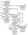
도21은 만재 감지 처리를 도시하는 플로우챠트.Fig. 21 is a flowchart showing full load detection processing.
도22는 만재 감지 처리를 도시하는 플로우챠트.Fig. 22 is a flowchart showing full load detection processing.
<도면의 주요 부분에 대한 부호의 설명><Explanation of symbols for the main parts of the drawings>
A : 화상 형성 장치A: image forming apparatus
B : 배출 처리 장치B: discharge treatment unit
S : 시트S: Sheet
1 : 입구 센서1: inlet sensor
2 : 반송 롤러2: conveying roller
3 : 중간 롤러3: middle roller
4 : 정합 스테이지4: registration stage
5 : 다발 배출 롤러쌍5: bundle ejection roller pair
6 : 정합판6: matching plate
7 : 적재 트레이7: stacking tray
8 : 패들8: paddle
9 : 스탬프9: stamp
10 : 만재 감지 센서 플래그10: full load sensor flag
11 : 다발 배출 대기 위치 센서11: bundle discharge waiting position sensor
13 : 만재 감지 센서13: full load sensor
15 : 스테이플러15: stapler
17 : 스테이플 유무 센서17: Staple presence sensor
18 : 시트 다발 유무 센서18: Sheet bundle presence sensor
19 : 패들 대기 위치 센서19: Paddle Standby Position Sensor
41 : CPU41: CPU
본 발명은 기록 장치에 결합된 배출 처리 장치의 적재량 감지 제어에 관한 것으로서, 특히 시트 배출 모드들에 따른 배출 적재량을 정확하게 감지할 수 있는 배출 처리 장치 및 이러한 배출 처리 장치를 구비하는 화상 형성 장치에 관한 것이다.BACKGROUND OF THE
프린터와 같은 화상 형성 장치들은 각각의 에지가 정합되게 되는 스테이플링 같은 시트 처리시, 복수의 화상 형성(또는 기록) 시트들을 배출하기 위한 배출 처리 장치를 통상적으로 포함한다. 이러한 배출 처리 장치는 화상 형성 장치 본체의 시트 배출구측의 상부면 또는 측면에 형성되고, 이와 같은 타입의 배출 처리 장치로서는 화상 형성 장치 본체 내에서 기록된 시트가 차례로 화상 형성 장치 본체의 배출구로부터 배출 처리 장치로 반송되어 각 에지가 정합되고, 처리시, 시트를 배출하는 것이 알려져 있다.Image forming apparatuses, such as a printer, typically include an ejection processing apparatus for ejecting a plurality of image forming (or recording) sheets during sheet processing such as stapling in which each edge is to be matched. This discharge processing apparatus is formed on the upper surface or the side surface of the sheet discharge port side of the image forming apparatus main body. As this type of discharge processing apparatus, sheets recorded in the image forming apparatus main body are sequentially discharged from the discharge port of the image forming apparatus main body. It is known to convey to an apparatus, to match each edge, and to discharge a sheet at the time of a process.
이러한 배출 처리 장치들은 후처리된 시트 다발들의 적재량을 감지하는 기구를 갖도록 형성되는 경향이 있으며, 제어는 특히 적재부가 가득 차게 되었을 때 종종 배출 처리 장치로 시트 배출을 억제하도록 행하여진다.Such discharge treatment devices tend to have a mechanism for sensing the loading amount of the post-processed sheet bundles, and control is often done to suppress sheet discharge into the discharge treatment device, especially when the load portion becomes full.
그러나, 스테이플 처리와 같은 시트 처리 상태에 있는 시트 다발들이 적재될 때, 스테이플부에서만 적재가 이루어져 적절한 적재가 수행되지 않을 수 있다. 이러한 상태에서, 적재부의 중심에 위치된 적재량 감지 수단은 만재가 감지되지 않을 지라도 만재된 상태로서 감지할 가능성이 있어서, 연속적인 시트들의 반송의 방해를 야기하게 된다.However, when sheet bundles in a sheet processing state such as staple processing are stacked, the stacking may be performed only in the staple portion, so that proper stacking may not be performed. In this state, the load detecting means located at the center of the stacking portion is likely to sense as full loaded even if full load is not detected, causing disturbance of conveyance of continuous sheets.
이러한 문제점을 해결하기 위해서는 중심에서 뿐만 아니라 스테이플링 위치에서도 적재량 감지 수단을 형성할 필요가 있을 수 있다. 하지만, 스테이플링이 시트들의 에지에서 행해질 경우에, 스테이플링 위치는 시트 다발들의 정합 위치 근방인 경향이 있어서 정합 기구 및 적재량 감지 기구의 작동 범위들은 서로 불가피하게 간섭하게 되며, 화상 형성 장치가 적절한 정합 작동 및 적재량의 적절한 감지로 작동하지 않을 수 있다.In order to solve this problem, it may be necessary to form a load sensing means not only at the center but also at the stapling position. However, when stapling is done at the edges of the sheets, the stapling position tends to be near the mating position of the sheet bundles so that the operating ranges of the mating mechanism and the load sensing mechanism inevitably interfere with each other, and the image forming apparatus is properly matched. Proper sensing of operation and payload may not work.
본 발명은 상기 문제점들을 해결하기 위함이다. 본 발명의 목적은 적재된 시트 다발의 적재량을 정확하게 감지할 수 있는 배출 처리 장치와, 이러한 배출 처리 장치를 구비하는 화상 형성 장치를 제공하는 것이다.The present invention is to solve the above problems. SUMMARY OF THE INVENTION An object of the present invention is to provide an emission processing apparatus capable of accurately sensing the stacking amount of stacked sheet bundles, and an image forming apparatus having such an emission processing apparatus.
상기 목적을 달성하기 위한 본 발명에 따른 대표적인 구성은 시트들을 정합하고 소정의 방식으로 시트들을 처리한 후 시트들을 배출하기 위한 배출 처리 장치이며, 정합 스테이지에서는 시트를 정합하고 비정합 기간에는 대기 위치(home position)로 벗어나도록 작동가능한 정합 부재를 구비한 정합 수단과, 정합 스테이지상의 시트를 반송하기 위한 반송 수단과, 정합 스테이지상의 시트에 소정의 처리를 수행하기 위한 시트 처리 수단과, 배출부로 배출된 시트의 적재량을 감지하도록 정합 부재의 작동 영역과 겹치는 영역에서 감지 위치와 비감지 위치로 선택적으로 이동하는 감지 부재를 구비한 적재량 감지 수단을 구비하고, 적재량 감지 수단은 시트 처리 수단에 의해 처리된 시트들이 배출부로 배출되는 제1 배출 모드동안 배출부에 적재된 시트들의 적재량을 감지하기 위한 제1 적재량 감지 모드와, 정합 작동을 수행하지 않고 배출부로 시트를 배출하기 위한 제2 배출 모드동안 배출부에 적재된 시트들의 적재량을 감지하기 위한 제2 적재량 감지 모드를 구비한다.A representative configuration according to the present invention for achieving the above object is a discharge processing apparatus for discharging the sheets after mating the sheets and processing the sheets in a predetermined manner, and in the mating stage, the sheets are matched and the standby position ( registration means having a mating member operable to deviate to a home position, conveying means for conveying the sheet on the mating stage, sheet processing means for performing a predetermined process on the sheet on the mating stage, and discharged to the discharge unit. And a load sensing means having a sensing member for selectively moving to a sensing position and a non-sensing position in an area overlapping with the operating area of the mating member to sense the stacking amount of the sheet, wherein the stacking sensing means is a sheet processed by the sheet processing means Of the sheets loaded in the discharge section during the first discharge mode in which A first load detection mode for detecting a discretion, and a second load detection mode for detecting a load of sheets loaded in the discharge unit during the second discharge mode for discharging the sheet to the discharge unit without performing a matching operation; .
본 발명에 따르면, 시트들을 정합하기 위한 정합 부재 및 시트들의 적재량을 감지하기 위한 감지 부재의 작동가능한 범위들이 서로 겹치는 배출 처리 장치에서도 시트들이 처리되는 경우 및 시트들이 처리되지 않는 경우에 감지 모드를 변화시킴으로써 시트 적재량이 정확하게 감지될 수 있다.According to the present invention, the sensing mode is changed when the sheets are processed and when the sheets are not processed even in the discharge processing apparatus in which the operable ranges of the mating member for mating the sheets and the sensing member for sensing the loading amount of the sheets overlap each other. By doing so, sheet loading can be accurately detected.
다음으로, 본 발명의 실시예에 따른 배출 처리 장치에 있어서, 배출 처리 장치를 구비하는 화상 형성 장치에 대한 일례로서 레이저 비임 프린터가 설명된다.Next, in the discharge processing apparatus according to the embodiment of the present invention, a laser beam printer will be described as an example of the image forming apparatus provided with the discharge processing apparatus.
[제1 실시예][First Embodiment]
도1은 배출 처리 장치를 구비하는 화상 형성 장치를 도시하는 단면이다. 도2는 본 발명에 따른 배출 처리 장치의 반송로의 단면을 도시하는 설명도이다. 도3은 정합 처리부를 도시하는 평면 설명도이다. 도4는 배출구의 방향에서 볼 때 정합 처리부를 도시하는 단면 설명도이다. 도5는 전기 블록도이다. 1 is a cross-sectional view showing an image forming apparatus having an ejection processing apparatus. 2 is an explanatory view showing a cross section of a conveyance path of the discharge treatment apparatus according to the present invention. 3 is a plan explanatory view showing a matching processing unit. 4 is a cross-sectional explanatory view showing a matching processing unit as viewed from the direction of the discharge port. 5 is an electrical block diagram.
{배출 처리 장치를 구비하는 화상 형성 장치의 일반적인 구성}{General structure of an image forming apparatus having an emission processing apparatus}
먼저, 도1을 참조하여 화상 형성 장치(A) 및 배출 처리 장치(B)의 개략 구성이 설명된다. 화상 형성 장치(A)는 컴퓨터 또는 LAN과 같은 네트워크에 단독 접속되고, 컴퓨터 또는 네트워크로부터 전달된 화상 정보 또는 프린터 신호등에 기초한 소정의 화상 형성 처리를 통해 시트에 화상을 형성(또는 기록)하고 시트를 배출하는 장치이다.First, with reference to FIG. 1, the schematic structure of the image forming apparatus A and the discharge processing apparatus B is demonstrated. The image forming apparatus A is solely connected to a network such as a computer or a LAN, and forms (or records) an image on a sheet through a predetermined image forming process based on image information or a printer signal transmitted from the computer or network, and forms the sheet. It is a device to discharge.
화상 형성 장치(A)에 있어서는, 복수의 시트(S)들이 공급 카세트(110)에 적재되고, 다양한 롤러들이 적재된 시트에서 한시트씩 최상단 시트를 분리 공급한다. 컴퓨터 또는 네트워크로부터 공급된 소정의 프린터 신호에 따라, 토너 화상들이 화상 형성 장치(A)의 공급 카세트(110)으로부터 공급된 시트(S)에 소위 레이저 비임 방법의 화상 형성 처리로 형성되는 화상 형성부(111)에서 토너 화상들이 시트의 상부면에 전사되고, 이후에 토너 화상은 하류측에 위치된 정착 유닛(112)에서 열 및 압력을 인가함으로써 정착된다.In the image forming apparatus A, the plurality of sheets S are stacked in the
화상이 정착되는 시트(S)는 화상면을 반전시키도록 배출 롤러(113)로 연장되는 실질적으로 U형의 시트 반송로에서 바뀌고, 배출 롤러(113)에 의해 화상 형성 장치(A)의 상부에 형성된 페이스 다운 배출 트레이(114)로 화상 측면이 하측으로 배출된다. 시트(S)는 도시되지 않은 제어기로부터의 제어 신호에 기초하여 화상 형성 장치(A)의 플래퍼(115)의 위치 선택에 의해 페이스 다운 배출 트레이(114) 또는 배출 처리 장치(B)로 선택적으로 배출된다.The sheet S on which the image is fixed is changed in a substantially U-shaped sheet conveying path extending to the
복수의 시트들이 시트 다발을 형성하도록 정합되는 화상 형성 장치(A)에서 화상들이 기록되고 배출되는 시트들에 대한 시트 처리 수단에서 스테이플링 또는 펀칭과 같은 소정의 처리를 수행하기 위해, 배출 처리 장치(B)는 화상 형성 장치(A)의 상부에 배치된다. 배출 처리 장치(B)는 시트 처리를 수행하지 않고 단순히 배출 및 적재를 행하는 기능을 또한 가질 수 있다. 본 실시예에 따른 배출 처리 장치(B)가 시트 처리 수단으로서 스테이플링 처리를 수행하는 스테이플링 기능을 구비하는 것은 주목할 만하다.In order to perform a predetermined process such as stapling or punching in the sheet processing means for the sheets from which images are recorded and ejected in the image forming apparatus A in which a plurality of sheets are matched to form a sheet bundle, an ejection processing apparatus ( B) is disposed above the image forming apparatus A. FIG. The discharge processing apparatus B may also have a function of simply discharging and stacking without performing sheet processing. It is noteworthy that the discharge processing apparatus B according to the present embodiment has a stapling function of performing stapling processing as sheet processing means.
배출 처리 장치(B)와 화상 형성 장치(A)는 도시되지 않은 케이블 커넥터로 서로 전기 접속되고, 배출 처리 장치(B)는 화상 형성 장치(A)에 착탈가능하게 부착된다.The discharge processing apparatus B and the image forming apparatus A are electrically connected to each other by a cable connector (not shown), and the discharge processing apparatus B is detachably attached to the image forming apparatus A. FIG.
{배출 처리 장치}{Ejection processing unit}
도2를 참조하여 배출 처리 장치(B)의 구성이 설명된다. 도2a에 도시된 바와 같이, 화상 형성 장치(A)로부터 공급된 시트는 입구 센서(1)에 의해 감지되고, 반송 롤러(2)에 의해 반송되며 반송 수단으로서의 중간 롤러(3)에 의해 정합 스테이지(4)로 반송된다. 시트는 선택적으로, 다발 배출 수단으로서의 다발 배출 롤러쌍(5;5L, 5U)과 분리 및 닙핑되고, 소정의 처리가 행해진 후 적재 트레이(7)로 배출된다.With reference to FIG. 2, the structure of the discharge processing apparatus B is demonstrated. As shown in Fig. 2A, the sheet fed from the image forming apparatus A is sensed by the
반송 롤러(2), 중간 롤러(3), 다발 배출 하부 롤러(5L) 및 다발 배출 상부 롤러(5U)의 회전은 반송 모터(M1)에 의해 구동된다. 다발 배출 롤러쌍(5)의 닙핑 및 분리 위치들은 분리 모터(M3)에 의해 구동된 캠에 의해 결정된다. 캠은 위치 센서 플래그에 결합되고, 플래그가 포토 센서로서의 다발 배출 롤러 대기 위치 센서(11)를 차광한 위치가 분리 위치이고, 투광하는 위치가 닙핑 위치가 된다.Rotation of the conveying
도면 부호 6은 측방향으로 시트 다발을 정합하기 위한 정합 수단의 정합 부재로서의 정합판이고, 정합 모터(M4; 스태핑 모터)로 위치 결정된다. 정합판(6)은 도3에 도시된 바와 같이, 시트 좌측 에지를 미는 좌측 정합판(6L) 및 시트 우측 에지를 미는 우측 정합판(6R)으로 구성되고, 벗어난 위치(A, escaping position), 대기 위치(B), 정합 위치(C) 및 느슨한 정합 위치(D)들 중 하나로 이동한다. 정합판 대기 위치 센서(12)는 벗어난 위치를 감지하도록 벗어난 위치(A)에 배치된다. 우측 정합판(6R)은 판(6R)이 대기 위치(B)로부터 내향으로 이동하지 않게 하는 기구를 구비하여서, 정합 작동은 시트 크기에 따라서만 좌측 정합판(6L)으로 행하여진다.
도면 부호 7은 적재 트레이(7)이다. 도면 부호 8은 정합 스테이지(4)로부터 돌출된 시트를 후방으로 잡아당기기 위한 패들이고, 패들 모터(M2)에 의해 시계방향으로 회전한다. 패들 기구는 패들 모터(M2)의 회전 제어로 사용되는 패들 대기 위치 센서(19)를 구비한다.
도면 부호 9는 정합된 시트 다발들을 가압하기 위한 스탬프이고, 플런저 타입의 솔레노이드(SL)로 격리되고 가압된다. 솔레노이드(SL)가 작동될 때, 스탬프는 격리되며, 반면에 솔레노이드(SL)가 작동되지 않을 때, 스탬프는 가압하도록 하향 이동된다.
도면 부호 10은 만재 감지 센서 플래그이고 대향 단부(10a, 10b)들이 절첩되는 판형인 구조를 구비하며, 적재 감지 플래그(10)는 상류 측면의 일단부에 위치된 피봇축(10c)의 형성으로 피봇식으로 이동한다. 만재 감지 센서 플래그(10)는 다발 배출 상부 롤러(5U) 상에 위치되고, 다발 배출 롤러쌍(5)이 닙핑상태에 있는 동안 적재 트레이(7) 상의 시트들이 만재 레벨에 도달할 때, 만재 감지 센서(13)를 차단함으로써 만재 상태를 감지하는 적재량 감지 수단에 대한 감지 부재로서 작동을 한다. 만재 감지 센서 플래그(10)는 다발 배출 롤러쌍(5)이 격리되어 있는 도2a에 도시된 바와 같이, 구동 장치에 의해 상방으로 벗어나는 구조를 구비하고, 이에 따라서 만재 감지가 억제되는 비감지 상태로 들어간다. 도4에 도시된 바와 같이, 만재 감지 센서 플래그(10)는 스테이플 위치에서 시트 다발의 증대를 정확하게 감지하도록 시트의 중심뿐만 아니라 대향 단부에서도 배치된다. 따라서, 정합판(6) 및 만재 감지 센서 플래그(10)의 작동 범위들이 서로 간섭하거나 또는 중첩하는 것으로 판단된다.
도2b에 도시된 바와 같이, 정합 작동이 종료되고, 정합판(6)이 대기 위치로 복귀하며 다발 배출 롤러쌍(5)이 닙핑하게 되는 위치에서, 만재 감지 센서 플래그(10)는 적재 트레이(7)의 측면에 피봇식 이동하고, 일단부(10a)는 적재 트레이(7)에 적재된 시트 다발과 접촉하게 되어서, 소정의 시트 다발의 적재량이 감지되게 된다는 것은 주목할만하다.As shown in Fig. 2B, at the position where the mating operation ends, the
도면 부호 15는 스테이플러이고, 스테이플 모터(M5)의 구동에 의해 정합 스테이지(4)에 정합된 시트 다발의 좌측 후방부에서 경사진 방식으로 스테이플한다. 스테이플러(15)는 스테이플러의 초기 위치를 지시하는 스테이플러 대기 위치 센서(16)와 비스테이플링 작동의 예정을 감지하는 스테이플 유무 센서(17)를 포함한다.
도면 부호 18은 정합 스테이지(4) 상의 시트 다발 유무 센서이고, 스테이플링 후 다발 배출 및 적재 작동이 적절하게 행하여지는지에 대한 판단하도록 사용된다.
{제어 구성}{Control configuration}
도5의 CPU(41)는 롬(ROM)들과 램(RAM)들을 내장하는 하나의 칩 마이크로프로세서이고, 각각의 구동 회로들로의 구동 신호들을 출력하며 각각의 센서 입력 회로로부터의 센서 신호들을 입력한다. CPU(41)는 도시되지 않은 프린터 제어기와 시리얼 통신을 통해 제어 정보 및 상태 정보를 또한 송수신한다. The
이하, 배출 처리 장치(B)의 각각의 기구들을 사용하면서, 전원 ON시의 초기화 처리, 시트 반송 관리 처리, 시트 다발의 처리 및 에러 감지와 에러 처리에 대하여 CPU(41)가 제어하는 방법이 플로우챠트를 참조하여 설명된다.Hereinafter, the method which the
(1) 초기화 처리(1) initialization
도6은 장치의 초기화 처리를 도시하는 플로우챠트이다. 전원이 투입될 때, CPU(41)는 스텝(501)에서 도시되지 않은 프린터 제어기와의 통신을 개통시킨다. 통신들을 개통하면, 프린터 제어기 및 CPU(41)는 스텝(502)에서 서로의 장치 정보를 송수신한다.6 is a flowchart showing the initialization process of the apparatus. When the power is turned on, the
스텝(503)에서, 초기화 가능 상태가 프린터 제어기에 통지되고, CPU는 스텝(504)에서 프린터 제어기로부터의 초기화 지시를 대기한다. 배출 처리 장치를 포함하는 프린터 시스템에서의 초기화 처리는 프린터에서의 잔류 시트들의 감지 및 배출을 포함하므로, 초기화가 배출 처리 장치(B)에서만 행해진다면 잔류 시트들은 손상을 받을 수 있다. 따라서, 프린터 제어기는 도시되지 않은 프린터 엔진 제어기와 통신하고, 시스템의 모든 장치가 초기화될 수 있는 시스템의 모든 장치에 초기화 지시를 전송한다.In
프린터 제어기로부터의 초기화 지시를 수신하면, 스테이플러(15)는 스텝(505)에서 초기화되고, 이후에 스텝(506)에서 장치에 잔류하는 시트 감지 처리, 스텝(507)에서 정합판(6)의 초기화 처리, 스텝(508)에서 패들 기구(8)의 초기화 처리, 스텝(509)에서 다발 배출 롤러쌍(5)의 초기화 처리 및 스텝(510)에서 정합 스테이지(4) 상에 잔류하는 시트의 배출 처리가 수행된다.Upon receiving the initialization instruction from the printer controller, the
이러한 배출 처리 루틴은 다음의 사항들에 유의하여 구성된다.This discharge treatment routine is structured with attention to the following points.
(i) 정합판(6)의 초기화 처리는 다발 배출 롤러쌍(5)의 초기화 처리 전에 행해진다. 그 이유는 다발 배출 롤러쌍(5)이 닙핑 상태에 있고 정합판(6)이 벗어난 위치에 있을 때, 사용자가 실수로 중심 방향을 향하여 정합판(6)을 밀었다면 만재 감지 센서 플래그(10)는 정합판(6)의 아래에 위치되도록 하는 위치 관계를 가진다. 다발 배출 롤러쌍(5)의 초기화 처리가 이러한 상황하에서 스텝(509)에서 처음으로 행해지면, 만재 감지 센서 플래그(10)와 정합판(6)은 서로 간섭하게 되어 파손이 일어나게 된다. 따라서, 정합판(6)의 초기화 처리는 다발 배출 롤러쌍(5)의 초기화 처리 전에 행해져야 한다.(i) The initialization process of the
(ii) 다른 고려 사항은 장치에 잔류하는 시트들의 감지 전에 스테이플러(15)의 초기화를 실행하는 것이다. 그 이유는 다음과 같다. 스테이플러(15)는 스테이플러가 시트 다발과 결합될 때 또는 소위 스테이플 잼 상태일 때 초기화 처리 상태에 있게 될 수 있다. 그 때, 시트 잼으로 판단되는 장치에 잔류하는 시트들의 감지시 연속적인 초기화 처리들이 정지되는 시트 다발과 결합되는 상태로 스테이플러(15)가 남아있기 때문에 시트 다발을 제거한 경우에서 조차도 사용자가 스테이플을 제거할 수 없는 문제가 발생할 수 있다. 따라서, 스테이플러(15)가 초기화된 후, 장치에 잔류하는 시트의 처리가 행해져야 한다.(ii) Another consideration is to carry out the initialization of the
다음으로, 각각의 초기화의 처리 스텝이 플로우챠트에 따라 설명된다. 도7은 스테이플러의 초기화 처리를 도시하는 플로우챠트이다.Next, the processing steps of each initialization are explained according to the flowchart. 7 is a flowchart showing an initialization process of a stapler.
스텝(601)에서, 제어용 타이머가 개시된다. 스텝(602)에서, 스테이플러(15)의 스테이플러 대기 위치 센서(16)는 스테이플러(15)가 초기 상태에 있는지[또는 스테이플러(15)가 대기 위치에 위치되는지]에 대해 판단되도록 확인된다. 스테이플러가 초기화 상태에 있지 않으면, 스테이플러 복구 처리가 스텝(603)에서 행해진다. 스테이플러 복구 처리는 스테이플링을 하는 역방향으로 소정의 시간동안 스테이플러 모터(M5)를 회전시킴으로써 수행된다. 스텝(604, 605)에서, 스테이플러(15)의 스테이플러(15)가 초기 상태로 복귀되는 것을 발견하도록 스테이플러 대기 위치 센서(16)가 소정의 시간동안 확인된다. 스테이플러(15)가 대기 위치에 위치되어 있는 것으로 감지되지 않으면, 스테이플러 모터(M5)는 스텝(606)에서 정지되고, 작동은 스텝(607)에서 소정 시간동안 정지된다. 스테이플러 모터(M5)는 스텝(604, 605)에서와 동일한 방식으로 스텝(609, 610)에서 다시 스테이플러 복구 처리를 수행하도록 스텝(608)에서 다시 역방향으로 작동된다. 스테이플러 대기 위치가 스텝(609)에서 여전히 확인되지 않을 때, 스텝(611)에서 스테이플러 기능 불량 처리가 실행된다. 스테이플러 대기 위치가 스텝(602, 604, 609)에서 감지되면, 스테이플러(15)의 초기화 처리가 종료되고, 스테이플 모터(M5)는 스텝(612)에서 정지된다. 스텝(611)에서의 스테이플러 기능 불량 처리에서, 스테이플러의 기능 불량은 도시되지 않은 프린터 제어기에 통지되고, 모든 초기화 처리가 중지된다.In
도8은 장치에 잔류하는 시트들의 감지 처리 및 정합판 초기화 처리를 도시하는 플로우챠트이다. 스텝(700)에서, 제어용 타이머가 개시된다. 스텝(701)에서, 시트가 배출 처리 장치(B)에 잔류하는지를 판단하도록 입구 센서(1)가 확인된다. 시트가 잔류하면, 장치에 잔류하는 시트에 대한 잼 처리가 스텝(702)에서 수행된다. 잼 처리는 도시되지 않은 프린터 제어기에 잼을 통지하고 연속적인 초기화 처리들을 중지하도록 하는 것이다. 잔류하는 시트가 감지되지 않으면, 정합판에 대한 초기화 처리가 수행된다.Fig. 8 is a flowchart showing the sensing process and the registration plate initialization process of the sheets remaining in the apparatus. In
먼저, 정합판 대기 위치 센서(12)가 스텝(703)에서 정합판(6)을 감지하는 지에 대해 확인된다. 감지되지 않으면, 작동은 스텝(709)에서의 처리로 이동된다. 감지되면, 정합 모터(M4)는 스텝(704)에서 정상 방향으로 회전하도록 구동되고, 스텝(705)에서 정합판 대기 위치 센서(12)가 정합판(6)을 감지하지 않게 되는지에 대해 확인된다. 여기에서, 모터(M4)의 구동 시간이 측정되고, 스텝(706)에서의 소정의 시간보다 더 구동되었다고 판단되면 스텝(720)에서의 기능 불량 처리는 정합 모터(M4)가 기능 불량이라고 판단될 때 수행된다. 기능 불량 처리에서, 정합 모터의 기능 불량은 도시되지 않은 프린터 제어기에 통지되고, 연속적인 초기화 처리들은 수행되지 않는다. 소정의 시간 내에 있으면, 작동은 스텝(705)으로 복귀된다. 정합판 대기 위치 센서(12)가 스텝(705)에서 정합판(6)을 감지하지 않게 되면, 정합 모터(M4)는 스텝(707)에서 소정량만큼 정상적인 방향으로 추가로 구동된다. 모터의 회전 방향을 절환하도록 소정 시간동안 정지 처리 스텝(708, 709)를 통과한 후, 정합 모터(M4)는 스텝(710)에서 역방향으로 구동되고, 정합판 대기 위치 센서(12)가 스텝(711)에서 정합판(6)을 감지하였는지에 대해 확인된다. 여기에서, 모터(M4)의 구동 시간이 또한 측정되고, 스텝(712)에서 소정 시간보다 더 구동되었다고 판단되면, 정합 모터(M4)가 기능 불량인 것으로 판단될 때 스텝(720)에서 기능 불량 처리가 수행된다. 소정의 시간에 아직 도달하지 않았으면, 작동은 스텝(711)에서의 처리로 복귀된다.First, it is checked whether the matching plate
정합판 대기 위치 센서(12)가 스텝(711)에서 정합판(6)을 감지한 경우, 정합 모터(M4)는 스텝(713)에서 소정량만큼 역방향으로 구동되고, 모터는 스텝(714)에서 정지된다. 이것으로 정합판의 초기화 처리의 종료이다.When the matched plate
도9는 패들 기구의 초기화 처리를 도시하는 플로우챠트이다.9 is a flowchart showing initialization processing of the paddle mechanism.
먼저, 제어용 타이머가 스텝(800)에서 개시된다. 패들 모터(M2)는 스텝(801)에서 정상적인 방향으로 구동되고, 패들 대기 위치 센서(19)가 스텝(801)에서 패들과 함께 회전하지 않는 도시되지 않은 패들 센서 플래그를 감지하였는지에 대해 확인된다. 감지되지 않으면, 작동은 스텝(807)에서의 처리로 복귀된다. 감지되었다면, 스텝(803, 804)에서 패들 대기 위치 센서(19)가 소정 시간동안 패들 센서 플래그를 감지하였는지에 대해 확인된다. 소정 시간 이상으로 구동되었을 지라도 센서가 여전히 패들 센서 플래그를 감지하면, 패들 모터(M2)의 기능 불량으로 판단되고, 스텝(810)에서 기능 불량 처리가 수행된다. 기능 불량 처리에서, 패들 모터의 기능 불량은 도시되지 않은 프린터 제어기로 통지되고, 연속적인 초기화 처리들이 정지된다.First, a control timer is started at
스텝(803)에서, 패들 대기 위치 센서(19)가 패들 센서 플래그를 감지하지 않게 되면, 패들 모터(M2)는 원래의 정상적인 방향으로 추가로 구동되고, 스텝(807, 808)에서, 소정의 시간내에 패들 대기 위치 센서(19)가 패들 센서 플래그를 감지하였는지에 대해 확인된다. 스텝(808)에서, 소정의 시간 이상동안 구동되었다고 판단되면, 스텝(810)에서 기능 불량 처리를 수행하도록 패들 모터(M2)의 기능 불량으로 판단된다. 패들 대기 위치 센서(19)가 스텝(807)에서 패들 센서 플래그를 감지하면, 패들 모터(m2)는 스텝(809)에서 정지되고, 이에 따라 패들 기구의 초기화 처리를 종료하게 된다.In
도10은 초기화 처리 및 다발 배출 롤러의 다발 배출 처리를 도시하는 플로우 챠트이다.10 is a flowchart showing the initialization processing and the bundle discharge processing of the bundle discharge roller.
먼저, 제어용 타이머가 스텝(901)에서 개시된다. 이격 모터(M3)는 스텝(902)에서 정상적인 방향으로 구동되고, 다발 배출 대기 위치 센서(11)가 다발 배출 롤러용 위치설정 캠과 함께 회전하는 도시되지 않은 위치 센서 플래그를 감지하는 스텝(903)에서 확인된다. 감지되지 않으면, 작동은 스텝(907)에서의 처리로 이동된다.First, a control timer is started at
감지되면, 다발 배출 대기 위치 센서(11)가 위치 센서 플래그를 감지하지 않게 되는 것은 스텝(903, 904)에서 확인된다. 모터가 스텝(904)에서 소정의 시간이상동안 구동되었다고 판단되면, 스텝(905)에서 기능 불량 처리를 수행하도록 이격 모터(M3)의 기능 불량으로 판단된다. 기능 불량 처리에서, 이격 모터의 기능 불량은 도시되지 않은 프린터 제어기에 통지되고, 연속적인 초기화 처리들은 중지된다. 다발 배출 대기 위치 센서(11)가 스텝(903)에서 위치 센서 플래그를 감지하지 않게 될 때, 이격 모터(M3)는 정상적인 방향으로 추가로 구동되고, 소정의 시간내에서 패들 대기 위치 센서(19)가 패들 센서 플래그를 감지하는 것은 스텝(907, 908)에서 확인된다. 소정 시간 이상동안 스텝(908)에서 구동된 것으로 판단되면, 스텝(915)에서 기능 불량 처리를 하도록 이격 모터(M3)의 기능 불량으로 판단된다. 다발 배출 롤러 대기 위치 센서(11)가 스텝(907)에서 위치 센서 플래그를 감지하면, 다발 배출 롤러 대기 위치 센서(11)가 위치 센서 플래그를 감지하지 않게 될 때까지 스텝(909)에서의 처리를 반복하도록 계속 회전된다. 센서가 플래그를 감지하지 않게 될 때, 이격 모터(M3)는 스텝(910)에서 정지되고, 이에 따라 다발 배출 롤러의 초기화 처리를 종료하게 된다. 즉, 다발 배출 롤러쌍(5)은 닙핑 상태에서 초기화 처리를 종료하게 된다.If detected, it is confirmed in
반송 모터(M1)는 스텝(911)에서 구동된다. 구동 시간은 또한 여기에서도 측정되고, 모터가 소정 시간동안 구동되는 것이 스텝(912)에서 확인된다. 다발 배출롤러쌍(5)이 닙핑 상태에 있고 정합판(6)은 벗어난 위치에 있기 때문에, 시트 또는 시트들이 정합 스테이지(4) 상에 잔류하면 이러한 처리는 시트 다발이 적재 트레이로 배출되게 한다. 따라서, 다발 배출 센서(18)는 스텝(913)에서 확인 상태에 있게 되고, 시트가 존재하면 장치에 잔류하는 시트들에 대한 잼 처리가 스텝(914)에서 수행된다. 시트가 존재하지 않으면, 모든 초기화 처리들은 여기에서 종료된다. The conveying motor M1 is driven in
스탬프 기구는 특히 솔레노이드(SL)가 CPU(41)의 포트 세팅에서 꺼지고 꺼질 때 스탬프가 하방으로 가압되기 때문에 초기화 처리가 요구되지 않는다.The stamp mechanism does not require initialization processing, especially because the stamp is pressed downward when the solenoid SL is turned off and off at the port setting of the
(ⅱ) 시트 반송 관리 처리(Ii) sheet return management processing
작업(job) 정보 및 반입되는 시트의 페이지 정보는 시트가 프린터로부터 반입되기 전 통신을 통해 도시되지 않은 프린터 제어기로부터 CPU(41)로 보내진다. 작업 정보는 작업에서 행해지는 시트 처리 정보가 추가된다. 본 실시예에 따른 배출 처리 장치(B)는 스테이플링 기능과 시트 처리없는 단순 적재 기능을 구비하고 하나를 선택한 지정이 작업 정보로서 프린터 제어기로부터 전송된다. 페이지 정보는 페이지 ID, 디스크립터(descriptor) 및 시트 크기로 구성된다. 페이지 ID는 각각의 페이지에 할당된 개개 수이다. 디스크립터는 작업에서 시트의 위치 상태를 나타내는 정보이고, 작업의 제1 페이지는 SOJ(작업의 시작)로 할당되지만 작업의 최종 페이지는 EOJ(작업의 끝)으로 할당된다.Job information and page information of the sheet to be loaded are sent to the
프린트 제어기로부터 작업 정보 및 페이지 정보를 수용하는 CPU(41)는 정보를 저장하고 프린터 제어기에 필요한 시트 간격 시간을 전송한다. 이것은 일반적으로 영초이지만, 스테이플링 처리 등의 경우에 소정의 스테이플 작동 시간은 보증되어야 한다. 필요한 시트 간격 시간을 수용하는 프린터 제어기는 지정 시간만큼 상응하는 페이지로 프린트 시작을 연기하므로, 시트 간격을 보증한다. 다음, CPU(41)는 프린터 제어기로부터 스케쥴 지시를 반입하도록 대기한다. 반입 스케쥴 지시는 배출 처리 장치(B)에서 시트가 반입되기 바로 전에 내려진다. 반입 스케쥴 지시를 수용하는 CPU(41)는 시트 배출 처리를 실행한다.
도11은 시트 반송 관리 처리를 도시한 플로우챠트이다. 이러한 처리는 소정의 짧은 반복 기간으로 실행된다. 스텝(1001)에서, 작업 정보가 수신되는 지에 대해 판단되고 만약 작업 정보가 수신되면 그 정보는 스텝(1002)에 저장된다. 페이지 정보가 수신되는 지에 대해 판단되고, 만약 페이지 정보가 수신되면 스텝(1004)에서 수신된 페이지 정보는 반송 관리 테이블에 추가적으로 등록된다. 반송 관리 테이블은 4 페이지의 페이지 정보를 등록할 수 있는 링크 버퍼이다. 반송 관리 테이블의 페이지 정보는 스텝(1001)에 저장된 1비트의 작업 정보 및 도12에 도시된 바와 같이 프린터 제어기로부터 수신된 페이지 정보에 추가적으로 반송 상태를 나타내는 2 비트의 반송 정보를 포함한다. 만약 반송 정보가 "00B"면, 단지 페이지 정보를 수신하고 반입 스케쥴 정보를 수신하지 않는 상태를 나타내고, 만약 반송 정보가 "01B"면, 시트 반송 작업이 진행되는 상태를 나타내고, 만약 반송 정보가 "10B"면, 반송 종료를 나타내고, 만약 반송 정보가 "11B"면, 반송 중에 하나의 오류 또는 오류들의 발생을 나타낸다.Fig. 11 is a flowchart showing the sheet conveyance management process. This process is executed with a predetermined short repetition period. In
스텝(1005)에서, 반입 스케쥴 정보가 수신되는지에 대해 판단된다. 만약 수신되면, 가장 오래된 시간에 등록된 반송 정보는 스텝(1006)에서 조사되고 반송 정보는 "01B"로 할당된다. 스텝(1007)에서, 페이지 정보의 작업 정보가 확인되고, 만약 그것이 단순 적재 작업이면, 단순 적재 반송 처리 태스크(task)는 스텝(1008)에서 시작되지만 만약 그것이 스테이플링 작업이면 스테이플링 반송 처리 태스크는 스텝(1009)에서 시작된다. 이러한 태스크를 위해, 페이지 정보의 어드레스가 주어지고, 그 각각의 태스크는 또한 페이지 정보를 기초로 반송 처리를 수행한다.In
"스테이플링 반송 처리"는 시트 처리 수단으로 스테이플링 기능에 의해 스테이플링 처리가 행해지는 시트 다발을 반송부로서 적재 트레이(7)로 배출하기 위한 스테이플 배출 모드(제1 배출 모드)를 의미하고, "단순 적재 반송 처리"는 정합 작업을 실행하지 않고 시트를 적재 트레이(7)로 배출하기 위한 단순 배출 모드(제2 배출 모드)를 의미한다.Means a staple discharge mode (first discharge mode) for discharging a sheet bundle in which the stapling process is performed by the stapling function by the sheet processing means to the stacking
반송 관리 테이블은 스텝(1010)에서 조사되고, "10B"의 데이터를 갖는 반송 정보가 선택된다. "10B"의 반송 정보를 갖는 페이지 정보가 발견될 때 반송 단부뿐 아니라 페이지 ID는 스텝(1011)에서 프린터 제어기로 통지된다. 페이지 정보의 디스크립터는 스텝(1012)에서 확인되고, 만약 EOJ가 추가되면 작업의 끝이 스텝(1013)에서 프린터 제어기에 통지된다. 다음에, 페이지 정보는 스텝(1014)에서 반송 관리 테이블로부터 삭제된다. 만약, "10B"를 갖는 어떤 반송 정보도 스텝(1010)에 존재하지 않으면, 그 작업은 스텝(1015)에서 후속 공정으로 이동한다.The conveyance management table is examined at
반송 관리 테이블은 스텝(1015)에서 조사되고, "11B"의 데이터를 갖는 반송 정보가 선택된다. "11B"데이터의 반송 정보가 반송 오차 발생을 지시하기 때문에, 반송 정지 처리가 스텝(1016)에서 행해진다. 반송 정지 처리에서, 모든 반송 태스크의 정지 및 삭제, 모터와 같은 모든 구동 시스템의 정지, 오차 정보와 관련된 프린터 제어기로의 통지 및 반송 정보의 삭제가 실행된다.The conveyance management table is checked in
(ⅲ) 단순 적재 반송 공정(Iii) simple loading and conveying process
도13은 단순 적재 처리를 도시하는 플로우챠트이다. 후술되는 이러한 처리 및 스테이플링 반송 처리는 각각의 시트에 행해진 태스크 처리이고, 일 시트의 반송이 제어되면서 다른 시트가 반입될 때 사실상 동일한 처리 태스크가 시작되고 그 처리가 이전 페이지에 대한 반송 처리와 병렬식으로 행해지는 프로그램 구조를 구비한다.13 is a flowchart showing a simple loading process. These processing and stapling conveyance processing described below are task processing performed on each sheet, and the same processing task is started when another sheet is imported while the conveyance of one sheet is controlled, and the processing is parallel with the conveying processing for the previous page. It has a program structure that is performed in an manner.
먼저, 타이머는 스텝(1201)에서 시작된다. 다음에, 반송 모터(M1)에 대한 구동 시작 지시는 스텝(1202)에서 반송 모터 구동 처리로 주어진다. 입구 센서(1)는 시트가 배출 처리 장치(B)에 반입되는 지를 찾도록 스텝(1203)에서 확인한다. 만약 시트가 반입되지 않으면, 타이머 수치는 스텝(1204)에서 확인하고, 만약 그것이 소정의 시간 이상을 지나면 그것은 지연된 잼(jamming)으로 판단되어 스텝(1215)에서 잼 처리를 실행한다. 만약 그것이 소정의 시간 내면, 그 작업은 스텝(1203)에서 그 처리로 복귀한다.First, the timer is started at
시트가 스텝(1203)에서 감지되는 경우 입구 센서(1)는 시트의 후방 단부를 발견하도록 스텝(1205)에서 확인한다. 만약 후방 단부가 발견되지 않으면, 타이머 수치는 스텝(1206)에서 확인되고, 만약 그것이 각각의 시트 크기 이상에 대해 소정의 시간 설정을 지나면 그것은 스텝(1215)에서 잼 처리를 실행하도록 잔류 잼으로 판단한다. 만약 소정의 시간 내면, 그 작업은 스텝(1205)에서 그 처리로 복귀한다.If the sheet is detected at
시트의 후방 단부가 스텝(1205)에서 감지되는 경우에 타이머 카운터는 그 수치를 새롭게 계산하도록 스텝(1207)에서 재설정된다. 입구 센서(1)로부터 다발 배출 센서(18)까지의 반송 거리가 최소 시트 크기보다 짧기 때문에 다발 배출 센서(18)는 시트의 후방 단부를 발견하도록 스텝(1208)에서 확인한다. 만약 시트의 어떤 후방 단부도 발견되지 않으면 타이머 수치는 스텝(1209)에서 확인되고 스텝(1215)에서 잼 처리를 실행하도록 잔류 잼으로서 판단된다. 만약 이것이 소정의 시간 내면 그 작업은 스텝(1208)에서 그 처리로 복귀한다.If the rear end of the sheet is detected at
만약 시트의 후방 단부가 스텝(1208)에서 감지되면 반송 모터(M1)의 정지 지시는 스텝(1210)에서 반송 모터 구동 처리로 주어진다. 도시되지 않는 반송 모터 구동 처리는 온오프식 카운터를 구비하고, 구동 시작 지시가 주어질 때 온오프식 카운터는 1 증가분만큼 증가되는 반면 구동 정지 지시가 주어질 때 온오프식 카운터는 1 증가분만큼 감소된다. 온오프식 카운터가 "0"에서 "1"까지 변화될 때 반송 모터(M1)는 구동을 시작하는 반면, 온오프식 카운터가 "1"에서 "0"까지 변화될 때 반송 모터(M1)는 정지한다. 다른 카운터 수치에서, 반송 모터의 상태는 유지된다. 이러한 조절로 정확한 반송 처리는 복수의 반송 처리 태스크가 구동 지시 및 정지 지시를 주는 경우에도 행해질 수 있다. "10B" 데이터는 스텝(1211)에서 반송 관리 처리에 주어진 페이지 정보의 반송 정보로 설정되므로 반송 처리를 마감한다.If the rear end of the seat is detected at
스텝(1215)의 잼 처리에서, "11B" 데이터는 주어진 페이지 정보의 반송 정보로 설정되므로 도시되지 않은 오차 정보 영역에 각각의 잼 형태를 설정하고 반송 처리를 마감한다.In the jam processing of
(ⅳ) 스테이플링 반송 처리(Iii) stapling conveyance processing
도14에 도시된 플로우챠트로, 스테이플링 반송 처리가 다음에 설명된다. 먼저, 타이머는 스텝(1301)에서 시작한다. 다음, 반송 모터(M1)에 대한 구동 시작 지시는 스텝(1302)에서 반송 모터 구동 처리로 주어진다. 스텝(1303)에서, 페이지 정보의 디스크립터가 보이고 그것이 SOJ(작업의 시작)인지를 판단한다. 만약 그것이 SOJ이면, 그것은 작업의 제1 페이지를 의미하고 후술되는 스텝(1304)에서 스텝(1312)까지의 처리가 실행된다.With the flowchart shown in Fig. 14, the stapling conveyance process is described next. First, the timer starts at
먼저, 이격(isolation) 모터(M3)는 스텝(1304)에서 구동되고 초기화 처리에서 닙핑 상태에 있는 다발 배출 수단으로의 다발 배출 롤러쌍(5)이 분리된다. 소정의 시간은 이격 작업의 완료을 대기하도록 스텝(1305)에서 대기되고 이격 모터(M3)는 스텝(1306)에서 정지된다. 정합 모터(M4)는 스텝(1307)에서 구동되고 정합 수단으로 정합판(6)은 대기 위치(B)로 이동된다.First, the isolation motor M3 is driven in
다발 배출 롤러쌍(5)이 일시적으로 스텝(1304)에서 이격되는 이유는 다발 배출 상부 롤러(5U)에 의해 벗어난 위치(escaping position)로 이동하는 만재 감지 센서 플래그(10)가 정합판(6)에 의해 부유되는 경우에 만약 정렬판(6)이 이격없이 대기 위치(B)로 이동되면 시트 반송이 방해받을 수 있기 때문이다.The bundle discharge roller pair 5 is temporarily spaced at
대기 위치(B)로 정합판(6)의 완전한 이동이 스텝(1308)에서 소정의 기간동안 기다린 후 정합 모터(M4)는 스텝(1309)에서 정지되고 이격 모터(M3)는 스텝(1310)에서 이격된 다발 배출 롤러쌍(5)을 다시 닙핑하도록 구동된다. 닙핑 이동의 완료은 스텝(1311)에서 소정의 시간 대기되고 이격 모터(M3)는 스텝(1312)에서 정지된다.After the complete movement of the
다음, 입구 센서(1)는 스텝(1313)에서 확인되고 시트가 반송 처리 장치(B)에 반입되는 경우에 발견된다. 만약 그것이 반입되지 않으면, 타이머 수치는 스텝(1314)에서 확인되고, 만약 그것이 소정의 시간 이상을 지나면, 지연된 잼으로 판단되므로 스텝(1327)에서 잼 처리를 실행한다. 만약 그것이 소정의 시간 내면, 그 작업은 스텝(1313)에서 그 처리로 복귀한다.Next, the
한편, 시트가 스텝(1313)에서 감지될 때 입구 센서(1)는 시트의 후방 단부를 발견하도록 스텝(1315)에서 확인된다. 만약 후방 단부가 발견되지 않으면, 타이머 수치는 스텝(1316)에서 확인되고, 만약 그것이 각각의 시트 크기 이상에 대해 소정의 시간 설정을 지나면, 스텝(1327)에서 잼 처리를 실행하도록 잔류 잼으로 판단된다. 만약 그것이 소정의 시간 내에 있으면, 그 작업은 스텝(1315)에서 그 처리로 복귀한다. 이 때에, 제1 시트[S1, (SOJ)]의 전방 단부는 다발 배출 롤러쌍(5)이 닙핑 상태(반송가능 상태)로 있을 때 정합판(6)에 반입된다.On the other hand, when the sheet is detected at
시트의 후방 단부가 스텝(1315)에서 감지되는 경우에 타이머 카운터는 새롭게 계산하도록 스텝(1317)에서 재설정된다. 페이지 정보의 디스크립터는 스텝(1318)에서 다시 보여지고 그것이 SOJ인지에 대해 판단된다. 만약 그것이 SOJ이면, 이격 모터(M3)는 스텝(1319)에서 다발 배출 롤러쌍(5)을 이격하도록 구동된다. 스텝(1320)에서, 닙핑 이동의 완료은 소정 시간 대기되고 이격 모터(M3)는 스텝(1312)에서 정지된다.If the rear end of the seat is detected at
스테이플링 반송으로, 시트는 정합 작업을 실행하기 위해 하나씩 정합 스테이지(4)에 적재된다. 만약 다발 배출 롤러쌍(5)이 그 시간에 닙핑되면, 그 시트는 반송 모터(M1)가 구동하기 때문에 정합 스테이지(4)로부터 배출될 수 있다. 이것을 방지하기 위해, 다발 배출 롤러쌍(5)은 이격된다.With stapling conveyance, the sheets are stacked on the mating stage 4 one by one to execute the mating operation. If the bundle discharge roller pair 5 is nipped at that time, the sheet can be discharged from the mating stage 4 because the conveying motor M1 is driven. To prevent this, the bundle ejection roller pairs 5 are spaced apart.
다발 배출 롤러쌍(5)이 단지 작업의 제1 시트를 닙핑하는 이유가 도15를 사용하여 설명된다. 프린터로부터 반입된 시트는 열적 고정 유닛(112)을 관통하는 시트이고 상당한 말림(curling) 양을 갖는다. 만약 다발 배출 롤러쌍(5)이 이격될 때 시트가 반송되면 그 시트(S1)는 다발 배출 롤러쌍(5)과 도15(a)에 도시된 바와 같이 정합판(6)의 입구 사이에 위치된 반송 루트 갭으로부터 이동할 수 있어서 시트는 정합판(6) 아래로 진입할 수 있다.The reason why the bundle ejection roller pairs 5 only nip the first sheet of work is explained using FIG. The sheet brought in from the printer is a sheet penetrating through the
다발 배출 롤러쌍(5)은 다발 배출 상부 롤러(5U) 및 다발 배출 하부 롤러(5L)로 교번식으로 구성되고, 시트는 다발 배출 롤러쌍(5)이 시트를 반송할 때 강한 강성(rigidity)을 발생할 수 있어서 시트는 정합판(6)에 의해 직선형으로 반송된다. 따라서, 단지 제1 시트는 다발 배출 롤러쌍(5)을 닙핑할 때 처리로 반송된다. The bundle discharge roller pair 5 is alternately composed of a bundle discharge
반면, 제2 또는 그 이후의 시트는 제1 시트(S1)가 다발 배출 롤러쌍(5)과 정 합판(6) 사이에 연결하는 역활을 하기 때문에 다발 배출 롤러쌍(5)이 이격되는 경우(비 반송가능 상태)에도 잼에 놓여있지 않고 정합판(6)의 측면으로 완만히 반송될 수 있어서, 시트는 정합 스테이지(4) 상에 적재될 수 있다.On the other hand, the second or subsequent sheets play a role of connecting the first sheet S1 between the bundle discharge roller pair 5 and the
시트가 정합 스테이지(4) 상에 적재될 때까지의 소정의 시간이 도14의 스텝(1322)에서 대기되고, 반송 모터(M1)의 정지 지시는 스텝(1323)에서 반송 모터 구동 처리로 주어진다. "10B"의 데이터는 반송 관리 처리로부터 주어진 페이지 정보의 반송 정보로 설정되어 반송 처리를 마감한다.A predetermined time until the sheet is stacked on the mating stage 4 is waited at
"11B" 데이터는 스텝(1327)의 잼 처리에서 주어진 페이지 정보의 반송 정보로 설정되므로, 도시되지 않은 오차 정보 영역으로 각각의 잼 형태를 설정하고 반송 처리를 마감한다.Since the " 11B " data is set as the conveying information of the page information given in the jam processing of
(ⅴ) 정합 처리(Iii) registration processing
도16은 정합 처리를 도시하는 플로우챠트이다. 도17은 정합 처리의 시간 챠트이다. 타이머는 스텝(1501)에서 시작한다. 스탬프 솔레노이드(SL)는 스텝(1502)에서 작동하도록 시작되고, 즉시 정합 모터(M4)는 정합판(6)을 정합 위치(C)로 이동시키도록 스텝(1503)에서 구동된다. 보통, 스텝(1503)에서의 처리는 스탬프(9)가 완전히 이격된 후에 행해지지만, 스탬프(9)가 이격을 완료하는 시간이 정합판(6)이 정합 위치(C)로 이동을 완료하는 시간보다 적당하게 더 짧기 때문에 솔레노이드(SL) 및 정합 모터(M4)가 동시에 구동되는 경우에도 문제가 없다. 스탬프(9)가 정합되는 시트를 간섭하면, 지연 시간은 스텝(1502)에서 처리와 스텝(1503)에서 처리 사이의 조절을 위해 제공될 수 있다.Fig. 16 is a flowchart showing the matching process. 17 is a time chart of the matching process. The timer starts at
타이머는 소정의 시간동안 대기하기 위해 스텝(1504)에서 확인되고 패들 모터(M2)는 스텝(1505)에서 패들(8)을 회전시키기 위해 구동된다. 다음, 소정의 시간은 정합판(6)이 스텝(1506)에서 정합 위치(C)에 도달하게 하도록 대기되고, 정합 모터(M4)는 스텝(1507)에서 유지된다. 다른 소정의 시간은 스텝(1508)에서 더 대기되고 정합 모터(M4)는 정합판(6)의 정합 위치(C)로부터 다소 개방된 위치(C)로 정합판(6)을 이동시키는 역방향으로 회전된다.(도3 참조) 소정의 시간은 스텝(1510)에서 더 대기되고, 정합 모터(M4)는 스텝(1511)에서 유지된다. 정합 모터 유지 처리는 동일한 여기 패턴을 스텝핑 모터에 주기적으로 전송함으로써 모터의 회전자를 고정시키는 처리이다. 이 때, 스텝(1505)의 패들 모터(M2)에서 회전하는 패들(8)의 팁은 정합 스테이지(4)의 시트 상에 두고 그와 같이 정합 스테이지(4)로부터 투사된 시트를 후방으로 잡아당긴다. 즉, 스탬프(9)가 시트면으로부터 이격되고 폭 방향의 정합이 수행되고, 폭 방향의 정합이 마감될 때에 정합판(6)은 패들(8)이 종방향으로 시트를 정합하게 하도록 다소 개방되는 시퀴언스를 수행한다. 패들(8)이 종방향으로 정합하는 시간에 정합판(6)이 개방 형성되는 이유는 정합판(6)과 시트 사이의 마찰력으로 인해 시트가 후방으로 당겨짐을 방지하기 위해서이다.The timer is checked at
소정의 시간은 패들(8)이 스텝(1512)에서 시트면으로부터 분리되어 설정될 때까지 대기하고, 솔레노이드(SL)의 구동이 스텝(1513)에서 정합된 시트를 스탬프(9)로 가압할 때 정지된다. 스탬프(9)로 정합된 다발이 가압되기 때문에, 시트에 의해 정합된 시트 다발의 최상위 시트는 후속 말림 시트가 정합 스테이지(4)에 반입되는 경우에도 밀려지는 것이 방지될 수 있다. 스텝(1514)에서 유지되는 정합 모터(M4)는 정합판(6)을 대기 위치(B)로 복귀하는 역방향으로 더 회전된다. 스텝(1515)에서 처리는 대기 위치로 복귀하는 정합판(6)을 대기시키고 스텝(1516)에서 처리는 정합 모터를 정지시킨다.The predetermined time is waited until the
연속적인 이러한 처리로, 후속 처리는 이전의 처리의 완결 후에 차례로 행해질 수 있다. 프린터가 더 빨리 작동하고 시트 간격이 적당하게 취해질 수 없는 경우에 이러한 연속적 처리는 짧은 시간 내에 행해져야 한다. 따라서, 본 발명에서, 정합 처리는 스텝(1502, 1503), 스텝(1505, 1507) 및 스텝(1509)의 처리와 같이 작업 시간을 고려해서 최단 시간 내에 마감될 수 있다. With this continuous process, subsequent processing can be done in turn after completion of the previous processing. If the printer runs faster and the sheet gap cannot be adequately taken, this continuous processing should be done within a short time. Therefore, in the present invention, the matching process can be finished in the shortest time in consideration of the working time, such as the processing of
소정의 시간은 패들(8)이 스텝(1517)에서 기준 대기 위치로 복귀할 때까지 대기하고, 패들 모터는 스텝(1518)에서 정지된다. 언급된 바와 같이, 모든 정합 작업은 마감된다.The predetermined time waits until the
스텝(1519)에서, 페이지 정보의 디스크립터가 보여지고 정합 처리에 놓인 페이지가 EOJ(페이지의 끝)인지에 대해 판정된다. 만약 그것이 EOJ가 아니면, 이 정합 처리는 완료된다. 만약 그것이 EOJ이면, 스테이플링 처리 태스크는 스텝(1520)에서 스테이플링 처리를 실행하도록 페이지 정보의 주소와 함께 작동하도록 시작되므로 정합 작업이 마감된다.In
디스크립터가 생략되지만 (ⅰ)에서 상술된 바와 같이 초기 처리에서 감지된 모터의 기능 불량은 이러한 정합 작업에서 또한 행해지고 기능 불량이 발견될 때 사실상 동일한 기능 불량 처리가 행해진다.Although the descriptor is omitted, the malfunction of the motor detected in the initial processing as described above in (i) is also done in this matching operation and virtually the same malfunction processing is performed when a malfunction is found.
(ⅵ) 스테이플링 처리(Iii) stapling
도18, 도19는 스테이플링 처리를 도시한 플로우챠트이다. 타이머는 스텝(1701)에서 시작된다. 스탬프는 스텝(1702)에서 스탬프 솔레노이드를 구동시킴으로써 이격되고, 정합 모터(M4)는 정합판(6)이 정합 위치로 이동하도록 스텝(1703)에서 구동된다. 소정의 시간은 스텝(1704)에서 정합판(6)의 이동 완결을 위해 대기되고 정합 모터(M4)는 스텝(1705)에서 유지된다. 스탬프 솔레노이드는 시트 다발 상에 스탬프를 가압하도록 스텝(1706)에서 구동이 정지된다.18 and 19 are flowcharts showing stapling processing. The timer starts at
페이지 정보의 디스크립터는 스텝(1707)에서 보여지고, SOJ 및 EOJ가 존재하는 지 또는 즉, 그것이 하나의 시트 스테이플링인지에 대해 확인된다. 만약 그것이 SOJ 및 EOJ이면, 그 작업은 어떤 스테이플링도 형성되지 않기 때문에 스텝(1725)에서 그 처리로 이동한다. 만약 그것이 하나의 시트 스테이플링이 아니면 스텝(1708)에서 오차 정보를 참고하여 오버-스테이플링(over-stapling)인지에 대해 판단된다. 오버-스테이플링 처리는 후술된다. 만약 그것이 오버-스테이플링이면, 그 작업은 어떤 스테이플링도 형성되지 않기 때문에 스텝(1725)에서 그 처리로 이동된다. 만약 그것이 오버-스테이플링이 아니면, 스테이플링 모터는 스텝(1709)에서 스테이플링을 형성하도록 구동된다. 소정의 시간은 스텝(1710)에서 대기되고, 스테이플링 완료을 나타내는 스테이플러 대기 위치의 감지가 스텝(1711)에서 확인된다. 만약 어떤 대기 위치도 감지되지 않으면, 스텝(1712)에서 소정의 시간이 지나는 지에 대해 확인되고, 만약 그것이 지나지 않으면, 그 작업은 스텝(1711)에서 그 처리로 복귀한다.The descriptor of the page information is shown in
소정의 시간이 스텝(1712)에서 지나는 지를 판단하는 경우에 스테이플 모터는 스텝(1713)에서 정지되고, 다른 소정의 시간은 스텝(1715)에서 역방향으로 스테이플 모터를 구동하도록 스텝(1714)에서 대기된다. 스텝(1716)에서, 다시 스테이플러 대기 위치의 감지가 확인된다. 만약 대기 위치가 감지되지 않으면, 소정의 시간이 스텝(1717)에서 지나는 지에 대해 확인되고, 만약 그것이 지나지 않으면 그 작업은 스텝(1716)에서 그 처리로 복귀한다. 만약 소정의 시간이 지나면, 스테이플 모터는 스텝(1718)에서 정지되고, 소정의 시간은 스텝(1720)에서 스테이플 모터를 역방향으로 구동하도록 스텝(1719)에서 대기된다. 스테이플러 대기 위치의 감지는 스텝(1721)에서 다시 확인된다. 만약 대기 위치가 감지되지 않으면, 소정의 시간이 지나는 지에 대해 확인되고, 만약 그것이 지나지 않으면, 그 작업은 스텝(1721)에서 그 처리로 복귀한다.In the case where it is determined whether a predetermined time passes in
만약 소정의 시간이 스텝(1722)에서 지나면 스테이플 모터의 기능 불량으로 판단되고 그 기능 불량 처리가 스텝(1723)에서 행해진다. 스테이플러 대기 위치가 스텝(1716, 1721)에서 감지되는 경우에, 스테이플 잼의 발생으로 판단되고 스테이플 잼 처리가 스텝(1724)에서 행해진다.If the predetermined time passes at
만약 스테이플러 대기 위치가 스텝(1711)에서 감지되면, 스테이플 작업이 정상적으로 완료되는 것으로 판단되고 이격 모터(M3)가 스텝(1725)에서 구동된다. 소정의 시간이 다발 배출 롤러의 닙핑 완료동안 대기한 후에, 스탬프 솔레노이드는 스텝(1727)에서 다시 구동되고, 반송 모터(M1)는 스텝(1728)에서 구동되므로 스테이플링된 시트 다발의 배출 작업을 시작한다. 소정의 시간이 스텝(1729)에서 대기되고 정합 모터(M4)가 스텝(1730)에서 역 방향으로 회전하면서 구동되어 벗어난 위치(A)로의 정합판(6)의 이동을 시작한다. 소정의 시간은 벗어난 위치(A)로 정합판(6)의 이동 완료을 대기하도록 스텝(1731)에서 대기되고 정합 모터는 스텝(1732)에서 정지된다. 다발 배출 센서는 스텝(1733)에서 모니터링되고, 시트 다발이 배출되는지에 대해 확인된다. 만약 시간이 스텝(1734)에서 넘으면, 다발 배출 잼 처리는 스텝(1735)에서 행해진다.If the stapler standby position is detected at
다발 배출 완료이 스텝(1733)에서 감지되는 경우 반송 모터는 스텝(1736)에서 정지되고 스탬프 솔레노이드는 스텝(1737)에서 구동이 정지되고, 작업 완료은 스텝(1738)에서 도시되지 않은 프린터 제어기로 통지된다.When the bundle discharge completion is detected at
만재 감지 처리를 하기 위해, 스테이플의 만재 감지 플래그가 스텝(1739)에서 설정되고, 소정의 감지 시간이 스텝(1741)에서 스테이플의 만재 감지 플래그를 재설정하기 위해 스텝(1740)에서 대기된다.For the full load detection process, the full load detection flag of the staple is set at
상기 작업으로 스테이플링 처리가 마감된다.The job ends the stapling process.
(ⅶ) 오버-스테이플링 처리(Iii) over-stapling
스테이플링 장치는 스테이플링 허용 수의 시트를 갖는다.The stapling apparatus has a stapling allowable number of sheets.
이러한 장치는 15 시트용이다. 그러나, 이 스테이플링 허용 시트 수 이상의 시트 수 지정은 사용자에 의해 지정된 작업에서 행해질 수 있다. 이러한 경우에, 스테이플링 허용 시트 수의 과반입(overloading)은 임의의 프린터 구동기, 프린터 제어기 및 반송 처리 장치(B)에 의해 보호된다. 본 발명에서, 반송 처리 장치(B)를 사용한 보호 방법이 설명된다.This device is for 15 sheets. However, sheet number designation above this stapling allowable sheet number can be made in a job designated by the user. In such a case, overloading of the stapling allowable sheet number is protected by any printer driver, printer controller and conveyance processing apparatus B. FIG. In this invention, the protection method using the conveyance processing apparatus B is demonstrated.
도20은 오버-스테이플링 처리를 도시한 플로우챠트이다. 이러한 처리는 도11에 도시된 시트 반송 관리 처리의 스텝(1003)에서 반송 관리 테이블로의 페이지 정보 등록 바로 전에 행해진다.20 is a flowchart showing an over-stapling process. This processing is performed just before the page information registration to the conveyance management table in
먼저, 기억된 작업 정보가 스텝(1901)에서 확인되고, 만약 그것이 스테이플 작업이 아니면, 다음의 점검이 생략된다. 만약 그것이 스테이플 작업이면, 페이지 정보의 디스크립터는 스텝(1902)에서 확인되고, 만약 그것이 SOJ이면, 스테이플 시트 카운터는 스텝(1903)에서 0으로 초기화된다. 스텝(1904)에서, 스테이플 시트 수 카운터는 카운트 업되고 기억된다. 따라서, 카운트 업된 스테이플 시트 수가 스테이플 허용 시트 수를 초과하는 지에 대해 스텝(1905)에서 판단된다. 만약 그것이 스테이플 허용 시트 수를 초과하면, 오버-스테이플링 작업은 스텝(1906)에서 프린터 제어기로 통지되고, 오버-스테이플링 처리 전진 플래그는 스텝(1907)에서 후속 시트로 오버-스테이플링 처리를 하도록 설정되고 저장된다. EOJ는 오버-스테이플링 작업이 감지된 시트 바로 전에 반송 관리 테이블의 페이지 정보로 스텝(1908)에서 강제적으로 추가로 쓰여진다. 이것은 도18, 도19에 도시된 스테이플링 처리의 스테이플 모터의 구동없이 다발 배출을 가능하게 한다.First, the stored job information is confirmed at
다발 배출 처리를 실행하기 위해 필요한 시간은 EOJ가 스텝(1908)에서 강제적으로 설정되는 시트의 후속 시트의 페이지 ID와 함께 프린터 제어기로 스텝(1909)에서 통지된다. 저장된 작업 정보는 스텝(1920)에서 단순 적재 작업으로 강제적으로 대체된다. 이러한 대체로, 페이지 정보가 도11에 도시된 시트 반송 관리 처리의 스텝(1003)의 반송 관리 테이블로 등록될 때, 페이지 정보는 후속 작 업의 SOJ 바로 전 페이지에 대해 단순 적재 작업으로서 반송 관리 테이블에 쓰여진다.The time required for executing the bundle ejection process is notified to the printer controller in
따라서, 설명된 처리로, 스테이플 허용 시트 수 이상의 시트 수에 대한 작업이 보호될 수 있고, 이러한 처리는 스테이플러가 가공품으로부터 스테이플링으로 인해 손상 받는 것을 방지할 수 있다.Thus, with the described process, the operation for the sheet number more than the staple allowable sheet number can be protected, and this process can prevent the stapler from being damaged due to stapling from the workpiece.
(ⅷ) 만재 감지 처리(Ⅷ) full load detection
상술된 바와 같이, 다발 배출 상부 롤러(5U)가 다발 배출 하부 롤러(5L)로부터 이격되는 경우에, 만재 감지 센서 플래그(10)는 비감지 상태에 있다. 반송 처리 장치(B)가 스페이플 작업을 실행하거나 또는 시트가 스테이플링 작업에 대한 정합 스테이지(4)에서 적재되는 경우에, 적재 트레이(7)의 적재 상태가 감지될 수 있다. 제어는 적어도 다음의 두 개의 조건이 충족될 때에만 적재 트레이(7)에 반송 적재량을 감지하도록 요구된다. 그 조건들은 첫 번째는 다발 배출 롤러쌍(5)이 닙핑 상태에 있고, 두 번째는 정합판(6)이 대기 위치에 있는 것이다.As described above, when the bundle discharge
단순 반송 모드의 경우, 반송 간격이 선행하는 시트와 후속 시트 사이에 매우 짧아서 그 적재량이 매우 짧은 시간 내에 감지되면 (시트가 실제로 만재되지 않는 경우에 만재를 위한 판단과 같은) 잘못된 판단이 행해질 수 있다. 다시 말해서, 스테이플된 시트 다발이 적재 트레이(7)에 적재되는 스테이플 반송 모드의 경우에, 시트 다발이 너무 두껍고 만약 적재량이 사실상 더 오랜 시간동안 감지되면 만재 상태로 판단될 수 있기 때문에, 반송이 접힐 때까지 적재된 시트 다발이 배출 개구에 쌓일 수 있다.In the case of the simple conveying mode, if the conveying interval is very short between the preceding sheet and the subsequent sheet so that the loading amount is sensed within a very short time, an incorrect judgment may be made (such as a judgment for full loading when the sheet is not actually loaded). . In other words, in the case of the staple conveying mode in which the staple sheet bundles are stacked in the stacking
상술한 문제점을 고려하여, 만재 감지 방법은 시트가 반송되는 상태 및 대기 상태에 따라서 뿐만 아니라 배출 모드, 즉, 단순 배출 모드 및 스테이플링 배출 모드에 따라 변화되어야 한다. 이러한 실시예에서, 스테이플링 배출 모드동안 제1 적재량 감지 모드 및 단순 배출 모드동안 제2 적재량 감지 모드로 감지된다. In view of the above problems, the full load detection method should be changed not only according to the state in which the sheet is conveyed and in the standby state, but also in the discharge mode, that is, the simple discharge mode and the stapling discharge mode. In this embodiment, the first load sensing mode during the stapling discharge mode and the second load sensing mode during the simple discharge mode are sensed.
도21 및 도22는 만재 감지 처리를 도시하는 플로우챠트이고, 다른 처리와 독립된 태스크로서 처리된다.21 and 22 are flowcharts showing a full load sensing process, and are processed as tasks independent of other processes.
스텝(2001)에서, 배출 처리 장치(B)가 초기화 상태인지에 대해서 판단되고, 만약 그것이 초기화 상태에 있으면, 만재 감지가 되지 않는다. 정합판(6)이 만재 상태로서 스텝(2002)에서 대기 위치에 있는 것으로 확인되고, 다발 배출 롤러쌍(5)이 스텝(2003)에서 닙핑 상태에 있는 것으로 확인된다. 만약 그것이 이러한 상태를 벗어나면, 만재 감지가 실행되지 않는다.In
스테이플링 처리에서 스테이플의 만재 감지 가능한 플래그 세트가 스텝(2004)에서 확인되고, 만약 그것이 설정되면 그 작업은 스테이플링 작업동안 만재를 감지하기 위해 스텝(2019)(제1 적재량 감지 모드)에서 그 처리로 이동한다. 만약 플래그가 재설정되면, 그 작업은 단순 배출 모드동안 만재를 감기하기 위해 스텝(2005)(제2 적재량 감지 모드)의 것으로 이동한다.In the stapling process, a full load detectable flag set of staples is confirmed in
{제2 적재량 감지 모드의 처리}{Process of second payload detection mode}
만재 감지 센서(13)은 스텝(2005)에서 확인되고, 만약 그것이 만재를 나타내면, 단순 적재에 대한 만재 감지 카운터는 스텝(2006)에서 하나 위로 된다.(또는 다시말해, 완전한 감지 시간이 1만큼의 카운터 수치 비율 더 길어진다.) 스텝(2007)에서 통과하는 시트의 통과 시간이 이러한 카운터에 이전에 저장된 최대 수치를 초과하는 지에 대해 판단되고, 만약 초과하면, 최대 수치는 스텝(2008)에서 카운터에 쓰여지고(즉, 통과 시트의 통과 시간에 대한 필요한 카운터 수는 새로운 최대 수치로서 갱신되고), 만재 감지 센서 플래그(10)는 스텝(2009)에서 설정된다.(만재 상태가 확인된다).The
만약 만재 상태가 스텝(2005)에서 감지되지 않으면, 단순 적재에 대한 만재 감지 카운터는 스텝(2013)에서 5 감소되고, 이러한 카운터 수치가 이전 기억된 최소 수치보다 더 낮아지는 것에 대해 판단된다. 만약 이것이 더 낮으면, 최소 수치는 스텝(2015)에서 카운터에 대해 쓰여지고(즉, 통과 시트의 시간을 통과하기에 필요한 카운터 수는 새로운 최소 수치로서 갱신되고), 만재 감지 센서 플래그(10)는 스텝(2016)에서 재설정된다(비만재 상태가 확인된다.)If the full load condition is not detected at
상술된 바와 같이, 이러한 처리는 단순 적재 기간동안 만재 감지 시간에서 느리고 만재 방출 감지 시간에서 신속하게 수행할 목적으로 행해지고, 따라서, 최대 수치 및 카운터 업 수치는 이러한 배출 처리 장치(B)로 처리된 최대 크기 시트가 최저 반송 시트로 만재 감지 센서 플래그에 의해 통과하는 시간보다 더 크도록 설정된다. 최소 수치 및 카운터 다운 수치는 최단 시트 간격의 시간 내에 만재 방출을 감지하도록 설정된다.As described above, this treatment is performed for the purpose of performing slow at full load detection time and fast at full load discharge detection time during the simple loading period, so that the maximum value and the counter up value are the maximum processed by this discharge treatment device B. The size sheet is set to be larger than the time passed by the full load detection sensor flag to the lowest conveying sheet. The minimum value and the counter down value are set to detect the full load within the time of the shortest sheet interval.
즉, 적재량이 만재로 판단되는 동안의 만재는 시트가 만재 감지 센서 플래그(10)에 의해 통과하는 최장 시간보다 더 길게 설정되고, 시트 적재량이 비만재로 판단되는 동안의 비만재 확인 시간은 적재량 감지 수단에서 최단 시트 간격 시간보다 더 짧게 설정된다.That is, the full load while the load is judged to be full is set longer than the longest time that the sheet passes by the full load
이러한 처리로, 만재 상태는 시트가 만재 감지 센서 플래그(10)에 의해 통과하는 지에 관계없이 발견될 수 있다.With this process, the full load can be found regardless of whether the sheet passes by the full load
만재 감지 센서 플래그(10)는 스텝(2010)에서 확인되고, 만약 그것이 설정되면, 만재 상태가 프린터 제어기로 이미 통지된 것에 대해 스텝(2011)에서 판단된다. 만약 그것이 아직 통지되지 않으면, 만재 상태는 스텝(2012)에서 프린터 제어기로 통지된다. 만약 그것이 스텝(2010)에서 재설정되면 만재 방출이 프린터 제어기로 이미 통지된 것에 대해 스텝(2017)에서 판단된다. 만약 아직 통지되지 않으면, 만재 방출은 스텝(2018)에서 프린터 제어기로 통지된다.The full load
{제1 적재량 감지 모드의 처리}{Processing of First Load Detect Mode}
만약 스테이플의 만재 감지가능한 플래그가 스텝(2004)에서 설정되면, 만재 감지 센서(13)는 스텝(2019)에서 확인된다. 만약 그것이 만재 상태이면, 스테이플링 작업을 위한 만재 감지 카운터는 스텝(2020)에서 5 수치 증가되고, 이러한 카운터가 이전 기억된 최대 수치를 초과하는 지에 대해 스텝(2021)에서 판단된다. 만약 그것이 초과하면, 최대 수치는 스텝(2022)에서 카운터에 쓰여지고, 만재 감지 센서 플래그는 스텝(2023)에서 설정된다. 만약 만재 상태가 감지되지 않으면, 스테이플링 작업을 위한 만재 감지 카운터는 스텝(2024)에서 5 수치 감소되고 이러한 카운터가 이전 기억된 최소 수치보다 더 낮게 되는지에 대해 스텝(2025)에서 판단된다. 만약 그것이 더 낮으면, 최소 수치는 스텝(2026)의 카운터에서 쓰여지고 만재 감지 센서 플래그는 스텝(2027)에서 재설정된다.If the full load detectable flag of the staple is set in
즉, 이러한 처리에서, 스테이플링 작업동안 만재 감지는 작업 간격 시간이 만재 방출 감지 시간 동안 제한되기 때문에 신속하게 행해지도록 고안되고, 최소 수치 및 카운터 다운 수치뿐 아니라 최대 수치 및 카운터 업 수치는 만재 감지 및 만재 방출 감지가 최단 작업 간격 시간 내에 행해질 수 있도록 설정된다.That is, in this process, full load detection during the stapling operation is designed to be done quickly because the working interval time is limited during the full load detection time, and the maximum and counter up values as well as the minimum and counter down values are not detected. The full load detection is set so that it can be done within the shortest working interval time.
따라서, 이러한 실시예에서, 적재량 감지는 만재 감지 플래그가 감지 위치로 이동된 후 즉시 시작되고, 적재량을 결정하는 시간은 연속적인 시트 처리를 위한 작업들 중에 감지 위치로부터 비감지 위치까지 만재 감지 센서의 이동의 최단 시간보다 더 짧게 설정되고 단순 배출 모드(제2 적재 감지 모드)동안 시트 간격 시간 이하로 설정된다. 만재 감지 위치는 정합 수단과 적재 트레이(7) 사이에 있도록 고안된다. Thus, in this embodiment, the load detection starts immediately after the full load detection flag is moved to the detection position, and the time to determine the load is determined by the full load detection sensor from the detection position to the non-detection position during operations for continuous sheet processing. It is set shorter than the shortest time of movement and is set below the sheet interval time during the simple ejection mode (second stacking detection mode). The full load detection position is designed to be between the mating means and the stacking
이러한 구조로, 만재 감지는 스테이플링 작업이 완결된 경우에도 효율적이고 정확하게 행해질 수 있다.With this structure, full load detection can be done efficiently and accurately even when the stapling operation is completed.
상술된 실시예에서, 스테이플링 기구는 시트 처리 수단으로서 예시되지만, 펀칭 처리 등을 위한 수단과 같은 다른 기구일 수 있다는 것을 이해해야 한다.In the above-described embodiment, the stapling mechanism is illustrated as sheet processing means, but it should be understood that it may be another mechanism such as a means for punching processing or the like.
본 발명에 의하면 시트들을 정합하기 위한 정합 부재 및 시트들의 적재량을 감지하기 위한 감지 부재의 작동가능한 범위들이 서로 겹치는 배출 처리 장치에서도 시트들이 처리되는 경우 및 시트들이 처리되지 않는 경우에 시트 적재량을 감지 모드를 변화시킴으로써 정확하게 감지할 수 있는 작용 효과가 있다.According to the present invention, the sheet stacking amount is detected when the sheets are processed and when the sheets are not processed, even in the discharge processing apparatus in which the operable ranges of the mating member for mating the sheets and the sensing member for sensing the stacking amount of the sheets overlap each other. There is an effect that can be detected accurately by changing the.
Claims (10)
Applications Claiming Priority (2)
| Application Number | Priority Date | Filing Date | Title |
|---|---|---|---|
| JPJP-P-2002-00107514 | 2002-04-10 | ||
| JP2002107514A JP3950727B2 (en) | 2002-04-10 | 2002-04-10 | Discharge processing apparatus and image forming apparatus |
Publications (2)
| Publication Number | Publication Date |
|---|---|
| KR20030081085A KR20030081085A (en) | 2003-10-17 |
| KR100542162B1 true KR100542162B1 (en) | 2006-01-11 |
Family
ID=28449937
Family Applications (1)
| Application Number | Title | Priority Date | Filing Date |
|---|---|---|---|
| KR1020030022157A KR100542162B1 (en) | 2002-04-10 | 2003-04-09 | Delivery processing apparatus and image forming apparatus |
Country Status (5)
| Country | Link |
|---|---|
| US (2) | US7134659B2 (en) |
| EP (1) | EP1352760B1 (en) |
| JP (1) | JP3950727B2 (en) |
| KR (1) | KR100542162B1 (en) |
| CN (1) | CN1254426C (en) |
Families Citing this family (16)
| Publication number | Priority date | Publication date | Assignee | Title |
|---|---|---|---|---|
| US7403739B2 (en) * | 2004-10-15 | 2008-07-22 | Hewlett-Packard Development Company, L.P. | Imaging device |
| US7530565B2 (en) * | 2005-09-15 | 2009-05-12 | Toshiba Tec Kabushiki Kaisha | Method and apparatus for processing printed sheets incorporated reference |
| JP4134154B2 (en) * | 2005-11-22 | 2008-08-13 | 株式会社Pfu | Sheet feeding device |
| JP2007197206A (en) * | 2006-01-30 | 2007-08-09 | Canon Inc | Printer and printing method |
| JP4687569B2 (en) * | 2006-06-01 | 2011-05-25 | 富士ゼロックス株式会社 | Sheet processing device |
| JP4777839B2 (en) * | 2006-07-07 | 2011-09-21 | 株式会社リコー | Sheet alignment apparatus, sheet processing apparatus, and image forming apparatus |
| US7862024B2 (en) * | 2007-12-27 | 2011-01-04 | Kabushiki Kaisha Toshiba | Sheet finisher, image forming apparatus, and sheet finishing method |
| JP4513884B2 (en) * | 2008-03-27 | 2010-07-28 | コニカミノルタビジネステクノロジーズ株式会社 | Sheet stacking apparatus and image forming system |
| JP4850300B2 (en) * | 2009-09-11 | 2012-01-11 | キヤノンファインテック株式会社 | Sheet processing apparatus and image forming apparatus |
| JP4885293B2 (en) * | 2009-09-11 | 2012-02-29 | キヤノンファインテック株式会社 | Sheet processing apparatus and image forming apparatus |
| JP6202878B2 (en) | 2013-05-09 | 2017-09-27 | キヤノン株式会社 | Sheet material binding apparatus and image forming system |
| CN103273759A (en) * | 2013-06-26 | 2013-09-04 | 常熟印刷厂有限公司 | Device for printing and binding publication |
| JP6116500B2 (en) * | 2014-02-28 | 2017-04-19 | 京セラドキュメントソリューションズ株式会社 | Sheet discharging device, image forming device |
| JP6541345B2 (en) | 2014-12-24 | 2019-07-10 | キヤノン株式会社 | Recording material processing apparatus and image forming apparatus |
| JP7214370B2 (en) * | 2018-05-31 | 2023-01-30 | キヤノン株式会社 | Sheet discharge device and image forming device |
| JP2022102485A (en) | 2020-12-25 | 2022-07-07 | キヤノン株式会社 | Sheet post-processing device |
Family Cites Families (18)
| Publication number | Priority date | Publication date | Assignee | Title |
|---|---|---|---|---|
| JP2717801B2 (en) * | 1987-12-29 | 1998-02-25 | 株式会社リコー | Paper ejection device |
| US5021837A (en) * | 1988-11-26 | 1991-06-04 | Canon Kabushiki Kaisha | Apparatus discharged sheet stacking |
| US5021937A (en) * | 1989-10-18 | 1991-06-04 | Lambda Electronics Inc. | Maximum duty cycle limiting of pulse width modulators |
| US5288062A (en) * | 1992-05-26 | 1994-02-22 | Xerox Corporation | High capacity compiler with vertically adjustable sheet discharge and acquire means |
| DE69611496T2 (en) | 1995-10-05 | 2001-05-03 | Xerox Corp | System for monitoring the full condition of a stacking container for sheets |
| JP3673572B2 (en) * | 1995-10-09 | 2005-07-20 | キヤノン株式会社 | Recording device |
| US5639078A (en) | 1995-12-01 | 1997-06-17 | Xerox Corporation | Automatic sheet stacking edge registration members repositioning system with transverse tamper positioning |
| JP3728038B2 (en) * | 1996-12-19 | 2005-12-21 | キヤノン株式会社 | Recording device |
| US6142461A (en) * | 1997-03-31 | 2000-11-07 | Nisca Corporation | Sheet processing device |
| JPH1135226A (en) * | 1997-07-18 | 1999-02-09 | Fujitsu Ltd | Discharged medium detector, medium carrier having the same and image forming device |
| JP2000327199A (en) * | 1999-05-14 | 2000-11-28 | Konica Corp | Sheet post-treatment device and image forming device |
| US6375180B1 (en) * | 1999-05-19 | 2002-04-23 | Konica Corporation | Sheet finisher, image forming apparatus, and sheet conveyance apparatus |
| JP3437495B2 (en) * | 1999-07-09 | 2003-08-18 | キヤノン株式会社 | Sheet processing apparatus and image forming apparatus |
| US6450934B1 (en) * | 1999-10-05 | 2002-09-17 | Gradco Japan | High speed post processing machine |
| JP3672791B2 (en) * | 2000-03-03 | 2005-07-20 | シャープ株式会社 | Post-processing equipment |
| JP2001294362A (en) * | 2000-04-12 | 2001-10-23 | Fuji Xerox Co Ltd | Image forming device |
| JP4763898B2 (en) * | 2000-06-20 | 2011-08-31 | キヤノン株式会社 | Sheet processing method, sheet processing apparatus, and image forming apparatus including the same |
| US6722646B2 (en) | 2002-02-19 | 2004-04-20 | Canon Kabushiki Kaisha | Sheet treating apparatus and image forming apparatus |
-
2002
- 2002-04-10 JP JP2002107514A patent/JP3950727B2/en not_active Expired - Fee Related
-
2003
- 2003-04-09 KR KR1020030022157A patent/KR100542162B1/en active IP Right Grant
- 2003-04-10 CN CNB031105556A patent/CN1254426C/en not_active Expired - Fee Related
- 2003-04-10 EP EP03008358A patent/EP1352760B1/en not_active Expired - Lifetime
- 2003-04-10 US US10/410,201 patent/US7134659B2/en not_active Expired - Lifetime
-
2006
- 2006-08-30 US US11/512,366 patent/US7431291B2/en not_active Expired - Lifetime
Also Published As
| Publication number | Publication date |
|---|---|
| US7431291B2 (en) | 2008-10-07 |
| EP1352760A2 (en) | 2003-10-15 |
| KR20030081085A (en) | 2003-10-17 |
| CN1449926A (en) | 2003-10-22 |
| US20030193133A1 (en) | 2003-10-16 |
| EP1352760A3 (en) | 2005-03-09 |
| CN1254426C (en) | 2006-05-03 |
| US20070007718A1 (en) | 2007-01-11 |
| JP2003300656A (en) | 2003-10-21 |
| EP1352760B1 (en) | 2012-05-09 |
| JP3950727B2 (en) | 2007-08-01 |
| US7134659B2 (en) | 2006-11-14 |
Similar Documents
| Publication | Publication Date | Title |
|---|---|---|
| KR100542162B1 (en) | Delivery processing apparatus and image forming apparatus | |
| US6826374B2 (en) | Sheet processing apparatus with discharge sheet cover and control based on open/close state of cover | |
| KR100542163B1 (en) | Delivery processing apparatus and image forming apparatus | |
| US7448615B2 (en) | Sheet processing apparatus featuring relatively-displaced stapled sheet bundles and related method | |
| JP2013220905A (en) | Image forming apparatus | |
| JPH11301912A (en) | Finisher device | |
| JP3926639B2 (en) | Paper reversing method, paper reversing device, and image forming apparatus | |
| JP4920883B2 (en) | Sheet processing apparatus and image forming apparatus | |
| JP2004269250A (en) | Sheet discharge device, sheet processor including the device and image forming apparatus | |
| JP4376741B2 (en) | Sheet processing apparatus and image forming apparatus using the same | |
| US9340382B2 (en) | Printing device with media path flushing | |
| JP2007076874A (en) | Paper post-handling device and image forming device | |
| JP3790912B2 (en) | Returning method and returning device during abnormal operation of sheet processing apparatus | |
| JP4098996B2 (en) | Paper processing apparatus and image forming system | |
| JP2002160848A (en) | Paper sheet processing device | |
| JP2991243B2 (en) | Recording paper processing equipment | |
| JP3372857B2 (en) | Discharge sheet stacking apparatus and image forming apparatus equipped with this apparatus | |
| JP2003073024A (en) | Sheet processing device | |
| JP3838305B2 (en) | Finisher device | |
| JPH10250910A (en) | Sheet post-processing device | |
| JP2000095389A (en) | Paper conveyance control device and method thereof | |
| JPH0796685A (en) | Stapled state detecting device | |
| JP3476161B2 (en) | Paper post-processing equipment | |
| JP2007246276A (en) | Post-processing device and image forming system | |
| JP2005335903A (en) | Sheet processing device |
Legal Events
| Date | Code | Title | Description |
|---|---|---|---|
| A201 | Request for examination | ||
| E902 | Notification of reason for refusal | ||
| E701 | Decision to grant or registration of patent right | ||
| GRNT | Written decision to grant | ||
| FPAY | Annual fee payment |
Payment date: 20121221 Year of fee payment: 8 |
|
| FPAY | Annual fee payment |
Payment date: 20131226 Year of fee payment: 9 |
|
| FPAY | Annual fee payment |
Payment date: 20141226 Year of fee payment: 10 |
|
| FPAY | Annual fee payment |
Payment date: 20151224 Year of fee payment: 11 |
|
| FPAY | Annual fee payment |
Payment date: 20161227 Year of fee payment: 12 |
|
| FPAY | Annual fee payment |
Payment date: 20171226 Year of fee payment: 13 |
|
| FPAY | Annual fee payment |
Payment date: 20190104 Year of fee payment: 14 |
|
| FPAY | Annual fee payment |
Payment date: 20191223 Year of fee payment: 15 |