KR100459777B1 - Closed-loop tubular lamp envelope and method of manufacture - Google Patents
Closed-loop tubular lamp envelope and method of manufacture Download PDFInfo
- Publication number
- KR100459777B1 KR100459777B1 KR1019970019658A KR19970019658A KR100459777B1 KR 100459777 B1 KR100459777 B1 KR 100459777B1 KR 1019970019658 A KR1019970019658 A KR 1019970019658A KR 19970019658 A KR19970019658 A KR 19970019658A KR 100459777 B1 KR100459777 B1 KR 100459777B1
- Authority
- KR
- South Korea
- Prior art keywords
- tube
- blister
- dome
- tubes
- forming
- Prior art date
Links
Images


Classifications
-
- C—CHEMISTRY; METALLURGY
- C03—GLASS; MINERAL OR SLAG WOOL
- C03B—MANUFACTURE, SHAPING, OR SUPPLEMENTARY PROCESSES
- C03B23/00—Re-forming shaped glass
- C03B23/20—Uniting glass pieces by fusing without substantial reshaping
- C03B23/207—Uniting glass rods, glass tubes, or hollow glassware
-
- C—CHEMISTRY; METALLURGY
- C03—GLASS; MINERAL OR SLAG WOOL
- C03B—MANUFACTURE, SHAPING, OR SUPPLEMENTARY PROCESSES
- C03B23/00—Re-forming shaped glass
- C03B23/04—Re-forming tubes or rods
- C03B23/06—Re-forming tubes or rods by bending
- C03B23/065—Re-forming tubes or rods by bending in only one plane, e.g. for making circular neon tubes
-
- C—CHEMISTRY; METALLURGY
- C03—GLASS; MINERAL OR SLAG WOOL
- C03B—MANUFACTURE, SHAPING, OR SUPPLEMENTARY PROCESSES
- C03B23/00—Re-forming shaped glass
- C03B23/04—Re-forming tubes or rods
- C03B23/07—Re-forming tubes or rods by blowing, e.g. for making electric bulbs
-
- C—CHEMISTRY; METALLURGY
- C03—GLASS; MINERAL OR SLAG WOOL
- C03B—MANUFACTURE, SHAPING, OR SUPPLEMENTARY PROCESSES
- C03B23/00—Re-forming shaped glass
- C03B23/04—Re-forming tubes or rods
- C03B23/09—Reshaping the ends, e.g. as grooves, threads or mouths
- C03B23/096—Reshaping the ends, e.g. as grooves, threads or mouths by bending
-
- C—CHEMISTRY; METALLURGY
- C03—GLASS; MINERAL OR SLAG WOOL
- C03B—MANUFACTURE, SHAPING, OR SUPPLEMENTARY PROCESSES
- C03B23/00—Re-forming shaped glass
- C03B23/04—Re-forming tubes or rods
- C03B23/09—Reshaping the ends, e.g. as grooves, threads or mouths
- C03B23/099—Reshaping the ends, e.g. as grooves, threads or mouths by fusing, e.g. flame sealing
-
- H—ELECTRICITY
- H01—ELECTRIC ELEMENTS
- H01J—ELECTRIC DISCHARGE TUBES OR DISCHARGE LAMPS
- H01J61/00—Gas-discharge or vapour-discharge lamps
- H01J61/02—Details
- H01J61/30—Vessels; Containers
- H01J61/32—Special longitudinal shape, e.g. for advertising purposes
- H01J61/322—Circular lamps
-
- H—ELECTRICITY
- H01—ELECTRIC ELEMENTS
- H01J—ELECTRIC DISCHARGE TUBES OR DISCHARGE LAMPS
- H01J65/00—Lamps without any electrode inside the vessel; Lamps with at least one main electrode outside the vessel
- H01J65/04—Lamps in which a gas filling is excited to luminesce by an external electromagnetic field or by external corpuscular radiation, e.g. for indicating plasma display panels
- H01J65/042—Lamps in which a gas filling is excited to luminesce by an external electromagnetic field or by external corpuscular radiation, e.g. for indicating plasma display panels by an external electromagnetic field
- H01J65/048—Lamps in which a gas filling is excited to luminesce by an external electromagnetic field or by external corpuscular radiation, e.g. for indicating plasma display panels by an external electromagnetic field the field being produced by using an excitation coil
-
- H—ELECTRICITY
- H01—ELECTRIC ELEMENTS
- H01J—ELECTRIC DISCHARGE TUBES OR DISCHARGE LAMPS
- H01J9/00—Apparatus or processes specially adapted for the manufacture, installation, removal, maintenance of electric discharge tubes, discharge lamps, or parts thereof; Recovery of material from discharge tubes or lamps
- H01J9/24—Manufacture or joining of vessels, leading-in conductors or bases
- H01J9/26—Sealing together parts of vessels
-
- H—ELECTRICITY
- H01—ELECTRIC ELEMENTS
- H01J—ELECTRIC DISCHARGE TUBES OR DISCHARGE LAMPS
- H01J61/00—Gas-discharge or vapour-discharge lamps
- H01J61/70—Lamps with low-pressure unconstricted discharge having a cold pressure < 400 Torr
- H01J61/72—Lamps with low-pressure unconstricted discharge having a cold pressure < 400 Torr having a main light-emitting filling of easily vaporisable metal vapour, e.g. mercury
Landscapes
- Chemical & Material Sciences (AREA)
- Engineering & Computer Science (AREA)
- Materials Engineering (AREA)
- Organic Chemistry (AREA)
- Physics & Mathematics (AREA)
- Electromagnetism (AREA)
- Plasma & Fusion (AREA)
- Manufacturing & Machinery (AREA)
- Vessels And Coating Films For Discharge Lamps (AREA)
- Manufacture Of Electron Tubes, Discharge Lamp Vessels, Lead-In Wires, And The Like (AREA)
- Formation Of Various Coating Films On Cathode Ray Tubes And Lamps (AREA)
- Discharge Lamps And Accessories Thereof (AREA)
Abstract
본 발명에 따르면, 밀폐된 루프 램프 밀봉체 제조 방법이 제공된다. 돔은 광 전달 관의 하나의 단부에 형성된다. 블리스터(blister)는 상기 돔상에 형성되고, 홀은 몰딩된 블리스터내에 형성된다. 상기 각각의 몰딩된 블리스터는 개별 홀을 한정하는 테두리를 포함한다. 제 2 관은 동일한 방식으로 처리된다. 상기 제 1 및 제 2 관의 단부에서 개별 테두리는 밀폐된 루프 램프 밀봉체를 형성하기 위해 서로 용융된다. 각각의 관은 램프 밀봉체의 요구된 형태를 제공하도록 벤딩될 수 있다. 상기 테두리의 몰딩은 상기 시일링 표면이 매칭되는 것을 보장한다.According to the present invention, a method for producing a closed loop lamp seal is provided. The dome is formed at one end of the light transmitting tube. A blister is formed on the dome, and holes are formed in the molded blister. Each molded blister includes an edge defining an individual hole. The second tube is treated in the same way. Individual edges at the ends of the first and second tubes are melted together to form a closed loop lamp seal. Each tube can be bent to provide the desired shape of the lamp seal. Molding of the rim ensures that the sealing surface is matched.
Description
본 발명은 무전극 저압 광원에 관한 것으로서, 특히 관형 폐루프 램프 밀봉체(closed-loop tubular lamp envelope) 및 그 제조 방법에 관한 것이다.TECHNICAL FIELD The present invention relates to an electrodeless low pressure light source, and more particularly, to a closed-loop tubular lamp envelope and a method of manufacturing the same.
무전극 형광 램프는 1970년 3월 10일, 앤더슨에게 허여된 미국 특허 제3,500,118호; 1976년 10월 19일 앤더슨에게 부여된 미국 특허 제3,987,334호; 앤더슨 저서의, "조명 엔지니어링(illuminating engineering)", 1969 4월, 236 내지 244쪽에 개시되어 있다. 무전극 유도 결합 램프는 상기 참조문헌들에 개시된 바와 같이 연속적 폐쇄 전기 경로를 형성하는 방전관내의 저압 수은/완충 가스 방전을 포함한다. Electrodeless fluorescent lamps are disclosed in U.S. Patent Nos. 3,500,118 to Anderson, March 10, 1970; US Patent No. 3,987,334, assigned to Anderson on October 19, 1976; "Illuminating engineering" in Anderson, April 1969, pp. 236-244. An electrodeless inductively coupled lamp comprises a low pressure mercury / buffer gas discharge in a discharge vessel that forms a continuous closed electrical path as disclosed in the references above.
방전관의 경로는 방전관이 2차 변압기가 되도록 하나 이상의 도넛형 페라이트 코어의 중앙을 통과한다. 전력은 상기 방전관을 둘러싸는 도넛형 코어의 둘레에 감겨진 수 개의 권선에 사인(sinusoidal) 전압을 인가함으로써 방전에 결합된다. 1차 권선을 통해 흐르는 전류는 방전을 유지하는 전압을 방전관을 따라 유도하는 시간-가변형 자속을 형성한다. 상기 방전관의 내부 표면은 여기된 수은 원자에 의해 방출된 광자에 의해 조사될 때 가시 광선을 방출하는 인광 물질로 코팅된다. 앤더슨에 의해 개시된 램프 파라미터는 높은 코어 손실을 가지는 램프를 형성하여 매우 비효율적인 램프를 제공한다. 부가적으로, 앤더슨 램프는 변압기 코어내에 사용된 페라이트 재료 때문에 무거워서 비실용적이다.The path of the discharge vessel passes through the center of one or more toroidal ferrite cores such that the discharge vessel is a secondary transformer. Power is coupled to the discharge by applying a sinusoidal voltage to several windings wound around the toroidal core surrounding the discharge vessel. The current flowing through the primary winding forms a time-varying magnetic flux that induces a voltage along the discharge vessel that maintains the discharge. The inner surface of the discharge vessel is coated with a phosphor that emits visible light when irradiated by photons emitted by excited mercury atoms. The lamp parameters disclosed by Anderson form a lamp with a high core loss, providing a very inefficient lamp. In addition, Anderson lamps are heavy and impractical because of the ferrite material used in the transformer core.
고효율의 무전극 램프 장치는 1996년 3월 27일에 제출된 미국 출원 번호 제08/624,043호에 개시되어 있다. 상기 개시된 램프 장치는 수은 증기와 완충 가스를 약 0.5 torr 미만의 압력에서 밀봉하는 관형 폐루프 램프 밀봉체를 가지는 무전극 램프, 상기 램프 밀봉체 둘레에 배치된 변압기 코어, 상기 변압기 코어상에 배치된 입력 권선 및 상기 입력 권선에 결합된 무선 주파수 전력원을 포함한다. 상기 무선 주파수 전력원은 램프 밀봉체내에서 약 2 암페어 또는 그 이상의 방전 전류를 가지는 방전을 형성하도록 충분한 무선 주파수 에너지를 수은 증기와 완충 가스에 공급한다. 상기 개시된 램프 장치는 상당히 높은 광출력, 높은 효율 및 축방향 광밀도를 동시에 달성하여 일반적 VHO 형광 램프와 고밀도, 고압력 방전 램프에 대한 훌륭한 대안을 형성한다.A high efficiency electrodeless lamp device is disclosed in US Application No. 08 / 624,043, filed March 27, 1996. The disclosed lamp device comprises an electrodeless lamp having a tubular closed loop lamp seal for sealing mercury vapor and buffer gas at a pressure of less than about 0.5 torr, a transformer core disposed around the lamp seal, and disposed on the transformer core. An input winding and a radio frequency power source coupled to the input winding. The radio frequency power source supplies sufficient radio frequency energy to mercury vapor and buffer gas to form a discharge having a discharge current of about 2 amps or more in the lamp enclosure. The lamp device disclosed above simultaneously achieves significantly high light output, high efficiency and axial light density, forming an excellent alternative to conventional VHO fluorescent lamps and high density, high pressure discharge lamps.
상기 개시된 형태의 무전극 램프는 관형 폐루프 램프 밀봉체를 요구한다. 상기 램프 밀봉체는 중공형 폐루프를 형성하지만 다양한 다른 형태를 가질 수 있다. 상기 특허 제3,500,118호는 타원형 램프 밀봉체를 개시한다. 페라이트 배치를 위한 제한된 섹션을 가지는 도넛형 램프 밀봉체는 상기 특허 제3,987,334호에 개시되어 있다. 일본 특허 제7-94152호는 여러 가지 형태의 무전극 램프 밀봉체를 개시하는데, 2개 절반부는 두 위치에서 결합되어 링을 형성한다.An electrodeless lamp of the type disclosed above requires a tubular closed loop lamp seal. The lamp seal forms a hollow closed loop but can take a variety of other forms. Patent 3,500, 118 discloses an elliptical lamp seal. A toroidal lamp seal with a limited section for ferrite placement is disclosed in the above patent 3,987,334. Japanese Patent No. 7-94152 discloses various types of electrodeless lamp seals, two halves of which are joined at two positions to form a ring.
출원인이 아는 한, 종래 기술은 자동화된 제조에 적합한 관형 폐루프 램프 밀봉체 제조 방법을 개시하지 않고 있다. 제조 과정에 있어서, 모든 공지된 형태의 폐루프 램프 밀봉체는 매우 특화되어 있다. 결과적으로, 램프 제조 장비는 고가이고 융통성이 없다(inflexible). 하나의 제조 라인을 사용하여 다른 유리 및 램프 크기, 뿐만 아니라 다른 형태를 수용하는 것이 불가능하다. 예를 들면, 상기 일본 특허 제7-94152호는 인접하는 관 단부에서 형성된 유리관을 결합하는 것을 개시하고 있다. 이런 시도는 일반적으로 실험 환경에 적합하지만, 상기 처리는 매우 고가이고 제조 환경에 비효율적이 될 것이다.To the best of the applicant's knowledge, the prior art does not disclose a method for producing a tubular closed loop lamp seal suitable for automated manufacture. In the manufacturing process, all known types of closed loop lamp seals are very specialized. As a result, lamp manufacturing equipment is expensive and inflexible. It is not possible to accommodate different glass and lamp sizes, as well as different shapes, using one manufacturing line. For example, Japanese Patent No. 7-94152 discloses joining glass tubes formed at adjacent tube ends. This approach is generally suitable for experimental environments, but the process will be very expensive and inefficient for the manufacturing environment.
본 발명의 목적은 무전극 저압 광원에 관한 것으로서, 특히 관형 폐루프 램프 밀봉체 및 그 제조 방법을 제공하는 것이다.It is an object of the present invention to provide an electrodeless low pressure light source, and in particular, to provide a tubular closed loop lamp seal and a manufacturing method thereof.
본 발명에 따르면, 폐루프 램프 밀봉체 제조 방법이 제공된다. 돔(dome)이 광-투과 관의 일단부에 형성된다. 블리스터(blister)는 상기 돔상에 몰딩되고, 몰딩된 블리스터내에 제 1 홀(hole)이 형성된다. 다음으로, 돔이 광-투과 관의 나머지 단부에서 형성된다. 블리스터가 상기 돔 상에서 형성되고, 제 2 홀이 상기 몰딩된 블리스터에 형성된다. 상기 각각의 몰딩된 블리스터는 개별 홀을 한정하는 림(rim)을 포함한다. 제 2 관은 동일한 방식으로 처리된다. 상기 제 1 및 제 2 관의 단부에서 각각의 림은 폐루프 램프 밀봉체를 형성하기 위해 서로 용융된다. 상기 램프 밀봉체가 형광체 광원에 사용될 때, 상기 제 1 및 제 2 관의 내부 표면은 인광 물질로 코팅된다.According to the present invention, a method for producing a closed loop lamp seal is provided. A dome is formed at one end of the light-transmitting tube. A blister is molded on the dome, and a first hole is formed in the molded blister. Next, a dome is formed at the remaining end of the light-transmitting tube. A blister is formed on the dome, and a second hole is formed in the molded blister. Each molded blister includes a rim that defines an individual hole. The second tube is treated in the same way. At the ends of the first and second tubes each rim is melted with each other to form a closed loop lamp seal. When the lamp seal is used for a phosphor light source, the inner surfaces of the first and second tubes are coated with a phosphor.
상기 광-투과 관은 램프 밀봉체의 원하는 형태를 형성하도록 하나 이상의 위치에서 벤딩될 수 있다. 상기 유리관 단부의 림은 상기 제 1 및 제 2 관을 결합하기 위한 정합형(matching) 절반 브리지를 형성한다. 본 발명의 다른 특징에 따르면, 유리관을 결합하기 위한 방법이 제공된다. 상기 방법은 제 1 유리관의 일단부에 돔을 형성하는 단계, 상기 돔 상에 림을 가지는 블리스터를 몰딩하는 단계, 및 상기 몰딩된 블리스터내에 홀을 형성하는 단계를 포함한다. 상기 홀은 상기 림에 의해 한정된다. 제 2 유리관은 동일한 방식으로 처리된다. 상기 제 1 및 제 2 유리관은 상기 림에서 결합되어 상기 제 1 및 제 2 유리관 사이의 시일링(sealing)된 결합을 형성한다. The light-transmitting tube can be bent at one or more positions to form the desired shape of the lamp seal. The rim of the glass tube end forms a matching half bridge for joining the first and second tubes. According to another feature of the invention, a method for joining a glass tube is provided. The method includes forming a dome in one end of the first glass tube, molding a blister having a rim on the dome, and forming a hole in the molded blister. The hole is defined by the rim. The second glass tube is treated in the same way. The first and second glass tubes are joined at the rim to form a sealed bond between the first and second glass tubes.
본 발명의 또다른 특징에 따르면, 하나의 유리관을 다른 유리관에 결합하기 위한 방법이 개시된다. 상기 방법은 유리관의 일단부에 돔을 형성하는 단계, 상기 돔상에 림을 가지는 블리스터를 몰딩하는 단계, 및 상기 몰딩된 블리스터내에 홀을 형성하는 단계를 포함한다. 상기 홀은 상기 림에 의해 한정된다. 상기 림은 동일 구성을 가지는 다른 유리관에 결합하기 위해 사용된다.According to another feature of the invention, a method for joining one glass tube to another glass tube is disclosed. The method includes forming a dome in one end of the glass tube, molding a blister having a rim on the dome, and forming a hole in the molded blister. The hole is defined by the rim. The rim is used to join another glass tube having the same configuration.
본 발명의 다른 특징에 따르면, 관형 폐루프 램프 밀봉체가 제공된다. 제 1 광-투과 관은 양쪽 단부에 제 1 및 제 2 돔을 가진다. 상기 제 1 관의 제 1 및 제 2 돔은 각각 제 1 및 제 2 홀을 한정하는 제 1 및 제 2 림을 구비한다. 제 2 광-투과 관은 양쪽 단부에 제 3 및 제 4 돔을 가진다. 상기 제 2 관의 제 3 및 제 4 돔은 각각 제 3 및 제 4 홀을 한정하는 제 3 및 제 4 림을 구비한다. 상기 제 1 및 제 3 림이 결합되고, 상기 제 2 및 제 4 림이 결합되어 제 1 및 제 2 관이 관형 폐루프 램프 밀봉체를 형성한다. 바람직한 실시예에서, 상기 제 1 및 제 2 관은 직선부를 가지며 절반 브리지를 정합시켜 서로 결합된다.According to another feature of the invention, a tubular closed loop lamp seal is provided. The first light-transmitting tube has first and second domes at both ends. The first and second domes of the first tube have first and second rims that define the first and second holes, respectively. The second light-transmitting tube has third and fourth domes at both ends. The third and fourth domes of the second tube have third and fourth rims defining third and fourth holes, respectively. The first and third rims are joined, and the second and fourth rims are joined to form a tubular closed loop lamp seal. In a preferred embodiment, the first and second tubes have straight portions and are joined to each other by matching half bridges.
본 발명을 더 잘 이해하기 위해, 참고로 본 명세서에 포함된 첨부 도면이 참조된다.To better understand the present invention, reference is made to the accompanying drawings, which are incorporated herein by reference.
관형 중공 폐루프의 유리 밀봉체는 양호하게 형성된 시일링 표면에서 서로 용융되는 관 섹션의 형성 및 처리에 의해 제조된다. 상기 방법은 전형적으로 2개 섹션의 조립을 포함하지만 2개 섹션에 국한되지 않는다. 상기 관 섹션은 시일링 표면이 정합되는 것을 보장하는 기밀 공차(tight tolerance)로 형성된다. 상기 최종 램프 밀봉체는 확실하게 시일링되어야 하고, 상당히 견고하여야 하며, 긴 동작 수명을 가져야 한다. 재현성과 높은 공정 수율은 서로 결합될 관 섹션 사이의 양호한 정합에 의존한다.The glass seal of the tubular hollow closed loop is produced by the formation and treatment of tubular sections that melt together on a well formed sealing surface. The method typically involves the assembly of two sections, but is not limited to two sections. The tube section is formed with tight tolerances to ensure that the sealing surface is mated. The final lamp seal must be sealed reliably, fairly robust and have a long operating life. Reproducibility and high process yields depend on good registration between the tube sections to be joined to each other.
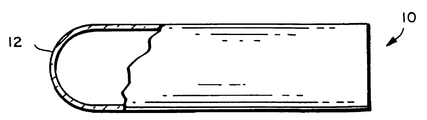
유리관을 다른 유리관에 결합하기 위해 사전 제조하는 방법이 도 1 내지 도 4를 참조하여 설명된다. 상기 방법은 원하는 직경, 벽 두께 및 조성을 갖는 직선형 유리관(10)으로부터 시작된다. 도 2에 도시된 바와 같이, 돔(12)이 유리관(10)의 일단부상에 형성된다. 상기 돔(12)은 선반내에 유리관을 배치하고, 돔이 형성될 영역내에서 유리관을 가열하고, 유리관을 회전시키며, 유리관의 단부들을 서로 먼쪽으로 잡아 당김으로써 형성될 수 있다. 돔(12)을 형성하기 위한 자동화된 기술은 종래 기술로 공지되어 있다. 바람직하게, 상기 돔은 유리관(10)의 직경과 동일한 직경을 가지는 반구 형태를 가진다. 상기 돔(12)은 유리관(10)의 일단부를 폐쇄한다.A method of prefabricating a glass tube for joining it to another glass tube is described with reference to FIGS. The method starts with a
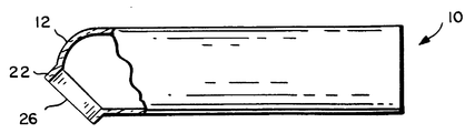
도 3에 도시된 바와 같이, 상기 돔(12)은 림형(rimmed) 홀의 전구체(precursor)를 형성하는 형태를 갖는다. 상기 돔(12)은 블리스터(blister)(20)를 형성하기 위해 몰딩 방법, 이를테면 블로우(blow) 몰딩을 사용하여 성형될 수 있다. 상기 블리스터(20)는 폐쇄된 단부(24)를 가지는 림(22)을 구비한다. 상기 블리스터(20)는 돔(12)을 가열하고 돔(12)의 일부가 블리스터(20)의 형태를 가지는 몰드(도시 안됨)내로 들어가도록 유리관(10)의 내부를 가압함으로써 형성될 수 있다. 상기 몰드는 블리스터(20)의 외부 크기와 형태를 한정한다. 상기 림(22)의 벽 두께는 돔(12)의 두께에 의해 결정되고, 전형적으로 유리관(10)의 벽 두께와 거의 동일하다.As shown in FIG. 3, the
도 4에 도시된 바와 같이, 상기 블리스터(20)의 폐쇄된 단부는 림(22)에 의해 한정된 홀(26)을 형성하기 위해 제거된다. 바람직한 실시예에서, 상기 홀(26)은 불꽃 절단에 의해 블리스터(20)를 통해 형성된다. 바람직하게, 상기 림(22)은 실린더형 벽을 포함하고 원형 홀을 한정한다. 상기 홀(26)의 림(22)은 돔(12)상의 어떤 원하는 위치내에서도 형성될 수 있다. 둥근 림을 보장하기 위하여, 상기 블리스터(20)는 완전히 돔(12)상에 배치되어야 한다. 홀(26)의 위치설정 자유도는 홀(26)의 원하는 크기에 의존한다. 작은 홀은 큰 홀보다 돔 상의 더 큰 입체각내에 위치될 수 있다. 그럼에도 불구하고, 도 1 내지 도 4에 도시되고 위에서 설명된 상기 방법은 홀(26)의 크기와 위치 및 유리관(10)의 축에 관련한 홀의 방향성에 대한 융통성을 제공한다. 림(22)이 몰딩되기 때문에, 림의 형태와 치수는 잘 제어된다.As shown in FIG. 4, the closed end of the
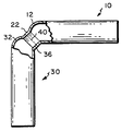
본 발명의 처리 방법을 사용하여 2개 유리관을 결합시키는 것이 도 5에 도시되어 있다. 돔(32)과 림(36)을 가지는 유리관(30)은 이미 기술된 유리관(10)과 같은 동일한 방식으로 처리된다. 상기 림을 형성하는데 사용되는 몰딩 방법의 결과로서 상기 림(22와 36)은 바람직하게 약 0.2 내지 0.3 ㎜이내의 동일한 직경 및 동일한 벽 두께를 가진다. 상기 림(22와 36)은 수 도(°)내로 정렬되고 시일링 결합부(40)를 형성하기 위해 서로 용융된다. 상기 림(22와 36)이 동일한 몰드로 형성되기 때문에, 이들은 밀접하게 정합되고 관(10과 30) 사이의 정확한 용융과 시일링을 허용한다. 상기 관(10과 30)은 전형적으로 동일한 직경과 벽 두께를 가진다. 그러나, 서로 다른 직경의 관도 본 발명의 방법을 사용하여 결합될 수 있다. 기본적으로 필요한 사항은 상기 림(22와 36)이 서로 용융될 수 있도록 충분히 정합되는 것에 있다. 림(22와 36)의 용융은 종래에 공지된 바와 같이 이러한 부재들을 용융 상태까지 가열하고 서로 이들을 가압함으로써 수행된다. Joining two glass tubes using the treatment method of the present invention is shown in FIG. 5. The
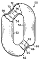
도 1 내지 도 4에 도시되고 이미 개시된 상기 방법은 일단부에 형성된 돔을 가지는 직선 유리관 상에서 수행된다. 많은 경우에, 예를 들어 림(22)의 평면이 유리관(10)의 축에 평행한 방향이 될 수 있도록 돔(12)에 인접한 유리관을 벤딩하는 것이 요구될 수 있다. 아래에 기술되는 바와 같이, 도 1 내지 도 4의 방법은 2개 유리관의 양쪽 단부 상에서 수행될 수 있고 상기 2개 유리관은 폐루프 밀봉체를 형성하기 위해 서로 결합될 수 있다. 이미 개시된 상기 방법은 직선형 및 소정 형상의 유리관에 사용될 수 있다. 개시된 방법과 다른 관 형태 및 크기를 사용하여, 많은 다양한 램프 구성물이 제조된다. 상기 개시된 절차는 매우 작은 개조를 통해 서로 다른 형태 및 크기를 취급할 수 있는 매우 융통성 있는 제조 방법을 허용한다. 본 발명에 따라 제조된 관형 중공 폐루프 램프 밀봉체의 예가 도 6과 도 7에 도시되어 있다. 도 6에서, 램프 밀봉체(50)는 유리관(52와 54)을 결합함으로써 형성된다. 유리관(52)에서, 림(56)은 유리관(52) 일단부의 돔(58)에 형성되고, 림(60)은 유리관(52)의 타단부의 돔(62)에 형성된다. 유사하게, 림(66)은 유리관(54) 일단부의 돔(68)에 형성되고, 림(70)은 유리관(54) 타단부의 돔(72)에 형성된다. 각각의 유리관(52와 54)은 폐루프 램프 밀봉체의 형태를 허용하고 원하는 형태를 제공하도록 일단부 근처에서 형상화된다. 시일링된 폐루프 램프 밀봉체(50)를 형성하기 위하여 유리관(52)의 림(56)은 결합부(76)에서 유리관(54)의 림(70)에 결합되고, 유리관(52) 림(60)은 결합부(78)에서 유리관(54) 림(66)에 결합된다.The method shown in FIGS. 1-4 and already disclosed is carried out on a straight glass tube with a dome formed at one end. In many cases, it may be desired to bend the glass tube adjacent to the
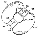
램프 밀봉체(50)와는 서로 다른 형태를 가지지만 동일 방법에 의해 제조되는 램프 밀봉체(90)가 도 7에 도시되어 있다. 유리관(92)은 림(94와 96)을 구비하도록 제조되고, 유리관(100)은 이미 기술된 바와 같이 림(102와 104)을 구비하도록 제조된다. 시일링된 폐루프 램프 밀봉체(90)를 형성하기 위하여 림(96)은 접합부(110)에서 림(104)에 용융되고, 림(94)은 접합부(112)에서 림(102)에 용융된다. 무전극 광원을 위한 램프 밀봉체(120)의 바람직한 구성이 도 8에 도시되어 있다. 상기 램프 밀봉체(120)는 폐루프를 형성하기 위해 브리지(126과 128)에 의해 각각의 단부 또는 근처에 결합되는 유리관(122와 124)을 포함한다. 브리지(126과 128)는 유리관(122와 124)상의 절반 브리지들을 통합함으로써 형성된다. 유리관(122와 124)의 직선 부분들은 서로 평행하고 떨어져 배치된다. 상기 유리관(122와 124)은 폐루프 방전 경로를 가지는 시일링된 램프 밀봉체를 형성하기 위해 접합부(130과 132)에서 용융된다. 바람직한 일 실시예에서, 상기 관(122와 124)은 5.0 ㎝의 외부 직경을 가지고, 브리지(126와 128)에서만 제외하고 2.8 ㎝ 만큼 떨어져 배치된다. 관상부(tubulation)를 제외한 상기 램프 밀봉체의 전체 길이는 40.0 ㎝이다. 상기 브리지(126과 128)는 3.4 ㎝의 외부 직경을 가진다.A lamp seal 90 having a different form from the
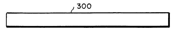
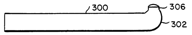
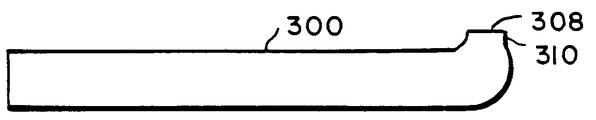
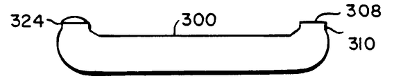
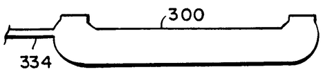
도 8에 도시된 형태의 중공형 폐루프 램프 밀봉체를 제조하기 위한 방법이 도 9와 도 10a 내지 도 10k를 참조하여 개시되어 있다. 이런 방법은 일반적으로 서로 다른 형태와 크기의 관형 폐루프 램프 밀봉체의 제조에 적용될 수 있다는 것을 이해할 것이다. 유리관(300)(도 10a)은 단계(200)에서 원하는 길이로 절단된다. 단계(202)에서 돔(302)(도 10b)이 유리관(300)의 제 1 단부내에 형성된다. 상기 튜브(300)의 돔 단부는 도 10c에서 304로 표시된 바와 같이 단계(204)에서 관축에 대해 40°각도로 벤딩된다. 상기 제 1 단부(302)는 블리스터(306)(도 10d)를 형성하도록 블로우 몰딩법을 사용하여 몰딩된다. 상기 블리스터는 단계(208)에서 림(310)에 의해 한정된 홀(308)(도 10e)을 형성하도록 개방된다. 다음에, 단계(210)에서 돔(320)(도 10f)이 관(300)의 제 2 단부에 형성된다. 단계(212)에서 관(300)의 제 2 단부는 관축에 대해 45°각도로 도 10g에서 322로 표시되는 바와 같이 벤딩된다. 상기 관(300)의 제 2 단부는 단계(214)에서 블리스터(324)(도 10h)를 형성하도록 블로우 몰딩된다. 상기 블리스터(324)는 단계(216)에서 림(328)에 의해 한정된 홀(326)(도 10i)을 형성하도록 개방된다. 상기 램프 밀봉체가 형광 램프에 사용될 때, 상기 유리관(300)의 내부 표면은 단계(218)에서 인광 물질로 코팅된다. 특히, 산화 알루미늄 장벽(barrier) 코팅을 사용하여 상기 램프 관의 내부를 코팅할 수 있다. 상기 장벽 코팅의 오븐 건조후, 상기 램프 관은 종래의 기술에서 공지된 바와 같이 3500K 트리포스포 블랜드(triphosphor blend)로 코팅되고, 건조되며 베이킹된다. 상기 인광 물질 코팅은 유리 시일(seal)이 형성될 림(310과 328)에 인접한 영역내에 유리관(300)의 개방 단부로부터 닦여진다(wipe). 다음에, 단계(220)에서, 제 2 유리관(340)(도 10k)을 위해 단계(200) 내지 단계(218)가 반복된다. 각각의 관은 각각의 단부에 절반 브리지를 가진다. 하나 이상의 배기관(334)(도 10j)은 형성된 유리관 중 어느 하나 또는 양쪽에 부착될 수 있다. 상기 2개 형성된 유리관(300과 340)은 단계(224)에서 폐루프 램프 밀봉체(도 10k)를 형성하도록 결합 장치상에서 이들의 정합 림에서 서로 용융된다.A method for manufacturing a hollow closed loop lamp seal of the type shown in FIG. 8 is disclosed with reference to FIGS. 9 and 10A-10K. It will be appreciated that this method may be applied to the manufacture of tubular closed loop lamp seals of different shapes and sizes in general. Glass tube 300 (FIG. 10A) is cut to the desired length in
램프의 배기 과정은 다른 형광 램프에 대해 사용되는 것과 유사하다. 유리와 인광 물질의 가스를 배기하기 위해 오븐에서 가열되는 동안, 상기 램프 밀봉체는 불활성 가스를 사용한 플러싱(flushing)과 배기의 반복된 주기를 겪게 된다. 크립톤이 될 수 있는 최종 충진 가스는 바람직하게 0.2 torr의 압력에서 유입된다. 소량의 수은과 아말감이 유입되고, 상기 배기관(334)은 도 8에 도시된 바와 같이 완성된 램프 밀봉체를 제공하도록 끝을 절단하여 마감처리(tip off)된다.The exhaust process of the lamp is similar to that used for other fluorescent lamps. While being heated in an oven to evacuate glass and phosphor gases, the lamp seal undergoes repeated cycles of flushing and evacuation with an inert gas. The final fill gas which can be krypton is preferably introduced at a pressure of 0.2 torr. A small amount of mercury and amalgam is introduced and the
절반 브리지 사이의 정확한 간격과 절단 개방 단부의 평면성은 유리관들을 서로에 대해 시일링하는 능력에 중요하다. 상기 절반 브리지상의 림은 약 0.2 내지 0.3 ㎜내로 정렬되어야 하고 수 도(°)내로 동일 평면이 되어야 한다. 상기 유리관의 양쪽 단부는 바람직하게 동시에 시일링된다.The precise spacing between the half bridges and the planarity of the cut open ends are important for the ability to seal the glass tubes against each other. The rim on the half bridge should be aligned within about 0.2 to 0.3 mm and coplanar within degrees (°). Both ends of the glass tube are preferably sealed at the same time.
이상에서는 본 발명의 양호한 일 실시예에 따라 본 발명이 설명되었지만, 첨부된 청구 범위에 의해 한정되는 바와 같은 본 발명의 사상을 일탈하지 않는 범위 내에서 다양한 변형이 가능함은 본 발명이 속하는 기술 분야의 당업자에게는 명백하다.Although the present invention has been described above in accordance with one preferred embodiment of the present invention, various modifications may be made without departing from the spirit of the present invention as defined by the appended claims. It is obvious to those skilled in the art.
본 발명을 이용함으로써 무전극 저압 광원, 특히 관형 폐루프 램프 밀봉체 및 그 제조 방법을 제공한다.The present invention provides an electrodeless low pressure light source, in particular a tubular closed loop lamp seal and a method of manufacturing the same.
도 1 내지 도 4는 본 발명에 따라서 유리관을 다른 유리관에 결합하기 위해 사전 제조하는 과정을 도시하는 도면.1-4 illustrate a process of prefabricating a glass tube in order to bond it to another glass tube in accordance with the present invention.
도 5는 본 발명에 따라서 2개 유리관을 결합하는 것을 도시하는 도면.5 shows joining two glass tubes in accordance with the present invention.
도 6과 도 7은 본 발명에 따라서 제조되는 관형 폐루프 램프 밀봉체를 도시하는 도면.6 and 7 show tubular closed loop lamp seals made in accordance with the present invention.
도 8은 무전극 형광 램프에 사용하기 위한 관형 폐루프 램프 밀봉체의 바람직한 실시예를 도시하는 도면.8 shows a preferred embodiment of a tubular closed loop lamp seal for use in an electrodeless fluorescent lamp.
도 9는 본 발명에 따라서 관형 폐루프 램프 밀봉체를 제조하기 위한 방법을 도시하는 순서도.9 is a flow chart illustrating a method for producing a tubular closed loop lamp seal in accordance with the present invention.
도 10a 내지 도 10k는 도 9의 개별 단계에 수반하는 유리관을 도시하는 도면.10A to 10K illustrate the glass tubes involved in the individual steps of FIG. 9.
* 도면의 주요부분에 대한 부호의 설명 *Explanation of symbols on the main parts of the drawings
120 : 램프 밀봉체 122, 124 : 유리관 120:
126, 128 : 브리지 126, 128: bridge
Claims (21)
Applications Claiming Priority (2)
| Application Number | Priority Date | Filing Date | Title |
|---|---|---|---|
| US08/650,245 US5722549A (en) | 1996-05-22 | 1996-05-22 | Closed-loop tubular lamp envelope and method of manufacture |
| US08/650,245 | 1996-05-22 |
Publications (2)
| Publication Number | Publication Date |
|---|---|
| KR970077069A KR970077069A (en) | 1997-12-12 |
| KR100459777B1 true KR100459777B1 (en) | 2005-02-28 |
Family
ID=24608095
Family Applications (1)
| Application Number | Title | Priority Date | Filing Date |
|---|---|---|---|
| KR1019970019658A KR100459777B1 (en) | 1996-05-22 | 1997-05-21 | Closed-loop tubular lamp envelope and method of manufacture |
Country Status (9)
| Country | Link |
|---|---|
| US (2) | US5722549A (en) |
| EP (1) | EP0808807B1 (en) |
| JP (1) | JP3987603B2 (en) |
| KR (1) | KR100459777B1 (en) |
| CN (1) | CN1089480C (en) |
| CA (1) | CA2205707C (en) |
| DE (1) | DE69710812T2 (en) |
| HU (1) | HU218812B (en) |
| TW (1) | TW479263B (en) |
Cited By (1)
| Publication number | Priority date | Publication date | Assignee | Title |
|---|---|---|---|---|
| KR100727040B1 (en) | 2005-09-09 | 2007-06-12 | 금호전기주식회사 | Lamp envelope manufacturing method for Dual Bridge Electrodeless Fluorescent Lamp |
Families Citing this family (12)
| Publication number | Priority date | Publication date | Assignee | Title |
|---|---|---|---|---|
| US6391809B1 (en) * | 1999-12-30 | 2002-05-21 | Corning Incorporated | Copper alumino-silicate glasses |
| KR20020080787A (en) * | 2001-04-17 | 2002-10-26 | 강성진 | Electrodeless fluorescent lamp having 3-dimensional structure |
| KR100729282B1 (en) * | 2004-07-15 | 2007-06-20 | 조정열 | Method of manufacturing external electrode fluorescent lamps having various shapes and sizes and glass tube unit structure used for the method |
| DE102004034807A1 (en) * | 2004-07-19 | 2006-03-16 | Ip2H Ag | Light source and a method for mechanical stabilization of the filament or the electrode of a light source |
| JP4798009B2 (en) * | 2007-01-26 | 2011-10-19 | パナソニック電工株式会社 | Electrodeless discharge lamp apparatus and lighting fixture |
| JP4956224B2 (en) * | 2007-02-23 | 2012-06-20 | パナソニック株式会社 | Manufacturing method of electrodeless discharge lamp, electrodeless discharge lamp manufactured by the manufacturing method, and lighting fixture using the electrodeless discharge lamp |
| JP2008282743A (en) * | 2007-05-11 | 2008-11-20 | Nippo Electric Co Ltd | Illumination lamp |
| JP2009151969A (en) * | 2007-12-19 | 2009-07-09 | Hoya Candeo Optronics株式会社 | Excimer lamp, its manufacturing method, and light source |
| KR100912666B1 (en) * | 2008-01-04 | 2009-08-17 | 금호전기주식회사 | Method of manufacturing electrodeless fluorescent lamp bulbs |
| KR100917017B1 (en) * | 2008-01-08 | 2009-09-10 | 금호전기주식회사 | electrodeless fluorescent lamp bulbs with surface processing |
| CN102468113B (en) * | 2010-10-28 | 2015-06-24 | 烟台茂翔电子科技有限公司 | Lamp tube for electrodeless lamp and normal temperature connection method thereof |
| DE102019217150A1 (en) * | 2019-11-06 | 2021-05-06 | De Dietrich Process Systems Gmbh | Glass surface for a glass vessel, its manufacture and use |
Citations (4)
| Publication number | Priority date | Publication date | Assignee | Title |
|---|---|---|---|---|
| US4324447A (en) * | 1979-04-03 | 1982-04-13 | U.S. Philips Corporation | Method of producing a low-pressure mercury vapor discharge lamp |
| JPS6465747A (en) * | 1987-09-04 | 1989-03-13 | Matsushita Electric Works Ltd | Manufacture of electrodeless discharge lamp |
| JPH03252027A (en) * | 1990-02-28 | 1991-11-11 | Toshiba Lighting & Technol Corp | How to manufacture fluorescent lamps |
| EP0622831A1 (en) * | 1993-04-27 | 1994-11-02 | Mass Technology (H.K.) Ltd. | Method of producing a low pressure mercury vapour discharge lamp |
Family Cites Families (23)
| Publication number | Priority date | Publication date | Assignee | Title |
|---|---|---|---|---|
| US2392785A (en) * | 1945-03-28 | 1946-01-08 | Sylvania Electric Prod | Lamp base |
| FR1139622A (en) * | 1966-08-01 | 1957-07-03 | Du Pont | PH adjustment in electrolytic deposition processes |
| US3500118A (en) * | 1967-07-17 | 1970-03-10 | Gen Electric | Electrodeless gaseous electric discharge devices utilizing ferrite cores |
| US4027363A (en) * | 1973-06-22 | 1977-06-07 | Belknap Donald J | Methods of making incandescent lamps |
| US3987334A (en) * | 1975-01-20 | 1976-10-19 | General Electric Company | Integrally ballasted electrodeless fluorescent lamp |
| HU174714B (en) * | 1977-01-06 | 1980-03-28 | Egyesuelt Izzolampa | Electric discharge tube |
| US4121132A (en) * | 1977-09-28 | 1978-10-17 | Westinghouse Electric Corp. | Phosphor coating method and resulting fluorescent lamp |
| JPS59103245A (en) * | 1982-12-06 | 1984-06-14 | Mitsubishi Electric Corp | Manufacturing process for discharge lamp |
| JPS61224236A (en) * | 1985-03-27 | 1986-10-04 | Toshiba Corp | Manufacture of curved fluorescent lamp |
| US4787865A (en) * | 1986-12-04 | 1988-11-29 | North American Philips Lighting Corp. | Three-way lamp bases and method for making them |
| US4850500A (en) * | 1986-12-18 | 1989-07-25 | Gte Products Corporation | Dimpled arc tube having no internal end pockets and a lamp employing same |
| JPS6379730A (en) * | 1987-03-06 | 1988-04-09 | Toshiba Corp | Joining method for glass pipe |
| US4864194A (en) * | 1987-05-25 | 1989-09-05 | Matsushita Electric Works, Ltd. | Electrodeless discharge lamp device |
| KR920003545B1 (en) * | 1987-07-01 | 1992-05-02 | 가부시끼가이샤 도시바 | Ring-shaped glass bulb and lamp assembly using the same |
| US5124618A (en) * | 1989-11-16 | 1992-06-23 | Matsushita Electronics Corporation | Shatter-proof fluorescent lamp |
| DE4202485A1 (en) * | 1992-01-27 | 1993-07-29 | Dieter Krebs | Mfg. low pressure gas discharge lamp envelope - forming four parallel section tubes by fusing ends together with aid of glass solder |
| JP3408588B2 (en) * | 1993-09-22 | 2003-05-19 | 池田電機株式会社 | Electrodeless discharge lamp lighting device |
| JPH0794152A (en) * | 1993-09-27 | 1995-04-07 | Ikeda Electric Co Ltd | Electrodeless discharge lamp |
| DE4403260A1 (en) * | 1994-02-03 | 1995-08-10 | Dieter Strueber | Mfr. of electrical gas-discharge lamps |
| BE1007913A3 (en) * | 1993-12-24 | 1995-11-14 | Philips Electronics Nv | Low-pressure discharge lamp and method for manufacturing a low-pressure discharge lamp. |
| US5723939A (en) * | 1994-12-28 | 1998-03-03 | Matsushita Electronics Corporation | Circular fluorescent lamp |
| US5834905A (en) * | 1995-09-15 | 1998-11-10 | Osram Sylvania Inc. | High intensity electrodeless low pressure light source driven by a transformer core arrangement |
| JP2912863B2 (en) * | 1995-11-27 | 1999-06-28 | 松下電子工業株式会社 | Manufacturing method of annular fluorescent lamp |
-
1996
- 1996-05-22 US US08/650,245 patent/US5722549A/en not_active Expired - Lifetime
-
1997
- 1997-04-02 TW TW086104236A patent/TW479263B/en not_active IP Right Cessation
- 1997-05-12 DE DE69710812T patent/DE69710812T2/en not_active Expired - Lifetime
- 1997-05-12 EP EP97107737A patent/EP0808807B1/en not_active Expired - Lifetime
- 1997-05-20 CA CA002205707A patent/CA2205707C/en not_active Expired - Fee Related
- 1997-05-21 KR KR1019970019658A patent/KR100459777B1/en not_active IP Right Cessation
- 1997-05-21 HU HU9700929A patent/HU218812B/en not_active IP Right Cessation
- 1997-05-22 CN CN97113440.5A patent/CN1089480C/en not_active Expired - Lifetime
- 1997-05-22 JP JP13222497A patent/JP3987603B2/en not_active Expired - Fee Related
- 1997-09-26 US US08/938,114 patent/US5932961A/en not_active Expired - Lifetime
Patent Citations (4)
| Publication number | Priority date | Publication date | Assignee | Title |
|---|---|---|---|---|
| US4324447A (en) * | 1979-04-03 | 1982-04-13 | U.S. Philips Corporation | Method of producing a low-pressure mercury vapor discharge lamp |
| JPS6465747A (en) * | 1987-09-04 | 1989-03-13 | Matsushita Electric Works Ltd | Manufacture of electrodeless discharge lamp |
| JPH03252027A (en) * | 1990-02-28 | 1991-11-11 | Toshiba Lighting & Technol Corp | How to manufacture fluorescent lamps |
| EP0622831A1 (en) * | 1993-04-27 | 1994-11-02 | Mass Technology (H.K.) Ltd. | Method of producing a low pressure mercury vapour discharge lamp |
Cited By (1)
| Publication number | Priority date | Publication date | Assignee | Title |
|---|---|---|---|---|
| KR100727040B1 (en) | 2005-09-09 | 2007-06-12 | 금호전기주식회사 | Lamp envelope manufacturing method for Dual Bridge Electrodeless Fluorescent Lamp |
Also Published As
| Publication number | Publication date |
|---|---|
| JP3987603B2 (en) | 2007-10-10 |
| CN1173606A (en) | 1998-02-18 |
| JPH1050218A (en) | 1998-02-20 |
| DE69710812T2 (en) | 2002-09-26 |
| CA2205707C (en) | 2006-01-10 |
| DE69710812D1 (en) | 2002-04-11 |
| HU9700929D0 (en) | 1997-07-28 |
| HUP9700929A2 (en) | 1997-12-29 |
| US5722549A (en) | 1998-03-03 |
| EP0808807A1 (en) | 1997-11-26 |
| KR970077069A (en) | 1997-12-12 |
| HU218812B (en) | 2000-12-28 |
| TW479263B (en) | 2002-03-11 |
| EP0808807B1 (en) | 2002-03-06 |
| HUP9700929A3 (en) | 1999-09-28 |
| CN1089480C (en) | 2002-08-21 |
| CA2205707A1 (en) | 1997-11-22 |
| US5932961A (en) | 1999-08-03 |
Similar Documents
| Publication | Publication Date | Title |
|---|---|---|
| KR100459777B1 (en) | Closed-loop tubular lamp envelope and method of manufacture | |
| JPS6349334B2 (en) | ||
| JP4709361B2 (en) | Ceramic arc tube | |
| US4881007A (en) | Compact gas discharge tube and a method for its manufacture | |
| EP0113485B1 (en) | Method of manufacturing a low-pressure mercury vapour discharge lamp and low-pressure mercury vapour discharge lamp manufactured by this method | |
| CA1065611A (en) | Method of manufacturing an article containing at least one glass part in which a metal part is sealed in | |
| US4086075A (en) | Method of manufacturing an article containing at least one glass part in which a metal part is sealed in | |
| JP2001006549A (en) | Manufacture of arc tube for discharge lamp device and arc tube | |
| JPH02183961A (en) | Halogen incandescent lamp and manufacture thereof | |
| KR100684505B1 (en) | Single bridge electrodeless fluorescent lamp and manufacturing method thereof | |
| JP3218958B2 (en) | Annular fluorescent lamp and method of manufacturing the same | |
| EP0559421B1 (en) | Seal construction arrangement for an electrodeless high intensity discharge lamp | |
| KR100727040B1 (en) | Lamp envelope manufacturing method for Dual Bridge Electrodeless Fluorescent Lamp | |
| US5833506A (en) | Method for manufacturing a fluorescent lamp | |
| KR101227766B1 (en) | Electric lamp with inner assembly and outer bulb and method for manufacturing | |
| JPH09180682A (en) | Fluorescent lamp and manufacture thereof | |
| JP4798009B2 (en) | Electrodeless discharge lamp apparatus and lighting fixture | |
| JPH0138053B2 (en) | ||
| KR20090076301A (en) | Electrodeless fluorescent lamp bulbs with surface processing | |
| KR100912666B1 (en) | Method of manufacturing electrodeless fluorescent lamp bulbs | |
| CA1162970A (en) | Envelope seal structure for metal vapor arc lamp | |
| JPS61260542A (en) | Low pressure mercury vapor discharge lamp | |
| JPS62154431A (en) | Sealing method for bend type fluorescent lamp | |
| JP3673949B2 (en) | Electrodeless fluorescent discharge lamp | |
| JP2008186607A (en) | Electrodeless discharge lamp device and lighting fixture |
Legal Events
| Date | Code | Title | Description |
|---|---|---|---|
| A201 | Request for examination | ||
| E902 | Notification of reason for refusal | ||
| E701 | Decision to grant or registration of patent right | ||
| GRNT | Written decision to grant | ||
| FPAY | Annual fee payment |
Payment date: 20121116 Year of fee payment: 9 |
|
| FPAY | Annual fee payment |
Payment date: 20131114 Year of fee payment: 10 |
|
| FPAY | Annual fee payment |
Payment date: 20141113 Year of fee payment: 11 |
|
| FPAY | Annual fee payment |
Payment date: 20151112 Year of fee payment: 12 |
|
| FPAY | Annual fee payment |
Payment date: 20161111 Year of fee payment: 13 |
|
| EXPY | Expiration of term |