KR100312902B1 - Diagnostic system for fiber grating sensors - Google Patents
Diagnostic system for fiber grating sensors Download PDFInfo
- Publication number
- KR100312902B1 KR100312902B1 KR1019970703535A KR19970703535A KR100312902B1 KR 100312902 B1 KR100312902 B1 KR 100312902B1 KR 1019970703535 A KR1019970703535 A KR 1019970703535A KR 19970703535 A KR19970703535 A KR 19970703535A KR 100312902 B1 KR100312902 B1 KR 100312902B1
- Authority
- KR
- South Korea
- Prior art keywords
- sensor
- wavelength
- light
- tuner control
- signal
- Prior art date
Links
- 239000000835 fiber Substances 0.000 title description 12
- 230000003287 optical effect Effects 0.000 claims abstract description 36
- 238000001514 detection method Methods 0.000 claims abstract description 24
- 230000003068 static effect Effects 0.000 claims abstract description 20
- 230000005540 biological transmission Effects 0.000 claims abstract description 16
- 238000000034 method Methods 0.000 claims description 30
- 230000004044 response Effects 0.000 claims description 29
- 230000008859 change Effects 0.000 claims description 17
- 230000008878 coupling Effects 0.000 claims description 14
- 238000010168 coupling process Methods 0.000 claims description 14
- 238000005859 coupling reaction Methods 0.000 claims description 14
- 241000143252 Idaea infirmaria Species 0.000 claims 1
- 239000013307 optical fiber Substances 0.000 abstract description 36
- 230000006870 function Effects 0.000 description 11
- 238000001228 spectrum Methods 0.000 description 4
- 238000010586 diagram Methods 0.000 description 3
- 230000000694 effects Effects 0.000 description 3
- 239000000463 material Substances 0.000 description 3
- 239000000203 mixture Substances 0.000 description 3
- 239000002184 metal Substances 0.000 description 2
- 238000012544 monitoring process Methods 0.000 description 2
- 239000004033 plastic Substances 0.000 description 2
- 230000035945 sensitivity Effects 0.000 description 2
- 230000003321 amplification Effects 0.000 description 1
- 238000004458 analytical method Methods 0.000 description 1
- 239000011248 coating agent Substances 0.000 description 1
- 238000000576 coating method Methods 0.000 description 1
- 230000008602 contraction Effects 0.000 description 1
- 230000007423 decrease Effects 0.000 description 1
- 238000005516 engineering process Methods 0.000 description 1
- 230000008450 motivation Effects 0.000 description 1
- 238000003199 nucleic acid amplification method Methods 0.000 description 1
- 230000010355 oscillation Effects 0.000 description 1
- 230000001151 other effect Effects 0.000 description 1
- 230000000737 periodic effect Effects 0.000 description 1
- 238000005316 response function Methods 0.000 description 1
- 238000000926 separation method Methods 0.000 description 1
- 230000009131 signaling function Effects 0.000 description 1
- 230000003595 spectral effect Effects 0.000 description 1
- 239000000126 substance Substances 0.000 description 1
- 230000009897 systematic effect Effects 0.000 description 1
- 230000007704 transition Effects 0.000 description 1
Images


Classifications
-
- G—PHYSICS
- G01—MEASURING; TESTING
- G01D—MEASURING NOT SPECIALLY ADAPTED FOR A SPECIFIC VARIABLE; ARRANGEMENTS FOR MEASURING TWO OR MORE VARIABLES NOT COVERED IN A SINGLE OTHER SUBCLASS; TARIFF METERING APPARATUS; MEASURING OR TESTING NOT OTHERWISE PROVIDED FOR
- G01D5/00—Mechanical means for transferring the output of a sensing member; Means for converting the output of a sensing member to another variable where the form or nature of the sensing member does not constrain the means for converting; Transducers not specially adapted for a specific variable
- G01D5/26—Mechanical means for transferring the output of a sensing member; Means for converting the output of a sensing member to another variable where the form or nature of the sensing member does not constrain the means for converting; Transducers not specially adapted for a specific variable characterised by optical transfer means, i.e. using infrared, visible, or ultraviolet light
- G01D5/32—Mechanical means for transferring the output of a sensing member; Means for converting the output of a sensing member to another variable where the form or nature of the sensing member does not constrain the means for converting; Transducers not specially adapted for a specific variable characterised by optical transfer means, i.e. using infrared, visible, or ultraviolet light with attenuation or whole or partial obturation of beams of light
- G01D5/34—Mechanical means for transferring the output of a sensing member; Means for converting the output of a sensing member to another variable where the form or nature of the sensing member does not constrain the means for converting; Transducers not specially adapted for a specific variable characterised by optical transfer means, i.e. using infrared, visible, or ultraviolet light with attenuation or whole or partial obturation of beams of light the beams of light being detected by photocells
- G01D5/353—Mechanical means for transferring the output of a sensing member; Means for converting the output of a sensing member to another variable where the form or nature of the sensing member does not constrain the means for converting; Transducers not specially adapted for a specific variable characterised by optical transfer means, i.e. using infrared, visible, or ultraviolet light with attenuation or whole or partial obturation of beams of light the beams of light being detected by photocells influencing the transmission properties of an optical fibre
- G01D5/35306—Mechanical means for transferring the output of a sensing member; Means for converting the output of a sensing member to another variable where the form or nature of the sensing member does not constrain the means for converting; Transducers not specially adapted for a specific variable characterised by optical transfer means, i.e. using infrared, visible, or ultraviolet light with attenuation or whole or partial obturation of beams of light the beams of light being detected by photocells influencing the transmission properties of an optical fibre using an interferometer arrangement
- G01D5/35335—Aspects of emitters or receivers used by an interferometer in an optical fibre sensor arrangement
-
- G—PHYSICS
- G01—MEASURING; TESTING
- G01D—MEASURING NOT SPECIALLY ADAPTED FOR A SPECIFIC VARIABLE; ARRANGEMENTS FOR MEASURING TWO OR MORE VARIABLES NOT COVERED IN A SINGLE OTHER SUBCLASS; TARIFF METERING APPARATUS; MEASURING OR TESTING NOT OTHERWISE PROVIDED FOR
- G01D5/00—Mechanical means for transferring the output of a sensing member; Means for converting the output of a sensing member to another variable where the form or nature of the sensing member does not constrain the means for converting; Transducers not specially adapted for a specific variable
- G01D5/26—Mechanical means for transferring the output of a sensing member; Means for converting the output of a sensing member to another variable where the form or nature of the sensing member does not constrain the means for converting; Transducers not specially adapted for a specific variable characterised by optical transfer means, i.e. using infrared, visible, or ultraviolet light
- G01D5/32—Mechanical means for transferring the output of a sensing member; Means for converting the output of a sensing member to another variable where the form or nature of the sensing member does not constrain the means for converting; Transducers not specially adapted for a specific variable characterised by optical transfer means, i.e. using infrared, visible, or ultraviolet light with attenuation or whole or partial obturation of beams of light
- G01D5/34—Mechanical means for transferring the output of a sensing member; Means for converting the output of a sensing member to another variable where the form or nature of the sensing member does not constrain the means for converting; Transducers not specially adapted for a specific variable characterised by optical transfer means, i.e. using infrared, visible, or ultraviolet light with attenuation or whole or partial obturation of beams of light the beams of light being detected by photocells
- G01D5/353—Mechanical means for transferring the output of a sensing member; Means for converting the output of a sensing member to another variable where the form or nature of the sensing member does not constrain the means for converting; Transducers not specially adapted for a specific variable characterised by optical transfer means, i.e. using infrared, visible, or ultraviolet light with attenuation or whole or partial obturation of beams of light the beams of light being detected by photocells influencing the transmission properties of an optical fibre
- G01D5/35306—Mechanical means for transferring the output of a sensing member; Means for converting the output of a sensing member to another variable where the form or nature of the sensing member does not constrain the means for converting; Transducers not specially adapted for a specific variable characterised by optical transfer means, i.e. using infrared, visible, or ultraviolet light with attenuation or whole or partial obturation of beams of light the beams of light being detected by photocells influencing the transmission properties of an optical fibre using an interferometer arrangement
- G01D5/35309—Mechanical means for transferring the output of a sensing member; Means for converting the output of a sensing member to another variable where the form or nature of the sensing member does not constrain the means for converting; Transducers not specially adapted for a specific variable characterised by optical transfer means, i.e. using infrared, visible, or ultraviolet light with attenuation or whole or partial obturation of beams of light the beams of light being detected by photocells influencing the transmission properties of an optical fibre using an interferometer arrangement using multiple waves interferometer
- G01D5/35312—Mechanical means for transferring the output of a sensing member; Means for converting the output of a sensing member to another variable where the form or nature of the sensing member does not constrain the means for converting; Transducers not specially adapted for a specific variable characterised by optical transfer means, i.e. using infrared, visible, or ultraviolet light with attenuation or whole or partial obturation of beams of light the beams of light being detected by photocells influencing the transmission properties of an optical fibre using an interferometer arrangement using multiple waves interferometer using a Fabry Perot
Abstract
본 발명에 따른 광 센서 진단 시스템은 광섬유(32, 52)내로 가변 파장 광(44)을 제공하는 조정가능한 협파장 대역 광원(9)을 포함한다. 이 광섬유(52)를 따라 가변 광(44)의 경로내에 브래그 격자와 같은 반사 센서(54, 58)가 배치된다. 이들 센서(54, 58)는 그에 인가되는 스트레인과 같은 요인에 기인해 변화하는 최소 전달 파장을 갖는 광(56, 60)을 전달한다. 튜너 제어 회로(42)는 조정가능한 광(44)이 그의 최소 전달 파장으로 각 센서를 조명하기 위해 사전결정된 파장 범위를 통해 스캔하도록 조정가능한 광원(9)을 구동한다. 피전달 광의 파워는 검출기(64)에 의해 전기적 신호로 변환되고, 피전달 파워 레벨의 강하를 검출하여 라인(71)상으로 각 센서에 대한 요인을 표시하는 출력 신호를 제공는 신호 처리기(68)에 의해 모니터된다. 본 시스템은 정적 스트레인을 측정하도록 개방 루프 모드로 구성될 수도 있고 정적 스트레인을 추적하고 동적 스트레인을 측정하도록 폐쇄 루프 모드로 구성될 수도 있다. 또한, 본 시스템은 훼브리-페로트 구성으로 이용되어 매우 민감한 스트레인 검출 시스템을 제공할 수도 있다. 또한, 본 시스템은 반사 또는 전달 모드로 구성될 수 있다.The optical sensor diagnostic system according to the invention comprises an adjustable narrow wavelength band light source 9 which provides variable wavelength light 44 into optical fibers 32, 52. Along the optical fiber 52, reflection sensors 54, 58, such as Bragg gratings, are disposed in the path of the variable light 44. These sensors 54, 58 transmit light 56, 60 having a minimum transmission wavelength that changes due to factors such as strain applied thereto. The tuner control circuit 42 drives the adjustable light source 9 so that the adjustable light 44 scans through a predetermined wavelength range to illuminate each sensor at its minimum transmission wavelength. The power of the transmitted light is converted into an electrical signal by the detector 64 and the signal processor 68 detects a drop in the delivered power level and provides an output signal on line 71 indicating the factor for each sensor. Is monitored. The system may be configured in open loop mode to measure static strain or in closed loop mode to track static strain and measure dynamic strain. The system may also be used in a Fabry-Perot configuration to provide a highly sensitive strain detection system. In addition, the system may be configured in a reflection or transmission mode.
Description
광섬유에 특히 유용한 브래그(Bragg) 격자는, 예를 들어, 멜츠(Meltz) 등에게 특허된 미국 특허 제 4,806,012 호 및 4,761,073 호에 기술된 바와 같이, 격자 위치에서의, 예를 들면, 스트레인 또는 온도와 같은 문제발생 요인을 검출하는데 이용될 수도 있음이 알려졌다. 이러한 센서에서 광섬유 코어는 이 코어내로 발사되는 광의 협파장 대역을 반사하는데 효과적인 주기적 격자 패턴으로 형성된다. 전달 및 반사된 광에 있어서의 스펙트럼 쉬프트는 입사된 광의 연관된 파장에 대응하는 격자의 위치에서의 스트레인 또는 온도 변동의 강도를 표시한다. 그러나, 격자의 반사(또는 전달) 파장 프로화일(또는 스펙트럼)은 격자 영역에 대해 인가된 요인의 함수로서 쉬프트되는 것으로 알려져 있지만, 현재 이러한 광섬유 브래그 격자를 이용하는 실용적인 전체 시스템은 아직 연구된 바가 없다.Bragg gratings that are particularly useful for optical fibers are, for example, strain or temperature at grating locations, as described, for example, in US Pat. Nos. 4,806,012 and 4,761,073 to Meltz et al. It is known that it may be used to detect the same problem factor. In such sensors, the fiber core is formed in a periodic grating pattern that is effective to reflect a narrow wavelength band of light emitted into the core. The spectral shift in the transmitted and reflected light indicates the intensity of the strain or temperature variation at the location of the grating corresponding to the associated wavelength of the incident light. However, although the reflection (or transmission) wavelength profile (or spectrum) of the grating is known to be shifted as a function of the applied factor for the grating region, a practical overall system using this fiber Bragg grating has not yet been studied.
따라서, 정적인 또는 동적인 스트레인, 음향적 요인 또는 다른 요인에 기인해 발생하는 광섬유 브래그 격자의 파장 쉬프트를 검출하는 시스템이 요구된다.Accordingly, what is needed is a system that detects wavelength shifts in optical fiber Bragg gratings caused by static or dynamic strains, acoustical factors or other factors.
본 발명은 광섬유 브래그 격자를 이용하는 시스템에 관한 것으로, 보다 구체적으로, 이러한 광섬유 격자 기술과 함께 이용하기 위한 특정의 시스템 구성에 관한 것이다.The present invention relates to a system using an optical fiber Bragg grating, and more particularly, to a specific system configuration for use with such optical fiber grating technology.
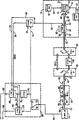
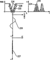
도 1은 본 발명에 따라, 정적인 스트레인을 판정할 수 있는 광섬유 격자 센서 진단 시스템의 제 1 상태의 개략적인 블럭도이다.1 is a schematic block diagram of a first state of a fiber optic grating sensor diagnostic system capable of determining static strain, in accordance with the present invention.
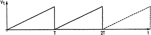
도 2a 내지 2c는 본 발명에 따라, 시간의 함수로서의 튜너에 인가된 전압 Vt을 나타내는 그래프 및 조정된 광원의 출력 파장을 나타내는 그래프와, 시간 및 파장의 함수로서의 출력 파워 스펙트럼을 나타내는 그래프이다.2A-2C are graphs showing the voltage V t applied to the tuner as a function of time and a graph showing the output wavelength of the adjusted light source and a graph showing the output power spectrum as a function of time and wavelength, in accordance with the present invention.
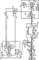
도 3은 본 발명에 따른 도 1에 도시된 튜너 제어 회로의 개략적인 블록도이다.3 is a schematic block diagram of the tuner control circuit shown in FIG. 1 in accordance with the present invention.
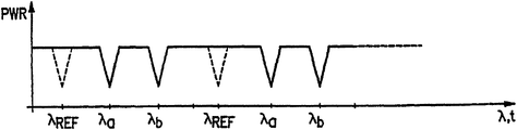
도 4는 본 발명에 따른 격자 센서의 전달 파워 프로화일의 그래프이다.4 is a graph of the transfer power profile of the grating sensor according to the invention.
도 5는 본 발명에 따라, 격자의 전달 파워 프로화일과, 입력 동적 스트레인 신호와, 변조 신호와, 진폭 변조된 출력 센서 신호를 나타내는 그래프이다.5 is a graph showing a transfer power profile of an grating, an input dynamic strain signal, a modulated signal, and an amplitude modulated output sensor signal, in accordance with the present invention.
도 6은 본 발명에 따라, 브래그 격자 센서의 파장 쉬프트를 추적하기 위한 동작의 반사 모드로 구성된 광섬유 격자 센서 진단 시스템의 개략적인 블럭도이다.6 is a schematic block diagram of a fiber optic grating sensor diagnostic system configured in a reflective mode of operation to track wavelength shift of a Bragg grating sensor, in accordance with the present invention.
본 발명의 목적은 브래그 격자 센서를 포함하는 광섬유와 인터페이스하여 정적 및 동적 요인을 판정하는 진단 시스템을 제공하는 것이다.It is an object of the present invention to provide a diagnostic system for interfacing with an optical fiber comprising a Bragg grating sensor to determine static and dynamic factors.
본 발명의 제 1 측면에 따른 광센서 진단 시스템은 튜너 제어 신호에 응답하여 광 도파관내로 발사되는 파장 조정가능한 광을 제공하는 조정가능한 광원 수단과, 이 조정가능한 광의 경로에 배치되어 대응하는 센서에 인가되는 요인에 응답하여 변동하는 연관된 최소 전달 파장을 갖는 피전달 광을 제각기 제공하는 적어도 하나의 광센서 수단을 포함하며, 상기 조정가능한 광원 수단은 상기 연관된 최소 전달 파장으로 상기 각 센서 수단을 개별적으로 조명하고, 상기 조정가능한 광원 수단과 상기 광센서 사이의 상기 조정가능한 광의 경로내에 배치되어 상기 센서 수단으로부터 반사된 광으로부터 상기 조정가능한 광원 수단을 분리하는 광 분리 수단과, 상기 피전달 광의 경로내에 배치되어 상기 각 센서 수단으로부터의 피전달 광원을 검출하고 상기 피전달 광의 파워를 표시하는 전기적 검출 신호를 제공하는 광 검출 수단과, 상기 조정가능한 광원 수단에 상기 조정가능한 광의 소망하는 파장을 표시하는 가변 전압 신호를 제공하는 튜너 제어 수단과, 상기 전기적 검출 신호에 응답하여 상기 요인에 기인한 최소 전달 파장의 쉬프트를 검출하고 상기 각센서 수단에 대한 요인을 표시하는 신호를 제공하는 신호 처리 수단을 또한 포함한다.An optical sensor diagnostic system according to the first aspect of the present invention is provided with adjustable light source means for providing wavelength adjustable light emitted into an optical waveguide in response to a tuner control signal, and applied to a corresponding sensor disposed in the path of the adjustable light. At least one photosensor means for respectively providing a delivered light having an associated minimum transmission wavelength that varies in response to a factor that is caused, wherein the adjustable light source means individually illuminates each sensor means at the associated minimum transmission wavelength. And light separation means arranged in the path of the adjustable light between the adjustable light source means and the light sensor to separate the adjustable light source means from light reflected from the sensor means, and in the path of the delivered light. Detecting a light source to be transmitted from each sensor means and Optical detection means for providing an electrical detection signal indicative of the power of the transmitted light, tuner control means for providing the adjustable light source means with a variable voltage signal indicative of a desired wavelength of the adjustable light, and in the electrical detection signal. Signal processing means for responsively detecting a shift in the minimum propagation wavelength due to said factor and providing a signal indicative of the factor for said angular sensor means.
본 발명의 제 2 측면에 따른 광센서 진단 시스템은 튜너 제어 신호에 응답하여, 광 도파관내로 발사되는 파장 조정가능한 광을 제공하는 조정가능한 광원 수단과, 상기 조정가능한 광의 경로내에 배치되어, 대응하는 센서에 인가되는 요인에 응답하여 변동하는 연관된 국부적 최대 피크 반사 파장을 갖는 피반사 광을 제각기 제공하는 적어도 하나의 광센서 수단을 포함하며, 상기 조정가능한 광원 수단은 상기 연관된 피크 파장으로 상기 각 센서 수단을 개별적으로 조명하고, 상기 조정가능한 광원 수단과 상기 광센서 수단 사이의 상기 조정가능한 광의 경로내에 배치되어 상기 피반사 광으로부터 상기 조정가능한 광원 수단을 분리하는 광 분리 수단과, 상기 피반사 광의 경로내에 배치되어 상기 각 센서 수단으로부터의 피반사 광을 검출하고 상기 피반사 광의 파워를 표시하는 전기적 검출 신호를 제공하는 광검출 수단과, 상기 조정가능한 광원 수단에 상기 조정가능한 광의 소망하는 파장을 표시하는 가변 전압 신호를 제공하는 튜너 제어 수단과, 상기 전기적 검출 신호에 응답하여 상기 요인에 기인한 최소 파장의 쉬프트를 검출하고 상기 요인을 표시하는 신호를 제공하는 신호 처리 수단을 또한 포함한다.An optical sensor diagnostic system according to a second aspect of the present invention comprises adjustable light source means for providing wavelength adjustable light emitted into an optical waveguide, in response to a tuner control signal, and disposed in the path of the adjustable light, such that the corresponding sensor And at least one optical sensor means for respectively providing reflected light having an associated local maximum peak reflection wavelength that varies in response to a factor applied to said adjustable light source means for each said sensor means at said associated peak wavelength. Individually separating and arranged in the path of the adjustable light between the adjustable light source means and the photosensor means to separate the adjustable light source means from the reflected light, and in the path of the reflected light Detect the reflected light from each sensor means and Photodetector means for providing an electrical detection signal indicative of the power of dead light, tuner control means for providing a variable voltage signal indicative of a desired wavelength of said adjustable light to said adjustable light source means, and in response to said electrical detection signal; Signal processing means for detecting a shift in the minimum wavelength attributable to said factor and providing a signal indicative of said factor.
본 발명의 제 3 측면에 따른 광센서 진단 시스템은 튜너 제어 신호에 응답하여, 광 도파관내로 발사되는 파장 조정가능한 광을 제공하는 조정가능한 광원 수단으로서, 상기 광원 수단의 공동의 일단부를 한정하는 전방 가변-파장 반사기를 구비하는 상기 조정가능한 광원 수단과, 상기 조정가능한 광의 경로내에 배치되어,대응하는 센서에 인가되는 요인에 응답하여 변동하는 연관된 피크 반사 파장을 갖는 적어도 하나의 광센서 수단으로서, 상기 전방 반사기와 상기 센서 수단들중 대응하는 센서 사이의 연관된 결합 공동에 대해 반사기로서 동작하는 상기 적어도 하나의 광센서 수단을 포함하며, 상기 결합 공동은 상기 연관된 피크 반사 파장에서 공진하여 상기 피크 파장을 표시하는 출력 광을 제공하고, 상기 요인에 의해 상기 결합 공동을 조정해제하여 상기 출력 광의 파워를 그에 따라 변화시키고, 상기 조정가능한 광원 수단은 상기 연관된 피크 반사 파장으로 상기 각 센서 수단을 개별적으로 조명하며, 상기 출력 광의 경로내에 배치되어 상기 각 센서 수단과 연관된 각 결합 공동으로 부터의 출력 광을 검출하고 상기 출력 광의 파워를 표시하는 전기적 검출 신호를 제공하는 광검출 수단과, 상기 조정가능한 광원 수단에 상기 조정가능한 광의 소망하는 파장을 표시하는 가변 전압 신호를 제공하는 튜너 제어 수단과, 상기 전기적 검출 신호에 응답하여 상기 요인에 기인한 피크 파장의 쉬프트를 검출하고 상기 각 센서 수단에 대한 요인을 표시하는 신호를 제공하는 신호 처리 수단을 또한 포함한다.An optical sensor diagnostic system according to a third aspect of the present invention is an adjustable light source means for providing wavelength adjustable light emitted into an optical waveguide in response to a tuner control signal, the forward variable defining one end of a cavity of the light source means. At least one optical sensor means having said adjustable light source means having a wavelength reflector and an associated peak reflection wavelength disposed in the path of said adjustable light and varying in response to a factor applied to a corresponding sensor, said front Said at least one photosensor means operating as a reflector for an associated coupling cavity between a reflector and a corresponding one of said sensor means, said coupling cavity resonating at said associated peak reflection wavelength to indicate said peak wavelength. Provide output light and de-adjust the coupling cavity by the factor By varying the power of the output light accordingly, the adjustable light source means illuminating each sensor means individually with the associated peak reflecting wavelength, and disposed in the path of the output light to each coupling cavity associated with the respective sensor means. Photodetector means for detecting output light from and providing an electrical detection signal indicative of the power of the output light, and tuner control means for providing said adjustable light source means with a variable voltage signal indicative of a desired wavelength of said adjustable light; And signal processing means for detecting a shift in the peak wavelength due to the factor in response to the electrical detection signal and providing a signal indicative of the factor for each of the sensor means.
본 발명은 원격 광섬유 브래그 격자 센서와 함께 동작하여 브래그 격자 센서 또는 구조물의 정적인 스트레인, 동적 스트레인 및/또는 음향/진동 요인을 검출하도록 기능하는 실용적인 진단 시스템을 제공한다. 이 원격 센서는 금속, 플라스틱, 그의 혼합 또는, 팽창, 수축 또는 진동하는 어떤 다른 재료로 형성된 구조물상에 배치될 수도 있고, 센서는 또한 이러한 구조물내에 포함될 수도 있다. 본 발명은 또한 광섬유 격자에 의해 제어되는 외부 공동을 이용하는 유연하게 파장 조정가능한 레이저 다이오드 전달기를 제공한다. 본 발명은 각 센서를 개별적으로 조명하여 모든 광원 파워가 단일의 파장 또는 협파장 대역내에 놓일 수 있게 한다. 결과적으로, 각 격자로부터의 피반사 또는 피전달 광은 고강도를 가지므로써, 광대역 광원을 이용하여 동시에 모든 센서를 조명하는 시스템보다 훨씬 더 큰, 피반사 또는 피전달 광의 신호 대 노이즈 비를 제공한다.The present invention provides a practical diagnostic system that works with a remote fiber Bragg grating sensor to function to detect static strain, dynamic strain and / or acoustic / vibration factors of the Bragg grating sensor or structure. This remote sensor may be disposed on a structure formed of metal, plastic, a mixture thereof, or any other material that expands, contracts, or vibrates, and the sensor may also be included within such a structure. The present invention also provides a flexible wavelength adjustable laser diode transmitter using an external cavity controlled by an optical fiber grating. The present invention illuminates each sensor individually so that all light source powers lie within a single wavelength or narrow wavelength band. As a result, the reflected or transmitted light from each grating has a high intensity, providing a much larger signal-to-noise ratio of the reflected or transmitted light than a system that simultaneously illuminates all sensors using a broadband light source.
본 발명의 다른 특징은 상기한 시스템 구성을 다른 진단 기능을 실행하도록 절환할 수 있는 능력이다. 본 발명은 폐루프 또는 개루프 전달 모드에서는 물론 반사 모드에서 파장 쉬프트를 검출하는 다양한 실시예를 포함한다. 또한, 본 발명은 결합 공동 훼브리-페로트(Fabry-Perot) 구성으로 구성되어 광 도파관의 다양한 길이를 따른 요인을 검출할 수도 있다.Another feature of the invention is the ability to switch the above system configuration to perform other diagnostic functions. The present invention includes various embodiments for detecting wavelength shifts in the closed or open loop delivery mode as well as in the reflective mode. In addition, the present invention may be configured in a coupling cavity Fabry-Perot configuration to detect factors along various lengths of the optical waveguide.
본 발명의 전술한 목적 및 다른 목적과 특징 및 장점은 이후의 첨부된 도면에 예시된 바와 같은 예시적인 실시예의 설명으로부터 더욱 명백하게 된다.The above and other objects, features and advantages of the present invention will become more apparent from the following description of exemplary embodiments as illustrated in the accompanying drawings.
도 1을 참조하면, 조정가능한 협파장-대역 광원(9)은, 예를 들면, 샤프사에 의해 제조된 제품번호 LTO-15-MDO인 레이저 다이오드(10)를 포함하며, 이 다이오드는 전형적으로 레이저 다이오드 공동 공진기를 한정하는 후면(12) 및 전면(14)을 갖는다. 이 전면(14)은 이후 설명되는 바와 같이 출력광(15)이 전면(14)을 통과할 때 레이저 다이오드 공동내로 되돌아가는 내부 반사 광을 최소화하는 반사방지(an anti-reflection;AR) 코팅으로 피막된다. 전류 제어 회로(16)는 라인(18)을 통해 레이저 다이오드(10)에 출력광(15)의 강도를 제어하는 전류 신호를 제공한다. 이 다이오드를 통해 흐르는 전류를 조정하므로써 또한 파장의 경미한 변화를 초래하지만, 이러한 효과는 본 응용에는 중요하지 않다. 또한, 온도 제어 회로(20)는 라인(22)을 통해 열전기(a thermoelectric;TE) 냉각기(24)에 전압 신호를 제공하여 레이저 다이오드(10)의 온도를 조정하므로써 그로부터 방출되는 출력광(15)의 중심주파수를 조정한다. 원한다면 그밖에 다른 장치가 온도를 제어하는데 이용될 수도 있다.With reference to FIG. 1, the adjustable narrow-band light source 9 comprises a laser diode 10, for example, product number LTO-15-MDO manufactured by Sharp, which typically is a diode. It has a back side 12 and a
레이저 다이오드(10)는 광섬유(32)에 집중된 광(30)을 제공하는 초점 렌즈(28)에 발산 출력광 빔(15)을 제공한다. 이 렌즈(28) 대신에 이와 동일한 기능을 제공하는 임의의 렌즈 시스템이 제공될 수도 있다. 광(30)은 광섬유(32)를 따라, 예를 들면, 브래그 격자와 같은 광섬유 격자(34)로 전파되며, 광섬유 격자는 라인(35)으로 표시된 바와 같이 사전결정된 양의 협파장 대역 광(33)을 반사하고 나머지 파장을 통과시킨다.The laser diode 10 provides a divergent
전면(14)은 앞서 언급된 바와 같이 AR 코팅되어 있으므로, 레이저 다이오드(10)의 후면(12)과 광섬유 격자(34)는 확장된 레이저 다이오드 공동을 형성한다. 광섬유 격자(34)에는 압전기(a piezoelectric;PZT) 액츄에이터(36)(또는 튜너)가 부착되며, 이 액츄에이터는 튜너 제어 회로(42)(이후 설명됨)로 부터의 라인(40)을 통한 가변 전압 신호에 응답하여 화살표(38)로 표시된 바와 같이 팽창 및 수축한다. 튜너(36)는 격자 공간에 변화(굴절률의 변화)를 초래하여 격자의 중심 반사 파장을 변화시킨다. 사실, 이 튜너(36)는 광섬유 격자 공간을 신장 및 수축시켜 공동 미러(12, 34)에 의해 한정되는 레이저의 출력 파장을 변화시킨다. 레이저 다이오드내에서 발생하는 증폭으로 인해 출력광(35)의 최고 파워 파장은 피반사 광(33)의 파장이 된다. 따라서, 출력광(35)의 좁은 레이저 파장은 튜너(36)에 인가되는 라인(40)을 통한 신호의 함수로서 변화한다.Since the
광(35)은 광섬유(32)를 따라 광 스위치(46)로 전파되며, 이 광 스위치는 상태1에 위치되었을 때 광섬유(32)를 광 분리기(48)에 접속시킨다. 광 분리기(48)의 출력은 또 다른 광 스위치(50)에 접속되며, 이 광 스위치(50)는 상태1에 놓였을 때 광 분리기의 출력을 광섬유(52)에 광학적으로 접속시킨다. 이들 광 스위치(46, 50)는 대안적으로 수동 광섬유 패치 코드일 수도 있다.Light 35 propagates along
광(44)은 광섬유(52)를 따라 광섬유 격자(54)로 전파되며, 이 광섬유 격자는 사전결정된 협파장 대역의 광(55)을 반사하고 나머지 파장의 광을 광 빔(56)으로서 통과시킨다. 이 광(56)은 또 다른 광섬유 격자(58)로 보내지며, 광섬유 격자(54)의 파장과 다른 중심 반사 파장을 갖는다. 이 격자(54)는 라인(60)으로 표시된 바와 같이 협파장 대역 광(59)을 반사하고 나머지 파장의 광을 통과시킨다.Light 44 propagates along the
광섬유(52) 및 광섬유 격자(54, 58)는, 예를 들면, 동적 또는 정적 스트레인 및/또는 온도와 같은 요인 변화에 대해 모니터링되는 구조물(62)에 접착 또는 구조물내에 내장될 수도 있다. 이 구조물은 금속, 플라스틱, 그의 혼합물 또는 어떤 다른 재료로 제조될 수 있으며, 센서는 이 구조물상에 또는 구조물내에 배치될 수도 있다. 비록 도 1에는 단지 두 개의 격자(54, 58)가 도시되었지만, 광섬유(52)를 따라 어떤 수의 격자도 위치될 수 있음을 이해해야 한다.
광(60)은 격자(58)로부터 방출되어 광섬유(52)를 따라 광 검출기(64)로 전파된다. 이 광 검출기(64)는 라인(66)을 통해 입사되는 광 파워를 표시하는 전기적 검출 신호를 피드백 제어 회로(68)에 제공한다.Light 60 is emitted from grating 58 and propagates along
라인(66)상의 전기적 신호는 개방-루프(an open-loop;OL) 위치 및 폐쇄-루프(a closed-loop;CL) 위치를 갖는 전기 스위치(72)에 공급된다.스위치(72)의 CL 출력은 라인(74)을 통해 제어 회로(42) 및, 예를 들면, 비동기 복조기와 같은 전자 복조기(76)에 공급된다. 이 복조기(76)는 라인(78)을 통해 폐쇄-루프 신호 처리기(80)에 복조 신호를 제공한다. 스위치(72)의 OL 출력은 라인(82)을 통해 개방 루프 신호 처리기(84)에 공급된다.The electrical signal on
이들 신호 처리기(80, 84)(이후 설명됨)는 전기적 신호를 분석하여 제각기 라인(86, 88)을 통해 구조물(62)내의 센서에 의해 측정되는 스트레인을 표시하는 다수의 출력 전기적 요인 신호를 제공한다. 시분할되거나 또는 각 센서에 대한 직렬 디지털 데이터를 제공하는 단일 라인이 또한 이용될 수도 있음을 이해해야 한다.These
또한, 라인(90)상의 동기 신호(이후 설명됨) 및 라인(40)상의 튜너 제어 신호는 튜너 제어 회로(42)로부터 신호 처리 회로(86, 88)에 제공된다.In addition, a synchronization signal on line 90 (described below) and a tuner control signal on
시스템이 정적 스트레인을 측정하기 위해 개방 루프 모드로 구성되었을 때, 광 스위치(46, 48)는 상태1이 되고, 스위치(72)는 개방-루프(OL) 위치가 되며, 튜너 제어 회로(42) 및 신호 처리 회로(84)는 다음과 같이 동작한다.When the system is configured in open loop mode to measure static strain, the
이제 도 2 및 도 3을 참조하여 설명하면, 튜너 제어 회로(42)(도 1 참조)는 라인(96)을 통해 스위치(98)에 출력 전압 신호(Vt)를 제공하는 함수 발생기(94)(도 3 참조)를 포함한다. 이 스위치(98)는 OL 위치이며, 함수 발생기(94)를 라인(40)에 접속하여 튜너(36)를 구동한다. 이 함수 발생기(94)는 도 2a에 도시된 바와 같이 사전결정된 주기 T를 갖는 톱니파형인 출력 전압(Vt)을 제공한다. 이 전압(Vt)은 튜너(36)(도 1 참조)의 팽창 및 수축에 직접 관련되어 출력광(35)의 출력 광원 파장(λs)을 도 2b에서 톱니 파형으로 표시된 바와 같은 인가 전압(Vt)에 비례하여 변화시킨다. 이와 같이 하여 출력광(35)의 파장(λs)은 센서(54)의 중심 또는 피크 반사 파장(λa)과 센서(58)의 중심 반사 파장(λb)을 포함하는 범위를 갖고 λ1으로부터 λ2까지 선형적으로 변화한다.Referring now to FIGS. 2 and 3, the tuner control circuit 42 (see FIG. 1) provides a
파장의 스캔(scan) 결과, 광 검출기(64)로 입력되는 광신호(60) 및 전기 신호(66)는 도 2c에 도시된 바와 같이 나타난다. 특히, 라인(66)상의 전기적 피드백 신호는 파워에 있어서 센서(54)의 중심 파장(λa)과 센서(58)의 중심 파장(λb)에서 첨예한 감쇄부를 갖게 된다.As a result of the scan of the wavelength, the
시스템이 이러한 개방 루프 모드에 있을 때, 신호 처리 회로(84)는 어느 파장에서 신호 레벨의 감쇠가 발생하는지를 판정하고, 스트레인되지 않은 파장에 대한 변화량을 산출하고, 스트레인의 변화와 파장의 변화간에 관계를 찾아내므로써 정적 스트레인을 판정한다. 파장 값은 라인(40)상의 튜너 제어 신호를 모니터링하므로써 얻어진다. 이러한 신호는 광원(44)의 파장에 직접 관련되므로, 이 신호는 현재 파장 값의 직접적인 비례 표시를 제공한다.When the system is in this open loop mode, the
대안적으로, 라인(90)상의 동기(sync) 신호가 라인(40)상의 튜너 제어 전압 신호의 각 램프(ramp)(또는 스캔)의 초기에 신호 처리 회로(68)에 제공되므로써, 신호 처리 회로가 경과된 시간을 산출할 수 있는 동기점을 제공한다. 램프 비는토너 구동 신호에 대해 공지되어 있으므로, 각각의 하락부가 발생하는 파장이 계산되어 임의의 주어진 센서 변화에 대한 스트레인으로서 추적될 수 있다. 동기 신호는 대신에 원한다면 단지 제 1 램프의 초기에 제공될 수도 있다.Alternatively, a sync signal on
또한, 대안적으로, 라인(40)상의 튜너 제어 신호 또는 라인(90)상의 동기 신호를 제공하는 대신에, λref에 중심 반사 피크를 갖고 항상 동일한 파장에 위치되는 부가의 스트레인되지 않거나 요인에 의해 변동되지 않는 기준 격자(도 1에는 도시되지 않음)가 이용될 수도 있다. 이와 같은 기준 파장과 함께 튜너 구동 신호의 사전결정된 램프 비에 대한 지식은 신호 처리 회로에 각 새로운 램프의 초기에 동기시키기에 충분한 정보를 제공한다. 각 센서에 대해 파워 감쇠가 발생하는 파장 값을 결정하기 위한 또 다른 기법이 이용될 수도 있다.Alternatively, instead of providing a tuner control signal on
이와 달리, 도 1의 시스템은 폐쇄-루프 동작 모드로 구성되어 동적 스트레인을 측정하는데 이용될 수도 있다. 이 경우, 스위치(72)는 폐쇄-루프(CL) 위치로 세트되며, 튜너 제어 회로(42) 및 신호 처리 회로(80)는 다음과 같이 동작한다.Alternatively, the system of FIG. 1 may be configured in closed-loop operating mode and used to measure dynamic strain. In this case, the
이제 도 3을 참조하여 설명하면, 광 검출기(64)로부터 스위치(72)를 통한 라인(74)상의 전기적 피드백 신호가 "추적(tracking)" 위치와 "탐색(search)" 위치 또는 모드를 갖는 스위치(100)에 공급된다. 탐색 모드시에 스위치(100)는 "탐색" 위치에 놓이며, 라인(74)상의 피드백 신호가, 예를 들면, 연산 증폭기 및 트랜지스터와 같은 공지된 전자 부품을 포함하는 탐색 논리 회로(104)에 접속된다. 이 탐색 논리 회로(104)는 도 2a의 신호와 유사한 램프 전압 신호를 제공하며, 이 신호는 튜너(36)(도 1 참조)에 인가되는 전압을 점차적으로 증가시키므로써 광원(44)(도 1 참조)의 파장을 증가시킨다. 탐색 논리 회로(104)는 라인(106)을 통해 합산기(a summing junction)(summer)(108)에 출력 신호를 제공한다. 이 신호는 합산기(108)에서 라인(110)상의 다른 논리 회로(이후 설명됨)로 부터의 출력 신호에 가산되며, 라인(112)상으로 출력 신호를 제공한다. 라인(112)은 개방-루프/폐쇄-루프 스위치(98)에 공급되며, 이 스위치(98)는 이러한 동작 모드에서 폐쇄-루프(CL) 위치에 있으므로, 결과적으로 라인(40)을 통해 튜너(36)에 출력 구동 신호를 제공한다.Referring now to FIG. 3, a switch in which the electrical feedback signal on the
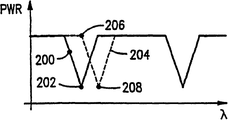
탐색 논리 회로(104)는 도 4에 점(200)으로 도시된 바와 같은, 신호 파워의 감쇄부에 대해 라인(74)상의 피드백 신호를 모니터링한다. 파워의 감쇠부가 탐색 논리 회로(104)에 의해 감지되면, 탐색 논리 회로(104)는 라인(120)을 통해 스위치(100, 134)에 신호를 제공하여 탐색 모드로부터 추적 모드로 스위칭한다.The
추적 모드시에, 라인(74)상의 피드백 신호는 스위치(100)를 통해 라인(122)상으로 제공되어, 예를 들면, 연산 증폭기 및 트랜지스터와 같은 공지된 전자 부품을 포함하는 추적 논리 회로(124)에 공급된다. 이 추적 논리 회로(124)는 라인(126)을 통해 합산기(128)에 추적 신호를 제공한다. AC 소스(130)에 의해 발생된 AC 디떠링 신호(dither signal)가 라인(132)을 통해 스위치(134)에 제공되며, 또한 라인(135)를 통해 합산기(128)에 공급된다. 라인(132)상의 디떠링 신호는 사전결정된 고정 진폭 및 주파수(이후 설명됨)를 갖는 AC 신호이다. 이 디떠링 신호는 추적 논리 회로(124)를 동작시킬 수 있는 진폭 변조(이후 설명됨)로서 기능한다.In tracking mode, a feedback signal on
추적 논리 회로(124)는 라인(122)상의 피드백 신호의 디떠링 성분을 모니터링하여 라인(40)상의 튜너 신호를 도 4에 점(202)으로 도시된 바와 같은 파워 곡선의 국부적 최소 피크와 연관된 파장으로 구동한다. 이것은 라인(122)상의 피드백 신호를 모니터하고 기준 신호로서 라인(132)상의 디떠링 신호를 이용하여 디떠링 주파수를 고정시키므로써 성취된다. 추적 논리 회로(124)는 피드백 신호의 디떠링 성분의 크기 및 위상을 판정한다. 시스템이 점(202) 주위에서 디떠링하고 있을 때 이 디떠링 성분의 크기는 센서 스펙트럼의 형상으로 인해 제로(또는 매우 작음)이다. 특히, 이 디떠링 주파수 성분은 최소 점에서 센서 형상의 대칭성으로 인해 배가된다. 정적 스트레인이 새로운 값으로 변화하면, 이로 인해 곡선(204)으로 표시된 바와 같이 스펙트럼(또는 프로화일)이 쉬프트하고 동작 점도 점(206)으로 쉬프트한다. 이 점에서, 피드백 신호의 디떠링 성분과 라인(132)상의 디떠링 기준 신호간의 위상차의 부호는 튜너(36)(도 1 참조)를 구동하기 위한 추적 논리 회로(124)의 방향이 점(208)(곡선(204)의 국부적 최소 지점)의 파장을 향하고 있음을 표시한다. 이 때 추적 논리 회로는 튜너(36)를 점(208)으로 구동하며, 이 경우 디떠링 주파수에서의 크기는 또한 제로가 된다.The tracking
따라서, 추적 논리 회로(124)는 고정 증폭기(a lock-in amplifier)로서 동작하여, 정적 스트레인 변동과 연관된 센서 응답 특성의 DC 변화를 추적한다. 소망하는 동작 점에 대해 고정 증폭기로서 동작한다면 어떤 다른 제어장치 구성도 이용될 수 있다.Accordingly, the tracking
이제 도 5를 참조하여 설명하면, 파형(220)으로 도시된 바와 같은, 예를 들면, 50㎐의 저 주파수와, 예를 들면, 0.05㎚에 대응하는 약 50마이크로스트레인의 진폭을 갖는 동적(또는 AC) 스트레인이 시스템에 인가되고 정적 스트레인은 고정된 경우(설명을 용이하게 하기 위해 가정함), 센서 프로화일은 동작 점 주위에서 발진하며, 이것은 도면중에서 화살표(222)로 도시된 바와 같이 센서 프로화일 양측면 주위에서 발진하는 동작 점으로서 관측될 수 있다. 최상의 성능을 위해 동적 스트레인의 크기는 센서 프로화일의 최대-전체-진폭의-½(full-width-half-max), 예를 들면, 0.2㎚ 또는 200마이크로스트레인으로 제한되어야 하지만, 원한다면, 더욱 큰 스트레인이 이용될 수도 있다.Referring now to FIG. 5, a dynamic (or having a low frequency of, for example, 50 Hz, as shown by
결과적으로 얻어지는 출력 파형(224)은 센서 응답 함수의 형상으로 인해 동적 스트레인 주파수의 두 배 주파수를 갖는 엔벨롭(225)을 갖는다. 디떠링 신호는 파형(227) 및 센서 프로화일을 따른 점(226)에서 화살표(228)로 표시된다. 이 디떠링 신호는 파형(224)으로 도시된 바와 같은 동적 스트레인 신호의 대응하는 진폭 변조를 초래한다.The resulting
출력 신호(224)의 디떠링(또는 반송파) 성분의 주파수 및 진폭은 또한 센서 프로화일의 대칭 성질(이후 설명됨)로 인해 디떠링 주파수의 두 배의 주파수 성분을 갖는다. 이 디떠링 신호 및 동적 스트레인 신호의 진폭은 출력 파형(224)의 형상에 영향을 주게 된다. 또한, 시스템이 최소 전달 점상에서 폐쇄-루프로 동작중인지의 여부도 출력 파형(224)의 형상에 영향을 미친다.The frequency and amplitude of the dethering (or carrier) component of the
신호를 디떠링시키는 목적은 신뢰성있는 AC 신호를 제공하여, 정적 DC 스트레인에 변화가 발생한 때, 심지어 어떤 AC 동적 스트레인도 존재하지 않는 때에도 추적 논리 회로(124)가 센서 프로화일에 있어서의 놋치(notch)를 추적할 수 있게 하는 것이다. 또한, 디떠링 진폭은 시스템내의 노이즈 레벨보다 훨씬 더 커서 적절한 추적이 이루어질 수 있게 해야 하고, 대표적으로 스트레인 신호 진폭 정도이다. 더욱이, 디떠링 주파수는, 예로서, 1㎑ 로서, 또한 추적 논리 회로(124)의 제어 응답보다 크고 측정되는 동적 AC 신호보다 더 크게 세트되어야 한다.The purpose of deranging the signal is to provide a reliable AC signal so that when the change in the static DC strain occurs, the tracking
다시 도 1을 참조하면, 시스템이 폐쇄-루프(CL) 모드로 동작할 때, 라인(74)상의 피드백 신호는 디떠링 주파수로 동작하는 복조기(76)에 공급되며, 복조기는 공지된 방법으로 피드백 신호를 복조하여 디떠링(또는 복조) 신호에 의해 야기된 진폭 변조를 제거하여, 라인(78)을 통해 동적 스트레인에 관련된 진폭 및 동적 스트레인 주파수의 두 배의 주파수를 갖는 복조된 AC 신호를 신호 처리 회로(80)에 제공한다. 예를 들어, 복조기(76)는 디떠링 주파수에 중심을 두고 변조 측파대를 통과시키는 대역통과 필터, 전파 정류기 및 저역 필터를 포함할 수도 있다.Referring back to FIG. 1, when the system is operating in closed-loop (CL) mode, the feedback signal on
신호 처리 회로(80)는 라인(78)상의 복조된 신호의 주파수 및 진폭을 검출하여 라인(86)상으로 동적 스트레인 신호를 제공한다. 이 동적 스트레인은 ½의 주파수와 이 동적 스트레인의 크기에 직접 비례하는 진폭을 획득하므로써 계산된다.
또한, 신호 처리 회로(80)는 라인(40)상의 튜너 구동 신호를 모니터링하여 어느 센서가 분석되고 있는지를 판정하며, 이것은 전압이 광원(44)의 도파관에 비례하고 각 센서의 도파관 범위는 공지되기 때문이다. 추적 모드에서 튜너 제어 신호에 대한 디떠링은 그의 작은 진폭으로 인해 최소의 효과를 갖는다.The
대안적으로, 신호 처리 회로(80)는 튜너 제어 회로(42)로 부터의 라인(90)상의 동기 신호를 모니터링하여 주어진 시간에 어느 센서가 분석되고 있는지를 판정하기 위한 동기를 제공한다. 예를 들면, 라인(120)상의 스위칭 신호는 탐색 논리 회로(104)가 탐색 모드로부터 추적 모드로 스위치될 때 다음 센서를 발견하였음을 표시하기 때문에 동기 신호로서 이용될 수도 있다.Alternatively, the
다시 도 3을 참조하면, 추적 논리 회로가 사전결정된 시간, 예를 들어, 100㎳동안 센서 프로화일의 놋치를 추적했을 때, 탐색 논리 회로(104)는 다시 튜너 구동 신호의 제어를 획득하며 스위치(100, 134)를 "탐색" 위치로 스위칭하므로써 튜너 구동 신호로 부터의 디떠링 신호를 디스에이블시켜 탐색 논리 회로(104)가 앞서 언급된 바와 같이 피드백 신호내에서 감쇠부로 표시되는 격자 센서 프로화일내의 다음 놋치를 탐색할 수 있게 한다. 또한, 라인(126)상의 추적 논리 제어 신호는 추적을 중지한 위치로 유지되며, 탐색 논리 회로(104)는 이 위치로부터 증가하기 시작하여 다음 격자 센서와 연관된 놋치로의 유연한 변이를 보장한다.Referring again to FIG. 3, when the tracking logic circuit tracks the notch of the sensor profile for a predetermined time, for example 100 ms, the
복조기(76)는 스위치(72)의 입력단에 위치되어 항상 라인(66)상의 피드백 신호를 복조할 수도 있음을 이해해야 한다. 이 경우, 디떠링 신호는 탐색 모드시의 회로로부터 스위치될 필요는 없다. 그러나 라인(40)상의 튜너 제어 신호가 신호 처리 회로(80, 84)에 의해 이용된 경우 추가의 복조기가 필요할 수도 있다.It should be understood that
도 1을 다시 참조하면, 시스템은 훼브리-페로트형 결합 공동 구성(a Febry-Perot type coupled cavity configuration)으로 구성될 수도 있다. 이러한 구성에서는, 광 스위치(46, 50)가 상태2에 위치되어 광(44)의 광 경로로부터 광 분리기가제거된다. 이 경우, 광섬유(240)는 두 스위치(46, 50)를 접속하며, 격자 센서(54)는 격자(34)와 레이저 다이오드의 후면(12)과 함께 결합 공동으로서 동작한다.Referring back to FIG. 1, the system may be configured in a Febry-Perot type coupled cavity configuration. In this configuration,
당 분야에 발진 주파수가 제 2 공동 미러(54)와 제 1 공동 미러(34)간의 거리에 관련되는 결합 공동이 공지되어 있다. 특히, 센서(54)는 이 공동 미러(34)로부터 사전결정된 거리에 위치되므로, 결합 공동은 사전결정된 주파수에서 공진하게 된다.It is known in the art for a coupling cavity in which the oscillation frequency is related to the distance between the
스트레인이 센서(54)에 인가되고 그의 피크 반사 파장이 쉬프트함에 따라 사전결정된 공진 주파수에서의 반사량은 감소하여 공동을 "튜닝해제(detuning)"시킨다. 이에 의해 인가된 스트레인의 함수로서 강도에 심각한 로울오프(rolloff)가 발생하여 극히 민감한 검출기가 얻어진다. 마찬가지의 결합 공동 효과가 격자(58) 및 광섬유(52)상의 어떤 다른 격자에 대해서도 발생한다. 따라서, 훼브리-페로트 구성은 동적 스트레인을 검출하는 매우 고감도의 구성을 제공한다.As strain is applied to the
또한, 훼브리-페로트 구성은 센서를 포함할 수도 포함하지 않을 수도 있는 보다 길거나 짧은 길이의 광섬유를 포함하도록 이용될 수도 있음을 이해해야 한다. 예를 들어, 센서가 구조물(62)을 따라 최외측 센서인 경우, 광섬유의 전체 길이를 포함하는 결합 공동을, 따라서, 구조물(62)의 전체 길이를 한정하게 된다. 따라서, 구조물을 따라 어딘가에서 스트레인이 발생한 경우, 이 긴 결합-공동을 튜닝해제시키게 되고, 따라서, 광섬유를 따라 어딘가에서 스트레인이 발생되었음을 표시한다.In addition, it is to be understood that the Fabry-Perot configuration may be used to include longer or shorter length optical fibers that may or may not include sensors. For example, if the sensor is the outermost sensor along the
일단 광섬유를 따라 어딘가에서 스트레인이 발생하였음을 판정하면, 시스템은 광섬유의 길이를 따라 더욱 구체적인 질의를 수행하여 스트레인이 발생한 위치를 정확히 판정할 수 있다. 구조물을 따라 어디에서 스트레인이 발생했는지를 판정하기 위해, 구조물의 반대측 단부에 더 가까운 위치에 위치된 센서가 연속적으로 조사되어 그들이 또한 튜닝 해제되었는지의 여부를 알 수 있다. 튜닝 해제되지 않은 센서 공동에 도달하면, 스트레인은 그 센서와 다음의 인접하는 센서 사이에서 발생한 것이다. 이와 달리, 시스템은 스위치(46, 50)를 상태1에 위치시키므로써 직접 전달(또는 반사) 모드로 스위치할 수도 있고 앞서 설명된 바와 같이 각 센서를 개별적으로 질의할 수도 있다.Once it is determined that strain has occurred somewhere along the fiber, the system can perform a more specific query along the length of the fiber to accurately determine where the strain occurred. In order to determine where strain occurred along the structure, sensors located at locations closer to the opposite end of the structure may be continuously illuminated to see if they are also untuned. Upon reaching the untuned sensor cavity, strain is generated between the sensor and the next adjacent sensor. Alternatively, the system may switch to direct delivery (or reflection) mode by placing
훼브리-페로트 구성은 폐쇄-루프 구성으로 이용되며, 따라서, 앞서 설명된 도 3의 동일한 추적 및 탐색 구성을 이용할 수도 있다. 훼브리-페로트 감지 기법은 또한 개방-루프 동작 모드로 수행될 수도 있지만, 격자가 범위밖으로 벗어나는 경우 감도를 현저히 상실한다.The Fabry-Perot configuration is used in a closed-loop configuration, and thus may use the same tracking and searching configuration of FIG. 3 described above. Fabry-Perot sensing techniques may also be performed in an open-loop operating mode, but significantly lose sensitivity if the grating is out of range.
이제 도 6을 참조하면, 대안적으로, 본 발명은 전달 모드 대신에 반사 모드로 구성될 수도 있다. 이 경우, 구성은 본질적으로 도 1을 참조하여 앞서 설명한 것과 동일하지만, 광 스위치(50)와 구조물(62) 사이에 2X2 결합기(250)가 제공된다. 앞서 설명된 바와 같이, 센서(54)는 라인(56)으로 도시한 바와 같이 협파장 대역 광(55)을 반사하고 나머지 파장의 광을 통과시킨다. 나머지 광(56)은 센서(58)로 입사하여 협파장 대역 광(59)을 반사하고 나머지 광(60)을 통과시킨다. 피반사 광(55, 59)은 결합기(250)내로 되반사되어 포트(256)로부터 광섬유(258)를 따라 광 검출기(64)로 방출된다. 이 검출기(64)는 라인(66)상으로 도 1을 참조하여 앞서 설명된 피전달 파워에 반대되는 피반사 파워를 표시하는 전기적 신호를 제공한다.Referring now to FIG. 6, alternatively, the present invention may be configured in a reflective mode instead of a delivery mode. In this case, the configuration is essentially the same as described above with reference to FIG. 1, but a 2 × 2
도 6의 반사 모드 구성과 도 1의 전달 모드 구성간의 유일한 실질적인 차이는 도 2c, 4 및 5의 센서 프로화일에 대해 출력 파워가 일정한 고레벨이고 감쇠 놋치를 갖는 대신에 파워가 일정한 저레벨이고 증가 놋치를 갖는다는 것이다. 모든 다른 효과는 본질적으로 동일하며 앞서의 설명으로부터 용이하게 추정해낼 수 있다. 또한, 훼브리-페로트 모드와 관련하여, 반사 모드로 이용된 경우, 공동에 대한 결합기의 광학적 효과가 고려되어야 하며 결합기로부터 공동으로 되돌아가는 어떤 반사 손실도 존재하지 않아야 한다.The only substantial difference between the reflection mode configuration of FIG. 6 and the delivery mode configuration of FIG. 1 is that for the sensor profiles of FIGS. 2C, 4 and 5, the output power is constant low level and has increased notches instead of having a constant high level and attenuation notch. Will be. All other effects are essentially the same and can be easily estimated from the foregoing description. In addition, with respect to the Fabry-Perot mode, when used in the reflection mode, the optical effect of the coupler on the cavity must be considered and there should be no reflection loss back from the coupler to the cavity.
광섬유(52)가 단지 한 단부에서 액세스될 수 있는 경우, 도 6에 도시된 구성이 최선 실시예이지만, 광섬유의 양 단부가 이용가능하고 액세스 가능한 경우는 도 1 또는 도 6의 어느 구성도 동일하게 허용가능하다.If the
또한, 본 발명이 스트레인을 검출하는데 이용된 것으로서 설명되었지만, 앞서 언급된 멜츠 등의 미국 특허 제 4,806,012 호 및 4,761,073 호에 설명된 바와 같이 반사(또는 전달) 프로화일에 변화를 초래하는 거라면 어떤 요인도 측정될 수 있다. 예를 들어, 광섬유는 전계 또는 자계 또는 어떤 화학적 혼합물 또는 다른 요인에 대한 노출로 인해 팽창 또는 수축하는 재료로 코팅될 수도 있다.In addition, although the present invention has been described as being used to detect strains, any factors may result in a change in the reflection (or transfer) profile as described in Melts et al. US Pat. Nos. 4,806,012 and 4,761,073. Can be measured. For example, the optical fiber may be coated with a material that expands or contracts due to exposure to an electric or magnetic field or some chemical mixture or other factor.
이상 본 발명이 요인을 검출하는 센서로서 브래그 격자를 이용하는 것으로서 설명되었지만, 원한다면, 인가된 스트레스에 의해 쉬프트하는 협파장 대역 반사를 갖는 어떤 반사 장치도 이용될 수 있다. 또한, 센서는 센서들을 지원하는 광섬유와 동일한 형태의 광섬유로 이용될 필요는 없으며, 예를 들어, 센서를 광섬유로 꼬여질 수도 있다.Although the present invention has been described as using a Bragg grating as a sensor for detecting factors, any reflecting device with narrow wavelength band reflection shifting by applied stress can be used if desired. In addition, the sensor need not be used as the optical fiber of the same type as the optical fiber supporting the sensors, for example, the sensor may be twisted into the optical fiber.
또한, 이상 본 발명이 광섬유를 이용하는 것으로서 설명되었지만, 원한다면, 어떤 다른 형태의 광 도파관도 이용될 수 있다. 또한, 전기 스위치(72)(도 1 참조), (98)(도 3 참조)는 조작자 또는 운전자로 부터의 명령에 응답하여 수동으로 제어되거나 마이크로프로세서 또는 CPU와 같은 (미도시된) 다른 신호 처리기에 의해 제어될 수도 있고, 또는 사전결정된 속도 또는 사전결정된 논리 조건하에서 스위치되어 정적 스트레인, 동적 스트레인을 판정하고 또는 전체 광섬유에 대한 스트레인 분석을 수행(훼브리-페로트 모드시에)할 수도 있다.In addition, while the present invention has been described as using an optical fiber, any other type of optical waveguide may be used if desired. Also, electrical switches 72 (see FIG. 1), 98 (see FIG. 3) may be manually controlled in response to commands from an operator or operator or other signal processor (not shown) such as a microprocessor or CPU. It may be controlled by or may be switched under a predetermined speed or predetermined logic conditions to determine static strain, dynamic strain, or perform strain analysis for the entire optical fiber (in Fabry-Perot mode).
또한, 튜너 제어 회로(42) 및 신호 처리 회로(68)는 적절한 하드웨어 인터페이스, 예를 들면, A/D 변환기를 이용하여 소프트웨어적으로 수행될 수도 있다.The
Claims (31)
Applications Claiming Priority (2)
| Application Number | Priority Date | Filing Date | Title |
|---|---|---|---|
| US08/129,217 US5401956A (en) | 1993-09-29 | 1993-09-29 | Diagnostic system for fiber grating sensors |
| PCT/US1994/013628 WO1996017224A1 (en) | 1993-09-29 | 1994-11-28 | Diagnostic system for fiber grating sensors |
Publications (1)
| Publication Number | Publication Date |
|---|---|
| KR100312902B1 true KR100312902B1 (en) | 2002-01-17 |
Family
ID=22438940
Family Applications (1)
| Application Number | Title | Priority Date | Filing Date |
|---|---|---|---|
| KR1019970703535A KR100312902B1 (en) | 1993-09-29 | 1994-11-28 | Diagnostic system for fiber grating sensors |
Country Status (9)
| Country | Link |
|---|---|
| US (1) | US5401956A (en) |
| EP (1) | EP0803049B1 (en) |
| KR (1) | KR100312902B1 (en) |
| CA (1) | CA2203537C (en) |
| DE (1) | DE69414011T2 (en) |
| DK (1) | DK0803049T3 (en) |
| RU (1) | RU2141102C1 (en) |
| TW (1) | TW256876B (en) |
| WO (1) | WO1996017224A1 (en) |
Cited By (1)
| Publication number | Priority date | Publication date | Assignee | Title |
|---|---|---|---|---|
| KR101780898B1 (en) * | 2015-08-24 | 2017-09-21 | 김영태 | Vibration measuring apparatus |
Families Citing this family (123)
| Publication number | Priority date | Publication date | Assignee | Title |
|---|---|---|---|---|
| US5513913A (en) * | 1993-01-29 | 1996-05-07 | United Technologies Corporation | Active multipoint fiber laser sensor |
| JP3410101B2 (en) * | 1994-11-29 | 2003-05-26 | ユナイテッド テクノロジーズ コーポレイション | Coating annihilation detection by optical fiber Bragg grating |
| US5493113A (en) * | 1994-11-29 | 1996-02-20 | United Technologies Corporation | Highly sensitive optical fiber cavity coating removal detection |
| US5640472A (en) * | 1995-06-07 | 1997-06-17 | United Technologies Corporation | Fiber optic sensor for magnetic bearings |
| US5748312A (en) * | 1995-09-19 | 1998-05-05 | United States Of American As Represented By The Secretary Of The Navy | Sensing apparatus and method for detecting strain between fiber bragg grating sensors inscribed into an optical fiber |
| US5770155A (en) * | 1995-11-21 | 1998-06-23 | United Technologies Corporation | Composite structure resin cure monitoring apparatus using an optical fiber grating sensor |
| US6111681A (en) | 1996-02-23 | 2000-08-29 | Ciena Corporation | WDM optical communication systems with wavelength-stabilized optical selectors |
| US5945666A (en) * | 1996-05-20 | 1999-08-31 | The United States Of America As Represented By The Secretary Of The Navy | Hybrid fiber bragg grating/long period fiber grating sensor for strain/temperature discrimination |
| US5706375A (en) * | 1996-09-10 | 1998-01-06 | Jds Fitel Inc. | Variable-attenuation tunable optical router |
| US5892582A (en) * | 1996-10-18 | 1999-04-06 | Micron Optics, Inc. | Fabry Perot/fiber Bragg grating multi-wavelength reference |
| US5838437A (en) * | 1997-04-09 | 1998-11-17 | Micron Optics, Inc. | Reference system for optical devices including optical scanners and spectrum analyzers |
| US5767411A (en) * | 1996-12-31 | 1998-06-16 | Cidra Corporation | Apparatus for enhancing strain in intrinsic fiber optic sensors and packaging same for harsh environments |
| US5892860A (en) * | 1997-01-21 | 1999-04-06 | Cidra Corporation | Multi-parameter fiber optic sensor for use in harsh environments |
| US6072567A (en) * | 1997-02-12 | 2000-06-06 | Cidra Corporation | Vertical seismic profiling system having vertical seismic profiling optical signal processing equipment and fiber Bragg grafting optical sensors |
| NO307357B1 (en) * | 1997-02-14 | 2000-03-20 | Optoplan As | Device for painting optical wavelengths |
| US5818585A (en) * | 1997-02-28 | 1998-10-06 | The United States Of America As Represented By The Secretary Of The Navy | Fiber Bragg grating interrogation system with adaptive calibration |
| US5945665A (en) * | 1997-05-09 | 1999-08-31 | Cidra Corporation | Bolt, stud or fastener having an embedded fiber optic Bragg Grating sensor for sensing tensioning strain |
| US5925879A (en) * | 1997-05-09 | 1999-07-20 | Cidra Corporation | Oil and gas well packer having fiber optic Bragg Grating sensors for downhole insitu inflation monitoring |
| US5973317A (en) * | 1997-05-09 | 1999-10-26 | Cidra Corporation | Washer having fiber optic Bragg Grating sensors for sensing a shoulder load between components in a drill string |
| US6016702A (en) * | 1997-09-08 | 2000-01-25 | Cidra Corporation | High sensitivity fiber optic pressure sensor for use in harsh environments |
| US6175108B1 (en) | 1998-01-30 | 2001-01-16 | Cidra Corporation | Accelerometer featuring fiber optic bragg grating sensor for providing multiplexed multi-axis acceleration sensing |
| US6191414B1 (en) | 1998-06-05 | 2001-02-20 | Cidra Corporation | Composite form as a component for a pressure transducer |
| RU2250438C9 (en) | 1998-06-26 | 2005-08-27 | Сидрэ Копэрейшн | Method and device for measuring parameters of fluids in pipes |
| US6522797B1 (en) | 1998-09-01 | 2003-02-18 | Input/Output, Inc. | Seismic optical acoustic recursive sensor system |
| DE19856549A1 (en) * | 1998-12-08 | 2000-06-15 | Daimler Chrysler Ag | Measuring arrangement for the control and evaluation of fiber grid networks |
| US6233374B1 (en) | 1999-06-04 | 2001-05-15 | Cidra Corporation | Mandrel-wound fiber optic pressure sensor |
| US6463813B1 (en) | 1999-06-25 | 2002-10-15 | Weatherford/Lamb, Inc. | Displacement based pressure sensor measuring unsteady pressure in a pipe |
| US6536291B1 (en) | 1999-07-02 | 2003-03-25 | Weatherford/Lamb, Inc. | Optical flow rate measurement using unsteady pressures |
| US6691584B2 (en) | 1999-07-02 | 2004-02-17 | Weatherford/Lamb, Inc. | Flow rate measurement using unsteady pressures |
| US6274863B1 (en) | 1999-07-23 | 2001-08-14 | Cidra Corporation | Selective aperture arrays for seismic monitoring |
| US6601458B1 (en) | 2000-03-07 | 2003-08-05 | Weatherford/Lamb, Inc. | Distributed sound speed measurements for multiphase flow measurement |
| US6813962B2 (en) * | 2000-03-07 | 2004-11-09 | Weatherford/Lamb, Inc. | Distributed sound speed measurements for multiphase flow measurement |
| DE10014175C2 (en) | 2000-03-23 | 2002-12-12 | Daimler Chrysler Ag | Arrangement of several fiber-optic Bragg grating sensors and method for determining measured values in one |
| DE50102349D1 (en) * | 2000-03-23 | 2004-06-24 | Eupec Gmbh & Co Kg | ARRANGEMENT OF ELECTRONIC COMPONENTS WITH TEMPERATURE SENSOR |
| US6351987B1 (en) | 2000-04-13 | 2002-03-05 | Cidra Corporation | Fiber optic pressure sensor for DC pressure and temperature |
| US6601671B1 (en) | 2000-07-10 | 2003-08-05 | Weatherford/Lamb, Inc. | Method and apparatus for seismically surveying an earth formation in relation to a borehole |
| AU2001288310A1 (en) * | 2000-08-18 | 2002-03-04 | The Government Of The United States Of America, As Represented By The Secretary Of The Navy | A method and apparatus for transverse load sensing by use of pi-phase shifted optical fiber |
| US6714565B1 (en) * | 2000-11-01 | 2004-03-30 | Agilent Technologies, Inc. | Optically tunable Fabry Perot microelectromechanical resonator |
| US6747743B2 (en) | 2000-11-10 | 2004-06-08 | Halliburton Energy Services, Inc. | Multi-parameter interferometric fiber optic sensor |
| AU1595301A (en) * | 2000-11-10 | 2002-05-21 | Halliburton Energy Serv Inc | Multi-parameter interferometric fiber optic sensor |
| US6785004B2 (en) * | 2000-11-29 | 2004-08-31 | Weatherford/Lamb, Inc. | Method and apparatus for interrogating fiber optic sensors |
| US6782150B2 (en) * | 2000-11-29 | 2004-08-24 | Weatherford/Lamb, Inc. | Apparatus for sensing fluid in a pipe |
| US6619864B2 (en) | 2001-03-15 | 2003-09-16 | Optinel Systems, Inc. | Optical channel monitor with continuous gas cell calibration |
| US6959153B2 (en) * | 2001-05-24 | 2005-10-25 | Broadband Royalty Corporation | Dynamically reconfigurable add/drop multiplexer with low coherent cross-talk for optical communication networks |
| US6993257B2 (en) * | 2001-08-15 | 2006-01-31 | Broadband Royalty Corporation | Optical channel monitor utilizing multiple Fabry-Perot filter pass-bands |
| US6724786B2 (en) * | 2001-08-31 | 2004-04-20 | International Business Machines Corporation | Variable optical attenuator using wavelength locked loop tuning |
| DE10145350B4 (en) * | 2001-09-14 | 2006-03-30 | Airbus Deutschland Gmbh | Increasing the resolution of Bragg sensor measurement systems |
| US6549687B1 (en) * | 2001-10-26 | 2003-04-15 | Lake Shore Cryotronics, Inc. | System and method for measuring physical, chemical and biological stimuli using vertical cavity surface emitting lasers with integrated tuner |
| US6698297B2 (en) | 2002-06-28 | 2004-03-02 | Weatherford/Lamb, Inc. | Venturi augmented flow meter |
| US6971259B2 (en) * | 2001-11-07 | 2005-12-06 | Weatherford/Lamb, Inc. | Fluid density measurement in pipes using acoustic pressures |
| US7059172B2 (en) * | 2001-11-07 | 2006-06-13 | Weatherford/Lamb, Inc. | Phase flow measurement in pipes using a density meter |
| US6738536B2 (en) * | 2001-12-20 | 2004-05-18 | Optinel Systems, Inc. | Wavelength tunable filter device for fiber optic systems |
| US6724962B2 (en) * | 2002-01-23 | 2004-04-20 | Yuan Ze University | Wavelength to optical power converter and method for converting wavelength into optical power |
| DE10210787B4 (en) * | 2002-03-12 | 2005-02-03 | Daimlerchrysler Ag | Apparatus and method for measuring deformation and sound waves in solids |
| NO316547B1 (en) * | 2002-06-17 | 2004-02-02 | Light Structures As | Analyzer for fiber sensors |
| US20030234921A1 (en) | 2002-06-21 | 2003-12-25 | Tsutomu Yamate | Method for measuring and calibrating measurements using optical fiber distributed sensor |
| AU2003255235A1 (en) * | 2002-08-08 | 2004-02-25 | Cidra Corporation | Apparatus and method for measuring multi-phase flows in pulp and paper industry applications |
| US6888972B2 (en) * | 2002-10-06 | 2005-05-03 | Weatherford/Lamb, Inc. | Multiple component sensor mechanism |
| US7036601B2 (en) | 2002-10-06 | 2006-05-02 | Weatherford/Lamb, Inc. | Apparatus and method for transporting, deploying, and retrieving arrays having nodes interconnected by sections of cable |
| US20040065437A1 (en) * | 2002-10-06 | 2004-04-08 | Weatherford/Lamb Inc. | In-well seismic sensor casing coupling using natural forces in wells |
| CA2444379C (en) | 2002-10-06 | 2007-08-07 | Weatherford/Lamb, Inc. | Multiple component sensor mechanism |
| WO2004036700A2 (en) * | 2002-10-15 | 2004-04-29 | Micron Optics, Inc. | Waferless fiber fabry-perot filters |
| EP1583989A4 (en) * | 2002-12-20 | 2006-07-05 | Micron Optics Inc | Temperature compensated ferrule holder for a fiber fabry-perot filter |
| US7028543B2 (en) | 2003-01-21 | 2006-04-18 | Weatherford/Lamb, Inc. | System and method for monitoring performance of downhole equipment using fiber optic based sensors |
| US7119325B2 (en) * | 2003-01-27 | 2006-10-10 | Bookham Technology Plc | System and method for monitoring environmental effects using optical sensors |
| US6986276B2 (en) * | 2003-03-07 | 2006-01-17 | Weatherford/Lamb, Inc. | Deployable mandrel for downhole measurements |
| US6837098B2 (en) | 2003-03-19 | 2005-01-04 | Weatherford/Lamb, Inc. | Sand monitoring within wells using acoustic arrays |
| US6836578B2 (en) * | 2003-04-14 | 2004-12-28 | Lake Shore Cryotronics, Inc. | System and method for measuring physical stimuli using vertical cavity surface emitting lasers with integrated tuning means |
| US6840114B2 (en) * | 2003-05-19 | 2005-01-11 | Weatherford/Lamb, Inc. | Housing on the exterior of a well casing for optical fiber sensors |
| US6957574B2 (en) * | 2003-05-19 | 2005-10-25 | Weatherford/Lamb, Inc. | Well integrity monitoring system |
| US20080264182A1 (en) * | 2003-08-22 | 2008-10-30 | Jones Richard T | Flow meter using sensitive differential pressure measurement |
| US6910388B2 (en) * | 2003-08-22 | 2005-06-28 | Weatherford/Lamb, Inc. | Flow meter using an expanded tube section and sensitive differential pressure measurement |
| KR100594961B1 (en) * | 2003-09-26 | 2006-06-30 | 한국전자통신연구원 | Apparatus and Method for Optical Communication using Subcarrier Muliple Access |
| GB2407377B (en) * | 2003-10-16 | 2006-04-19 | Kidde Ip Holdings Ltd | Fibre bragg grating sensors |
| US7305158B2 (en) * | 2004-04-15 | 2007-12-04 | Davidson Instruments Inc. | Interferometric signal conditioner for measurement of absolute static displacements and dynamic displacements of a Fabry-Perot interferometer |
| US7492463B2 (en) | 2004-04-15 | 2009-02-17 | Davidson Instruments Inc. | Method and apparatus for continuous readout of Fabry-Perot fiber optic sensor |
| US7480056B2 (en) * | 2004-06-04 | 2009-01-20 | Optoplan As | Multi-pulse heterodyne sub-carrier interrogation of interferometric sensors |
| US7109471B2 (en) * | 2004-06-04 | 2006-09-19 | Weatherford/Lamb, Inc. | Optical wavelength determination using multiple measurable features |
| BRPI0403268B1 (en) * | 2004-08-10 | 2017-07-18 | Petroleo Brasileiro S.A. - Petrobras | SYSTEM FOR READING AND DATA ACQUISITION FOR FIBER OPTICAL SENSORS |
| US7864329B2 (en) * | 2004-12-21 | 2011-01-04 | Halliburton Energy Services, Inc. | Fiber optic sensor system having circulators, Bragg gratings and couplers |
| US7835598B2 (en) * | 2004-12-21 | 2010-11-16 | Halliburton Energy Services, Inc. | Multi-channel array processor |
| US8122951B2 (en) * | 2005-02-28 | 2012-02-28 | Schlumberger Technology Corporation | Systems and methods of downhole thermal property measurement |
| EP1869737B1 (en) * | 2005-03-16 | 2021-05-12 | Davidson Instruments, Inc. | High intensity fabry-perot sensor |
| JP2008537358A (en) * | 2005-04-19 | 2008-09-11 | ブーカム テクノロジー ピーエルシー | Electronic wavelength marker system and method |
| US7282698B2 (en) * | 2005-09-08 | 2007-10-16 | Baker Hughes Incorporated | System and method for monitoring a well |
| WO2007033069A2 (en) * | 2005-09-13 | 2007-03-22 | Davidson Instruments Inc. | Tracking algorithm for linear array signal processor for fabry-perot cross-correlation pattern and method of using same |
| US7580323B2 (en) * | 2005-10-21 | 2009-08-25 | The United States Of America As Represented By The Administrator Of The National Aeronautics And Space Adninistration | Tunable optical assembly with vibration dampening |
| US7503217B2 (en) * | 2006-01-27 | 2009-03-17 | Weatherford/Lamb, Inc. | Sonar sand detection |
| US8989528B2 (en) | 2006-02-22 | 2015-03-24 | Hansen Medical, Inc. | Optical fiber grating sensors and methods of manufacture |
| US9186046B2 (en) | 2007-08-14 | 2015-11-17 | Koninklijke Philips Electronics N.V. | Robotic instrument systems and methods utilizing optical fiber sensor |
| EP1996063B1 (en) * | 2006-03-22 | 2019-07-03 | Koninklijke Philips N.V. | Fiber optic instrument sensing system |
| US7684051B2 (en) * | 2006-04-18 | 2010-03-23 | Halliburton Energy Services, Inc. | Fiber optic seismic sensor based on MEMS cantilever |
| US7743661B2 (en) * | 2006-04-26 | 2010-06-29 | Halliburton Energy Services, Inc. | Fiber optic MEMS seismic sensor with mass supported by hinged beams |
| US20070280605A1 (en) * | 2006-05-31 | 2007-12-06 | Mendoza Edgar A | Fiber bragg grating sensor interrogator and manufacture thereof |
| US8115937B2 (en) * | 2006-08-16 | 2012-02-14 | Davidson Instruments | Methods and apparatus for measuring multiple Fabry-Perot gaps |
| CA2661276C (en) * | 2006-08-16 | 2013-07-23 | Schlumberger Canada Limited | A fiber-optic transducer for fluid and/or gas velocity measurement |
| WO2008091645A1 (en) * | 2007-01-24 | 2008-07-31 | Davidson Energy | Transducer for measuring environmental parameters |
| US8146874B2 (en) * | 2007-02-02 | 2012-04-03 | Hansen Medical, Inc. | Mounting support assembly for suspending a medical instrument driver above an operating table |
| WO2008131303A2 (en) | 2007-04-20 | 2008-10-30 | Hansen Medical, Inc. | Optical fiber shape sensing systems |
| US20090059209A1 (en) * | 2007-09-05 | 2009-03-05 | An-Dien Nguyen | Lock-in demodulation technique for optical interrogation of a grating sensor |
| DE102009002708A1 (en) * | 2009-04-29 | 2010-11-04 | Robert Bosch Gmbh | Method for identifying sensors on a bus by a control unit, and a control unit and a sensor for this purpose |
| US8780339B2 (en) | 2009-07-15 | 2014-07-15 | Koninklijke Philips N.V. | Fiber shape sensing systems and methods |
| US20120191107A1 (en) | 2010-09-17 | 2012-07-26 | Tanner Neal A | Systems and methods for positioning an elongate member inside a body |
| US9557239B2 (en) | 2010-12-03 | 2017-01-31 | Baker Hughes Incorporated | Determination of strain components for different deformation modes using a filter |
| US9103736B2 (en) | 2010-12-03 | 2015-08-11 | Baker Hughes Incorporated | Modeling an interpretation of real time compaction modeling data from multi-section monitoring system |
| US9194973B2 (en) | 2010-12-03 | 2015-11-24 | Baker Hughes Incorporated | Self adaptive two dimensional filter for distributed sensing data |
| US20120191086A1 (en) | 2011-01-20 | 2012-07-26 | Hansen Medical, Inc. | System and method for endoluminal and translumenal therapy |
| US9138166B2 (en) | 2011-07-29 | 2015-09-22 | Hansen Medical, Inc. | Apparatus and methods for fiber integration and registration |
| CN102607618B (en) * | 2012-02-21 | 2014-12-10 | 南京航空航天大学 | Optical fiber sensing method, optical fiber sensing device and using method of optical fiber sensing device |
| CN102638305B (en) * | 2012-03-29 | 2014-10-15 | 南京航空航天大学 | Optical single-side band modulation based optical device measuring method and optical single-side band modulation based optical device measuring device |
| WO2014023770A2 (en) * | 2012-08-07 | 2014-02-13 | Faz Research Limited | System and method for dynamically sweeping a tunable laser |
| RU2516346C1 (en) * | 2012-12-11 | 2014-05-20 | Общество с ограниченной ответственностью "Т8" (ООО "Т8") | Apparatus for monitoring vibroacoustic characteristics of extended object |
| CA2916266C (en) * | 2013-08-09 | 2018-11-27 | Halliburton Energy Services, Inc. | Improved optical fiber feedthrough incorporating fiber bragg grating |
| US9410422B2 (en) | 2013-09-13 | 2016-08-09 | Chevron U.S.A. Inc. | Alternative gauging system for production well testing and related methods |
| US9605534B2 (en) | 2013-11-13 | 2017-03-28 | Baker Hughes Incorporated | Real-time flow injection monitoring using distributed Bragg grating |
| CN103837178B (en) * | 2013-11-29 | 2017-01-18 | 湖北工业大学 | System and method for demodulating fiber bragg gratings based on liquid crystal F-P cavity adjustable filter technology |
| DE102015223918B3 (en) * | 2015-12-01 | 2017-05-11 | Bauhaus-Universität Weimar | Monitoring a material fatigue critical design area |
| GB2556932A (en) * | 2016-11-28 | 2018-06-13 | Airbus Operations Ltd | A fibre-optic communication system, a communication apparatus for the same, and a vehicle |
| RU203603U1 (en) * | 2020-12-15 | 2021-04-14 | Федеральное государственное бюджетное образовательное учреждение высшего образования "Казанский национальный исследовательский технический университет им. А.Н. Туполева - КАИ" | FIBER OPTICAL PRESSURE MEASURING DEVICE |
| RU203379U1 (en) * | 2020-12-15 | 2021-04-01 | Федеральное государственное бюджетное образовательное учреждение высшего образования "Казанский национальный исследовательский технический университет им. А.Н. Туполева - КАИ" | Fiber Optic Pressure Monitoring Device |
| RU203788U1 (en) * | 2020-12-15 | 2021-04-21 | Федеральное государственное бюджетное образовательное учреждение высшего образования "Казанский национальный исследовательский технический университет им. А.Н. Туполева - КАИ" | FIBER OPTICAL PRESSURE MEASURING DEVICE |
| GB2603205A (en) * | 2021-02-02 | 2022-08-03 | Focus Sensors Ltd | Ground sensing utlising active sources |
| CN114623923B (en) * | 2021-12-21 | 2023-09-01 | 浙江运达风电股份有限公司 | Verification test system and method for low-frequency vibration sensor at tower top of wind turbine generator |
Family Cites Families (7)
| Publication number | Priority date | Publication date | Assignee | Title |
|---|---|---|---|---|
| GB2145237B (en) * | 1981-04-03 | 1986-03-19 | Chevron Res | Optical system |
| US4806012A (en) * | 1984-08-13 | 1989-02-21 | United Technologies Corporation | Distributed, spatially resolving optical fiber strain gauge |
| US4761073A (en) * | 1984-08-13 | 1988-08-02 | United Technologies Corporation | Distributed, spatially resolving optical fiber strain gauge |
| US4985624A (en) * | 1988-05-11 | 1991-01-15 | Simmonds Precision Products, Inc. | Optical grating sensor and method of monitoring with a multi-period grating |
| US4996419A (en) * | 1989-12-26 | 1991-02-26 | United Technologies Corporation | Distributed multiplexed optical fiber Bragg grating sensor arrangeement |
| JPH04274724A (en) * | 1991-03-02 | 1992-09-30 | Fujikura Ltd | Otdr apparatus |
| IT1262407B (en) * | 1993-09-06 | 1996-06-19 | Finmeccanica Spa | INSTRUMENTATION USING INTEGRATED OPTIC COMPONENTS FOR DIAGNOSTICS OF PARTS WITH FIBER OPTIC SENSORS INCLUDED OR FIXED ON THE SURFACE. |
-
1993
- 1993-09-29 US US08/129,217 patent/US5401956A/en not_active Expired - Lifetime
-
1994
- 1994-11-28 RU RU97111857A patent/RU2141102C1/en active
- 1994-11-28 EP EP95903162A patent/EP0803049B1/en not_active Expired - Lifetime
- 1994-11-28 DK DK95903162T patent/DK0803049T3/en active
- 1994-11-28 CA CA002203537A patent/CA2203537C/en not_active Expired - Lifetime
- 1994-11-28 DE DE69414011T patent/DE69414011T2/en not_active Expired - Lifetime
- 1994-11-28 WO PCT/US1994/013628 patent/WO1996017224A1/en active IP Right Grant
- 1994-11-28 KR KR1019970703535A patent/KR100312902B1/en not_active IP Right Cessation
- 1994-12-07 TW TW083111352A patent/TW256876B/zh not_active IP Right Cessation
Cited By (1)
| Publication number | Priority date | Publication date | Assignee | Title |
|---|---|---|---|---|
| KR101780898B1 (en) * | 2015-08-24 | 2017-09-21 | 김영태 | Vibration measuring apparatus |
Also Published As
| Publication number | Publication date |
|---|---|
| DE69414011D1 (en) | 1998-11-19 |
| WO1996017224A1 (en) | 1996-06-06 |
| DE69414011T2 (en) | 1999-03-25 |
| EP0803049A1 (en) | 1997-10-29 |
| EP0803049B1 (en) | 1998-10-14 |
| CA2203537A1 (en) | 1996-06-06 |
| DK0803049T3 (en) | 1999-06-23 |
| TW256876B (en) | 1995-09-11 |
| RU2141102C1 (en) | 1999-11-10 |
| US5401956A (en) | 1995-03-28 |
| CA2203537C (en) | 2005-07-26 |
Similar Documents
| Publication | Publication Date | Title |
|---|---|---|
| KR100312902B1 (en) | Diagnostic system for fiber grating sensors | |
| EP1617183B1 (en) | (fiber) optic sensor with proper modulation | |
| US5963034A (en) | Electro-optic electromagnetic field sensor system with optical bias adjustment | |
| KR940011933B1 (en) | Method and apparatus for sensing a measurand | |
| De Brabander et al. | Integrated optical ring resonator with micromechanical diaphragms for pressure sensing | |
| US4976507A (en) | Sagnac distributed sensor | |
| US4627728A (en) | Compensated Fabry Perot sensor | |
| US4898468A (en) | Sagnac distributed sensor | |
| NO340954B1 (en) | Device for interferometric sensing | |
| JPH0663727B2 (en) | Position detection device and method | |
| KR100217714B1 (en) | Optical temperature sensor system with laser diode | |
| US4674881A (en) | Open loop thin film laser gyro | |
| JP2000236135A (en) | Self-monitoring light source for optical communication using stable wavelength | |
| US5956356A (en) | Monitoring wavelength of laser devices | |
| JP3081253B2 (en) | Optical detector | |
| Ribeiro et al. | Low coherence fiber optic system for remote sensors illuminated by a 1.3 μm multimode laser diode | |
| JPH11295153A (en) | Wavelength detecting device | |
| JP2003208689A (en) | Remote optical measurement system | |
| US5864400A (en) | Method of and device for measuring return losses in optical fiber components | |
| GB2198531A (en) | Optical sensor system | |
| JP3403657B2 (en) | Method for measuring reflection center wavelength of fiber grating element using disk-type tunable filter and measuring apparatus using the method | |
| US6298185B1 (en) | Distributed fiber grating sensing systems using birefringence fiber interferometers for detecting wavelength shifts | |
| JPH0560781A (en) | Acceleration measuring apparatus | |
| Takahashi et al. | Temperature stabilization of fiber Bragg grating vibration sensor with automatic wavelength control | |
| JPH0875434A (en) | Surface form measuring device |
Legal Events
| Date | Code | Title | Description |
|---|---|---|---|
| A201 | Request for examination | ||
| E902 | Notification of reason for refusal | ||
| E701 | Decision to grant or registration of patent right | ||
| GRNT | Written decision to grant | ||
| FPAY | Annual fee payment |
Payment date: 20120924 Year of fee payment: 12 |
|
| FPAY | Annual fee payment |
Payment date: 20130926 Year of fee payment: 13 |
|
| FPAY | Annual fee payment |
Payment date: 20140923 Year of fee payment: 14 |
|
| EXPY | Expiration of term |