EP1869737B1 - High intensity fabry-perot sensor - Google Patents
High intensity fabry-perot sensor Download PDFInfo
- Publication number
- EP1869737B1 EP1869737B1 EP06738462.8A EP06738462A EP1869737B1 EP 1869737 B1 EP1869737 B1 EP 1869737B1 EP 06738462 A EP06738462 A EP 06738462A EP 1869737 B1 EP1869737 B1 EP 1869737B1
- Authority
- EP
- European Patent Office
- Prior art keywords
- lens
- sensor assembly
- reflective surface
- diaphragm
- optical fiber
- Prior art date
- Legal status (The legal status is an assumption and is not a legal conclusion. Google has not performed a legal analysis and makes no representation as to the accuracy of the status listed.)
- Expired - Lifetime
Links
Images


Classifications
-
- G—PHYSICS
- G02—OPTICS
- G02B—OPTICAL ELEMENTS, SYSTEMS OR APPARATUS
- G02B6/00—Light guides; Structural details of arrangements comprising light guides and other optical elements, e.g. couplings
- G02B6/24—Coupling light guides
- G02B6/26—Optical coupling means
- G02B6/32—Optical coupling means having lens focusing means positioned between opposed fibre ends
- G02B6/322—Optical coupling means having lens focusing means positioned between opposed fibre ends and having centering means being part of the lens for the self-positioning of the lightguide at the focal point, e.g. holes, wells, indents, nibs
-
- G—PHYSICS
- G01—MEASURING; TESTING
- G01B—MEASURING LENGTH, THICKNESS OR SIMILAR LINEAR DIMENSIONS; MEASURING ANGLES; MEASURING AREAS; MEASURING IRREGULARITIES OF SURFACES OR CONTOURS
- G01B9/00—Measuring instruments characterised by the use of optical techniques
- G01B9/02—Interferometers
- G01B9/02055—Reduction or prevention of errors; Testing; Calibration
- G01B9/02062—Active error reduction, i.e. varying with time
- G01B9/02067—Active error reduction, i.e. varying with time by electronic control systems, i.e. using feedback acting on optics or light
- G01B9/02068—Auto-alignment of optical elements
-
- G—PHYSICS
- G01—MEASURING; TESTING
- G01D—MEASURING NOT SPECIALLY ADAPTED FOR A SPECIFIC VARIABLE; ARRANGEMENTS FOR MEASURING TWO OR MORE VARIABLES NOT COVERED IN A SINGLE OTHER SUBCLASS; TARIFF METERING APPARATUS; MEASURING OR TESTING NOT OTHERWISE PROVIDED FOR
- G01D5/00—Mechanical means for transferring the output of a sensing member; Means for converting the output of a sensing member to another variable where the form or nature of the sensing member does not constrain the means for converting; Transducers not specially adapted for a specific variable
- G01D5/26—Mechanical means for transferring the output of a sensing member; Means for converting the output of a sensing member to another variable where the form or nature of the sensing member does not constrain the means for converting; Transducers not specially adapted for a specific variable characterised by optical transfer means, i.e. using infrared, visible, or ultraviolet light
- G01D5/268—Mechanical means for transferring the output of a sensing member; Means for converting the output of a sensing member to another variable where the form or nature of the sensing member does not constrain the means for converting; Transducers not specially adapted for a specific variable characterised by optical transfer means, i.e. using infrared, visible, or ultraviolet light using optical fibres
-
- G—PHYSICS
- G01—MEASURING; TESTING
- G01D—MEASURING NOT SPECIALLY ADAPTED FOR A SPECIFIC VARIABLE; ARRANGEMENTS FOR MEASURING TWO OR MORE VARIABLES NOT COVERED IN A SINGLE OTHER SUBCLASS; TARIFF METERING APPARATUS; MEASURING OR TESTING NOT OTHERWISE PROVIDED FOR
- G01D5/00—Mechanical means for transferring the output of a sensing member; Means for converting the output of a sensing member to another variable where the form or nature of the sensing member does not constrain the means for converting; Transducers not specially adapted for a specific variable
- G01D5/26—Mechanical means for transferring the output of a sensing member; Means for converting the output of a sensing member to another variable where the form or nature of the sensing member does not constrain the means for converting; Transducers not specially adapted for a specific variable characterised by optical transfer means, i.e. using infrared, visible, or ultraviolet light
- G01D5/32—Mechanical means for transferring the output of a sensing member; Means for converting the output of a sensing member to another variable where the form or nature of the sensing member does not constrain the means for converting; Transducers not specially adapted for a specific variable characterised by optical transfer means, i.e. using infrared, visible, or ultraviolet light with attenuation or whole or partial obturation of beams of light
- G01D5/34—Mechanical means for transferring the output of a sensing member; Means for converting the output of a sensing member to another variable where the form or nature of the sensing member does not constrain the means for converting; Transducers not specially adapted for a specific variable characterised by optical transfer means, i.e. using infrared, visible, or ultraviolet light with attenuation or whole or partial obturation of beams of light the beams of light being detected by photocells
- G01D5/353—Mechanical means for transferring the output of a sensing member; Means for converting the output of a sensing member to another variable where the form or nature of the sensing member does not constrain the means for converting; Transducers not specially adapted for a specific variable characterised by optical transfer means, i.e. using infrared, visible, or ultraviolet light with attenuation or whole or partial obturation of beams of light the beams of light being detected by photocells influencing the transmission properties of an optical fibre
- G01D5/35306—Mechanical means for transferring the output of a sensing member; Means for converting the output of a sensing member to another variable where the form or nature of the sensing member does not constrain the means for converting; Transducers not specially adapted for a specific variable characterised by optical transfer means, i.e. using infrared, visible, or ultraviolet light with attenuation or whole or partial obturation of beams of light the beams of light being detected by photocells influencing the transmission properties of an optical fibre using an interferometer arrangement
- G01D5/35309—Mechanical means for transferring the output of a sensing member; Means for converting the output of a sensing member to another variable where the form or nature of the sensing member does not constrain the means for converting; Transducers not specially adapted for a specific variable characterised by optical transfer means, i.e. using infrared, visible, or ultraviolet light with attenuation or whole or partial obturation of beams of light the beams of light being detected by photocells influencing the transmission properties of an optical fibre using an interferometer arrangement using multiple waves interferometer
- G01D5/35312—Mechanical means for transferring the output of a sensing member; Means for converting the output of a sensing member to another variable where the form or nature of the sensing member does not constrain the means for converting; Transducers not specially adapted for a specific variable characterised by optical transfer means, i.e. using infrared, visible, or ultraviolet light with attenuation or whole or partial obturation of beams of light the beams of light being detected by photocells influencing the transmission properties of an optical fibre using an interferometer arrangement using multiple waves interferometer using a Fabry Perot
-
- G—PHYSICS
- G01—MEASURING; TESTING
- G01B—MEASURING LENGTH, THICKNESS OR SIMILAR LINEAR DIMENSIONS; MEASURING ANGLES; MEASURING AREAS; MEASURING IRREGULARITIES OF SURFACES OR CONTOURS
- G01B2290/00—Aspects of interferometers not specifically covered by any group under G01B9/02
- G01B2290/25—Fabry-Perot in interferometer, e.g. etalon, cavity
-
- G—PHYSICS
- G02—OPTICS
- G02B—OPTICAL ELEMENTS, SYSTEMS OR APPARATUS
- G02B6/00—Light guides; Structural details of arrangements comprising light guides and other optical elements, e.g. couplings
- G02B6/24—Coupling light guides
- G02B6/26—Optical coupling means
- G02B6/32—Optical coupling means having lens focusing means positioned between opposed fibre ends
-
- G—PHYSICS
- G02—OPTICS
- G02B—OPTICAL ELEMENTS, SYSTEMS OR APPARATUS
- G02B6/00—Light guides; Structural details of arrangements comprising light guides and other optical elements, e.g. couplings
- G02B6/24—Coupling light guides
- G02B6/26—Optical coupling means
- G02B6/34—Optical coupling means utilising prism or grating
Definitions
- the present invention relates to sensors for measuring the absolute length of a gap in a Fabry-Perot interferometer, and more particularly to a Fabry-Perot sensor that provides a more intense signal.
- Fabry-Perot interferometers to measure the absolute length of a gap.
- Use of a ball lens to collimate light shining on a Fabry-Perot interferometer is needed for sensors measuring gaps exceeding about 30 ⁇ m in order to maintain a uniform optical path length for all light rays and to assure a high percentage of the light reflected by the interferometer is captured by the fiber.
- the reflected light from the diaphragm does not re-enter the fiber because the reflected light spot that is re-imaged by the ball lens is not centered on the end of the input fiber.
- the results from the Fabry-Perot interferometer-based sensor are compromised.
- a Fabry-Perot interferometer-based sensor with a ball lens and alignment scheme that reflects high intensity light signals would provide benefits such as improved power budget, improved signal to noise ratio, and would be welcomed by the industry.
- US 4,572,669 A discloses a method and related apparatus for implementing a unique multiple beam fringe sensor that is adapted to be interfaced with a low cost, compact fibre optic transmission system in order to provide an accurate digital representation of a physical parameter (e.g. temperature) of a remote sample.
- the sensor is fabricated so as to include a Fabry-Perot gap formed between the ends of two mated optical fibres. By examining the optical characteristics of light that is transmitted through the Fabry-Perot sensor gap, an indication of gap width can be ascertained. Accordingly, a change in Fabry-Perot sensor gap width is related to a change in the particular physical parameter to be measured.
- a second unique multiple beam fringe sensor having a Fabry-Perot gap is disclosed that is also adapted to provide an accurate digital representation of a physical parameter (e.g. temperature) of a remote sample.
- the sensor may be fabricated in two segments.
- a fibre containing segment includes each of a driving optical fibre for supplying incident light signals to the Fabry-Perot gap and a sensing optical fibre for receiving output light signals that have been transmitted twice through the Fabry-Perot gap, the optical characteristics of which output signals provide an indication of the parameter to be sensed.
- a transducer segment includes the Fabry-Perot gap formed therein and means responsive to the physical parameter for changing the width of the Fabry-Perot gap and, accordingly, the optical characteristics of the light signals passing therethrough.
- US 5,349,439 A discloses a measuring device comprising a light source with a wide spectrum feeding an optical sensor through an optical fibre.
- the sensor comprises an interferometer adjusted to a dull tint and an optical component sensitive to a measured parameter, which may be either a pressure, a measured displacement or an index of refraction of a fluid
- a readout device includes the photodetector, a processing unit and an optical wedge for producing fringes, whose lateral positions, in contrast, are representative of the spectrum of the flux leaving the interferometer and analyzed by the photodetector.
- the processing unit measures the lateral position of the fringe and converts it into a value of the parameter P.
- US 2003/039428 A1 discloses an arrangement in which low coherence light of wide range is fed into a Fabry-Perot load cell having a measured clearance varied in response to physical quantities such as force and pressure or the like to modulate its wavelength.
- the measured clearance is calculated by the variable gap Fabry-Perot interferometer and the signal processing part in the optical sensor and further the physical quantities are measured.
- US 2004/086228 A1 discloses a method for making a fibre optic Fabry-Perot sensor that includes securing an optical fibre to a substrate, and forming at least one gap in the optical fibre after the optical fibre is secured to the substrate to define at least one pair of self-aligned opposing spaced apart optical fibre end faces for the Fabry-Perot sensor.
- an adhesive directly secures the at least one pair of optical fibre portions to the substrate.
- the opposing spaced apart optical fibre end faces are self-aligned because the pair of optical fibre end portions are formed from a single fibre which has been directly secured to the substrate.
- each of the self-aligned spaced apart optical fibre end faces may be substantially rounded due to an electrical discharge used to form the gap. This results in integral lenses being formed as the end faces of the fibre portions.
- US 6,854,899 B1 discloses a ferrule for an optical fibre is characterised in that the ferrule is produced from plastics material and is welded on the optical fibre, which also consists of plastics material, preferably by ultrasound.
- the cladding of the optical fibre comprises depressions which on welding also produce an interlocking fit in addition to the material connection.
- US 5,920,670 A discloses an optical fibre connector ferrule having a fibre engaging and alignment surface for engaging and aligning at least one optical fibre.
- the ferrule also has a connector engagement surface.
- the connector ferrule of the present invention has the capability of providing multiple alignment methods for providing compatibility with many different connector devices. Examples of the multiple alignment methods include ball and socket alignment, pin and socket alignment, and edge alignment methods.
- US 6,430,337 B1 discloses an optical system with an optical assembly and a wavelength division multiplexer surface for transmitting a light beam.
- the optimal alignment of these light beams is accomplished by adjusting a steering device, which includes an optical wedge or a universal coupling, until the light path of the transmitted light beam through the optical assembly aligns with the light path of the transmitted light beam through the wavelength division multiplexing surface.
- US 2005/036742 A1 discloses a molded fiber optic ferrule that includes a ferrule body having an end face and a geometry feature integrally formed on an exterior surface of the ferrule body.
- the ferrule body defines a plurality of fiber bores for receiving end portions of optical fibers and at least one opening through the end face adapted to receive an alignment member for aligning the optical fibers with corresponding end portions of the opposing optical fibers of a mating multifiber ferrule.
- the geometry feature may include a geometric reference feature or an end face having a first surface normal to the longitudinal axis of the ferrule body and a second surface disposed at an angle relative to the first surface and the longitudinal axis. The geometric reference feature may be utilized to determine the angularity of the end face or the height of the optical fibers relative to the surface of the end face.
- US 2002/016536 A1 discloses a non-invasive near infrared spectrophotometric monitoring transducer assembly that includes a housing member, which is adhered directly on a patient's skin.
- GB 1,066,949 A discloses an interferometic optical goniometer comprises a stator, Fig. 1A , for producing a pair of separated beams of radiation which impinge respectively on cube corner reflectors or other reflectors of a multiple reflecting kind, which are mounted on a gonior for angular movement as a unit about an axis perpendicular to the beams, the reflectors reflecting back beams in the same angular direction relative to the incident beams and regardless, within limits, of the angular position of the gonior to recombining means mounted on the stator, for producing interference fringes.
- the invention provides a sensor assembly according to claim 1.
- FIG. 1A An embodiment of a Fabry-Perot interferometer based sensor 10 is shown in FIG. 1A .
- a wedge shaped window assembly 15 is used rather than a plane-parallel window as an alignment device.
- the Fabry-Perot interferometer based sensor 10 comprises a transducer body 11, a ferrule 20, an optical fiber 25 having an optical fiber axis 27, a lens 30 having a lens optical axis 32, and a Fabry-Perot sensor 40.
- a ball lens being shown in FIG. 1
- any sort of lens that focuses and collimates light can be used, e.g., a graded index lens or a ball lens.
- the Fabry-Perot sensor 40 comprises a wedge shaped window assembly 15 and a diaphragm 42 having an optical axis 45 and a reflective surface 49.
- the wedge shaped window assembly 15 comprises one surface 52 that serves as the first partially reflector in a Fabry-Perot interferometer where the window assembly 15 is located between the lens 30 and a second reflector 49 in the Fabry-Perot interferometer, which allows for proper operation of the invention with long gaps. Rotation of the wedge-shaped window assembly 15 causes a change in the angle of refraction into and out of the window assembly 15 until the window assembly 15 is in the precise rotational location where the column or beam of light transmitted from the lens 30, is perpendicular to the first reflective surface 52 on the window assembly 15.
- the lens optical axis 32 is perpendicular to the surface 49 of the diaphragm 42, as well as the optical axis 27 of the optical fiber 25 being perpendicular to the first reflective surface 52 of the window assembly 15 and the surface 49 of the diaphragm 42.
- the window surfaces 51, 52 can be maintained parallel to each other and parallel to the second reflector surface 49 in the Fabry-Perot sensor. Plane-parallel windows are easier to manufacture.
- the alignment device comprises a wedge-shaped spacer 61 located between the lens and the reflective surface as shown in FIG. 1B . Accordingly, to provide the angle tuning, the wedge-shaped spacer 61 is inserted until the column or beam of light transmitted from the lens 30, is perpendicular to the reflective surface on the diaphragm. Spacers 61 with different wedge angles can be matched to different transducer bodies to correct for variation in manufacturing tolerances of the transducer bodies and to optimize light transmission.
- the alignment device comprises a surface 213 of the transducer body 211 that mates with the window assembly 215 that is machined at the desired angle after the ball lens 230 and optical fiber 225 assembly are bonded.
- the window assembly 215 does not need to be rotated to bring the window 215 into precise alignment with the transducer 211.
- the alignment device comprises the transducer body 211 having its end surface or face 213 machined at an angle relative to its axis to align the beam of light transmitted from the lens perpendicular with the reflective surface 249 of the diaphragm.
- the desired tilt angle of the transducer body 211 is also when a light beam transmitted from the ball lens 230 is perpendicular to the end face 213 of the transducer body 211. This ensures the light beam is perpendicular to the diaphragm surface 249, as shown in FIG.
- This approach can also be used even when there is no ball lens and no window, to correct for any misalignment of the light beam with the transducer body and second reflector of the Fabry-Perot sensor, i.e. the diaphragm surface.
- the method for pointing the light beam to achieve perpendicularity with the diaphragm is to use a metal ball-and-socket assembly shown in Figure 10 .
- the Fabry-Perot interferometer based sensor 1000 comprises a ferrule 1020, an optical fiber 1025, a lens 1030, a Fabry-Perot sensor 1040, and an alignment device.
- the alignment device comprises a body 1060 having a socket 1065, and a ball 1070.
- the Fabry-Perot sensor 1040 comprises a window assembly 1015 and a diaphragm 1042.
- the window assembly 1015 comprises one surface 1052 that serves as the first reflector in a Fabry-Perot interferometer where the window 1015 is between the lens 1030 and a second reflector 1049 in the Fabry-Perot interferometer. This allows for proper operation in the case of long gaps.
- the window assembly 1015 also includes another surface 1051 parallel to the surface 1052.
- the ball 1070 can be a metal ball, but is not limited to such. It can be of any material.
- the ball 1070 is rotatably attached in the socket 1065. Held inside the metal ball 1070 is the ferrule 1020 that holds the optical fiber 1025 and lens 1030.
- the metal ball 1070 can be rotated in its mating socket 1065 through two degrees of freedom about the center-of-rotation 1072, as shown by the arrow. In this manner the light beam angle transmitted from the lens 1030 is fine-tuned to be perpendicular to the diaphragm 1042 surface 1049.
- a 2mm diameter ball lens that is configured according to the drawing in Figure 3 has the design parameters presented in Table 1.
- SRF RADIUS THICKNESS APERTURE RADIUS GLASS OBJ -- 0.530000 0.025000 AIR AST 1.000000 2.000000 0.119528 AS FK3 (fused silica) 2 -1.000000 0.100000 0.418365 S AIR 3 -- 0.700000 0.420979 S BK7 (glass) 4 -- 1.000000 0.433099 S AIR 5 -- -1.000000 0.459240 S REFL_HATCH * 6 -- -0.700000 0.485381 S BK7 7 -- -0.100000 0.497501 S AIR 8 -1.000000 -2.000000 0.500115 S FK3 9 1.000000 -0.530000 0.221589 S AIR IMS -- 0.060
- the tilt angle is an input parameter to the ray trace.
- the same tilt angle is applied to each window surface C and D and the reflector E.
- Figure 4 shows what happens if the fiber de-center remains 0.05mm and the tilt angle is set to 0.
- the reflected rays miss the end of the fiber. Compare Figure 4 with Figure 3 , where the reflected rays re-enter the fiber.
- the object and image size in Figure 3 is roughly .065mm (total spot size, not rms).
- the size of the image (reflected spot) is roughly .115mm and is not centered about the object (fiber end).
- FIG. 1 a configuration to collimate light shining on the diaphragm of a fiber optic Fabry-Perot pressure sensor is shown in Figures 1 and 2 .
- a light delivery fiber and a ball lens are not attached to one another.
- the non-attached case results in two unwanted reflective surfaces (the fiber end and the ball lens input surface) that could interfere with the desired signal from the Fabry-Perot sensor.
- the ball lens 1030 is attached to the optical fiber 1025. More specifically, the ball lens 1030 is fused and centered on the end of the optical fiber 1025 minimizing the de-centering problem and eliminating two unwanted reflective surfaces.
- a ball lens is fused to the silica optical fiber by heating the end of the fiber to the melting point.
- the ball lens 1030 can be bonded to the optical fiber 1025 using an adhesive.
- the typical diameter of the ball lens formed in this manner is 340 ⁇ m.
- An additional way to improve the performance of the Fabry-Perot interferometer based sensor is to machine a feature (such as a circular groove) into the diaphragm that causes the surface of the diaphragm to translate without bending as the diaphragm deflects.
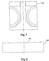
- This feature could be configured as a mesa 500 (which is the circular groove cut into the diaphragm substantially surrounding the flat mesa reflective surface of the diaphragm), a plug 600, or a bellows 700 as depicted in Figures 5, 6 , and 7 , respectively.
- the mesa diaphragm 500 includes a circular groove 510 cut therein.
- the circular groove 510 surrounds the reflective surface 549 of the diaphragm 500.
- Another way to improve the performance of the Fabry-Perot interferometer based sensor 10 is to attach a glass plate and/or dielectric coating 49 to the surface of the diaphragm 42 that allows the reflectance of the diaphragm 42 to be optimized and to remain uniform with time and temperature.
- the performance of the Fabry-Perot interferometer based sensor could be improved by machining a concave spherical depression 810 as depicted in Figure 8 in the center of the diaphragm 800 to provide modal control of the Fabry-Perot gap.
- the depth of the spherical depression must be less than the minimum gap that is to be measured with the Fabry-Perot sensor.
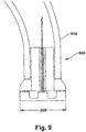
- the features of the second reflector in the Fabry-Perot interferometer based sensor combine to enable a transducer head 900 to be fabricated that is very short and very small in diameter.
- the small size allows the transducer head 900 to be placed on then end of a flexible probe 910 for use in locations where space and access are very limited, forming a flexible transducer.
- Combustor baskets in Siemens Westinghouse turbines contain J-tubes used to examine the combustor basket with a horoscope.
- a flexible transducer may be installed in this location but there are physical limitations to the size of the transducer head and the pigtail assembly that contains the leads. It is straightforward to design and build a fiber optic transducer that fits within the size envelope defined by the gas turbine combustor basket J-tube. One design is shown in Figure 9 . The size constraints include the diameter and length of the transducer and the flexibility of the pigtail assembly that must be pressure sealed.
Landscapes
- Physics & Mathematics (AREA)
- General Physics & Mathematics (AREA)
- Optics & Photonics (AREA)
- Engineering & Computer Science (AREA)
- Automation & Control Theory (AREA)
- Length Measuring Devices By Optical Means (AREA)
- Optical Couplings Of Light Guides (AREA)
- Investigating Or Analysing Materials By Optical Means (AREA)
Description
- The present invention relates to sensors for measuring the absolute length of a gap in a Fabry-Perot interferometer, and more particularly to a Fabry-Perot sensor that provides a more intense signal.
- The use of Fabry-Perot interferometers to measure the absolute length of a gap is known. Use of a ball lens to collimate light shining on a Fabry-Perot interferometer is needed for sensors measuring gaps exceeding about 30 µm in order to maintain a uniform optical path length for all light rays and to assure a high percentage of the light reflected by the interferometer is captured by the fiber. However, if the light delivery fiber is not precisely centered on the ball lens axis or if the interferometer is not precisely perpendicular to the axis of the incident light transmitted by the ball lens, then the reflected light from the diaphragm does not re-enter the fiber because the reflected light spot that is re-imaged by the ball lens is not centered on the end of the input fiber. As a result, if insufficient light reflected from the sensor re-enters the fiber, the results from the Fabry-Perot interferometer-based sensor are compromised.
- Accordingly, a Fabry-Perot interferometer-based sensor with a ball lens and alignment scheme that reflects high intensity light signals would provide benefits such as improved power budget, improved signal to noise ratio, and would be welcomed by the industry.
-
US 4,572,669 A discloses a method and related apparatus for implementing a unique multiple beam fringe sensor that is adapted to be interfaced with a low cost, compact fibre optic transmission system in order to provide an accurate digital representation of a physical parameter (e.g. temperature) of a remote sample. The sensor is fabricated so as to include a Fabry-Perot gap formed between the ends of two mated optical fibres. By examining the optical characteristics of light that is transmitted through the Fabry-Perot sensor gap, an indication of gap width can be ascertained. Accordingly, a change in Fabry-Perot sensor gap width is related to a change in the particular physical parameter to be measured. In another example, a second unique multiple beam fringe sensor having a Fabry-Perot gap is disclosed that is also adapted to provide an accurate digital representation of a physical parameter (e.g. temperature) of a remote sample. The sensor may be fabricated in two segments. A fibre containing segment includes each of a driving optical fibre for supplying incident light signals to the Fabry-Perot gap and a sensing optical fibre for receiving output light signals that have been transmitted twice through the Fabry-Perot gap, the optical characteristics of which output signals provide an indication of the parameter to be sensed. A transducer segment includes the Fabry-Perot gap formed therein and means responsive to the physical parameter for changing the width of the Fabry-Perot gap and, accordingly, the optical characteristics of the light signals passing therethrough. -
US 5,349,439 A discloses a measuring device comprising a light source with a wide spectrum feeding an optical sensor through an optical fibre. The sensor comprises an interferometer adjusted to a dull tint and an optical component sensitive to a measured parameter, which may be either a pressure, a measured displacement or an index of refraction of a fluid, a readout device includes the photodetector, a processing unit and an optical wedge for producing fringes, whose lateral positions, in contrast, are representative of the spectrum of the flux leaving the interferometer and analyzed by the photodetector. The processing unit measures the lateral position of the fringe and converts it into a value of the parameter P. -
US 2003/039428 A1 discloses an arrangement in which low coherence light of wide range is fed into a Fabry-Perot load cell having a measured clearance varied in response to physical quantities such as force and pressure or the like to modulate its wavelength. The measured clearance is calculated by the variable gap Fabry-Perot interferometer and the signal processing part in the optical sensor and further the physical quantities are measured. -
US 2004/086228 A1 discloses a method for making a fibre optic Fabry-Perot sensor that includes securing an optical fibre to a substrate, and forming at least one gap in the optical fibre after the optical fibre is secured to the substrate to define at least one pair of self-aligned opposing spaced apart optical fibre end faces for the Fabry-Perot sensor. Preferably, an adhesive directly secures the at least one pair of optical fibre portions to the substrate. The opposing spaced apart optical fibre end faces are self-aligned because the pair of optical fibre end portions are formed from a single fibre which has been directly secured to the substrate. Also, each of the self-aligned spaced apart optical fibre end faces may be substantially rounded due to an electrical discharge used to form the gap. This results in integral lenses being formed as the end faces of the fibre portions. -
US 6,854,899 B1 discloses a ferrule for an optical fibre is characterised in that the ferrule is produced from plastics material and is welded on the optical fibre, which also consists of plastics material, preferably by ultrasound. The cladding of the optical fibre comprises depressions which on welding also produce an interlocking fit in addition to the material connection. -
US 5,920,670 A discloses an optical fibre connector ferrule having a fibre engaging and alignment surface for engaging and aligning at least one optical fibre. The ferrule also has a connector engagement surface. Additionally, the connector ferrule of the present invention has the capability of providing multiple alignment methods for providing compatibility with many different connector devices. Examples of the multiple alignment methods include ball and socket alignment, pin and socket alignment, and edge alignment methods. -
US 6,430,337 B1 discloses an optical system with an optical assembly and a wavelength division multiplexer surface for transmitting a light beam. The optimal alignment of these light beams is accomplished by adjusting a steering device, which includes an optical wedge or a universal coupling, until the light path of the transmitted light beam through the optical assembly aligns with the light path of the transmitted light beam through the wavelength division multiplexing surface. -
US 2005/036742 A1 discloses a molded fiber optic ferrule that includes a ferrule body having an end face and a geometry feature integrally formed on an exterior surface of the ferrule body. The ferrule body defines a plurality of fiber bores for receiving end portions of optical fibers and at least one opening through the end face adapted to receive an alignment member for aligning the optical fibers with corresponding end portions of the opposing optical fibers of a mating multifiber ferrule. The geometry feature may include a geometric reference feature or an end face having a first surface normal to the longitudinal axis of the ferrule body and a second surface disposed at an angle relative to the first surface and the longitudinal axis. The geometric reference feature may be utilized to determine the angularity of the end face or the height of the optical fibers relative to the surface of the end face. -
US 2002/016536 A1 discloses a non-invasive near infrared spectrophotometric monitoring transducer assembly that includes a housing member, which is adhered directly on a patient's skin. -
GB 1,066,949 A Fig. 1A , for producing a pair of separated beams of radiation which impinge respectively on cube corner reflectors or other reflectors of a multiple reflecting kind, which are mounted on a gonior for angular movement as a unit about an axis perpendicular to the beams, the reflectors reflecting back beams in the same angular direction relative to the incident beams and regardless, within limits, of the angular position of the gonior to recombining means mounted on the stator, for producing interference fringes. - The invention provides a sensor assembly according to claim 1.
- Advantageous embodiments of the invention are defined in the dependent claims.
- Operation may be better understood by reference to the following detailed description taken in connection with the following illustrations, wherein:
-
Figure 1A is a concept drawing of a Fabry-Perot interferometer based sensor assembly with a ball lens and Fabry-Perot gap, wherein the window is a wedge with nonparallel surfaces. -
Figure 1B is a concept drawing of a Fabry-Perot interferometer based sensor assembly with a ball lens, a Fabry-Perot gap, and a wedge-shaped spacer that is used with a window having parallel surfaces. -
Figure 2 is a concept drawing of sensor assembly with ball lens and Fabry-Perot gap, wherein the two surfaces of the window are plane parallel (where one surface is a first reflector in a Fabry-Perot interferometer) and the transducer body is machined at the desired angle to maximize the reflected light signal. -
Figure 3 is a ray trace drawing of a 2mm diameter ball lens with de-centering of the delivery fiber relative to the ball lens and tilt of the diaphragm relative to the fiber, where the lens-to-window spacing = 0.1mm; the window thickness = 0.7mm; the window-reflector spacing (gap) = 1 mm; the fiber de-center = .05mm; and the tilt angle = 0.5°. -
Figure 4 is a ray trace drawing of a 2mm diameter ball lens with de-centering of the delivery fiber relative to the ball lens and no tilt of the diaphragm relative to the fiber (i.e., reflected rays do not re-enter fiber), where the lens-window spacing = 0.1mm; the window thickness = 0.7mm; the window-reflector spacing (gap) = 1 mm; the fiber de-center = .05mm; and the tilt angle = 0. -
Figure 5 shows a cross section of a second reflector in the Fabry-Perot interferometer with a mesa diaphragm configuration. -
Figure 6 shows a cross section of a second reflector in the Fabry-Perot interferometer with a plug diaphragm configuration. -
Figure 7 shows a cross section of a second reflector in the Fabry-Perot interferometer with a bellows diaphragm configuration. -
Figure 8 shows a cross section of a second reflector in the Fabry-Perot interferometer with a spherical depression. -
Figure 9 shows a flexible transducer incorporating an embodiment of a Fabry-Perot interferometer based sensor. -
Figure 10 shows a cross-section drawing of ball and socket alignment device of an optical fiber with fused ball lens. - While the present invention is described with reference to the embodiments described herein, it should be clear that the present invention should not be limited to such embodiments. Therefore, the description of the embodiments herein is illustrative of the present invention and should not limit the scope of the invention as claimed.
- To obtain the maximum light intensity using a Fabry-Perot interferometer based sensor, it is necessary to assure the optical fiber is precisely centered on the lens optical axis and the second reflector in the Fabry-Perot interferometer is precisely perpendicular to the beam of light transmitted from the lens. Since these conditions cannot be met precisely in manufacturing practice, certain adjustments are necessary to achieve these results. An embodiment of a Fabry-Perot interferometer based
sensor 10 is shown inFIG. 1A . In this embodiment, a wedge shapedwindow assembly 15 is used rather than a plane-parallel window as an alignment device. The Fabry-Perot interferometer basedsensor 10 comprises atransducer body 11, aferrule 20, anoptical fiber 25 having anoptical fiber axis 27, alens 30 having a lensoptical axis 32, and a Fabry-Perot sensor 40. Despite only a ball lens being shown inFIG. 1 , any sort of lens that focuses and collimates light can be used, e.g., a graded index lens or a ball lens. The Fabry-Perot sensor 40 comprises a wedge shapedwindow assembly 15 and adiaphragm 42 having anoptical axis 45 and areflective surface 49. The wedge shapedwindow assembly 15 comprises onesurface 52 that serves as the first partially reflector in a Fabry-Perot interferometer where thewindow assembly 15 is located between thelens 30 and asecond reflector 49 in the Fabry-Perot interferometer, which allows for proper operation of the invention with long gaps. Rotation of the wedge-shapedwindow assembly 15 causes a change in the angle of refraction into and out of thewindow assembly 15 until thewindow assembly 15 is in the precise rotational location where the column or beam of light transmitted from thelens 30, is perpendicular to the firstreflective surface 52 on thewindow assembly 15. Additionally, the lensoptical axis 32 is perpendicular to thesurface 49 of thediaphragm 42, as well as theoptical axis 27 of theoptical fiber 25 being perpendicular to the firstreflective surface 52 of thewindow assembly 15 and thesurface 49 of thediaphragm 42. - Alternatively, the window surfaces 51, 52 can be maintained parallel to each other and parallel to the
second reflector surface 49 in the Fabry-Perot sensor. Plane-parallel windows are easier to manufacture. In this embodiment, the alignment device comprises a wedge-shapedspacer 61 located between the lens and the reflective surface as shown inFIG. 1B . Accordingly, to provide the angle tuning, the wedge-shapedspacer 61 is inserted until the column or beam of light transmitted from thelens 30, is perpendicular to the reflective surface on the diaphragm.Spacers 61 with different wedge angles can be matched to different transducer bodies to correct for variation in manufacturing tolerances of the transducer bodies and to optimize light transmission. - As shown in
Figure 2 , a non-claimed example of a Fabry-Perot interferometer basedsensor 210 is shown. In this example, the Fabry-Perot interferometer basedsensor 210 maintains the window surfaces 251, 252 parallel to each other and parallel to thesecond reflector surface 249 in the Fabry-Perot sensor 240. To provide the angle tuning, the alignment device comprises asurface 213 of thetransducer body 211 that mates with thewindow assembly 215 that is machined at the desired angle after theball lens 230 andoptical fiber 225 assembly are bonded. In this example, thewindow assembly 215 does not need to be rotated to bring thewindow 215 into precise alignment with thetransducer 211. It is simply attached to thetransducer body 211 at any rotational position. Thetransducer body 211 is machined at a predetermined angle to produce the desired tilt angle of the Fabry-Perot interferometer based sensor. In other words, the alignment device comprises thetransducer body 211 having its end surface or face 213 machined at an angle relative to its axis to align the beam of light transmitted from the lens perpendicular with thereflective surface 249 of the diaphragm. The desired tilt angle of thetransducer body 211 is also when a light beam transmitted from theball lens 230 is perpendicular to theend face 213 of thetransducer body 211. This ensures the light beam is perpendicular to thediaphragm surface 249, as shown inFIG. 2 . This approach can also be used even when there is no ball lens and no window, to correct for any misalignment of the light beam with the transducer body and second reflector of the Fabry-Perot sensor, i.e. the diaphragm surface. - In an example not forming part of the invention, the method for pointing the light beam to achieve perpendicularity with the diaphragm is to use a metal ball-and-socket assembly shown in
Figure 10 . In this example the Fabry-Perot interferometer basedsensor 1000 comprises aferrule 1020, anoptical fiber 1025, alens 1030, a Fabry-Perot sensor 1040, and an alignment device. The alignment device comprises abody 1060 having asocket 1065, and aball 1070. The Fabry-Perot sensor 1040 comprises awindow assembly 1015 and adiaphragm 1042. Thewindow assembly 1015 comprises onesurface 1052 that serves as the first reflector in a Fabry-Perot interferometer where thewindow 1015 is between thelens 1030 and asecond reflector 1049 in the Fabry-Perot interferometer. This allows for proper operation in the case of long gaps. Thewindow assembly 1015 also includes anothersurface 1051 parallel to thesurface 1052. Theball 1070 can be a metal ball, but is not limited to such. It can be of any material. Theball 1070 is rotatably attached in thesocket 1065. Held inside themetal ball 1070 is theferrule 1020 that holds theoptical fiber 1025 andlens 1030. Themetal ball 1070 can be rotated in itsmating socket 1065 through two degrees of freedom about the center-of-rotation 1072, as shown by the arrow. In this manner the light beam angle transmitted from thelens 1030 is fine-tuned to be perpendicular to thediaphragm 1042surface 1049. - Various alternatives have been modeled using optical ray tracing software. In one embodiment, a 2mm diameter ball lens that is configured according to the drawing in
Figure 3 has the design parameters presented in Table 1.Table 1 Parameter definitions for design in Figure 3. For a lens with 2mm FS ball w 0.7mm thick window SRF RADIUS THICKNESS APERTURE RADIUS GLASS OBJ -- 0.530000 0.025000 AIR AST 1.000000 2.000000 0.119528 AS FK3 (fused silica) 2 -1.000000 0.100000 0.418365 S AIR 3 -- 0.700000 0.420979 S BK7 (glass) 4 -- 1.000000 0.433099 S AIR 5 -- -1.000000 0.459240 S REFL_HATCH * 6 -- -0.700000 0.485381 S BK7 7 -- -0.100000 0.497501 S AIR 8 -1.000000 -2.000000 0.500115 S FK3 9 1.000000 -0.530000 0.221589 S AIR IMS -- 0.060116 S *TILT/DECENTER DATA 0 DT 1 DCX -- DCY 0.050000 DCZ -- TLA -- TLB -- TLC -- 3 DT 1 DCX -- DCY -- DCZ -- TLA -0.500000 TLB -- TLC -- 5 DT 1 DCX -- DCY -- DCZ -- TLA -0.500000 TLB -- TLC -- 7 DT 1 DCX -- DCY -- DCZ -- TLA -0.500000 TLB -- TLC -- - The tilt angle is an input parameter to the ray trace. The same tilt angle is applied to each window surface C and D and the reflector E.
Figure 4 shows what happens if the fiber de-center remains 0.05mm and the tilt angle is set to 0. The reflected rays miss the end of the fiber. CompareFigure 4 withFigure 3 , where the reflected rays re-enter the fiber. The object and image size inFigure 3 is roughly .065mm (total spot size, not rms). InFigure 4 , the size of the image (reflected spot) is roughly .115mm and is not centered about the object (fiber end). - As previously discussed, a configuration to collimate light shining on the diaphragm of a fiber optic Fabry-Perot pressure sensor is shown in
Figures 1 and2 . A light delivery fiber and a ball lens are not attached to one another. - In addition to the alignment issues caused by the non-attached ball lens and fiber, the non-attached case results in two unwanted reflective surfaces (the fiber end and the ball lens input surface) that could interfere with the desired signal from the Fabry-Perot sensor. In the example shown in
Figure 10 , theball lens 1030 is attached to theoptical fiber 1025. More specifically, theball lens 1030 is fused and centered on the end of theoptical fiber 1025 minimizing the de-centering problem and eliminating two unwanted reflective surfaces. A ball lens is fused to the silica optical fiber by heating the end of the fiber to the melting point. During melting of the fiber, surface tension produces a sphere of transparent silica, and when the melted silica refreezes, the ball lens is permanently fused to the end of the fiber. Alternatively, theball lens 1030 can be bonded to theoptical fiber 1025 using an adhesive. The typical diameter of the ball lens formed in this manner is 340µm. - An additional way to improve the performance of the Fabry-Perot interferometer based sensor is to machine a feature (such as a circular groove) into the diaphragm that causes the surface of the diaphragm to translate without bending as the diaphragm deflects. This feature could be configured as a mesa 500 (which is the circular groove cut into the diaphragm substantially surrounding the flat mesa reflective surface of the diaphragm), a
plug 600, or abellows 700 as depicted inFigures 5, 6 , and7 , respectively. As shown inFIG. 5 , themesa diaphragm 500 includes acircular groove 510 cut therein. As shown, thecircular groove 510 surrounds thereflective surface 549 of thediaphragm 500. - Another way to improve the performance of the Fabry-Perot interferometer based
sensor 10 is to attach a glass plate and/ordielectric coating 49 to the surface of thediaphragm 42 that allows the reflectance of thediaphragm 42 to be optimized and to remain uniform with time and temperature. - Additionally, the performance of the Fabry-Perot interferometer based sensor could be improved by machining a concave
spherical depression 810 as depicted inFigure 8 in the center of thediaphragm 800 to provide modal control of the Fabry-Perot gap. The depth of the spherical depression must be less than the minimum gap that is to be measured with the Fabry-Perot sensor. - The features of the second reflector in the Fabry-Perot interferometer based sensor combine to enable a
transducer head 900 to be fabricated that is very short and very small in diameter. The small size allows thetransducer head 900 to be placed on then end of aflexible probe 910 for use in locations where space and access are very limited, forming a flexible transducer. In gas turbine applications where pressure pulsations in the combustor are to be monitored, it is desirable to install the pressure transducers and other sensors as close as possible to the combustion zone. Combustor baskets in Siemens Westinghouse turbines contain J-tubes used to examine the combustor basket with a horoscope. A flexible transducer may be installed in this location but there are physical limitations to the size of the transducer head and the pigtail assembly that contains the leads. It is straightforward to design and build a fiber optic transducer that fits within the size envelope defined by the gas turbine combustor basket J-tube. One design is shown inFigure 9 . The size constraints include the diameter and length of the transducer and the flexibility of the pigtail assembly that must be pressure sealed. - While the present invention has been described with reference to the preferred embodiment, obviously other embodiments, modifications, and alternations could be ascertained by one skilled in the art upon reading the present disclosed. The present invention is defined in the appended claims and covers these other embodiments, modifications, and alterations provided that they fall within the scope of the claims.
Claims (17)
- A sensor assembly comprising:an optical fiber (25) having an optical axis (27);a lens (30) in optical communication with said optical fiber (25), said lens (30) having an optical axis (32) and said lens (30) capable of transmitting a beam of light;a reflective surface (49), said reflective surface (49) spaced from said lens (30) such that said beam of light transmitted from said lens (30) is capable of reflecting from said reflective surface (49) back to said lens (30); andan alignment device comprising a wedge shaped window (15) or a wedge shaped spacer (61) located between said lens (30) and said reflective surface (49) and positioned such that, in use, it aligns said beam of light transmitted from said lens (30) substantially perpendicularly with said reflective surface (49).
- The sensor assembly of claim 1, wherein the alignment device comprises the wedge shaped spacer (61) located between said lens (30) and said reflective surface (49) and positioned such that, in use, it aligns said beam of light transmitted from said lens (30) substantially perpendicularly with said reflective surface (49),
the sensor assembly further comprising:
a transparent window (15) with a partially reflective surface (52), wherein said partially reflective surface (52) of said window (15) is substantially parallel with and is separated by a gap from said reflective surface (49), said optically transparent window (15) and said reflective surface (49) forming a Fabry-Perot sensor (40). - The sensor assembly of claim 2, wherein said lens (30) comprises at least one of: a ball lens (230); a graded index lens; a lens that focuses light; and a lens that collimates light.
- The sensor assembly of claim 3, further comprising a ferrule (20) encasing said optical fiber (25), said ferrule (20) aligning said optical axis (27) of said optical fiber (25) with said optical axis (32) of said lens (30).
- The sensor assembly of claim 3, wherein said ball lens (230) is attached to said optical fiber (25) to align said optical axis (27) of said optical fiber (25) with said optical axis (32) of said lens (30).
- The sensor assembly of claim 5, wherein said ball lens (230) is attached to said optical fiber (25) by melting or bonding said ball lens (230) to said optical fiber (25).
- The sensor assembly of claim 4, wherein said ball lens (230) is not attached to said optical fiber (25).
- The sensor assembly of claim 1, wherein said reflective surface (49) is a diaphragm (42).
- The sensor assembly of claim 8, wherein said diaphragm (42) comprises at least one of: a flat diaphragm; a mesa diaphragm; a plug diaphragm; and a bellows diaphragm.
- The sensor assembly of claim 8, wherein said diaphragm (42) has a dielectric reflective surface.
- The sensor assembly of claim 10, wherein said diaphragm (42) comprises a mesa diaphragm (500) , said mesa diaphragm (500) comprising a circular groove (510) substantially surrounding said dielectric reflective surface.
- The sensor assembly of claim 8, wherein said diaphragm (42) has a flat or a concave reflective surface.
- The sensor assembly of claim 1, further comprising a flexible tube (910) encasing at least a portion of said optical fiber (25) to form a flexible transducer.
- The sensor assembly of claim 1, wherein the alignment device comprises the wedge shaped spacer (61) located between said lens (30) and said reflective surface (49) and positioned such that, in use, it aligns said beam of light transmitted from said lens (30) substantially perpendicularly with said reflective surface (49),
wherein the sensor is a Fabry-Perot sensor assembly and the lens (30) is a ball lens; the sensor assembly further comprising:a window (15) having a first surface (51) and a second surface (52);a diaphragm (42) spaced from and parallel to said second surface (52) of said window (15), said diaphragm (42) including the reflective surface (49), and wherein the reflective surface (49) is partially reflective. - The sensor assembly of claim 14, wherein said ball lens (30) is attached to said optical fiber (25).
- The sensor assembly of claim 15, wherein attaching said ball lens (30) to said fiber (25) is accomplished by melting an end of said fiber (25) in a controlled manner.
- The sensor assembly of claim 14, further comprising a flexible tube (910) encasing at least a portion of said optical fiber (25) to form a flexible transducer.
Applications Claiming Priority (3)
| Application Number | Priority Date | Filing Date | Title |
|---|---|---|---|
| US66220205P | 2005-03-16 | 2005-03-16 | |
| US77428906P | 2006-02-17 | 2006-02-17 | |
| PCT/US2006/009400 WO2006101923A2 (en) | 2005-03-16 | 2006-03-16 | High intensity fabry-perot sensor |
Publications (3)
| Publication Number | Publication Date |
|---|---|
| EP1869737A2 EP1869737A2 (en) | 2007-12-26 |
| EP1869737A4 EP1869737A4 (en) | 2011-06-29 |
| EP1869737B1 true EP1869737B1 (en) | 2021-05-12 |
Family
ID=37024370
Family Applications (1)
| Application Number | Title | Priority Date | Filing Date |
|---|---|---|---|
| EP06738462.8A Expired - Lifetime EP1869737B1 (en) | 2005-03-16 | 2006-03-16 | High intensity fabry-perot sensor |
Country Status (3)
| Country | Link |
|---|---|
| US (2) | US20060274323A1 (en) |
| EP (1) | EP1869737B1 (en) |
| WO (1) | WO2006101923A2 (en) |
Cited By (1)
| Publication number | Priority date | Publication date | Assignee | Title |
|---|---|---|---|---|
| EP4571279A3 (en) * | 2023-12-15 | 2025-09-03 | Simmonds Precision Products, Inc. | Collimating etalons for pressure and temperature sensing |
Families Citing this family (24)
| Publication number | Priority date | Publication date | Assignee | Title |
|---|---|---|---|---|
| US7492463B2 (en) | 2004-04-15 | 2009-02-17 | Davidson Instruments Inc. | Method and apparatus for continuous readout of Fabry-Perot fiber optic sensor |
| EP1681540A1 (en) | 2004-12-21 | 2006-07-19 | Davidson Instruments, Inc. | Multi-channel array processor |
| EP1674833A3 (en) | 2004-12-21 | 2007-05-30 | Davidson Instruments, Inc. | Fiber optic sensor system |
| EP1869737B1 (en) | 2005-03-16 | 2021-05-12 | Davidson Instruments, Inc. | High intensity fabry-perot sensor |
| US8432552B2 (en) * | 2005-03-16 | 2013-04-30 | Halliburton Energy Services, Inc. | High intensity Fabry-Perot sensor |
| US7639368B2 (en) | 2005-09-13 | 2009-12-29 | Halliburton Energy Services, Inc. | Tracking algorithm for linear array signal processor for Fabry-Perot cross-correlation pattern and method of using same |
| US7684051B2 (en) | 2006-04-18 | 2010-03-23 | Halliburton Energy Services, Inc. | Fiber optic seismic sensor based on MEMS cantilever |
| EP2021747B1 (en) | 2006-04-26 | 2018-08-01 | Halliburton Energy Services, Inc. | Fiber optic mems seismic sensor with mass supported by hinged beams |
| US8115937B2 (en) | 2006-08-16 | 2012-02-14 | Davidson Instruments | Methods and apparatus for measuring multiple Fabry-Perot gaps |
| US7787128B2 (en) | 2007-01-24 | 2010-08-31 | Halliburton Energy Services, Inc. | Transducer for measuring environmental parameters |
| GB0724411D0 (en) * | 2007-12-14 | 2008-01-30 | Stfc Science & Technology | Optical sensor |
| EP2363685B1 (en) * | 2010-02-09 | 2013-11-20 | Attocube Systems AG | Positioning device with confocal Fabry-Perot interferometer |
| JP5434719B2 (en) * | 2010-03-19 | 2014-03-05 | セイコーエプソン株式会社 | Optical filters and analytical instruments |
| US8655117B2 (en) | 2011-03-11 | 2014-02-18 | University of Maribor | Optical fiber sensors having long active lengths, systems, and methods |
| GB2508908B (en) | 2012-12-14 | 2017-02-15 | Gen Electric | Resonator device |
| JP6089674B2 (en) * | 2012-12-19 | 2017-03-08 | セイコーエプソン株式会社 | Wavelength variable interference filter, method for manufacturing wavelength variable interference filter, optical filter device, optical module, and electronic apparatus |
| BR112016007183A2 (en) | 2013-12-20 | 2017-08-01 | Halliburton Energy Services Inc | apparatus, system and method for retrieving sensor data in a downhole profiling tool |
| JP2016065937A (en) * | 2014-09-24 | 2016-04-28 | パイオニア株式会社 | Variable wavelength optical filter and manufacturing method therefor |
| CN105509816B (en) | 2016-01-29 | 2018-02-16 | 苏州弘开传感科技有限公司 | A kind of sensor based on Fabry Perot principle |
| EP3482155B1 (en) * | 2016-07-05 | 2023-09-06 | The General Hospital Corporation | Common-path optical waveguide probe and method of manufacturing |
| CN106643918A (en) * | 2017-03-15 | 2017-05-10 | 中国科学院武汉岩土力学研究所 | Integrated test device for stress and displacement of rock mass based on fiber bragg grating and system |
| JP6754464B2 (en) * | 2019-04-23 | 2020-09-09 | パイオニア株式会社 | Tunable optical filter |
| US12560500B2 (en) | 2020-10-20 | 2026-02-24 | Davidson Instruments, Inc. | Extrinsic Fabry-Perot absolute pressure sensor |
| CN116839639A (en) * | 2022-03-24 | 2023-10-03 | 华为技术有限公司 | Optical fiber sensor and detection device |
Citations (1)
| Publication number | Priority date | Publication date | Assignee | Title |
|---|---|---|---|---|
| GB1066949A (en) * | 1962-10-02 | 1967-04-26 | Gen Precision Inc | Improvements in or relating to interferometric apparatus |
Family Cites Families (269)
| Publication number | Priority date | Publication date | Assignee | Title |
|---|---|---|---|---|
| US1432149A (en) | 1922-01-06 | 1922-10-17 | William E Bellingham | Automobile windshield accessory |
| GB1168971A (en) | 1966-07-08 | 1969-10-29 | Melvin Seymour Cook | Improvements in or relating to Optical Measurement of Length |
| US3923400A (en) | 1974-01-03 | 1975-12-02 | Itek Corp | Real-time wavefront correction system |
| US4572669A (en) | 1979-01-22 | 1986-02-25 | Rockwell International Corporation | Method and apparatus for a Fabry-Perot multiple beam fringe sensor |
| US4329058A (en) | 1979-01-22 | 1982-05-11 | Rockwell International Corporation | Method and apparatus for a Fabry-Perot multiple beam fringe sensor |
| US4210029A (en) | 1979-05-04 | 1980-07-01 | Lad Research Industries, Inc. | Differential fiber optic differential pressure sensor |
| DE3142164A1 (en) | 1980-10-27 | 1982-06-16 | Rosemount Engineering Co. Ltd., Bognor Regis, Sussex | DEVICE FOR MEASURING PRESSURE DIFFERENCES |
| DE3044183A1 (en) | 1980-11-24 | 1982-06-24 | Reinhard Dipl.-Phys. Dr. 7250 Leonberg Ulrich | METHOD FOR OPTICALLY MEASURING LENGTHS AND LENGTH CHANGES AND ARRANGEMENT FOR IMPLEMENTING THE METHOD |
| DE3172569D1 (en) | 1981-03-07 | 1985-11-14 | Kernforschungsz Karlsruhe | Differential pressure detector |
| DE3127333C2 (en) | 1981-07-10 | 1986-03-20 | Siemens Ag, 1000 Berlin Und 8000 Muenchen | Modulation device for optical signal transmission |
| US4418981A (en) | 1982-01-19 | 1983-12-06 | Gould Inc. | Quadrature fiber-optic interferometer matrix |
| JPS58208610A (en) | 1982-05-17 | 1983-12-05 | ブリティッシュ・テクノロジー・グループ・リミテッド | Device for inspecting surface |
| EP0120980B1 (en) | 1983-03-30 | 1987-06-24 | Ibm Deutschland Gmbh | Crosstalk compensation circuit for electro-optical scanning devices |
| DE3411096C2 (en) | 1983-06-30 | 1987-01-29 | Siemens AG, 1000 Berlin und 8000 München | Multi-channel measurement acquisition, transmission and processing system |
| US4606638A (en) | 1983-11-03 | 1986-08-19 | Zygo Corporation | Distance measuring interferometer and method of use |
| US4583228A (en) | 1983-11-21 | 1986-04-15 | At&T Bell Laboratories | Frequency stabilization of lasers |
| US4873989A (en) | 1984-03-08 | 1989-10-17 | Optical Technologies, Inc. | Fluid flow sensing apparatus for in vivo and industrial applications employing novel optical fiber pressure sensors |
| NO850865L (en) | 1984-03-10 | 1985-09-11 | Int Standard Electric Corp | FIBER OPTICAL SENSOR |
| US4907035A (en) | 1984-03-30 | 1990-03-06 | The Perkin-Elmer Corporation | Universal edged-based wafer alignment apparatus |
| GB8408383D0 (en) | 1984-03-31 | 1984-05-10 | Jackson D A | Optical pressure-sensing apparatus |
| US4640616A (en) | 1984-12-06 | 1987-02-03 | The Cambridge Instrument Company Plc | Automatic refractometer |
| US4648083A (en) | 1985-01-03 | 1987-03-03 | The United States Of America As Represented By The Secretary Of The Navy | All-optical towed and conformal arrays |
| JPS61235731A (en) | 1985-04-11 | 1986-10-21 | Sharp Corp | pressure sensitive element |
| JPS62201301A (en) | 1986-02-28 | 1987-09-05 | Tomohiko Akuta | Laser interferometric length measuring machine |
| US4668889A (en) | 1986-06-06 | 1987-05-26 | Adams Donald L | Static overpressure protection system for differential pressure transducer |
| US4755668A (en) | 1986-10-03 | 1988-07-05 | Optical Technologies, Inc. | Fiber optic interferometric thermometer with serially positioned fiber optic sensors |
| US4787741A (en) | 1986-10-09 | 1988-11-29 | Mcdonnell Douglas Corporation | Fiber optic sensor |
| US4777358A (en) | 1987-03-30 | 1988-10-11 | Geo-Centers, Inc. | Optical differential strain gauge |
| US4806016A (en) | 1987-05-15 | 1989-02-21 | Rosemount Inc. | Optical displacement sensor |
| DE3878400T2 (en) | 1987-10-28 | 1993-07-01 | Borg Warner Automotive | LINKED CHAIN FOR CONTINUOUSLY ADJUSTABLE GEARBOX WITH CURVED JOINT PIECES. |
| US4844616A (en) | 1988-05-31 | 1989-07-04 | International Business Machines Corporation | Interferometric dimensional measurement and defect detection method |
| US4972077A (en) | 1988-08-08 | 1990-11-20 | Schlumberger Industries Limited | Wavelength multiplexed optical transducer with a swept wavelength optical source |
| FR2641861B1 (en) | 1989-01-18 | 1993-04-30 | Photonetics | OPTO-ELECTRONIC MEASURING DEVICE |
| US4968144A (en) | 1989-03-09 | 1990-11-06 | Wayne State University | Single beam AC interferometer |
| US4914666A (en) | 1989-05-04 | 1990-04-03 | At&T Bell Laboratories | Random-access digitally -tuned optical frequency synthesizer |
| US4999014A (en) | 1989-05-04 | 1991-03-12 | Therma-Wave, Inc. | Method and apparatus for measuring thickness of thin films |
| US5060526A (en) | 1989-05-30 | 1991-10-29 | Schlumberger Industries, Inc. | Laminated semiconductor sensor with vibrating element |
| FR2647931B1 (en) | 1989-06-06 | 1994-09-09 | Thomson Csf | ARRAY OF SENSORS CONNECTED TO A REMOTE POWER, CONTROL AND PROCESSING PLANT |
| US4995697A (en) | 1989-09-07 | 1991-02-26 | The United States Of America As Represented By The Administrator Of The National Aeronautics And Space Administration | Fiber optic sensing system |
| GB8920364D0 (en) | 1989-09-08 | 1989-10-25 | Downs Michael J | Optical measuring instruments |
| US5034603A (en) | 1989-11-06 | 1991-07-23 | Wilson Keith E | Integrated optics wavelength stabilization unit |
| US5094534A (en) | 1989-12-27 | 1992-03-10 | Dylor Corporation | Coherence selective fiber optic interferometric sensor system |
| EP0445362B1 (en) | 1990-03-09 | 1993-07-28 | Landis & Gyr Business Support AG | Magnetic induction measuring apparatus |
| DE4016471A1 (en) | 1990-05-22 | 1991-11-28 | Bosch Gmbh Robert | MICROMECHANICAL INCLINATION SENSOR |
| EP0460357A3 (en) | 1990-06-08 | 1992-07-29 | Landis & Gyr Betriebs Ag | Device for optical measurement of pressure differences |
| GB9022969D0 (en) | 1990-10-23 | 1990-12-05 | Rosemount Ltd | Displacement measurement apparatus |
| US5225888A (en) | 1990-12-26 | 1993-07-06 | International Business Machines Corporation | Plasma constituent analysis by interferometric techniques |
| US5128798A (en) | 1991-02-07 | 1992-07-07 | International Business Machines Corporation | Addressable wedge etalon filter |
| US5835214A (en) | 1991-02-22 | 1998-11-10 | Applied Spectral Imaging Ltd. | Method and apparatus for spectral analysis of images |
| US5177805A (en) | 1991-04-01 | 1993-01-05 | American Research Corp. Of Va. | Optical sensors utilizing multiple reflection |
| US5784507A (en) | 1991-04-05 | 1998-07-21 | Holm-Kennedy; James W. | Integrated optical wavelength discrimination devices and methods for fabricating same |
| WO1992017757A1 (en) | 1991-04-05 | 1992-10-15 | Mark Iv Transducer Corporation | Differential pressure device |
| US6501551B1 (en) | 1991-04-29 | 2002-12-31 | Massachusetts Institute Of Technology | Fiber optic imaging endoscope interferometer with at least one faraday rotator |
| US5218426A (en) | 1991-07-01 | 1993-06-08 | The United States Of America As Represented By The Secretary Of Commerce | Highly accurate in-situ determination of the refractivity of an ambient atmosphere |
| US5239400A (en) | 1991-07-10 | 1993-08-24 | The Arizona Board Of Regents | Technique for accurate carrier frequency generation in of DM system |
| GB2258725B (en) | 1991-07-30 | 1995-06-21 | Rosemount Ltd | A method of decoding a spectrally modulated light signal |
| US5283625A (en) | 1991-08-19 | 1994-02-01 | Litton Systems, Inc. | Interferometer phase modulation controller apparatus using ratios of two pairs of harmonic signals |
| US5218418A (en) | 1991-10-30 | 1993-06-08 | Layton Michael R | Differential fiber optic sensor and method |
| US5181080A (en) | 1991-12-23 | 1993-01-19 | Therma-Wave, Inc. | Method and apparatus for evaluating the thickness of thin films |
| EP0562211A1 (en) * | 1992-03-25 | 1993-09-29 | International Business Machines Corporation | Self-aligning fiber couplers |
| FI98095C (en) | 1992-05-19 | 1997-04-10 | Vaisala Technologies Inc Oy | Optical power sensor based on a Fabry-Perot resonator and having a sweeping Fabry-Perot resonator as part of the detector |
| US5202939A (en) | 1992-07-21 | 1993-04-13 | Institut National D'optique | Fabry-perot optical sensing device for measuring a physical parameter |
| US5351317A (en) | 1992-08-14 | 1994-09-27 | Telefonaktiebolaget L M Ericsson | Interferometric tunable optical filter |
| US5361130A (en) | 1992-11-04 | 1994-11-01 | The United States Of America As Represented By The Secretary Of The Navy | Fiber grating-based sensing system with interferometric wavelength-shift detection |
| WO1994011708A1 (en) | 1992-11-06 | 1994-05-26 | Martin Marietta Corporation | Interferometric optical sensor read-out system |
| US5276501A (en) | 1992-11-06 | 1994-01-04 | Martin Marietta Corporation | Fabry-Perot readout technique using wavelength tuning |
| DE9215389U1 (en) | 1992-11-12 | 1994-03-17 | Flohe GmbH & Co, 44579 Castrop-Rauxel | Conductor section increasing the inductance of a cooled high-current cable |
| DE69229118T2 (en) | 1992-11-30 | 1999-08-26 | Stmicroelectronics S.R.L. | Generator architecture for single-port RAM with high performance |
| US5420688A (en) | 1992-12-14 | 1995-05-30 | Farah; John | Interferometric fiber optic displacement sensor |
| US5359681A (en) | 1993-01-11 | 1994-10-25 | University Of Washington | Fiber optic sensor and methods and apparatus relating thereto |
| DE4314486C2 (en) | 1993-05-03 | 1998-08-27 | Heidenhain Gmbh Dr Johannes | Absolute interferometric measurement method and suitable laser interferometer arrangement |
| US5559358A (en) | 1993-05-25 | 1996-09-24 | Honeywell Inc. | Opto-electro-mechanical device or filter, process for making, and sensors made therefrom |
| JPH0766482A (en) | 1993-08-26 | 1995-03-10 | Anritsu Corp | Variable wavelength light source |
| US5401958A (en) | 1993-09-08 | 1995-03-28 | General Electric Company | Optical temperature compensation of spectral modulation sensors by spectrographic interrogation having a dispersive element |
| US20020015155A1 (en) | 1993-09-21 | 2002-02-07 | Ralf-Dieter Pechstedt | Interferometer integrated on silicon-on-insulator chip |
| US5386729A (en) | 1993-09-22 | 1995-02-07 | The Babcock & Wilcox Company | Temperature compensated microbend fiber optic differential pressure transducer |
| US5401956A (en) | 1993-09-29 | 1995-03-28 | United Technologies Corporation | Diagnostic system for fiber grating sensors |
| US5451772A (en) | 1994-01-13 | 1995-09-19 | Mechanical Technology Incorporated | Distributed fiber optic sensor |
| US5509023A (en) | 1994-03-10 | 1996-04-16 | At&T Corp. | Laser control arrangement for tuning a laser |
| US5526114A (en) | 1994-07-20 | 1996-06-11 | Eselun; Steven A. | Time multiplexed fringe counter |
| US5497233A (en) | 1994-07-27 | 1996-03-05 | Litton Systems, Inc. | Optical waveguide vibration sensor and method |
| FI945124A0 (en) | 1994-10-31 | 1994-10-31 | Valtion Teknillinen | Spektrometer |
| US5550373A (en) | 1994-12-30 | 1996-08-27 | Honeywell Inc. | Fabry-Perot micro filter-detector |
| US5557406A (en) | 1995-02-28 | 1996-09-17 | The Texas A&M University System | Signal conditioning unit for fiber optic sensors |
| JP3304696B2 (en) | 1995-04-17 | 2002-07-22 | 株式会社先進材料利用ガスジェネレータ研究所 | Optical sensor |
| US5682237A (en) | 1995-05-26 | 1997-10-28 | McDonnell Douglas | Fiber strain sensor and system including one intrinsic and one extrinsic fabry-perot interferometer |
| US5646762A (en) | 1995-11-07 | 1997-07-08 | Lucent Technologies Inc. | Optical communication system using tandem Fabry-Perot etalon for wavelength selection |
| US5892357A (en) | 1995-12-08 | 1999-04-06 | Lockheed Martin Idaho Technologies Company | Electro-optic voltage sensor for sensing voltage in an E-field |
| US6307629B1 (en) | 1997-08-12 | 2001-10-23 | Lj Laboratories, L.L.C. | Apparatus and method for measuring optical characteristics of an object |
| US5641956A (en) | 1996-02-02 | 1997-06-24 | F&S, Inc. | Optical waveguide sensor arrangement having guided modes-non guided modes grating coupler |
| US5920670A (en) | 1996-06-07 | 1999-07-06 | 3M Innovative Properties Company | Multiple alignment connector ferrule |
| DE19615366B4 (en) | 1996-04-19 | 2006-02-09 | Carl Zeiss Jena Gmbh | Method and device for detecting physical, chemical, biological or biochemical reactions and interactions |
| FR2748578B1 (en) | 1996-05-10 | 1998-05-29 | Commissariat Energie Atomique | OPTOMECHANICAL DEVICE AND APPLICATION TO SENSORS IN INTEGRATED OPTICS |
| US6020963A (en) | 1996-06-04 | 2000-02-01 | Northeastern University | Optical quadrature Interferometer |
| DE19628200B4 (en) | 1996-07-12 | 2007-03-01 | Deutsches Zentrum für Luft- und Raumfahrt e.V. | Apparatus for performing interferometric measurements |
| US5832157A (en) | 1996-07-12 | 1998-11-03 | Mcdermott Technology, Inc. | Fiber optic acoustic emission sensor |
| US5760391A (en) | 1996-07-17 | 1998-06-02 | Mechanical Technology, Inc. | Passive optical wavelength analyzer with a passive nonuniform optical grating |
| US6088144A (en) | 1996-09-13 | 2000-07-11 | Lucent Technologies Inc. | Detection of frequency-modulated tones in electromagnetic signals |
| US5796007A (en) | 1996-09-23 | 1998-08-18 | Data Instruments, Inc. | Differential pressure transducer |
| US5872628A (en) | 1996-09-27 | 1999-02-16 | The Regents Of The University Of California | Noise pair velocity and range echo location system |
| US6940588B2 (en) | 1997-02-14 | 2005-09-06 | Jds Uniphase Inc. | Measuring response characteristics of an optical component |
| US5929990A (en) | 1997-03-19 | 1999-07-27 | Litton Systems, Inc. | Fabry-perot pressure sensing system with ratioed quadrature pulse detection |
| US5889590A (en) | 1997-03-28 | 1999-03-30 | General Electric Company | Optical cavity sensor |
| US5852498A (en) | 1997-04-04 | 1998-12-22 | Kairos Scientific Inc. | Optical instrument having a variable optical filter |
| US6281976B1 (en) | 1997-04-09 | 2001-08-28 | The Texas A&M University System | Fiber optic fiber Fabry-Perot interferometer diaphragm sensor and method of measurement |
| US5949740A (en) | 1997-06-06 | 1999-09-07 | Litton Systems, Inc. | Unbalanced fiber optic Michelson interferometer as an optical pick-off |
| US5963321A (en) | 1997-07-31 | 1999-10-05 | Virginia Tech Intellectual Properties, Inc. | Self-calibrating optical fiber pressure, strain and temperature sensors |
| IL121509A (en) | 1997-08-11 | 2000-02-17 | Eci Telecom Ltd | Device and method for monitoring and controlling laser wavelength |
| US6492636B1 (en) | 1997-08-19 | 2002-12-10 | The University Of Maryland | Large scale high speed multiplexed optical fiber sensor network |
| US6016702A (en) | 1997-09-08 | 2000-01-25 | Cidra Corporation | High sensitivity fiber optic pressure sensor for use in harsh environments |
| US5986749A (en) | 1997-09-19 | 1999-11-16 | Cidra Corporation | Fiber optic sensing system |
| EP1223439B1 (en) | 1997-10-20 | 2004-07-14 | Nippon Telegraph and Telephone Corporation | High speed wavelength discrimination apparatus |
| US5923030A (en) | 1997-11-10 | 1999-07-13 | The United States Of America As Represented By The Secretary Of The Navy | System and method for recovering a signal of interest from a phase modulated signal using quadrature sampling |
| US20010013934A1 (en) | 1997-11-15 | 2001-08-16 | Malcolm Paul Varnham | Seismic sensor with interferometric sensing apparatus |
| US6057911A (en) | 1997-11-17 | 2000-05-02 | Northrop Grumman Corporation | Fiber optic fabry-perot sensor for measuring absolute strain |
| US5999261A (en) | 1998-02-10 | 1999-12-07 | Seagate Technology, Inc. | Split phase high performance, high frequency, high dynamic range interferometer |
| US6151114A (en) | 1998-03-31 | 2000-11-21 | The Boeing Company | Coherent laser warning system |
| US6667935B2 (en) | 1998-04-03 | 2003-12-23 | The Board Of Trustees Of The Leland Stanford Junior University | Apparatus and method for processing optical signals from two delay coils to increase the dynamic range of a sagnac-based fiber optic sensor array |
| DE19817357B4 (en) | 1998-04-18 | 2008-10-30 | Robert Bosch Gmbh | Micromechanical component |
| US6115521A (en) * | 1998-05-07 | 2000-09-05 | Trw Inc. | Fiber/waveguide-mirror-lens alignment device |
| RU2152601C1 (en) | 1998-06-16 | 2000-07-10 | Научный центр волоконной оптики при Институте общей физики РАН | Fiber-optic pressure transducer (design versions) and its manufacturing process |
| US5949801A (en) | 1998-07-22 | 1999-09-07 | Coretek, Inc. | Tunable laser and method for operating the same |
| US6118534A (en) | 1998-07-30 | 2000-09-12 | B. F. Goodrich Company | Sensor and method for measuring changes in environmental conditions |
| US6522797B1 (en) | 1998-09-01 | 2003-02-18 | Input/Output, Inc. | Seismic optical acoustic recursive sensor system |
| US6137621A (en) | 1998-09-02 | 2000-10-24 | Cidra Corp | Acoustic logging system using fiber optics |
| US6430337B1 (en) * | 1998-09-03 | 2002-08-06 | Agere Systems Optoelectronics Guardian Corp. | Optical alignment system |
| US6078706A (en) | 1998-09-22 | 2000-06-20 | The United States Of America As Represented By The Secretary Of The Navy | Quasi-static fiber pressure sensor |
| US6122415A (en) | 1998-09-30 | 2000-09-19 | Blake; James N. | In-line electro-optic voltage sensor |
| US6282215B1 (en) | 1998-10-16 | 2001-08-28 | New Focus, Inc. | Continuously-tunable external cavity laser |
| US6331892B1 (en) | 1998-10-16 | 2001-12-18 | New Focus, Inc. | Interferometer for monitoring wavelength in an optical beam |
| BR9915956B1 (en) | 1998-12-04 | 2011-10-18 | pressure sensor, and method for sensing pressure. | |
| US6310990B1 (en) | 2000-03-16 | 2001-10-30 | Cidra Corporation | Tunable optical structure featuring feedback control |
| EP1137920B1 (en) | 1998-12-04 | 2005-02-16 | Weatherford/Lamb, Inc. | Bragg grating pressure sensor |
| US6396605B1 (en) | 1999-01-26 | 2002-05-28 | Trw Inc. | Apparatus and method for tuning an optical interferometer |
| US6330388B1 (en) | 1999-01-27 | 2001-12-11 | Northstar Photonics, Inc. | Method and apparatus for waveguide optics and devices |
| US6075613A (en) | 1999-02-26 | 2000-06-13 | General Scanning, Inc. | Optical scanner calibration device |
| US6714566B1 (en) | 1999-03-01 | 2004-03-30 | The Regents Of The University Of California | Tunable laser source with an integrated wavelength monitor and method of operating same |
| US7047054B2 (en) * | 1999-03-12 | 2006-05-16 | Cas Medical Systems, Inc. | Laser diode optical transducer assembly for non-invasive spectrophotometric blood oxygenation monitoring |
| US6545760B1 (en) | 1999-03-25 | 2003-04-08 | The United States Of America As Represented By The Administrator Of The National Aeronautics And Space Administration | Apparatus and method for measuring strain in optical fibers using rayleigh scatter |
| KR100332833B1 (en) | 1999-04-23 | 2002-04-17 | 윤덕용 | Transmission-type extrinsic Fabry-Perot interferometric optical fiber sensor |
| DE19923246A1 (en) * | 1999-05-20 | 2000-12-07 | Tyco Electronics Logistics Ag | Ferrule for an optical fiber and method for attaching the ferrule to the optical fiber |
| US6486984B1 (en) | 1999-06-07 | 2002-11-26 | Agilent Technologies, Inc. | Wavelength monitor using hybrid approach |
| US6771905B1 (en) | 1999-06-07 | 2004-08-03 | Corvis Corporation | Optical transmission systems including optical switching devices, control apparatuses, and methods |
| US6469817B1 (en) | 1999-06-18 | 2002-10-22 | Trw Inc. | Apparatus and method employing two optical signals for stabilizing an optical interferometer |
| GB2353139B (en) | 1999-08-12 | 2001-08-29 | United Microelectronics Corp | Inductor and method of manufacturing the same |
| CA2386150A1 (en) | 1999-08-23 | 2001-03-22 | Coretek, Inc. | Wavelength reference device |
| US6178001B1 (en) | 1999-09-08 | 2001-01-23 | Nortel Networks Limited | Method and apparatus for optical frequency modulation characterization of laser sources |
| NO324337B1 (en) | 1999-09-15 | 2007-09-24 | Optoplan As | Device for painting optical wavelengths |
| US6493088B1 (en) | 1999-10-04 | 2002-12-10 | Nortel Networks Limited | Method and apparatus for high resolution monitoring of optical signals |
| US6212306B1 (en) | 1999-10-07 | 2001-04-03 | David J. F. Cooper | Method and device for time domain demultiplexing of serial fiber Bragg grating sensor arrays |
| US6439055B1 (en) | 1999-11-15 | 2002-08-27 | Weatherford/Lamb, Inc. | Pressure sensor assembly structure to insulate a pressure sensing device from harsh environments |
| US6388434B1 (en) | 2000-01-17 | 2002-05-14 | Bechtel Bwxt Idaho, Llc | Electro-optic high voltage sensor |
| US6304686B1 (en) | 2000-02-09 | 2001-10-16 | Schlumberger Technology Corporation | Methods and apparatus for measuring differential pressure with fiber optic sensor systems |
| WO2001059419A1 (en) | 2000-02-11 | 2001-08-16 | Rosemount Inc. | Optical pressure sensor |
| US6496265B1 (en) | 2000-02-16 | 2002-12-17 | Airak, Inc. | Fiber optic sensors and methods therefor |
| JP3288672B2 (en) | 2000-02-17 | 2002-06-04 | 科学技術振興事業団 | Equipment for measuring physical properties of samples |
| US6603560B1 (en) | 2000-03-15 | 2003-08-05 | The Regents Of The University Of Michigan | High sensitivity fiber optic interferometric MEMS |
| US6583882B2 (en) | 2000-03-17 | 2003-06-24 | Honeywell International Inc. | Apparatus and method using digitally controlled integration for signal detection with improved noise characteristics |
| DE10014175C2 (en) | 2000-03-23 | 2002-12-12 | Daimler Chrysler Ag | Arrangement of several fiber-optic Bragg grating sensors and method for determining measured values in one |
| JP4460031B2 (en) * | 2000-03-28 | 2010-05-12 | 古河電気工業株式会社 | Arrayed waveguide grating |
| US6328647B1 (en) | 2000-04-06 | 2001-12-11 | Jon E. Traudt | Pressure differential detecting system, and method of use |
| US6538748B1 (en) | 2000-04-14 | 2003-03-25 | Agilent Technologies, Inc | Tunable Fabry-Perot filters and lasers utilizing feedback to reduce frequency noise |
| NL1015131C1 (en) | 2000-04-16 | 2001-10-19 | Tmp Total Micro Products B V | Apparatus and method for switching electromagnetic signals or beams. |
| DE10021669A1 (en) | 2000-05-05 | 2001-11-08 | Abb Research Ltd | Fiber optic current sensor |
| US6608685B2 (en) | 2000-05-15 | 2003-08-19 | Ilx Lightwave Corporation | Tunable Fabry-Perot interferometer, and associated methods |
| US6838660B2 (en) | 2000-06-02 | 2005-01-04 | Airak, Inc. | Fiber optic sensor system and method for measuring the pressure of media |
| US6668105B2 (en) | 2000-07-27 | 2003-12-23 | Systems Planning & Analysis, Inc. | Fiber optic strain sensor |
| WO2002010677A1 (en) | 2000-08-01 | 2002-02-07 | The Government Of The United States Of America, As Represented By The Secretary Of The Navy | Optical sensing device containing fiber bragg gratings |
| US6333941B1 (en) | 2000-08-01 | 2001-12-25 | Micro Photonix Integration Corporation | Tunable optical transmitter and tunable light source |
| JP3549153B2 (en) | 2000-09-20 | 2004-08-04 | 株式会社共和電業 | Optical fiber interference sensor, signal processing system for optical fiber interference sensor, signal processing method, and recording medium |
| US6687036B2 (en) | 2000-11-03 | 2004-02-03 | Nuonics, Inc. | Multiplexed optical scanner technology |
| US6747743B2 (en) | 2000-11-10 | 2004-06-08 | Halliburton Energy Services, Inc. | Multi-parameter interferometric fiber optic sensor |
| US6785004B2 (en) | 2000-11-29 | 2004-08-31 | Weatherford/Lamb, Inc. | Method and apparatus for interrogating fiber optic sensors |
| US20020109081A1 (en) | 2000-12-20 | 2002-08-15 | Tarvin Jeffrey A. | Measuring system with comb filter interferometer and multiplexer |
| KR100388499B1 (en) | 2000-12-22 | 2003-06-25 | 한국전자통신연구원 | Optical tunable filters and optical communication device using the optical tunable filters |
| US6690687B2 (en) | 2001-01-02 | 2004-02-10 | Spectrasensors, Inc. | Tunable semiconductor laser having cavity with ring resonator mirror and mach-zehnder interferometer |
| WO2002063372A1 (en) | 2001-01-16 | 2002-08-15 | Santur Corporation | Tunable optical device using a scanning mems mirror |
| US6597458B2 (en) | 2001-02-02 | 2003-07-22 | Texas Christian University | Method and system for stabilizing and demodulating an interferometer at quadrature |
| US6778307B2 (en) | 2001-02-21 | 2004-08-17 | Beyond 3, Inc. | Method and system for performing swept-wavelength measurements within an optical system |
| US6735224B2 (en) | 2001-03-01 | 2004-05-11 | Applied Optoelectronics, Inc. | Planar lightwave circuit for conditioning tunable laser output |
| US6925213B2 (en) | 2001-03-09 | 2005-08-02 | University Of Cincinnati | Micromachined fiber optic sensors |
| US6581465B1 (en) | 2001-03-14 | 2003-06-24 | The United States Of America As Represented By The Secretary Of The Navy | Micro-electro-mechanical systems ultra-sensitive accelerometer |
| US6717965B2 (en) | 2001-07-06 | 2004-04-06 | Intel Corporation | Graded thin film wedge interference filter and method of use for laser tuning |
| US6643025B2 (en) | 2001-03-29 | 2003-11-04 | Georgia Tech Research Corporation | Microinterferometer for distance measurements |
| AU2002256193A1 (en) | 2001-04-11 | 2002-10-28 | Modern Optical Technologies Llc. | Method and apparatus for measuring pressure |
| GB2375184A (en) | 2001-05-02 | 2002-11-06 | Marconi Caswell Ltd | Wavelength selectable optical filter |
| US20030020926A1 (en) | 2001-05-15 | 2003-01-30 | Nicolae Miron | Tunable band pass optical filter unit with a tunable band pass interferometer |
| US6909548B2 (en) | 2001-06-13 | 2005-06-21 | Jds Uniphase Inc. | Optical filter using a linear variable filter with elliptical beam geometry |
| US6915048B2 (en) | 2001-06-18 | 2005-07-05 | Cidra Corporation | Fabry-perot filter/resonator |
| US6898338B2 (en) | 2001-06-18 | 2005-05-24 | Weatherford/Lamb, Inc. | Fabry-Perot sensing element based on a large-diameter optical waveguide |
| US6668111B2 (en) | 2001-06-28 | 2003-12-23 | The Charles Stark Draper Laboratory | Optical microcavity resonator sensor |
| US6901088B2 (en) | 2001-07-06 | 2005-05-31 | Intel Corporation | External cavity laser apparatus with orthogonal tuning of laser wavelength and cavity optical pathlength |
| US6822979B2 (en) | 2001-07-06 | 2004-11-23 | Intel Corporation | External cavity laser with continuous tuning of grid generator |
| US6631146B2 (en) | 2001-07-06 | 2003-10-07 | Intel Corporation | Tunable laser control system |
| EP1421421A4 (en) | 2001-07-20 | 2005-10-05 | Essex Corp | Method and apparatus for optical signal processing using an optical tapped delay line |
| JP2004537750A (en) | 2001-08-02 | 2004-12-16 | アイギス セミコンダクター インコーポレイテッド | Tunable optics |
| US6741357B2 (en) | 2001-08-14 | 2004-05-25 | Seagate Technology Llc | Quadrature phase shift interferometer with unwrapping of phase |
| US6914681B2 (en) | 2001-08-22 | 2005-07-05 | Agilent Technologies, Inc. | Interferometric optical component analyzer based on orthogonal filters |
| US6882428B2 (en) | 2001-08-28 | 2005-04-19 | Agilent Technologies, Inc. | Optical analyzer and method for reducing relative intensity noise in interferometric optical measurements using a continuously tunable laser |
| US6985235B2 (en) | 2001-08-30 | 2006-01-10 | Micron Optics, Inc. | Cascaded fiber fabry-perot filters |
| KR100419424B1 (en) | 2001-09-22 | 2004-02-19 | 삼성전자주식회사 | Apparatus for optical signal performance monitoring in wavelength division multiplexing system |
| US6549687B1 (en) | 2001-10-26 | 2003-04-15 | Lake Shore Cryotronics, Inc. | System and method for measuring physical, chemical and biological stimuli using vertical cavity surface emitting lasers with integrated tuner |
| WO2003040648A1 (en) | 2001-11-05 | 2003-05-15 | Zygo Corporation | Interferometric cyclic error compensation |
| NO315177B1 (en) | 2001-11-29 | 2003-07-21 | Sinvent As | Optical offset sensor |
| US6776049B2 (en) | 2001-12-07 | 2004-08-17 | Alliant Techsystems Inc. | System and method for measuring stress at an interface |
| US6894787B2 (en) * | 2001-12-21 | 2005-05-17 | Honeywell International Inc. | Optical pressure sensor |
| US20030132375A1 (en) | 2002-01-17 | 2003-07-17 | Blazo Stephen Frank | Tunable laser calibration system |
| US6816514B2 (en) | 2002-01-24 | 2004-11-09 | Np Photonics, Inc. | Rare-earth doped phosphate-glass single-mode fiber lasers |
| KR100412324B1 (en) | 2002-01-28 | 2003-12-31 | 주식회사 아이세스 | Multi-type FBG sensor system |
| US6868736B2 (en) | 2002-02-22 | 2005-03-22 | Sentec Corporation | Ultra-miniature optical pressure sensing system |
| US7230959B2 (en) | 2002-02-22 | 2007-06-12 | Intel Corporation | Tunable laser with magnetically coupled filter |
| US6650420B2 (en) | 2002-02-27 | 2003-11-18 | The United States Of America As Represented By The Secretary Of The Navy | Nanoscale vibrometric measurement apparatus and method |
| US6825934B2 (en) | 2002-03-14 | 2004-11-30 | Agilent Technologies, Inc. | Vibration noise mitigation in an interferometric system |
| US7317739B2 (en) | 2002-03-15 | 2008-01-08 | Princeton University | Mode-locked laser using a mode-locking wavelength selective reflector |
| US6917736B1 (en) | 2002-05-09 | 2005-07-12 | Purdue Research Foundation | Method of increasing number of allowable channels in dense wavelength division multiplexing |
| US7009691B2 (en) | 2002-05-29 | 2006-03-07 | Agilent Technologies, Inc. | System and method for removing the relative phase uncertainty in device characterizations performed with a polarimeter |
| US6647160B1 (en) | 2002-06-17 | 2003-11-11 | National Chiao Tung University | Fiber bragg grating sensor system |
| DE60202137T2 (en) | 2002-06-19 | 2005-03-31 | John R. Sandercock | Stabilized Fabry-Perot interferometer and method for stabilizing a Fabry-Perot interferometer |
| US6850461B2 (en) | 2002-07-18 | 2005-02-01 | Pgs Americas, Inc. | Fiber-optic seismic array telemetry, system, and method |
| TW531671B (en) | 2002-07-22 | 2003-05-11 | Delta Electronics Inc | Tunable filter applied in optical networks |
| US6947218B2 (en) | 2002-08-30 | 2005-09-20 | Research Electro-Optics, Inc. | Fabry-perot etalon with independently selectable resonance frequency and free spectral range |
| US7139081B2 (en) | 2002-09-09 | 2006-11-21 | Zygo Corporation | Interferometry method for ellipsometry, reflectometry, and scatterometry measurements, including characterization of thin film structures |
| AU2003278933A1 (en) | 2002-09-26 | 2004-04-19 | Prime Photonics, Inc. | Active q-point stabilization for linear interferometric sensors |
| US6901176B2 (en) | 2002-10-15 | 2005-05-31 | University Of Maryland | Fiber tip based sensor system for acoustic measurements |
| TW557365B (en) | 2002-10-16 | 2003-10-11 | Delta Electronics Inc | Fabry-Perot device compensating for an error of full width at half maximum and method of making the same |
| US6842254B2 (en) | 2002-10-16 | 2005-01-11 | Fiso Technologies Inc. | System and method for measuring an optical path difference in a sensing interferometer |
| US6886365B2 (en) | 2002-11-04 | 2005-05-03 | Harris Corporation | Fiber optic Fabry-Perot interferometer and associated methods |
| US6933491B2 (en) | 2002-12-12 | 2005-08-23 | Weatherford/Lamb, Inc. | Remotely deployed optical fiber circulator |
| US6898339B2 (en) | 2002-12-16 | 2005-05-24 | Schlumberger Technology Corporation | Multiple mode pre-loadable fiber optic pressure and temperature sensor |
| DE60221681T2 (en) | 2002-12-16 | 2008-04-30 | Aston Photonic Technologies Ltd. | Optical waveguide grating interrogation system and sensor system |
| US7063466B2 (en) | 2002-12-20 | 2006-06-20 | Micron Optics, Inc. | Selectable and tunable ferrule holder for a fiber Fabry-Perot filter |
| US7065108B2 (en) | 2002-12-24 | 2006-06-20 | Electronics And Telecommunications Research Institute | Method of wavelength tuning in a semiconductor tunable laser |
| JP4062606B2 (en) | 2003-01-20 | 2008-03-19 | フジノン株式会社 | Low coherence measurement / high coherence measurement common interferometer apparatus and measurement method thereof |
| US7139295B2 (en) | 2003-01-27 | 2006-11-21 | Fibera, Inc. | Tunable wavelength locker, tunable wavelength spectrum monitor, and relative wavelength measurement system |
| GB0302434D0 (en) | 2003-02-03 | 2003-03-05 | Sensor Highway Ltd | Interferometric method and apparatus for measuring physical parameters |
| US6886404B2 (en) | 2003-02-05 | 2005-05-03 | Fibersonde Corporation | Fiber optic accelerometer |
| US7047816B2 (en) | 2003-03-21 | 2006-05-23 | Weatherford/Lamb, Inc. | Optical differential pressure transducer utilizing a bellows and flexure system |
| US6879421B2 (en) | 2003-03-28 | 2005-04-12 | Beyond 3, Inc. | Method and system for performing swept-wavelength measurements within an optical system incorporating a reference resonator |
| US6955085B2 (en) | 2003-06-02 | 2005-10-18 | Weatherford/Lamb, Inc. | Optical accelerometer or displacement device using a flexure system |
| US7099015B2 (en) | 2003-08-25 | 2006-08-29 | Ivan Melnyk | Fiber optic sensing device for measuring a physical parameter |
| US7019837B2 (en) | 2003-08-27 | 2006-03-28 | Weatherford/Lamb, Inc | Method and apparatus for reducing crosstalk interference in an inline Fabry-Perot sensor array |
| US20050036742A1 (en) | 2003-08-29 | 2005-02-17 | Dean David L. | Molded fiber optic ferrule with integrally formed geometry features |
| WO2005024365A2 (en) | 2003-09-04 | 2005-03-17 | Luna Energy, Llc | Optical sensor with co-located pressure and temperature sensors |
| WO2005033643A2 (en) | 2003-10-03 | 2005-04-14 | Sabeus, Inc. | Rugged fabry-perot pressure sensor |
| US20050073690A1 (en) | 2003-10-03 | 2005-04-07 | Abbink Russell E. | Optical spectroscopy incorporating a vertical cavity surface emitting laser (VCSEL) |
| US6829073B1 (en) | 2003-10-20 | 2004-12-07 | Corning Incorporated | Optical reading system and method for spectral multiplexing of resonant waveguide gratings |
| US7173713B2 (en) * | 2004-03-04 | 2007-02-06 | Virginia Tech Intellectual Properties, Inc. | Optical fiber sensors for harsh environments |
| US7183531B2 (en) | 2004-03-31 | 2007-02-27 | Micron Technology, Inc. | Amplification with feedback capacitance for photodetector signals |
| US7305158B2 (en) | 2004-04-15 | 2007-12-04 | Davidson Instruments Inc. | Interferometric signal conditioner for measurement of absolute static displacements and dynamic displacements of a Fabry-Perot interferometer |
| US7134346B2 (en) | 2004-04-15 | 2006-11-14 | Davidson Instruments Inc. | Differential pressure transducer with Fabry-Perot fiber optic displacement sensor |
| EP1586854A3 (en) | 2004-04-15 | 2006-02-08 | Davidson Instruments | Interferometric signal conditioner for measurement of the absolute length of gaps in a fiber optic Fabry-Pérot interferometer |
| US7492463B2 (en) | 2004-04-15 | 2009-02-17 | Davidson Instruments Inc. | Method and apparatus for continuous readout of Fabry-Perot fiber optic sensor |
| US7355726B2 (en) | 2004-04-15 | 2008-04-08 | Davidson Instruments Inc. | Linear variable reflector sensor and signal processor |
| US7187453B2 (en) | 2004-04-23 | 2007-03-06 | Opsens Inc. | Optical MEMS cavity having a wide scanning range for measuring a sensing interferometer |
| US20050242096A1 (en) | 2004-04-29 | 2005-11-03 | Jaghab John J | Safety cup lip |
| US20060034569A1 (en) | 2004-08-11 | 2006-02-16 | General Electric Company | Novel folded Mach-Zehnder interferometers and optical sensor arrays |
| US7511823B2 (en) | 2004-12-21 | 2009-03-31 | Halliburton Energy Services, Inc. | Fiber optic sensor |
| EP1674833A3 (en) | 2004-12-21 | 2007-05-30 | Davidson Instruments, Inc. | Fiber optic sensor system |
| EP1681540A1 (en) | 2004-12-21 | 2006-07-19 | Davidson Instruments, Inc. | Multi-channel array processor |
| EP1869737B1 (en) | 2005-03-16 | 2021-05-12 | Davidson Instruments, Inc. | High intensity fabry-perot sensor |
| US7405829B2 (en) | 2005-06-17 | 2008-07-29 | Jds Uniphase Corporation | Apparatus and method for characterizing pulsed optical signals |
| US7639368B2 (en) | 2005-09-13 | 2009-12-29 | Halliburton Energy Services, Inc. | Tracking algorithm for linear array signal processor for Fabry-Perot cross-correlation pattern and method of using same |
| US20080297808A1 (en) | 2005-12-06 | 2008-12-04 | Nabeel Agha Riza | Optical Sensor For Extreme Environments |
| US20070252998A1 (en) | 2006-03-22 | 2007-11-01 | Berthold John W | Apparatus for continuous readout of fabry-perot fiber optic sensor |
| WO2007126491A2 (en) | 2006-03-31 | 2007-11-08 | Davidson Instruments, Inc. | Differential pressure transducer configurations including displacement sensor |
| US7684051B2 (en) | 2006-04-18 | 2010-03-23 | Halliburton Energy Services, Inc. | Fiber optic seismic sensor based on MEMS cantilever |
| EP2021747B1 (en) | 2006-04-26 | 2018-08-01 | Halliburton Energy Services, Inc. | Fiber optic mems seismic sensor with mass supported by hinged beams |
| US8115937B2 (en) | 2006-08-16 | 2012-02-14 | Davidson Instruments | Methods and apparatus for measuring multiple Fabry-Perot gaps |
| US7787128B2 (en) | 2007-01-24 | 2010-08-31 | Halliburton Energy Services, Inc. | Transducer for measuring environmental parameters |
-
2006
- 2006-03-16 EP EP06738462.8A patent/EP1869737B1/en not_active Expired - Lifetime
- 2006-03-16 WO PCT/US2006/009400 patent/WO2006101923A2/en not_active Ceased
- 2006-03-16 US US11/377,050 patent/US20060274323A1/en active Granted
-
2009
- 2009-02-04 US US12/365,700 patent/US7782465B2/en not_active Expired - Lifetime
Patent Citations (1)
| Publication number | Priority date | Publication date | Assignee | Title |
|---|---|---|---|---|
| GB1066949A (en) * | 1962-10-02 | 1967-04-26 | Gen Precision Inc | Improvements in or relating to interferometric apparatus |
Cited By (1)
| Publication number | Priority date | Publication date | Assignee | Title |
|---|---|---|---|---|
| EP4571279A3 (en) * | 2023-12-15 | 2025-09-03 | Simmonds Precision Products, Inc. | Collimating etalons for pressure and temperature sensing |
Also Published As
| Publication number | Publication date |
|---|---|
| EP1869737A4 (en) | 2011-06-29 |
| US20090207417A1 (en) | 2009-08-20 |
| WO2006101923A3 (en) | 2008-01-17 |
| US20060274323A1 (en) | 2006-12-07 |
| WO2006101923A2 (en) | 2006-09-28 |
| EP1869737A2 (en) | 2007-12-26 |
| US7782465B2 (en) | 2010-08-24 |
Similar Documents
| Publication | Publication Date | Title |
|---|---|---|
| EP1869737B1 (en) | High intensity fabry-perot sensor | |
| US8432552B2 (en) | High intensity Fabry-Perot sensor | |
| US9989385B2 (en) | Method of assembling an optical sensor | |
| US5425273A (en) | Fiber optic pressure sensor with inclusions in a compressible transparent material | |
| US10162114B2 (en) | Reflective optical coherence tomography probe | |
| EP0189966B1 (en) | Method for aligning optical fiber connectors | |
| US7787128B2 (en) | Transducer for measuring environmental parameters | |
| EP2951547B1 (en) | Optical sensor for contactless pressure measurements | |
| US9933244B2 (en) | Reduced back reflection optical coherence tomography probe | |
| US20080239323A1 (en) | Chromatic confocal sensor fiber interface | |
| CN218598303U (en) | Fan blade load monitoring device | |
| US5149963A (en) | Fiber-optic position sensor including photovoltaic bi-cell | |
| US9829307B2 (en) | Silicon based pressure and acceleration optical interferometric sensors with housing assembly | |
| US20230393005A1 (en) | Extrinsic fabry-perot absolute pressure sensor | |
| CN119714502A (en) | Optical fiber Fabry-Perot sound sensor and preparation method thereof | |
| US20060209396A1 (en) | Monitoring device | |
| JP2006208929A (en) | Optical power monitor and its manufacturing method | |
| KR20120036351A (en) | Pressure measuring cell arrangement comprising an optical diaphragm prssure measuing cell | |
| CN117906804B (en) | Pressure sensor | |
| CN113753844A (en) | Optical-mechanical transducer device and corresponding method | |
| Mignani et al. | Radially gradient-index lenses: applications to fiber optic sensors | |
| CN118150308A (en) | Side pressure type tension measuring device | |
| CN117157512A (en) | Monitoring system based on optical MEMS | |
| TR2025022754A2 (en) | Hybrid, dual-parameter directional curvature sensor featuring V-channel polymer optical fiber and spirally wound FBG. | |
| CN118149730A (en) | Angle measuring device and manufacturing method thereof |
Legal Events
| Date | Code | Title | Description |
|---|---|---|---|
| PUAI | Public reference made under article 153(3) epc to a published international application that has entered the european phase |
Free format text: ORIGINAL CODE: 0009012 |
|
| 17P | Request for examination filed |
Effective date: 20071016 |
|
| AK | Designated contracting states |
Kind code of ref document: A2 Designated state(s): AT BE BG CH CY CZ DE DK EE ES FI FR GB GR HU IE IS IT LI LT LU LV MC NL PL PT RO SE SI SK TR |
|
| AX | Request for extension of the european patent |
Extension state: AL BA HR MK YU |
|
| R17D | Deferred search report published (corrected) |
Effective date: 20080117 |
|
| RIC1 | Information provided on ipc code assigned before grant |
Ipc: G01B 9/02 20060101AFI20080226BHEP |
|
| DAX | Request for extension of the european patent (deleted) | ||
| RBV | Designated contracting states (corrected) |
Designated state(s): DE FR GB |
|
| RIN1 | Information on inventor provided before grant (corrected) |
Inventor name: GILLHAM, FREDERICK, J. Inventor name: JEFFERS, LARRY, A. Inventor name: LOPUSHANSKY, RICHARD, L. Inventor name: GILBER, WILLIAM, N. |
|
| RAP1 | Party data changed (applicant data changed or rights of an application transferred) |
Owner name: HALLIBURTON ENERGY SERVICES, INC. |
|
| A4 | Supplementary search report drawn up and despatched |
Effective date: 20110526 |
|
| 17Q | First examination report despatched |
Effective date: 20140708 |
|
| STAA | Information on the status of an ep patent application or granted ep patent |
Free format text: STATUS: EXAMINATION IS IN PROGRESS |
|
| RAP1 | Party data changed (applicant data changed or rights of an application transferred) |
Owner name: HALLIBURTON ENERGY SERVICES INC. |
|
| RAP1 | Party data changed (applicant data changed or rights of an application transferred) |
Owner name: DAVIDSON INSTRUMENTS, INC. |
|
| GRAP | Despatch of communication of intention to grant a patent |
Free format text: ORIGINAL CODE: EPIDOSNIGR1 |
|
| STAA | Information on the status of an ep patent application or granted ep patent |
Free format text: STATUS: GRANT OF PATENT IS INTENDED |
|
| RIC1 | Information provided on ipc code assigned before grant |
Ipc: G02B 6/34 20060101ALN20201029BHEP Ipc: G01D 5/26 20060101ALI20201029BHEP Ipc: G02B 6/32 20060101ALI20201029BHEP Ipc: G01B 9/02 20060101AFI20201029BHEP |
|
| RIC1 | Information provided on ipc code assigned before grant |
Ipc: G02B 6/32 20060101ALI20201111BHEP Ipc: G01B 9/02 20060101AFI20201111BHEP Ipc: G01D 5/26 20060101ALI20201111BHEP Ipc: G02B 6/34 20060101ALN20201111BHEP |
|
| INTG | Intention to grant announced |
Effective date: 20201201 |
|
| GRAS | Grant fee paid |
Free format text: ORIGINAL CODE: EPIDOSNIGR3 |
|
| GRAA | (expected) grant |
Free format text: ORIGINAL CODE: 0009210 |
|
| STAA | Information on the status of an ep patent application or granted ep patent |
Free format text: STATUS: THE PATENT HAS BEEN GRANTED |
|
| AK | Designated contracting states |
Kind code of ref document: B1 Designated state(s): DE FR GB |
|
| REG | Reference to a national code |
Ref country code: GB Ref legal event code: FG4D |
|
| REG | Reference to a national code |
Ref country code: DE Ref legal event code: R096 Ref document number: 602006060062 Country of ref document: DE |
|
| REG | Reference to a national code |
Ref country code: DE Ref legal event code: R097 Ref document number: 602006060062 Country of ref document: DE |
|
| PLBE | No opposition filed within time limit |
Free format text: ORIGINAL CODE: 0009261 |
|
| STAA | Information on the status of an ep patent application or granted ep patent |
Free format text: STATUS: NO OPPOSITION FILED WITHIN TIME LIMIT |
|
| 26N | No opposition filed |
Effective date: 20220215 |
|
| PGFP | Annual fee paid to national office [announced via postgrant information from national office to epo] |
Ref country code: DE Payment date: 20250327 Year of fee payment: 20 |
|
| PGFP | Annual fee paid to national office [announced via postgrant information from national office to epo] |
Ref country code: FR Payment date: 20250325 Year of fee payment: 20 |
|
| PGFP | Annual fee paid to national office [announced via postgrant information from national office to epo] |
Ref country code: GB Payment date: 20250327 Year of fee payment: 20 |
|
| REG | Reference to a national code |
Ref country code: DE Ref legal event code: R071 Ref document number: 602006060062 Country of ref document: DE |