EP0189966B1 - Method for aligning optical fiber connectors - Google Patents
Method for aligning optical fiber connectors Download PDFInfo
- Publication number
- EP0189966B1 EP0189966B1 EP86300027A EP86300027A EP0189966B1 EP 0189966 B1 EP0189966 B1 EP 0189966B1 EP 86300027 A EP86300027 A EP 86300027A EP 86300027 A EP86300027 A EP 86300027A EP 0189966 B1 EP0189966 B1 EP 0189966B1
- Authority
- EP
- European Patent Office
- Prior art keywords
- fiber
- lens
- light
- connector
- reference plane
- Prior art date
- Legal status (The legal status is an assumption and is not a legal conclusion. Google has not performed a legal analysis and makes no representation as to the accuracy of the status listed.)
- Expired - Lifetime
Links
Images


Classifications
-
- G—PHYSICS
- G02—OPTICS
- G02B—OPTICAL ELEMENTS, SYSTEMS OR APPARATUS
- G02B6/00—Light guides; Structural details of arrangements comprising light guides and other optical elements, e.g. couplings
- G02B6/24—Coupling light guides
- G02B6/36—Mechanical coupling means
- G02B6/38—Mechanical coupling means having fibre to fibre mating means
- G02B6/3807—Dismountable connectors, i.e. comprising plugs
- G02B6/3873—Connectors using guide surfaces for aligning ferrule ends, e.g. tubes, sleeves, V-grooves, rods, pins, balls
-
- B—PERFORMING OPERATIONS; TRANSPORTING
- B32—LAYERED PRODUCTS
- B32B—LAYERED PRODUCTS, i.e. PRODUCTS BUILT-UP OF STRATA OF FLAT OR NON-FLAT, e.g. CELLULAR OR HONEYCOMB, FORM
- B32B27/00—Layered products comprising a layer of synthetic resin
- B32B27/12—Layered products comprising a layer of synthetic resin next to a fibrous or filamentary layer
-
- B—PERFORMING OPERATIONS; TRANSPORTING
- B32—LAYERED PRODUCTS
- B32B—LAYERED PRODUCTS, i.e. PRODUCTS BUILT-UP OF STRATA OF FLAT OR NON-FLAT, e.g. CELLULAR OR HONEYCOMB, FORM
- B32B27/00—Layered products comprising a layer of synthetic resin
- B32B27/36—Layered products comprising a layer of synthetic resin comprising polyesters
-
- B—PERFORMING OPERATIONS; TRANSPORTING
- B32—LAYERED PRODUCTS
- B32B—LAYERED PRODUCTS, i.e. PRODUCTS BUILT-UP OF STRATA OF FLAT OR NON-FLAT, e.g. CELLULAR OR HONEYCOMB, FORM
- B32B3/00—Layered products comprising a layer with external or internal discontinuities or unevennesses, or a layer of non-planar form; Layered products having particular features of form
- B32B3/02—Layered products comprising a layer with external or internal discontinuities or unevennesses, or a layer of non-planar form; Layered products having particular features of form characterised by features of form at particular places, e.g. in edge regions
- B32B3/04—Layered products comprising a layer with external or internal discontinuities or unevennesses, or a layer of non-planar form; Layered products having particular features of form characterised by features of form at particular places, e.g. in edge regions characterised by at least one layer folded at the edge, e.g. over another layer ; characterised by at least one layer enveloping or enclosing a material
-
- B—PERFORMING OPERATIONS; TRANSPORTING
- B32—LAYERED PRODUCTS
- B32B—LAYERED PRODUCTS, i.e. PRODUCTS BUILT-UP OF STRATA OF FLAT OR NON-FLAT, e.g. CELLULAR OR HONEYCOMB, FORM
- B32B3/00—Layered products comprising a layer with external or internal discontinuities or unevennesses, or a layer of non-planar form; Layered products having particular features of form
- B32B3/10—Layered products comprising a layer with external or internal discontinuities or unevennesses, or a layer of non-planar form; Layered products having particular features of form characterised by a discontinuous layer, i.e. formed of separate pieces of material
-
- B—PERFORMING OPERATIONS; TRANSPORTING
- B32—LAYERED PRODUCTS
- B32B—LAYERED PRODUCTS, i.e. PRODUCTS BUILT-UP OF STRATA OF FLAT OR NON-FLAT, e.g. CELLULAR OR HONEYCOMB, FORM
- B32B5/00—Layered products characterised by the non- homogeneity or physical structure, i.e. comprising a fibrous, filamentary, particulate or foam layer; Layered products characterised by having a layer differing constitutionally or physically in different parts
- B32B5/02—Layered products characterised by the non- homogeneity or physical structure, i.e. comprising a fibrous, filamentary, particulate or foam layer; Layered products characterised by having a layer differing constitutionally or physically in different parts characterised by structural features of a fibrous or filamentary layer
- B32B5/022—Non-woven fabric
-
- B—PERFORMING OPERATIONS; TRANSPORTING
- B32—LAYERED PRODUCTS
- B32B—LAYERED PRODUCTS, i.e. PRODUCTS BUILT-UP OF STRATA OF FLAT OR NON-FLAT, e.g. CELLULAR OR HONEYCOMB, FORM
- B32B5/00—Layered products characterised by the non- homogeneity or physical structure, i.e. comprising a fibrous, filamentary, particulate or foam layer; Layered products characterised by having a layer differing constitutionally or physically in different parts
- B32B5/16—Layered products characterised by the non- homogeneity or physical structure, i.e. comprising a fibrous, filamentary, particulate or foam layer; Layered products characterised by having a layer differing constitutionally or physically in different parts characterised by features of a layer formed of particles, e.g. chips, powder or granules
-
- B—PERFORMING OPERATIONS; TRANSPORTING
- B32—LAYERED PRODUCTS
- B32B—LAYERED PRODUCTS, i.e. PRODUCTS BUILT-UP OF STRATA OF FLAT OR NON-FLAT, e.g. CELLULAR OR HONEYCOMB, FORM
- B32B5/00—Layered products characterised by the non- homogeneity or physical structure, i.e. comprising a fibrous, filamentary, particulate or foam layer; Layered products characterised by having a layer differing constitutionally or physically in different parts
- B32B5/22—Layered products characterised by the non- homogeneity or physical structure, i.e. comprising a fibrous, filamentary, particulate or foam layer; Layered products characterised by having a layer differing constitutionally or physically in different parts characterised by the presence of two or more layers which are next to each other and are fibrous, filamentary, formed of particles or foamed
- B32B5/24—Layered products characterised by the non- homogeneity or physical structure, i.e. comprising a fibrous, filamentary, particulate or foam layer; Layered products characterised by having a layer differing constitutionally or physically in different parts characterised by the presence of two or more layers which are next to each other and are fibrous, filamentary, formed of particles or foamed one layer being a fibrous or filamentary layer
- B32B5/245—Layered products characterised by the non- homogeneity or physical structure, i.e. comprising a fibrous, filamentary, particulate or foam layer; Layered products characterised by having a layer differing constitutionally or physically in different parts characterised by the presence of two or more layers which are next to each other and are fibrous, filamentary, formed of particles or foamed one layer being a fibrous or filamentary layer another layer next to it being a foam layer
-
- B—PERFORMING OPERATIONS; TRANSPORTING
- B32—LAYERED PRODUCTS
- B32B—LAYERED PRODUCTS, i.e. PRODUCTS BUILT-UP OF STRATA OF FLAT OR NON-FLAT, e.g. CELLULAR OR HONEYCOMB, FORM
- B32B7/00—Layered products characterised by the relation between layers; Layered products characterised by the relative orientation of features between layers, or by the relative values of a measurable parameter between layers, i.e. products comprising layers having different physical, chemical or physicochemical properties; Layered products characterised by the interconnection of layers
- B32B7/04—Interconnection of layers
- B32B7/12—Interconnection of layers using interposed adhesives or interposed materials with bonding properties
- B32B7/14—Interconnection of layers using interposed adhesives or interposed materials with bonding properties applied in spaced arrangements, e.g. in stripes
-
- G—PHYSICS
- G02—OPTICS
- G02B—OPTICAL ELEMENTS, SYSTEMS OR APPARATUS
- G02B6/00—Light guides; Structural details of arrangements comprising light guides and other optical elements, e.g. couplings
- G02B6/24—Coupling light guides
- G02B6/26—Optical coupling means
- G02B6/32—Optical coupling means having lens focusing means positioned between opposed fibre ends
-
- G—PHYSICS
- G02—OPTICS
- G02B—OPTICAL ELEMENTS, SYSTEMS OR APPARATUS
- G02B6/00—Light guides; Structural details of arrangements comprising light guides and other optical elements, e.g. couplings
- G02B6/24—Coupling light guides
- G02B6/36—Mechanical coupling means
- G02B6/38—Mechanical coupling means having fibre to fibre mating means
- G02B6/3807—Dismountable connectors, i.e. comprising plugs
- G02B6/3833—Details of mounting fibres in ferrules; Assembly methods; Manufacture
- G02B6/3834—Means for centering or aligning the light guide within the ferrule
- G02B6/3843—Means for centering or aligning the light guide within the ferrule with auxiliary facilities for movably aligning or adjusting the fibre within its ferrule, e.g. measuring position or eccentricity
-
- B—PERFORMING OPERATIONS; TRANSPORTING
- B32—LAYERED PRODUCTS
- B32B—LAYERED PRODUCTS, i.e. PRODUCTS BUILT-UP OF STRATA OF FLAT OR NON-FLAT, e.g. CELLULAR OR HONEYCOMB, FORM
- B32B2307/00—Properties of the layers or laminate
- B32B2307/50—Properties of the layers or laminate having particular mechanical properties
- B32B2307/514—Oriented
- B32B2307/518—Oriented bi-axially
-
- B—PERFORMING OPERATIONS; TRANSPORTING
- B32—LAYERED PRODUCTS
- B32B—LAYERED PRODUCTS, i.e. PRODUCTS BUILT-UP OF STRATA OF FLAT OR NON-FLAT, e.g. CELLULAR OR HONEYCOMB, FORM
- B32B2307/00—Properties of the layers or laminate
- B32B2307/70—Other properties
- B32B2307/724—Permeability to gases, adsorption
-
- B—PERFORMING OPERATIONS; TRANSPORTING
- B32—LAYERED PRODUCTS
- B32B—LAYERED PRODUCTS, i.e. PRODUCTS BUILT-UP OF STRATA OF FLAT OR NON-FLAT, e.g. CELLULAR OR HONEYCOMB, FORM
- B32B2419/00—Buildings or parts thereof
-
- B—PERFORMING OPERATIONS; TRANSPORTING
- B32—LAYERED PRODUCTS
- B32B—LAYERED PRODUCTS, i.e. PRODUCTS BUILT-UP OF STRATA OF FLAT OR NON-FLAT, e.g. CELLULAR OR HONEYCOMB, FORM
- B32B2605/00—Vehicles
-
- B—PERFORMING OPERATIONS; TRANSPORTING
- B32—LAYERED PRODUCTS
- B32B—LAYERED PRODUCTS, i.e. PRODUCTS BUILT-UP OF STRATA OF FLAT OR NON-FLAT, e.g. CELLULAR OR HONEYCOMB, FORM
- B32B2607/00—Walls, panels
-
- G—PHYSICS
- G02—OPTICS
- G02B—OPTICAL ELEMENTS, SYSTEMS OR APPARATUS
- G02B6/00—Light guides; Structural details of arrangements comprising light guides and other optical elements, e.g. couplings
- G02B6/24—Coupling light guides
- G02B6/36—Mechanical coupling means
- G02B6/38—Mechanical coupling means having fibre to fibre mating means
- G02B6/3807—Dismountable connectors, i.e. comprising plugs
- G02B6/381—Dismountable connectors, i.e. comprising plugs of the ferrule type, e.g. fibre ends embedded in ferrules, connecting a pair of fibres
- G02B6/3826—Dismountable connectors, i.e. comprising plugs of the ferrule type, e.g. fibre ends embedded in ferrules, connecting a pair of fibres characterised by form or shape
- G02B6/383—Hermaphroditic connectors, i.e. two identical plugs mating with one another, each plug having both male and female diametrically opposed engaging parts
Definitions
- This invention relates generally to connectors for optical fibers, and more particularly, to methods for aligning single-mode and multimode optical fibers using graded refractive index (GRIN) lenses.
- GRIN graded refractive index
- SELFOC is a registered trademark of Nippon Sheet Glass Co.
- a quarter-pitch GRIN lens functions analogously to a collimating lens.
- the refractive index of the lens material varies across its cross section in such a manner as to expand a very small source of light, emerging from a single-mode fiber, into a much broader, parallel beam.
- a second quarter-pitch GRIN lens is placed adjacent to the first one, the parallel beam is focused down to almost a point focus, for launching into a single-mode fiber in the second connector half.
- This approach has the advantage of greatly reducing the requirements for lateral alignment of the fibers, i.e., the required tolerance for lateral fiber alignment is greater.
- the use of connector lenses requires extreme precision of angular alignment.
- the angular alignment tolerance is 0.0003 radians, or approximately one minute of arc (1/60 of a degree). Therefore, the GRIN lens connector approach trades dimensional alignment tolerance for angular alignment tolerance, and there is, therefore, a need for an accurate and convenient method of angular alignment of the connector lenses.
- the present invention resides in a novel method for alignment of lens-type optical fiber connectors.
- the steps of the method include securing each lens in a holder with one of its end faces exposed, forming a common reference plane by grinding and polishing the exposed end face of the lens together with the adjacent surface of the holder, and positioning an optical fiber at the other end face of the lens in such a manner that light rays from the fiber have a perpendicular angle of incidence with the reference plane.
- any two connector halves made by this method will then be perfectly angularly aligned if their reference planes are butted together or placed in a parallel relationship. Even if one of the lenses is not perfectly cylindrical, and has an end face not perpendicular to its axis, the alignment technique of the invention will ensure that light rays from the fiber will be incident perpendicularly on the reference plane, which is the end face of the lens. So long as the mating lens is similarly aligned, the two halves will be perfectly matched, even though one of them may be imperfect from a manufacturing standpoint. No standard connector or master parallel beam is required, and the method results in a minimum wastage of components, while still ensuring that any two connector halves will have near perfect angular alignment.
- Lateral alignment of the connector halves can be achieved by any conventional technique, such as by means of dowel pins and corresponding holes in the lens holders.
- the halves may be butted together or spaced apart by a precision shim, depending on the particular application.
- the positioning step includes coating the reference plane with a reflective material, launching light into the fiber, measuring the intensity of light reflected back along the fiber by the reflective coating, and moving the fiber with respect to the lens until the intensity of light found in the measuring step is at a maximum.
- the step of measuring the reflected light intensity includes interposing a semi-reflective mirror in the reflected beam, and detecting the intensity of the reflected beam, wherein the semi-reflective mirror transmits light in the forward direction toward the connector.
- This direct approach to measuring the intensity of the reflected light has the disadvantage that it requires that the optical fiber both between the source of light and the connector be interrupted by the semi-reflective mirror and a detector.
- An alternative approach that avoids this problem includes the steps of bending the fiber slightly, detecting light emanating from the fiber cladding material at the position of the bend, and moving the fiber with respect to the lens until a local minimum is detected by the detecting step, this being indicative maximum light reflection into the core of the fiber, and minimum reflection into the adjacent cladding material.
- the lens will be slightly shorter than a true quarter-pitch lens, i.e., its focal point will not be exactly at the end face of the lens, but rather will be spaced out from the end face.
- the positioning step may include the steps of positioning the fiber laterally with respect to the lens, and positioning the fiber axially with respect to the lens.
- Proper alignment of the fiber to the GRIN lens can be accomplished by observing the change in the laser source spectrum as the light is reflected back or fed back to the laser.
- the laser output is observed by placing a partially reflecting, partially transmitting coating on the GRIN lens surface.
- the transmitted laser light is examined for a changed spectrum to indicate proper alignment of the fiber to the GRIN lens.
- the present invention represents a significant advance in the field of optical fiber connectors.
- the invention provides an improved technique for angularly aligning GRIN lenses used as connecting elements for optical fibers, especially single-mode fibers having extremely small dimensions.
- the present invention is concerned with techniques for the fabrication and alignment of graduated refractive index (GRIN) lenses and optical fibers, for use in optical fiber connectors.
- GRIN graduated refractive index
- the production of perfectly matched lens-type fiber connectors has posed practical difficulties, especially for very small single-mode fibers.
- each connector half is made by first forming a reference plane that will be perpendicular to light emerging from the connector half. If both connector halves are made in the same manner, there will be practically perfect angular alignment between the halves.
- FIG. 1 This principle is shown diagrammatically in Figures 1 and 2.
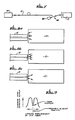
- a GRIN lens, indicated by reference numeral 10 and an associated fiber 12 are shown in Figure 1 as being aligned in such a manner that light from the fiber is incident perpendicularly on end surface 14 of the lens.
- the end surface 14 is the reference plane. If the surface 14 is mirrored, light will be reflected from it back along identical paths, and will be launched back into the fiber 12. If the reflective material on the surface 14 is not present, light will emerge from the lens 10 perpendicularly to the reference plane 14. When two such connector halves are butted together, they will therefore be in perfect alignment.
- Figure 2 shows the effect of an imperfect GRIN lens, indicated at 10'.
- the reference plane 14' is not perpendicular to the longitudinal axis of the cylindrical lens 10'.
- the fiber 12 is appropriately positioned to recapture light reflected from the surface 14' when coated with reflective material, light will still emerge from the uncoated surface 14' along paths that are perpendicular to the surface.
- the imperfect lens is coupled to a perfect one, such as the one in Figure 1, there will still be perfect alignment of the coupling halves. This is the basis for the alignment technique of the invention.
- Figure 3 shows one approach for aligning the fiber 12 with the lens 10 to ensure the desired perpendicular orientation of the emerging light beam with respect to the reference plane 14.
- the fiber 12 is passed through a detector apparatus 16, which includes a pair of lenses 18 and 20, a beam-splitting mirror 22 and a light detector 24.
- Light from a light source (not shown) emerges from the fiber 12 in the apparatus 16 and is collimated by the lens 18.
- the collimated beam impinges on the beam splitting mirror 22, and a transmitted portion of the light is focused by the other lens 20 into a continuing section of the fiber 12, which is positioned for launching the light into the lens 10.
- Reflected light from the lens 10 passes through the fiber 12, through the lens 20 and is reflected, in part, by the mirror 22.
- Another lens 26 is used to focus this reflected light into the light detector 24. Alignment of the fiber 12 and the lens 10 is achieved by moving the fiber laterally and axially with respect to the lens, as will be later described, until the detector output is maximized. Then the fiber 12 is permanently affixed to the lens 10 and the reflective coating on the lens is removed.
- Figure 5 also shows the assembly of lens and holder again, with the fiber 12 positioned in a fiber holder 34. There may be a quantity of index-matching cement between the end of the fiber 12 and the lens 10'. The fiber holder 34 is also cemented in place, as indicated at 36, after alignment with the lens 10'.
- Figure 6 is a fragmentary view of two coupled connector halves, including the connector parts 30 and the GRIN lenses 10. As indicated at 40, there is a space between the two connector halves. This may be filled by a precision spacer, or the two halves may be butted together, depending on the application of the connector and the fibers. Since lateral alignment of the connector halves is not extremely critical when GRIN lenses are used, appropriate alignment may be attained by means of matching dowel pins and holes, indicated at 42 and 43, respectively, in the connector parts 30. Ideally, the matching dowel pins and holes are arranged in such a manner that all of the connector halves are identical, and any two connector halves are, therefore, connectable.
- Figure 7 illustrates an alternative technique for the alignment of the fiber 12 with respect to the lens 10.
- the fiber 12 does not have to be interrupted between the light source 44 and the lens 10. Instead, the fiber 12 is slightly bent, as indicated at 46, and a detector 48 is employed to detect light emerging from the cladding of the fiber at the area of the bend 46.
- Figures 8a-8c illustrate the effect of lateral movement of the fiber 12 with respect to the lens 10. In Figure 8a, the fiber is much too lowto receive reflected light, and much of the reflected light misses the fiber altogether. Consequently, there is little reflected light launched into either the fiber core or the fiber cladding material.
- the fiber 12 is still slightly low, but some light is launched into the cladding, and is detectable at the detector 48.
- Figure 8c if the fiber 12 is correctly positioned with respect to the lens, almost all of the light reflected from the reference plane surface 14 will be launched into the fiber core, and very little will be launched into the cladding. Accordingly, as shown in the graph of Figure 9, lateral movement of the fiber 12 will produce a local minimum in the detected output from the cladding light detector 48. When this local minimum is detected, the fiber 12 can be cemented in place as in the first-described technique.
- FIG. 10a Another possible defect in GRIN lenses is that the focal point may not be exactly at the surface of the lens. This may necessitate axial alignment as well as lateral alignment of the fiber 12 with respect to the lens 10, as shown in Figures 10a, 10b and 11.
- Figure 10b the fiber 12 is too close to the lens 10, and much of the reflected light is launched into the cladding material.
- Figure 10b the fiber 12 is too far from the lens 10, and some light will still be launched into the cladding material.
- the optimum axial position shown in Figure 10c will result in the launching of light principally into the fiber core material, with very little going into the cladding.
- Figure 12 illustrates an alternative approach employing the method of the invention.
- This shows a GRIN lens 10' that is misaligned in its connector part 30.
- a temporary reference surface is provided by placing a plane mirror 50 over the connector part 30, and performing fiber alignment by one of the methods already described. This will ensure that light emerging from the connector half will be perpendicular to the surface of the connector part 30. Consequently, the connector half will be perfectly matched with another one formed by this or the previously described technique.
- the present invention represents a significant advance in the field of connectors for optical fibers.
- the invention provides a new technique for ensuring that connector halves will be matched and aligned, while minimizing connector losses and wastage of parts. It will also be appreciated that, although specific embodiments of the invention have been described in detail for purposes of illustration, various modifications may be made without departing from the scope of the invention. Accordingly, the invention is not to be limited except as by the appended claims.
- a method for aligning the fiber not requiring examination of the back-reflected light is shown in Figure 13.
- a lens coating 51 is modified so that part of the light is reflected back to the fiber 12, with the remainder being transmitted through a lens 52 to a scanning optical spectrometer or a scanning optical spectrum analyzer, indicated at 53.
- the fiber 12 misaligned with the GRIN lens 10 With the fiber 12 misaligned with the GRIN lens 10, the normal output of the laser is observed. Depending on the laser construction, one or more frequency components of a longitudinal mode will appear at the output of the spectrometer or analyzer 53.
- the fiber 12 is properly aligned with respect to the GRIN lens 10 so that the reflected light is fed back to the laser, the output spectral characteristic of the laser will change.
- the output will become very noisy, with spectral components changing rapidly, or the output optical spectrum will quiet down appreciably from its normal behaviour.
- the actual change that will be observed depends upon the phase stability of the light fed back to the laser. The observation of a changed optical output spectrum indicates that the fiber 12 is properly aligned with the GRIN rod lens 10.
- FIG. 14 An alternate method for aligning the fiber 12 to the GRIN lens 10 is shown in Figure 14.
- the coating 51 reflects part of the light back and transmits the remainder to lens 52 and detector 53.
- the electrical output of the detector 53 is amplified in an amplifier 54, and then transmitted to an electronic spectrum analyzer 55.
- the output of the spectrum analyzer 55 will only show the noise frequency spectrum of the laser source 44 and the detector 53 when the fiber 12 is misaligned to the GRIN lens 10.
- the laser spectral output will deviate from its normal output.
- the laser output may become noisy and appear in the spectrum analyzer as random noisy frequency components, or it may become less noisy if the light fed back to the laser remains locked in phase with the laser output, i.e., the fiber, the laser facet, and the external reflector may form a temperature-stable, external-coupled cavity to the laser.
- the deviation of the spectrum from normal will indicate that the fiber is properly aligned with the GRIN lens.
Description
- This invention relates generally to connectors for optical fibers, and more particularly, to methods for aligning single-mode and multimode optical fibers using graded refractive index (GRIN) lenses. The need for optical fiber connectors in optical fiber communication systems and other applications has long been apparent. Ideally connectors should present only a minimal loss in the fiber transmission medium.
- The principal causes of loss in all fiber optical connectors are angular and spatial misalignment. These alignment problems are particularly acute for single-mode fiber connectors, which have extremely small dimensional tolerances. In order to butt-couple two single-mode fibers with less than 0.1 decibel (dB) loss, the fiber cores must be aligned to a precision of less than one micron (1 X 10⁻⁶ meter).
- One approach to the alignment of single-mode fibers is to employ a graded refractive index lens on each side of the connector, and to butt the lenses together instead of the fibers themselves. Commercially available lenses for this purpose are sold underthe name SELFOC lenses. (SELFOC is a registered trademark of Nippon Sheet Glass Co.). These lenses will be referred to in this specification as graded refractive index lenses, or GRIN lenses.
- A quarter-pitch GRIN lens functions analogously to a collimating lens. The refractive index of the lens material varies across its cross section in such a manner as to expand a very small source of light, emerging from a single-mode fiber, into a much broader, parallel beam. If a second quarter-pitch GRIN lens is placed adjacent to the first one, the parallel beam is focused down to almost a point focus, for launching into a single-mode fiber in the second connector half. This approach has the advantage of greatly reducing the requirements for lateral alignment of the fibers, i.e., the required tolerance for lateral fiber alignment is greater. However, the use of connector lenses requires extreme precision of angular alignment. For a connector loss of 0.1 dB, the angular alignment tolerance is 0.0003 radians, or approximately one minute of arc (1/60 of a degree). Therefore, the GRIN lens connector approach trades dimensional alignment tolerance for angular alignment tolerance, and there is, therefore, a need for an accurate and convenient method of angular alignment of the connector lenses.
- One cannot rely on precision manufacture of the GRIN lenses, since not all such lenses are perfect plane cylinders, and losses of part wastage will inevitably result. In the past, techniques for assuring precision in the connector halves have relied on there being a near-perfect "master" parallel beam, generated either from a perfect connector half or from a separate source. The procedure typically used is to align and orient each manufactured connector half with the parallel beam. This may not always be possible for some lens components, and can still lead to wastage. The fiber is then positioned and attached to the lens, and in theory any two connector halves that have been matched to the master parallel beam will be perfectly matched to each other.
- Unfortunately, these prior-art techniques have not always worked in practice, and there is a need for alternative approach to angular alignment of GRIN lens connector halves. The present invention is directed to this end.
- The present invention resides in a novel method for alignment of lens-type optical fiber connectors. Briefly, and in general terms, the steps of the method include securing each lens in a holder with one of its end faces exposed, forming a common reference plane by grinding and polishing the exposed end face of the lens together with the adjacent surface of the holder, and positioning an optical fiber at the other end face of the lens in such a manner that light rays from the fiber have a perpendicular angle of incidence with the reference plane.
- Any two connector halves made by this method will then be perfectly angularly aligned if their reference planes are butted together or placed in a parallel relationship. Even if one of the lenses is not perfectly cylindrical, and has an end face not perpendicular to its axis, the alignment technique of the invention will ensure that light rays from the fiber will be incident perpendicularly on the reference plane, which is the end face of the lens. So long as the mating lens is similarly aligned, the two halves will be perfectly matched, even though one of them may be imperfect from a manufacturing standpoint. No standard connector or master parallel beam is required, and the method results in a minimum wastage of components, while still ensuring that any two connector halves will have near perfect angular alignment.
- Lateral alignment of the connector halves can be achieved by any conventional technique, such as by means of dowel pins and corresponding holes in the lens holders. The halves may be butted together or spaced apart by a precision shim, depending on the particular application.
- Any of several alternative approaches may be used to position the fiber with respect to the lens. In one approach, the positioning step includes coating the reference plane with a reflective material, launching light into the fiber, measuring the intensity of light reflected back along the fiber by the reflective coating, and moving the fiber with respect to the lens until the intensity of light found in the measuring step is at a maximum. More specifically, the step of measuring the reflected light intensity includes interposing a semi-reflective mirror in the reflected beam, and detecting the intensity of the reflected beam, wherein the semi-reflective mirror transmits light in the forward direction toward the connector.
- This direct approach to measuring the intensity of the reflected light has the disadvantage that it requires that the optical fiber both between the source of light and the connector be interrupted by the semi-reflective mirror and a detector. An alternative approach that avoids this problem includes the steps of bending the fiber slightly, detecting light emanating from the fiber cladding material at the position of the bend, and moving the fiber with respect to the lens until a local minimum is detected by the detecting step, this being indicative maximum light reflection into the core of the fiber, and minimum reflection into the adjacent cladding material.
- In some instances, the lens will be slightly shorter than a true quarter-pitch lens, i.e., its focal point will not be exactly at the end face of the lens, but rather will be spaced out from the end face. Accordingly, the positioning step may include the steps of positioning the fiber laterally with respect to the lens, and positioning the fiber axially with respect to the lens.
- Proper alignment of the fiber to the GRIN lens can be accomplished by observing the change in the laser source spectrum as the light is reflected back or fed back to the laser. The laser output is observed by placing a partially reflecting, partially transmitting coating on the GRIN lens surface. The transmitted laser light is examined for a changed spectrum to indicate proper alignment of the fiber to the GRIN lens. An advantage of this method is that very long lengths of fiber may be attached to the connector.
- It will be appreciated from the foregoing that the present invention represents a significant advance in the field of optical fiber connectors. In particular, the invention provides an improved technique for angularly aligning GRIN lenses used as connecting elements for optical fibers, especially single-mode fibers having extremely small dimensions. Other aspects and advantages of the invention will become apparent from the following more detailed description, taken in conjunction with the accompanying drawings.
-
- Figure 1 is a schematic view of an optical fiber and a GRIN connector lens angularly aligned with the fiber to provide an output beam perpendicular to the lens surface;
- Figure 2 is a schematic view similar to Figure 1, but showing in imperfect GRIN lens;
- Figure 3 is a schematic diagram showing a technique for aligning a fiber to a GRIN lens;
- Figure 4 is a cross-sectional view of a GRIN lens and a lens holder prior to grinding and polishing a reference plane surface;
- Figure 5 is a cross-sectional view of GRIN lens and lens holder assembly used in the alignment technique of the invention;
- Figure 6 is a fragmentary cross-sectional view of a pair of connector halves formed in accordance with the invention;
- Figure 7 is a schematic view showing an alternative technique for alignment of a fiber and a GRIN lens assembly;
- Figures 8a-8c are schematic views illustrating the degree of reflection back into a fiber depending on the position of the fiber with respect to the lens, with Figure 8a showing the fiber much too low, Figure 8b showing the fiber slightly too low, and Figure 8c showing the fiber properly aligned;
- Figure 9 is a graph showing the detected ouput of light from the fiber cladding for various fiber lateral displacements;
- Figures 10a-10c are schematic views illustrating the degree of reflection of light back into the fiber cladding depending on the axial position of the fiber with respect to the lens;
- Figure 11 is a graph showing the output of a detector of light reflected into the cladding of the fiber for various axial displacements of the fiber;
- Figure 12 is a schematic diagram showing an alternative technique for aligning a fiber in a connector having a misaligned GRIN lens;
- Figures 13 and 14 are schematic views illustrating an alternative technique for alignment of a fiber and a GRIN lens assembly.
- As shown in the drawings for purposes of illustration, the present invention is concerned with techniques for the fabrication and alignment of graduated refractive index (GRIN) lenses and optical fibers, for use in optical fiber connectors. As discussed above, the production of perfectly matched lens-type fiber connectors has posed practical difficulties, especially for very small single-mode fibers.
- In accordance with the invention, each connector half is made by first forming a reference plane that will be perpendicular to light emerging from the connector half. If both connector halves are made in the same manner, there will be practically perfect angular alignment between the halves.
- This principle is shown diagrammatically in Figures 1 and 2. A GRIN lens, indicated by
reference numeral 10 and an associatedfiber 12 are shown in Figure 1 as being aligned in such a manner that light from the fiber is incident perpendicularly onend surface 14 of the lens. Theend surface 14 is the reference plane. If thesurface 14 is mirrored, light will be reflected from it back along identical paths, and will be launched back into thefiber 12. If the reflective material on thesurface 14 is not present, light will emerge from thelens 10 perpendicularly to thereference plane 14. When two such connector halves are butted together, they will therefore be in perfect alignment. - Figure 2 shows the effect of an imperfect GRIN lens, indicated at 10'. The reference plane 14' is not perpendicular to the longitudinal axis of the cylindrical lens 10'. However, if the
fiber 12 is appropriately positioned to recapture light reflected from the surface 14' when coated with reflective material, light will still emerge from the uncoated surface 14' along paths that are perpendicular to the surface. Thus, when the imperfect lens is coupled to a perfect one, such as the one in Figure 1, there will still be perfect alignment of the coupling halves. This is the basis for the alignment technique of the invention. - Figure 3 shows one approach for aligning the
fiber 12 with thelens 10 to ensure the desired perpendicular orientation of the emerging light beam with respect to thereference plane 14. Thefiber 12 is passed through adetector apparatus 16, which includes a pair oflenses mirror 22 and alight detector 24. Light from a light source (not shown) emerges from thefiber 12 in theapparatus 16 and is collimated by thelens 18. The collimated beam impinges on thebeam splitting mirror 22, and a transmitted portion of the light is focused by theother lens 20 into a continuing section of thefiber 12, which is positioned for launching the light into thelens 10. Reflected light from thelens 10 passes through thefiber 12, through thelens 20 and is reflected, in part, by themirror 22. Anotherlens 26 is used to focus this reflected light into thelight detector 24. Alignment of thefiber 12 and thelens 10 is achieved by moving the fiber laterally and axially with respect to the lens, as will be later described, until the detector output is maximized. Then thefiber 12 is permanently affixed to thelens 10 and the reflective coating on the lens is removed. - If a pair of connector halves are to be properly aligned and matched, it will be necessary to ensure that the reference plane of each connector half is properly aligned with the mechanical support coupling half. As shown in Figure 4, an imperfect lens 10' is imperfectly attached to a
connector part 30. Theconnector part 30 is also cylindrical, and has a central hole for installation of the lens 10'. In spite of the lens imperfections, the technique of the invention still results in perfect matching of connector halves. The lens 10' and the connector part orholder 30 are together subject to grinding and polishing on a plane surface, as indicated by the polishing and grindingsurface 32. Surface 30' of the holder and the surface 14' of the GRIN lens are rendered coplaner by the grinding and polishing onsurface 32. The resulting coplanar surface is indicated by 30" and 14" of Figure 5 and forms the reference plane for the connector. Figure 5 also shows the assembly of lens and holder again, with thefiber 12 positioned in afiber holder 34. There may be a quantity of index-matching cement between the end of thefiber 12 and the lens 10'. Thefiber holder 34 is also cemented in place, as indicated at 36, after alignment with the lens 10'. - Figure 6 is a fragmentary view of two coupled connector halves, including the
connector parts 30 and theGRIN lenses 10. As indicated at 40, there is a space between the two connector halves. This may be filled by a precision spacer, or the two halves may be butted together, depending on the application of the connector and the fibers. Since lateral alignment of the connector halves is not extremely critical when GRIN lenses are used, appropriate alignment may be attained by means of matching dowel pins and holes, indicated at 42 and 43, respectively, in theconnector parts 30. Ideally, the matching dowel pins and holes are arranged in such a manner that all of the connector halves are identical, and any two connector halves are, therefore, connectable. - Figure 7 illustrates an alternative technique for the alignment of the
fiber 12 with respect to thelens 10. In contrast to the technique using thedetector apparatus 16 shown in Figure 3, in this approach thefiber 12 does not have to be interrupted between the light source 44 and thelens 10. Instead, thefiber 12 is slightly bent, as indicated at 46, and adetector 48 is employed to detect light emerging from the cladding of the fiber at the area of thebend 46. Figures 8a-8c illustrate the effect of lateral movement of thefiber 12 with respect to thelens 10. In Figure 8a, the fiber is much too lowto receive reflected light, and much of the reflected light misses the fiber altogether. Consequently, there is little reflected light launched into either the fiber core or the fiber cladding material. In Figure 8b, thefiber 12 is still slightly low, but some light is launched into the cladding, and is detectable at thedetector 48. Finally, as shown in Figure 8c, if thefiber 12 is correctly positioned with respect to the lens, almost all of the light reflected from thereference plane surface 14 will be launched into the fiber core, and very little will be launched into the cladding. Accordingly, as shown in the graph of Figure 9, lateral movement of thefiber 12 will produce a local minimum in the detected output from thecladding light detector 48. When this local minimum is detected, thefiber 12 can be cemented in place as in the first-described technique. - Another possible defect in GRIN lenses is that the focal point may not be exactly at the surface of the lens. This may necessitate axial alignment as well as lateral alignment of the
fiber 12 with respect to thelens 10, as shown in Figures 10a, 10b and 11. In Figure 10a, thefiber 12 is too close to thelens 10, and much of the reflected light is launched into the cladding material. In Figure 10b, thefiber 12 is too far from thelens 10, and some light will still be launched into the cladding material. The optimum axial position shown in Figure 10c will result in the launching of light principally into the fiber core material, with very little going into the cladding. Thus, there will be another local minimum in the detector output, as shown in Figure 11, when thefiber 12 is optimally aligned with thelens 10 in terms of its axial position. - Figure 12 illustrates an alternative approach employing the method of the invention. This shows a GRIN lens 10' that is misaligned in its
connector part 30. Instead of grinding and polishing a common reference surface, a temporary reference surface is provided by placing aplane mirror 50 over theconnector part 30, and performing fiber alignment by one of the methods already described. This will ensure that light emerging from the connector half will be perpendicular to the surface of theconnector part 30. Consequently, the connector half will be perfectly matched with another one formed by this or the previously described technique. - It will be appreciated from the foregoing that the present invention represents a significant advance in the field of connectors for optical fibers. In particular, the invention provides a new technique for ensuring that connector halves will be matched and aligned, while minimizing connector losses and wastage of parts. It will also be appreciated that, although specific embodiments of the invention have been described in detail for purposes of illustration, various modifications may be made without departing from the scope of the invention. Accordingly, the invention is not to be limited except as by the appended claims.
- A method for aligning the fiber not requiring examination of the back-reflected light is shown in Figure 13. A
lens coating 51 is modified so that part of the light is reflected back to thefiber 12, with the remainder being transmitted through alens 52 to a scanning optical spectrometer or a scanning optical spectrum analyzer, indicated at 53. With thefiber 12 misaligned with theGRIN lens 10, the normal output of the laser is observed. Depending on the laser construction, one or more frequency components of a longitudinal mode will appear at the output of the spectrometer oranalyzer 53. When thefiber 12 is properly aligned with respect to theGRIN lens 10 so that the reflected light is fed back to the laser, the output spectral characteristic of the laser will change. The output will become very noisy, with spectral components changing rapidly, or the output optical spectrum will quiet down appreciably from its normal behaviour. The actual change that will be observed depends upon the phase stability of the light fed back to the laser. The observation of a changed optical output spectrum indicates that thefiber 12 is properly aligned with theGRIN rod lens 10. - An alternate method for aligning the
fiber 12 to theGRIN lens 10 is shown in Figure 14. Thecoating 51 reflects part of the light back and transmits the remainder tolens 52 anddetector 53. The electrical output of thedetector 53 is amplified in anamplifier 54, and then transmitted to anelectronic spectrum analyzer 55. The output of thespectrum analyzer 55 will only show the noise frequency spectrum of the laser source 44 and thedetector 53 when thefiber 12 is misaligned to theGRIN lens 10. When thefiber 12 is properly aligned so that the light is reflected or fed back to the laser 44, the laser spectral output will deviate from its normal output. The laser output may become noisy and appear in the spectrum analyzer as random noisy frequency components, or it may become less noisy if the light fed back to the laser remains locked in phase with the laser output, i.e., the fiber, the laser facet, and the external reflector may form a temperature-stable, external-coupled cavity to the laser. The deviation of the spectrum from normal will indicate that the fiber is properly aligned with the GRIN lens.
Claims (8)
the method further comprises after the step of positioning an optical fiber, the step of removing the plane mirror.
Applications Claiming Priority (2)
| Application Number | Priority Date | Filing Date | Title |
|---|---|---|---|
| US06/695,516 US4637683A (en) | 1985-01-28 | 1985-01-28 | Method for aligning optical fiber connectors |
| US695516 | 1985-01-28 |
Publications (3)
| Publication Number | Publication Date |
|---|---|
| EP0189966A2 EP0189966A2 (en) | 1986-08-06 |
| EP0189966A3 EP0189966A3 (en) | 1987-11-19 |
| EP0189966B1 true EP0189966B1 (en) | 1990-12-27 |
Family
ID=24793328
Family Applications (1)
| Application Number | Title | Priority Date | Filing Date |
|---|---|---|---|
| EP86300027A Expired - Lifetime EP0189966B1 (en) | 1985-01-28 | 1986-01-03 | Method for aligning optical fiber connectors |
Country Status (4)
| Country | Link |
|---|---|
| US (1) | US4637683A (en) |
| EP (1) | EP0189966B1 (en) |
| JP (1) | JP2517548B2 (en) |
| DE (1) | DE3676510D1 (en) |
Cited By (1)
| Publication number | Priority date | Publication date | Assignee | Title |
|---|---|---|---|---|
| WO2011159539A3 (en) * | 2010-06-14 | 2012-04-19 | Ipg Photonics Corporation | Fiber laser system configured to controllably align beam |
Families Citing this family (24)
| Publication number | Priority date | Publication date | Assignee | Title |
|---|---|---|---|---|
| DE3413667A1 (en) * | 1984-04-11 | 1985-10-17 | Siemens AG, 1000 Berlin und 8000 München | METHOD FOR ADJUSTING A COUPLING OPTICS PROVIDED AT THE END OF AN OPTICAL WAVE GUIDE TO A SEMICONDUCTOR LASER, AND DEVICE FOR CARRYING OUT THE METHOD |
| IT1222224B (en) * | 1988-03-25 | 1990-09-05 | Consiglio Nazionale Ricerche | SELF-PARKING OPTICAL SYSTEM FOR SPECTROPHOTOMETRY AND SIMILAR MEASUREMENTS, WITH FIBER OPTIC SENSORS |
| US4859021A (en) * | 1988-09-20 | 1989-08-22 | Hughes Aircraft Company | Hermetic feedthrough connector for fiber optic transmission |
| GB2230348A (en) * | 1989-04-08 | 1990-10-17 | Plessey Co Plc | Optical coupling through an image surface. |
| US5155549A (en) * | 1990-10-25 | 1992-10-13 | The Research Of State University Of New York | Method and apparatus for determining the physical properties of materials using dynamic light scattering techniques |
| DE19506675C2 (en) * | 1995-02-25 | 1999-08-19 | Schumacher Hamedat | Device for coupling light transmitted through a sample or reflected, scattered, emitted or re-emitted into a light guide |
| US5680492A (en) * | 1995-08-01 | 1997-10-21 | Cogent Light Technologies, Inc. | Singular fiber to bundle illumination with optical coupler |
| US6188472B1 (en) * | 1998-04-17 | 2001-02-13 | Iolon, Inc. | System and method for direct measurement of alignment error in a fiber coupler |
| CA2279714A1 (en) * | 1999-08-04 | 2001-02-04 | Jds Fitel Inc. | Method and system for measurement of a characteristic of lens |
| US6454465B1 (en) * | 2000-03-31 | 2002-09-24 | Corning Incorporated | Method of making an optical fiber collimating device |
| US6813420B1 (en) * | 2000-09-21 | 2004-11-02 | Axsun Technologies, Inc. | Process and system for tunable filter optical train alignment |
| US6370299B1 (en) | 2000-09-27 | 2002-04-09 | The Boeing Company | Fiber optic collimation apparatus and associated method |
| US6433924B1 (en) * | 2000-11-14 | 2002-08-13 | Optical Coating Laboratory, Inc. | Wavelength-selective optical amplifier |
| US7212745B2 (en) * | 2000-11-30 | 2007-05-01 | Matsushita Electric Industrial Co., Ltd. | Optical transmission system |
| US6587618B2 (en) | 2001-03-16 | 2003-07-01 | Corning Incorporated | Collimator array and method and system for aligning optical fibers to a lens array |
| US6404955B1 (en) * | 2001-07-03 | 2002-06-11 | Corning, Incorporated | System and method for fabricating arrayed optical fiber collimators |
| US20070236384A1 (en) * | 2006-02-12 | 2007-10-11 | Gennadii Ivtsenkov | Cost-effective friend-or-foe (IFF) combat infrared alert and identification system (CID) |
| WO2008109978A1 (en) * | 2007-03-13 | 2008-09-18 | Gennadii Ivtsenkov | Cost-effective friend-or-foe (iff) battlefield infrared alarm and identification system |
| DE102007051294B4 (en) * | 2007-07-20 | 2012-03-22 | Lasos Lasertechnik Gmbh | Optical connector for optical fibers |
| US9102563B2 (en) * | 2009-10-15 | 2015-08-11 | Greg S. Laughlin | Environmentally rugged free-space fiber waveguide connector and method of manufacture thereof |
| US10007062B2 (en) * | 2013-05-03 | 2018-06-26 | Molex, Llc | Optical fiber assembly |
| JP6725421B2 (en) | 2014-01-31 | 2020-07-15 | ザ ジェネラル ホスピタル コーポレイション | Small endoscope using nanoimprint lithography |
| US9869820B2 (en) * | 2015-12-09 | 2018-01-16 | Canon U.S.A, Inc. | Optical probe, light intensity detection, imaging method and system |
| CN114112942A (en) * | 2021-12-17 | 2022-03-01 | 中国电子科技集团公司第十三研究所 | Optical fiber corner cut direction alignment equipment and alignment method |
Family Cites Families (15)
| Publication number | Priority date | Publication date | Assignee | Title |
|---|---|---|---|---|
| US3829195A (en) * | 1973-06-25 | 1974-08-13 | Bell Telephone Labor Inc | Optical couplers |
| JPS5133565U (en) * | 1974-09-02 | 1976-03-12 | ||
| DE2456293B2 (en) * | 1974-11-28 | 1980-12-04 | Felten & Guilleaume Carlswerk Ag, 5000 Koeln | Method and device for determining the location of faults in optical fibers or optical fiber cables |
| US4290667A (en) * | 1976-02-03 | 1981-09-22 | International Standard Electric Corporation | Optical fibre terminations and connectors |
| DE2841133A1 (en) * | 1978-09-21 | 1980-04-03 | Siemens Ag | Tapping element for optical fibre - follows curved section to receive light emerging from side without breaking into it |
| NL7905610A (en) * | 1979-07-19 | 1981-01-21 | Philips Nv | REMOVABLE COUPLING FOR PAIRLY COUPLING OF LIGHT-CONDUCTING FIBERS. |
| JPS56159604A (en) * | 1980-05-14 | 1981-12-09 | Toshiba Corp | Total reflection terminator of optical fiber |
| CA1193477A (en) * | 1981-02-24 | 1985-09-17 | Tetsuya Yamasaki | Fixing substrate for optical fibers |
| JPS58158619A (en) * | 1982-03-15 | 1983-09-20 | Toshiba Corp | Adjusting method of photosensor |
| JPS58162919A (en) * | 1982-03-23 | 1983-09-27 | Nippon Telegr & Teleph Corp <Ntt> | Connecting method of optical fiber |
| JPS593408A (en) * | 1982-06-29 | 1984-01-10 | Nippon Sheet Glass Co Ltd | Terminal for optical fiber and its production |
| JPS599615A (en) * | 1982-07-07 | 1984-01-19 | Nippon Sheet Glass Co Ltd | Optical fiber connector |
| JPS5915107A (en) * | 1982-07-14 | 1984-01-26 | 穐山 司朗 | Snow melting apparatus utilizing induction heating |
| US4509827A (en) * | 1983-02-02 | 1985-04-09 | The United States Of America As Represented By The United States Secretary Of The Navy | Reproducible standard for aligning fiber optic connectors which employ graded refractive index rod lenses |
| JPS59229515A (en) * | 1983-06-13 | 1984-12-24 | Nippon Sheet Glass Co Ltd | Method for aligning optical axis of distributed index lens and optical fiber |
-
1985
- 1985-01-28 US US06/695,516 patent/US4637683A/en not_active Expired - Lifetime
-
1986
- 1986-01-03 EP EP86300027A patent/EP0189966B1/en not_active Expired - Lifetime
- 1986-01-03 DE DE8686300027T patent/DE3676510D1/en not_active Expired - Lifetime
- 1986-01-23 JP JP61012975A patent/JP2517548B2/en not_active Expired - Fee Related
Cited By (2)
| Publication number | Priority date | Publication date | Assignee | Title |
|---|---|---|---|---|
| WO2011159539A3 (en) * | 2010-06-14 | 2012-04-19 | Ipg Photonics Corporation | Fiber laser system configured to controllably align beam |
| US8254417B2 (en) | 2010-06-14 | 2012-08-28 | Ipg Photonics Corporation | Fiber laser system with controllably alignable optical components thereof |
Also Published As
| Publication number | Publication date |
|---|---|
| EP0189966A3 (en) | 1987-11-19 |
| JP2517548B2 (en) | 1996-07-24 |
| US4637683A (en) | 1987-01-20 |
| DE3676510D1 (en) | 1991-02-07 |
| EP0189966A2 (en) | 1986-08-06 |
| JPS61215504A (en) | 1986-09-25 |
Similar Documents
| Publication | Publication Date | Title |
|---|---|---|
| EP0189966B1 (en) | Method for aligning optical fiber connectors | |
| US7474822B2 (en) | Optical fiber collimator | |
| US4509827A (en) | Reproducible standard for aligning fiber optic connectors which employ graded refractive index rod lenses | |
| JP4215635B2 (en) | Method for adjusting the components of an optical fiber collimator having an array structure | |
| JP3852709B2 (en) | Optical power monitor and manufacturing method thereof | |
| JP3124465B2 (en) | Optical coupler | |
| US10816735B2 (en) | Lensed connector ferrule assemblies and methods of fabricating the same | |
| EP0190146B1 (en) | Plural-channel optical rotary joint | |
| US4439005A (en) | Branching element for optical waveguides | |
| TW200426418A (en) | Optical collimator structure | |
| EP3133427A1 (en) | Expanded beam connector with discrete alignment assembly | |
| US5009482A (en) | Method and apparatus for fabricating a pigtailed lens assembly | |
| EP0695961B1 (en) | Method of manufacturing fiber-optic collimators | |
| JPS5927884B2 (en) | How to connect optical fiber | |
| US4022533A (en) | Laser alignment apparatus and method with an alignment mirror | |
| JPH0836119A (en) | Manufacture of low-loss collimator couple | |
| JPH0815564A (en) | Optical fiber connecting system and its connecting module | |
| JP2001100122A (en) | Variable branching ratio type optical branching coupler and variable connection ratio type optical coupler | |
| US20060239611A1 (en) | Optical collimator | |
| US8238701B2 (en) | Optical connector | |
| JPH0442803Y2 (en) | ||
| JP4112126B2 (en) | Optical system | |
| JPH06129838A (en) | Angle parameter measuring method for optical fiber having slanting end and its device | |
| JP3182078B2 (en) | Measuring method of the deviation angle between the angle direction of the ferrule end face and the wavefront direction of the optical fiber or the ferrule hole alignment direction | |
| JP3949137B2 (en) | Optical fiber terminal, manufacturing method thereof, optical coupler and optical component |
Legal Events
| Date | Code | Title | Description |
|---|---|---|---|
| PUAI | Public reference made under article 153(3) epc to a published international application that has entered the european phase |
Free format text: ORIGINAL CODE: 0009012 |
|
| AK | Designated contracting states |
Kind code of ref document: A2 Designated state(s): DE FR GB NL SE |
|
| 17P | Request for examination filed |
Effective date: 19870205 |
|
| PUAL | Search report despatched |
Free format text: ORIGINAL CODE: 0009013 |
|
| AK | Designated contracting states |
Kind code of ref document: A3 Designated state(s): DE FR GB NL SE |
|
| 17Q | First examination report despatched |
Effective date: 19891024 |
|
| GRAA | (expected) grant |
Free format text: ORIGINAL CODE: 0009210 |
|
| AK | Designated contracting states |
Kind code of ref document: B1 Designated state(s): DE FR GB NL SE |
|
| PG25 | Lapsed in a contracting state [announced via postgrant information from national office to epo] |
Ref country code: SE Free format text: LAPSE BECAUSE OF FAILURE TO SUBMIT A TRANSLATION OF THE DESCRIPTION OR TO PAY THE FEE WITHIN THE PRESCRIBED TIME-LIMIT Effective date: 19901227 Ref country code: NL Effective date: 19901227 |
|
| PGFP | Annual fee paid to national office [announced via postgrant information from national office to epo] |
Ref country code: NL Payment date: 19910131 Year of fee payment: 6 |
|
| REF | Corresponds to: |
Ref document number: 3676510 Country of ref document: DE Date of ref document: 19910207 |
|
| ET | Fr: translation filed | ||
| NLV1 | Nl: lapsed or annulled due to failure to fulfill the requirements of art. 29p and 29m of the patents act | ||
| PLBE | No opposition filed within time limit |
Free format text: ORIGINAL CODE: 0009261 |
|
| STAA | Information on the status of an ep patent application or granted ep patent |
Free format text: STATUS: NO OPPOSITION FILED WITHIN TIME LIMIT |
|
| 26N | No opposition filed | ||
| PGFP | Annual fee paid to national office [announced via postgrant information from national office to epo] |
Ref country code: SE Payment date: 19911230 Year of fee payment: 7 |
|
| REG | Reference to a national code |
Ref country code: GB Ref legal event code: IF02 |
|
| PGFP | Annual fee paid to national office [announced via postgrant information from national office to epo] |
Ref country code: GB Payment date: 20021210 Year of fee payment: 18 |
|
| PGFP | Annual fee paid to national office [announced via postgrant information from national office to epo] |
Ref country code: FR Payment date: 20030107 Year of fee payment: 18 |
|
| PGFP | Annual fee paid to national office [announced via postgrant information from national office to epo] |
Ref country code: DE Payment date: 20030131 Year of fee payment: 18 |
|
| REG | Reference to a national code |
Ref country code: GB Ref legal event code: 732E |
|
| PG25 | Lapsed in a contracting state [announced via postgrant information from national office to epo] |
Ref country code: GB Free format text: LAPSE BECAUSE OF NON-PAYMENT OF DUE FEES Effective date: 20040103 |
|
| PG25 | Lapsed in a contracting state [announced via postgrant information from national office to epo] |
Ref country code: DE Free format text: LAPSE BECAUSE OF NON-PAYMENT OF DUE FEES Effective date: 20040803 |
|
| GBPC | Gb: european patent ceased through non-payment of renewal fee |
Effective date: 20040103 |
|
| PG25 | Lapsed in a contracting state [announced via postgrant information from national office to epo] |
Ref country code: FR Free format text: LAPSE BECAUSE OF NON-PAYMENT OF DUE FEES Effective date: 20040930 |
|
| REG | Reference to a national code |
Ref country code: FR Ref legal event code: ST |
|
| REG | Reference to a national code |
Ref country code: FR Ref legal event code: TP Ref country code: FR Ref legal event code: CD |