EP2363685B1 - Positioning device with confocal Fabry-Perot interferometer - Google Patents
Positioning device with confocal Fabry-Perot interferometer Download PDFInfo
- Publication number
- EP2363685B1 EP2363685B1 EP10153054.1A EP10153054A EP2363685B1 EP 2363685 B1 EP2363685 B1 EP 2363685B1 EP 10153054 A EP10153054 A EP 10153054A EP 2363685 B1 EP2363685 B1 EP 2363685B1
- Authority
- EP
- European Patent Office
- Prior art keywords
- fabry
- perot interferometer
- mirror
- resonator
- resonator mirror
- Prior art date
- Legal status (The legal status is an assumption and is not a legal conclusion. Google has not performed a legal analysis and makes no representation as to the accuracy of the status listed.)
- Active
Links
Images


Classifications
-
- G—PHYSICS
- G01—MEASURING; TESTING
- G01B—MEASURING LENGTH, THICKNESS OR SIMILAR LINEAR DIMENSIONS; MEASURING ANGLES; MEASURING AREAS; MEASURING IRREGULARITIES OF SURFACES OR CONTOURS
- G01B9/00—Measuring instruments characterised by the use of optical techniques
- G01B9/02—Interferometers
- G01B9/02041—Interferometers characterised by particular imaging or detection techniques
- G01B9/02042—Confocal imaging
-
- G—PHYSICS
- G01—MEASURING; TESTING
- G01B—MEASURING LENGTH, THICKNESS OR SIMILAR LINEAR DIMENSIONS; MEASURING ANGLES; MEASURING AREAS; MEASURING IRREGULARITIES OF SURFACES OR CONTOURS
- G01B11/00—Measuring arrangements characterised by the use of optical techniques
- G01B11/002—Measuring arrangements characterised by the use of optical techniques for measuring two or more coordinates
-
- G—PHYSICS
- G01—MEASURING; TESTING
- G01B—MEASURING LENGTH, THICKNESS OR SIMILAR LINEAR DIMENSIONS; MEASURING ANGLES; MEASURING AREAS; MEASURING IRREGULARITIES OF SURFACES OR CONTOURS
- G01B9/00—Measuring instruments characterised by the use of optical techniques
- G01B9/02—Interferometers
- G01B9/02055—Reduction or prevention of errors; Testing; Calibration
- G01B9/02056—Passive reduction of errors
- G01B9/02061—Reduction or prevention of effects of tilts or misalignment
-
- G—PHYSICS
- G01—MEASURING; TESTING
- G01B—MEASURING LENGTH, THICKNESS OR SIMILAR LINEAR DIMENSIONS; MEASURING ANGLES; MEASURING AREAS; MEASURING IRREGULARITIES OF SURFACES OR CONTOURS
- G01B9/00—Measuring instruments characterised by the use of optical techniques
- G01B9/02—Interferometers
- G01B9/02055—Reduction or prevention of errors; Testing; Calibration
- G01B9/02075—Reduction or prevention of errors; Testing; Calibration of particular errors
- G01B9/02078—Caused by ambiguity
- G01B9/02079—Quadrature detection, i.e. detecting relatively phase-shifted signals
- G01B9/02081—Quadrature detection, i.e. detecting relatively phase-shifted signals simultaneous quadrature detection, e.g. by spatial phase shifting
-
- G—PHYSICS
- G01—MEASURING; TESTING
- G01B—MEASURING LENGTH, THICKNESS OR SIMILAR LINEAR DIMENSIONS; MEASURING ANGLES; MEASURING AREAS; MEASURING IRREGULARITIES OF SURFACES OR CONTOURS
- G01B2290/00—Aspects of interferometers not specifically covered by any group under G01B9/02
- G01B2290/25—Fabry-Perot in interferometer, e.g. etalon, cavity
-
- G—PHYSICS
- G01—MEASURING; TESTING
- G01B—MEASURING LENGTH, THICKNESS OR SIMILAR LINEAR DIMENSIONS; MEASURING ANGLES; MEASURING AREAS; MEASURING IRREGULARITIES OF SURFACES OR CONTOURS
- G01B2290/00—Aspects of interferometers not specifically covered by any group under G01B9/02
- G01B2290/45—Multiple detectors for detecting interferometer signals
Definitions
- the invention relates to a device and a method for position detection and an arrangement comprising a positioner and a device for position detection.
- EP 2 045 572 A1 is a device for position detection which uses a Fabry-Perot interferometer as a detector head.
- the interference pattern generated in the Fabry-Perot interferometer is detected by means of a detector.
- An evaluation circuit performs a quadrature evaluation of the detector signal generated by the detector.
- the device allows a very accurate position determination or path length measurement, but high demands are placed on the mirror parallelism of the Fabry-Perot interferometer resonator, which can increase the construction costs and assembly costs, limit the application area and limit the measuring range of the device.
- the publication WO 83/03010 A1 discloses a device for detecting position with a confocal Fabry-Perot interferometer.
- a confocal Fabry-Perot interferometer according to the document WO 83/03010 A1 a high measuring sensitivity and a stability against the adjustment achieved, see page 2, lines 8 - 13.
- the publication DE 40 18 998 A1 discloses a non-confocal Fabry-Perot interferometer for detecting the position of a mirrored membrane. Furthermore, it is stated in the document that an optical system for focusing and / or folding the light rays reflected back and forth in the Fabry-Perot resonator can be arranged in the Fabry-Perot resonator (column 5, lines 4-6, column 11, lines 59) - 63, column 19, lines 31-34).
- An object of the invention is therefore to be seen to provide a device and a method for position detection, which is cost-effective and can be used in a variety of applications.
- the device should be able to be integrated into a positioner and allow the positioning path generated by the positioner to be monitored.
- the device for position detection on a confocal Fabry-Perot interferometer causes the light beam circulating in the resonator of the Fabry-Perot interferometer to be independent of adjustment errors of the mirrors arranged in the beam path to a known point, typically the entry point of a light bundle fed into the Fabry-Perot interferometer (resonator) is, is focused.
- a known point typically the entry point of a light bundle fed into the Fabry-Perot interferometer (resonator) is, is focused.
- This allows a simple and inexpensive construction of the device can be achieved and there is a low adjustment effort when installing the device in their installation environment, e.g. a positioner, on.
- the device according to the invention can be used in installation environments with unfavorable conditions (vibrations, low installation space), whereby a large number of applications for the device according to the invention are made possible in the first place.
- the confocal Fabry-Perot interferometer comprises a first and a second resonator mirror and a folding mirror arranged in the beam path between the first and the second resonator mirror.
- the folding mirror is coupled to the object whose position is to be determined and allows a Autofocus, which is independent of the length of the beam path in the Fabry-Perot interferometer.
- the confocal Fabry-Perot interferometer comprises a collimator arranged in the beam path between the first and second resonator mirrors.
- the collimator serves to focus or focus the beam path in the Fabry-Perot interferometer and, in conjunction with the folding mirror, effects autofocusing, which is independent of the length of the beam path in the Fabry-Perot interferometer.
- One or more collimators may also be provided in a confused Fabry-Perot interferometer without a folding mirror.
- the first and the second resonator mirrors are arranged fixed relative to one another in a positionally fixed manner.
- a compact and robust Fabry-Perot interferometer can be realized.
- the finesse of the Fabry-Perot interferometer is less than 1.0, in particular less than 0.5.
- the interference contrast of the interference pattern generated by the Fabry-Perot interferometer behaves approximately according to a cosine function depending on the object position.
- the evaluation of a measurement signal obtained by detection of the interference pattern in an evaluation circuit is substantially facilitated and, in particular, the evaluation accuracy is increased.
- the reflectance of the first resonator mirror and the reflectance of the second resonator mirror are approximately equal. This allows a high contrast of the interference pattern and thus a high accuracy of the position determination.
- the second resonator mirror is preferably realized by an end face of an optical part arranged laterally next to the first resonator mirror.
- the first resonator mirror may be the exit surface of a core of a light guide
- the second resonator mirror may be the jacket of the light guide laterally surrounding the core.
- the device according to the invention measures a distance measurement or position determination over a measuring range of more than 10 -4 m, in particular more than 10 -3 m and, without further measures, more than 10 . 2 m can perform.
- the resolution can be over the entire measuring path in the sub-nanometer range.
- a method for position detection is defined by claim 14.
- the inventive method can be carried out in the manner already described by a structurally simple design Fabry-Perot interferometer and requires a relatively low installation and adjustment costs.
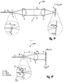
- Fig. 1 illustrates the basic structure of a Fabry-Perot interferometer 10.
- This comprises a first resonator mirror 1 and a second resonator mirror 2, which together form an optical resonator.
- the first resonator mirror 1 is partially transparent and reflects part of the incident light 3 back. The other part passes through the resonator, is reflected at the second resonator mirror 2 and partly transmitted by the first resonator mirror 1.
- the light 4 reflected by the Fabry-Perot interferometer 10 thus results from a superimposition of the light reflected by the resonator mirror 1 with the light reflected by the resonator mirror 2.
- the mirror spacing or a change in the mirror spacing can be determined.
- a displacement of, for example, the second resonator mirror 2 from the point A to the point B thus causes a change in the intensity I R of the reflected light 4, as in the lower part of the Fig. 1 is shown. Since the wavelength ⁇ of the measuring light is known, the displacement of the resonator mirror 2 from A to B and thus the change in the length of the resonator of the Fabry-Perot interferometer can be determined from a measurement of the intensity I R of the reflected light.
- Fig. 2 shows a Fabry-Perot interferometer 20, which is based on the Fig. 1 explained principle is based.
- the measuring light is guided by means of a light guide 5 to the Fabry-Perot interferometer 20.
- the light guide 5 comprises a core 5a and a jacket 5b surrounding the core 5a.
- the cladding 5b has a (slightly) smaller refractive index than the core 5a.
- the measuring light 3 emerges from the polished end of the light guide 5 and is collimated by a collimator 6 into a parallel light beam 3.
- the parallel light beam 3 is incident on the second resonator mirror 2, is reflected back from this to the collimator 6 and focused by the collimator 6 and returned to the light guide 5.
- the lens plane of the collimator 6 is for this purpose at a distance f (focal length of the collimator 6) from the exit surface of the light guide fifth
- a Fabry-Perot interferometer 20 is the first resonator mirror. 1 formed by the light exit surface of the core 5a.
- the resonator of the Fabry-Perot interferometer is thus located between the light exit surface of the core 5a and the second resonator mirror 2, which is position-variable coupled to the object (not shown).
- the Fabry-Perot interferometer 20 only functions if the light reflected back from the second resonator mirror 2 is coupled back into the core 5a of the light guide 5 after being focused by the collimator 6. The prerequisite for this is that the second resonator mirror 2 is aligned with high accuracy perpendicular to the optical axis of the Fabry-Perot interferometer 20 and this alignment is maintained even with a movement of the second resonator mirror 2. This condition is structurally difficult to meet during object movement and in any case requires a high adjustment effort. This can be seen by a simple example calculation: The diameter of the core 5a at the exit surface (i.e., the diameter of the first resonator mirror 1) is referred to as MFD (Mode Field Diameter).
- MFD Mode Field Diameter
- the tilt ⁇ of the second resonator mirror 2 with respect to its ideal position must satisfy the condition ⁇ MFD / (4f), so that the light reflected from the second resonator mirror 2 is returned to the core 5a and thus interference patterns in the reflected light 4 can occur.
- ⁇ is 0.25 mRAD.
- the second resonator mirror 2 must be mounted on an expensive precision mount and a perfectly tilt-free translational movement of the second resonator mirror 2 must be ensured. This is not possible in practice or only with great effort.
- contrast R Max - R min R Max expressed.
- the interferometer is functional only in a very narrow permitted range of the tilt angle ⁇ .
- a confocal Fabry-Perot interferometer is used to determine this Fig. 3 explained adjustment problem of a non-confocal Fabry-Perot interferometer 20 overcome.
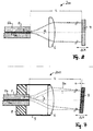
- Fig. 4 shows a non-inventive confocal Fabry-Perot interferometer 100 for position determination. The same or similar parts as in the preceding figures are designated by the same reference numerals. This in Fig. 4 shown Fabry-Perot interferometer 100 differs from that in Fig.
- Fabry-Perot interferometer 20 represented Fabry-Perot interferometer 20 characterized in that in the resonator, a second collimator 6 'is housed, which focuses the light beam generated by the first collimator 6 3 on the second resonator mirror 2. Even if this, as in Fig. 4 is shown tilted, the light reflected by the second resonator mirror 2 3 'after passing through the two collimators 6' and 6 is reflected exactly back into the core 5a of the light guide 5.
- the second collimator 6 ' may have the same focal length f as the first collimator 6.
- the confocal optics 6, 6 'thus causes the in Fig. 2 in connection with a Spiegelverkippung described problems (high equipment costs, difficult adjustment) omitted.
- the Fabry-Perot interferometer 100 has a relatively small measuring range ⁇ x max , since this is limited by the depth of focus of the focus on the second resonator mirror 2. In practice, the measuring range is limited to, for example, about 40 ⁇ m. Larger displacement paths are therefore with the in Fig. 4 Fabry-Perot interferometer 100 can not be detected.
- Fig. 5 shows an inventive embodiment of a confocal Fabry-Perot interferometer 200, with which a measuring range .DELTA.x max can be achieved, which is not limited by the focal length f, but only by structural conditions (and therefore can be very large).
- the Fabry-Perot interferometer 200 is based on the idea of the beam path of the in Fig. 4 shown Fabry-Perot interferometer 100 at the mid-perpendicular Y between the collimators 6 and 6 'too wrinkles.
- the folding causes focal points of the confocal optics always occur on stationary (stationary) mirrors, whereby the basis of Fig. 4 explained range limitation of the Fabry-Perot interferometer 100 is overcome.
- the confocal property of the interferometer optics is preserved, ie the in Fig. 5 shown Fabry-Perot interferometer is a confocal interferometer 200.
- the folding of the beam path 3, 3 'of in Fig. 4 shown confocal optics is achieved in the Fabry-Perot interferometer 200 by a flat folding mirror 7.
- the folding mirror 7 is coupled in terms of movement with the object (not shown) whose position or position change is to be determined.
- the beam path 3 of the light emerging from the light guide 5 and focused by the collimator 6 is converted by the folding mirror 7 into the beam path 3 c.
- a tilting ⁇ of the folding mirror with respect to the perpendicular to the optical axis of the Fabry-Perot interferometer 200 is assumed.
- the light beam 3c reflected by the folding mirror 7 passes through the collimator 6 (which now corresponds to the collimator 6 'in FIG Fig.
- Fig. 5 makes it clear that the confocal property of the interferometer optics is independent of the tilt angle ⁇ as long as the pixel B still strikes the end face of the light guide 5.
- the diameter of the optical waveguide 5 (ie its cladding diameter) is denoted by D.
- D the diameter of the optical waveguide 5 (ie its cladding diameter) is denoted by D.
- the condition for the maximum allowable tilt angle ⁇ is ⁇ ⁇ D / (4f).
- f 10 mm, e.g. ⁇ ⁇ 3.125 mRAD.
- the condition R 1 ⁇ R 2 should apply.
- the folding mirror 7 then preferably has a high reflectance R c greater than 0.9, in particular greater than 0.95 or R c ⁇ 1.0 (ie near 100%) in order to minimize the light intensity in the two reflections influence.
- the confocal Fabry-Perot interferometer 200 Due to the high reflectance R c of the folding mirror 7, the confocal Fabry-Perot interferometer 200 no longer functions for ⁇ ⁇ MFD / 2, ie for the case where the pixel B is as in FIG Fig. 2 falls on the exit surface of the core 5a. Because in this case, the folding mirror 7 to the second resonator mirror, whereby the contrast of the interference pattern in the reflected light 4 according to equation (1) assumes a very low value near zero.
- Fig. 6 illustrates the contrast of the interference pattern in the reflected light 4 as a function of the tilt angle ⁇ for the confocal Fabry-Perot interferometer 200.
- the curve is inverse to that in FIG Fig. 3 shown curve.
- the folding mirror 7 must be tilted or "misaligned" with a tilt angle ⁇ > MFD / (4f) compared to its "normal position” , This "misalignment condition" after Fig. 6 is much easier to assure in practice than the adjustment condition Fig. 3 ,
- Fabry-Perot interferometer 20 can be converted by simple measures into the confocal Fabry-Perot interferometer 200: For example, only the resonator mirror 2 with low reflectance R 2 is to be replaced by the folding mirror 7 with preferably high reflectance R c and the already difficult axis adjustment to avoid this mirror. By doubling the optical path length in the interferometer resonator, an additional increase in accuracy by a factor of 2 is achieved. Otherwise, to avoid repetition to the description Fig. 2 Referenced.
- FIGS. 7 and 8 show the beam path of the Fabry-Perot interferometer 200 at different tilt angles in greater detail.
- the working area is shown with ⁇ > MFD / 2.
- the pixel B is outside the core 5a.
- the beam path is shown for a very small tilt ⁇ , in which the pixel B falls within the region of the core 5a, ie ⁇ ⁇ MFD / 2. In this case, a significant loss of contrast is observed, see Fig. 6 ,
- the end of the light guide 5 via a fiber ferrule or a holder 8 and a housing 9 can be fixedly connected to the collimator 6.
- the distance L between the end of the optical fiber 5 and the folding mirror 7 is limited only by design limitations, and can be increased almost arbitrarily at a given angle ⁇ by increasing the diameter of the collimator 6 and / or by increasing the diameter D of the jacket 5b become. Without further measures, measuring ranges of more than 1 cm or even 10 cm and more are possible. In this case, during the translational movement of the folding mirror 7, a change in the tilt angle ⁇ , for example due to vibrations or the translational motion itself, can be tolerated as long as the condition MFD / 2 ⁇ ⁇ D / 2 remains satisfied. This allows use of the confocal Fabry-Perot interferometer 200 in a variety of applications.
- FIGS. 9 and 10 show further variations of the Fabry-Perot interferometer 200.
- the fiber ferrule 8 and the optional housing 9 are in the FIGS. 9 and 10 not shown.
- the effective diameter D of the jacket 5b can be increased by an optical part, eg a ring piece 5c.
- the optical ring piece 5c may be made of the same material as the cladding 5b and have a ring surface coplanar with the end face of the cladding 5b.
- the end surface of the second resonator mirror 2 (ie here of the shell 5b as well as the adjoining surface of the ring piece 5c, if present) may be provided with a spherical shape or recess. This improves the optical imaging accuracy of the confocal optics and thus the optical properties of the Fabry-Perot interferometer 200.
- Both resonator mirrors 1, 2 can also have a curved shape.
- a further variant of the confocal Fabry-Perot interferometer 200 is characterized in that the first and / or the second resonator mirrors 1, 2 are not integral with the optical waveguide 5, but are realized as one or more separate optical elements.
- the first and the second resonator mirrors 1, 2 can be realized by one or more partially transparent mirror disks, which is or are arranged in the beam path in front of the collimator 6 and is traversed by the measuring light emerging from the light conductor 5.
- a radially inner and a radially outer zone of this mirror pane may form the first and the second resonator mirrors 1, 2 and be mirrored differently, for example (in particular if the reflectance R c of the folding mirror is less than 100%). is, the reflectance of the second resonator 2 may be higher than that of the first). Furthermore, it is also possible that the interferometer resonator by suitable measures not only twice (back and forth), but 4-fold, 6-fold, etc. is traversed, in each case an increase in accuracy by the factor of Lichtwegverinrung occurs in the resonator.
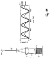
- Fig. 11 shows in the right area a diagram in which the intensity I R of the reflected light 4 in units of ⁇ Watt versus a path change ⁇ x in units of nm.
- the displacement ⁇ x of the folding mirror 7 was brought about by a piezo stack P.
- Fig. 12 shows by way of example a position detection device 300 which uses the light 4, which is reflected by a Fabry-Perot interferometer 100, 200 according to the invention, for determining the object position x.
- the position detection device 300 shown here operates on the principle of quadrature detection, which in the European patent application EP 2 045 572 A1, which is hereby incorporated by reference into the content of the present application.
- the denominator can be ignored to a first approximation and the reflectance of the Fabry-Perot interferometer fulfills the following proportionality reflectance ⁇ G 2 sin 2 ⁇ .
- G 2 ⁇ ⁇ 1 which is equivalent to reflectance ⁇ G 2 ⁇ 1 - cos 2 ⁇ ⁇ / Second
- the finesse F of the Fabry-Perot interferometer may be less than 10.0, 5.0, 1.0 or 0.5. The higher the value of the finesse F, the more difficult is a signal evaluation based on the evaluation of the curve form, since the cosine form according to equation (7) is then no longer complied with.
- At least one of the mirrors 1, 2, 7 can have a low degree of reflection.
- the reflectance of a planar polished end of a light guide 5 both in the region of the core 5a and in the region of the jacket 5b is about 4% and thus has the desired low reflectivity.
- the reflectivity levels of the resonator mirrors 1, 2 and the folding mirror 7 can also be tuned differently to each other.
- a large finesse of the Fabry-Perot interferometer 200 may also be desired, for example if the evaluation of the intensity I R is not based on the cosine shape of the intensity profile. This can be the case, for example, if no high spatial resolution is required and for the evaluation of the reflected light, for example, only the periodicity of the interference pattern, but not the curve between periodicity reference points (eg maxima) of I R is used.
- the position detection device 300 comprises an interferometer head 209, a detector arrangement 202, an evaluation circuit 204 and a light source (laser) 201. Specific examples of these components are given below.
- One of the outputs of the 1 ⁇ M coupler 208 is fed to a 2 ⁇ 2 coupler 206.
- the one output of the 2 ⁇ 2 coupler 206 is coupled into the interferometer head 209 via a SMF (Single Mode Fiber) 207.
- the interferometer head 209 may be e.g. be realized by one of the previously described confocal Fabry-Perot interferometer heads 100, 200.
- the interference light of intensity I R returned by the interferometer head 209 via the SMF 207 is fed to a detector 210.
- the detector 210 generates a measurement signal, which is fed to the evaluation circuit 204 after an optional amplification in an amplifier 220.
- a fixed wavelength laser 201 may be used and a detector signal corresponding to the one shown in FIG Fig. 11 intensity profile I R shown corresponds to or comprises only the frequency to be evaluated directly.
- a detector signal corresponding to the one shown in FIG Fig. 11 intensity profile I R shown corresponds to or comprises only the frequency to be evaluated directly.
- a position detection device 300 which performs a very accurate position determination on the basis of a so-called quadrature detection method.
- a tunable laser 201 is used as light source, with this a periodic wavelength modulation of the measurement light caused and an evaluation of the intensity I R of the confocal Fabry-Perot interferometer 100, 200 reflected light according to the quadrature principle by means of demodulation as a function of the modulation frequency of the measurement light carried out.
- demodulation as a function of the modulation frequency of the measurement light carried out.
- a quadrature evaluation can be carried out, for example, by demodulating the two time-variant components S ⁇ and S 2 ⁇ with the frequency f or the frequency 2f.
- the pre-factors 2 (P + 1) x ⁇ k and (2 (P + 1) x ⁇ k / 2) 2 of the signals S and S Q are unknown since they depend on the object location x, ie the searched value.
- an approximate value x estim for the object position is determined. Subsequently, a higher accuracy can be obtained by evaluating the quadrature detection signals S ⁇ -2 (P + 1) x estim ⁇ k sin (2 (P + 1) k 0 x) and S Q ⁇ - (2 (P + 1) x estim ⁇ k / 2) 2 cos (2 (P + 1 ) k 0 x) can be achieved by increment counting and interpolation.
- N denotes the count value of the increments of ⁇ / [8 (P + 1)] obtained during a displacement x from a reference point (zero point) x 0 .
- the approximate value x estim can be determined, for example, by measuring the maximum values max (S Q ) and max (S) of the signals S Q and S according to the equation x estim ⁇ (2 / ⁇ k) (max (S Q ) / max (S )) respectively.
- Such an evaluation of the detector signal supplied by the detector 220 may be performed by means of the in Fig. 12 Evaluation circuit 204 shown as an example.
- This includes a first lock-in amplifier 212-1 and a second lock-in amplifier 212-2, a first analog-to-digital converter 213-1, a second analog-to-digital converter 213-2, a processor 214 with access to a lookup
- the evaluation circuit 204 comprises a laser driver 216, which via a signal output of an AC generator 210 is controlled.
- the tunable laser 201 may be a DFB (Distributed)
- the laser 201 may be isolated by using a Faraday isolator such as 35 db to prevent it from being damaged or becoming unstable by reflected light.
- the demodulations of the measuring signal output by the detector 220 with the angular frequency ⁇ and the angular frequency 2 ⁇ are performed in the lock-in amplifiers 212-1 and 212-2, respectively.
- the reference inputs of the two lock-in amplifiers 212-1, 212-2 are connected to a TTL reference output of the AC generator 210.
- the measurement signal output at the output of the detector 220 is fed to the signal inputs of the two lock-in amplifiers 212-1 and 212-2.
- the first lock-in amplifier 212-1 is set to the reference angular frequency ⁇ and the second lock-in amplifier 212-2 is set to twice the reference angular frequency 2 ⁇ .
- S Q - (2 (P + 1) x ⁇ k / 2) 2 cos (2 (P + 1) k 0 x).
- the factor .delta..sub.k by the expression .delta..sub.k be approximated -2 ⁇ / ( ⁇ 0) 2, where ⁇ indicating the known Wellendorfnhub the wavelength modulation.
- the two output signals of the lock-in amplifiers 212-1, 212-2 are converted into digital signals by the analog / digital converters 213-1, 213-2.
- a first read at the output of the analogue to digital converters 213-1, 213-2 gives the displacement x in increments of ⁇ / [8 (P + 1)].
- MSB Mobile Scal Bit
- the most significant bit MSB (Most Significant Bit) at the output of each analog / digital converter is a counting input of the up / down counter.
- counter 215 may be a 24-bit counter with two counter inputs.
- a second reading of the outputs of the analog / digital converters 213-1, 213-2 is performed by the processor 214. This second readout may span the entire wordwidth of the transducer outputs.
- the interpolation can be done, for example, using a lookup table memory (LUT).
- the quadrature detection method can not necessarily be performed on the basis of the signal components S ⁇ and S 2 ⁇ , but also, for example, on the basis of the DC component S DC and one of the signal components S ⁇ or S 2 ⁇ . Because the DC component S DC is also dependent on x. In this case, one of the lock-in amplifiers 212-1, 212-2 may be omitted.
- the quadrature detection method it is always based on an evaluation of at least two signal components.
- the position detection device Due to its large number of favorable properties (high resolution, large measuring range, compactness of the interferometer head (structural dimensions less than 1 cm, weight less than 1 g), simple installation, minimal or no optical adjustment effort, the position detection device can be highly resistant to vibration since no rigid connecting lines are required ) are used in many applications and installation environments. In particular, use in extreme environments (LT, UHV, B, KV, T %) is possible.
- the position detection device can be used for monitoring the positioning movement of a positioner with a positioning accuracy in the sub-millimeter range or in the sub-micron range or in the nanometer range and even sub-nanometer range.
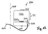
- a positioner 500 for translational movements is shown with a position detection device according to the invention in plan view.
- the positioner 500 has a first, fixed-position part 501 and a second part which is displaceable relative to the first part 501, which is referred to below as a carrier 504.
- a relative position adjustment device which can be realized, for example, by a translation axis 503 on which the carrier 504 can slide, and a piezoelectric element acting as an actuator 502.
- the direction of the translation movement is illustrated by a double arrow P1.
- the drive shown here is referred to as a so-called inertial engine or as a slip-stick drive.
- the increment of a positioning movement can not be defined exactly by controlling the drive. This means that a position determination of one arranged on the carrier 504 Positioning part in the positioner 500 can not be performed solely by monitoring the drive control (eg, a step count), but that the positioner 500 must be additionally equipped with a device that allows monitoring of the positioning position.
- a position detection device For this purpose, a position detection device according to one of the preceding embodiments is provided.
- an interferometer head 509 On the positionally fixed first part 501, an interferometer head 509 is mounted, which can be designed according to one of the preceding embodiments.
- the illuminating light emerging from the interferometer head 509 is incident on a mirror 511 mounted on the displaceable support 504, which is oriented perpendicular to the right of movement (double arrow P1) and reflects the light back to the interferometer head 503.
- the mirror 511 can be, for example, the folding mirror 7 or, in the case of in Fig. 4 also be the second resonator mirror 2 shown Fabry-Perot interferometer 100.
- the interferometer head 503 is connected via an optical fiber 507 to a detector arrangement (not shown), which may be designed according to one of the preceding embodiments and is in communication with the other components previously described (laser, evaluation circuit).
- UHV ultra high vacuum
- an optical resolution of about 1 nm or even less can be achieved.
- the step size is variable depending on the voltage for driving the piezoelectric element 502 and depending on the temperature between about 5 nm and 1 micron. Due to the high resolution of the optical position monitoring, therefore, a positioning accuracy in the range of the mechanical limits of the drive (about 5 nm) can be achieved. Particularly advantageous for many applications is the long maximum movement path, which can usually be several millimeters to one or more centimeters.
Abstract
Description
Die Erfindung betrifft eine Vorrichtung und ein Verfahren zur Positionserfassung sowie eine Anordnung, die einen Positionierer und eine Vorrichtung zur Positionserfassung aufweist.The invention relates to a device and a method for position detection and an arrangement comprising a positioner and a device for position detection.
In vielen Anwendungsbereichen ist es erforderlich, die Position eines Objektes oder einen von diesem zurückgelegten Weg zu erfassen. Beispielsweise müssen in der Förder- und Automatisierungstechnik Positionen von Objekten überwacht und ausgewertet werden. Ein spezielles Einsatzgebiet, bei welchem die Genauigkeit der Positionserfassung von besonderer Bedeutung ist, ist die Positioniertechnik, bei welcher ein Objekt gezielt und definiert verfahren wird. Derartige Positionierer kommen beispielsweise in der Forschung und Industrie zum Einsatz. Neben einer möglichst hohen Genauigkeit und einem gro-βen Messbereich spielen Eigenschaften wie Erschütterungs-Unempfindlichkeit, Robustheit und Kompaktheit des Aufbaus im praktischen Gebrauch eine wesentliche Rolle.In many applications it is necessary to detect the position of an object or a path traveled by it. For example, in the conveying and automation technology, positions of objects must be monitored and evaluated. A special field of application, in which the accuracy of the position detection is of particular importance, is the positioning technique, in which an object is moved selectively and defined. Such positioners are used, for example, in research and industry. In addition to the highest possible accuracy and a large measuring range, features such as vibration insensitivity, robustness and compactness of the structure play an essential role in practical use.
Aus der Schrift
Die Druckschrift
Die Druckschrift
Eine der Erfindung zugrunde liegende Aufgabe kann daher darin gesehen werden, eine Vorrichtung und ein Verfahren zur Positionserfassung zu schaffen, die bzw. das kostengünstig ist und in vielfältigsten Anwendungen zum Einsatz kommen kann. Insbesondere soll die Vorrichtung in einen Positionierer integrierbar sein und es erlauben, den von dem Positionierer erzeugten Positionierweg zu überwachen.An object of the invention is therefore to be seen to provide a device and a method for position detection, which is cost-effective and can be used in a variety of applications. In particular, the device should be able to be integrated into a positioner and allow the positioning path generated by the positioner to be monitored.
Die der Erfindung zugrunde liegende Aufgabenstellung wird durch die Merkmale der unabhängigen Ansprüche gelöst. Ausführungsformen und Weiterbildungen der Erfindung sind Gegenstand der abhängigen Ansprüche.The object of the invention is based solved by the features of the independent claims. Embodiments and developments of the invention are the subject of the dependent claims.
Gemäß Anspruch 1 weist die Vorrichtung zur Positionserfassung ein konfokales Fabry-Perot Interferometer auf. Die Konfokalität des eingesetzten Fabry-Perot Interferometers bewirkt, dass der im Resonator des Fabry-Perot Interferometers umlaufende Lichtstrahl unabhängig von Justagefehlern der im Strahlengang angeordneten Spiegel auf einen bekannten Punkt, der typischerweise der Eintrittpunkts eines in das Fabry-Perot Interferometer (Resonator) eingespeisten Lichtbündels ist, fokussiert wird. Dadurch kann ein einfacher und kostengünstiger Aufbau der Vorrichtung erreicht werden und es fällt ein geringer Justageaufwand beim Einbau der Vorrichtung in ihre Einbauumgebung, z.B. einen Positionierer, an. Darüber hinaus kann die erfindungsgemäße Vorrichtung in Einbauumgebungen mit ungünstigen Voraussetzungen (Vibrationen, geringer Einbauplatz) zum Einsatz kommen, wodurch eine Vielzahl von Anwendungen für die erfindungsgemäße Vorrichtung überhaupt erst ermöglicht werden.According to
Ebenfalls gemäß Anspruch 1 umfasst das konfokale Fabry-Perot Interferometer einen ersten und einen zweiten Resonatorspiegel und einen im Strahlengang zwischen dem ersten und dem zweiten Resonatorspiegel angeordneten Faltungsspiegel. Der Faltungsspiegel ist mit dem Objekt, dessen Position zu bestimmen ist, gekoppelt und ermöglicht eine Autofokussierung, die unabhängig von der Länge des Strahlengangs im Fabry-Perot Interferometer ist. Dadurch kann auf einfache Weise ein extrem großer Messbereich von z.B. 10 cm oder mehr erreicht werden.Likewise according to
Vorzugsweise umfasst das konfokale Fabry-Perot Interferometer einen im Strahlengang zwischen dem ersten und dem zweiten Resonatorspiegel angeordneten Kollimator. Der Kollimator dient der Bündelung bzw. Fokussierung des Strahlengangs im Fabry-Perot Interferometer und bewirkt in Verbindung mit dem Faltungsspiegel eine Autofokussierung, die unabhängig von der Länge des Strahlengangs im Fabry-Perot Interferometer ist. Ein oder mehrere Kollimatoren können auch in einem konfokalen Fabry-Perot Interferometer ohne Faltungsspiegel vorgesehen sein.Preferably, the confocal Fabry-Perot interferometer comprises a collimator arranged in the beam path between the first and second resonator mirrors. The collimator serves to focus or focus the beam path in the Fabry-Perot interferometer and, in conjunction with the folding mirror, effects autofocusing, which is independent of the length of the beam path in the Fabry-Perot interferometer. One or more collimators may also be provided in a confused Fabry-Perot interferometer without a folding mirror.
Vorzugsweise sind der erste und der zweite Resonatorspiegel relativ zueinander lagefest angeordnet. Dadurch kann ein kompaktes und robustes Fabry-Perot Interferometer realisiert werden.Preferably, the first and the second resonator mirrors are arranged fixed relative to one another in a positionally fixed manner. As a result, a compact and robust Fabry-Perot interferometer can be realized.
Zweckmäßigerweise ist die Finesse des Fabry-Perot Interferometers kleiner als 1,0, insbesondere kleiner als 0,5. In diesem Fall verhält sich der Interferenzkontrast des vom Fabry-Perot Interferometer erzeugten Interferenzmusters näherungsweise gemäß einer Kosinusfunktion in Abhängigkeit von der Objektposition. Dadurch wird die Auswertung eines durch Detektion des Interferenzmusters gewonnenen Messsignals in einer Auswerteschaltung wesentlich erleichtert und insbesondere die Auswertegenauigkeit erhöht.Conveniently, the finesse of the Fabry-Perot interferometer is less than 1.0, in particular less than 0.5. In this case, the interference contrast of the interference pattern generated by the Fabry-Perot interferometer behaves approximately according to a cosine function depending on the object position. As a result, the evaluation of a measurement signal obtained by detection of the interference pattern in an evaluation circuit is substantially facilitated and, in particular, the evaluation accuracy is increased.
Vorzugsweise sind der Reflexionsgrad des ersten Resonatorspiegels und der Reflexionsgrad des zweiten Resonatorspiegels in etwa gleich groß. Dadurch wird ein hoher Kontrast des Interferenzmusters und damit eine hohe Genauigkeit der Positionsbestimmung ermöglicht.Preferably, the reflectance of the first resonator mirror and the reflectance of the second resonator mirror are approximately equal. This allows a high contrast of the interference pattern and thus a high accuracy of the position determination.
Vorzugsweise ist der zweite Resonatorspiegel durch eine Endfläche eines seitlich neben dem ersten Resonatorspiegels angeordneten optischen Teils realisiert. Beispielsweise kann es sich bei dem ersten Resonatorspiegel um die Austrittsfläche eines Kerns eines Lichtleiters und bei dem zweiten Resonatorspiegel um den den Kern seitlich umgebenden Mantel des Lichtleiters handeln. Ermöglicht wird dadurch eine konstruktiv kompakte, stabile und kostengünstige Realisierung der beiden Resonatorspiegel, die - im Falle eines Lichtleiters - in denkbar einfacher Weise allein aus der polierten Endfläche des Lichtleiters (Mantelfläche und Kernfläche) erzeugt werden können.The second resonator mirror is preferably realized by an end face of an optical part arranged laterally next to the first resonator mirror. By way of example, the first resonator mirror may be the exit surface of a core of a light guide, and the second resonator mirror may be the jacket of the light guide laterally surrounding the core. This makes possible a structurally compact, stable and cost-effective realization of the two resonator mirrors, which - in the case of a light guide - can be generated in a very simple way from the polished end face of the light guide (lateral surface and core surface) alone.
Durch eine geeignete Dimensionierung des zweiten Resonatorspiegels und gegebenenfalls des Kollimators kann erreicht werden, dass die erfindungsgemäße Vorrichtung eine Wegmessung bzw. Positionsbestimmung über einen Messbereich von mehr als 10-4 m, insbesondere mehr als 10-3 m und ohne Weiteres auch mehr als 10-2 m durchführen kann. Die Auflösung kann dabei über den gesamten Messweg im Sub-Nanometerbereich liegen.By suitable dimensioning of the second resonator mirror and, if appropriate, of the collimator, it can be achieved that the device according to the invention measures a distance measurement or position determination over a measuring range of more than 10 -4 m, in particular more than 10 -3 m and, without further measures, more than 10 . 2 m can perform. The resolution can be over the entire measuring path in the sub-nanometer range.
Ein Verfahren zur Positionserfassung ist durch Anspruch 14 definiert. Das erfindungsgemäße Verfahren kann in der bereits beschriebenen Weise durch ein konstruktiv einfach aufgebautes Fabry-Perot Interferometer ausgeführt werden und erfordert einen vergleichsweise geringen Montage- und Justageaufwand.A method for position detection is defined by claim 14. The inventive method can be carried out in the manner already described by a structurally simple design Fabry-Perot interferometer and requires a relatively low installation and adjustment costs.
Die Erfindung wird nachfolgend in beispielhafter Weise anhand der Figuren näher erläutert; in diesen zeigen:
- Fig. 1
- eine schematische Prinzipdarstellung eines Fabry-Perot Interferometers zur Positionsbestimmung eines Objektes sowie ein Schaubild, in welchem die Intensität des vom Interferometer reflektierten Lichtes gegenüber der Objektposition dargestellt ist;
- Fig. 2
- eine schematische Darstellung eines Fabry-Perot Interferometers ohne Konfokaloptik;
- Fig. 3
- ein Schaubild, in welchem der von dem Fabry-Perot Interferometer erzeugte Interferenzmusterkontrast gegenüber einem Verkippungswinkel eines Resonatorspiegels gegenüber der optischen Achse des Interferometers dargestellt ist;
- Fig. 4
- eine schematische Darstellung eines konfokalen Fabry-Perot Interferometers;
- Fig. 5
- eine schematische Darstellung eines Ausführungsbeispiels eines konfokalen Fabry-Perot Interferometers mit einem Faltungsspiegel im Strahlengang des Interferometer-Resonators;
- Fig. 6
- ein Schaubild, in welchem der von dem in
Fig. 5 gezeigten konfokalen Fabry-Perot Interferometer erzeugte Interferenzmusterkontrast gegenüber einem Verkippungswinkel des Faltungsspiegels gegenüber der optischen Achse des Interferometers dargestellt ist; - Fig. 7
- eine schematische Darstellung des Strahlengangs des in
Fig. 5 gezeigten konfokalen Fabry-Perot Interferometers bei ausreichend verkipptem Faltungsspiegel; - Fig. 8
- eine schematische Darstellung des Strahlengangs des in
Fig. 5 gezeigten konfokalen Fabry-Perot Interferometers bei zu wenig verkipptem Faltungsspiegel; - Fig. 9
- eine schematische Darstellung einer Ausführungsvariante des konfokalen Fabry-Perot Interferometers nach
Fig. 7 ; - Fig. 10
- eine schematische Darstellung einer weiteren Ausführungsvariante des konfokalen Fabry-Perot Interferometers nach
Fig. 7 ; - Fig. 11
- eine schematische Darstellung einer Messanordnung sowie ein Schaubild, in welchem Messkurven der Intensität des von dem konfokalen Fabry-Perot Interferometer reflektierten Lichtes gegenüber der Objektposition für drei verschiedene Weglängen aufgetragen sind;
- Fig. 12
- eine schematische Darstellung einer Auswerteschaltung gemäß einem Ausführungsbeispiel der Erfindung; und
- Fig. 13
- eine schematische Darstellung eines Ausführungsbeispiels eines Positionierers für eine Translationsbewegung.
- Fig. 1
- a schematic diagram of a Fabry-Perot interferometer for determining the position of a Object and a graph showing the intensity of the reflected light from the interferometer with respect to the object position;
- Fig. 2
- a schematic representation of a Fabry-Perot interferometer without confocal optics;
- Fig. 3
- a graph in which the interference pattern contrast generated by the Fabry-Perot interferometer against a tilt angle of a resonator mirror relative to the optical axis of the interferometer is shown;
- Fig. 4
- a schematic representation of a confocal Fabry-Perot interferometer;
- Fig. 5
- a schematic representation of an embodiment of a confocal Fabry-Perot interferometer with a folding mirror in the beam path of the interferometer resonator;
- Fig. 6
- a diagram in which the of the in
Fig. 5 shown confocal Fabry-Perot interferometer generated interference pattern contrast to a tilt angle of the folding mirror with respect to the optical axis of the interferometer is shown; - Fig. 7
- a schematic representation of the beam path of in
Fig. 5 shown confocal Fabry-Perot interferometer with sufficiently tilted folding mirror; - Fig. 8
- a schematic representation of the beam path of in
Fig. 5 shown confocal Fabry-Perot interferometer with too little tilted folding mirror; - Fig. 9
- a schematic representation of an embodiment of the confocal Fabry-Perot interferometer according to
Fig. 7 ; - Fig. 10
- a schematic representation of another embodiment of the confocal Fabry-Perot interferometer according to
Fig. 7 ; - Fig. 11
- a schematic representation of a measuring arrangement and a graph in which measured curves of the intensity of the light reflected by the confocal Fabry-Perot interferometer light with respect to the object position for three different path lengths are plotted;
- Fig. 12
- a schematic representation of an evaluation circuit according to an embodiment of the invention; and
- Fig. 13
- a schematic representation of an embodiment of a positioner for a translational movement.
Durch Messung der Intensität des reflektierten Lichts 4 lässt sich der Spiegelabstand bzw. eine Änderung des Spiegelabstands ermitteln. Im unteren Teil der
Bei der in
Das Fabry-Perot Interferometer 20 funktioniert nur dann, wenn das von dem zweiten Resonatorspiegel 2 zurückgeworfene Licht nach der Fokussierung durch den Kollimator 6 wieder in den Kern 5a des Lichtleiters 5 eingekoppelt wird. Voraussetzung hierfür ist, dass der zweite Resonatorspiegel 2 mit hoher Genauigkeit senkrecht zur optischen Achse des Fabry-Perot Interferometers 20 ausgerichtet ist und diese Ausrichtung auch bei einer Bewegung des zweiten Resonatorspiegels 2 erhalten bleibt. Diese Bedingung ist konstruktiv bei einer Objektbewegung nur schwer zu erfüllen und macht in jedem Fall einen hohen Justageaufwand erforderlich. Dies lässt sich anhand einer einfachen Beispielrechnung erkennen: Der Durchmesser des Kerns 5a an der Austrittsfläche (d.h. der Durchmesser des ersten Resonatorspiegels 1) wird mit MFD (Mode Field Diameter) bezeichnet. Die Verkippung α des zweiten Resonatorspiegels 2 gegenüber seiner Idealposition muss die Bedingung α MFD/(4f) erfüllen, damit das von dem zweiten Resonatorspiegel 2 reflektierte Licht in den Kern 5a zurückgeführt wird und somit Interferenzmuster in dem reflektierten Licht 4 auftreten können. Bei MFD = 10 µm und f = 10 mm ergibt sich α 0,25 mRAD. Derselbe Wert würde sich beispielsweise bei MFD = 5 µm und f = 5 mm ergeben. Zur Erfüllung dieser Bedingung muss der zweite Resonatorspiegel 2 auf einer teuren Präzisionshalterung angebracht werden und eine perfekt verkippungsfreie Translationsbewegung des zweiten Resonatorspiegels 2 sichergestellt werden. Dies ist in der Praxis nicht oder nur mit hohem Aufwand zu erreichen.The Fabry-
Eine weitere Kenngröße eines Fabry-Perot Interferometers ist der Kontrast des im reflektierten Lichtes 4 vorhandenen Interferenzmusters. Dieser soll möglichst groß sein und beträgt optimalerweise 100%. Der Kontrast wird durch die Gleichung 
ausgedrückt. Dabei sind Rmin und RmaX durch die Ausdrücke 
und 
gegeben, wobei R1 den Reflexionsgrad des ersten Resonatorspiegels und R2 den Reflexionsgrad des zweiten Resonatorspiegels bezeichnen. Aus den Gleichungen ergibt sich, dass ein maximaler Kontrast für R1 = R2 erzielt wird, da in diesem Fall Rmin = 0 gilt. Dies bedeutet, dass bei dem in
expressed. Where R min and R max are by the terms
and
where R 1 is the reflectance of the first resonator mirror and R 2 is the reflectance of the second resonator mirror. It follows from the equations that a maximum contrast is achieved for R 1 = R 2 , since in this case R min = 0. This means that in the in
Erfindungsgemäß wird ein konfokales Fabry-Perot Interferometer eingesetzt, um das anhand
Das Fabry-Perot Interferometer 100 weist einen relativ kleinen Messbereich Δxmax auf, da dieser durch die Tiefenschärfe des Fokus auf dem zweiten Resonatorspiegel 2 begrenzt wird. In der Praxis ist der Messbereich z.B. auf etwa 40 µm begrenzt. Größere Verschiebungswege sind daher mit dem in
Die Faltung des Strahlengangs 3, 3' der in
Ein typischer, beispielhafter Wert für den Durchmesser D eines Lichtleiters ist D = 125 µm. Die Bedingung für den maximal zulässigen Verkippungswinkel α lautet α < D/(4f). Für f = 10 mm ergibt sich z.B. α < 3,125 mRAD.A typical, exemplary value for the diameter D of a light guide is D = 125 μm. The condition for the maximum allowable tilt angle α is α <D / (4f). For f = 10 mm, e.g. α <3.125 mRAD.
Es ist leicht zu erkennen, dass die erforderliche Justagegenauigkeit des Faltungsspiegels 7 im konfokalen Fabry-Perot Interferometer 200 um den Faktor D/MFD gegenüber der erforderlichen Justagegenauigkeit des zweiten Resonatorspiegels 2 in dem (nicht-konfokalen) Fabry-Perot Interferometer 20 relaxiert ist. Durch eine einfache Dimensionierung des Faserendes des Lichtleiters 5 (bzw. eines dort angebrachten Spiegels) lässt sich das Justageproblem idealerweise beliebig verkleinern.It can easily be seen that the required adjustment accuracy of the
Wie bereits erläutert, sollte für die Erzielung eines hohen Kontrasts im reflektierten Licht 4 die Bedingung R1 ≈ R2 gelten. Bei der in
Mit anderen Worten: Das in
Die
Es sind viele unterschiedliche Realisierungsmöglichkeiten für das in den
Die
In den bisherigen Ausführungsbeispielen wurden beispielsweise ebene Spiegel 1, 2, 7 betrachtet. Gemäß
Eine weitere, nicht dargestellte Ausführungsvariante des konfokalen Fabry-Perot Interferometers 200 kennzeichnet sich dadurch, dass der erste und/oder der zweite Resonatorspiegel 1, 2 nicht integral mit dem Lichtleiter 5 sind, sondern als ein oder mehrere separate optische Elemente realisiert sind. Beispielsweise können der erste und der zweite Resonatorspiegel 1, 2 durch eine oder mehrere teildurchlässige Spiegelscheiben realisiert sein, welche im Strahlengang vor dem Kollimator 6 angeordnet ist bzw. sind und von dem aus dem Lichtleiter 5 austretenden Messlicht durchlaufen wird bzw. werden. Eine radial innere und eine radial äußere Zone dieser Spiegelscheibe (oder zwei getrennte entsprechende Spiegelelemente) können den ersten bzw. den zweiten Resonatorspiegel 1, 2 bilden und beispielsweise unterschiedlich stark verspiegelt sein (insbesondere dann, wenn der Reflexionsgrad Rc des Faltungsspiegels kleiner als 100% ist, kann der Reflexionsgrad des zweiten Resonatorspiegels 2 höher als der des ersten sein). Ferner ist auch möglich, dass der Interferometer-Resonator durch geeignete Maßnahmen nicht nur zweifach (hin und zurück), sondern 4-fach, 6-fach usw. durchlaufen wird, wobei jeweils eine Messgenauigkeitserhöhung um den Faktor der Lichtwegverlängerung im Resonator auftritt.A further variant of the confocal Fabry-
Die Intensität des reflektierten Lichtes IR ist proportional zu dem Reflexionsgrad des Fabry-Perot Interferometers, der unter der (optionalen) Annahme eines Reflexionsgrades des Faltungsspiegels 7 von Rc = 1,0 (100%) allgemein durch den Ausdruck 
![]()
![]()
Die Finesse F ist durch F = (ng/2)1/2 bestimmt.The finesse F is determined by F = (ng / 2) 1/2 .
Für den Spezialfall R1 = R2 = R ergibt sich 
Sofern g2 <<1 gilt, kann der Nenner in erster Näherung ignoriert werden und die Reflexionsgrad des Fabry-Perot Interferometers erfüllt die folgende Proportionalität ![]()
was äquivalent ist zu ![]()
![]()
which is equivalent to ![]()
Die Intensität IR des reflektierten Lichts 4 ist daher für R1 = R2 = R und kleine Werte von R ein Signal mit einem variierenden Anteil cos(2(P+1)kx) mit k = 2π/λ und P = Faltungsgrad (P=0 <-> keine Faltung, P=1 <-> 1 Faltungspiegel, u.s.w.), siehe z.B.
Die Finesse F des Fabry-Perot Interferometers kann beispielsweise kleiner als 10,0, 5,0, 1,0 oder 0,5 sein. Je höher der Wert der Finesse F, desto schwieriger wird eine auf der Auswertung der Kurvenform beruhende Signalauswertung, da die Kosinusform gemäß Gleichung (7) dann nicht mehr eingehalten wird.For example, the finesse F of the Fabry-Perot interferometer may be less than 10.0, 5.0, 1.0 or 0.5. The higher the value of the finesse F, the more difficult is a signal evaluation based on the evaluation of the curve form, since the cosine form according to equation (7) is then no longer complied with.
Um eine geringe Finesse F zu erreichen, kann wenigstens einer der Spiegel 1, 2, 7 einen geringen Reflexionsgrad aufweisen. Typischerweise liegt der Reflexionsgrad eines ebenen polierten Endes eines Lichtleiters 5 sowohl im Bereich des Kern 5a als auch im Bereich des Mantels 5b bei etwa 4% und weist somit die gewünschte niedrige Reflexivität auf.In order to achieve a low finesse F, at least one of the
Es wird darauf hingewiesen, dass die Reflexivitätsgrade der Resonatorspiegel 1, 2 und des Faltungsspiegels 7 auch anders aufeinander abgestimmt sein können. Ein hoher Kontrast des Interferenzmusters im reflektierten Licht, d.h. Rmin = 0, sollte dabei stets angestrebt werden, wobei jedoch bei Rc ≠ 100% und insbesondere bei kleinen Werten für Rc diese Bedingung bei (gegebenenfalls sehr) unterschiedlichen Werten von R1 und R2 erfüllt ist. Insofern kann beispielsweise vorgesehen sein, dass die Austrittsfläche des Kerns 5a (oder eines vom Lichtleiter 5 separierten ersten Resonatorspiegels 1) und die Stirnfläche des Mantels 5b (oder eines vom Lichtleiter 5 separierten zweiten Resonatorspiegels 2) unterschiedliche Reflexionsgrade aufweisen, d.h. unterschiedlich stark verspiegelt sind. Ferner kann statt einer kleinen Finesse F auch eine große Finesse des Fabry-Perot Interferometers 200 gewünscht sein, beispielsweise dann, wenn die Auswertung der Intensität IR nicht auf der Kosinusform des Intensitätsverlaufs beruht. Dies kann beispielsweise der Fall sein, wenn keine hohe Ortsauflösung benötigt wird und zur Auswertung des reflektierten Lichtes z.B. lediglich die Periodizität des Interferenzmusters, nicht jedoch der Kurvenverlauf zwischen Periodizitätsbezugspunkten (z.B. Maxima) von IR herangezogen wird.It should be noted that the reflectivity levels of the resonator mirrors 1, 2 and the
Die Positionserfassungseinrichtung 300 umfasst einen Interferometerkopf 209, eine Detektoranordnung 202, eine Auswerteschaltung 204 und eine Lichtquelle (Laser) 201. Im folgenden werden spezielle Beispiele für diese Komponenten angegeben.The
Die Detektoranordnung 202 kann beispielsweise eingangsseitig einen 1×M Koppler 208 aufweisen, welcher M unabhängige Laserausgänge bereitstellt. Wird beispielsweise eine Überwachung der Objektbewegung in drei Dimensionen durchgeführt, kann M = 3 gewählt werden. An den beiden freien Ausgängen des 1×3 Kopplers 208 können in diesem Fall zwei weitere interferometrische Positionserfassungsvorrichtungen angeschlossen werden.The detector arrangement 202 can, for example, have on the input side a 1 ×
Einer der Ausgänge des 1×M Kopplers 208 wird einem 2×2 Koppler 206 zugeleitet. Der eine Ausgang des 2×2 Kopplers 206 wird über eine SMF (Single Mode Fiber) 207 in den Interferometerkopf 209 eingekoppelt. Der Interferometerkopf 209 kann z.B. durch einen der zuvor beschriebenen konfokalen Fabry-Perot Interferometerköpfe 100, 200 realisiert sein.One of the outputs of the 1 ×
Das von dem Interferometerkopf 209 über die SMF 207 zurückgeleitete Interferenzlicht der Intensität IR wird einem Detektor 210 zugeleitet. Der Detektor 210 erzeugt ein Messsignal, das nach einer optionalen Verstärkung in einem Verstärker 220 der Auswerteschaltung 204 zugeleitet wird.The interference light of intensity I R returned by the
Für Anwendungsfälle, in denen keine hohen Genauigkeiten erforderlich sind, sind einfache Auswerteprozeduren möglich. Beispielsweise kann ein Laser 201 mit fester Wellenlänge eingesetzt werden und es kann ein Detektorsignal, das dem in
Im Folgenden wird beispielhaft anhand
Zum Verständnis der Quadratur-Detektionsmethode wird zunächst der mathematische Hintergrund kurz beschrieben. Das normierte Detektorsignal ist bei einem konfokalen Fabry-Perot Interferometer 100, 200 mit kleiner Finesse durch ![]()
gegeben, wobei k über k = 2π/λ mit der zeitlich variierenden Wellenlänge λ des durchstimmbaren Lasers 201 in Beziehung steht. Die Modulation des Messlichtes kann durch ![]()
![]()
angegeben werden kann. Der Term SDC ist eine zeitunabhängige Komponente und ergibt sich zu ![]()
![]()
given k with k = 2π / λ with the time-varying wavelength λ of the tunable laser 201 in relation. The modulation of the measuring light can by ![]()
![]()
can be specified. The term S DC is a time-independent component and results in ![]()
Der zweite Term Sω ist eine zeitabhängige Komponente, die eine periodische, zeitliche Oszillation mit der Modulationsfrequenz f gemäß ![]()
vollzieht, wobei ω= 2πf. Der dritte Term S2ω ist ebenfalls eine zeitlich veränderliche Komponente, die eine periodische Oszillation mit der doppelten Modulationsfrequenz, d.h. 2f, darstellt ![]()
![]()
takes place, where ω = 2πf. The third term S 2ω is also a time-varying component representing a periodic oscillation at twice the modulation frequency, ie 2f ![]()
Eine Quadratur-Auswertung kann beispielsweise dadurch erfolgen, dass die beiden zeitveränderlichen Komponenten Sω und S2ω mit der Frequenz f bzw. der Frequenz 2f demoduliert werden. Die durch die Demodulation gewonnenen demodulierten Signale sind proportional zu ![]()
und ![]()
![]()
and ![]()
Die Vorfaktoren 2(P+1)xδk und (2(P+1)xδk/2)2der Signale S und SQ sind unbekannt, da sie von dem Objektort x, d.h. dem gesuchten Wert, abhängen.The pre-factors 2 (P + 1) xδk and (2 (P + 1) xδk / 2) 2 of the signals S and S Q are unknown since they depend on the object location x, ie the searched value.
Zunächst wird daher ein ungefährer Wert xestim für die Objektposition ermittelt. Anschließend kann eine höhere Genauigkeit durch eine Auswertung der Quadratur-Detektionssignale S ≈ -2(P+1)xestimδk sin(2(P+1)k0x) und SQ ≈ -(2(P+1) xestimδk/2)2cos (2(P+1)k0x) durch eine Inkrementzählung und eine Interpolation erzielt werden. Unter Verwendung dieser Quadratur-Detektion-demodulierten Terme ergibt sich die Position x mit einer hohen Genauigkeit, die im Sub-Nanometerbereich liegen kann, zu 
Dabei bezeichnet N den Zählwert der Inkremente von λ/[8(P+1)], der während einer Verschiebung x von einem Bezugspunkt (Nullpunkt) x0 erhalten wurde.N denotes the count value of the increments of λ / [8 (P + 1)] obtained during a displacement x from a reference point (zero point) x 0 .
Die Ermittlung des ungefähren Werts xestim kann beispielsweise Durch Messung der Maximalwerte max(SQ) und max(S) der Signale SQ und S nach der Gleichung xestim ≈ (2/δk) (max (SQ) /max (S)) erfolgen.The approximate value x estim can be determined, for example, by measuring the maximum values max (S Q ) and max (S) of the signals S Q and S according to the equation x estim ≈ (2 / δk) (max (S Q ) / max (S )) respectively.
Eine solche Auswertung des von dem Detektor 220 gelieferten Detektorsignals kann mittels der in
Die Demodulationen des von dem Detektor 220 ausgegebenen Messsignals mit der Winkelfrequenz ω und der Winkelfrequenz 2ω werden in den Lock-in Verstärkern 212-1 bzw. 212-2 durchgeführt. Zu diesem Zweck sind die Referenzeingänge der beiden Lock-in Verstärker 212-1, 212-2 mit einem TTL Referenzausgang des Wechselspannungsgenerators 210 verbunden. Das am Ausgang des Detektors 220 ausgegebene Messsignal wird in die Signaleingänge der beiden Lock-in Verstärker 212-1 und 212-2 eingespeist. Der erste Lock-in Verstärker 212-1 wird auf die Referenzwinkelfrequenz ω und der zweite Lock-in Verstärker 212-2 wird auf die doppelte Referenzwinkelfrequenz 2ωeingestellt. Der synchron mit ω betriebene erste Lock-in Verstärker 212-1 erzeugt ein demoduliertes Signal S = -xδk sin (2(P+1)k0x) und der synchron zu der Winkelfrequenz 2ω arbeitende zweite Lock-in Verstärker 212-2 liefert ein Quadratur-Detektionssignal SQ = -(2(P+1)xδk/2)2 cos(2(P+1)k0x). Unter der optionalen Bedingung δλ << λ0 kann der Faktor δk durch den Ausdruck δk = -2πδλ/(λ0)2 approximiert werden, wobei δλ den bekannten Wellenlängenhub der Wellenlängenmodulation angibt. Die beiden Ausgangssignale der Lock-in Verstärker 212-1, 212-2 werden von den Analog/Digital-Wandlern 213-1, 213-2 in digitale Signale gewandelt. Eine erste Auslesung am Ausgang der Analog/Digital-Wandler 213-1, 213-2 ergibt den Verschiebeweg x in Inkrementen von λ/[8(P+1)]. Zu diesem Zweck wird jeweils das höchstwertigste Bit MSB (Most Significant Bit) am Ausgang jedes Analog/Digital-Wandlers einem Zähleingang des Aufwärts-/Abwärts-Zählers zugeleitet. Die Position x wird durch das nächstliegendste Inkrement XN nach 
ermittelt. Beispielsweise kann als Zähler 215 ein 24-Bit-Zähler mit zwei Zähleingängen verwendet werden.The demodulations of the measuring signal output by the
determined. For example, counter 215 may be a 24-bit counter with two counter inputs.
Für die Berechnung von δx innerhalb eines Inkrements λ/8 wird eine zweite Auslesung der Ausgänge der Analog/Digital-Wandler 213-1, 213-2 von dem Prozessor 214 vorgenommen. Diese zweite Auslesung kann sich über die gesamte Wortbreite der Wandlerausgänge erstrecken. Ein in dem Prozessor 214 enthaltener Interpolator bearbeitet die beiden demodulierten Signale S und SQ und bestimmt δx gemäß der folgenden Beziehung: 
Der Wert x wird dann durch die Summe des Ausgangs des Aufwärts-/Abwärts-Zählers 215 und des Interpolators im Prozessor 214 gemäß ![]()
ermittelt. Die Interpolation kann beispielsweise anhand eines Nachschlage-Tabellenspeichers (LUT) erfolgen.The value x is then determined by the sum of the output of the up / down ![]()
determined. The interpolation can be done, for example, using a lookup table memory (LUT).
Es wird darauf hingewiesen dass die Quadratur-Detektionsmethode nicht notwendigerweise auf der Basis der Signalkomponenten Sω und S2ω, sondern beispielsweise auch anhand der Gleichkomponente SDC und einer der Signalkomponenten Sω oder S2ω durchführt werden kann. Denn die Gleichkomponente SDC ist ebenfalls von x abhängig. In diesem Fall kann einer der Lock-in Verstärker 212-1, 212-2 entfallen. Die Quadratur-Detektionsmethode beruht jedoch immer auf einer Auswertung von zumindest zwei Signalkomponenten.It should be noted that the quadrature detection method can not necessarily be performed on the basis of the signal components Sω and S 2ω , but also, for example, on the basis of the DC component S DC and one of the signal components Sω or S 2ω . Because the DC component S DC is also dependent on x. In this case, one of the lock-in amplifiers 212-1, 212-2 may be omitted. The quadrature detection method However, it is always based on an evaluation of at least two signal components.
Die Positionserfassungseinrichtung kann aufgrund ihrer Vielzahl von günstigen Eigenschaften (hohe Auflösung, großer Messbereich, Kompaktheit des Interferometerkopfes (bauliche Abmessungen kleiner als 1 cm, Gewicht kleiner als 1 g), einfacher Einbau, minimaler oder kein optischer Justageaufwand, hohe Vibrationsfestigkeit da keine steifen Verbindungsleitungen erforderlich) in vielen Anwendungen und Einbauumgebungen zum Einsatz kommen. Insbesondere ist ein Einsatz in extremen Umgebungen (LT, UHV, B, KV, T ...) möglich.Due to its large number of favorable properties (high resolution, large measuring range, compactness of the interferometer head (structural dimensions less than 1 cm, weight less than 1 g), simple installation, minimal or no optical adjustment effort, the position detection device can be highly resistant to vibration since no rigid connecting lines are required ) are used in many applications and installation environments. In particular, use in extreme environments (LT, UHV, B, KV, T ...) is possible.
Beispielsweise kann die Positionserfassungseinrichtung zur Überwachung der Positionierbewegung eines Positionierers mit einer Positioniergenauigkeit im Sub-Millimeter-Bereich oder im Sub-Mikrometer-Bereich oder im Nanometerbereich und sogar Sub-Nanometerbereich eingesetzt werden. In
Der hier dargestellte Antrieb wird als sogenannter Trägheitsmotor oder auch als Slip-Stick-Antrieb bezeichnet. Bei Slip-Stick-Antrieben, aber auch bei anderen Konstruktionstypen, ist die Schrittweite einer Positionierbewegung nicht exakt über die Ansteuerung des Antriebs definierbar. Dies bedeutet, dass eine Lagebestimmung eines auf dem Träger 504 angeordneten Positionierteils im Positionierer 500 nicht allein anhand einer Überwachung der Antriebssteuerung (z.B. einer Schrittzählung) durchgeführt werden kann, sondern dass der Positionierer 500 zusätzlich mit einer Vorrichtung ausgerüstet sein muss, welche eine Überwachung der Positionierlage ermöglicht.The drive shown here is referred to as a so-called inertial engine or as a slip-stick drive. For slip-stick drives, but also for other design types, the increment of a positioning movement can not be defined exactly by controlling the drive. This means that a position determination of one arranged on the
Zu diesem Zweck ist eine Positionserfassungseinrichtung gemäß einem der vorhergehenden Ausführungsbeispiele vorgesehen. An dem lagefesten ersten Teil 501 ist ein Interferometerkopf 509 gehaltert, der gemäß einem der vorhergehenden Ausführungsbeispiele ausgeführt sein kann. Das aus dem Interferometerkopf 509 austretende Beleuchtungslicht fällt auf einen an dem verschieblichen Träger 504 angebrachten Spiegel 511, welcher senkrecht zur Bewegungsrechtung (Doppelpfeil P1) orientiert ist und das Licht zum Interferometerkopf 503 zurück reflektiert. Der Spiegel 511 kann beispielsweise der Faltungsspiegel 7 oder, im Fall des in
Die strichpunktierte Linie 510 repräsentiert eine Systemgrenze, wie sie beispielsweise durch eine Wandung eines Kryostaten oder eines anderen Behältnisses realisiert sein kann. Es wird deutlich, dass lediglich der Interferometerkopf 508 (ohne Detektorelemente) innerhalb des abgeschlossenen Systems untergebracht sein muss und - wie in
Bei dem Translations-Positionierer 500 kann eine optische Auflösung von etwa 1 nm oder sogar darunter erreicht werden. Die Schrittgröße ist in Abhängigkeit von der Spannung zur Ansteuerung des Piezoelementes 502 und in Abhängigkeit von der Temperatur zwischen etwa 5 nm und 1 µm variierbar. Aufgrund der hohen Auflösung der optischen Positionsüberwachung kann also eine Positioniergenauigkeit im Bereich der mechanischen Grenzen des Antriebs (etwa 5 nm) erreicht werden. Besonders vorteilhaft für viele Anwendungen ist der lange maximale Bewegungsweg, der in der Regel mehrere Millimeter bis hin zu ein oder mehreren Zentimetern betragen kann.In the
Claims (14)
- Device for detecting position, having a confocal Fabry-Perot interferometer (100, 200) which comprises a first and a second resonator mirror (1, 2) and a folding mirror (7) arranged in the beam path between the first and the second resonator mirror (1, 2), in which the folding mirror (7) is designed to be mechanically coupled to an object whose position is to be determined, and in which the folding mirror (7) is orientated such that it directs the beam path in the Fabry-Perot interferometer (200) from the first (1) to the second (2) resonator mirror and from the second (2) to the first (1) resonator mirror.
- Device according to Claim 1, in which the confocal Fabry-Perot interferometer (100, 200) comprises a collimator (6, 6') arranged in the beam path between the first and the second resonator mirrors (1, 2).
- Device according to one of the preceding claims, in which the folding mirror (7) has a reflectivity greater than 0.9, in particular greater than 0.95.
- Device according to one of the preceding claims, in which the first and the second resonator mirrors (1, 2) are arranged radially offset from one another with reference to an optical axis of the Fabry-Perot interferometer (200).
- Device according to one of the preceding claims, in which the first and the second resonator mirrors (1, 2) are arranged fixedly with reference to one another.
- Device according to one of the preceding claims, in which the finesse of the Fabry-Perot interferometer (100, 200) is smaller than 1.0, in particular smaller than 0.5.
- Device according to one of the preceding claims, in which the reflectivity of the first resonator mirror (1) is smaller than 0.15, in particular smaller than 0.07, and the reflectivity of the second resonator mirror (2) is smaller than 0.15, in particular smaller than 0.07.
- Device according to one of the preceding claims, in which the reflectivity of the first resonator mirror (1) and the reflectivity of the second resonator mirror (2) are approximately equally large.
- Device according to one of the preceding claims, in which the first resonator mirror (1) comprises the exit surface of a core (5a) of a light guide (5).
- Device according to one of the preceding claims, in which the second resonator mirror (2) comprises an end face of an optical part arranged laterally next to the first resonator mirror, in particular the cladding (5b) of a light guide (5).
- Device according to one of the preceding claims, having a light source (201) for producing a measuring light fed to the Fabry-Perot interferometer (100, 200), a detector (210) for producing a measurement signal as a function of an interference pattern produced by means of the Fabry-Perot interferometer (100, 200), and an evaluation circuit (204) for evaluating the measurement signal.
- Device according to one of the preceding claims, in which the device is designed to carry out a position measurement over a measuring range of more than 10-4 m, in particular more than 10-3 m, furthermore in particular more than 10-2 m.
- Arrangement composed of a positioner and a device for detecting position, which comprises:the positioner (500) and a device for detecting position (100, 200, 300) in accordance with one of the preceding claims.
- Method for determining position, having the steps of:producing an interference pattern dependent on the position of an object by means of a confocal Fabry-Perot interferometer (100, 200) which comprises a first and a second resonator mirror (1, 2) and a folding mirror (7) arranged in the beam path between the first and the second resonator mirror (1, 2), the folding mirror (7) being mechanically coupled to an object whose position is to be determined, and the folding mirror (7) being orientated such that it directs the beam path in the Fabry-Perot interferometer (200) from the first (1) to the second (2) resonator mirror and from the second (2) to the first (1) resonator mirror;detecting the interference pattern; andevaluating a measurement signal obtained by the detection in order to determine the object position.
Priority Applications (3)
| Application Number | Priority Date | Filing Date | Title |
|---|---|---|---|
| EP10153054.1A EP2363685B1 (en) | 2010-02-09 | 2010-02-09 | Positioning device with confocal Fabry-Perot interferometer |
| US13/022,901 US8773666B2 (en) | 2010-02-09 | 2011-02-08 | Device and method for acquiring position with a confocal Fabry-Perot interferometer |
| JP2011026084A JP5306386B2 (en) | 2010-02-09 | 2011-02-09 | A device that acquires position using a Fabry-Perot interferometer |
Applications Claiming Priority (1)
| Application Number | Priority Date | Filing Date | Title |
|---|---|---|---|
| EP10153054.1A EP2363685B1 (en) | 2010-02-09 | 2010-02-09 | Positioning device with confocal Fabry-Perot interferometer |
Publications (2)
| Publication Number | Publication Date |
|---|---|
| EP2363685A1 EP2363685A1 (en) | 2011-09-07 |
| EP2363685B1 true EP2363685B1 (en) | 2013-11-20 |
Family
ID=42200873
Family Applications (1)
| Application Number | Title | Priority Date | Filing Date |
|---|---|---|---|
| EP10153054.1A Active EP2363685B1 (en) | 2010-02-09 | 2010-02-09 | Positioning device with confocal Fabry-Perot interferometer |
Country Status (3)
| Country | Link |
|---|---|
| US (1) | US8773666B2 (en) |
| EP (1) | EP2363685B1 (en) |
| JP (1) | JP5306386B2 (en) |
Cited By (1)
| Publication number | Priority date | Publication date | Assignee | Title |
|---|---|---|---|---|
| DE102018218488A1 (en) | 2018-10-29 | 2018-12-13 | Carl Zeiss Smt Gmbh | Measuring arrangement for the interferometric absolute measurement of the distance between two components in an optical system for microlithography |
Families Citing this family (10)
| Publication number | Priority date | Publication date | Assignee | Title |
|---|---|---|---|---|
| DE102011056002A1 (en) * | 2011-12-02 | 2013-06-06 | Grintech Gmbh | Optically correcting microprobe for white light interferometry |
| DE102012217700B4 (en) * | 2012-09-28 | 2015-03-12 | Carl Zeiss Smt Gmbh | Measuring device for measuring a beam position |
| EP2806246B1 (en) | 2013-05-24 | 2019-11-20 | Attocube Systems AG | Dual laser interferometer |
| CN104515621B (en) * | 2014-12-24 | 2017-09-08 | 天津大学 | Fibre optic temperature sensor based on closed microcavity Thermal effect and preparation method thereof |
| DE102016103109B4 (en) | 2016-02-23 | 2018-07-26 | Björn Habrich | MEASURING A CAVITY THROUGH INTERFERENCE SPECTROSCOPY |
| US10107614B1 (en) * | 2017-04-18 | 2018-10-23 | Quality Vision International, Inc. | Optical pen for interferometric measuring machine |
| JP7115675B2 (en) | 2018-02-27 | 2022-08-09 | 公立大学法人北九州市立大学 | Position detection device and shape detection device |
| DE102018208147A1 (en) * | 2018-05-24 | 2019-11-28 | Carl Zeiss Smt Gmbh | Measuring arrangement for frequenszbasierten position determination of a component |
| CN110726366A (en) * | 2019-10-28 | 2020-01-24 | 哈尔滨工业大学 | Nonlinear error correction method for optical fiber Fabry-Perot interferometer |
| EP3872444A1 (en) * | 2020-02-25 | 2021-09-01 | ASML Netherlands B.V. | Interferometer system and lithographic apparatus |
Family Cites Families (16)
| Publication number | Priority date | Publication date | Assignee | Title |
|---|---|---|---|---|
| WO1983003010A1 (en) * | 1982-02-24 | 1983-09-01 | Jackson, David, Alfred | Optical displacement sensing apparatus |
| JPH02276961A (en) * | 1989-04-19 | 1990-11-13 | Nippon Steel Corp | Laser ultrasonic flaw detector |
| DE4018998A1 (en) * | 1990-06-13 | 1992-01-02 | Dynisco Geraete Gmbh | FIBER OPTICAL PRESSURE SENSOR |
| JP3304696B2 (en) * | 1995-04-17 | 2002-07-22 | 株式会社先進材料利用ガスジェネレータ研究所 | Optical sensor |
| JP2923779B1 (en) * | 1998-06-18 | 1999-07-26 | 工業技術院長 | Optical interference device for ultrasonic detection |
| JP2001280914A (en) * | 2000-03-29 | 2001-10-10 | Tokyo Sokki Kenkyusho Co Ltd | Method of measuring optical interference |
| JP4113654B2 (en) | 2000-05-10 | 2008-07-09 | 株式会社東芝 | Laser ultrasonic inspection equipment |
| SE524828C2 (en) * | 2002-06-06 | 2004-10-12 | Alfa Exx Ab | Resonator |
| SE526267C2 (en) | 2003-12-05 | 2005-08-09 | Alfa Exx Ab | Optical measuring device |
| US7492463B2 (en) * | 2004-04-15 | 2009-02-17 | Davidson Instruments Inc. | Method and apparatus for continuous readout of Fabry-Perot fiber optic sensor |
| JP4439363B2 (en) | 2004-09-17 | 2010-03-24 | 新日本製鐵株式会社 | Online crystal grain size measuring apparatus and measuring method using laser ultrasonic wave |
| US20060274323A1 (en) * | 2005-03-16 | 2006-12-07 | Gibler William N | High intensity fabry-perot sensor |
| ATE549597T1 (en) | 2007-10-04 | 2012-03-15 | Attocube Systems Ag | DEVICE FOR POSITION DETECTION |
| US7898731B2 (en) * | 2007-11-20 | 2011-03-01 | The Regents Of The University Of California | Fiber optical parametric oscillator with high power and bandwidth |
| CN101562310B (en) * | 2009-05-04 | 2010-09-01 | 北京国科世纪激光技术有限公司 | Passive mode-locking picosecond laser |
| TWI431243B (en) * | 2009-06-19 | 2014-03-21 | Zygo Corp | An optical assembly for use in an interferometer, an interferometry system, and an interferometry method |
-
2010
- 2010-02-09 EP EP10153054.1A patent/EP2363685B1/en active Active
-
2011
- 2011-02-08 US US13/022,901 patent/US8773666B2/en active Active
- 2011-02-09 JP JP2011026084A patent/JP5306386B2/en active Active
Cited By (1)
| Publication number | Priority date | Publication date | Assignee | Title |
|---|---|---|---|---|
| DE102018218488A1 (en) | 2018-10-29 | 2018-12-13 | Carl Zeiss Smt Gmbh | Measuring arrangement for the interferometric absolute measurement of the distance between two components in an optical system for microlithography |
Also Published As
| Publication number | Publication date |
|---|---|
| EP2363685A1 (en) | 2011-09-07 |
| JP2011174922A (en) | 2011-09-08 |
| US8773666B2 (en) | 2014-07-08 |
| JP5306386B2 (en) | 2013-10-02 |
| US20110211199A1 (en) | 2011-09-01 |
Similar Documents
| Publication | Publication Date | Title |
|---|---|---|
| EP2363685B1 (en) | Positioning device with confocal Fabry-Perot interferometer | |
| EP0618439B1 (en) | Imaging optical device for examination of strongly scattering media | |
| DE19514852C2 (en) | Method and arrangement for acceleration and vibration measurement | |
| EP1430486B1 (en) | Method and device for analysing a sample by means of a raster scanning probe microscope | |
| EP2045572B1 (en) | Apparatus for determining a position | |
| DE2164397C3 (en) | Optoelectric tracking device | |
| DE3609507C2 (en) | Fiber optic interferometer | |
| EP0438675A2 (en) | Interferometric sensor to measure distance-variations of a small surface | |
| EP0876595A1 (en) | Low-coherence interferometric device | |
| EP0271646B1 (en) | Device for the contactless measurement of a distance from a surface, especially for the palpation of a contour of a surface of a worked article along a measuring path | |
| DE10033189C1 (en) | Low-coherence interferometry device has short coherence interferometer with scanning objective and beam splitter moved in synchronism during depth scanning of object | |
| DE102011004477A1 (en) | Scanning mirror device | |
| WO2010006764A2 (en) | Fibre-optic multiwavelength interferometer (mwli) for the absolute measurement of distances and topologies for surfaces at a large operating distance | |
| EP0604645B1 (en) | Fibre-optic sensor based on the fabry-perot principle | |
| EP3608625B1 (en) | Oct measuring system | |
| EP1546645B1 (en) | Interferometric measuring device | |
| EP1262734A1 (en) | Device to measure an object without contact, in particular to measure distance and/or vibration | |
| EP1258767A1 (en) | Microscope and method of using a microscope | |
| DE60211388T2 (en) | SENSOR WITH KANTILEVER AND OPTICAL RESONATOR | |
| DE102006060584B4 (en) | Method and device for measuring displacements and / or a geometry of microstructures | |
| DE3313861C2 (en) | Holder for a pair of plane mirrors and a ball in an interferometer length measuring device | |
| EP1174680A2 (en) | Device for varying the path length of an electromagnetic wave | |
| DE19713746C2 (en) | Sensor for simultaneous atomic force microscopy and optical near-field microscopy | |
| DE4233399C2 (en) | force microscope | |
| DE10039094C1 (en) | Apparatus for measurement of e.g. distances in biophysics comprises laser and prism from whose surface light is totally internally reflected, producing light field captured by optical wave guide which feeds it to photodetector |
Legal Events
| Date | Code | Title | Description |
|---|---|---|---|
| PUAI | Public reference made under article 153(3) epc to a published international application that has entered the european phase |
Free format text: ORIGINAL CODE: 0009012 |
|
| AK | Designated contracting states |
Kind code of ref document: A1 Designated state(s): AT BE BG CH CY CZ DE DK EE ES FI FR GB GR HR HU IE IS IT LI LT LU LV MC MK MT NL NO PL PT RO SE SI SK SM TR |
|
| AX | Request for extension of the european patent |
Extension state: AL BA RS |
|
| 17P | Request for examination filed |
Effective date: 20120307 |
|
| 17Q | First examination report despatched |
Effective date: 20120809 |
|
| GRAP | Despatch of communication of intention to grant a patent |
Free format text: ORIGINAL CODE: EPIDOSNIGR1 |
|
| RIN1 | Information on inventor provided before grant (corrected) |
Inventor name: BRAUN, PIERRE-FRANCOIS Inventor name: KARRAI, KHALED |
|
| GRAP | Despatch of communication of intention to grant a patent |
Free format text: ORIGINAL CODE: EPIDOSNIGR1 |
|
| INTG | Intention to grant announced |
Effective date: 20130620 |
|
| GRAS | Grant fee paid |
Free format text: ORIGINAL CODE: EPIDOSNIGR3 |
|
| GRAA | (expected) grant |
Free format text: ORIGINAL CODE: 0009210 |
|
| AK | Designated contracting states |
Kind code of ref document: B1 Designated state(s): AT BE BG CH CY CZ DE DK EE ES FI FR GB GR HR HU IE IS IT LI LT LU LV MC MK MT NL NO PL PT RO SE SI SK SM TR |
|
| REG | Reference to a national code |
Ref country code: GB Ref legal event code: FG4D Free format text: NOT ENGLISH |
|
| REG | Reference to a national code |
Ref country code: CH Ref legal event code: EP |
|
| REG | Reference to a national code |
Ref country code: AT Ref legal event code: REF Ref document number: 641894 Country of ref document: AT Kind code of ref document: T Effective date: 20131215 |
|
| REG | Reference to a national code |
Ref country code: IE Ref legal event code: FG4D Free format text: LANGUAGE OF EP DOCUMENT: GERMAN |
|
| REG | Reference to a national code |
Ref country code: DE Ref legal event code: R096 Ref document number: 502010005404 Country of ref document: DE Effective date: 20140116 |
|
| REG | Reference to a national code |
Ref country code: CH Ref legal event code: NV Representative=s name: SERVOPATENT GMBH, CH |
|
| REG | Reference to a national code |
Ref country code: NL Ref legal event code: VDEP Effective date: 20131120 |
|
| REG | Reference to a national code |
Ref country code: LT Ref legal event code: MG4D |
|
| PG25 | Lapsed in a contracting state [announced via postgrant information from national office to epo] |
Ref country code: NO Free format text: LAPSE BECAUSE OF FAILURE TO SUBMIT A TRANSLATION OF THE DESCRIPTION OR TO PAY THE FEE WITHIN THE PRESCRIBED TIME-LIMIT Effective date: 20140220 Ref country code: IS Free format text: LAPSE BECAUSE OF FAILURE TO SUBMIT A TRANSLATION OF THE DESCRIPTION OR TO PAY THE FEE WITHIN THE PRESCRIBED TIME-LIMIT Effective date: 20140320 Ref country code: NL Free format text: LAPSE BECAUSE OF FAILURE TO SUBMIT A TRANSLATION OF THE DESCRIPTION OR TO PAY THE FEE WITHIN THE PRESCRIBED TIME-LIMIT Effective date: 20131120 Ref country code: SE Free format text: LAPSE BECAUSE OF FAILURE TO SUBMIT A TRANSLATION OF THE DESCRIPTION OR TO PAY THE FEE WITHIN THE PRESCRIBED TIME-LIMIT Effective date: 20131120 Ref country code: LT Free format text: LAPSE BECAUSE OF FAILURE TO SUBMIT A TRANSLATION OF THE DESCRIPTION OR TO PAY THE FEE WITHIN THE PRESCRIBED TIME-LIMIT Effective date: 20131120 Ref country code: FI Free format text: LAPSE BECAUSE OF FAILURE TO SUBMIT A TRANSLATION OF THE DESCRIPTION OR TO PAY THE FEE WITHIN THE PRESCRIBED TIME-LIMIT Effective date: 20131120 Ref country code: HR Free format text: LAPSE BECAUSE OF FAILURE TO SUBMIT A TRANSLATION OF THE DESCRIPTION OR TO PAY THE FEE WITHIN THE PRESCRIBED TIME-LIMIT Effective date: 20131120 |
|
| PG25 | Lapsed in a contracting state [announced via postgrant information from national office to epo] |
Ref country code: LV Free format text: LAPSE BECAUSE OF FAILURE TO SUBMIT A TRANSLATION OF THE DESCRIPTION OR TO PAY THE FEE WITHIN THE PRESCRIBED TIME-LIMIT Effective date: 20131120 Ref country code: ES Free format text: LAPSE BECAUSE OF FAILURE TO SUBMIT A TRANSLATION OF THE DESCRIPTION OR TO PAY THE FEE WITHIN THE PRESCRIBED TIME-LIMIT Effective date: 20131120 |
|
| PG25 | Lapsed in a contracting state [announced via postgrant information from national office to epo] |
Ref country code: PT Free format text: LAPSE BECAUSE OF FAILURE TO SUBMIT A TRANSLATION OF THE DESCRIPTION OR TO PAY THE FEE WITHIN THE PRESCRIBED TIME-LIMIT Effective date: 20140320 |
|
| PG25 | Lapsed in a contracting state [announced via postgrant information from national office to epo] |
Ref country code: EE Free format text: LAPSE BECAUSE OF FAILURE TO SUBMIT A TRANSLATION OF THE DESCRIPTION OR TO PAY THE FEE WITHIN THE PRESCRIBED TIME-LIMIT Effective date: 20131120 |
|
| REG | Reference to a national code |
Ref country code: DE Ref legal event code: R097 Ref document number: 502010005404 Country of ref document: DE |
|
| PG25 | Lapsed in a contracting state [announced via postgrant information from national office to epo] |
Ref country code: RO Free format text: LAPSE BECAUSE OF FAILURE TO SUBMIT A TRANSLATION OF THE DESCRIPTION OR TO PAY THE FEE WITHIN THE PRESCRIBED TIME-LIMIT Effective date: 20131120 Ref country code: PL Free format text: LAPSE BECAUSE OF FAILURE TO SUBMIT A TRANSLATION OF THE DESCRIPTION OR TO PAY THE FEE WITHIN THE PRESCRIBED TIME-LIMIT Effective date: 20131120 Ref country code: CZ Free format text: LAPSE BECAUSE OF FAILURE TO SUBMIT A TRANSLATION OF THE DESCRIPTION OR TO PAY THE FEE WITHIN THE PRESCRIBED TIME-LIMIT Effective date: 20131120 Ref country code: SK Free format text: LAPSE BECAUSE OF FAILURE TO SUBMIT A TRANSLATION OF THE DESCRIPTION OR TO PAY THE FEE WITHIN THE PRESCRIBED TIME-LIMIT Effective date: 20131120 |
|
| BERE | Be: lapsed |
Owner name: ATTOCUBE SYSTEMS A.G. Effective date: 20140228 |
|
| PLBE | No opposition filed within time limit |
Free format text: ORIGINAL CODE: 0009261 |
|
| STAA | Information on the status of an ep patent application or granted ep patent |
Free format text: STATUS: NO OPPOSITION FILED WITHIN TIME LIMIT |
|
| PG25 | Lapsed in a contracting state [announced via postgrant information from national office to epo] |
Ref country code: MC Free format text: LAPSE BECAUSE OF FAILURE TO SUBMIT A TRANSLATION OF THE DESCRIPTION OR TO PAY THE FEE WITHIN THE PRESCRIBED TIME-LIMIT Effective date: 20131120 Ref country code: LU Free format text: LAPSE BECAUSE OF FAILURE TO SUBMIT A TRANSLATION OF THE DESCRIPTION OR TO PAY THE FEE WITHIN THE PRESCRIBED TIME-LIMIT Effective date: 20140209 Ref country code: DK Free format text: LAPSE BECAUSE OF FAILURE TO SUBMIT A TRANSLATION OF THE DESCRIPTION OR TO PAY THE FEE WITHIN THE PRESCRIBED TIME-LIMIT Effective date: 20131120 |
|
| 26N | No opposition filed |
Effective date: 20140821 |
|
| REG | Reference to a national code |
Ref country code: IE Ref legal event code: MM4A |
|
| REG | Reference to a national code |
Ref country code: DE Ref legal event code: R097 Ref document number: 502010005404 Country of ref document: DE Effective date: 20140821 |
|
| PG25 | Lapsed in a contracting state [announced via postgrant information from national office to epo] |
Ref country code: IE Free format text: LAPSE BECAUSE OF NON-PAYMENT OF DUE FEES Effective date: 20140209 Ref country code: BE Free format text: LAPSE BECAUSE OF NON-PAYMENT OF DUE FEES Effective date: 20140228 |
|
| PG25 | Lapsed in a contracting state [announced via postgrant information from national office to epo] |
Ref country code: SI Free format text: LAPSE BECAUSE OF FAILURE TO SUBMIT A TRANSLATION OF THE DESCRIPTION OR TO PAY THE FEE WITHIN THE PRESCRIBED TIME-LIMIT Effective date: 20131120 |
|
| PG25 | Lapsed in a contracting state [announced via postgrant information from national office to epo] |
Ref country code: IT Free format text: LAPSE BECAUSE OF FAILURE TO SUBMIT A TRANSLATION OF THE DESCRIPTION OR TO PAY THE FEE WITHIN THE PRESCRIBED TIME-LIMIT Effective date: 20131120 |
|
| REG | Reference to a national code |
Ref country code: FR Ref legal event code: PLFP Year of fee payment: 7 |
|
| PG25 | Lapsed in a contracting state [announced via postgrant information from national office to epo] |
Ref country code: MT Free format text: LAPSE BECAUSE OF FAILURE TO SUBMIT A TRANSLATION OF THE DESCRIPTION OR TO PAY THE FEE WITHIN THE PRESCRIBED TIME-LIMIT Effective date: 20131120 |
|
| REG | Reference to a national code |
Ref country code: AT Ref legal event code: MM01 Ref document number: 641894 Country of ref document: AT Kind code of ref document: T Effective date: 20150209 |
|
| PG25 | Lapsed in a contracting state [announced via postgrant information from national office to epo] |
Ref country code: SM Free format text: LAPSE BECAUSE OF FAILURE TO SUBMIT A TRANSLATION OF THE DESCRIPTION OR TO PAY THE FEE WITHIN THE PRESCRIBED TIME-LIMIT Effective date: 20131120 |
|
| PG25 | Lapsed in a contracting state [announced via postgrant information from national office to epo] |
Ref country code: AT Free format text: LAPSE BECAUSE OF NON-PAYMENT OF DUE FEES Effective date: 20150209 |
|
| PG25 | Lapsed in a contracting state [announced via postgrant information from national office to epo] |
Ref country code: BG Free format text: LAPSE BECAUSE OF FAILURE TO SUBMIT A TRANSLATION OF THE DESCRIPTION OR TO PAY THE FEE WITHIN THE PRESCRIBED TIME-LIMIT Effective date: 20131120 Ref country code: GR Free format text: LAPSE BECAUSE OF FAILURE TO SUBMIT A TRANSLATION OF THE DESCRIPTION OR TO PAY THE FEE WITHIN THE PRESCRIBED TIME-LIMIT Effective date: 20140221 Ref country code: CY Free format text: LAPSE BECAUSE OF FAILURE TO SUBMIT A TRANSLATION OF THE DESCRIPTION OR TO PAY THE FEE WITHIN THE PRESCRIBED TIME-LIMIT Effective date: 20131120 |
|
| PG25 | Lapsed in a contracting state [announced via postgrant information from national office to epo] |
Ref country code: TR Free format text: LAPSE BECAUSE OF FAILURE TO SUBMIT A TRANSLATION OF THE DESCRIPTION OR TO PAY THE FEE WITHIN THE PRESCRIBED TIME-LIMIT Effective date: 20131120 Ref country code: HU Free format text: LAPSE BECAUSE OF FAILURE TO SUBMIT A TRANSLATION OF THE DESCRIPTION OR TO PAY THE FEE WITHIN THE PRESCRIBED TIME-LIMIT; INVALID AB INITIO Effective date: 20100209 |
|
| REG | Reference to a national code |
Ref country code: FR Ref legal event code: PLFP Year of fee payment: 8 |
|
| REG | Reference to a national code |
Ref country code: FR Ref legal event code: PLFP Year of fee payment: 9 |
|
| PG25 | Lapsed in a contracting state [announced via postgrant information from national office to epo] |
Ref country code: MK Free format text: LAPSE BECAUSE OF FAILURE TO SUBMIT A TRANSLATION OF THE DESCRIPTION OR TO PAY THE FEE WITHIN THE PRESCRIBED TIME-LIMIT Effective date: 20131120 |
|
| REG | Reference to a national code |
Ref country code: CH Ref legal event code: PCAR Free format text: NEW ADDRESS: WANNERSTRASSE 9/1, 8045 ZUERICH (CH) |
|
| PGFP | Annual fee paid to national office [announced via postgrant information from national office to epo] |
Ref country code: FR Payment date: 20230220 Year of fee payment: 14 Ref country code: CH Payment date: 20230307 Year of fee payment: 14 |
|
| PGFP | Annual fee paid to national office [announced via postgrant information from national office to epo] |
Ref country code: GB Payment date: 20230221 Year of fee payment: 14 Ref country code: DE Payment date: 20221208 Year of fee payment: 14 |