KR100200062B1 - Feeding device with loading means - Google Patents
Feeding device with loading means Download PDFInfo
- Publication number
- KR100200062B1 KR100200062B1 KR1019970024932A KR19970024932A KR100200062B1 KR 100200062 B1 KR100200062 B1 KR 100200062B1 KR 1019970024932 A KR1019970024932 A KR 1019970024932A KR 19970024932 A KR19970024932 A KR 19970024932A KR 100200062 B1 KR100200062 B1 KR 100200062B1
- Authority
- KR
- South Korea
- Prior art keywords
- mount
- base plate
- support member
- parts
- loading
- Prior art date
Links
Images


Classifications
-
- B—PERFORMING OPERATIONS; TRANSPORTING
- B23—MACHINE TOOLS; METAL-WORKING NOT OTHERWISE PROVIDED FOR
- B23Q—DETAILS, COMPONENTS, OR ACCESSORIES FOR MACHINE TOOLS, e.g. ARRANGEMENTS FOR COPYING OR CONTROLLING; MACHINE TOOLS IN GENERAL CHARACTERISED BY THE CONSTRUCTION OF PARTICULAR DETAILS OR COMPONENTS; COMBINATIONS OR ASSOCIATIONS OF METAL-WORKING MACHINES, NOT DIRECTED TO A PARTICULAR RESULT
- B23Q7/00—Arrangements for handling work specially combined with or arranged in, or specially adapted for use in connection with, machine tools, e.g. for conveying, loading, positioning, discharging, sorting
- B23Q7/05—Arrangements for handling work specially combined with or arranged in, or specially adapted for use in connection with, machine tools, e.g. for conveying, loading, positioning, discharging, sorting by means of roller-ways
-
- B—PERFORMING OPERATIONS; TRANSPORTING
- B23—MACHINE TOOLS; METAL-WORKING NOT OTHERWISE PROVIDED FOR
- B23Q—DETAILS, COMPONENTS, OR ACCESSORIES FOR MACHINE TOOLS, e.g. ARRANGEMENTS FOR COPYING OR CONTROLLING; MACHINE TOOLS IN GENERAL CHARACTERISED BY THE CONSTRUCTION OF PARTICULAR DETAILS OR COMPONENTS; COMBINATIONS OR ASSOCIATIONS OF METAL-WORKING MACHINES, NOT DIRECTED TO A PARTICULAR RESULT
- B23Q5/00—Driving or feeding mechanisms; Control arrangements therefor
- B23Q5/22—Feeding members carrying tools or work
- B23Q5/34—Feeding other members supporting tools or work, e.g. saddles, tool-slides, through mechanical transmission
- B23Q5/38—Feeding other members supporting tools or work, e.g. saddles, tool-slides, through mechanical transmission feeding continuously
- B23Q5/40—Feeding other members supporting tools or work, e.g. saddles, tool-slides, through mechanical transmission feeding continuously by feed shaft, e.g. lead screw
-
- B—PERFORMING OPERATIONS; TRANSPORTING
- B23—MACHINE TOOLS; METAL-WORKING NOT OTHERWISE PROVIDED FOR
- B23Q—DETAILS, COMPONENTS, OR ACCESSORIES FOR MACHINE TOOLS, e.g. ARRANGEMENTS FOR COPYING OR CONTROLLING; MACHINE TOOLS IN GENERAL CHARACTERISED BY THE CONSTRUCTION OF PARTICULAR DETAILS OR COMPONENTS; COMBINATIONS OR ASSOCIATIONS OF METAL-WORKING MACHINES, NOT DIRECTED TO A PARTICULAR RESULT
- B23Q7/00—Arrangements for handling work specially combined with or arranged in, or specially adapted for use in connection with, machine tools, e.g. for conveying, loading, positioning, discharging, sorting
- B23Q7/005—Lifting devices
-
- B—PERFORMING OPERATIONS; TRANSPORTING
- B23—MACHINE TOOLS; METAL-WORKING NOT OTHERWISE PROVIDED FOR
- B23Q—DETAILS, COMPONENTS, OR ACCESSORIES FOR MACHINE TOOLS, e.g. ARRANGEMENTS FOR COPYING OR CONTROLLING; MACHINE TOOLS IN GENERAL CHARACTERISED BY THE CONSTRUCTION OF PARTICULAR DETAILS OR COMPONENTS; COMBINATIONS OR ASSOCIATIONS OF METAL-WORKING MACHINES, NOT DIRECTED TO A PARTICULAR RESULT
- B23Q2705/00—Driving working spindles or feeding members carrying tools or work
- B23Q2705/10—Feeding members carrying tools or work
- B23Q2705/102—Feeding members carrying tools or work for lathes
Abstract
본 발명은 가공 또는 검사장치로 물품을 자동으로 송급 및 로딩시키는 이송장치에 관한 것으로, 가공 또는 검사장치의 양측에 설치되어 전공정으로부터 베이스 플레이트(12)에 부품을 송급하도록 모터로 구동되는 다수의 롤러(28)를 구비한 이송수단(11)과, 상기 장치의 양측에 인접한 이송수단(11) 밑에 각각 설치된 프레임(14,15)에 왕복운동 및 승하강하도록 장착되어 상기 이송수단(11)으로 부터 송급되는 부품을 베이스 플레이트(12)의 소정위치에 로딩시키고 또한 작업완료된 부품은 베이스 플레이트(12)로 부터 후속공정을 위하여 이송수단(11)에 언로딩시키도록 프레임(14,15)에 양단부가 이동가능하게 장착된 로딩수단(13)과, 상기 프레임에 장착되어 로딩수단(13)을 수평이동시키는 수평구동수단과, 상기 로딩수단을 롤러부분(28')의 상면보다 높은 승강위치와 상기 상면보다 낮은 하강위치로 승하강시키는 리프팅수단을 포함한 구성으로, 이송장치로부터 가공 또는 검사장치의 베이스 플레이트에 물품을 로딩시키는 작업자가 필요없이 자동으로 수행되어 인력이 절감되어 생산비가 낮아지며 생산성이 향상되는 효과가 있다.The present invention relates to a conveying apparatus for automatically feeding and loading an article to a processing or inspection apparatus, which is installed on both sides of the processing or inspection apparatus and driven by a motor to supply parts to the base plate 12 from a previous process. The conveying means 11 having rollers 28 and the frames 14 and 15 respectively installed under the conveying means 11 adjacent to both sides of the apparatus, and are mounted to reciprocate and move up and down to the conveying means 11. From the end of the frame 14, 15 to load the parts supplied from the base plate 12 to the predetermined position of the base plate 12 and to unload the finished parts from the base plate 12 to the transfer means 11 for subsequent processing. And a loading means (13), which are mounted to be movable, a horizontal driving means mounted on the frame to horizontally move the loading means (13), and a lifting level higher than the upper surface of the roller portion (28 '). And a lifting means for lifting up and down to a lower position than the upper surface, and is automatically performed without the need for an operator to load an item from a transfer device to a base plate of a processing or inspection device, thereby reducing manpower and reducing productivity. There is an effect to be improved.
Description
본 발명은 생산라인에서 부품을 조립위치 또는 검사위치로 송급하는 이송장치에 관한 것으로, 특히 이송장치에서 이송수단을 통하여 송급되는 부품을, 예를들어 검사장치의 게이지 플레이트의 소정위치에 로딩하고 검사작업이 완료되면 게이지 플레이트로부터 부품을 이송수단에 내려놓아 후속공정으로 송급하도록 하는 로딩수단을 구비한 이송장치에 관한 것이다.The present invention relates to a conveying apparatus for feeding a part to an assembly position or an inspection position in a production line, and in particular, to load a component supplied via a conveying means in a conveying apparatus, for example, at a predetermined position of a gauge plate of an inspecting apparatus and inspect it. The present invention relates to a conveying apparatus having a loading means for lowering a part from a gauge plate to a conveying means and supplying it to a subsequent process when the work is completed.
일반적으로, 부품을 가공, 검사 및 조립하는 다수의 공정들로 이루어진 생산라인에서 자동화를 위하여 각 공정들 사이의 부품이송에 모터에 의해 구동되는 롤러를 지닌 콘베이어와 같은 이송장치를 널리 사용한다. 이러한 이송장치의 한 예로 종래의 콘베이어는 도 1에 도시된 바와같이 프레임(1)에 회전가능하게 다수의 이격된 롤러(2)를 설치하고, 롤러의 축 일측에 기어 또는 체인휠(3)을 형성하여 수개의 롤러들을 한 조로 하여 모터(4)에 의해 회전시켜 롤러(2) 위의 부품을 연속하여 또는 일정시간 간격을 두고 이송시키도록 되어있다.In general, a conveying device such as a conveyor having a roller driven by a motor is widely used for moving parts between processes for automation in a production line consisting of a plurality of processes for processing, inspecting and assembling parts. As an example of such a conveying device, a conventional conveyor installs a plurality of spaced
그러나, 생산라인의 여러 장치들에서 작업자를 배치하여 콘베이어로부터 이송된 부품을 작업대 위에 올려 놓고 세팅하고 작업완료후 다시 콘베이어 위에 내려 놓아야 하므로 생산라인의 완전한 자동화를 이룰 수 없어 생산성 향상이 낮았다. 더욱이, 가공 또는 검사장치와 콘베이어의 높이가 다를 경우 작업자가 부품을 들어 검사장치의 베이스 플레이트에 세팅하거나 검사된 부품을 콘베이어에 내려놓는데 힘이 들어 작업자의 피로도를 가중시킴에 따라 작업효율의 저하가 초래되었다. 이러한 문제를 해소하기 위하여 콘베이어를 해당장치의 높이에 맞도록 경사지게 하는 경우 콘베이어 설치라인의 길이가 크게 증가되어 설치비용 부담이 커지고 그에따라 작업현장의 가용면적을 감소시키며, 그럼에도 불구하고 각 장치의 베이스 플레이트에 부품을 자동으로 올려놓지 못하여 각 장치마다 작업자가 배치되어 부품을 세팅위치에 로딩해야 하므로 작업라인의 완전 자동화를 이루지 못하여 여전히 생산성이 낮은 문제가 있었다.However, the productivity improvement was low due to the lack of complete automation of the production line, since the workers must be placed in the various devices of the production line, the parts transferred from the conveyors should be placed on the workbench, set, and put back on the conveyors after the work is completed. Furthermore, when the height of the processing or inspection device and the conveyor are different, the worker is forced to pick up the part and set it on the base plate of the inspection device or put the inspected part on the conveyor, which increases the fatigue of the worker. Caused. In order to solve this problem, when the conveyor is inclined to fit the height of the device, the length of the conveyor installation line is greatly increased, which increases the installation cost burden and thus reduces the available area of the work site. There was a problem that the productivity was still low because the operator could not be placed on the plate automatically and the operator had to be placed in each device to load the parts in the setting position.
본 발명은 상기와 같은 종래 이송장치에 따른 문제점을 해소하기 위하여 이송수단의 단부에 배치되어 승강시에 이송수단에 의해 송급되는 부품이 지지부재에 배치되게 하고, 지지부재를 수평전진시켜 가공 또는 검사장치의 작업대위에서 하강하여 부품을 작업대의 블럭에 로딩하고, 작업완료후 지지부재를 승강시켜 수평으로 전진시킨 다음 하강시켜 부품이 후속공정으로 송급하기 위한 이송수단에 배치되게 하고 초기위치로 귀환하도록 자동화된 로딩수단을 구비한 이송장치의 제공을 목적으로 한다.The present invention is disposed at the end of the conveying means in order to solve the problems according to the conventional conveying device as described above, so that the parts fed by the conveying means at the time of lifting and lowering are disposed on the support member, and the support member is horizontally advanced to be processed or inspected. Descend from the workbench of the device to load the part into the workbench block, and after the work is completed, lift the supporting member to advance horizontally and then lower it so that the part is placed on the conveying means for feeding to the subsequent process and return to the initial position. It is an object of the present invention to provide a conveying device having a loading means.
도 1은 종래 이송장치의 개략적인 사시도.1 is a schematic perspective view of a conventional transport apparatus.
도 2는 본 발명에 따른 이송장치의 개략적인 평면도.2 is a schematic plan view of a conveying apparatus according to the present invention;
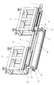
도 3은 도 2에 도시된 이송장치의 로딩수단의 사시도.3 is a perspective view of the loading means of the transfer device shown in FIG.
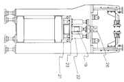
도 4는 도 2의 본 발명에 따른 이송장치를 펀넬검사장치에 사용한 실시예의 정면도.Figure 4 is a front view of an embodiment using the transfer device according to the invention of Figure 2 in the funnel inspection apparatus.
도 5는 도 4의 측면도.5 is a side view of FIG. 4.
* 도면의주요부분에대한부호의설명* Explanation of symbols on the main parts of the drawing
10: 검사장치 11: 콘베이어 12: 베이스 플레이트 13: 로딩수단 14,15: 프레임 17: 서보모터 18: 볼스크류 19,22: 공압실린더 20: 제 1 마운트 21: 가이드레일 23: 제 2 마운트 26: 지지부재 27: 블록 28: 롤러 31: 펀넬 32: 센서DESCRIPTION OF
상기 목적을 달성하기 위한 본 발명의 이송장치는 가공 또는 측정장치의 양측에 설치되어 작업대로 부품을 송급하도록 모터로 구동되는 다수의 롤러를 구비한 이송수단과, 상기 작업대 양측의 이송수단 밑에 각각 설치된 프레임에 왕복운동 및 승하강하도록 장착되어 상기 이송수단으로 부터 송급되는 부품을 작업대의 소정위치에 로딩시키고 또한 작업완료된 부품은 작업대로 부터 후속공정을 위하여 이송수단에 언로딩시키는 로딩수단을 포함하며, 상기 로딩수단은 일측의 프레임에 장착된 서보모터에 의해 구동되는 볼스크류와 맞물려 볼스크류의 회전방향에 따라 왕복운동하는 제 1마운트와, 타측의 프레임에 이격되어 고정된 가이드레일에서 슬라이드하도록 장착되고 상기 제 1마운트와 연결부재로 연결되어 함께 이동하는 제 2마운트, 상기 마운트들 각각에 장착된 실린더의 피스톤로드의 상단에 단부가 고정되고 작업대 위에 가로질러 배치되어 부품을 지지하는 지지부재를 포함하여 구성된다.The conveying apparatus of the present invention for achieving the above object is provided on both sides of the processing or measuring device is provided with a conveying means having a plurality of rollers driven by a motor to supply parts to the workbench, respectively installed under the conveying means on both sides of the workbench It is mounted to the frame reciprocating and ascending and descending to load the parts fed from the conveying means to a predetermined position of the workbench and the finished part includes a loading means for unloading the conveying means for the subsequent process from the workbench, The loading means is mounted to slide in a guide rail fixed to the first mount and reciprocating in accordance with the rotation direction of the ball screw in engagement with the ball screw driven by a servo motor mounted to one frame, and fixed to the other frame A second mount connected to the first mount and a connection member and moving together; The end at the top of the piston rod of the cylinder mounted to the respective fixed teudeul disposed across over the work surface it consists of a support member for supporting the parts.
이하에서는 본 발명의 실시예를 도시한 첨부도면을 참고하여 본 발명을 상세히 설명하기로 한다.Hereinafter, with reference to the accompanying drawings showing an embodiment of the present invention will be described in detail the present invention.
본 발명 이송장치는 여러 분야에서 부품을, 예를들어 가공장치 또는 검사장치의 베이스 플레이트와 같은 작업대로 송급하는데 사용할 수 있으나, 본 실시예에서는 브라운관 벌브생산 공정에서 펀넬에 접합된 넥크의 접합상태를 검사하도록 검사할 펀넬을 검사장치에 로딩하고 검사완료후 다시 이송수단에 언로딩하기 위해 채용한 경우에 대하여 설명하기로 한다.The conveying device of the present invention can be used to supply parts in various fields, for example, a workbench such as a base plate of a processing device or an inspection device. However, in the present embodiment, the connection state of the neck bonded to the funnel in the CRT bulb production process is described. A case in which the funnel to be inspected for inspection is employed to load the inspection apparatus and to unload the conveying means again after completion of the inspection will be described.
도 2는 본 발명에 따른 이송장치(10)를 도시하고 있으며, 도 3에는 도 2의 로딩수단을 사시도로서 도시하고 있다. 작업대로서 펀넬 검사장치의 양측에 설치되어 펀넬을 이송수단인 콘베이어(11)로 부터 검사장치의 베이스 플레이트(12)에 로딩하고 검사완료된 펀넬을 후속공정으로 송급하는 콘베이어(11)에 언로딩하는 로딩수단(13)이 제공된 상태를 보여 준다.Figure 2 shows a
상기 로딩수단(13)은 도 3에 사시도로 도시되어 있으며, 송급측 프레임(14)은 검사를 위한 펀넬을 검사장치로 송급하는 측면에 설치되며, 배출측 프레임(15)은 검사장치에서 검사완료된 펀넬을 후속공정을 위해 배출하는 측면에 설치된다. 상기 프레임(14,15)들은 고정용 빔(16)에 의해 서로 연결되어 있다.The
배출측 프레임(15)의 상면 일단부에는 정역회전가능한 서보모터(17)가 장착되어 있으며, 그 출력축에는 브라켓에 의해 지지된 볼스크류(18)가 연결되고, 상기 볼스크류(18)에는 상면에 공압실린더(19)가 수직으로 세워져 고정된 제 1 마운트(20)가 장착된다. 상기 송급측 프레임(14)의 상면에는 서로 이격된 2개의 가이드레일(21)이 고정되고, 가이드레일(21)에는 상면에 2개의 공압실린더(22)가 이격되어 고정된 제 2 마운트(23)가 슬라이드가능하게 장착되어 있다. 상기 제 1 및 제 2 마운트(20.23)들은 연결부재(24)에 의해 연결되어 일체로 움직이도록 되어 있다.A
상기 공압실린더(19,22)들의 피스톤로드에는 브라켓(25)에 의해 빔형태로 된 2개의 이격된 지지부재(26)가 그 양단부 저면이 고정되어 있다. 이로써, 상기 지지부재(26)는 공압실린더(19,22) 작동시 피스톤로드과 함께 승하강되며, 또한 서보모터(17)의 작동에 의해 제 1 마운트(20)가 볼스크류(18)와 맞물려 수평으로 왕복운동하고 제 1 마운트(20)와 연결부재(24)로 연결된 제 2 마운트(22)도 가이드레일(21)에서 함께 왕복운동함에 따라 지지부재(26)는 전진 및 후퇴이동하게 된다. 상기 지지부재(26)의 하강된 위치는 검사장치의 베이스 플레이트(12)의 상면에 인접하여 블록(27)보다 낮게 배치됨과 함께 검사장치에 인접한 콘베이어(11)에 구비된 롤러(28)의 상면보다 낮으며, 승강된 위치는 지지부재(26)의 상면이 상기 롤러(28)와 베이스 플레이트에 제공된 블럭(27)의 상면보다 약간 높게 배치되는 위치이다. 특히, 상기 롤러(28)들중 지지부재(26)의 이동범위에 있는 롤러들은 지지부재가 롤러 위아래로 승하강할 수 있도록 서로 이격되어 회전하도록 장착된 2개의 롤러부분(28')으로 이루어지며 각 롤러부분들은 인접한 롤러부분들과 벨트와 같은 전동수단으로 연결되고 그중 하나는 롤러(28)와 연결되어 전체적으로 함께 구동된다.On the piston rods of the
상기한 서보모터(17)와 공압실린더(19,22)들의 작동은 콘베이어(11)의 물품인입측 단부에 제공된 센서(32)의 신호에 응답하여 작동하되, 이송수단으로서의 콘베이어(11)의 이송속도와 같게 그리고 베이스 플레이트(12)에서의 검사 또는 가공에 소요되는 시간만큼 지연되어 순차적으로 이루어지도록 미리 설정되어 있다.The operation of the
상기와 같은 구성의 본 발명에 의한 이송장치의 작용을 도 4 와 도 5를 참고하여 설명하기로 한다. 도 4는 본 발명의 이송장치(10)를 브라운관용 벌브 생산을 위한 펀넬 검사공정에 채용한 사용상태를 보여주고 있으며, 도 5은 도 4의 측면도이다. 도면에서 펀넬 검사장치는, 전공정에서 펀넬에 넥크를 접합하고 그 접합부의 스트레스를 제거하기 위하여 어닐링한 다음, 펀넬을 이송하여 펀넬의 중심선에 대하여 넥크의 편심도와 기울기가 미리 설정한 허용오차의 범위에 포함되는지를 검사하여 불량여부를 판정하기 위한 것이다.An operation of the transfer apparatus according to the present invention having the above configuration will be described with reference to FIGS. 4 and 5. Figure 4 shows the state of use of the
전공정에서 넥크가 펀넬에 융착되고 어닐링작업완료된 다음 펀넬은 콘베이어(11)를 통해 검사장치의 베이스 플레이트(12)로 송급된다. 상기 펀넬은 콘베이어(11)의 프레임에 일정 간격을 두고 배치되어 모터에 의해 구동되는 롤러(28) 위에 배치되어 이송된다. 검사장치에 인접한 위치의 콘베이어(11)에서는 중앙부에서 펀넬 지지부재(26)가 왕복운동가능하게 공간을 형성하도록 길이가 짧은 롤러부분(28')들이 이격되어 프레임의 양측에 배치되어 있고, 특히 펀넬 인입측에는 가이드부재(30)가 설치되어 검사장치로 인입되는 펀넬(31)이 도 4에 가상선으로 도시된 바와같이 콘베이어의 중앙에 배치된다. 이때, 프레임(29)의 측부에 장착된 센서(32)에 의해 펀넬(31)이 도착했음을 감지하여 신호를 발생하면 공압실린더(19,22)들이 작동하여 피스톤들이 전진됨에 따라 지지부재(26)는 초기에 콘베이어의 롤러부분(28') 상면 보다 낮은 위치에서 검사장치의 베이스플레이트(12)에 고정된 블록(27) 보다 위로 돌출되게 승강되어 콘베이어의 롤러에 의해 지지되던 펀넬이 지지부재에 얹혀 지지된다. 그런다음, 서보모터(17)가 작동하여 회전되는 볼스크류(18)와 맞물린 제 1 마운트(20)가 잠기는 방향으로, 즉 도면에서 좌측으로 이동함에 따라 그와 일체로 연결된 제 2 마운트(23)가 가이드레일(21)에서 슬라이드되어 상기 지지부재(26)는 수평이동하여 펀넬(31)이 검사장치의 베이스플레이트(12)의 블럭(27) 위에 위치할 때 서보모터(17)가 동작정지되고, 이어서 공압실린더(19,22)의 피스톤로드가 후퇴하여 지지부재(26)가 블럭(27) 상면보다 낮게 하강함에 따라 펀넬(31)이 베이스플레이트(12)의 블럭(27)에 로딩되어 검사장치에서 펀넬 넥크의 접합상태 검사작업이 수행된다.In the previous step, the neck is fused to the funnel and the annealing operation is completed, and then the funnel is fed to the
상기 펀넬검사작업이 종료되면, 공압실린더(19,22)의 피스톤로드가 다시 전진하여 지지부재(26)가 승강되어 검사된 펀넬이 베이스플레이트(12)의 블록(27)으로 부터 들어올려져 지지부재(26)에 얹히게 된다. 이 상태에서 서보모터(17)가 작동하여 볼스크류(18)가 계속 회전하여 제 1 마운트(20)를 잠기는 방향으로 계속 이동함에 따라 제 2 마운트(23)가 도면에서 좌측으로 더욱 이동하고, 검사된 펀넬이 배출측 콘베이어 위에 위치하게 되면, 서보모터(17)는 정지하고 공압실린더(19,22)의 피스톤로드는 하강하여 지지부재(26)가 롤러부분(28')의 상면보다 낮게 위치함에 따라 그에 얹힌 펀넬이 롤러부분(28')에 놓여지며, 이때 롤러가 구동하여 다음 공정으로 펀넬을 이송하게 된다. 한편, 지지부재(26)는 하강된 상태에서 서보모터(17)가 다시 역회전하여 제 1 마운트(20)가 볼스크류(18)로 부터 풀리는 방향으로, 즉 도면에서 우측으로 이동하고 제 2 마운트(23)도 우측으로 이동함에 따라 지지부재(26)가 검사장치로 이송할 펀넬이 배치된 롤러부분(28')의 밑에 위치하는 초기상태로 된다. 본 발명의 로딩수단이 전술한 바와같은 동작을 반복함에 따라 콘베이어(11)를 통해 송급되는 펀넬을 자동으로 검사장치에 로딩하고 검사완료후에 다시 배출측 콘베이어로 언로딩하게 된다.When the funnel inspection operation is completed, the piston rods of the
본 실시예에서는, 본 발명의 이송장치를 브라운관용 벌브생산공정에서 펀넬의 검사장치의 베이스 플레이트에 펀넬을 자동으로 로딩하기 위하여 채용한 경우에 대하여 설명되었으나, 본 발명은 여기에 한정되지 않고 다른 검사장치 또는 가공장치의 베이스 플레이트와 같은 작업대에 가공 또는 검사할 물품을 자동으로 이송 및 로딩하는데 이용될 수 있다.In the present embodiment, the case where the transfer device of the present invention is adopted to automatically load the funnel to the base plate of the inspection device of the funnel in the bulb production process for CRT, has been described, but the present invention is not limited to this and other inspection It can be used to automatically transport and load articles to be processed or inspected on a workbench, such as a base plate of an apparatus or processing apparatus.
본 발명에 따라, 펀넬을 지지하는 지지부재(26)와, 지지부재와 결합되어 승하강시키는 공압실린더(19,22) 및 서보모터(17)에 의해 회전되는 볼스크류(18)와 맞물려 전진 또는 후진하는 제 1 마운트(20)와 그에 종동하는 제 2 마운트(23)를 포함하여, 지지부재(26)를 승강시켜 수평이동시킴으로써 넥크의 접합상태를 검사할 펀넬을 콘베이어의 롤러부분(28')로 부터 검사장치의 베이스 플레이트(12)의 블록(27)에 로딩하고, 검사작업이 완료되면 펀넬을 다시 후속공정으로 송급하기 위해 지지부재(26)를 승강시킨 다음 수평이동시켜 베이스 플레이트의 블럭으로부터 펀넬(31)을 언로딩시키고 지지부재가 다시 하강하여 펀넬을 콘베이어의 롤러부분(28')에 내려놓는 전과정이 미리 정해진 시퀀스에 따라 작업자의 도움없이 자동적으로 수행되므로 인력이 절감되어 생산비를 낮출 수 있고, 종래 작업자의 실수에 의한 펀넬의 손상이 방지되며, 펀넬의 로딩 및 언로딩공정의 자동화로 검사장치로의 펀넬송급 및 후속공정으로의 배출이 신속하게 이루어져 생산성이 향상되는 효과가 있다.According to the present invention, the
Claims (5)
Priority Applications (1)
| Application Number | Priority Date | Filing Date | Title |
|---|---|---|---|
| KR1019970024932A KR100200062B1 (en) | 1997-06-16 | 1997-06-16 | Feeding device with loading means |
Applications Claiming Priority (1)
| Application Number | Priority Date | Filing Date | Title |
|---|---|---|---|
| KR1019970024932A KR100200062B1 (en) | 1997-06-16 | 1997-06-16 | Feeding device with loading means |
Publications (2)
| Publication Number | Publication Date |
|---|---|
| KR19990001560A KR19990001560A (en) | 1999-01-15 |
| KR100200062B1 true KR100200062B1 (en) | 1999-06-15 |
Family
ID=19509729
Family Applications (1)
| Application Number | Title | Priority Date | Filing Date |
|---|---|---|---|
| KR1019970024932A KR100200062B1 (en) | 1997-06-16 | 1997-06-16 | Feeding device with loading means |
Country Status (1)
| Country | Link |
|---|---|
| KR (1) | KR100200062B1 (en) |
Cited By (2)
| Publication number | Priority date | Publication date | Assignee | Title |
|---|---|---|---|---|
| KR101218198B1 (en) | 2011-08-12 | 2013-01-03 | (주)로봇플러스 | Robot handling system |
| KR101305409B1 (en) | 2011-06-30 | 2013-09-06 | 안병열 | Supply device of parts |
Families Citing this family (2)
| Publication number | Priority date | Publication date | Assignee | Title |
|---|---|---|---|---|
| KR100923904B1 (en) * | 2002-10-23 | 2009-10-28 | (주)에이스안테나 | Apparatus being able to manufacture multiple workplace |
| CN108381273A (en) * | 2018-04-28 | 2018-08-10 | 牧野机床(中国)有限公司 | A kind of handling equipment |
-
1997
- 1997-06-16 KR KR1019970024932A patent/KR100200062B1/en not_active IP Right Cessation
Cited By (2)
| Publication number | Priority date | Publication date | Assignee | Title |
|---|---|---|---|---|
| KR101305409B1 (en) | 2011-06-30 | 2013-09-06 | 안병열 | Supply device of parts |
| KR101218198B1 (en) | 2011-08-12 | 2013-01-03 | (주)로봇플러스 | Robot handling system |
Also Published As
| Publication number | Publication date |
|---|---|
| KR19990001560A (en) | 1999-01-15 |
Similar Documents
| Publication | Publication Date | Title |
|---|---|---|
| JPH06262456A (en) | Circulating automatic assembling work station device | |
| CN113731849B (en) | Handling equipment for conveying goods | |
| KR101559349B1 (en) | An arranging apparatus for transporting tires | |
| KR100200062B1 (en) | Feeding device with loading means | |
| JPH06198483A (en) | Laser beam machining device | |
| CN109201775A (en) | The online vision inspection apparatus of punching parts defect and method | |
| CN112122838B (en) | Full-automatic welding device for box type house | |
| CN107298306B (en) | Feeding device | |
| US5454466A (en) | Accumulating conveyor | |
| CN217807419U (en) | Transfer frame device and glass transfer system | |
| CN212558327U (en) | Automatic feeding measuring device | |
| JPH0686246B2 (en) | Lower parts supply device for vehicle assembly line | |
| CN210995341U (en) | Commodity circulation letter sorting scanning device | |
| CN207580242U (en) | Glassware boxing system | |
| JPS6250376B2 (en) | ||
| JPH0662241B2 (en) | Loading device for press parts | |
| JP4020768B2 (en) | Assembling apparatus and assembling method for lower body parts | |
| CN215945800U (en) | Conveying equipment for objects | |
| JPH0318118Y2 (en) | ||
| CN218950466U (en) | Automatic discharging stacking device for large-specification wooden or bamboo profiles | |
| CN219116547U (en) | Conveyer and transformer production line | |
| CN220299643U (en) | Plant oil drum conveying device | |
| KR920009294B1 (en) | Device for transferring pallet used in conveyor system | |
| JPH0116719B2 (en) | ||
| JPS6283970A (en) | Automatic loading device |
Legal Events
| Date | Code | Title | Description |
|---|---|---|---|
| A201 | Request for examination | ||
| E701 | Decision to grant or registration of patent right | ||
| GRNT | Written decision to grant | ||
| FPAY | Annual fee payment |
Payment date: 20050218 Year of fee payment: 7 |
|
| LAPS | Lapse due to unpaid annual fee |