JP7694397B2 - Rotor manufacturing method - Google Patents
Rotor manufacturing method Download PDFInfo
- Publication number
- JP7694397B2 JP7694397B2 JP2022001728A JP2022001728A JP7694397B2 JP 7694397 B2 JP7694397 B2 JP 7694397B2 JP 2022001728 A JP2022001728 A JP 2022001728A JP 2022001728 A JP2022001728 A JP 2022001728A JP 7694397 B2 JP7694397 B2 JP 7694397B2
- Authority
- JP
- Japan
- Prior art keywords
- short
- circuit ring
- rod
- rotor
- shaped portion
- Prior art date
- Legal status (The legal status is an assumption and is not a legal conclusion. Google has not performed a legal analysis and makes no representation as to the accuracy of the status listed.)
- Active
Links
Images


Classifications
-
- Y—GENERAL TAGGING OF NEW TECHNOLOGICAL DEVELOPMENTS; GENERAL TAGGING OF CROSS-SECTIONAL TECHNOLOGIES SPANNING OVER SEVERAL SECTIONS OF THE IPC; TECHNICAL SUBJECTS COVERED BY FORMER USPC CROSS-REFERENCE ART COLLECTIONS [XRACs] AND DIGESTS
- Y02—TECHNOLOGIES OR APPLICATIONS FOR MITIGATION OR ADAPTATION AGAINST CLIMATE CHANGE
- Y02T—CLIMATE CHANGE MITIGATION TECHNOLOGIES RELATED TO TRANSPORTATION
- Y02T10/00—Road transport of goods or passengers
- Y02T10/60—Other road transportation technologies with climate change mitigation effect
- Y02T10/64—Electric machine technologies in electromobility
Landscapes
- Manufacture Of Motors, Generators (AREA)
Description
本発明は、回転子の製造方法に関する。 The present invention relates to a method for manufacturing a rotor.
従来、回転子鉄心の両端に配置した短絡環と、この短絡環を接続する棒状部とをかご状に組み合わせた回転子を有するかご形誘導電動機が知られている。このようなかご形誘導電機における回転子として、鋳造によって成形された短絡環や棒状部を有する態様が知られている(例えば、特許文献1参照)。 Conventionally, there is known a cage induction motor having a rotor in which short-circuit rings arranged at both ends of the rotor core and rod-shaped portions that connect the short-circuit rings are combined in a cage shape. A known embodiment of the rotor in such a cage induction motor has short-circuit rings and rod-shaped portions formed by casting (see, for example, Patent Document 1).
しかしながら、棒状部と短絡環とを鋳造によって成形する場合、棒状部や短絡環に鋳巣と称される空洞が形成される場合がある。鋳巣は電気抵抗を高めることから、棒状部や短絡環の電気抵抗を高める。このため、棒状部と短絡環を鋳造によって成形した回転子を備えたかご形誘導電動機を稼働させた場合、回転子が鋳巣に起因して発熱することが考えられる。 However, when the rod-shaped portion and the short-circuit ring are formed by casting, cavities called blowholes may form in the rod-shaped portion and the short-circuit ring. Blobs increase the electrical resistance, and therefore increase the electrical resistance of the rod-shaped portion and the short-circuit ring. For this reason, when a squirrel-cage induction motor equipped with a rotor in which the rod-shaped portion and the short-circuit ring are formed by casting is operated, it is conceivable that the rotor will generate heat due to the blowholes.
そこで、本明細書開示の発明は、かご形誘導電動機の稼働時の発熱を抑制可能な回転子を得ることができる製造方法を提供することを課題とする。 Therefore, the objective of the invention disclosed in this specification is to provide a manufacturing method that can obtain a rotor that can suppress heat generation during operation of a squirrel-cage induction motor.
本明細書開示の回転子の製造方法は、回転子鉄心の回転軸に沿う方向の一端側に配置された第1短絡環と、前記回転子鉄心を隔てて前記第1短絡環と対向させて配置された第2短絡環と、前記回転子鉄心に挿通されて前記第1短絡環と前記第2短絡環とを接続する複数の棒状部と、を備えた回転子の製造方法であって、導電性を有する材料塊を押圧し、前記第1短絡環と当該第1短絡環から延びる前記棒状部を成形する成形工程と、前記棒状部に、当該棒状部の自由端部側から前記回転子鉄心を挿入する挿入工程と、前記回転子鉄心が挿入された後の前記棒状部の前記自由端部に前記第2短絡環を設ける加工工程と、を含む。 The method of manufacturing a rotor disclosed in this specification is a method of manufacturing a rotor having a first short-circuit ring arranged on one end side in the direction along the rotation axis of the rotor core, a second short-circuit ring arranged facing the first short-circuit ring across the rotor core, and a plurality of rod-shaped parts that are inserted into the rotor core to connect the first short-circuit ring and the second short-circuit ring, and includes a forming process of pressing a conductive material block to form the first short-circuit ring and the rod-shaped parts extending from the first short-circuit ring, an inserting process of inserting the rotor core into the rod-shaped parts from the free end side of the rod-shaped parts, and a processing process of providing the second short-circuit ring at the free end of the rod-shaped parts after the rotor core is inserted.
上記の回転子の製造方法において、導電性を有する筒状の材料塊の側壁を押圧することにより、前記第1短絡環および前記棒状部を形成する、態様とすることができる。 In the above rotor manufacturing method, the first short-circuit ring and the rod-shaped portion can be formed by pressing the side wall of a cylindrical conductive block of material.
また、上記の回転子の製造方法において、前記成形工程は、導電性を有する中実柱状の材料塊を押圧し、底板部と環状壁部とを有する中間体を形成する第一工程と、前記底板部を除去して前記第1短絡環を形成する第二工程と、前記環状壁部を櫛歯状に加工し、前記棒状部を形成する第三工程と、を有する態様とすることができる。 In addition, in the rotor manufacturing method described above, the forming process can include a first process of pressing a conductive solid columnar material block to form an intermediate body having a bottom plate portion and an annular wall portion, a second process of removing the bottom plate portion to form the first short-circuit ring, and a third process of processing the annular wall portion into a comb-tooth shape to form the rod-shaped portion.
上記の回転子の製造方法において、前記第三工程は、前記棒状部として形成される部分に隣接して設定された除去部分を除去する、態様とすることができる。 In the above rotor manufacturing method, the third step may be configured to remove a removal portion that is set adjacent to the portion formed as the rod-shaped portion.
前記除去部分は、切削工具によって切削除去する、態様とすることができる。 The removed portion may be cut and removed using a cutting tool.
上記の回転子の製造方法において、前記第2短絡環を設ける工程は、前記回転子鉄心から突出した前記自由端部を周方向に折り曲げ、周方向に隣接する前記自由端部同士を接触状態として前記第2短絡環を設ける、態様とすることができる。 In the rotor manufacturing method described above, the step of providing the second short-circuit ring can be performed by bending the free end protruding from the rotor core in the circumferential direction, and providing the second short-circuit ring with the free end portions adjacent in the circumferential direction in contact with each other.
さらに、上記の回転子の製造方法において、前記第2短絡環を設ける工程は、前記回転子鉄心から突出した前記自由端部に接触させて導電性を有する板体を載置し、前記自由端部と前記板体との接触箇所を溶接する、態様とすることもできる。 Furthermore, in the rotor manufacturing method described above, the step of providing the second short-circuit ring can be performed by placing a conductive plate in contact with the free end protruding from the rotor core, and welding the contact point between the free end and the plate.
本明細書開示の発明は、かご形誘導電動機の稼働時の発熱を抑制可能な回転子を得ることができる製造方法を提供することができる。 The invention disclosed in this specification can provide a manufacturing method that can obtain a rotor that can suppress heat generation during operation of a squirrel-cage induction motor.
以下、本発明の実施形態について、添付図面を参照しつつ説明する。ただし、図面中、各部の寸法、比率等は、実際のものと完全に一致するようには図示されていない場合がある。また、図面によっては細部が省略されて描かれている場合もある。さらに、各図に描かれている各要素の縮尺が異なっている場合がある。 Below, an embodiment of the present invention will be described with reference to the attached drawings. However, the dimensions, ratios, etc. of each part in the drawings may not be illustrated to be exactly the same as the actual ones. Also, some details may be omitted in some drawings. Furthermore, the scale of each element depicted in each drawing may differ.
(第1実施形態)
[かご形誘導電動機の構成]
まず、図1を参照して、本実施形態の製造方法によって製造された回転子4が組み込まれたかご形誘導電動機1の概略構成について説明する。かご形誘導電動機1は、例えば、エンジンと走行用モータとを車両の駆動源として搭載したハイブリッド車両や、電気自動車、燃料電池車等の電動車両の走行モータや、ポンプやファンの駆動源として用いられる。
First Embodiment
[Configuration of a squirrel-cage induction motor]
First, a schematic configuration of a squirrel-
かご形誘導電動機1は、ケース2内に設けられた環状の固定子3と、固定子3内に固定子3と径方向に対向配置された回転子4を備える。回転子4は、固定子3内で回転軸AX回りに回転可能に設けられている。回転子4は、回転子鉄心5の回転軸AX方向に沿う方向の一端側に配置された第1短絡環6と、回転子鉄心5を隔てて第1短絡環6と対向させて配置された第2短絡環7を備える。また、回転子4は、第1短絡環6と第2短絡環7とを接続する複数の棒状部8を備える。回転子鉄心5の中央部には、回転軸部材9が設けられており、この回転軸部材9は、回転子4の一端側に設けられた第1軸受部材10aと、回転子4の他端側に設けられた第2軸受部材10bとによってケース2に支持されている。これにより、回転子4は、回転することができる。なお、本実施形態では、図3(H)に示すように、棒状部8は、周方向に配列され、その数は、12本とされているが、棒状部8の数は、これに限定されるものではなく、その他の本数であってもよい。
The
[製造方法]
以下、回転子4の製造方法について説明する。
<押出成形工程>
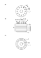
回転子4の製造方法は、押出成形工程を含む。図2は、押出成形工程で用いられるパンチ20を示している。パンチ20は、ピン形状の工具であり、その先端部に、円柱状のガイド部21を備えている。また、パンチ20は、ガイド部211よりも基端側にガイド部21よりも直径が大きい段差部22を備えている。段差部22の高さは、第1短絡環6の厚さに対応させて設定されている。パンチ20は、段差部22よりも基端側に径方向に突出している複数の突状部23と、周方向に隣接する突状部23の間に形成されている溝状部24とを備えている。突状部23と溝状部24とは、周方向に沿って交互に設けられており、いずれもパンチ20の長手方向に沿って延びている。後に詳細に説明するように、溝状部24に材料塊40(図3(A)等参照)の一部が流動して入り込むことで、棒状部8(図1参照)が形成される。
[Manufacturing method]
A method for manufacturing the
<Extrusion molding process>
The manufacturing method of the
つぎに、図3(A)を参照すると、押出成形は、パンチ20とダイ30とを用いて実施される。ダイ30は、パンチ20が備えるガイド部21が挿し込まれる第1収納凹部31と、パンチ20の段差部22、突状部23及び溝状部24が形成されている部分が挿し込まれる第2収納凹部32を備えている。第2収納凹部32の内周径は、第1収納凹部31の内周径よりも大きく、パンチ20の突状部23が摺接することができる寸法に設定されている。
Next, referring to FIG. 3(A), extrusion molding is performed using a
作業者は、まず、このようなダイ30の第2収納凹部32内に導電性を有する筒状の材料塊40をセットする。材料塊40は、図3(B)や図3(C)に示すように、筒状とされている。本実施形態における材料塊40は、純銅(タフピッチ銅)によって形成されているが、僅かに不純物を含んでいてもよい。また、材料塊40は、導電性を有するとともに、塑性変形をすることができる加工性を備えた材料の中から適宜選定することができる。銅以外に、例えば、アルミニウム、金、銀、銅合金、アルミニウム合金等の中から適宜選定することができる。
First, the worker sets a cylindrical conductive lump of
作業者は、図3(A)に示すように、ダイ30の第2収納凹部32に材料塊40をセットし、その後、パンチ20をダイ30内に挿入する。そして、作業者は、図3(D)に示す矢示15aのように、パンチ20を移動させて材料塊40を押圧する。これにより、材料塊40は、図3(F)における矢示15bのように、パンチ20の押圧方向とは逆方向に押し広げられ、第2収納凹部32内において、パンチ20とダイ30との間に形成されている空間内に流れ込む。この結果、材料塊40は、図3(E)や図3(F)に示すように徐々にその形状を変化させる。なお、材料塊40を押出成形する際、材料塊40の体積は成形の前後において変化することはない。
As shown in FIG. 3(A), the worker sets the
図3(D)に示す状態から、作業者が図3(G)に示す矢示15cのようにパンチ20をさらに押し込むと、材料塊40は、図3(I)における矢示15dのように、パンチ20の押圧方向とは逆方向にさらに押し広げられる。そして、パンチ20の段差部22がダイ30の第1収納凹部31と第2収納凹部32との境界部分にまで到達すると、図3(H)や図3(I)に示すように、環状の第1短絡環6と、第1短絡環6と連設部8aにおいて連設された状態で延びる複数の棒状部8とが一度に形成される。棒状部8の連設部8aと反対側の端部は、自由端部8bとされている。第1短絡環6や棒状部8は、押出成形によって形成されているため、これを鋳造によって形成する場合と異なり、これらの部分に鋳巣が生じることがない。
When the worker presses the
本実施形態では、鋳巣の発生を回避するために塑性変形を利用した加工を採用しており、塑性変形を利用した加工の中でも、押出成形を採用している。塑性変形を利用した加工としては、例えば、プレス加工が知られているが、プレス加工であると、棒状部8に必要な長さ寸法を確保することが困難となる。つまり、プレス加工であると、材料に対する引っ張り工程が含まれるが、引っ張り工程では、長尺部分の形成が困難である。これに対し、押出成形であれば、棒状部8の必要な長さ寸法を確保することができる。
In this embodiment, processing using plastic deformation is used to avoid the occurrence of blowholes, and among the processing using plastic deformation, extrusion molding is used. Press processing is known as a processing using plastic deformation, for example, but with press processing, it is difficult to ensure the required length dimension for the rod-shaped
<挿入工程>
押出成形工程が終了した後は、挿入工程に移行する。挿入工程は、押出成形工程によって形成された棒状部8の自由端部8b側から回転子鉄心5を挿入する工程である。作業者は、複数枚の板状の電磁鋼板5aを積層することによって回転子鉄心5を形成する。図4に電磁鋼板5aの平面図を示す。1枚の電磁鋼板5aは、ケイ素鋼板によって円盤状に形成されており、その中心部に回転軸部材9(図1参照)を挿通させるための第1挿通孔5a1が設けられている。また、第1挿通孔5a1の周囲に、周方向に所定の間隔を空けて第2挿通孔5a2が設けられている。第2挿通孔5a2には、それぞれ棒状部8が挿通される。このため、第2挿通孔5a2の配置は、棒状部8の配置に応じて設定されている。なお、電磁鋼板5a自体は、従来周知のものであり、その製造方法についても、従来知られている方法を採用することができるので、ここでは、その詳細な説明は省略する。
<Insertion process>
After the extrusion molding process is completed, the process proceeds to the insertion process. In the insertion process, the
本実施形態では、棒状部8を挿通させるために、第2挿通孔5a2が設けられているが、第2挿通孔5a2に代えて、電磁鋼板5aの外周縁側が開放された切欠きを設けるようにしてもよい。
In this embodiment, a second insertion hole 5a2 is provided to allow the rod-shaped
挿入工程では、図5(A)から図5(C)に示すように、棒状部8が、その自由端部8b、つまり、第1短絡環6が設けられている側とは反対側から第2挿通孔5a2に挿し込まれる。挿し込まれた電磁鋼板5aは、第1短絡環6上に順次積層される。すべての電磁鋼板5aが挿し込まれた後、最上部の電磁鋼板5aの上方には、図5(B)に示すように棒状部8の自由端部8bが突出した状態となっている。なお、図5(B)には描画の都合上、6枚の電磁鋼板5aが積層された状態が描かれているが、これは、実際の積層数を示すものではない。
In the insertion process, as shown in Fig. 5(A) to Fig. 5(C), the rod-shaped
<短絡環形成工程>
つぎに、第2短絡環7を形成する短絡環形成工程について説明する。図5(B)に示したように、すべての電磁鋼板5aが挿し込まれた後、最上部の電磁鋼板5aの上方には、棒状部8の自由端部8bが突出している。短絡環形成工程では、作業者は、この自由端部8bに折り曲げ加工を施す。具体的に、図6において矢示15eで示すように、作業者は、自由端部8bに横方向から力を加えて自由端部8bを周方向に折り曲げ、周方向に隣接する自由端部8b同士を接触状態とさせる。これにより、自由端部8bが周状に折り重なった状態となり、第2短絡環7が形成される。なお、自由端部8b同士が接触している部分には、ロウ付けを施して強度を向上させてもよい。
<Short-circuit ring formation step>
Next, the short-circuit ring forming process for forming the second short-
自由端部8bは、元々材料塊40(図3(B)等参照)から押出成形されて形成されているため、自由端部8bにも鋳巣が生じることはなく、第2短絡環7においても発熱が抑制される。
The
以上により、回転子4が形成される。形成された回転子4には、圧入によって回転軸部材9が装着され、図1に示すように、固定子3内に組み込まれる。なお、回転軸部材9の装着は、焼き嵌めや接着剤による固定、溶接等、従来公知の方法を採用することができる。
The
第1実施形態の回転子4の製造方法によれば、第1短絡環6、第2短絡環7及び棒状部8が押出成形によって形成されているため、例えば、これらを鋳造によって形成した場合と異なり、鋳巣が生じることがない。この結果、かご形誘導電動機1の稼働時の発熱が抑制される。
According to the manufacturing method of the
なお、本実施形態では、各工程は、作業者が行うものとして説明したが、各工程は、作業機を用いて自動で実施されるようにしてもよい。この点は、以下に説明する第2実施形態及び第3実施形態においても共通する。 In this embodiment, each process is described as being performed by a worker, but each process may be performed automatically using a work machine. This point is also common to the second and third embodiments described below.
(第2実施形態)
つぎに、図8から図11(B)を参照して、第2実施形態の製造方法について、説明する。第2実施形態の製造方法によって製造される回転子は、細部を除いて、第1実施形態の製造法によって製造された回転子4と共通するため、共通する構成要素について、同一の参照番号を用いて説明する。
Second Embodiment
Next, the manufacturing method of the second embodiment will be described with reference to Fig. 8 to Fig. 11 (B). The rotor manufactured by the manufacturing method of the second embodiment is common to the
<中間体形成工程>
第2実施形態における回転子4の製造方法は、中間体形成工程を含む。作業者は、中間体形成工程において、図9(F)に示すような中間体71を形成する。中間体71とは、第1短絡環6と棒状部8とを備えた形態に至る以前に形成される態様を指す。中間体の形成にも押出成形が採用される。図8は、中間体形成工程における押出成形で用いられるパンチ50を示している。パンチ50は、円柱形状の工具であり、円柱状部51とその基端部に形成されたテーパ部52を備えている。
<Intermediate formation process>
The manufacturing method of the
つぎに、図9(A)を参照すると、押出成形は、パンチ50とダイ60とを用いて実施される。ダイ60は、収納凹部61と、この収納凹部61の開口部上縁端に設けられたストッパ部62を備えている。収納凹部61の内周径は、パンチ50の円柱状部51の直径よりも大きい寸法を備えている。収納凹部61と円柱状部51との間の隙間の距離は、後に説明する中間体71の環状壁部71bの厚さ、ひいては、棒状部8の径方向の寸法に相当する。ストッパ部62は、パンチ50が押し込まれたときに、テーパ部52が当接することで、パンチ50の押し込み量を規定する。パンチ50の押し込み量は、後に説明する中間体71の底板部71aの厚さに応じて設定されている。
9(A), the extrusion molding is performed using a
まず、このようなダイ60の収納凹部61内に導電性を有する中実柱状の材料塊70をセットする。材料塊70は、図9(B)や図9(C)に示すように、中実柱状とされている。本実施形態における材料塊70は、第1実施形態の材料塊40と同様の材料で形成されている。
First, a conductive solid columnar lump of
図9(A)に示すように、作業者は、ダイ60の収納凹部61に材料塊70をセットし、その後、パンチ50をダイ60内に挿入する。そして、作業者は、図9(D)に示す矢示15fのように、パンチ50を移動させて材料塊40を押圧する。これにより、材料塊70は、パンチ50の押圧方向とは逆方向に押し広げられ、収納凹部61内において、パンチ50とダイ60との間に形成されている空間内に流れ込む。これにより、材料塊70は、徐々にその形状を変化させ、最終的に、図9(E)や図9(F)に示すような中間体71に変化する。
As shown in FIG. 9(A), the worker sets the lump of
中間体71は、コップ形状を有しており、底板部71aと底板部71aの縁部から延設されて立ち上がった環状壁部71bを備えている。
<打ち抜き工程>
つぎに、図10(A)から図10(E)を参照して、打ち抜き工程について説明する。打ち抜き工程は、中間体71の底板部71aから打ち抜き片71a1を打ち抜き、第1短絡環6を形成する工程である。作業者は、まず、図10(A)に示す矢示15gのように、底板部71aに対向させて配置した打ち抜きパンチ80を底板部71aに接近させる。そして、作業者は、図10(B)における矢示15hのように打ち抜きパンチ80を底板部71aに押し当てて、打ち抜き片71a1を打ち抜く。これにより、開口部71a2が形成され、環状の第1短絡環6が形成される。なお、打ち抜き工程によって打ち抜き片71a1を打ち抜くことで、第1短絡環6には鍔状部6aが形成されるが、この鍔状部6aは、切削加工等で除去してもよいし、そのまま、残置した状態としておいてもよい。第2実施形態は、この鍔状部6aが形成される点で第1実施形態と異なる。
The
<Punching process>
Next, the punching process will be described with reference to Fig. 10(A) to Fig. 10(E). The punching process is a process of punching a punched piece 71a1 from the
なお、本実施形態では、底板部71aの加工に打ち抜き加工を採用しているが、切削加工や、切り抜き加工等の加工方法を採用してもよい。
In this embodiment, punching is used to process the
<機械加工工程>
つぎに、機械加工工程について、説明する。機械加工工程は、中間体71の環状壁部71bを櫛歯状に加工し、棒状部8を形成する工程である。図11(A)及び図11(B)を参照すると、棒状部8として形成される部分に隣接して設定された除去部分71b1が網掛けを付して示されている。本実施形態では、この除去部分71b1を図11(B)に示す切削工具81によって、切削し、除去する。これにより、図10(D)や図10(E)に示すように第1短絡環6と棒状部8を備えた状態とすることができる。つまり、機械加工を施すことで、第1実施形態において、図3(H)や図3(I)に示す状態と同等の状態を実現することができる。
<Machining process>
Next, the machining process will be described. The machining process is a process in which the
なお、本実施形態では、機械加工として切削加工を採用しているが、打ち抜き加工や、切り抜き加工等、従来公知の他の加工方法を採用してもよい。また、本実施形態では、打ち抜き加工の後に機械加工工程を実施しているが、これらの順番は問わず、順番を入れ替えてもよいし、同時に両方の加工を実施するようにしてもよい。 In this embodiment, cutting is used as the machining process, but other conventionally known machining methods such as punching and cutting may also be used. Also, in this embodiment, the machining process is performed after punching, but the order of these steps does not matter, and the order may be reversed, or both processes may be performed at the same time.
<挿入工程>
作業者は、打ち抜き工程及び機械加工工程の後、挿入工程を実施する。挿入工程については、第1実施形態と同様であるので、ここでは、その詳細な説明は省略する。
<Insertion process>
After the punching and machining processes, the worker performs the insertion process. The insertion process is the same as that in the first embodiment, so a detailed description thereof will be omitted here.
<短絡環形成工程>
作業者は、挿入工程の後、短絡環形成工程を実施する。短絡環形成工程については、第1実施形態と同様であるので、ここでは、その詳細な説明は省略する。
<Short-circuit ring formation step>
After the insertion step, the worker performs the short-circuit loop forming step. The short-circuit loop forming step is the same as that in the first embodiment, and therefore a detailed description thereof will be omitted here.
第2実施形態の製造方法であっても、第1短絡環6及び棒状部8が押出成形によって形成されているため、例えば、これらを鋳造によって形成した場合と異なり、鋳巣が生じることがない。この結果、かご形誘導電動機1の稼働時の発熱が抑制される。
Even in the manufacturing method of the second embodiment, the first short-
(第3実施形態)
つぎに、第3実施形態について図12(A)及び図12(B)を参照して説明する。第3実施形態の製造方法は、第1実施形態や第2実施形態と比較して、短絡環形成工程が異なる。
Third Embodiment
Next, a third embodiment will be described with reference to Fig. 12(A) and Fig. 12(B) The manufacturing method of the third embodiment is different from the first and second embodiments in the short-circuiting ring forming step.
第1実施形態や第2実施形態では、棒状部8の自由端部8bを折り曲げることで第2短絡環7を形成した。これに対し、第3実施形態の製造方法によって製造される回転子90は、導電性を有する板体、本実施形態にあっては銅板によって形成された第2短絡環91を備えている。第2短絡環91は、回転子鉄心5から突出した棒状部8の自由端部8bに接触させて銅板を載置し、接触箇所を溶接することで形成される。
In the first and second embodiments, the second short-
このような回転子90であっても、第1短絡環6と棒状部8は、第1実施形態や第2実施形態における工程と同様の工程を経ることによって形成される。このため、第1短絡環6及び棒状部8が押出成形によって形成されているため、例えば、これらを鋳造によって形成した場合と異なり、鋳巣が生じることがない。この結果、かご形誘導電動機1の稼働時の発熱が抑制される。
Even in such a
上記実施形態は本発明を実施するための例にすぎず、本発明はこれらに限定されるものではなく、これらの実施例を種々変形することは本発明の範囲内であり、更に本発明の範囲内において、他の様々な実施例が可能であることは上記記載から自明である。 The above embodiments are merely examples for implementing the present invention, and the present invention is not limited to these. Various modifications of these embodiments are within the scope of the present invention. Furthermore, it is self-evident from the above description that various other embodiments are possible within the scope of the present invention.
1 かご形誘導電動機 2 ケース
3 固定子 4 回転子
5 回転子鉄心 5a 電磁鋼板
5a1 第1挿通孔 5a2 第2挿通孔
6 第1短絡環 6a 鍔状部
7 第2短絡環 8 棒状部
8a 連設部 8b 自由端部
9 回転軸部材 10a 第1軸受部材
10b 第2軸受部材 20、50 パンチ
21 ガイド部 22 段差部
23 突状部 24 溝状部
30、60 ダイ 31 第1収納凹部
32 第2収納凹部 40、70 材料塊
51 円柱状部 52 テーパ部
61 収納凹部 62 ストッパ部
71 中間体 71a 底板部
71a1 打ち抜き片 71a2 開口部
71b 環状壁部 71b1 除去部分
80 打ち抜きパンチ 81 切削工具
REFERENCE SIGNS
Claims (6)
導電性を有する材料塊を押圧し、前記第1短絡環と当該第1短絡環から延びる前記棒状部を成形する成形工程と、
前記棒状部に、当該棒状部の自由端部側から前記回転子鉄心を挿入する挿入工程と、
前記回転子鉄心が挿入された後の前記棒状部の前記自由端部に前記第2短絡環を設ける加工工程と、
を含み、
前記成形工程は、導電性を有する筒状の材料塊の側壁を押圧することにより、前記第1短絡環および前記棒状部を形成する、
回転子の製造方法。 A method for manufacturing a rotor including a first short-circuit ring arranged on one end side in a direction along a rotation axis of a rotor core, a second short-circuit ring arranged opposite to the first short-circuit ring across the rotor core, and a plurality of rod-shaped portions that are inserted into the rotor core to connect the first short-circuit ring and the second short-circuit ring,
a molding step of pressing a conductive material block to form the first short-circuit ring and the rod-shaped portion extending from the first short-circuit ring;
an insertion step of inserting the rotor core into the rod-shaped portion from a free end side of the rod-shaped portion;
a processing step of providing the second short-circuit ring at the free end of the rod-shaped portion after the rotor core is inserted;
Including,
The forming step forms the first short-circuit ring and the rod-shaped portion by pressing a side wall of a cylindrical conductive material block.
Manufacturing method of the rotor.
導電性を有する材料塊を押圧し、前記第1短絡環と当該第1短絡環から延びる前記棒状部を成形する成形工程と、
前記棒状部に、当該棒状部の自由端部側から前記回転子鉄心を挿入する挿入工程と、
前記回転子鉄心が挿入された後の前記棒状部の前記自由端部に前記第2短絡環を設ける加工工程と、
を含み、
前記成形工程は、導電性を有する中実柱状の材料塊を押圧し、底板部と環状壁部とを有する中間体を形成する第一工程と、
前記底板部を除去して前記第1短絡環を形成する第二工程と、
前記環状壁部を櫛歯状に加工し、前記棒状部を形成する第三工程と、を有する回転子の製造方法。 A method for manufacturing a rotor including a first short-circuit ring arranged on one end side in a direction along a rotation axis of a rotor core, a second short-circuit ring arranged opposite to the first short-circuit ring across the rotor core, and a plurality of rod-shaped portions that are inserted into the rotor core to connect the first short-circuit ring and the second short-circuit ring,
a molding step of pressing a conductive material block to form the first short-circuit ring and the rod-shaped portion extending from the first short-circuit ring;
an insertion step of inserting the rotor core into the rod-shaped portion from a free end side of the rod-shaped portion;
a processing step of providing the second short-circuit ring at the free end of the rod-shaped portion after the rotor core is inserted;
Including,
The forming step includes a first step of pressing a conductive solid columnar material block to form an intermediate body having a bottom plate portion and an annular wall portion;
a second step of removing the bottom plate portion to form the first short-circuit ring;
and a third step of processing the annular wall portion into a comb-tooth shape to form the rod-shaped portion .
前記棒状部として形成される部分に隣接して設定された除去部分を除去する、
請求項2に記載の回転子の製造方法。
The third step comprises:
removing a removal portion set adjacent to the portion formed as the rod-shaped portion;
A method for manufacturing a rotor according to claim 2 .
請求項3に記載の回転子の製造方法。 The removed portion is cut and removed by a cutting tool.
The method for manufacturing the rotor according to claim 3 .
前記回転子鉄心から突出した前記自由端部を周方向に折り曲げ、周方向に隣接する前記自由端部同士を接触状態として前記第2短絡環を設ける、
請求項1又は2に記載の回転子の製造方法。 The processing step includes:
the free end portions protruding from the rotor core are bent in a circumferential direction, and the free end portions adjacent to each other in the circumferential direction are brought into contact with each other to provide the second short-circuit ring.
A method for manufacturing a rotor according to claim 1 or 2 .
前記回転子鉄心から突出した前記自由端部に接触させて導電性を有する板体を載置し、前記自由端部と前記板体との接触箇所を溶接する、
請求項1又は2に記載の回転子の製造方法。 The processing step includes:
a conductive plate is placed in contact with the free end protruding from the rotor core, and a contact portion between the free end and the plate is welded.
A method for manufacturing a rotor according to claim 1 or 2 .
Priority Applications (1)
| Application Number | Priority Date | Filing Date | Title |
|---|---|---|---|
| JP2022001728A JP7694397B2 (en) | 2022-01-07 | 2022-01-07 | Rotor manufacturing method |
Applications Claiming Priority (1)
| Application Number | Priority Date | Filing Date | Title |
|---|---|---|---|
| JP2022001728A JP7694397B2 (en) | 2022-01-07 | 2022-01-07 | Rotor manufacturing method |
Publications (2)
| Publication Number | Publication Date |
|---|---|
| JP2023101232A JP2023101232A (en) | 2023-07-20 |
| JP7694397B2 true JP7694397B2 (en) | 2025-06-18 |
Family
ID=87201727
Family Applications (1)
| Application Number | Title | Priority Date | Filing Date |
|---|---|---|---|
| JP2022001728A Active JP7694397B2 (en) | 2022-01-07 | 2022-01-07 | Rotor manufacturing method |
Country Status (1)
| Country | Link |
|---|---|
| JP (1) | JP7694397B2 (en) |
Citations (2)
| Publication number | Priority date | Publication date | Assignee | Title |
|---|---|---|---|---|
| JP2001186734A (en) | 1999-11-10 | 2001-07-06 | Korea Advanced Inst Of Sci Technol | Cage-shaped rotor using polymer resin containing high investment rate powder and method of manufacturing the same |
| JP2012222863A (en) | 2011-04-04 | 2012-11-12 | Fanuc Ltd | Squirrel-cage rotor and manufacturing method thereof |
Family Cites Families (5)
| Publication number | Priority date | Publication date | Assignee | Title |
|---|---|---|---|---|
| JPS5825537U (en) * | 1981-08-11 | 1983-02-18 | 三菱電機株式会社 | squirrel cage rotor |
| JPH0698510A (en) * | 1992-09-16 | 1994-04-08 | Hitachi Ltd | Rotor for induction motor |
| JPH08214516A (en) * | 1995-02-06 | 1996-08-20 | Toshiba Corp | Cage type rotor and its manufacturing method |
| JPH1032966A (en) * | 1996-07-12 | 1998-02-03 | Hitachi Ltd | Induction motor rotor |
| JPH1175330A (en) * | 1997-08-29 | 1999-03-16 | Matsushita Electric Ind Co Ltd | Rotor and manufacturing method thereof |
-
2022
- 2022-01-07 JP JP2022001728A patent/JP7694397B2/en active Active
Patent Citations (2)
| Publication number | Priority date | Publication date | Assignee | Title |
|---|---|---|---|---|
| JP2001186734A (en) | 1999-11-10 | 2001-07-06 | Korea Advanced Inst Of Sci Technol | Cage-shaped rotor using polymer resin containing high investment rate powder and method of manufacturing the same |
| JP2012222863A (en) | 2011-04-04 | 2012-11-12 | Fanuc Ltd | Squirrel-cage rotor and manufacturing method thereof |
Also Published As
| Publication number | Publication date |
|---|---|
| JP2023101232A (en) | 2023-07-20 |
Similar Documents
| Publication | Publication Date | Title |
|---|---|---|
| CN107404201B (en) | Manufacturing method of laminated core | |
| JP3656733B2 (en) | Stator for rotating electrical machine for vehicle and method for manufacturing the same | |
| US20050050714A1 (en) | Manufacturing method for a motor layered core, manufacturing apparatus thereof, and stacking jig thereof | |
| US7986072B2 (en) | Stator core of electric rotating machine and method of manufacturing the core | |
| JP2016214000A (en) | Manufacturing method of laminated iron core processed body and manufacturing method of laminated iron core | |
| JP4886375B2 (en) | Laminated core manufacturing method | |
| JPWO2018062003A1 (en) | Method of manufacturing laminated core | |
| JP3294348B2 (en) | Manufacturing method of laminated core | |
| CN111033979B (en) | Method and apparatus for manufacturing stator core, motor, and method for manufacturing laminated member | |
| JP6288201B1 (en) | Method for punching electromagnetic steel sheet and method for manufacturing laminated iron core | |
| JP5055020B2 (en) | Linked laminated core, armature manufacturing method, and progressive mold apparatus | |
| EP2690752A1 (en) | Stator core manufacturing method | |
| JP7694397B2 (en) | Rotor manufacturing method | |
| JP4333641B2 (en) | Stator manufacturing method for rotating electrical machine | |
| JP5536493B2 (en) | Manufacturing method and manufacturing apparatus of laminated iron core | |
| JP6655409B2 (en) | Laminated core and method of manufacturing laminated core | |
| JP6834899B2 (en) | Manufacturing method of rotary electric core | |
| JP5484130B2 (en) | Manufacturing method and manufacturing apparatus of laminated iron core | |
| JP5248972B2 (en) | Method for manufacturing laminated iron core and mold apparatus | |
| JPH06133501A (en) | Electric motor stator laminated core and manufacturing method thereof | |
| JP2016153131A (en) | Mold device and metal product manufacturing method using same | |
| JP5964221B2 (en) | Armature manufacturing method and progressive mold apparatus | |
| JP4989877B2 (en) | Manufacturing method of rotor laminated core | |
| CN118923025A (en) | Method for manufacturing stator core, and motor | |
| CN111033982B (en) | Stator core manufacturing method |
Legal Events
| Date | Code | Title | Description |
|---|---|---|---|
| A621 | Written request for application examination |
Free format text: JAPANESE INTERMEDIATE CODE: A621 Effective date: 20240320 |
|
| A131 | Notification of reasons for refusal |
Free format text: JAPANESE INTERMEDIATE CODE: A131 Effective date: 20241210 |
|
| A977 | Report on retrieval |
Free format text: JAPANESE INTERMEDIATE CODE: A971007 Effective date: 20241212 |
|
| A521 | Request for written amendment filed |
Free format text: JAPANESE INTERMEDIATE CODE: A523 Effective date: 20250204 |
|
| RD02 | Notification of acceptance of power of attorney |
Free format text: JAPANESE INTERMEDIATE CODE: A7422 Effective date: 20250204 |
|
| RD04 | Notification of resignation of power of attorney |
Free format text: JAPANESE INTERMEDIATE CODE: A7424 Effective date: 20250204 |
|
| TRDD | Decision of grant or rejection written | ||
| A01 | Written decision to grant a patent or to grant a registration (utility model) |
Free format text: JAPANESE INTERMEDIATE CODE: A01 Effective date: 20250507 |
|
| A61 | First payment of annual fees (during grant procedure) |
Free format text: JAPANESE INTERMEDIATE CODE: A61 Effective date: 20250520 |
|
| R150 | Certificate of patent or registration of utility model |
Ref document number: 7694397 Country of ref document: JP Free format text: JAPANESE INTERMEDIATE CODE: R150 |