JP7691925B2 - Electric pot - Google Patents
Electric pot Download PDFInfo
- Publication number
- JP7691925B2 JP7691925B2 JP2021520424A JP2021520424A JP7691925B2 JP 7691925 B2 JP7691925 B2 JP 7691925B2 JP 2021520424 A JP2021520424 A JP 2021520424A JP 2021520424 A JP2021520424 A JP 2021520424A JP 7691925 B2 JP7691925 B2 JP 7691925B2
- Authority
- JP
- Japan
- Prior art keywords
- electrode
- main body
- housing
- electric heating
- heating pot
- Prior art date
- Legal status (The legal status is an assumption and is not a legal conclusion. Google has not performed a legal analysis and makes no representation as to the accuracy of the status listed.)
- Active
Links
Images


Classifications
-
- A—HUMAN NECESSITIES
- A47—FURNITURE; DOMESTIC ARTICLES OR APPLIANCES; COFFEE MILLS; SPICE MILLS; SUCTION CLEANERS IN GENERAL
- A47J—KITCHEN EQUIPMENT; COFFEE MILLS; SPICE MILLS; APPARATUS FOR MAKING BEVERAGES
- A47J27/00—Cooking-vessels
- A47J27/21—Water-boiling vessels, e.g. kettles
- A47J27/21008—Water-boiling vessels, e.g. kettles electrically heated
- A47J27/2105—Water-boiling vessels, e.g. kettles electrically heated of the cordless type, i.e. whereby the water vessel can be plugged into an electrically-powered base element
-
- A—HUMAN NECESSITIES
- A47—FURNITURE; DOMESTIC ARTICLES OR APPLIANCES; COFFEE MILLS; SPICE MILLS; SUCTION CLEANERS IN GENERAL
- A47J—KITCHEN EQUIPMENT; COFFEE MILLS; SPICE MILLS; APPARATUS FOR MAKING BEVERAGES
- A47J27/00—Cooking-vessels
- A47J27/21—Water-boiling vessels, e.g. kettles
- A47J27/21008—Water-boiling vessels, e.g. kettles electrically heated
- A47J27/21041—Water-boiling vessels, e.g. kettles electrically heated with heating elements arranged outside the water vessel
-
- A—HUMAN NECESSITIES
- A47—FURNITURE; DOMESTIC ARTICLES OR APPLIANCES; COFFEE MILLS; SPICE MILLS; SUCTION CLEANERS IN GENERAL
- A47J—KITCHEN EQUIPMENT; COFFEE MILLS; SPICE MILLS; APPARATUS FOR MAKING BEVERAGES
- A47J27/00—Cooking-vessels
- A47J27/21—Water-boiling vessels, e.g. kettles
- A47J27/21166—Constructional details or accessories
-
- H—ELECTRICITY
- H05—ELECTRIC TECHNIQUES NOT OTHERWISE PROVIDED FOR
- H05B—ELECTRIC HEATING; ELECTRIC LIGHT SOURCES NOT OTHERWISE PROVIDED FOR; CIRCUIT ARRANGEMENTS FOR ELECTRIC LIGHT SOURCES, IN GENERAL
- H05B3/00—Ohmic-resistance heating
- H05B3/0004—Devices wherein the heating current flows through the material to be heated
-
- H—ELECTRICITY
- H05—ELECTRIC TECHNIQUES NOT OTHERWISE PROVIDED FOR
- H05B—ELECTRIC HEATING; ELECTRIC LIGHT SOURCES NOT OTHERWISE PROVIDED FOR; CIRCUIT ARRANGEMENTS FOR ELECTRIC LIGHT SOURCES, IN GENERAL
- H05B3/00—Ohmic-resistance heating
- H05B3/0014—Devices wherein the heating current flows through particular resistances
-
- H—ELECTRICITY
- H05—ELECTRIC TECHNIQUES NOT OTHERWISE PROVIDED FOR
- H05B—ELECTRIC HEATING; ELECTRIC LIGHT SOURCES NOT OTHERWISE PROVIDED FOR; CIRCUIT ARRANGEMENTS FOR ELECTRIC LIGHT SOURCES, IN GENERAL
- H05B3/00—Ohmic-resistance heating
- H05B3/60—Heating arrangements wherein the heating current flows through granular powdered or fluid material, e.g. for salt-bath furnace, electrolytic heating
-
- H—ELECTRICITY
- H05—ELECTRIC TECHNIQUES NOT OTHERWISE PROVIDED FOR
- H05B—ELECTRIC HEATING; ELECTRIC LIGHT SOURCES NOT OTHERWISE PROVIDED FOR; CIRCUIT ARRANGEMENTS FOR ELECTRIC LIGHT SOURCES, IN GENERAL
- H05B3/00—Ohmic-resistance heating
- H05B3/68—Heating arrangements specially adapted for cooking plates or analogous hot-plates
- H05B3/681—Plates having mobile parts coming into contact with the bottom of the kettles, pans, or the like
-
- H—ELECTRICITY
- H05—ELECTRIC TECHNIQUES NOT OTHERWISE PROVIDED FOR
- H05B—ELECTRIC HEATING; ELECTRIC LIGHT SOURCES NOT OTHERWISE PROVIDED FOR; CIRCUIT ARRANGEMENTS FOR ELECTRIC LIGHT SOURCES, IN GENERAL
- H05B3/00—Ohmic-resistance heating
- H05B3/78—Heating arrangements specially adapted for immersion heating
- H05B3/80—Portable immersion heaters
-
- H—ELECTRICITY
- H05—ELECTRIC TECHNIQUES NOT OTHERWISE PROVIDED FOR
- H05B—ELECTRIC HEATING; ELECTRIC LIGHT SOURCES NOT OTHERWISE PROVIDED FOR; CIRCUIT ARRANGEMENTS FOR ELECTRIC LIGHT SOURCES, IN GENERAL
- H05B2203/00—Aspects relating to Ohmic resistive heating covered by group H05B3/00
- H05B2203/021—Heaters specially adapted for heating liquids
-
- Y—GENERAL TAGGING OF NEW TECHNOLOGICAL DEVELOPMENTS; GENERAL TAGGING OF CROSS-SECTIONAL TECHNOLOGIES SPANNING OVER SEVERAL SECTIONS OF THE IPC; TECHNICAL SUBJECTS COVERED BY FORMER USPC CROSS-REFERENCE ART COLLECTIONS [XRACs] AND DIGESTS
- Y02—TECHNOLOGIES OR APPLICATIONS FOR MITIGATION OR ADAPTATION AGAINST CLIMATE CHANGE
- Y02E—REDUCTION OF GREENHOUSE GAS [GHG] EMISSIONS, RELATED TO ENERGY GENERATION, TRANSMISSION OR DISTRIBUTION
- Y02E60/00—Enabling technologies; Technologies with a potential or indirect contribution to GHG emissions mitigation
- Y02E60/30—Hydrogen technology
- Y02E60/36—Hydrogen production from non-carbon containing sources, e.g. by water electrolysis
Landscapes
- Engineering & Computer Science (AREA)
- Food Science & Technology (AREA)
- Cookers (AREA)
- Water Treatment By Electricity Or Magnetism (AREA)
- Resistance Heating (AREA)
Description
本発明は、電熱ポットに関するものである。 The present invention relates to an electric heating pot.
ユーザーのニーズに応じて、液体、例えば水を加熱する様々な電熱ポットが販売されており、さらに、これを改善する様々な研究および開発が行われている。 Depending on the needs of users, various electric heating pots that heat liquids, such as water, are available on the market, and various research and development efforts are being conducted to further improve them.
特に生活水準の向上により、様々な用途のために加熱された液体、例えば温水が使用されている。 Particularly as living standards improve, heated liquids, such as hot water, are used for a variety of purposes.
また、産業化や技術の進歩に伴い、個人の生活パターンが変化し、時間の活用が重要になった。従って、電熱ポットを利用した簡単な方法で液体を加熱することが広く利用されている。 In addition, with the advancement of industrialization and technology, the life patterns of individuals have changed and time management has become important. Therefore, the simple method of heating liquids using electric heating pots has become widely used.
しかし、ユーザーの利便性および安全性を向上させ、電熱ポットの効率を向上させる技術を実装することには限界がある。 However, there are limitations to implementing technology that improves user convenience and safety and increases the efficiency of electric heating pots.
本発明は、電気的安定性およびユーザーの利便性を向上させ、効率を上げることができる電熱ポットを提供することを目的とする。 The present invention aims to provide an electric heating pot that can improve electrical stability and user convenience, and increase efficiency.
本発明の一様相は、本体部と、本体部に熱を提供する加熱部とを含む電熱ポットに関するものであり、本体部は、液体を収容する収容空間を含み、加熱部は、電解水が内部に配置されるように形成されるハウジングと、ハウジング内に配置され、ハウジング内で少なくとも一領域が電解水と接触するように形成される複数の電極を含む電極部とを含む電熱ポットが開示される。 One aspect of the present invention relates to an electric heating pot that includes a main body and a heating unit that provides heat to the main body. The main body includes a storage space that stores liquid, and the heating unit includes a housing that is formed so that electrolyzed water is placed inside, and an electrode unit that is disposed within the housing and includes a plurality of electrodes that are formed so that at least one area within the housing comes into contact with the electrolyzed water.
一実施形態において、本体部および加熱部は互いに分離可能に形成されてもよい。 In one embodiment, the main body portion and the heating portion may be formed so as to be separable from each other.
一実施形態において、ハウジングの少なくとも一領域は絶縁材料を含んでもよい。 In one embodiment, at least a region of the housing may include an insulating material.
一実施形態において、複数の電極のそれぞれの延長された端部は、ハウジングの内側面と離間して形成されてもよい。 In one embodiment, the extended ends of each of the multiple electrodes may be spaced apart from the inner surface of the housing.
一実施形態において、ハウジングは、本体部に向いた上面部、および本体部の反対に向いた底部を含み、さらに電極部の複数の電極は、上面部と底部と離間して形成されてもよい。 In one embodiment, the housing includes a top surface facing the main body portion and a bottom surface facing away from the main body portion, and the electrodes of the electrode portion may be formed spaced apart from the top surface and the bottom surface.
一実施形態において、電極部は、曲線領域を含んでもよい。 In one embodiment, the electrode portion may include a curved region.
一実施形態において、電熱ポットは加熱部と本体部との間に配置された絶縁層をさらに含んでもよい。 In one embodiment, the electric heating pot may further include an insulating layer disposed between the heating portion and the body portion.
一実施形態において、電熱ポットは加熱部と本体部との間に配置された伝熱部をさらに含んでもよい。 In one embodiment, the electric heating pot may further include a heat transfer section disposed between the heating section and the main body section.
上述したこと以外の他の態様、特徴、および利点は、以下の図面、請求の範囲、および発明の詳細な説明から明らかであろう。 Other aspects, features, and advantages beyond those described above will be apparent from the following drawings, claims, and detailed description of the invention.
本発明に関する電熱ポットは、電気的安定性およびユーザーの利便性を向上させ、効率を上げることができる。 The electric heating pot of the present invention can improve electrical stability and user convenience, and increase efficiency.
以下に、添付された図面に示された本発明における実施形態を参照し、本発明の構成および作用を詳細に説明する。 The configuration and operation of the present invention will be described in detail below with reference to the embodiment of the present invention shown in the attached drawings.
本発明は、様々な変更および、様々な実施形態を有することができ、特定の実施形態を図面に例示し、詳細な説明に詳細に説明する。本発明の利点および特徴、さらに、それらを達成する方法は、図面を参照して、以下で説明する実施形態をから、より明確に理解されるであろう。しかしながら、本発明は、以下に開示される実施形態に限定されるものではなく、様々な形態で実現することができる。 The present invention can have various modifications and various embodiments, and specific embodiments are illustrated in the drawings and described in detail in the detailed description. The advantages and features of the present invention, as well as the methods of achieving them, will be more clearly understood from the embodiments described below with reference to the drawings. However, the present invention is not limited to the embodiments disclosed below, and can be realized in various forms.
以下で、本発明の実施形態を添付した図面を参照して詳細に説明するが、図面を参照して説明する際は、同一または対応する構成要素は、同一の図面番号を付与し、これに対する重複説明を省略するものとする。 Hereinafter, an embodiment of the present invention will be described in detail with reference to the attached drawings. When describing with reference to the drawings, the same or corresponding components will be given the same drawing numbers and duplicate descriptions thereof will be omitted.
以下の実施形態において、第1および第2などの用語は、全てにおいて限定的なものではなく、1つの構成要素を他の構成要素と区別するために使用する。 In the following embodiments, terms such as first and second are not limiting in any way and are used to distinguish one component from another.
以下の実施形態において、文脈が明確に示す場合を除き、単数形は複数形も含む。 In the following embodiments, the singular also includes the plural, unless the context clearly indicates otherwise.
以下の実施形態において、「含む」または「有する」などの用語は、明細書で開示されている特徴、または構成要素の存在を意味し、1つまたはそれ以上の他の特徴、または構成要素が付加される可能性を事前に排除するものではない。 In the following embodiments, terms such as "comprise" or "have" refer to the presence of features or components disclosed in the specification, and do not preclude the possibility that one or more other features or components may be added.
説明の便宜上、図面に示された構成要素の大きさは、拡大または縮小され得る。例えば、図面に示された各構成の大きさ、および厚さは、説明の便宜上、任意に示すものであり、本発明は、必ずしも図面に示されたものに限定されるものではない。 For convenience of explanation, the size of the components shown in the drawings may be enlarged or reduced. For example, the size and thickness of each component shown in the drawings are shown arbitrarily for convenience of explanation, and the present invention is not necessarily limited to those shown in the drawings.
以下の実施形態において、x軸、y軸、およびz軸は、直交座標系の3軸に限定されず、より広い意味で解釈されてもよい。例えば、x軸、y軸、およびz軸は、互いに直交していてもよく、互いに直交していない異なる方向をあらわしてもよい。 In the following embodiments, the x-axis, y-axis, and z-axis are not limited to the three axes of a Cartesian coordinate system, but may be interpreted in a broader sense. For example, the x-axis, y-axis, and z-axis may be mutually orthogonal, or may represent different directions that are not mutually orthogonal.
一実施形態において、異なる方法で実現可能である場合、特定の工程の順序は、説明される順序とは異なる順序で実行してもよい。例えば、連続して説明する2つの工程は、実質的には同時に実行してもよく、説明される順序とは逆の順序で実行してもよい。 In one embodiment, the order of certain steps may be performed in a different order than described if they can be accomplished in a different manner. For example, two steps described as successive may be performed substantially simultaneously or may be performed in the reverse order from that described.
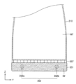
図1は、本発明の一実施形態における電熱ポットを示した概略正面図であり、図2は、図1のII-II線に沿って切り取った断面図であり、図3は、図1のIII-III線に沿って切り取った断面図であり、図4a、図4b、図4cは、図2におけるK、L、Mの変形例を示す拡大図である。 Figure 1 is a schematic front view of an electric heating pot in one embodiment of the present invention, Figure 2 is a cross-sectional view taken along line II-II in Figure 1, Figure 3 is a cross-sectional view taken along line III-III in Figure 1, and Figures 4a, 4b, and 4c are enlarged views showing modified examples of K, L, and M in Figure 2.
図1~図3を参照すると、一実施形態の電熱ポット100は、本体部110および加熱部150を含んでもよい。
Referring to Figures 1 to 3, one embodiment of the
本体部110は、一方向において加熱部150と隣接するように配置されてもよい。例えば、本体部110は、本体部110の長手方向において加熱部150と隣接するように配置されてもよい。
The
一実施形態において、本体部110と加熱部150とが互いに結合されるように形成されてもよい。例えば、本体部110と加熱部150とが、一体に形成されてもよい。また、本体部110と加熱部150は、互いに接触していてもよいし、あるいはその間に配置された中間部材と一体に形成されてもよい。
In one embodiment, the
一実施形態において、本体部110と加熱部150とは、分離可能に形成されてもよい。
In one embodiment, the
本体部110は、液体WTを収容するように構成された収容空間を含んでもよい。液体WTは、様々な種類の液体を含んでもよく、加熱部150によって加熱され得る様々な種類の液体を含んでもよい。例えば、液体WTは、水を含んでもよく、その場合、電熱ポット100は、水を加熱するためにユーザーによって使用されてもよい。
The
一実施形態において、液体WTを注ぐという動作により、本体部110の収容空間から液体WTが排出される出口部112が、本体部110の収容空間と連通するように形成されてもよい。
In one embodiment, the
一実施形態において、電熱ポット100の取り扱いを容易にするように、本体部110の一領域に取っ手部117が形成されてもよい。また、ユーザーが電熱ポット100の動作を選択的に制御するように、取っ手部117に、1つまたはそれ以上のボタン部材BPが形成されてもよい。ボタン部材BPは、取っ手部117と物理的に分離された形状を有するボタンであってもよく、一実施形態において、ボタン部材BPはディスプレイ部(図示せず)に表示されたボタンの形状を含んでもよい。
In one embodiment, a
加熱部150は、本体部110に熱を提供するように構成されてもよい。例えば、加熱部150は、本体部110の収容空間に収容された液体WTを加熱するように構成されてもよい。
The
加熱部150は、ハウジング151と、電極部152とを含んでもよい。
The
ハウジング151は、電解水IWを収容するように形成されてもよい。電解水IWは様々な種類の電解水IWを含んでもよい。例えば、電解水IWは、電解質溶液を含んでもよい。一実施形態において、電解水IWは様々な種類の電解質溶液の少なくとも1つが適切に希釈された蒸留水、ろ過水、ミネラルウオーター、水道水などを含んでもよい。
The
電解水IWに含まれている電解質物質としては、食用ソーダ、亜硝酸塩、ケイ酸塩、およびポリリン酸塩の無機物、アミン類およびオキシ酸類などを主成分とする防錆剤などを含む様々な種類を用いてもよい。 The electrolyte substances contained in the electrolytic water IW may be of various types, including inorganic substances such as edible soda, nitrites, silicates, and polyphosphates, and rust inhibitors whose main components are amines and oxyacids.
ハウジング151は、様々な形状を有してもよく、少なくとも電解水IWの出入りを制御するように構成されてもよい。例えば、ハウジング151は、電解水IWがハウジング151に充填された後、電解水IWがハウジング151の外部に流出しないように形成されてもよい。
The
一実施形態において、ハウジング151は、必要に応じて電解水IWを補充する補充流入部(図示せず)を含んでもよい。また、補充流入部とは別に、または補充流入部を利用して、電解水IWをハウジング151から排出した後に、電解水IWを新しいものと交換してもよい。または、ハウジング151内の空間に電解水IWが存在しない状態で、ハウジング151を保管、または修理などを行ってもよい。
In one embodiment, the
ハウジング151は、様々な材料を含んでもよい。例えば、ハウジング151は、耐久性のある材料を含んでもよく、例えば、金属材料を含んでもよい。
The
一実施形態において、ハウジング151は、絶縁材料を含んでもよい。例えば、ハウジング151は、樹脂やセラミックを含んでもよい。
In one embodiment, the
一実施形態において、ハウジング151は、フッ素樹脂であるテフロン(登録商標)樹脂を含んでもよい。
In one embodiment, the
一実施形態において、ハウジング151の面のうち、少なくとも電解水IWと隣接する内側面に絶縁層を含んでもよく、例えば、テフロン(登録商標)樹脂層を含んでもよい。テフロン(登録商標)樹脂層は、絶縁性テフロン(登録商標)層であってもよい。
In one embodiment, at least the inner surface of the
また、一実施形態において、ハウジング151の面のうち、電解水IWに隣接する内側面は、帯電防止テフロン(登録商標)樹脂層を含んでもよい。
In one embodiment, the inner surface of the
一実施形態において、ハウジング151は、本体部110の外形に類似した形状を有してもよく、例えば、円形に類似した形状の縁を有してもよい。
In one embodiment, the
一実施形態において、ハウジング151は、高さの低い柱状の形状を有してもよく、底部151aと、側面部151b、および上面部151cとを含んでもよい。
In one embodiment, the
電極部152は、ハウジング151内に配置されてもよく、その少なくとも一領域がハウジング内の電解水IWと接触するように形成されてもよく、また複数の電極を含んでもよい。
The
例えば、電極部152は、第1電極152aおよび第2電極152bを含んでもよい。
For example, the
第1電極152aおよび第2電極152bのそれぞれは、ハウジング151内の電解水IWと接触するように形成されてもよい。図示していないが、電極制御部(図示せず)の制御下で、第1電極152aおよび第2電極152bに電流が印加し、電極制御部(図示せず)を介して印加される電流を制御してもよい。
Each of the
電極部152の第1電極152aおよび第2電極152bに印加された電流によって、ハウジング151内の電解水IWが加熱されてもよい。電解水IWの熱は、収容空間内の液体WTを加熱するために、本体部110へ伝達されてもよい。
The electrolytic water IW in the
第1電極152aおよび第2電極152bは、互いに離間するように形成されてもよい。
The
例えば、第1電極152aおよび第2電極152bは、互いに所定の間隔で離間し、細長い形状を有してもよく、それぞれ直線的な形状を有してもよい。第1電極152aおよび第2電極152bのそれぞれから延在する各々の端部は、ハウジング151の領域、例えば、側面部151bから離間するように形成されてもよい。
For example, the
さらに、一実施形態において、第1電極152aおよび第2電極152bは、ハウジング151の底部151aと上面部151cから離間するように形成されてもよい。
Furthermore, in one embodiment, the
さらに、第1電極152aおよび第2電極152bの一領域と接続された導電部(図示せず)を含み、それにより第1電極152aおよび第2電極152bに電流が印加されてもよい。導電部(図示せず)は、ワイヤ状の導電線であり、電極制御部(図示せず)と接続されてもよい。一実施形態において、ハウジング151の外部に別途備えられてもよく、別の実施形態において、ハウジング151の一面に一体に形成されてもよい。
Furthermore, it may include a conductive portion (not shown) connected to a region of the
図示してはいないが、一実施形態において、電極部152は、3相の形態として3つの電極を含んでもよい。
Although not shown, in one embodiment, the
図4a、図4b、図4cは、図2のK、L、Mの変形例の拡大図を示す図である。 Figures 4a, 4b, and 4c are enlarged views of modified examples K, L, and M in Figure 2.
図4aを参照すると、一実施形態のハウジングの底部151a’は、外層部OLと、内層部ILとを含んでもよい。
Referring to FIG. 4a, the
外層部OLは、様々な材料、例えば、耐久性のある材料を含んでもよく、例えば、金属材料を含んでもよい。 The outer layer OL may include various materials, for example durable materials, for example metallic materials.
一実施形態において、外層部OLは、絶縁材料を含んでもよい。例えば、外層部OLは樹脂やセラミックを含んでもよい。 In one embodiment, the outer layer OL may include an insulating material. For example, the outer layer OL may include a resin or a ceramic.
内層部ILは、絶縁性材料を含んでもよい。例えば、内層部ILは、セラミック材料などの無機層を含んでもよい。一実施形態において、内層部ILは、樹脂層などの有機層を含んでもよい。 The inner layer IL may include an insulating material. For example, the inner layer IL may include an inorganic layer such as a ceramic material. In one embodiment, the inner layer IL may include an organic layer such as a resin layer.
さらに、一実施形態において、内層部は、絶縁性のテフロン(登録商標)層を含んでもよい。 Furthermore, in one embodiment, the inner layer may include an insulating Teflon (registered trademark) layer.
さらに、一実施形態において、内層部ILは、帯電防止のテフロン(登録商標)樹脂層を含んでもよい。 Furthermore, in one embodiment, the inner layer IL may include an antistatic Teflon (registered trademark) resin layer.
図4bを参照すると、一実施形態のハウジングの側面部151b’は、外層部OLと、内層部ILとを含んでもよい。
Referring to FIG. 4b, in one embodiment, the
外層部OLは、様々な材料を含んでもよく、例えば、耐久性のある材料を含んでもよく、一例として金属材料を含んでもよい。 The outer layer OL may include various materials, for example, a durable material, for example, a metal material.
一実施形態において、外層部OLは、絶縁材料を含んでもよい。例えば、外層部OLは、樹脂やセラミックを含んでもよい。 In one embodiment, the outer layer OL may include an insulating material. For example, the outer layer OL may include a resin or a ceramic.
内層部ILは、絶縁性材料を含んでもよい。例えば、内層部ILは、セラミック材料などの無機層を含んでもよい。一実施形態において、内層部ILは、樹脂層などの有機層を含んでもよい。 The inner layer IL may include an insulating material. For example, the inner layer IL may include an inorganic layer such as a ceramic material. In one embodiment, the inner layer IL may include an organic layer such as a resin layer.
さらに、一実施形態において、内層部ILは、絶縁性のテフロン(登録商標)層を含んでもよい。 Furthermore, in one embodiment, the inner layer IL may include an insulating Teflon (registered trademark) layer.
さらに、一実施形態において、内層部ILは、帯電防止のテフロン(登録商標)樹脂層を含んでもよい。 Furthermore, in one embodiment, the inner layer IL may include an antistatic Teflon (registered trademark) resin layer.
図4cを参照すると、一実施形態のハウジングの上面部151c’は、外層部OLと、内層部ILとを含んでもよい。
Referring to FIG. 4c, the
外層部OLは、様々な材料、例えば、耐久性のある材料を含んでもよく、一例として、金属材料を含んでもよい。 The outer layer OL may include various materials, such as durable materials, and may include, for example, a metal material.
一実施形態において、外層部OLは、絶縁材料を含んでもよい。例えば外層部OLは、樹脂やセラミックを含んでもよい。 In one embodiment, the outer layer OL may include an insulating material. For example, the outer layer OL may include a resin or a ceramic.
内層部ILは、絶縁性材料を含んでもよい。例えば、内層部ILは、セラミック材料などの無機層を含んでもよい。一実施形態において、内層部ILは、樹脂層などの有機層を含んでもよい。 The inner layer IL may include an insulating material. For example, the inner layer IL may include an inorganic layer such as a ceramic material. In one embodiment, the inner layer IL may include an organic layer such as a resin layer.
さらに、一実施形態において、内層部ILは、絶縁性のテフロン(登録商標)層を含んでもよい。 Furthermore, in one embodiment, the inner layer IL may include an insulating Teflon (registered trademark) layer.
さらに、一実施形態において、内層部ILは、帯電防止のテフロン(登録商標)樹脂層を含んでもよい。 Furthermore, in one embodiment, the inner layer IL may include an antistatic Teflon (registered trademark) resin layer.
一実施形態の電熱ポットは、加熱部の電極部の電極に印加する電流を制御することで、電解水を加熱することができる。電解水の熱は本体部に伝達され、本体部内の液体を加熱することができる。 In one embodiment, the electric heating pot can heat electrolyzed water by controlling the current applied to the electrodes of the electrode part of the heating unit. The heat of the electrolyzed water is transferred to the main body part, and the liquid inside the main body part can be heated.
したがって、電熱ポット内の液体を容易に加熱することができ、ユーザーの利便性を向上させることができる。例えば、ユーザーに温水を容易に供給することができる。 Therefore, the liquid in the electric heating pot can be easily heated, improving user convenience. For example, hot water can be easily supplied to the user.
さらに、選択的に、電極部の電極に印加する電流を容易に制御することで、電解水を安定的に加熱することができる。 Furthermore, by selectively and easily controlling the current applied to the electrodes of the electrode section, the electrolytic water can be heated stably.
さらに、電解水が配置されるハウジング、または少なくともハウジングの内側空間に外部への電流の漏れを低減または遮断するための、絶縁物質を含んでもよく、それにより安全で効率の高い電熱ポットを実現することができる。 Furthermore, the housing in which the electrolyzed water is placed, or at least the inner space of the housing, may contain an insulating material to reduce or block leakage of electric current to the outside, thereby achieving a safe and highly efficient electric heating pot.
さらに、電解水を加熱し、電解水の熱によって本体部内の液体を加熱することで、電熱ポットで本体部内の液体を直接加熱することによるリスクを低減することができる。 Furthermore, by heating the electrolyzed water and using the heat of the electrolyzed water to heat the liquid in the main body, the risks associated with directly heating the liquid in the main body with an electric heating pot can be reduced.
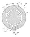
図5は、本発明の別の実施形態における電熱ポットを示した概略正面図であり、図6は、図5のVI-VI線に沿って切り取った断面図であり、図7は、図5のVII-VII線に沿って切り取った断面図である。 Figure 5 is a schematic front view showing an electric heating pot in another embodiment of the present invention, Figure 6 is a cross-sectional view taken along line VI-VI in Figure 5, and Figure 7 is a cross-sectional view taken along line VII-VII in Figure 5.
図5~図7を参照すると、一実施形態の電熱ポット200は、本体部210および加熱部250を含んでもよい。
Referring to Figures 5 to 7, one embodiment of the
本体部210は、一方向において、加熱部250と隣接するように配置されてもよい。例えば、本体部210の長手方向において加熱部250と隣接するように配置してもよい。
The
一実施形態において、本体部210と加熱部250とが互いに接続されるように形成されてもよい。例えば、本体部210と加熱部250が、一体に形成されてもよい。本体部210と加熱部250とが互いに接触してもよいし、あるいはその間に配置された中間部材と一体に形成されてもよい。
In one embodiment, the
一実施形態において、本体部210と加熱部250とは、互いに分離可能に形成されてもよい。
In one embodiment, the
本体部210は、液体WTを収容するように構成された収容空間を含んでもよい。液体WTは、様々な種類の液体を含んでもよく、加熱部250によって加熱され得る様々な種類の液体を含んでもよい。例えば、液体WTは、水を含んでもよく、その場合、電熱ポット200は、水を加熱するためにユーザーによって使用されてもよい。
The
一実施形態において、液体WTを注ぐという動作により、本体部110の収容空間から液体WTが排出される出口部112が、本体部110の収容空間と連通するように形成されてもよい。
In one embodiment, the
一実施形態において、電熱ポット200の取り扱いを容易にするように、本体部210の一領域に取っ手部217が形成されてもよい。また、ユーザーが電熱ポット200の動作を選択的に制御するように、取っ手部217に、1つまたはそれ以上のボタン部材BPが形成されてもよい。ボタン部材BPは、取っ手部217と物理的に分離された形状を有するボタンであってもよく、一実施形態において、ボタン部材BPはディスプレイ部(図示せず)に表示されたボタンの形状を含んでもよい。
In one embodiment, a
加熱部250は、本体部210に熱を提供するように構成されてもよい。例えば、加熱部250は、本体部210の収容空間に収容された液体WTを加熱するように形成されてもよい。
The
加熱部250は、ハウジング251と、電極部252とを含んでもよい。
The
ハウジング251は、電解水IWを収容するように形成されてもよい。電解水IWは様々な種類の電解水IWを含んでもよい。例えば、電解水IWは、電解質溶液を含んでもよい。一実施形態において、電解水IWは様々な種類の電解質溶液の少なくとも1つが適切に希釈された蒸留水、ろ過水、ミネラルウオーター、水道水などを含んでもよい。
The
電解水IWに含まれている電解質物質としては、食用ソーダ、亜硝酸塩、ケイ酸塩、およびポリリン酸塩の無機物、アミン類およびオキシ酸類などを主成分とする防錆剤などを含む様々な種類を用いてもよい。 The electrolyte substances contained in the electrolytic water IW may be of various types, including inorganic substances such as edible soda, nitrites, silicates, and polyphosphates, and rust inhibitors whose main components are amines and oxyacids.
前述したハウジング151の実施形態と同様にまたは類似して、ハウジング251に適用してもよく、一実施形態において、図4a~図4cの構造をハウジング251に適用してもよい。具体的な説明は、前述したものと同様であるので省略する。
The same or similar embodiment as the
電極部252は、ハウジング251内に配置されてもよく、その少なくとも一領域がハウジング内の電解水IWと接触するように形成されてもよく、また、複数の電極を含んでもよい。
The
例えば、電極部252は、第1電極252aおよび第2電極252bを含んでもよい。
For example, the
第1電極252aおよび第2電極252bのそれぞれは、ハウジング251内の電解水IWと接触するように形成されてもよい。図示していないが電極制御部(図示せず)の制御下で、第1電極252aおよび第2電極252bに電流が印加し、電極制御部(図示せず)を介して印加される電流が制御されてもよい。
Each of the
電極部252の第1電極252aおよび第2電極252bに印加された電流によって、ハウジング251内の電解水IWが加熱されてもよい。電解水IWの熱は、本体部210へ伝達され、収容空間内の液体WTを加熱してもよい。
The electrolytic water IW in the
第1電極252aおよび第2電極252bは、所定の間隔で互いに離間して形成されてもよい。
The
例えば、第1電極252aおよび第2電極252bは、それぞれ曲線領域を含んでもよい。
For example, the
第1電極252aを例に挙げて説明すると、第1電極252aは、曲線領域CPを含んでもよい。一実施形態において、第1電極252aは、曲線領域CPに接続され、引出領域を含む直線領域SPを含んでもよい。
Taking the
一実施形態において、曲線領域CPは、ハウジング251の縁に対応する形状の曲線領域を含んでもよく、半円または弧の形状を有してもよい。
In one embodiment, the curved region CP may include a curved region shaped to correspond to an edge of the
第2電極252bは、曲線領域を含んでもよい。一実施形態において、第2電極252bは、第1電極252aと対称の形状を有してもよい。
The
第1電極252aおよび第2電極252bの形状により、電極部252と電解水IWとの接触面積が増加し、ハウジング251内の電解水IWを均一に加熱する性能を向上させることができる。
The shape of the
第1電極252aおよび第2電極252bのそれぞれの曲線領域の端部は、ハウジング251の領域、例えば、側面部251bと離間するように形成されてもよい。
The ends of the curved regions of the
さらに、一実施形態において、第1電極252aおよび第2電極252bは、ハウジング251の底部251aと上面部251cから離間するように形成されてもよい。
Furthermore, in one embodiment, the
また、第1電極252aおよび第2電極252bに電流が印加されるように、第1電極252aおよび第2電極252bの一領域と接続された導電部(図示せず)を含んでもよい。導電部(図示せず)は、ワイヤ形状の導電線であってもよく、電極制御部(図示せず)に接続されてもよい。一実施形態において、導電部(図示せず)は、ハウジング251の外部に別に備えられてもよく、別の実施形態においてハウジング251の一面に一体に形成されてもよい。
The
図示してはいないが、一実施形態において、電極部252は、3相の形態として、3つの電極を含んでもよい。
Although not shown, in one embodiment, the
図8は、図7の変形例を示す図である。 Figure 8 shows a modified example of Figure 7.
図8を参照すると、電熱ポット200’は、本体部(図示せず)および加熱部を含んでもよい。 Referring to FIG. 8, the electric heating pot 200' may include a main body portion (not shown) and a heating portion.
加熱部は、支持部253’を含んでもよい。例えば、図8の電熱ポット200’は、図5~図7の電熱ポット200に支持部253’をさらに加えた形態であってもよい。
The heating section may include a support section 253'. For example, the electric heating pot 200' in FIG. 8 may be a configuration in which the
支持部253’は、電極部252を支持するように構成されてもよい。
The support portion 253' may be configured to support the
例えば、支持部253’は、第1支持部材253a’および第2支持部材253b’を含んでもよい。
For example, the support portion 253' may include a
第1支持部材253a’は、第1電極252aを支持するように構成され、第2支持部材253b’は、第2電極252bを支持するように構成されてもよい。
The
一実施形態において、第1電極252aを第1支持部材253a’に固定されてもよく、第2電極252bは、第2支持部材253b’に固定されてもよい。そのために、別の固定部材や接合部材を用いてもよい。
In one embodiment, the
支持部253’は、ハウジング251の一面に配置されてもよく、例えば、ハウジング251の底部251aに接続されてもよい。一実施形態において、支持部253’は底部251aに固定されてもよい。
The support portion 253' may be disposed on one side of the
支持部253’は、耐久性に優れた材料を含んでもよく、例えば、樹脂系材料を含んでもよい。 The support portion 253' may include a material with excellent durability, for example, a resin-based material.
また、例えば、支持部253’は、金属材料を含んでもよい。 Also, for example, the support portion 253' may include a metal material.
一実施形態の電熱ポットは、加熱部の電極部の電極に印加される電流を制御することで、電解水を加熱することができる。電解水の熱は本体部に伝達され、本体部内の液体を加熱することができる。 In one embodiment, the electric heating pot can heat electrolyzed water by controlling the current applied to the electrodes of the electrode part of the heating unit. The heat of the electrolyzed water is transferred to the main body part, and the liquid inside the main body part can be heated.
したがって、電熱ポット内の液体を容易に加熱し、ユーザーの利便性を向上させることができる。例えば、ユーザーに温水を容易に供給することができる。 Therefore, the liquid in the electric heating pot can be easily heated, improving convenience for the user. For example, hot water can be easily supplied to the user.
また選択的に、電極部の電極に印加する電流を容易に制御することで、電解水を安定的に加熱することができる。電極部の第1電極および第2電極のそれぞれは、電解水との接触面積を大きくするための曲線領域を含んでいるので、電解水の加熱効率を向上させることができる。その結果、本体部内の液体を容易に加熱して、電熱ポットの効率が向上することにより、消費電力を低減することができる。 In addition, the electrolyzed water can be stably heated by selectively and easily controlling the current applied to the electrodes of the electrode unit. Each of the first and second electrodes of the electrode unit includes a curved region for increasing the contact area with the electrolyzed water, thereby improving the heating efficiency of the electrolyzed water. As a result, the liquid in the main body can be easily heated, improving the efficiency of the electric heating pot and reducing power consumption.
さらに、一実施形態において、第1電極および第2電極をそれぞれ支持できる支持部をさらに含み、電熱ポットの移動や振動時にも、第1電極および第2電極を容易にかつ安定的に配置することで、電極部の破損や変形を低減し、電解水を安定的に加熱することができる。 In one embodiment, the device further includes a support portion capable of supporting the first electrode and the second electrode, respectively, and by easily and stably positioning the first electrode and the second electrode even when the electric heating pot is moved or vibrated, damage or deformation of the electrode portion is reduced, and the electrolytic water can be heated stably.
また、電解水が配置されるハウジングまたは少なくともハウジングの内側空間に、外部への電流の漏れを低減または遮断するための、絶縁物質を含んでもよく、それにより、安全かつ効率の高い電熱ポットを実現することができる。 In addition, the housing in which the electrolyzed water is placed, or at least the inner space of the housing, may contain an insulating material to reduce or block leakage of electric current to the outside, thereby achieving a safe and highly efficient electric heating pot.
さらに、電解水を加熱し、電解水の熱によって本体部内の液体を加熱することで、電熱ポットで本体部内の液体を直接加熱することによるリスクを低減することができる。 Furthermore, by heating the electrolyzed water and using the heat of the electrolyzed water to heat the liquid in the main body, the risks associated with directly heating the liquid in the main body with an electric heating pot can be reduced.
図9は、本発明の別の実施形態における電熱ポットを示した概略正面図であり、図10は、図9のX-X線に沿って切り取った断面図であり、図11は、図9のXI-XI線に沿って切り取った断面図である。 Figure 9 is a schematic front view showing an electric heating pot in another embodiment of the present invention, Figure 10 is a cross-sectional view taken along line X-X in Figure 9, and Figure 11 is a cross-sectional view taken along line XI-XI in Figure 9.
図9~図11を参照すると、一実施形態の電熱ポット300は、本体部310および加熱部350を含んでもよい。
Referring to Figures 9 to 11, one embodiment of the
本体部310は、一方向において加熱部350と隣接するように配置されてもよい。例えば、本体部310の長手方向において加熱部350と隣接するように配置してもよい。
The
一実施形態において、本体部310と加熱部350とが互いに接続されるように形成されてもよい。例えば、本体部310と加熱部350とが、一体に形成されてもよく、本体部310と加熱部350とが互いに接触してもよいし、あるいはその間に配置された中間部材と一体に形成されてもよい。
In one embodiment, the
一実施形態において、本体部310と加熱部350とは、互いに分離可能に形成されてもよい。
In one embodiment, the
本体部310は、液体WTを収容するように構成された収容空間を含んでもよい。液体WTは、様々な種類の液体を含んでもよく、加熱部350によって加熱され得る様々な種類の液体を含んでもよい。例えば、液体WTは、水を含んでもよく、その場合、電熱ポット300は、水を加熱するためにユーザーによって使用されてもよい。
The
一実施形態において、液体WTを注ぐという動作により、本体部110の収容空間から液体WTが排出される出口部312が、本体部310の収容空間と連通するように形成されてもよい。
In one embodiment, the
一実施形態において、電熱ポット300の取り扱いを容易にするように、本体部310の一領域に取っ手部317が形成されてもよい。また、ユーザーが電熱ポット300の動作を選択的に制御するように、取っ手部317に、1つまたはそれ以上のボタン部材BPが形成されてもよい。ボタン部材BPは、取っ手部317と物理的に分離された形状を有するボタンであってもよく、一実施形態において、ボタン部材BPはディスプレイ部(図示せず)に表示されたボタンの形状を含んでもよい。
In one embodiment, a
加熱部350は、本体部310に熱を提供するように形成されてもよい。例えば、加熱部350は、本体部310の収容空間に収容された液体WTを加熱するように形成されてもよい。
The
加熱部350は、ハウジング351と、電極部352とを含んでもよい。
The
ハウジング351は、電解水IWを収容するように形成されてもよい。電解水IWは様々な種類の電解水IWを含んでもよい。例えば、電解水IWは、電解質溶液を含んでもよい。一実施形態において、電解水IWは様々な種類の電解質溶液の少なくとも1つが適切に希釈された蒸留水、ろ過水、ミネラルウオーター、水道水などを含んでもよい。
The
電解水IWに含まれる電解質物質としては、食用ソーダ、亜硝酸塩、ケイ酸塩、およびポリリン酸塩の無機物、アミン類およびオキシ酸類などを主成分とする防錆剤などを含む様々な種類を用いてもよい。 The electrolyte substances contained in the electrolytic water IW may be of various types, including inorganic substances such as edible soda, nitrites, silicates, and polyphosphates, and rust inhibitors whose main components are amines and oxyacids.
前述したハウジング151の実施形態と同様にまたは類似して、ハウジング351に適用してもよく、一実施形態において、図4a~図4cの構造をハウジング351に適用してもよい。
The same or similar embodiments of
本実施形態において、ハウジング351と本体部310との間に絶縁層357がさらに形成されてもよい。
In this embodiment, an insulating
絶縁層357は、様々な絶縁材料を含んでもよく、例えば、セラミック物質を含んでもよい。一実施形態において、絶縁層357は、ハウジング351の上面部にセラミックコーティングを施して形成してもよい。
The insulating
一実施形態において、絶縁層357は、有機絶縁物質を用いて形成してもよい。
In one embodiment, the insulating
電極部352は、ハウジング351内に配置されてもよく、その少なくとも一領域がハウジング内の電解水IWと接触するように形成されてもよく、また複数の電極を含んでもよい。
The
例えば、電極部352は、第1電極352aおよび第2電極352bを含んでもよい。
For example, the
第1電極352aおよび第2電極352bのそれぞれは、ハウジング351内の電解水IWと接触するように形成されてもよい。図示していないが電極制御部(図示せず)の制御下で、第1電極352aおよび第2電極352bに電流が印加し、電極制御部(図示せず)を介して印加される電流が制御されてもよい。
Each of the
電極部352の第1電極352aおよび第2電極352bに印加された電流によって、ハウジング351内の電解水IWが加熱されてもよい。電解水IWの熱は、本体部310へ伝達され、収容空間内の液体WTを加熱してもよい。
The electrolytic water IW in the
第1電極352aおよび第2電極352bは、所定の間隔で互いに離間して形成されてもよい。
The
第1電極352aおよび第2電極352bは、それぞれ曲線領域を含んでもよい。
The
第1電極352aを例に挙げて説明すると、第1電極352aは、曲線領域CPを含んでもよい。一実施形態において、第1電極352aは、曲線領域CPと接続され、引出領域を含む直線領域SPを含んでもよい。
Taking the
一実施形態において、曲線領域CPは、ハウジング351の縁に対応する形状を有する曲線領域を含んでもよく、半円または弧の形状を有してもよい。
In one embodiment, the curved region CP may include a curved region having a shape that corresponds to an edge of the
第2電極352bは、曲線領域を含んでもよい。一実施形態において、第2電極352bは、第1電極352aとは対称の形状を有してもよい。
The
第1電極352aおよび第2電極352bの形状により、電極部352と電解水IWとの接触面積が増加し、ハウジング351内の電解水IWを均一に加熱する性能を向上させることができる。
The shape of the
第1電極352aおよび第2電極352bのそれぞれの曲線領域における端部は、ハウジング351の領域、例えば、側面部と離間するように形成されてもよい。
The ends of the curved regions of the
さらに、一実施形態において、第1電極352aおよび第2電極352bは、ハウジング351の底部と上面部から離間するように形成されてもよい。
Furthermore, in one embodiment, the
また、第1電極352aおよび第2電極352bに電流が印加されるように、第1電極352aおよび第2電極352bの一領域と接続された導電部(図示せず)を含んでもよい。導電部(図示せず)は、ワイヤ形状の導電線であってもよく、電極制御部(図示せず)に接続されてもよい。一実施形態において、導電部(図示せず)は、ハウジング351の外部に別に備えられてもよく、別の実施形態においてハウジング351の一面に一体に形成されてもよい。
The
図示してはいないが、一実施形態において、電極部352は、3相の形態として、3つの電極を含んでもよい。
Although not shown, in one embodiment, the
一実施形態において、支持部353は、電極部352を支持するように構成されてもよい。
In one embodiment, the
例えば、支持部353は、第1支持部材353aおよび第2支持部材353bを含んでもよい。
For example, the
第1支持部材353aは、第1電極352aを支持するように構成されてもよく、第2支持部材353bは、第2電極352bを支持するように構成されてもよい。
The
一実施形態において、第1電極352aは、第1支持部材353aに固定されてもよく、第2電極352bは、第2支持部材353bに固定されてもよい。そのために、別の固定部材や接合部材を用いてもよい。
In one embodiment, the
支持部353は、ハウジング351の一面に配置されてもよく、例えば、ハウジング351の底部351aと接続されてもよい。一実施形態において、支持部353は、底部351aに固定されてもよい。
The
支持部353は、耐久性に優れた材料を含んでもよく、例えば、樹脂系材料を含んでもよい。
The
さらに、一実施形態において、支持部353は、金属材料を含んでもよい。
Furthermore, in one embodiment, the
本実施形態の電熱ポットは、加熱部の電極部の電極に印加される電流を制御することで、電解水を加熱することができる。電解水の熱は本体部に伝達され、本体部内の液体を加熱することができる。 The electric heating pot of this embodiment can heat electrolyzed water by controlling the current applied to the electrodes of the electrode part of the heating unit. The heat of the electrolyzed water is transferred to the main body part, and the liquid inside the main body part can be heated.
したがって、電熱ポット内の液体を容易に加熱し、ユーザーの利便性を向上させることができる。例えば、ユーザーに温水を容易に供給することができる。 Therefore, the liquid in the electric heating pot can be easily heated, improving convenience for the user. For example, hot water can be easily supplied to the user.
また選択的に、電極部の電極に印加する電流を容易に制御することで、電解水を安定的に加熱することができる。電極部の第1電極および第2電極のそれぞれは、電解水との接触面積を大きくするための曲線領域を含んでいるので、電解水の加熱効率を向上させることができる。その結果、本体部内の液体を容易に加熱して、電熱ポットの効率が向上することにより、消費電力を低減することができる。 In addition, the electrolyzed water can be stably heated by selectively and easily controlling the current applied to the electrodes of the electrode unit. Each of the first and second electrodes of the electrode unit includes a curved region for increasing the contact area with the electrolyzed water, thereby improving the heating efficiency of the electrolyzed water. As a result, the liquid in the main body can be easily heated, improving the efficiency of the electric heating pot and reducing power consumption.
さらに、加熱部のハウジングと本体部との間に絶縁層を形成してもよく、これにより、加熱部における電流、例えばハウジング内の電解水を介した電流が本体部へ伝達されることを減少または遮断することができ、ユーザーの安全性を向上させることができる。 Furthermore, an insulating layer may be formed between the housing of the heating unit and the main body, which can reduce or block the transmission of current in the heating unit, for example current through the electrolytic water in the housing, to the main body, improving user safety.
さらに、一実施形態において、第1電極および第2電極をそれぞれ支持できる支持部をさらに含み、電熱ポットの移動や振動時にも、第1電極および第2電極を容易にかつ安定的に配置することで、電極部の破損や変形を低減し、電解水を安定的に加熱することができる。 In one embodiment, the device further includes a support portion capable of supporting the first electrode and the second electrode, respectively, and by easily and stably positioning the first electrode and the second electrode even when the electric heating pot is moved or vibrated, damage or deformation of the electrode portion is reduced, and the electrolytic water can be heated stably.
また、電解水が配置されるハウジングまたは少なくともハウジングの内側空間に、外部への電流の漏れを低減または遮断する絶縁物質を含んでもよく、それにより、安全かつ効率の高い電熱ポットを実現することができる。 In addition, the housing in which the electrolyzed water is placed, or at least the inner space of the housing, may contain an insulating material that reduces or blocks leakage of electric current to the outside, thereby realizing a safe and highly efficient electric heating pot.
さらに、電解水を加熱し、電解水の熱によって本体部内の液体を加熱することで、電熱ポットで本体部内の液体を直接加熱することによるリスクを低減することができる。 Furthermore, by heating the electrolyzed water and using the heat of the electrolyzed water to heat the liquid in the main body, the risks associated with directly heating the liquid in the main body with an electric heating pot can be reduced.
図12は、本発明の別の実施形態における電熱ポットを示した概略正面図であり、図13は、図12のXIII-XIII線に沿って切り取った断面図であり、図14は、図12のXIV-XIV線に沿って切り取った断面図である。 Figure 12 is a schematic front view showing an electric heating pot in another embodiment of the present invention, Figure 13 is a cross-sectional view taken along line XIII-XIII in Figure 12, and Figure 14 is a cross-sectional view taken along line XIV-XIV in Figure 12.
図12~図14を参照すると、本実施形態の電熱ポット400は、本体部410および加熱部450を含んでもよい。
Referring to Figures 12 to 14, the
本体部410は、一方向において加熱部450と隣接するように配置されてもよい。例えば、本体部410は、本体部410の長手方向において加熱部450に隣接するように配置されてもよい。
The
一実施形態において、本体部410と加熱部450とが互いに接続されるように形成されてもよい。例えば、本体部410と加熱部450が、一体に形成されてもよい。本体部410と加熱部450とが互いに接触してもよいし、あるいはその間に配置された中間部材と一体に形成されてもよい。
In one embodiment, the
一実施形態において、本体部410と加熱部450とは、互いに分離可能に形成されてもよい。
In one embodiment, the
本体部410は、液体WTを収容するように構成された収容空間を含んでもよい。液体WTは、様々な種類の液体を含んでもよく、加熱部450によって加熱され得る様々な種類の液体を含んでもよい。例えば、液体WTは、水を含んでもよく、その場合、電熱ポット400は、水を加熱するためにユーザーによって使用されてもよい。
The
一実施形態において、液体WTを注ぐという動作により、本体部110の収容空間から液体WTが排出される出口部412が、本体部410の収容空間と連通するように形成されてもよい。
In one embodiment, the
一実施形態において、電熱ポット400の取り扱いを容易にするように、本体部410の一領域に取っ手部417が形成されてもよい。また、ユーザーが電熱ポット400の動作を選択的に制御するように、取っ手部417に、1つまたはそれ以上のボタン部材BPが形成されてもよい。ボタン部材BPは、取っ手部417と物理的に分離された形状を有するボタンであってもよく、一実施形態において、ボタン部材BPはディスプレイ部(図示せず)に表示されたボタンの形状を含んでもよい。
In one embodiment, a
加熱部450は、本体部410に熱を提供するように構成されてもよい。例えば、加熱部450は、本体部410の収容空間に収容された液体WTを加熱するように構成されてもよい。
The
加熱部450は、ハウジング451と、電極部452とを含んでもよい。
The
ハウジング451は、電解水IWを収容するように形成されてもよい。電解水IWは様々な種類の電解水IWを含んでもよい。例えば、電解水IWは、電解質溶液を含んでもよい。一実施形態において、電解水IWは様々な種類の電解質溶液の少なくとも1つが適切に希釈された蒸留水、ろ過水、ミネラルウオーター、水道水などを含んでもよい。
The
電解水IWに含まれる電解質物質としては、食用ソーダ、亜硝酸塩、ケイ酸塩、およびポリリン酸塩の無機物、アミン類およびオキシ酸類などを主成分とする防錆剤などを含む様々な種類を用いてもよい。 The electrolyte substances contained in the electrolytic water IW may be of various types, including inorganic substances such as edible soda, nitrites, silicates, and polyphosphates, and rust inhibitors whose main components are amines and oxyacids.
前述したハウジング151の実施形態と同様にまたは類似して、ハウジング451に適用してもよく、一実施形態において、図4a~図4cの構造をハウジング451に適用してもよい。
The same or similar embodiments of
本実施形態において、ハウジング451と本体部410との間に絶縁層457がさらに形成されてもよい。
In this embodiment, an insulating
絶縁層457は、様々な絶縁材料を含んでもよく、例えば、セラミック物質を含んでもよい。一実施形態において、絶縁層457は、ハウジング451の上面部にセラミックコーティングを施して形成してもよい。
The insulating
一実施形態において、絶縁層457は、有機絶縁物質を用いて形成してもよい。
In one embodiment, the insulating
また、本実施形態において、ハウジング451と本体部410との間に伝熱部460がさらに形成されてもよい。
In addition, in this embodiment, a
伝熱部460は、金属材料を含んでもよく、例えば、ステンレス鋼系材料を含んでもよい。また、例えば、伝熱部460は、アルミニウム、銅、またはこれらを含有する合金材料を含んでもよい。
The
一実施形態において、伝熱部460は、絶縁層457と本体部410との間に配置されてもよい。
In one embodiment, the
また、伝熱部460は、本体部410の底部と一体に形成されてもよい。
The
伝熱部460は、加熱部450から発生した熱を本体部410に容易に伝達し、側面への放熱を低減することができるので、電熱ポット400の熱効率を向上させることができ、消費電力を低減することができる。
The
また、伝熱部460は、本体部410の底部を保護することができ、本体部410の破損を減少し、耐用年数を延ばすことができる。
In addition, the
電極部452は、ハウジング451内に配置されてもよく、その少なくとも一領域がハウジング内の電解水IWと接触するように形成されてもよく、また複数の電極を含んでもよい。
The
例えば、電極部452は、第1電極452aおよび第2電極452bを含んでもよい。
For example, the
第1電極452aおよび第2電極452bのそれぞれは、ハウジング451内の電解水IWと接触するように形成されてもよい。図示していないが電極制御部(図示せず)の制御下で、第1電極452aおよび第2電極452bに電流が印加し、電極制御部(図示せず)を介して印加される電流が制御されてもよい。
Each of the
また、電極部452の第1電極452aおよび第2電極452bに印加された電流によって、ハウジング451内の電解水IWが加熱されてもよい。電解水IWの熱は、本体部410へ伝達され、収容空間内の液体WTを加熱してもよい。
The electrolytic water IW in the
第1電極452aおよび第2電極452bは、所定の間隔で互いに離間して形成されてもよい。
The
第1電極452aおよび第2電極452bは、それぞれ曲線領域を含んでもよい。
The
第1電極452aを例に挙げて説明すると、第1電極452aは、曲線領域CPを含んでもよい。一実施形態において、第1電極452aは、曲線領域CPに接続され、引出領域を含む直線領域SPを含んでもよい。
Taking the
一実施形態において、曲線領域CPは、ハウジング451の縁に対応する形状を有する曲線領域を含んでもよく、半円または弧の形状を有してもよい。
In one embodiment, the curved region CP may include a curved region having a shape corresponding to an edge of the
第2電極452bは、曲線領域を含んでもよい。一実施形態において、第2電極452bは第1電極452aとは対称の形状を有してもよい。
The
第1電極452aおよび第2電極452bの形状により、電極部452と電解水IWとの接触面積が増加し、ハウジング451内の電解水IWを均一に加熱する性能を向上させることができる。
The shape of the
第1電極452aおよび第2電極452bのそれぞれの曲線領域の端部は、ハウジング451の領域、例えば、側面部451bと離間するように形成されてもよい。
The ends of the curved regions of the
さらに、一実施形態において、第1電極452aおよび第2電極452bは、ハウジング451の底部451aと上面部451cから離間するように形成されてもよい。
Furthermore, in one embodiment, the
また、第1電極452aおよび第2電極452bに電流が印加されるように、第1電極452aおよび第2電極452bの一領域と接続された導電部(図示せず)を含んでもよい。導電部(図示せず)は、ワイヤ形状の導電線であってもよく、電極制御部(図示せず)に接続されてもよい。一実施形態において、導電部(図示せず)は、ハウジング451の外部に別に備えられてもよく、別の実施形態においてハウジング451の一面に一体に形成されてもよい。
The
図示してはいないが、一実施形態において、電極部452は、3相の形態として、3つの電極を含んでもよい。
Although not shown, in one embodiment, the
一実施形態において、支持部453は、電極部452を支持するように構成されてもよい。
In one embodiment, the
例えば、支持部453は、第1支持部材453aおよび第2支持部材453bを含んでもよい。
For example, the
第1支持部材453aは、第1電極452aを支持するように構成されてもよく、第2支持部材453bは、第2電極452bを支持するように構成されてもよい。
The
一実施形態において、第1電極452aは、第1支持部材453aに固定されてもよく、第2電極452bは、第2支持部材453bに固定されてもよい。そのために、別の固定部材や接合部材を用いてもよい。
In one embodiment, the
支持部453は、ハウジング451の一面に配置されてもよく、例えば、ハウジング451の底部451aに接続されてもよい。一実施形態において、支持部453は、底部451aに固定されてもよい。
The
支持部453は、耐久性に優れた材料を含んでもよく、例えば、樹脂系材料を含んでもよい。
The
さらに、一実施形態において、支持部453は、金属材料を含んでもよい。
Furthermore, in one embodiment, the
本実施形態の電熱ポットは、加熱部の電極部の電極に印加する電流を制御することで、電解水を加熱することができる。電解水の熱は本体部に伝達され、本体部内の液体を加熱することができる。 The electric heating pot of this embodiment can heat electrolyzed water by controlling the current applied to the electrodes of the electrode part of the heating unit. The heat of the electrolyzed water is transferred to the main body part, and the liquid inside the main body part can be heated.
したがって、電熱ポット内の液体を容易に加熱し、ユーザーの利便性を向上させることができる。例えば、ユーザーに温水を容易に供給することができる。 Therefore, the liquid in the electric heating pot can be easily heated, improving convenience for the user. For example, hot water can be easily supplied to the user.
また選択的に、電極部の電極に印加する電流を容易に制御することで、電解水を安定的に加熱することができる。電極部の第1電極および第2電極のそれぞれは、電解水との接触面積を大きくするための曲線領域を含んでいるので、電解水の加熱効率を向上させることができる。その結果、本体部内の液体を容易に加熱して、電熱ポットの効率を向上させることにより、消費電力を低減することができる。 In addition, the electrolyzed water can be stably heated by selectively and easily controlling the current applied to the electrodes of the electrode unit. Each of the first and second electrodes of the electrode unit includes a curved region for increasing the contact area with the electrolyzed water, thereby improving the heating efficiency of the electrolyzed water. As a result, the liquid in the main body can be easily heated, improving the efficiency of the electric heating pot and reducing power consumption.
さらに、加熱部のハウジングと本体部との間に絶縁層を形成してもよく、これにより、加熱部における電流、例えばハウジング内の電解水を介した電流が本体部へ伝達されることを減少または遮断することができ、ユーザーの安全性を向上させることができる。 Furthermore, an insulating layer may be formed between the housing of the heating unit and the main body, which can reduce or block the transmission of current in the heating unit, for example current through the electrolytic water in the housing, to the main body, improving user safety.
さらに、加熱部のハウジングと本体部との間に伝熱部を形成してもよく、伝熱部を介して加熱部の熱が効果的に本体部に伝達され、電熱ポットの熱効率を向上させることにより、消費電力を低減することができる。 Furthermore, a heat transfer section may be formed between the housing of the heating section and the main body section, and the heat of the heating section can be effectively transferred to the main body section via the heat transfer section, thereby improving the thermal efficiency of the electric heating pot and reducing power consumption.
さらに、一実施形態において、第1電極および第2電極をそれぞれ支持できる支持部をさらに含み、電熱ポットの移動や振動時にも、第1電極および第2電極を容易にかつ安定的に配置することで、電極部の破損や変形を低減し、電解水を安定的に加熱することができる。 In one embodiment, the device further includes a support portion capable of supporting the first electrode and the second electrode, respectively, and by easily and stably positioning the first electrode and the second electrode even when the electric heating pot is moved or vibrated, damage or deformation of the electrode portion is reduced, and the electrolytic water can be heated stably.
また、電解水が配置されるハウジングまたは少なくともハウジングの内側空間に、外部への電流の漏れを低減または遮断する絶縁物質を含んでもよく、それにより、安全かつ効率の高い電熱ポットを実現することができる。 In addition, the housing in which the electrolyzed water is placed, or at least the inner space of the housing, may contain an insulating material that reduces or blocks leakage of electric current to the outside, thereby realizing a safe and highly efficient electric heating pot.
さらに、電解水を加熱し、電解水の熱によって本体部内の液体を加熱することで、電熱ポットで本体部内の液体を直接加熱することによるリスクを低減することができる。 Furthermore, by heating the electrolyzed water and using the heat of the electrolyzed water to heat the liquid in the main body, the risks associated with directly heating the liquid in the main body with an electric heating pot can be reduced.
図15は、本発明の別の実施形態における電熱ポットを示した概略正面図であり、図16は、図15のXVI-XVI線に沿って切り取った断面図であり、図17aおよび図17bは、図15の電熱ポットの引込部を説明する図である。 Figure 15 is a schematic front view showing an electric heating pot in another embodiment of the present invention, Figure 16 is a cross-sectional view taken along line XVI-XVI in Figure 15, and Figures 17a and 17b are diagrams explaining the retractable portion of the electric heating pot in Figure 15.
図15~図17bを参照すると、本実施形態の電熱ポット500は、本体部510および加熱部550を含んでもよい。
Referring to Figures 15 to 17b, the
本体部510は、一方向において、加熱部550と隣接するように配置されてもよい。例えば、本体部510の長手方向において加熱部550と隣接するように配置してもよい。
The
一実施形態において、本体部510と加熱部550とが互いに接続されるように形成されてもよい。例えば、本体部510と加熱部550が、一体に形成されてもよい。本体部510と加熱部550とが互いに接触してもよいし、あるいはその間に配置された中間部材と一体に形成されてもよい。
In one embodiment, the
一実施形態において、本体部510と加熱部550とは、互いに分離可能に形成されてもよい。
In one embodiment, the
本体部510は、液体WTを収容するように構成された収容空間を含んでもよい。液体WTは、様々な種類の液体を含んでもよく、加熱部550によって加熱され得る様々な種類の液体を含んでもよい。例えば、液体WTは、水を含んでもよく、その場合、電熱ポット500は、水を加熱するためにユーザーによって使用されてもよい。
The
一実施形態において、液体WTを注ぐという動作により、本体部510の収容空間から液体WTが排出される出口部512が、本体部510の収容空間と連通するように形成されてもよい。
In one embodiment, the
一実施形態において、電熱ポット500の取り扱いを容易にするように、本体部510の一領域に取っ手部517が形成されてもよい。また、ユーザーが電熱ポット500の動作を選択的に制御するように、取っ手部517に、1つまたはそれ以上のボタン部材BPが形成されてもよい。ボタン部材BPは、取っ手部517と物理的に分離された形状を有するボタンであってもよく、一実施形態において、ボタン部材BPはディスプレイ部(図示せず)に表示されたボタンの形状を含んでもよい。
In one embodiment, a
加熱部550は、本体部510に熱を提供するように構成されてもよい。例えば、加熱部550は、本体部510の収容空間に収容された液体WTを加熱するように構成されてもよい。
The
加熱部550は、ハウジング551と、電極部552とを含んでもよい。
The
ハウジング551は、電解水IWを収容するように形成されてもよい。電解水IWは様々な種類の電解水IWを含んでもよい。例えば、電解水IWは、電解質溶液を含んでもよい。一実施形態において、電解水IWは様々な種類の電解質溶液の少なくとも1つが適切に希釈された蒸留水、ろ過水、ミネラルウオーター、水道水などを含んでもよい。
The
電解水IWに含まれる電解質物質としては、食用ソーダ、亜硝酸塩、ケイ酸塩、およびポリリン酸塩の無機物、アミン類およびオキシ酸類などを主成分とする防錆剤などを含む様々な種類を用いてもよい。 The electrolyte substances contained in the electrolytic water IW may be of various types, including inorganic substances such as edible soda, nitrites, silicates, and polyphosphates, and rust inhibitors whose main components are amines and oxyacids.
前述したハウジング151の実施形態と同様にまたは類似して、ハウジング551に適用してもよく、一実施形態において、図4a~図4cの構造をハウジング451に適用してもよい
The same or similar embodiments of the
一実施形態において、ハウジング551と本体部510との間に絶縁層(図示せず)がさらに形成されてもよい。その内容は、前述した実施形態で説明したものと同様であるので省略する。
In one embodiment, an insulating layer (not shown) may be further formed between the
さらに、一実施形態において、ハウジング551と本体部510との間に伝熱部(図示せず)がさらに形成されてもよい。伝熱部(図示せず)に対する内容は、前述した実施形態で説明したものと同様であるので、具体的な説明を省略する。
Furthermore, in one embodiment, a heat transfer unit (not shown) may be further formed between the
電極部552は、ハウジング551内に配置されてもよく、その少なくとも一領域がハウジング内で電解水IWと接触するように形成され、複数の電極を含んでもよい。
The
例えば、電極部552は、第1電極552aおよび第2電極552bを含んでもよい。
For example, the
第1電極552aおよび第2電極552bのそれぞれは、ハウジング551内の電解水IWと接触するように形成されてもよい。図示していないが電極制御部(図示せず)の制御下で、第1電極552aおよび第2電極552bに電流が印加し、電極制御部(図示せず)を介して印加される電流が制御されてもよい。
Each of the
電極部552の第1電極552aおよび第2電極552bに印加された電流によって、ハウジング551内の電解水IWが加熱されてもよい。このような電解水IWの熱は、本体部510へ伝達され、収容空間内の液体WTを加熱してもよい。
The electrolytic water IW in the
第1電極552aおよび第2電極552bは、所定の間隔で互いに離間して形成されてもよい。
The
第1電極552aおよび第2電極552bは、それぞれ少なくとも曲線領域を含んでもよい。
The
第1電極552aを例に挙げて説明すると、第1電極552aは、曲線領域CPを含んでもよい。一実施形態において、第1電極552aは、曲線領域CPに接続され、引出領域を含む直線領域SPを含んでもよい。
Taking the
一実施形態において、曲線領域CPは、ハウジング551の縁に対応する形状を有する曲線領域を含んでもよく、半円または弧の形状を有してもよい。
In one embodiment, the curved region CP may include a curved region having a shape that corresponds to an edge of the
第2電極552bは、曲線領域を含んでもよい。一実施形態において、第1電極552aとは対称の形状を有してもよい。
The
第1電極552aおよび第2電極552bの形状により、電極部552と電解水IWとの接触面積が増加し、ハウジング551内の電解水IWを均一に加熱する性能を向上させることができる。
The shape of the
第1電極552aおよび第2電極552bの曲線領域における各々の端部は、ハウジング551の領域、例えば、側面部と離間するように形成されてもよい。
The ends of the curved regions of the
さらに、一実施形態において、第1電極552aおよび第2電極552bは、ハウジング551の底部と上面部から離間するように形成されてもよい。
Furthermore, in one embodiment, the
また、第1電極552aおよび第2電極552bに電流が印加されるように、第1電極552aおよび第2電極552bの一領域と接続された導電部(図示せず)を含んでもよい。導電部(図示せず)は、ワイヤ形状の導電線であってもよく、電極制御部(図示せず)に接続されてもよい。一実施形態において、導電部(図示せず)は、ハウジング551の外部に別に備えられてもよく、別の実施形態においてハウジング551の一面に一体に形成されてもよい。
The
図示してはいないが、一実施形態において、電極部552は、3相の形態として、3つの電極を含んでもよい。
Although not shown, in one embodiment, the
一実施形態において、支持部553は、電極部552を支持するように構成されてもよい。
In one embodiment, the
例えば、支持部553は、第1支持部材553aおよび第2支持部材553bを含んでもよい。
For example, the
第1支持部材553aは、第1電極552aを支持するように構成されてもよく、第2支持部材553bは、第2電極552bを支持するように構成されてもよい。
The
一実施形態において、第1電極552aは、第1支持部材553aに固定されてもよく、第2電極552bは、第2支持部材553bに固定されてもよい。そのために、別の固定部材や接合部材を用いてもよい。
In one embodiment, the
支持部553は、ハウジング551の一面に配置されてもよく、例えば、ハウジング551の底部551aに接続されてもよい。一実施形態において、支持部553は、底部551aに固定されてもよい。
The
支持部553は、耐久性に優れた材料を含んでもよく、例えば、樹脂系材料を含んでもよい。
The
さらに、一実施形態において、支持部553は、金属材料を含んでもよい。
Furthermore, in one embodiment, the
一実施形態のハウジング551の一領域には、引込部580が形成されてもよい。引込部580は、ハウジング551内に電解水IWを補充するための領域であってもよい。例えば図17aに示すように、供給ラインILが引込部580に接続および分離可能に形成され、および供給ラインILを通して電解水IWがハウジング551内に供給されるようにしてもよい。
In one embodiment, a
また、引込部580は、ハウジング551内の電解水IWを排出することができるように形成されてもよい。例えば図17bに示すように、引込部580はハウジング551から、電解水IWを全部または一部排出するように、ハウジング551から引込部580を、全体または部分的に分離されてもよい。
The
一実施形態の電熱ポットは、加熱部の電極部の電極に印加される電流を制御することで、電解水を加熱することができる。電解水の熱は本体部に伝達され、本体部内の液体を加熱することができる。 In one embodiment, the electric heating pot can heat electrolyzed water by controlling the current applied to the electrodes of the electrode part of the heating unit. The heat of the electrolyzed water is transferred to the main body part, and the liquid inside the main body part can be heated.
したがって、電熱ポット内の液体を容易に加熱し、ユーザーの利便性を向上させることができる。例えば、ユーザーに温水を容易に供給することができる。 Therefore, the liquid in the electric heating pot can be easily heated, improving convenience for the user. For example, hot water can be easily supplied to the user.
また選択的に、電極部の電極に印加する電流を容易に制御することで、電解水を安定的に加熱することができる。電極部の第1電極および第2電極のそれぞれは、電解水との接触面積を大きくするための曲線領域を含んでいるので、電解水の加熱効率を向上させることができる。その結果、本体部内の液体を容易に加熱して、電熱ポットの効率を向上させることにより、消費電力を低減することができる。 In addition, the electrolyzed water can be stably heated by selectively and easily controlling the current applied to the electrodes of the electrode unit. Each of the first and second electrodes of the electrode unit includes a curved region for increasing the contact area with the electrolyzed water, thereby improving the heating efficiency of the electrolyzed water. As a result, the liquid in the main body can be easily heated, improving the efficiency of the electric heating pot and reducing power consumption.
また、引込部を利用することで必要なときに電解水を供給することができ、ハウジング内の電解水を安定的に維持することができ、加熱された電解水を介して本体部への熱供給を効率的に管理することができる。また、引込部を通して電解水を本体部から排出することができ、本体部内の修理や電熱ポットを使用していないときの電熱ポットの保管および管理を容易にすることができる。 By utilizing the retraction section, electrolyzed water can be supplied when needed, the electrolyzed water in the housing can be stably maintained, and the heat supply to the main body can be efficiently managed via the heated electrolyzed water. In addition, electrolyzed water can be discharged from the main body through the retraction section, facilitating repairs within the main body and storage and management of the electric heating pot when it is not in use.
図18は、本発明の別の実施形態における電熱ポットを示した概略正面図であり、図19は、図18の電熱ポットの使用時における、別の状態を示す図である。 Figure 18 is a schematic front view showing an electric heating pot in another embodiment of the present invention, and Figure 19 shows another state when the electric heating pot of Figure 18 is in use.
電熱ポット600は、本体部610および加熱部650を含んでもよい。
The
一実施形態において、本体部610と加熱部650とが互いに接続されるように形成されてもよい。
In one embodiment, the
本体部610は、液体WTを収容するように構成された収容空間を含んでもよい。
The
一実施形態において、液体WTを注ぐという動作により、本体部610の収容空間から液体WTが排出される出口部612が、本体部610の収容空間と連通するように形成されてもよい。
In one embodiment, the
一実施形態において、電熱ポット600の取り扱いを容易にするように、本体部610の一領域に取っ手部617が形成されてもよい。また、ユーザーが電熱ポット600の動作を選択的に制御するように、取っ手部317に、1つまたはそれ以上のボタン部材BPが形成されてもよい。
In one embodiment, a
本体部610と加熱部650とは、互いに分離可能に形成されてもよい。それにより、加熱部650によって本体部610の液体に対する加熱が完了した後、本体部610を加熱部650から分離し、ユーザーが希望する場所に液体を排出、例えば液体をカップに注ぐことができるように、本体部610および加熱部650を形成してもよい。
The
加熱部650に対する内容は、前述した実施形態中のいずれかを選択的に適用することができるので、具体的な説明を省略する。
The details of the
前述した実施形態の電熱ポットは、図18および図19に示すように、ユーザーの利便性に応じて選択的に本体部および加熱部を分離することができ、これにより、ユーザーの利便性を向上させることができる。 As shown in Figures 18 and 19, the electric heating pot of the above-mentioned embodiment can selectively separate the main body and the heating unit according to the user's convenience, thereby improving the user's convenience.
本発明は、図面に示された実施形態を参考に説明したが、これは例示的なものに過ぎず、当該技術分野における通常の知識を有する者であれば、様々な変形および同様の他の実施形態が可能であることを理解するであろう。したがって、本発明の範囲は、添付された請求の範囲の技術的思想によって定義される。 The present invention has been described with reference to the embodiments shown in the drawings, but these are merely illustrative, and those skilled in the art will recognize that various modifications and other similar embodiments are possible. Therefore, the scope of the present invention is defined by the technical spirit of the appended claims.
本明細書に示され、説明された特定の実施形態は、一実施例であって、いかなる方法も実施形態の範囲を限定するものではない。また、「本質的な」、「重要な」などのように、具体的な言及がない限り、本発明を適用するための必要構成要素ではないと言える。 The specific embodiments shown and described herein are examples only and are not intended to limit the scope of the embodiments in any manner. Furthermore, unless specifically stated as "essential," "important," etc., they are not essential components for the application of the present invention.
明細書の実施形態(特に、請求の範囲)で「前記」の用語と同様の指示用語の使用は、単数および複数の両方に該当するように解釈される。さらに、実施形態では範囲(range)の記載は、本明細書で特に示されていない限り、前記の範囲に属する個々の値を適用した発明を含むものであって、詳細な説明に、前記の範囲を構成する個々の値を記載したものと同等である。最後に、実施形態における方法を構成する工程について、明確に順序を記載するか、あるいはそれに反する記載がない場合は、工程は、適切な順序で行われることができる。必ずしも実施の前記順序に従うように実施形態を限定するものではない。実施形態において、全ての例または例示的な用語(例えば、など)の使用は、単に実施形態を詳細に説明するためのものであり、請求の範囲によって限定しない限り、例または例示的な用語によって実施形態の範囲が限定されるものではない。さらに、当業者は、様々な修正、組み合わせ、および変形が付加された請求の範囲、またはその同等のカテゴリ内で設計条件および要素に基づいて構成できることを理解するであろう。 In the embodiments of the specification (particularly in the claims), the use of similar indicators to the term "said" is to be interpreted as being applicable to both the singular and the plural. Furthermore, in the embodiments, the description of a range includes the invention to which each value belonging to the range is applied, unless otherwise specified in the specification, and is equivalent to describing each value constituting the range in the detailed description. Finally, for the steps constituting the method in the embodiments, unless there is a clear order described or a description to the contrary, the steps can be performed in an appropriate order. The embodiments are not necessarily limited to the order of implementation. In the embodiments, the use of all examples or exemplary terms (for example, etc.) is merely for the purpose of describing the embodiments in detail, and the scope of the embodiments is not limited by the examples or exemplary terms unless limited by the claims. Furthermore, those skilled in the art will understand that various modifications, combinations, and variations can be configured based on design conditions and elements within the scope of the claims or their equivalent categories.
前述した実施形態の電熱ポットは、ユーザーの利便性に応じて本体部および加熱部を分離することができ、これにより、ユーザーの利便性を向上させることができる。 The electric heating pot of the above-mentioned embodiment can separate the main body and the heating unit according to the user's convenience, thereby improving the user's convenience.
Claims (7)
前記本体部は、液体を収容する収容空間を含み、
前記加熱部は、電解水が内部に配置されるように形成されたハウジングと、前記ハウジング内の少なくとも一領域が前記電解水と接触するように形成された複数の電極を含む電極部とからなり、前記本体部と前記加熱部は、前記電熱ポットの高さ方向を基準に互いに重なるように着脱自在に連結配置される電熱ポットであって、前記加熱部は、前記電極部を支持するように形成された支持部を含み、前記支持部は、前記ハウジングの内部に互いに離隔して配置され、前記電解水と接触して前記複数の電極のそれぞれを支持する複数の支持部材を含む電熱ポット。 An electric heating pot including a main body and a heating part for providing heat to the main body,
The main body portion includes a storage space that stores a liquid,
The heating unit comprises a housing formed to accommodate electrolytic water therein, and an electrode unit including a plurality of electrodes formed so that at least one region within the housing comes into contact with the electrolytic water. The main body and the heating unit are removably connected and arranged so as to overlap each other based on the height direction of the electric heating pot. The heating unit includes a support unit formed to support the electrode unit. The support unit includes a plurality of support members arranged spaced apart from each other inside the housing and in contact with the electrolytic water to support each of the plurality of electrodes.
前記電極部の複数の電極は、前記上面部および前記底部と離間するように形成される請求項1に記載の電熱ポット。 The housing includes a top surface facing the body portion and a bottom surface facing away from the body portion,
The electric heating pot according to claim 1 , wherein the electrodes of the electrode portion are spaced apart from the top surface and the bottom surface.
Applications Claiming Priority (3)
| Application Number | Priority Date | Filing Date | Title |
|---|---|---|---|
| KR10-2018-0120608 | 2018-10-10 | ||
| KR1020180120608A KR102130101B1 (en) | 2018-10-10 | 2018-10-10 | Electric heating port |
| PCT/KR2019/013296 WO2020076096A1 (en) | 2018-10-10 | 2019-10-10 | Electric heating pot |
Publications (2)
| Publication Number | Publication Date |
|---|---|
| JP2022504920A JP2022504920A (en) | 2022-01-13 |
| JP7691925B2 true JP7691925B2 (en) | 2025-06-12 |
Family
ID=70165269
Family Applications (1)
| Application Number | Title | Priority Date | Filing Date |
|---|---|---|---|
| JP2021520424A Active JP7691925B2 (en) | 2018-10-10 | 2019-10-10 | Electric pot |
Country Status (7)
| Country | Link |
|---|---|
| US (1) | US11957266B2 (en) |
| EP (1) | EP3866563B1 (en) |
| JP (1) | JP7691925B2 (en) |
| KR (1) | KR102130101B1 (en) |
| CN (1) | CN112823567B (en) |
| CA (1) | CA3115976C (en) |
| WO (1) | WO2020076096A1 (en) |
Families Citing this family (2)
| Publication number | Priority date | Publication date | Assignee | Title |
|---|---|---|---|---|
| KR102427616B1 (en) * | 2020-09-29 | 2022-08-01 | 김노을 | Electrode boiler device |
| CN116348715A (en) * | 2020-10-20 | 2023-06-27 | 金诺儿 | Electrode Boiler Unit |
Citations (4)
| Publication number | Priority date | Publication date | Assignee | Title |
|---|---|---|---|---|
| JP2000139709A (en) | 1998-11-04 | 2000-05-23 | Tiger Vacuum Bottle Co Ltd | Vacuum double pot with separate heating source |
| JP2001321384A (en) | 2000-03-16 | 2001-11-20 | Siemens Ag | Acoustic wave generator |
| US20090224546A1 (en) | 2007-12-07 | 2009-09-10 | Nehemia Davidson | Power generator utilizing a heat exchanger and circulated medium from a pulsed electrolysis system and method of using same |
| JP3161410U (en) | 2010-05-19 | 2010-07-29 | オルゴ株式会社 | Electric water heater |
Family Cites Families (19)
| Publication number | Priority date | Publication date | Assignee | Title |
|---|---|---|---|---|
| JPS6312819Y2 (en) * | 1981-03-02 | 1988-04-12 | ||
| JPS64701A (en) * | 1986-12-16 | 1989-01-05 | Shinryo Corp | Aqueous lipophilic fluid emulsion |
| JP2501876B2 (en) * | 1988-08-01 | 1996-05-29 | 新菱冷熱工業株式会社 | Constant temperature heater |
| FR2762202B1 (en) * | 1997-04-17 | 1999-06-11 | Seb Sa | ELECTRIC LIQUID HEATER |
| JP2006149714A (en) * | 2004-11-30 | 2006-06-15 | Matsushita Electric Ind Co Ltd | Electric water heater |
| WO2006065058A1 (en) * | 2004-12-14 | 2006-06-22 | Hyung Woo Kim | Heating apparatus of electronic pot device |
| TW200831837A (en) * | 2007-01-31 | 2008-08-01 | de-chang Song | Electrolyzed water generator with electrothermal effect |
| US20080264926A1 (en) * | 2007-04-24 | 2008-10-30 | Zheng Peng | Cooking range |
| CA2613819A1 (en) * | 2007-12-07 | 2009-06-07 | Kuzo Holding Inc. | Water heater utilizing pulsed electrolysis system and method of using same |
| CA2613910A1 (en) * | 2007-12-07 | 2009-06-07 | Kuzo Holding Inc. | Forced-air heating system utilizing circulated pulsed electrolysis system medium and method of using same |
| FR2925276A1 (en) * | 2007-12-21 | 2009-06-26 | Seb Sa | HEATED CONTAINER FOR AN ELECTRICAL APPLIANCE FOR PREPARING FOOD AND / OR BEVERAGES |
| CN201445345U (en) * | 2009-06-24 | 2010-05-05 | 潍坊市潍星电器有限公司 | Electric kettle |
| CN201840314U (en) * | 2010-10-29 | 2011-05-25 | 肖志邦 | Reductive water electrolysis kettles without diaphragms |
| KR101272597B1 (en) | 2011-04-21 | 2013-06-10 | (주)피엔유에코에너지 | Electric pot with SR heating element |
| KR101112122B1 (en) * | 2011-07-22 | 2012-02-14 | (주)대성기연 | Electric boiler |
| SI2582200T1 (en) * | 2011-10-14 | 2019-06-28 | Aurora3M+ D.O.O. | Electric heating system, a control head and a heating liquid |
| KR101652671B1 (en) | 2016-07-06 | 2016-09-09 | 주식회사 동일그린시스 | Portable Pot for Generating Disinfective Water |
| CN106175433A (en) * | 2016-09-20 | 2016-12-07 | 吴劲 | A kind of water element electric kettle |
| CN207699271U (en) * | 2017-12-08 | 2018-08-07 | 平潭综合实验区富尔康健康科技有限公司 | A kind of universal hydrogen-rich cup of hot and cold water |
-
2018
- 2018-10-10 KR KR1020180120608A patent/KR102130101B1/en active Active
-
2019
- 2019-10-10 WO PCT/KR2019/013296 patent/WO2020076096A1/en not_active Ceased
- 2019-10-10 CA CA3115976A patent/CA3115976C/en active Active
- 2019-10-10 US US17/284,193 patent/US11957266B2/en active Active
- 2019-10-10 JP JP2021520424A patent/JP7691925B2/en active Active
- 2019-10-10 EP EP19871906.4A patent/EP3866563B1/en active Active
- 2019-10-10 CN CN201980066808.0A patent/CN112823567B/en active Active
Patent Citations (4)
| Publication number | Priority date | Publication date | Assignee | Title |
|---|---|---|---|---|
| JP2000139709A (en) | 1998-11-04 | 2000-05-23 | Tiger Vacuum Bottle Co Ltd | Vacuum double pot with separate heating source |
| JP2001321384A (en) | 2000-03-16 | 2001-11-20 | Siemens Ag | Acoustic wave generator |
| US20090224546A1 (en) | 2007-12-07 | 2009-09-10 | Nehemia Davidson | Power generator utilizing a heat exchanger and circulated medium from a pulsed electrolysis system and method of using same |
| JP3161410U (en) | 2010-05-19 | 2010-07-29 | オルゴ株式会社 | Electric water heater |
Also Published As
| Publication number | Publication date |
|---|---|
| CA3115976A1 (en) | 2020-04-16 |
| EP3866563B1 (en) | 2024-10-09 |
| EP3866563A1 (en) | 2021-08-18 |
| CA3115976C (en) | 2023-09-26 |
| CN112823567A (en) | 2021-05-18 |
| EP3866563A4 (en) | 2021-11-24 |
| WO2020076096A1 (en) | 2020-04-16 |
| KR102130101B1 (en) | 2020-07-03 |
| US11957266B2 (en) | 2024-04-16 |
| KR20200040548A (en) | 2020-04-20 |
| JP2022504920A (en) | 2022-01-13 |
| US20210337998A1 (en) | 2021-11-04 |
| CN112823567B (en) | 2023-08-08 |
Similar Documents
| Publication | Publication Date | Title |
|---|---|---|
| JP7691925B2 (en) | Electric pot | |
| JP5743602B2 (en) | Equipment for use in direct resistance heating of platinum containing containers | |
| CN207265145U (en) | Battery system | |
| TWM495367U (en) | Heating apparatus for use in CVD reactor base | |
| JP2021101143A (en) | Heat exchanger, especially, water-air heat exchanger or oil-water heat exchanger | |
| ES2337658T3 (en) | FLAT HEATING PROFILE FOR DIRECT MEDIA HEATING. | |
| RU2772868C1 (en) | Electric heating vessel | |
| KR102451049B1 (en) | Electric heating port | |
| JP7463557B2 (en) | Vapor Chamber Element | |
| JP2013208528A (en) | Electrolytic apparatus and temperature adjusting water supply machine | |
| CN202843313U (en) | An electric thermos cup | |
| ES2573125B1 (en) | Induction cooking device with heating unit | |
| JP2014152977A (en) | Heat exchanger | |
| CN210267474U (en) | High-power PTC liquid heater | |
| JP2023079070A (en) | Heating coil for high frequency heating device | |
| JP4354524B1 (en) | Heating mechanism of liquid glass feeding section | |
| JP4317578B1 (en) | Heating mechanism of liquid glass feeding section | |
| JP7350045B2 (en) | Deposition crucible, deposition source and deposition equipment | |
| KR20070119264A (en) | radiator | |
| ES2770131B2 (en) | RESISTIVE TYPE THERMAL SOURCE FOR DEPOSITION OF THIN SHEETS THROUGH VACUUM EVAPORATION | |
| CN116636654A (en) | A heating component, an atomizer using the same, and an aerosol generating device | |
| US20160150598A1 (en) | Heating device | |
| CN201754646U (en) | Plasma processing device | |
| JP2014222573A (en) | Heat exchanger | |
| CN206080223U (en) | Your metal appliance |
Legal Events
| Date | Code | Title | Description |
|---|---|---|---|
| A621 | Written request for application examination |
Free format text: JAPANESE INTERMEDIATE CODE: A621 Effective date: 20221007 |
|
| A521 | Request for written amendment filed |
Free format text: JAPANESE INTERMEDIATE CODE: A523 Effective date: 20221205 |
|
| A977 | Report on retrieval |
Free format text: JAPANESE INTERMEDIATE CODE: A971007 Effective date: 20230620 |
|
| A131 | Notification of reasons for refusal |
Free format text: JAPANESE INTERMEDIATE CODE: A131 Effective date: 20230621 |
|
| A601 | Written request for extension of time |
Free format text: JAPANESE INTERMEDIATE CODE: A601 Effective date: 20230921 |
|
| A601 | Written request for extension of time |
Free format text: JAPANESE INTERMEDIATE CODE: A601 Effective date: 20231121 |
|
| A521 | Request for written amendment filed |
Free format text: JAPANESE INTERMEDIATE CODE: A523 Effective date: 20231219 |
|
| A02 | Decision of refusal |
Free format text: JAPANESE INTERMEDIATE CODE: A02 Effective date: 20240306 |
|
| A521 | Request for written amendment filed |
Free format text: JAPANESE INTERMEDIATE CODE: A523 Effective date: 20240708 |
|
| A911 | Transfer to examiner for re-examination before appeal (zenchi) |
Free format text: JAPANESE INTERMEDIATE CODE: A911 Effective date: 20241003 |
|
| A131 | Notification of reasons for refusal |
Free format text: JAPANESE INTERMEDIATE CODE: A131 Effective date: 20241225 |
|
| A521 | Request for written amendment filed |
Free format text: JAPANESE INTERMEDIATE CODE: A523 Effective date: 20241227 |
|
| TRDD | Decision of grant or rejection written | ||
| A01 | Written decision to grant a patent or to grant a registration (utility model) |
Free format text: JAPANESE INTERMEDIATE CODE: A01 Effective date: 20250402 |
|
| A601 | Written request for extension of time |
Free format text: JAPANESE INTERMEDIATE CODE: A601 Effective date: 20250502 |
|
| A61 | First payment of annual fees (during grant procedure) |
Free format text: JAPANESE INTERMEDIATE CODE: A61 Effective date: 20250602 |
|
| R150 | Certificate of patent or registration of utility model |
Ref document number: 7691925 Country of ref document: JP Free format text: JAPANESE INTERMEDIATE CODE: R150 |