JP7691069B2 - Photochromic moving image forming material - Google Patents
Photochromic moving image forming material Download PDFInfo
- Publication number
- JP7691069B2 JP7691069B2 JP2022008478A JP2022008478A JP7691069B2 JP 7691069 B2 JP7691069 B2 JP 7691069B2 JP 2022008478 A JP2022008478 A JP 2022008478A JP 2022008478 A JP2022008478 A JP 2022008478A JP 7691069 B2 JP7691069 B2 JP 7691069B2
- Authority
- JP
- Japan
- Prior art keywords
- latent image
- element group
- glittering
- pattern
- elements
- Prior art date
- Legal status (The legal status is an assumption and is not a legal conclusion. Google has not performed a legal analysis and makes no representation as to the accuracy of the status listed.)
- Active
Links
Images


Landscapes
- Holo Graphy (AREA)
- Credit Cards Or The Like (AREA)
- Diffracting Gratings Or Hologram Optical Elements (AREA)
Description
本発明は、偽造防止効果を必要とする銀行券、パスポート、有価証券、身分証明書、カード、通行券等のセキュリティ印刷物の分野において、反射光下で出現した模様は動画的な視覚効果が生じ、透過光下では反射光下で出現した模様とは異なる別の模様が出現するホログラムに関する。 The present invention relates to a hologram that, in the field of security printed matter such as banknotes, passports, securities, identification cards, cards, and travel tickets that require anti-counterfeiting effects, produces a moving image-like visual effect when it appears under reflected light, and produces a different pattern under transmitted light that is different from the pattern that appears under reflected light.
複数の画像が切り替わる画像のチェンジ効果や、画像が動いて見える動画効果は、アイキャッチ性が高く、偽造することが困難であることから、近年、セキュリティ印刷物の真偽判別要素として多く用いられる傾向にある。このチェンジ効果を備えた代表的な技術は、ホログラムであり、銀行券やパスポート等の最高のセキュリティが要求されるセキュリティ印刷物にも貼付されて広く用いられている。 Image change effects, where multiple images are switched between, and video effects, where images appear to move, are highly eye-catching and difficult to counterfeit, so in recent years they have tended to be used widely as elements for determining the authenticity of security prints. A representative technology that provides this change effect is the hologram, which is widely used by attaching it to security prints that require the highest level of security, such as banknotes and passports.
初期のホログラムは、対象物からの物体光と参照光とを干渉縞の形で乾板に焼き付ける撮影方法によって原版が作製されていたが、現在では、ドットマトリクス法に代表される、印刷物の網点に相当する微細な回折格子をドットとして、画像平面状に配置して任意の画像を構成する方法により原版が作製される形態のホログラムが多く存在する。また、回折格子を回転・移動させて画線の形態で描画し、任意の画像を構成するドットマトリクス法とは異なるタイプのホログラムも存在する。さらに、回折格子を電子線で描画することによって、従来のドットマトリクスのホログラムよりも精度が高く、緻密な画像表現が可能となっている。 In early holograms, the master was created by a photography method in which object light and reference light from the target object were printed on a dry plate in the form of interference fringes, but nowadays, there are many holograms in which the master is created by a method such as the dot matrix method, in which minute diffraction gratings, equivalent to the halftone dots in printed matter, are arranged as dots on an image plane to compose any image. There are also types of holograms other than the dot matrix method in which a diffraction grating is rotated and moved to draw in the form of lines to compose any image. Furthermore, drawing a diffraction grating with an electron beam makes it possible to express images with greater precision and detail than conventional dot matrix holograms.
このように、現在では多種多様なホログラムが存在するが、これらの中には単にホログラムの中に画像が出現するだけでなく、特殊な認証・判別機能を備えた特別なホログラムが存在する。例えば、ホログラムを透かして観察することで(以下、「透過光下で観察」という。)、ホログラム自体、あるいはその下地に付与された隠しパターンが出現し、それを判別基準として真偽判別を行うホログラムが開示されている(例えば、特許文献1、特許文献2参照)。
As such, a wide variety of holograms exist today, including special holograms that do not simply display an image within the hologram but also have special authentication and discrimination functions. For example, holograms have been disclosed in which, when the hologram is observed through light (hereinafter referred to as "observation under transmitted light"), the hologram itself or a hidden pattern applied to its background appears, and this is used as a discrimination criterion for authenticity determination (see, for example,
特許文献1に記載のホログラムは、ホログラムの表面の金属膜に微細な穿孔を施すことによって、ホログラムの下地の基材に付与した模様をのぞき見るものであり、ホログラムを透過光下で観察することにより、透けて見えた下地模様を真偽判別の基準とするものである。また、特許文献2に記載のホログラムは、特許文献1に記載の技術と同様にホログラムの表面の金属膜を除去することでホログラムに直接模様を施し、透過光下で観察することにより、ホログラム自体に施された模様が透けて見えることで真偽判別の基準とするものである。いずれのホログラムも透過光下で観察される模様(以下、「透過模様」という。)により真偽判別の基準とする技術である。
The hologram described in
しかしながら、特許文献1及び特許文献2に記載の技術は、いずれも回折格子で構成された本来のホログラムの模様の一部を除去することで、透過模様を付与する構成である。反射光下で観察される模様(以下、「反射模様」という。)と透過模様は、互いに相関のない別の画像であるために、透過模様を付与すれば、それによって反射模様は削除されることから、より見づらくなる。そのため、反射模様の視認性に影響を及ぼさない程度の構成に限定した場合、透過模様の視認性が十分ではなく、透過模様の視認性が十分である場合には、反射模様の視認性が低くなるという問題があった。
However, the technologies described in
また、特許文献2の技術は、透過模様の視認性を万人が認証可能なレベルに仕上げると、反射模様の中に透過模様が混ざり合って同時に視認されるため、本来、反射光下では、不可視のはずの透過模様が視認されることは大きな問題であった。
In addition, with the technology of
本発明は、上記課題の解決を目的とするものであり、反射模様は動画的な視覚効果を有することを特徴とし、加えてホログラムの反射模様とは異なる透過模様を付与可能な技術であり、透過模様は反射模様を阻害することがなく、視認性の高い反射模様と透過模様を両立して付与することが可能であることを特徴とする。 The present invention aims to solve the above problems, and is characterized by the fact that the reflective pattern has a video-like visual effect, and in addition, it is a technology that can impart a transparent pattern that is different from the reflective pattern of a hologram, and the transparent pattern does not interfere with the reflective pattern, making it possible to impart both a highly visible reflective pattern and a transparent pattern.
光輝性要素群と潜像要素群を備えた光輝性動画模様形成体であって、前記光輝性要素群は、光輝性要素が規則性を有して複数配置されて成り、前記光輝性要素は、複数の格子線が配置された回折格子と前記回折格子を覆う金属膜から成り、格子線への光の入射光の角度変化によって、光輝性要素における光を反射する領域が連続的に移動する構造を備え、前記潜像要素群は回折格子を備えず、第一の潜像要素群と第二の潜像要素群に区分けされ、いずれか一方が前記金属膜を備えず、他方が前記金属膜を備えて成り、更に、前記潜像要素群は、1)基画像が圧縮された第一の潜像要素を、光輝性要素の配置方向又は配置ピッチの少なくともいずれか一方と異なる規則性を有して複数配置されて成る前記第一の潜像要素群と、前記基画像と同じ又は前記基画像と異なる基画像が圧縮された第二の潜像要素を、光輝性要素の配置方向又は配置ピッチの少なくともいずれか一方と異なる規則性を有して複数配置されて成る前記第二の潜像要素群から成り、又は、2)基画像が分割圧縮された第一の潜像要素を、光輝性要素の配置方向又は配置ピッチの規則性と同じ規則性を有して複数配置されて成る前記第一の潜像要素群と、前記基画像と同じ又は前記基画像と異なる基画像が分割圧縮された第二の潜像要素を、光輝性要素の配置方向又は配置ピッチの規則性と同じ規則性を有して複数配置されて成る前記第二の潜像要素群から成り、反射光下において、前記第一の潜像要素による第一の動画模様と前記第二の潜像要素による第二の動画模様が出現し、観察角度に応じて、前記第一の動画模様と前記第二の動画模様の位置が変化して視認され、透過光下において、前記第一の潜像要素群と前記第二の潜像要素群のいずれか一方の前記金属膜を備えていない要素群の透過模様が視認されることを特徴とする光輝性動画模様形成体である。 A photoluminescent moving image pattern forming body having a photoluminescent element group and a latent image element group, the photoluminescent element group is composed of a plurality of photoluminescent elements arranged with a regularity, the photoluminescent element is composed of a diffraction grating having a plurality of lattice lines arranged thereon and a metal film covering the diffraction grating, and has a structure in which the light reflecting area in the photoluminescent element moves continuously as the angle of incident light on the lattice lines changes, the latent image element group does not have a diffraction grating and is divided into a first latent image element group and a second latent image element group, one of which does not have the metal film and the other of which has the metal film, and further, the latent image element group is composed of: 1) the first latent image element group, which is composed of a plurality of first latent image elements in which a base image is compressed, arranged with a regularity that differs from at least one of the arrangement direction or arrangement pitch of the photoluminescent elements, and a second latent image element, which is composed of a plurality of second latent image elements in which a base image that is the same as or different from the base image is compressed, arranged with a regularity that differs from at least one of the arrangement direction or arrangement pitch of the photoluminescent elements. or 2) the first latent image element group is composed of a plurality of first latent image elements obtained by dividing and compressing an original image, the first latent image element group being composed of a plurality of first latent image elements arranged with the same regularity as the regularity of the arrangement direction or arrangement pitch of the glittering elements, and the second latent image element group is composed of a plurality of second latent image elements obtained by dividing and compressing an original image that is the same as the original image or different from the original image, the second latent image element group being composed of a plurality of second latent image elements arranged with the same regularity as the regularity of the arrangement direction or arrangement pitch of the glittering elements, wherein under reflected light, a first moving image pattern by the first latent image elements and a second moving image pattern by the second latent image elements appear, and the positions of the first moving image pattern and the second moving image pattern are visually changed depending on the observation angle, and under transmitted light, a transmission pattern of either the first latent image element group or the second latent image element group that does not have the metal film is visually visible.
本発明は、光輝性要素が、ドット状であり、格子線を同心円状及び/又は集中線状に配置されて成ることを特徴とする光輝性動画模様形成体である。 The present invention is a glittering moving image pattern forming body characterized in that the glittering elements are dot-shaped and the grid lines are arranged in concentric circles and/or converging lines.
本発明は、前記光輝性要素が、ライン状であり、前記格子線の配列角度又は格子線の密度の少なくとも一方が連続的に変化する構造を有して成ることを特徴とする特徴とする光輝性動画模様形成体である。 The present invention is a glittering moving image pattern forming body characterized in that the glittering elements are linear and have a structure in which at least one of the arrangement angle of the lattice lines or the density of the lattice lines changes continuously.
本発明において、反射光下で出現する反射模様は、動画的な視覚効果を有し、加えて反射模様とは異なる透過模様を付与可能である。また、透過模様は、反射模様を構成するために必要な模様によって構成されることから、透過模様が反射模様の視認性を阻害することがない。透過模様の視認性を上げれば、反射模様の視認性も同時に向上する。 In the present invention, the reflective pattern that appears under reflected light has a video-like visual effect, and in addition, it is possible to impart a transparent pattern that is different from the reflective pattern. Furthermore, since the transparent pattern is composed of the patterns necessary to compose the reflective pattern, the transparent pattern does not impede the visibility of the reflective pattern. Increasing the visibility of the transparent pattern also improves the visibility of the reflective pattern at the same time.
本発明の効果の一つである、反射模様に生じる動画効果は、単純に模様が出現したり、チェンジする効果と比較して、視覚効果として効果が高く人目を惹きやすい。また、再現するためには一定の知見が必要であり、偽造に対する耐性が相対的に高い。 The moving image effect that occurs in the reflective pattern, which is one of the effects of the present invention, is a visual effect that is more effective and eye-catching than an effect in which a pattern simply appears or changes. In addition, a certain level of knowledge is required to reproduce it, and it is relatively resistant to counterfeiting.
本発明を実施するための形態について、図面を参照して説明する。しかしながら、本発明は、以下に述べる実施するための形態に限定されるものではなく、特許請求の範囲記載における技術的思想の範囲内であれば、その他のいろいろな実施の形態が含まれる。 The following describes the embodiments of the present invention with reference to the drawings. However, the present invention is not limited to the embodiments described below, and various other embodiments are included within the scope of the technical ideas described in the claims.
まず、光輝性動画模様(3)について説明する。光輝性動画模様(3)は、一般にホログラム又はOVD(Optical Variable Device)と呼ばれ、回折格子(18)を主体とした構造を有する。本明細書において、光輝性動画模様(3)は、ホログラム形成層(12)として樹脂により形成された回折格子(18)と光透過性を有さない金属の金属膜(13)を有した構造であることを前提として説明する。この光輝性動画模様(3)は、光透過性を有する基材(2)である用紙やプラスティック等に貼付したり、下地が印刷された印刷物上に貼付してもよい。金属のように光透過しない基材(2)に貼付した場合には、本発明の効果は発現しないため適さない。 First, the glittering moving image pattern (3) will be described. The glittering moving image pattern (3) is generally called a hologram or an OVD (Optical Variable Device), and has a structure mainly composed of a diffraction grating (18). In this specification, the glittering moving image pattern (3) will be described on the premise that it has a structure having a diffraction grating (18) formed of a resin as a hologram forming layer (12) and a metal film (13) made of a metal that does not transmit light. This glittering moving image pattern (3) may be attached to a light-transmitting substrate (2) such as paper or plastic, or may be attached onto a printed matter with a printed base. When attached to a substrate (2) that does not transmit light such as metal, the effect of the present invention is not realized, and therefore it is not suitable.
(第一の実施の形態)
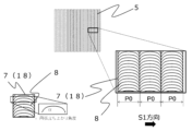
まず、図1に本発明におけるスリットタイプの光輝性動画模様(3)が透過性を有する基材(2)に貼付された印刷物(1)を示す。光輝性動画模様(3)は、少なくともホログラム形成層(12)と金属膜(13)を有する構成であり、反射光下において、動画的な視覚効果を生じる動画模様(4)が可視化されて視認される。好ましい形態として、動画模様(4)は、第一の動画模様(4-1)と第二の動画模様(4-2)を有する。なお、本第一の実施の形態において、動画模様(4)は、第一の動画模様(4-1)と第二の動画模様(4-2)により形成しているが、潜像要素群が金属膜を備えていない構成であれば、反射光下及び透過光下において異なる情報が確認できることから、潜像要素群が金属膜を備えない構成でのみ、本発明の光輝性動画模様(3)を形成してもよい。
(First embodiment)
First, FIG. 1 shows a printed matter (1) in which a slit-type glittering moving image pattern (3) of the present invention is attached to a transparent substrate (2). The glittering moving image pattern (3) has at least a hologram-forming layer (12) and a metal film (13), and a moving image pattern (4) that produces a moving image-like visual effect is visualized and visually recognized under reflected light. In a preferred embodiment, the moving image pattern (4) has a first moving image pattern (4-1) and a second moving image pattern (4-2). In this first embodiment, the moving image pattern (4) is formed by the first moving image pattern (4-1) and the second moving image pattern (4-2). However, if the latent image element group does not have a metal film, different information can be confirmed under reflected light and transmitted light. Therefore, the glittering moving image pattern (3) of the present invention may be formed only in a configuration in which the latent image element group does not have a metal film.
図2に光輝性動画模様(3)の構成の概要を示す。光輝性動画模様(3)は、光輝性要素群(5)と潜像要素群(6)とを備えて成る。潜像要素群(6)は、光輝性要素群(5)と干渉することで動画模様(4)を再生する画像の基となる。潜像要素群(6)は、第一の動画模様(4-1)を再生する働きを成す第一の潜像要素群(6-1)と、第二の動画模様(4-2)を再生する働きを成す第二の潜像要素群(6-2)に区分けされる。反射光下で真円として視認されていた動画模様(4)は、潜像要素群(6)と光輝性要素群(5)との干渉によって再生されたモアレ模様である。モアレ模様が発生する原理については、後述する。なお、本明細書において、光輝性要素群(5)は、樹脂によって形成された回折格子(18)を含むホログラム形成層(12)に蒸着を施した金属膜(13)を有する構造である。 Figure 2 shows an overview of the configuration of the glittering moving image pattern (3). The glittering moving image pattern (3) is composed of a glittering element group (5) and a latent image element group (6). The latent image element group (6) becomes the basis of an image that reproduces the moving image pattern (4) by interfering with the glittering element group (5). The latent image element group (6) is divided into a first latent image element group (6-1) that functions to reproduce the first moving image pattern (4-1) and a second latent image element group (6-2) that functions to reproduce the second moving image pattern (4-2). The moving image pattern (4) that was visually recognized as a perfect circle under reflected light is a moiré pattern reproduced by interference between the latent image element group (6) and the glittering element group (5). The principle of the generation of the moiré pattern will be described later. In this specification, the glittering element group (5) is a structure having a metal film (13) that is vapor-deposited onto a hologram-forming layer (12) that includes a diffraction grating (18) formed from a resin.
図3に光輝性要素群(5)の構成を示す。光輝性要素群(5)は、ライン状の光輝性要素(7)が第一の方向(S1方向)に特定の基準ピッチ(P0)で規則性を有して連続して配置されて成る。本明細書における「規則性を有して配置する」とは、複数の要素を同じ幅で同じピッチで同じ方向に連続して配置することを意味する。光輝性要素(7)の第一の方向(S1方向)の幅については、基準ピッチ(P0)以下の大きさであればいずれの大きさでも問題ない。ただし、本発明の効果が最も高いのは、ラインの幅が基準ピッチ(P0)と同じ値をとる場合である。図3の右下の拡大図に、光輝性要素(7)の内部の回折格子(18)を示す。第一の実施の形態における光輝性要素(7)は、連続した曲線による円弧状の格子線(8)が複数配列された回折格子(18)から成る。ただし、光輝性要素(7)内部の回折格子(18)の構成は、これに限定されるものではない。なお、本明細書において、回折格子(18)を形成する一つ一つの溝を格子線(8)と呼ぶ。 Figure 3 shows the configuration of the glittering element group (5). The glittering element group (5) is composed of linear glittering elements (7) arranged in a regular manner in a first direction (S1 direction) at a specific reference pitch (P0). In this specification, "arranged in a regular manner" means that multiple elements are arranged in a continuous manner in the same direction with the same width and pitch. The width of the glittering element (7) in the first direction (S1 direction) can be any size as long as it is less than the reference pitch (P0). However, the effect of the present invention is greatest when the line width is the same as the reference pitch (P0). The enlarged view at the bottom right of Figure 3 shows the diffraction grating (18) inside the glittering element (7). The glittering element (7) in the first embodiment is composed of a diffraction grating (18) in which multiple arc-shaped grating lines (8) are arranged by continuous curves. However, the configuration of the diffraction grating (18) inside the glittering element (7) is not limited to this. In this specification, each groove that forms the diffraction grating (18) is called a grating line (8).
第一の実施の形態における光輝性要素(7)内部の回折格子(18)の格子線(8)は、一部に格子線(8)の角度が連続的に変化する構造を有している形態を用いて説明する。格子線(8)は、直線でも曲線でも問題ないが、図3に示す円弧を用いる場合、円弧立ち上がり角度としては、スリットタイプであれば10度以上85度以下(逆側の端部であれば-10度以上-85度以下)とし、より望ましくは30度以上80度以下(逆側の端部であれば-30度以上-80度以下)である。この角度が小さすぎる場合、動画模様(4)の動きの大きさが小さくなり、大きすぎる場合は回折格子(18)の格子線(8)同士が重なりやすくなり、回折光が生じづらくなるため望ましくない。 The grating lines (8) of the diffraction grating (18) inside the luminous element (7) in the first embodiment are described using a form in which the angle of the grating lines (8) changes continuously in part. The grating lines (8) may be either straight or curved, but when the arc shown in FIG. 3 is used, the arc rise angle is 10 degrees or more and 85 degrees or less for a slit type (-10 degrees or more and -85 degrees or less for the opposite end), and more preferably 30 degrees or more and 80 degrees or less (-30 degrees or more and -80 degrees or less for the opposite end). If this angle is too small, the magnitude of movement of the animated pattern (4) becomes small, and if it is too large, the grating lines (8) of the diffraction grating (18) are likely to overlap with each other, making it difficult to generate diffracted light, which is undesirable.
例として、図4に光輝性要素(7)の回折格子(18)の構成の一例を示す。図4(a)の回折格子(18)は、光輝性要素(7)を縦方向に区分けした複数のセル(7a)ごとに、それぞれわずかに角度の異なる複数の直線の格子線(8)が配置されることで、疑似的に図3と同様な円弧状の回折格子(18)の構造を再現して成る。本例における格子線(8)の円弧立ち上がり角度に相当する角度は、約80度である。図4(b)の回折格子(18)は、光輝性要素(7)を横方向に区分けした複数のセル(7a)ごとに、それぞれわずかに角度の異なる複数の直線の格子線(8)が集中線状に配置されて成る。本例における格子線(8)の立ち上がり角度は、約-80度である。円弧状でない場合には、マイナスの角度であっても問題ない。 As an example, FIG. 4 shows an example of the configuration of the diffraction grating (18) of the glittering element (7). The diffraction grating (18) of FIG. 4(a) is formed by arranging a plurality of straight grating lines (8) with slightly different angles for each of a plurality of cells (7a) obtained by dividing the glittering element (7) vertically, thereby reproducing the structure of the arc-shaped diffraction grating (18) similar to that of FIG. 3. The angle corresponding to the arc rise angle of the grating lines (8) in this example is about 80 degrees. The diffraction grating (18) of FIG. 4(b) is formed by arranging a plurality of straight grating lines (8) with slightly different angles in a concentrated line shape for each of a plurality of cells (7a) obtained by dividing the glittering element (7) horizontally. The rise angle of the grating lines (8) in this example is about -80 degrees. If the grating lines are not arc-shaped, a negative angle is also acceptable.
図4(c)の回折格子(18)は、光輝性要素(7)を横方向に区分けした複数のセル(7a)ごとに、円弧又は曲線の格子線(8)の一部を切り出した構造であって、本例における格子線(8)の円弧立ち上がり角度は、約80度である。以上のように、光輝性要素(7)中の回折格子(18)は、少なくとも一部に格子線(8)の角度が一定の範囲で連続的に変化する構造を有していればよい。その角度変化の大きさは、30度以上180度以下とすることが望ましい。例えば、図4(a)の例でいえば、左端の円弧立ち上がり角度は、80度で中央が0度、右端の角度が-80度であれば、角度変化は160度である。この角度の変化が小さすぎる場合、入射光の角度変化によって、光輝性要素(8)中の光を反射する領域が連続的に移動する機能が低下し、動画模様(4)の動画効果が低くなり、逆に角度の変化が大きすぎる場合、動画模様(4)の視認性が低くなる。なお、図4は、光輝性要素(7)を複数のセル(7a)ごとに格子線(8)を集中線、円弧状に配置しているが、複数のセル(7a)に区分けせずに光輝性要素(7)ごとに格子線(8)を集中線、円弧状に配置してもよい。 The diffraction grating (18) in FIG. 4(c) has a structure in which a portion of the arc or curved lattice lines (8) is cut out for each of a plurality of cells (7a) obtained by dividing the glittering element (7) horizontally, and the arc rise angle of the lattice lines (8) in this example is about 80 degrees. As described above, the diffraction grating (18) in the glittering element (7) only needs to have a structure in which the angle of the lattice lines (8) changes continuously within a certain range in at least a portion. It is desirable that the magnitude of the angle change is 30 degrees or more and 180 degrees or less. For example, in the example of FIG. 4(a), if the arc rise angle at the left end is 80 degrees, the center is 0 degrees, and the angle at the right end is -80 degrees, the angle change is 160 degrees. If the change in angle is too small, the function of the light reflecting area in the glittering element (8) moving continuously due to the change in the angle of the incident light is reduced, and the animation effect of the animation pattern (4) is reduced, and conversely, if the change in angle is too large, the visibility of the animation pattern (4) is reduced. Note that in FIG. 4, the glittering elements (7) are arranged with the grid lines (8) in the form of converging lines or arcs for each of the multiple cells (7a), but the grid lines (8) may be arranged in the form of converging lines or arcs for each of the glittering elements (7) without dividing them into multiple cells (7a).
また、光輝性要素(7)について図2に示したように格子線(8)の配列角度が光輝性要素(7)内において徐々に変化する構造を用いて説明したが、本発明の光輝性要素(7)の格子線(8)の構造はこれに限定されず、格子線(8)の密度が変化する構造であってもよい。例えば、図19(a)に示すように、光輝性要素(7)中の格子線(8)の密度が粗から密、あるいは密から粗へと段階的に変化する構成を用いてもよい。図19に示すように、格子線(8)の密度が変化することでも、光輝性要素(8)中の光を反射する領域が連続的に移動する効果は生じる。格子線(8)の密度は200線/mmから5000線/mmの範囲で設計することが望ましく、より望ましくは範囲500線/mmから2000線/mmを含む範囲で設計することがより好ましい。 In addition, the glittering element (7) has been described using a structure in which the arrangement angle of the lattice lines (8) gradually changes within the glittering element (7) as shown in FIG. 2, but the structure of the lattice lines (8) of the glittering element (7) of the present invention is not limited to this, and the density of the lattice lines (8) may change. For example, as shown in FIG. 19(a), a structure in which the density of the lattice lines (8) in the glittering element (7) changes stepwise from sparse to dense, or from dense to sparse, may be used. As shown in FIG. 19, the change in density of the lattice lines (8) also produces the effect of the light-reflecting area in the glittering element (8) moving continuously. It is preferable to design the density of the lattice lines (8) in the range of 200 lines/mm to 5000 lines/mm, and more preferably in the range including 500 lines/mm to 2000 lines/mm.
また、図19(b)、図19(c)及び図19(d)に示すように、光輝性要素(7)内部が一定の幅の微小ライン単位(7a)で分割され、その微小ライン内部の格子線(8)の密度は同じであるものの、それぞれの微小ライン間の格子線(8)の密度は異なり、光輝性要素(7)の中で第一の方向(S1方向)に隣り合った微小ラインの格子線(8)の密度が、粗から密、あるいは密から粗へと方向性をもって段階的に増加あるいは減少する構成でもよい。いずれにしても、光輝性要素(7)は、入射光の角度変化によって、光輝性要素(7)中の光を反射する領域が連続的に移動する効果を有していれば、格子線(8)の構成は如何なる構成であっても問題ない。 Also, as shown in Figures 19(b), 19(c) and 19(d), the inside of the glittering element (7) may be divided into minute line units (7a) of a certain width, and the density of the lattice lines (8) inside the minute lines may be the same, but the density of the lattice lines (8) between each minute line may be different, and the density of the lattice lines (8) of minute lines adjacent to each other in the first direction (S1 direction) in the glittering element (7) may increase or decrease stepwise in a direction from sparse to dense, or from dense to sparse. In any case, as long as the glittering element (7) has the effect of continuously moving the light-reflecting area in the glittering element (7) as the angle of the incident light changes, any configuration of the lattice lines (8) is acceptable.
図5に、前述の構造を有する光輝性要素(7)に対して、入射光の角度が変化した場合に生じる効果を説明する。図5(a)に示すように、左にある光源(11)から光輝性要素(7)に光が入射した場合、それぞれの光輝性要素(7)が光を強く反射する面(7a)は、光輝性要素(7)の左側となる。図5(b)に示すように、中央にある光源(11)から光輝性要素(7)に光が入射した場合、それぞれの光輝性要素(7)が光を強く反射する面(7a)は、光輝性要素(7)の中央となる。図5(c)に示すように、右にある光源(11)から光輝性要素(7)に光が入射した場合、それぞれの光輝性要素(7)が光を強く反射する面(7a)は、光輝性要素(7)の右側となる。 Figure 5 illustrates the effect that occurs when the angle of incident light changes for the glittering element (7) having the above-mentioned structure. As shown in Figure 5(a), when light is incident on the glittering element (7) from the light source (11) on the left, the surface (7a) of each glittering element (7) that strongly reflects light is on the left side of the glittering element (7). As shown in Figure 5(b), when light is incident on the glittering element (7) from the light source (11) in the center, the surface (7a) of each glittering element (7) that strongly reflects light is in the center of the glittering element (7). As shown in Figure 5(c), when light is incident on the glittering element (7) from the light source (11) on the right, the surface (7a) of each glittering element (7) that strongly reflects light is on the right side of the glittering element (7).
以上のように、光源(11)が、第一の方向(S1方向)に移動するに従い、光輝性要素(7)の中の光を強く反射する面(7a)も、同じく第一の方向(S1方向)に連続的に移動する。なお、光源(11)の移動方向と、光輝性要素(7)が光を強く反射する面(7a)の移動方向は同じである必要はなく、逆方向に動いても問題ない。すなわち、光輝性要素(7)中の回折格子(18)が、格子線(8)の角度あるいは密度が連続的に変化する構造を有することによって、入射光の角度変化によって、光輝性要素(7)中の光を反射する領域が連続的に移動する効果を生じる。逆に、任意の方向から光が入射した場合に、光輝性要素(7)全体が光を反射する構造では本発明の要件を満たさない。 As described above, as the light source (11) moves in the first direction (S1 direction), the surface (7a) in the luminous element (7) that strongly reflects light also moves continuously in the first direction (S1 direction). The direction of movement of the light source (11) and the direction of movement of the surface (7a) in the luminous element (7) that strongly reflects light do not need to be the same, and there is no problem if they move in opposite directions. In other words, the diffraction grating (18) in the luminous element (7) has a structure in which the angle or density of the lattice lines (8) changes continuously, which creates the effect that the light-reflecting area in the luminous element (7) moves continuously as the angle of the incident light changes. Conversely, a structure in which the entire luminous element (7) reflects light when light is incident from any direction does not satisfy the requirements of the present invention.
本発明の光輝性要素(7)が備える、入射光の角度変化によって、光輝性要素(7)中の光を反射する領域が連続的に移動する効果は、本発明の動画効果を得るために不可欠なものである。以上のように、本発明の光輝性動画模様(3)は、光輝性要素(7)の回折格子(18)の少なくとも一部に、格子線(8)の角度が一定の範囲で連続的に変化する構造を有していなければならない。 The effect of the glittering element (7) of the present invention, in which the light-reflecting areas in the glittering element (7) move continuously as the angle of the incident light changes, is essential to achieving the moving image effect of the present invention. As described above, the glittering moving image pattern (3) of the present invention must have a structure in which at least a portion of the diffraction grating (18) of the glittering element (7) has a structure in which the angle of the grating lines (8) changes continuously within a certain range.
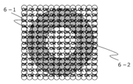
続いて、潜像要素群(6)について、図6を用いて説明する。潜像要素群(6)は、第一の潜像要素群(6-1)と第二の潜像要素群(6-2)に区分けされる。第一の潜像要素群(6-1)と第二の潜像要素群(6-2)の構成の違いは、金属膜(13)の有無であるが、それぞれの潜像要素群(6-1、6-2)の画線構成に工夫を設けることで、動画効果を多彩にすることができる。一例として、第一の潜像要素群(6-1)と第二の潜像要素群(6-2)の画線構成において、第一の動画模様(4-1)と第二の動画模様(4-2)が逆方向に移動する特殊な視覚効果を付与する構成を用いた例で説明する。 Next, the latent image element group (6) will be described with reference to FIG. 6. The latent image element group (6) is divided into a first latent image element group (6-1) and a second latent image element group (6-2). The difference between the configurations of the first latent image element group (6-1) and the second latent image element group (6-2) is the presence or absence of a metal film (13), but by incorporating ingenuity into the image configuration of each latent image element group (6-1, 6-2), a variety of moving image effects can be achieved. As an example, a configuration will be described in which a special visual effect is imparted in which the first moving image pattern (4-1) and the second moving image pattern (4-2) move in opposite directions in the image configuration of the first latent image element group (6-1) and the second latent image element group (6-2).
まず、第一の潜像要素群(6-1)の画線構成について説明する。まず、動画模様(4)として再生したい画像の基となる画像、本明細書中では、これを基画像(9)とし、第一の実施の形態では、出現させる画像を真円とする。この基画像(9)を光輝性要素(7)の配置方向である第一の方向(S1方向)に圧縮し、第一の潜像要素(10-1)とする。第一の潜像要素(10-1)の圧縮の度合いは、少なくとも配置するピッチ(P1、P2)よりも狭い幅に設定する必要がある。この第一の潜像要素(10-1)を光輝性要素(7)の配置方向と同じ第一の方向(S1方向)に特定の第一のピッチ(P1)で規則性を有して複数配列する。第一のピッチ(P1)及び第二のピッチ(P2)の値は、基準となる光輝性要素(7)の配置ピッチである基準ピッチ(P0)を100とすると、80%から120%の範囲の中の100%を除く数値に設定する必要がある。本例において、第一のピッチ(P1)は、基準ピッチ(P0)よりわずかに大きい値とした。 First, the image line configuration of the first latent image element group (6-1) will be described. First, the image that is the basis of the image to be reproduced as the moving image pattern (4) is referred to as the base image (9) in this specification, and in the first embodiment, the image to be made to appear is a perfect circle. This base image (9) is compressed in the first direction (S1 direction), which is the arrangement direction of the glittering elements (7), to form the first latent image element (10-1). The degree of compression of the first latent image element (10-1) needs to be set to a width narrower than the arrangement pitch (P1, P2). A plurality of these first latent image elements (10-1) are arranged with regularity at a specific first pitch (P1) in the first direction (S1 direction), which is the same as the arrangement direction of the glittering elements (7). The values of the first pitch (P1) and the second pitch (P2) must be set to values in the range of 80% to 120%, excluding 100%, assuming that the reference pitch (P0), which is the arrangement pitch of the reference lustrous elements (7), is 100. In this example, the first pitch (P1) is set to a value slightly larger than the reference pitch (P0).
続いて、対となる第二の潜像要素群(6-2)の画線構成について説明する。第二の潜像要素群(6-2)は、第二の潜像要素(10-2)を光輝性要素(7)の配置方向と同じ第一の方向(S1方向)に特定の第二のピッチ(P2)で規則性を有して複数配列する。仮に第一の潜像要素群(6-1)の第一のピッチ(P1)が基準ピッチ(P0)よりも大きな値に設定したとすると、第二のピッチ(P2)は、基準ピッチ(P0)よりも小さな値に設定することが望ましい。これは、光を反射させた場合に再生され、動画効果が生じる第一の動画模様(4-1)と第二の動画模様(4-2)の動きの方向を逆方向とするための工夫である。 Next, the image configuration of the paired second latent image element group (6-2) will be described. The second latent image element group (6-2) arranges a plurality of second latent image elements (10-2) with regularity at a specific second pitch (P2) in a first direction (S1 direction) that is the same as the arrangement direction of the glittering elements (7). If the first pitch (P1) of the first latent image element group (6-1) is set to a value larger than the reference pitch (P0), it is desirable to set the second pitch (P2) to a value smaller than the reference pitch (P0). This is a device for reversing the directions of movement of the first moving image pattern (4-1) and the second moving image pattern (4-2), which are reproduced when light is reflected and create a moving image effect.
また、今回、動画模様(4)としたのは真円であり、シンメトリーな画像であるが、仮に非シンメトリーな画像を用いて、第一のピッチ(P1)や第二のピッチ(P2)の値を基準ピッチ(P0)よりも大きな値とする場合には、基画像(9)を圧縮する際に、第一の方向(S1方向)と直角な方向を軸に基画像(9)をミラー反転させる必要がある。これは、第二の潜像要素(10-2)の配置ピッチ(P2)が基準ピッチ(P0)よりも大きい値の場合、再生される動画模様(4)は、基画像(9)をミラー反転させた画像となるためであり、これを防ぐためにはあらかじめ基画像(9)をミラー反転させておく必要がある。 In addition, the moving image pattern (4) used this time is a perfect circle, and is a symmetrical image, but if an asymmetrical image is used and the first pitch (P1) or second pitch (P2) is greater than the reference pitch (P0), then when compressing the base image (9), it is necessary to mirror-invert the base image (9) about an axis perpendicular to the first direction (S1 direction). This is because when the arrangement pitch (P2) of the second latent image elements (10-2) is greater than the reference pitch (P0), the reproduced moving image pattern (4) is an image obtained by mirror-inverting the base image (9), and in order to prevent this, it is necessary to mirror-invert the base image (9) beforehand.
なお、本明細書において、第一の潜像要素(10-1)と第二の潜像要素(10-2)は、同一の基画像(9)により形成しているが、互いに異なる基画像(9)により形成してもよい。 In this specification, the first latent image element (10-1) and the second latent image element (10-2) are formed from the same base image (9), but they may be formed from different base images (9).
以上のような構成の光輝性要素群(5)と潜像要素群(6)を組み合わせることで、光輝性動画模様(3)が構成される。本発明でいう「光輝性要素群(5)と潜像要素群(6)を組み合わせる」とは、図16(a)に示すように、潜像要素群(6)と光輝性要素群(5)が重なり合って、潜像要素(10)と光輝性要素(7)が重なった領域には光輝性要素(7)由来の回折格子(18)が存在しない形態を指す。また、「光輝性要素群(5)と潜像要素群(6)が一体化する」とは、図16(b)に示すように、潜像要素(10)の内部や輪郭が、本来、重なり合う光輝性要素(7)の回折格子(18)によって構成され、回折格子(18)を有する潜像要素(10)が存在するが、その周囲には光輝性要素(7)の回折格子(18)は存在しない形態を指す。 The glittering element group (5) and the latent image element group (6) configured as above are combined to form the glittering moving image pattern (3). In the present invention, "combining the glittering element group (5) and the latent image element group (6)" refers to a form in which the latent image element group (6) and the glittering element group (5) overlap, as shown in FIG. 16(a), and the diffraction grating (18) derived from the glittering element (7) does not exist in the area where the latent image element (10) and the glittering element (7) overlap. In addition, "integrating the glittering element group (5) and the latent image element group (6)" refers to a form in which the interior and outline of the latent image element (10) are originally formed by the diffraction grating (18) of the overlapping glittering element (7), as shown in FIG. 16(b), and there is a latent image element (10) with a diffraction grating (18), but the diffraction grating (18) of the glittering element (7) does not exist around it.
次に、図7に光輝性要素群(5)と、二つの潜像要素群(6)の断面構成について示す。光輝性要素(7)は、少なくとも回折格子(18)と金属膜(13)を有する。第一の潜像要素群(6-1)は、少なくとも金属膜(13)を有するが、格子線(8)が刻まれておらず、回折格子(18)を有さない(金属膜(13)により、第一の潜像要素群(6-1)を形成)。一方、第二の潜像要素群(6-2)は、少なくとも金属膜(13)を有さず、回折格子(18)を有しても有さなくともよい。本第一の実施の形態では、回折格子(18)を有さない形態とする。重要なのは、第一の潜像要素群(6-1)と第二の潜像要素群(6-2)の潜像要素群(6)に相当する領域のいずれか一方が金属膜(13)を有さず、もう一方は、金属膜(13)を有することである。 Next, FIG. 7 shows the cross-sectional structure of the glittering element group (5) and the two latent image element groups (6). The glittering element (7) has at least a diffraction grating (18) and a metal film (13). The first latent image element group (6-1) has at least a metal film (13), but the grating lines (8) are not engraved, and it does not have a diffraction grating (18) (the metal film (13) forms the first latent image element group (6-1)). On the other hand, the second latent image element group (6-2) does not have at least a metal film (13), and may or may not have a diffraction grating (18). In this first embodiment, it is a form that does not have a diffraction grating (18). What is important is that either one of the areas corresponding to the latent image element group (6) of the first latent image element group (6-1) or the second latent image element group (6-2) does not have a metal film (13), and the other has a metal film (13).
第二の潜像要素群(6-2)は、金属膜(13)を除去するか、そもそも蒸着を施さない構成である。金属膜を除去する場合には、金属膜の吸収波長帯にあたる波長のレーザを照射するか、酸又はアルカリ等の薬品により金属膜(13)を部分的に除去する方法で形成できる(ディメタライズ加工)。また、第二の潜像要素群(6-2)が回折格子(18)を有する場合は、第二の潜像要素群(6-2)の中に光輝性要素(7)と同じパターンの格子線(8)が刻まれている回折格子(15)の構成を用いてもよい。本実施の形態では、第一の潜像要素群(6-1)が金属膜(13)を有し、第二の潜像要素群(6-2)が金属膜(13)を有さない構成としたが、これが逆であってもよい。なお、本第一の実施形態は、第一の潜像要素群(6-1)と第二の潜像要素群(6-2)を上下に区分けして配置しているが、上下方向ではなく左右に区分けして配置してもよい。 The second latent image element group (6-2) is configured to either remove the metal film (13) or not be subjected to deposition in the first place. When removing the metal film, it can be formed by irradiating a laser having a wavelength corresponding to the absorption wavelength band of the metal film, or by partially removing the metal film (13) using a chemical such as an acid or alkali (demetallization process). In addition, when the second latent image element group (6-2) has a diffraction grating (18), a configuration of a diffraction grating (15) in which grating lines (8) of the same pattern as the glittering element (7) are engraved in the second latent image element group (6-2) may be used. In this embodiment, the first latent image element group (6-1) has a metal film (13), and the second latent image element group (6-2) does not have a metal film (13), but this may be reversed. In this first embodiment, the first latent image element group (6-1) and the second latent image element group (6-2) are arranged vertically, but they may be arranged horizontally instead of vertically.
本発明の反射光下における効果について説明する。まず、光輝性動画模様(3)に光を入射させ、反射光下で回折光が生じる状況で視認される効果を図8に示す。図8(a)に示すように、ある方向に存在する光源(11)から光が入射した場合、光輝性動画模様(3)の中に二つの動画模様(4-1、4-2)が出現する。続いて、図8(b)に示すように、光源(11)の位置が変化した場合、光輝性動画模様(3)の中に出現した二つの動画模様(4-1、4-2)のうち、一方は第一の方向(S1方向)に動き、もう一方は第一の方向(S1方向)と逆方向に動く。図8(c)に示すように、光源(11)の位置が変化した場合、光輝性動画模様(3)の中に出現した二つの動画模様(4-1、4-2)のうち、一方は第一の方向(S1方向)にさらに動き、もう一方は第一の方向(S1方向)と逆方向にさらに動く。以上のように、光源(11)と光輝性動画模様(3)との角度が変化することによって、光輝性動画模様(3)の中の二つの動画模様(4-1、4-2)にS1方向とS1方向の逆方向へと動く動画効果が生じる。また、この二つの動画模様(4-1、4-2)は、目視では同じ程度の濃度に見え、一見して違いを判別できないことは、本発明の特別な効果の一つである。 The effect of the present invention under reflected light will be explained. First, FIG. 8 shows the effect that is observed when light is incident on the glittering moving image pattern (3) and diffracted light is generated under reflected light. As shown in FIG. 8(a), when light is incident from a light source (11) located in a certain direction, two moving images (4-1, 4-2) appear in the glittering moving image pattern (3). Next, as shown in FIG. 8(b), when the position of the light source (11) is changed, one of the two moving images (4-1, 4-2) that appear in the glittering moving image pattern (3) moves in the first direction (S1 direction), and the other moves in the opposite direction to the first direction (S1 direction). As shown in FIG. 8(c), when the position of the light source (11) is changed, one of the two moving images (4-1, 4-2) that appear in the glittering moving image pattern (3) moves further in the first direction (S1 direction), and the other moves further in the opposite direction to the first direction (S1 direction). As described above, by changing the angle between the light source (11) and the glittering animation pattern (3), the two animation patterns (4-1, 4-2) in the glittering animation pattern (3) have an animation effect of moving in the S1 direction and the opposite direction to the S1 direction. In addition, the two animation patterns (4-1, 4-2) appear to have the same density to the naked eye, and the difference cannot be distinguished at a glance, which is one of the special effects of the present invention.
また、本発明の光輝性動画模様(3)のもう一つの特徴である、透過光下で透過模様が出現する効果について図9を用いて説明する。光輝性動画模様(3)を透過光下で観察すると、第一の潜像要素群(6-1)は光を遮断し、第二の潜像要素群(6-2)は光を透過する効果が生じる。本発明においては、光輝性要素群(5)も光を遮断する構成であるために、光輝性動画模様(3)を透かした場合には、第二の潜像要素群(6-2)のみに光を透過する効果が生じる。 Furthermore, the effect of a transparent pattern appearing under transmitted light, which is another feature of the glittering moving image pattern (3) of the present invention, will be explained using Figure 9. When the glittering moving image pattern (3) is observed under transmitted light, the first latent image element group (6-1) blocks light, and the second latent image element group (6-2) transmits light. In the present invention, since the glittering element group (5) is also configured to block light, when the glittering moving image pattern (3) is seen through, only the second latent image element group (6-2) transmits light.
以上のような効果が生じる原理について説明する。反射光下において、光輝性要素群(5)が光を反射した場合、回折格子由来の強い回折光によって極めて強い光が生じる一方、潜像要素群(6-1、6-2)は、回折光を発しないため、反射する光が相対的に極めて小さいものとなる。このため、光輝性動画模様(3)に光が入射した場合、光輝性要素群(5)と潜像要素群(6-1、6-2)によって強い光の明暗が生じる。なお、光輝性要素群(5)に光が入射した場合には、それぞれの潜像要素(10-1、10-2)が全面から一様に回折光を発するのではなく、図5に示したように内部の回折格子(18)の格子線(8)の角度が入射光と直交した部位のみが回折光を発する。 The principle of the above effect will be explained. When the glittering element group (5) reflects light under reflected light, an extremely strong light is generated due to the strong diffracted light from the diffraction grating, while the latent image element group (6-1, 6-2) does not emit diffracted light, so the reflected light is relatively very small. Therefore, when light is incident on the glittering moving image pattern (3), strong light and dark are generated by the glittering element group (5) and the latent image element group (6-1, 6-2). Note that when light is incident on the glittering element group (5), each latent image element (10-1, 10-2) does not emit diffracted light uniformly from the entire surface, but only the parts where the angle of the lattice lines (8) of the internal diffraction grating (18) perpendicular to the incident light emit diffracted light, as shown in FIG. 5.
この場合、光輝性要素群(5)からは、特定の基準ピッチ(P0)の周期で細い帯状に回折光が規則的に生じることとなる。この特定の基準ピッチ(P0)で帯状に生じた強い回折光によって、潜像要素群(6-1、6-2)が周期的にサンプリングされて可視化されることとなり、結果として二つの動画模様(4-1、4-2)が可視化される。全く異なる画像である潜像要素群(6)から動画模様(4)が再生されるのは、光輝性要素群(5)と潜像要素群(6)とが干渉することによって、Moire Magnification(以下、「モアレ拡大現象」という。)と呼ばれる特殊な現象が生じるためである。 In this case, thin bands of diffracted light are generated regularly from the glittering element group (5) at a specific reference pitch (P0). The strong bands of diffracted light generated at this specific reference pitch (P0) periodically sample and visualize the latent image element group (6-1, 6-2), resulting in the visualization of two video patterns (4-1, 4-2). The video pattern (4) is reproduced from the latent image element group (6), which is a completely different image, because the glittering element group (5) and the latent image element group (6) interfere with each other, causing a special phenomenon called Moire Magnification (hereinafter referred to as the "Moire Magnification Phenomenon").
層構造の異なる潜像要素群(6-1、6-2)が、反射光下では同じ程度の濃度に見え、異なる層構造であることを、一見して判別できない効果を得られるのは、光輝性要素群(6)の回折格子(18)と金属膜(13)の組み合わせに由来する強い回折光によって、動画模様(4-1、4-2)が再生されるためであり、金属膜(13)の有無のみの違いでは動画模様(4-1、4-2)の視認性に目視可能な影響を及ぼさない。一方、第二の潜像要素群(6-2)の構成として、回折格子(18)を有して、金属膜(13)を有さない形態も存在するが、この場合も、結果として二つの動画模様(4-1、4-2)は、目視上、同じ程度の濃度に視認され、異なる層構造を有することは一見して判別できない効果を得ることができる。 The latent image element groups (6-1, 6-2) with different layer structures appear to have the same density under reflected light, and the effect of being unable to distinguish at a glance that they have different layer structures is achieved because the moving image patterns (4-1, 4-2) are reproduced by strong diffracted light resulting from the combination of the diffraction grating (18) and metal film (13) of the glittering element group (6), and the difference only in the presence or absence of the metal film (13) does not have a visible effect on the visibility of the moving image patterns (4-1, 4-2). On the other hand, there is also a configuration of the second latent image element group (6-2) that has a diffraction grating (18) and does not have a metal film (13), but in this case as well, the two moving image patterns (4-1, 4-2) appear to have the same density to the naked eye, and the effect of being unable to distinguish at a glance that they have different layer structures can be achieved.
また、入射する光の角度が変化することで図5に示したように光輝性要素群(5)の中の強い回折光を発する領域が移動する。これによってサンプリングされる潜像要素群(6)の位置も変化し、結果として出現した動画模様(4-1、4-2)の位置が変化し、動画的な視覚効果が生じる。これが本発明において潜像要素群(6)とは全く異なる模様である動画模様(4)が再生され、かつ、入射する光の角度変化に応じて動画模様(4)が動いて見える効果が生じる原理である。 In addition, as the angle of the incident light changes, the area that emits strong diffracted light in the glittering element group (5) moves, as shown in Figure 5. This causes the position of the sampled latent image element group (6) to change, and as a result, the position of the appearing moving image pattern (4-1, 4-2) changes, creating a moving image visual effect. This is the principle by which the moving image pattern (4), which is a completely different pattern from the latent image element group (6), is reproduced in the present invention, and the moving image pattern (4) appears to move in response to changes in the angle of the incident light.
このモアレ拡大現象を用いることで様々な模様を拡大して、かつ動きを見せることが可能であり、この構成を適用することで、様々なバリエーションに富んだ動画効果を再現することができる。モアレ拡大現象の具体例については、後述する。 By using this moiré magnification phenomenon, it is possible to enlarge various patterns and make them appear to move, and by applying this configuration, a wide variety of moving image effects can be reproduced. Specific examples of the moiré magnification phenomenon will be described later.
続いて、透過光下で透過模様が生じる原理について説明する。光輝性要素群(5)と第一の潜像要素群(6-1)は、金属膜(13)が付与されているため、光は透過しない。一方で、第二の潜像要素群(6-2)は、金属膜(13)が付与されていないために光は透過する。したがって、金属膜(13)の有無によって透過光の強弱が生じることから、これによって図9に示したように、動画模様(4)とは異なる模様を透過模様として認証することによって真偽判別が可能となる。 Next, the principle of how a transparent pattern appears under transmitted light will be explained. The glittering element group (5) and the first latent image element group (6-1) are provided with a metal film (13), so light does not pass through them. On the other hand, the second latent image element group (6-2) is not provided with a metal film (13), so light passes through it. Therefore, the presence or absence of the metal film (13) creates variations in the intensity of the transmitted light, which makes it possible to determine whether the item is genuine or counterfeit by authenticating a pattern different from the animated pattern (4) as a transparent pattern, as shown in Figure 9.
以上のように、本発明の効果の特徴は、反射光下において、一見して違いが判別できない二つの動画模様(4-1、4-2)が、実際には異なる層構造を有しており、透過光下において、その層構造の違いに由来する透過模様を視認することができることにある。 As described above, the characteristic effect of the present invention is that the two animated patterns (4-1, 4-2), which are indistinguishable at first glance under reflected light, actually have different layer structures, and under transmitted light, a transmitted pattern resulting from the difference in the layer structures can be seen.
(第二の実施の形態)
続いて、第二の実施の形態として光輝性要素(7)が帯状のラインで形成されるのではなく、ドットで形成する構成について説明する。また、第一の実施の形態において、透過光下で認証できる透過模様は、潜像要素群(6-2)の画像がそのまま視認されるために特に意味を有さない模様であったが、第二の実施の形態の例においては、透過模様として意味のある有意情報を表す例について説明する。
Second Embodiment
Next, as a second embodiment, a configuration in which the glittering elements (7) are formed not in strip-like lines but in dots will be described. In the first embodiment, the transparent pattern that can be authenticated under transmitted light is a pattern that has no particular meaning because the image of the latent image element group (6-2) is directly visible, but in the example of the second embodiment, an example will be described in which the transparent pattern represents meaningful information.
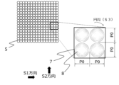
図10に、第二の実施の形態における光輝性要素群(5)を示す。ドット状の光輝性要素(7)内部の回折格子(18)は、同心円状の格子線(8)で構成されて成る。このドット状の光輝性要素(7)は、第一の方向(S1方向)に特定の基準ピッチ(P0)で、第二の方向(S2方向)に同じく特定の基準ピッチ(P0)で配置して成るが、第一の方向(S1方向)と第二の方向(S2方向)のピッチは同じである必要はなく、異なっていても良い。 Figure 10 shows a group of glittering elements (5) in the second embodiment. The diffraction grating (18) inside the dot-shaped glittering elements (7) is composed of concentric grating lines (8). The dot-shaped glittering elements (7) are arranged at a specific reference pitch (P0) in the first direction (S1 direction) and at the same specific reference pitch (P0) in the second direction (S2 direction), but the pitches in the first direction (S1 direction) and the second direction (S2 direction) do not need to be the same and may be different.
また、第二の実施の形態では、直径(P0)の真円でドットを構成しているが、真円である必要はなく、楕円や多角形等の形態を用いても問題ない。図18に示すように、回折格子(18)を構成する格子線(8)は同心円である必要はなく、格子線(8)を集中線や角度の異なる直線の集合等で構成しても問題なく、ラインの場合と同じく、効果として入射光の角度変化によって、光輝性要素(7)中の光を反射する領域が連続的に移動する効果を生じればよく、光輝性要素(7)の回折格子(18)の少なくとも一部に格子線(8)の角度が一定の範囲で連続的に変化する構造を有してればよい。 In the second embodiment, the dots are formed of perfect circles with a diameter (P0), but they do not need to be perfect circles, and it is also acceptable to use shapes such as ellipses and polygons. As shown in FIG. 18, the grating lines (8) that form the diffraction grating (18) do not need to be concentric circles, and it is also acceptable to form the grating lines (8) with converging lines or a collection of straight lines with different angles, and as with the case of lines, it is only necessary to have an effect that the light reflecting area in the glittering element (7) moves continuously as the angle of the incident light changes, and it is only necessary to have a structure in which at least a part of the diffraction grating (18) of the glittering element (7) has an angle of the grating lines (8) that changes continuously within a certain range.
続いて、図11にドット状の潜像要素群(6)の画線構成を示す。ドット状の潜像要素(10)は、反射時に再生したい基画像(9)を第一の方向(S1方向)及び第二の方向(S2方向)の両方向に圧縮した形態を有する。もともと微小な大きさの画像を基画像(9)として捉えても問題ない。本例では、アルファベットの「OK」を基画像(9)とし、これを縮小して潜像要素(10)とした。この潜像要素(10-1、10-2)を第一の方向(S1方向)に特定の第一のピッチ(P1)で、第二の方向(S2方向)に特定の第二のピッチ(P2)で連続して配置して成る。第一の方向(S1方向)に配置される特定の第一のピッチ(P1)は、同じであっても異なっていてもよい。この潜像要素(10)の第一のピッチ(P1)と第二のピッチ(P2)と光輝性要素(7)の基準ピッチ(P0)関係は、第一の実施の形態と同様であり、基準ピッチ(P0)を100とした場合、第一のピッチ(P1)及び第二のピッチ(P2)は、80%から120%の間の100%を除く値に設定する必要がある。 Next, FIG. 11 shows the image line configuration of the dot-shaped latent image element group (6). The dot-shaped latent image element (10) has a form in which the base image (9) to be reproduced upon reflection is compressed in both the first direction (S1 direction) and the second direction (S2 direction). There is no problem in regarding an image of a small size as the base image (9). In this example, the alphabet "OK" is used as the base image (9), which is then reduced to form the latent image element (10). These latent image elements (10-1, 10-2) are arranged in succession at a specific first pitch (P1) in the first direction (S1 direction) and at a specific second pitch (P2) in the second direction (S2 direction). The specific first pitch (P1) arranged in the first direction (S1 direction) may be the same or different. The relationship between the first pitch (P1) and second pitch (P2) of this latent image element (10) and the reference pitch (P0) of the glittering element (7) is the same as in the first embodiment, and when the reference pitch (P0) is set to 100, the first pitch (P1) and second pitch (P2) must be set to a value between 80% and 120%, excluding 100%.
図12に潜像要素群(6)の第一の潜像要素群(6-1)と第二の潜像要素群(6-2)との区分けを示す。説明の便宜上、第二の潜像要素群(6-2)と斜線で示しているが、実際には斜線は形成されていない。この斜線で示した円の丸の内部の「OK」が第二の潜像要素群(6-2)であり、その周囲を第一の潜像要素群(6-1)で区分けした構成とした。それぞれの構成は、第一の実施の形態と同じく、光輝性要素(7)は、少なくとも回折格子(18)に金属膜(13)を有する形態とする。第一の潜像要素群(6-1)は、少なくとも金属膜(13)を有し、回折格子(18)を有さない。第二の潜像要素群(6-2)は、少なくとも金属膜(13)を有さず、回折格子(18)を有しても有さなくともよい。本例では回折格子(18)を有さない形態とする。 Figure 12 shows the division of the latent image element group (6) into the first latent image element group (6-1) and the second latent image element group (6-2). For convenience of explanation, the second latent image element group (6-2) is shown with diagonal lines, but in reality, no diagonal lines are formed. The "OK" inside the circle shown with diagonal lines is the second latent image element group (6-2), and the surrounding area is divided by the first latent image element group (6-1). As with the first embodiment, each configuration is a form in which the glittering element (7) has at least a metal film (13) on the diffraction grating (18). The first latent image element group (6-1) has at least a metal film (13) and does not have a diffraction grating (18). The second latent image element group (6-2) does not have at least a metal film (13), and may or may not have a diffraction grating (18). In this example, a form without a diffraction grating (18) is used.
続いて、本発明の反射光下における効果について説明する。まず、光輝性動画模様(3)に光を入射させ、反射光下で回折光が生じる状況で視認される効果を図13に示す。図13(a)に示すように、ある方向にある光源(11)から光が入射した場合、光輝性動画模様(3)の中に二つの動画模様(4)が出現する。本第二の実施の形態において、出現する動画模様(4)は、二つで一対であり、光源が一つの場合二つの動画模様(4)が出現し、光源(11)が二つあれば、四つの動画模様(4)が出現する。 Next, the effect of the present invention under reflected light will be explained. First, Figure 13 shows the effect observed when light is incident on the glittering moving image pattern (3) and diffracted light is generated under reflected light. As shown in Figure 13 (a), when light is incident from a light source (11) in a certain direction, two moving image patterns (4) appear in the glittering moving image pattern (3). In this second embodiment, the moving image patterns (4) that appear are a pair of two, so when there is one light source, two moving image patterns (4) appear, and when there are two light sources (11), four moving image patterns (4) appear.
これは、第一の実施の形態の光輝性要素(7)と異なり、同心円のドットで構成した光輝性要素(7)は、一つの光源(11)から入射する光に対して直交する角度が二箇所存在するために、後述する図18に示すように、潜像要素群(6)をサンプリングする輝点(α1、α2)が二箇所となり、結果として二つの動画模様(4)が出現するためである。続いて、図13(b)に示すように、光源(11)の位置が変化した場合、光輝性動画模様(3)の中に出現した二つの動画模様(4)が、それぞれ逆方向に動きながら格子線(8)の円周(S3)に沿って回転する。図13(c)に示すように、光源(11)の位置が変化した場合、光輝性動画模様(3)の中に出現した二つの動画模様(4)は、さらに格子線(8)の円周(S3)に沿って回転して動く。以上のように、光源(11)の位置が変化することによって、光輝性動画模様(3)の中の二つの動画模様(4)が、格子線(8)の円周(S3)に沿って回転する動画効果が生じる。また、この二つの動画模様(4)の目視では、同じ程度の濃度に見え、一見して違いを判別できない。 This is because, unlike the glittering element (7) of the first embodiment, the glittering element (7) composed of concentric dots has two angles that are perpendicular to the light incident from one light source (11), so that, as shown in FIG. 18 described later, there are two bright points (α1, α2) that sample the latent image element group (6), resulting in the appearance of two animated patterns (4). Next, as shown in FIG. 13(b), when the position of the light source (11) is changed, the two animated patterns (4) that appeared in the glittering animated pattern (3) rotate along the circumference (S3) of the grid line (8) while moving in opposite directions. As shown in FIG. 13(c), when the position of the light source (11) is changed, the two animated patterns (4) that appeared in the glittering animated pattern (3) further rotate and move along the circumference (S3) of the grid line (8). As described above, by changing the position of the light source (11), a moving image effect is created in which the two moving image patterns (4) in the luminous moving image pattern (3) rotate along the circumference (S3) of the grid line (8). Furthermore, when viewed visually, the two moving image patterns (4) appear to have the same density, and the difference cannot be distinguished at first glance.
また、本発明の光輝性動画模様(3)のもう一つの特徴である、透過光下で透過模様が出現する効果について、図14を用いて説明する。光輝性動画模様(3)を透過光下で観察すると、第一の潜像要素群(6-1)は、光を遮断し、第二の潜像要素群(6-2)は、光を透過する効果が生じる。光輝性要素群(5)も光を遮断する構成であるために、光輝性動画模様(3)を透かした場合には、第二の潜像要素群(6-2)のみが光を透過し、結果として丸の図形が出現する。以上のように、第一の潜像要素群(6-1)と第二の潜像要素群(6-2)を任意に組み合わせることで、有意情報を構成し、潜像模様に意味を付与することができる。 Furthermore, the effect of the appearance of a transparent pattern under transmitted light, which is another feature of the glittering moving image pattern (3) of the present invention, will be explained using FIG. 14. When the glittering moving image pattern (3) is observed under transmitted light, the first latent image element group (6-1) blocks light, and the second latent image element group (6-2) transmits light. Since the glittering element group (5) is also configured to block light, when the glittering moving image pattern (3) is seen through, only the second latent image element group (6-2) transmits light, resulting in the appearance of a circular figure. As described above, by arbitrarily combining the first latent image element group (6-1) and the second latent image element group (6-2), significant information can be formed and meaning can be imparted to the latent image pattern.
なお、第一の実施の形態や第二の実施の形態において示した光輝性要素群(5)や潜像要素群(6)の図は、説明を明瞭にするためにデフォルメした画像であり、本来であれば、数百から数十μm単位の微小なラインやドットが大量に充填されて成り、ラインやドット自体は目視できない程度の大きさで極めて高い密度で構成される。このため、透過画像自体は、第二の実施の形態のように丸の図形のような単純な図柄に制限されるものではなく、第一の潜像要素群(6-1)と第二の潜像要素群(6-2)とに区分けすることで、複雑な文字や記号、マーク等を表すことができることは、いうまでもない。 The figures of the glittering element group (5) and the latent image element group (6) shown in the first and second embodiments are images that have been deformed to make the explanation clearer, and are essentially composed of a large number of tiny lines and dots measuring hundreds to tens of μm, with the lines and dots themselves being so small that they cannot be seen with the naked eye and composed at an extremely high density. Therefore, it goes without saying that the transmitted image itself is not limited to simple patterns such as circular shapes as in the second embodiment, and that by dividing it into a first latent image element group (6-1) and a second latent image element group (6-2), complex characters, symbols, marks, etc. can be expressed.
なお、反射光下で出現する動画模様(4)を二つではなく、一つにするには、同心円で構成される光輝性要素(7)を一般的な回折格子(18)ではなく、ブレーズド回折格子と呼ばれる断面方向に角度を有した特殊な構造の回折格子(18)を用いればよい。あるいは、特開2021-81705号公報に記載された特殊なドットの構成を用いればよい。この公報に記載のドットのように、360度の角度範囲の格子線(8)ではなく、180度以内の角度範囲の格子線(8)でドットを構成することで、一つの光源から入射する光に対して一つの動画模様(4)が出現する形態とすることができる。 In order to make one animated pattern (4) appear under reflected light instead of two, the luminous element (7) made up of concentric circles can be made up of a special structure called a blazed diffraction grating (18) that has an angle in the cross-sectional direction, rather than a general diffraction grating (18). Alternatively, the special dot configuration described in JP 2021-81705 A can be used. By configuring the dots with grid lines (8) in an angle range of 180 degrees or less, rather than grid lines (8) in an angle range of 360 degrees as in the dots described in this publication, it is possible to create a form in which one animated pattern (4) appears in response to light incident from one light source.
圧縮した文字や記号、図形等を、サンプリングの基となる光輝性動画模様(3)における光輝性要素(7)のピッチとわずかに異なるピッチで配置することで、圧縮した文字や記号等が拡大されて出現するモアレ拡大現象と呼ばれる現象は、特許第4844894号公報や特許第5131789号公報等で利用されているものであり、画線群や画素群に、わずかにピッチの異なる圧縮された画像を重ね合わせることで、圧縮された画像がモアレとして出現するものである。それぞれの実施の形態においてモアレ拡大現象の基画像(9)として丸や「OK」という単純な文字を選択したが、これに限定されるものではく、記号、数字、マーク、写真等の任意の画像を用いることができる。 The phenomenon known as moiré magnification, in which compressed letters, symbols, figures, etc. are arranged at a pitch slightly different from the pitch of the luminous elements (7) in the luminous moving image pattern (3) that is the basis for sampling, causing the compressed letters, symbols, etc. to appear enlarged, is used in Patent Publications No. 4844894 and No. 5131789, etc., in which a compressed image with a slightly different pitch is superimposed on a group of lines or a group of pixels, causing the compressed image to appear as a moiré. In each embodiment, a circle or a simple character such as "OK" is selected as the base image (9) for the moiré magnification phenomenon, but this is not limited to this and any image such as a symbol, number, mark, or photograph can be used.
また、ピッチを変化させる以外でモアレ拡大現象を利用する方法として、配置する文字や画像の配置角度をわずかに変える方法が存在する。例えば、現在垂直(90度)で構成されている文字(潜像要素(10))を、左右いずれかの方向にわずかに傾けた角度、第一の方向(S1)に連続して配置した場合でも、モアレ拡大現象が発現する。配置角度を大きく変えた場合には、出現するモアレに歪みが生じ、不明瞭になるため、配置角度を±5度程度に抑えることが望ましい。これら潜像要素(10)の角度の変化は、ピッチの変更と併用しても問題ない。潜像要素(10)の配置角度の変化を用いる場合には、ピッチが100%であっても問題ない。 In addition to changing the pitch, there is another method of utilizing the moire magnification phenomenon, which is to slightly change the angle at which characters or images are arranged. For example, the moire magnification phenomenon occurs even when characters (latent image elements (10)) that are currently configured vertically (90 degrees) are arranged continuously in a first direction (S1) at an angle slightly tilted to the left or right. If the angle is changed significantly, the moire that appears will be distorted and unclear, so it is desirable to keep the angle at about ±5 degrees. These changes in the angle of the latent image elements (10) can be used in conjunction with changes in the pitch without any problems. When using changes in the angle of the latent image elements (10), it is no problem if the pitch is 100%.
また、モアレ拡大現象のほかに、同様な圧縮画像を利用して動画効果を発現させ、かつ、潜像要素群(6)と動画模様(4)を異なる画像とすることができる画線構成として、立体画像の撮像方法から着想を得たIntegral Photography方式(以下、「IP画像方式」という。)と呼ばれる画線構成がある。これを潜像要素群(6)に適用することも可能であり、特許文献第5200284号に記載の潜像要素群(6)の構成を適用することで、より表現豊かな動画効果を発現させつつ、潜像要素群(6)の層構造を第一の潜像要素群(6-1)と第二の潜像要素群(6-2)に任意の形状に区分けすることで、本発明の透過光下で透過画像が認証できる形態としても良い。モアレ拡大現象やIP画像方式と呼ぶ画線構成を利用してホログラムを形成するには、特開2021-81705号公報に記載の構成と方法を本発明に用いればよい。 In addition to the moire magnification phenomenon, there is an image configuration called the Integral Photography method (hereinafter referred to as the "IP image method"), which is inspired by a method for capturing a stereoscopic image, that can create a moving image effect by using a similar compressed image and can make the latent image element group (6) and the moving image pattern (4) different images. This can also be applied to the latent image element group (6), and by applying the configuration of the latent image element group (6) described in Patent Document No. 5200284, a more expressive moving image effect can be created, and the layer structure of the latent image element group (6) can be divided into a first latent image element group (6-1) and a second latent image element group (6-2) in any shape, so that the transmitted image can be authenticated under the transmitted light of the present invention. To form a hologram using the moire magnification phenomenon or an image configuration called the IP image method, the configuration and method described in JP-A-2021-81705 can be used in the present invention.
一例として、図17に示すように、桜の花びらを基画像(9)に対して、第一の方向(S1方向)に一定の幅で基画像(9)を切り出し、特定の縮率で第一の方向(S1方向)に圧縮することで、一つの潜像要素(10)を作製する。基画像(9)を切り出す位置を同じピッチ(P1)、かつ、同一幅(W2)で第一の方向(S1方向)にずらしながら、切り出しから圧縮を繰り返して潜像要素(10)を順番に作製し、それぞれの潜像要素(10)を同じピッチ(P1)で第一の方向(S1方向)に並べることで潜像要素群(6)を作製することができる。 As an example, as shown in FIG. 17, cherry blossom petals are cut out of the base image (9) at a certain width in the first direction (S1 direction) and compressed in the first direction (S1 direction) at a specific reduction ratio to create one latent image element (10). The cut-out position of the base image (9) is shifted in the first direction (S1 direction) at the same pitch (P1) and the same width (W2), and the process from cutting out to compressing is repeated to create latent image elements (10) in sequence, and each latent image element (10) is arranged in the first direction (S1 direction) at the same pitch (P1) to create a group of latent image elements (6).
光輝性要素(7)中の回折格子(18)は、1mmあたり500本以上の格子線(8)の密度で構成することが望ましい。この場合、動画模様(4)は青、緑、黄、赤等の異なる色相に徐々に変化しながら動く効果を生じるためである。色相変化の効果を付与したい場合には、装置の描画能力に応じて500本から3000本程度の格子線(8)で構成すればよい。 The diffraction grating (18) in the luminous element (7) is preferably configured with a density of 500 or more grating lines (8) per mm. In this case, the moving image pattern (4) creates the effect of gradually changing to different hues such as blue, green, yellow, and red. If you want to create the effect of a hue change, you can configure it with about 500 to 3,000 grating lines (8) depending on the drawing capacity of the device.
図15に、本発明の光輝性動画模様(3)を用いた印刷物に貼付されることを想定した層構造の一例を示す。本明細書中では、本発明の光輝性動画模様(3)に関して、最低限の構成のホログラム形成層(12)と金属膜(13)や透明反射層(14)を施して輝度を高めたり、保護層(15)を設けて耐久性を高めたり、接着アンカー層(16)や接着層(17)を設けて基材に貼付できる形態とすることは、本発明の常識的な応用の範囲である。 Figure 15 shows an example of a layer structure that is intended to be attached to a printed matter using the photoluminescent moving image pattern (3) of the present invention. In this specification, it is within the scope of common sense applications of the present invention to provide the photoluminescent moving image pattern (3) of the present invention with a minimum configuration of a hologram forming layer (12), a metal film (13) or a transparent reflective layer (14) to increase brightness, a protective layer (15) to increase durability, or an adhesive anchor layer (16) or adhesive layer (17) to enable attachment to a substrate.
1 光輝性動画模様が貼付された印刷物
2 基材
3 光輝性動画模様
4 動画模様
4-1 第一の動画模様
4-2 第二の動画模様
5 光輝性要素群
6 潜像要素群
6-1 第一の潜像要素群
6-2 第二の潜像要素群
7 光輝性要素
8 回折格子の格子線
9 基画像
10 潜像要素
10-1 第一の潜像要素
10-2 第二の潜像要素
11 光源
12 ホログラム形成層
13 金属膜
14 透明反射層
15 保護層
16 接着アンカー層
17 接着層
18 回折格子
1 Printed matter with glittering moving image pattern attached 2
12
Claims (3)
前記光輝性要素群は、光輝性要素が規則性を有して複数配置されて成り、
前記光輝性要素は、複数の格子線が配置された回折格子と前記回折格子を覆う金属膜から成り、格子線への光の入射光の角度変化によって、光輝性要素における光を反射する領域が連続的に移動する構造を備え、
前記潜像要素群は回折格子を備えず、第一の潜像要素群と第二の潜像要素群に区分けされ、いずれか一方が前記金属膜を備えず、他方が前記金属膜を備えて成り、
更に、前記潜像要素群は、
1)基画像が圧縮された第一の潜像要素を、光輝性要素の配置方向又は配置ピッチの少なくともいずれか一方と異なる規則性を有して複数配置されて成る前記第一の潜像要素群と、前記基画像と同じ又は前記基画像と異なる基画像が圧縮された第二の潜像要素を、光輝性要素の配置方向又は配置ピッチの少なくともいずれか一方と異なる規則性を有して複数配置されて成る前記第二の潜像要素群から成り、又は、
2)基画像が分割圧縮された第一の潜像要素を、光輝性要素の配置方向又は配置ピッチの規則性と同じ規則性を有して複数配置されて成る前記第一の潜像要素群と、前記基画像と同じ又は前記基画像と異なる基画像が分割圧縮された第二の潜像要素を、光輝性要素の配置方向又は配置ピッチの規則性と同じ規則性を有して複数配置されて成る前記第二の潜像要素群から成り、
反射光下において、前記第一の潜像要素による第一の動画模様と前記第二の潜像要素による第二の動画模様が出現し、観察角度に応じて、前記第一の動画模様と前記第二の動画模様の位置が変化して視認され、
透過光下において、前記第一の潜像要素群と前記第二の潜像要素群のいずれか一方の前記金属膜を備えていない要素群の透過模様が視認されることを特徴とする光輝性動画模様形成体。 A glittering moving image pattern forming body having a glittering element group and a latent image element group,
The glittering element group is configured by arranging a plurality of glittering elements in a regular manner,
The glittering element is composed of a diffraction grating having a plurality of grating lines and a metal film covering the diffraction grating, and has a structure in which a light reflecting area in the glittering element moves continuously according to a change in an angle of the light incident on the grating lines;
the latent image element group does not include a diffraction grating and is divided into a first latent image element group and a second latent image element group, one of which does not include the metal film and the other includes the metal film;
Furthermore, the latent image element group is
1) The first latent image element group is composed of a plurality of first latent image elements obtained by compressing an original image, the plurality of first latent image elements being arranged with a regularity different from at least one of the arrangement direction or arrangement pitch of the glittering elements, and the second latent image element group is composed of a plurality of second latent image elements obtained by compressing an original image that is the same as the original image or different from the original image, the plurality of second latent image elements being arranged with a regularity different from at least one of the arrangement direction or arrangement pitch of the glittering elements, or
2) The first latent image element group is formed by dividing and compressing an original image, and the first latent image element group is formed by arranging a plurality of first latent image elements with the same regularity as the regularity of the arrangement direction or arrangement pitch of the glittering elements, and the second latent image element group is formed by arranging a plurality of second latent image elements with the same regularity as the regularity of the arrangement direction or arrangement pitch of the glittering elements, the second latent image element group being formed by dividing and compressing an original image that is the same as the original image or different from the original image,
a first moving image pattern formed by the first latent image element and a second moving image pattern formed by the second latent image element appear under reflected light, and positions of the first moving image pattern and the second moving image pattern are visually changed according to an observation angle;
A lustrous moving image pattern forming body, characterized in that under transmitted light, a transmitted pattern of either the first latent image element group or the second latent image element group that does not have the metal film is visible.
Priority Applications (1)
| Application Number | Priority Date | Filing Date | Title |
|---|---|---|---|
| JP2022008478A JP7691069B2 (en) | 2022-01-24 | 2022-01-24 | Photochromic moving image forming material |
Applications Claiming Priority (1)
| Application Number | Priority Date | Filing Date | Title |
|---|---|---|---|
| JP2022008478A JP7691069B2 (en) | 2022-01-24 | 2022-01-24 | Photochromic moving image forming material |
Publications (2)
| Publication Number | Publication Date |
|---|---|
| JP2023107332A JP2023107332A (en) | 2023-08-03 |
| JP7691069B2 true JP7691069B2 (en) | 2025-06-11 |
Family
ID=87474688
Family Applications (1)
| Application Number | Title | Priority Date | Filing Date |
|---|---|---|---|
| JP2022008478A Active JP7691069B2 (en) | 2022-01-24 | 2022-01-24 | Photochromic moving image forming material |
Country Status (1)
| Country | Link |
|---|---|
| JP (1) | JP7691069B2 (en) |
Families Citing this family (1)
| Publication number | Priority date | Publication date | Assignee | Title |
|---|---|---|---|---|
| JP2025006502A (en) | 2023-06-29 | 2025-01-17 | 日東シンコー株式会社 | Insulation sheet and motor |
Citations (6)
| Publication number | Priority date | Publication date | Assignee | Title |
|---|---|---|---|---|
| WO2009139396A1 (en) | 2008-05-01 | 2009-11-19 | 独立行政法人 国立印刷局 | Image forming material, and authenticity judgment device and authenticity judgment method |
| JP2011126028A (en) | 2009-12-15 | 2011-06-30 | National Printing Bureau | Latent image printed matter |
| JP2015171774A (en) | 2014-03-12 | 2015-10-01 | 独立行政法人 国立印刷局 | Stereoscopic molding and manufacture method thereof |
| WO2018043749A1 (en) | 2016-09-05 | 2018-03-08 | 凸版印刷株式会社 | Information display medium and manufacturing method relating thereto |
| JP2020093482A (en) | 2018-12-14 | 2020-06-18 | 独立行政法人 国立印刷局 | Latent image element forming layer, latent image forming body, and latent image forming medium provided with the latent image forming body |
| JP2021081705A (en) | 2019-11-18 | 2021-05-27 | 独立行政法人 国立印刷局 | Photoluminescent moving image pattern |
-
2022
- 2022-01-24 JP JP2022008478A patent/JP7691069B2/en active Active
Patent Citations (6)
| Publication number | Priority date | Publication date | Assignee | Title |
|---|---|---|---|---|
| WO2009139396A1 (en) | 2008-05-01 | 2009-11-19 | 独立行政法人 国立印刷局 | Image forming material, and authenticity judgment device and authenticity judgment method |
| JP2011126028A (en) | 2009-12-15 | 2011-06-30 | National Printing Bureau | Latent image printed matter |
| JP2015171774A (en) | 2014-03-12 | 2015-10-01 | 独立行政法人 国立印刷局 | Stereoscopic molding and manufacture method thereof |
| WO2018043749A1 (en) | 2016-09-05 | 2018-03-08 | 凸版印刷株式会社 | Information display medium and manufacturing method relating thereto |
| JP2020093482A (en) | 2018-12-14 | 2020-06-18 | 独立行政法人 国立印刷局 | Latent image element forming layer, latent image forming body, and latent image forming medium provided with the latent image forming body |
| JP2021081705A (en) | 2019-11-18 | 2021-05-27 | 独立行政法人 国立印刷局 | Photoluminescent moving image pattern |
Also Published As
| Publication number | Publication date |
|---|---|
| JP2023107332A (en) | 2023-08-03 |
Similar Documents
| Publication | Publication Date | Title |
|---|---|---|
| US10473831B2 (en) | Display having light-scattering property | |
| CN105636798B (en) | Safety device and manufacturing method | |
| CN111032365B (en) | Optically visible security element, production of such an element and security document provided with such an element | |
| JP5157115B2 (en) | Display comprising diffraction grating and printed matter using the same | |
| JP7240678B2 (en) | Glittering animated pattern | |
| TW202142905A (en) | Optical switch devices | |
| CN104249597B (en) | A kind of optical anti-counterfeit element | |
| JP2005525593A (en) | Optical variable element | |
| AU2016299396A1 (en) | Diffractive security device and method of manufacture thereof | |
| US10632779B2 (en) | Security device and method of manufacture thereof | |
| JP7691069B2 (en) | Photochromic moving image forming material | |
| JP2009168928A (en) | Display body and article with display body | |
| JP7153234B2 (en) | Optical modulator and information recording medium | |
| EP3793840B1 (en) | Security device and method of manufacture thereof | |
| CN110857003B (en) | Optical anti-counterfeiting element, design method thereof and anti-counterfeiting product | |
| JP2020093482A (en) | Latent image element forming layer, latent image forming body, and latent image forming medium provided with the latent image forming body | |
| JP7737648B2 (en) | Glittering pattern forming material | |
| JP7737645B2 (en) | Brilliant video pattern | |
| JP2023058001A (en) | Glittering animated pattern | |
| JP2024017854A (en) | Glitter animation pattern | |
| JP2023004693A (en) | Diffraction grating pattern | |
| JP2023107331A (en) | Glittering moving image pattern forming body and method for producing the same | |
| JP2017105042A (en) | Latent image printed matter |
Legal Events
| Date | Code | Title | Description |
|---|---|---|---|
| A621 | Written request for application examination |
Free format text: JAPANESE INTERMEDIATE CODE: A621 Effective date: 20240730 |
|
| A977 | Report on retrieval |
Free format text: JAPANESE INTERMEDIATE CODE: A971007 Effective date: 20250423 |
|
| TRDD | Decision of grant or rejection written | ||
| A01 | Written decision to grant a patent or to grant a registration (utility model) |
Free format text: JAPANESE INTERMEDIATE CODE: A01 Effective date: 20250520 |
|
| A61 | First payment of annual fees (during grant procedure) |
Free format text: JAPANESE INTERMEDIATE CODE: A61 Effective date: 20250521 |
|
| R150 | Certificate of patent or registration of utility model |
Ref document number: 7691069 Country of ref document: JP Free format text: JAPANESE INTERMEDIATE CODE: R150 |