JP7686828B1 - Concrete Finisher - Google Patents
Concrete Finisher Download PDFInfo
- Publication number
- JP7686828B1 JP7686828B1 JP2024052036A JP2024052036A JP7686828B1 JP 7686828 B1 JP7686828 B1 JP 7686828B1 JP 2024052036 A JP2024052036 A JP 2024052036A JP 2024052036 A JP2024052036 A JP 2024052036A JP 7686828 B1 JP7686828 B1 JP 7686828B1
- Authority
- JP
- Japan
- Prior art keywords
- concrete
- oscillating
- finishing member
- rail
- finisher
- Prior art date
- Legal status (The legal status is an assumption and is not a legal conclusion. Google has not performed a legal analysis and makes no representation as to the accuracy of the status listed.)
- Active
Links
Images


Landscapes
- On-Site Construction Work That Accompanies The Preparation And Application Of Concrete (AREA)
Abstract

【課題】小型で構造が簡単であり、大きな動力が不要でコンクリートを簡便に仕上げ施工できるコンクリートフィニッシャを提供する。
【解決手段】コンクリートフィニッシャ10は、コンクリート70の舗装幅方向の両側の枠部71に移動可能に配置された可動台20と、可動台20を接続するレール30と、レール30に移動可能に設けられコンクリート70を敷き均して仕上げる作業装置40と、作業装置40を移動させる移動機構34と、を備えている。作業装置40は、前後のフレーム48に上下方向に延出して回動可能に設けられた第1の軸51と、この第1の軸51に固定部材53を介して舗装方向前方に向けて揺動可能に設けられコンクリート70を敷き均して仕上げる第1の揺動仕上げ部材52と、この第1の揺動仕上げ部材52の揺動角度を制限する第1の揺動角度制限部材と、を備えている。
【選択図】図1
To provide a concrete finisher that is small in size, has a simple structure, does not require a large power source, and can easily finish concrete.
[Solution] The concrete finisher 10 comprises a movable platform 20 movably arranged on frame parts 71 on both sides in the paving width direction of concrete 70, rails 30 connecting the movable platform 20, a working device 40 movably mounted on the rails 30 for spreading and finishing the concrete 70, and a moving mechanism 34 for moving the working device 40. The working device 40 comprises a first shaft 51 extending in the vertical direction and rotatably mounted on front and rear frames 48, a first swinging finishing member 52 mounted on the first shaft 51 via a fixed member 53 for swinging forward in the paving direction for spreading and finishing the concrete 70, and a first swinging angle limiting member for limiting the swinging angle of the first swinging finishing member 52.
[Selected Figure] Figure 1
Description
本発明は、硬化前のコンクリートを敷き均して平坦に仕上げるコンクリートフィニッシャに関するものである。 The present invention relates to a concrete finisher that spreads and finishes pre-hardened concrete to a flat surface.
従来、コンクリート舗装では、硬化前のコンクリートを作業者が施工工具で敷き均して仕上げ、いわゆる左官ゴテでコンクリートを敷き均して仕上げたような状態にし、その後にコンクリートが硬化することでコンクリート舗装が形成されていた。このような、コンクリートを敷き均して仕上げる施工工具として特許文献1の工具が知られている。
Conventionally, concrete pavement is formed by workers spreading and finishing unhardened concrete with construction tools, in a state similar to that of spreading and finishing concrete with a plastering trowel, and then allowing the concrete to harden. The tool described in
特許文献1の施工工具は、作業者が手で握持可能な柄部材と、柄部材の先端部に柄部材と直角に交差した状態に取り付けられた支持部材と、支持部材に着脱可能に取り付けられた矩形板状の均し部材とを備えている。柄部材は固定部と、固定部に対しスライド可能に装着された伸縮部とを備えている。支持部材は横断面がC字状をした長尺の弾性材料で形成され、その内側には、均し部材の一方の長辺部を挟持可能な溝を有している。均し部材は弾性変形可能な発泡合成樹脂材で形成され、可撓性、伸縮性を有している。
The construction tool of
この施工工具を作業者が手で持って作業することで、固化前のコンクリートが平坦に敷き均され仕上げられる。 By holding this construction tool in their hands, workers can lay and finish the pre-hardened concrete evenly.
しかし、特許文献1の施工工具は、いわゆるレーキ状の工具であり、作業者が広い面積のコンクリート舗装を全て平坦に敷き均して仕上げるには、高度な技量と体力が求められるため、熟練作業者が減少している昨今では人手のみで施工することが困難である。そこで、コンクリートを平坦に敷き均して仕上げるコンクリートフィニッシャとよばれる機械装置も一般的に使用されている。
However, the construction tool in
従来からある一般的な機械装置のコンクリートフィニッシャとして、舗装幅方向に配置された作業台車上を作業機が左右に往復移動し、この作業機の端部に設置されたスクリューオーガにより作業台車前方に供給されたコンクリートを押し出し、バイブレータ付きプレートで平坦に敷き均して仕上げる装置が知られている。 A conventional concrete finisher is a common mechanical device that moves back and forth from side to side on a work platform placed across the width of the pavement. A screw auger attached to the end of the work platform pushes out concrete supplied to the front of the platform, and a vibrator-equipped plate finishes the concrete by spreading it flat and evenly.
しかし、従来からある一般的な機械装置のコンクリートフィニッシャは、装置が大型で構造が複雑であるうえに、コンクリートフィニッシャを移動させる走行装置も大きな動力が必要となる。 However, conventional concrete finishers are large and complex in structure, and the running gear that moves the concrete finisher requires a large amount of power.
本発明は、以上の点に鑑み、小型で構造が簡単であり、大きな動力が不要でコンクリートを簡便に仕上げ施工できるコンクリートフィニッシャを提供することを課題とする。 In view of the above, the present invention aims to provide a concrete finisher that is small, has a simple structure, does not require a large amount of power, and can easily finish and apply concrete.
本発明の実施例によれば、硬化前のコンクリートを敷き均して平坦に仕上げるコンクリートフィニッシャであって、
前記コンクリートの舗装幅方向の両側の枠部に移動可能に配置された可動台と、両側の前記可動台に掛け渡して設けられ前記可動台を接続するレールと、前記レールに移動可能に設けられ前記コンクリートを敷き均して仕上げる作業装置と、前記作業装置を前記レールに沿って移動させる移動機構と、を備え、
前記作業装置は、本体となるフレームと、前記フレームに上下方向に延出して設けられた第1の軸と、前記第1の軸に舗装方向前方に向けて揺動可能に設けられ前記コンクリートを敷き均して仕上げる第1の揺動仕上げ部材と、前記第1の揺動仕上げ部材の揺動角度を制限する第1の揺動角度制限部材と、を備えていることを特徴とする。
According to an embodiment of the present invention, there is provided a concrete finisher for spreading and finishing unhardened concrete to a flat surface, comprising:
The concrete pavement machine includes a movable platform movably arranged on both sides of the frame in the pavement width direction of the concrete, rails that are installed across the movable platforms on both sides and connect the movable platforms, a work device that is movably installed on the rails and spreads and finishes the concrete, and a movement mechanism that moves the work device along the rails,
The work device is characterized by comprising a frame serving as the main body, a first axis extending vertically from the frame, a first oscillating finishing member that is oscillatably mounted on the first axis toward the front in the paving direction and spreads and finishes the concrete, and a first swing angle limiting member that limits the swing angle of the first oscillating finishing member.
かかる構成によれば、コンクリートフィニッシャは、コンクリートの舗装幅方向の両側の枠部に移動可能に配置された可動台を接続するレールと、レールに移動機構を介して移動可能に設けられコンクリートを敷き均して仕上げる作業装置と、を備えている。作業装置は、フレームに上下方向に延出して設けられた第1の軸にコンクリートを敷き均して仕上げる第1の揺動仕上げ部材が舗装方向前方に向けて揺動可能に設けられているので、作業装置がレール上を左右(舗装幅方向)に往復移動するときに第1の揺動仕上げ部材によって、作業装置(可動台及びレール)前方に供給されたコンクリートを敷き広げることで、いわゆる左官ゴテでコンクリートを敷き均して仕上げるのと同様にコンクリートを仕上げることができる。また、第1の揺動仕上げ部材の揺動角度を制限する第1の揺動角度制限部材を備えているので、第1の揺動仕上げ部材がレールに沿って左右に移動する際に、移動直角方向から移動後方側へ揺動角度を保った状態で移動することで、コンクリートが仕上げ済みの舗装方向後方ではなく、未仕上げの舗装方向前方に押し出される。このため、作業装置を舗装幅方向に1回移動させる毎に、可動台及びレールを舗装方向前方に少し移動させて再び作業装置を舗装幅方向に1回移動させてコンクリートを仕上げる作業を繰り返すことで、コンクリート全面を綺麗に仕上げることができる。また、コンクリートフィニッシャは、2つの可動台及びレールと、移動機構により移動する小型の作業装置とからなるので、装置全体としても小型で構造が簡単であり、大きな動力が不要でコンクリートを簡便に仕上げ施工できる。 According to this configuration, the concrete finisher includes a rail that connects the movable platform that is movably arranged on both sides of the frame in the pavement width direction of the concrete, and a working device that is movably arranged on the rail via a moving mechanism and spreads and finishes the concrete. The working device is provided with a first oscillating finishing member that spreads and finishes the concrete on a first axis that is extended vertically from the frame and is oscillated toward the front in the paving direction, so that when the working device moves back and forth on the rail to the left and right (pavement width direction), the first oscillating finishing member spreads the concrete supplied to the front of the working device (movable platform and rail), thereby finishing the concrete in the same way as spreading and finishing the concrete with a so-called plastering trowel. In addition, since the first oscillating finishing member is provided with a first oscillating angle limiting member that limits the oscillating angle of the first oscillating finishing member, when the first oscillating finishing member moves left and right along the rail, it moves from the direction perpendicular to the movement to the rear side of the movement while maintaining the oscillating angle, so that the concrete is pushed forward in the unfinished pavement direction, not backward in the finished pavement direction. Therefore, every time the working device is moved once in the paving width direction, the movable platform and rail are moved slightly forward in the paving direction, and the working device is moved once again in the paving width direction to finish the concrete, and the entire surface of the concrete can be finished neatly. In addition, since the concrete finisher is made up of two movable platforms and rails, and a small working device that is moved by a moving mechanism, the entire device is small and has a simple structure, and does not require a large power source, making it easy to finish the concrete.
好ましくは、前記第1の揺動仕上げ部材の前記第1の軸と反対側の位置に上下方向に延出して設けられた第2の軸と、前記第2の軸に揺動可能に設けられ前記コンクリートを敷き均して仕上げる第2の揺動仕上げ部材と、前記第2の揺動仕上げ部材の揺動角度を制限する第2の揺動角度制限部材と、を備えている。 Preferably, the device includes a second shaft extending vertically from a position opposite the first shaft of the first oscillating finishing member, a second oscillating finishing member that is oscillatably mounted on the second shaft and spreads and finishes the concrete, and a second oscillating angle limiting member that limits the oscillating angle of the second oscillating finishing member.
かかる構成によれば、第1の揺動仕上げ部材の第1の軸と反対側の位置に上下方向に延出して設けられた第2の軸と、第2の軸に揺動可能に設けられコンクリートを敷き均して仕上げる第2の揺動仕上げ部材と、第2の揺動仕上げ部材の揺動角度を制限する第2の揺動角度制限部材と、を備えているので、第1の揺動仕上げ部材と併せて、揺動仕上げ部材が2段の角度で揺動する。仮に第1の揺動仕上げ部材のみで一定の範囲を仕上げる場合、揺動仕上げ部材の舗装方向後端のコンクリートが未仕上げの舗装方向前方に押し出されるまでの距離が長くなり第1の揺動仕上げ部材に大きな負荷が加わるところ、実施例のように第2の揺動仕上げ部材が第1の揺動仕上げ部材に対してさらに揺動することで、第2の揺動仕上げ部材の角度がさらに緩やかになってコンクリートを前方に受け流し易くなり、揺動仕上げ部材全体に加わる負荷を抑えることができる。これにより、移動機構を介して作業装置を小さな力で動かすことができる。 According to this configuration, the first oscillating finishing member includes a second shaft extending vertically at a position opposite to the first shaft, a second oscillating finishing member that is oscillatably mounted on the second shaft and that spreads and finishes the concrete, and a second oscillating angle limiting member that limits the oscillating angle of the second oscillating finishing member. Therefore, the oscillating finishing member oscillates at two angles together with the first oscillating finishing member. If a certain range is finished only with the first oscillating finishing member, the distance until the concrete at the rear end of the oscillating finishing member in the paving direction is pushed forward in the unfinished paving direction becomes long, and a large load is applied to the first oscillating finishing member. However, by further oscillating the second oscillating finishing member relative to the first oscillating finishing member as in the embodiment, the angle of the second oscillating finishing member becomes even gentler, making it easier to deflect the concrete forward, and the load applied to the entire oscillating finishing member can be reduced. This allows the working device to be moved with a small force via the moving mechanism.
好ましくは、前記揺動角度制限部材は、前記揺動仕上げ部材の揺動角度を左右それぞれに10度以上20度以下に制限し、
前記レールが平面視で舗装幅方向に対して斜めとなるレール角度で配置され、前記レール角度は前記揺動角度よりも小さい。
Preferably, the swing angle limiting member limits the swing angle of the swing finishing member to between 10 degrees and 20 degrees to the left and right,
The rails are arranged at a rail angle that is oblique to the pavement width direction in a plan view, and the rail angle is smaller than the swing angle.
かかる構成によれば、揺動仕上げ部材の揺動角度を10度未満にすると、コンクリートを舗装方向前方に流すために、レールの舗装幅方向に対する角度を大きくする必要があり、揺動部材の長さも大きくする必要が生じる。また、揺動仕上げ部材の揺動角度を20度より大きくすると1回の仕上げ幅が小さくなるため、これを回避するためやはり揺動部材の長さを大きくする必要がある。この点、揺動仕上げ部材の揺動角度を左右それぞれに10度以上20度以下に制限することで、揺動仕上げ部材の長さを小さくした状態で適度な仕上げ幅を確保し、作業効率を向上させることができる。また、レールが平面視で舗装幅方向に対して斜めとなるレール角度で配置され、レール角度は揺動角度よりも小さいので、作業装置がレール上を左右(舗装幅方向)に移動する度に、作業装置が到着していない左右いずれかの可動台を舗装方向前方に移動させて繰り返しコンクリートの仕上げ作業をすることができる。結果、コンクリートフィニッシャは、小型で構造が簡単であり、大きな動力が不要でコンクリートを簡便に仕上げ施工できる。 According to this configuration, if the swing angle of the swinging finishing member is less than 10 degrees, the angle of the rail with respect to the pavement width direction must be increased in order to flow the concrete forward in the pavement direction, and the length of the swinging member must also be increased. In addition, if the swing angle of the swinging finishing member is greater than 20 degrees, the finishing width per operation becomes smaller, so in order to avoid this, the length of the swinging member must also be increased. In this regard, by limiting the swinging angle of the swinging finishing member to 10 degrees or more and 20 degrees or less on each side, it is possible to ensure an appropriate finishing width while reducing the length of the swinging finishing member, thereby improving work efficiency. In addition, since the rail is arranged at a rail angle that is oblique to the pavement width direction in a plan view, and the rail angle is smaller than the swing angle, each time the working device moves left and right (pavement width direction) on the rail, the movable platform on either the left or right where the working device has not arrived can be moved forward in the pavement direction to repeatedly perform concrete finishing work. As a result, the concrete finisher is small and simple in structure, does not require a large power, and can easily finish concrete.
好ましくは、前記第1の揺動仕上げ部材は、棒状部材である。 Preferably, the first oscillating finishing member is a rod-shaped member.
かかる構成によれば、第1の揺動仕上げ部材は、棒状部材であるので、強度を保ちつつ、下部の円弧面で左右方向いずれもコンクリートを良好に敷き均して仕上げることができる。 With this configuration, the first oscillating finishing member is a rod-shaped member, so it can maintain its strength while allowing the lower arc surface to evenly spread and finish the concrete in both the left and right directions.
好ましくは、前記第2の揺動仕上げ部材は、ブレードである。 Preferably, the second oscillating finishing member is a blade.
かかる構成によれば、第2の揺動仕上げ部材は、ブレードであるので、小さなスペースで軽量にすることができる。 With this configuration, the second oscillating finishing member is a blade, so it can be made lightweight and occupy a small space.
好ましくは、前記移動機構は、前記レールの両端部にそれぞれ設けられたスプロケットと、前記スプロケットの間に掛けられたチェーンと、前記スプロケットを回転させるモータと、前記作業装置に設けられ前記チェーンに固定される固定部と、を備えている。 Preferably, the moving mechanism includes sprockets provided at both ends of the rail, a chain hung between the sprockets, a motor that rotates the sprockets, and a fixing part that is provided on the working device and fixed to the chain.
かかる構成によれば、移動機構はスプロケット、チェーン、モータ、及び固定部からなる簡単な構成であるので、コンクリートフィニッシャを、小型で簡単な構造にでき、大きな動力が不要でコンクリートを簡便に仕上げ施工することができる。さらに、可動台に対して、異なる長さのレールとチェーンに簡単に組み替えることができ、舗装幅の異なるコンクリートにも容易に対応することができる。 With this configuration, the moving mechanism is a simple structure consisting of a sprocket, a chain, a motor, and a fixed part, so the concrete finisher can be made small and simple in structure, and concrete can be easily finished without the need for a large power source. Furthermore, the movable platform can be easily assembled with rails and chains of different lengths, making it easy to handle concrete with different pavement widths.
小型で構造が簡単であり、大きな動力が不要でコンクリートを簡便に仕上げ施工できるコンクリートフィニッシャを提供することができる。 It is possible to provide a concrete finisher that is small, has a simple structure, does not require a large amount of power, and can easily finish and apply concrete.
本発明の実施の形態を添付図に基づいて以下に説明する。なお、図面は、コンクリートフィニッシャを概念的(模式的)に示すものとする。 The embodiment of the present invention will be described below with reference to the attached drawings. Note that the drawings are intended to conceptually (schematically) show a concrete finisher.
コンクリートフィニッシャ10を使用する周辺状況について説明する。
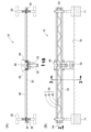
図1、図8に示されるように、例えば道路にコンクリート舗装を施工する場合、道路の舗装幅方向の両端に舗装方向に沿って枠部71が配置されている。なお、枠部71の代わりに角材、縁石、路肩を使用してもよい。道路の両端にある枠部71の上面は、敷き均して仕上げられるコンクリート70の上面より高い位置か同等の位置にあり、両側の枠部71に可動台20がそれぞれ配置され、両側の可動台20にレール30が掛け渡され接続されている。可動台20及びレール30は一体に移動させることができる。また、レール30にコンクリートを敷き均して仕上げる作業装置40が移動可能に設けられている。
The circumstances surrounding the use of the
As shown in Fig. 1 and Fig. 8, for example, when constructing a concrete pavement on a road,
次に、コンクリートフィニッシャ10について説明する。
図1に示されるように、コンクリートフィニッシャ10は、硬化前のコンクリート70を敷き均して平坦に仕上げる装置である。コンクリートフィニッシャ10は、コンクリート70の舗装幅方向の両側の枠部71に作業者の手によって移動可能に配置された可動台20と、両側の可動台20に掛け渡して設けられ可動台20を接続するレール30と、レール30に移動可能に設けられコンクリート70を敷き均して仕上げる作業装置40と、作業装置40をレール30に沿って移動させる移動機構34と、を備えている。
Next, the
As shown in Fig. 1, the
次に、可動台20について説明する。
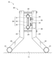
図1、図2に示されるように、可動台20は、枠部71に配置される2つの設置部21と、設置部21に側面視でハの字状に設けられたハの字部22と、ハの字部22の上部から上方に設けられた柱部23と、2つの柱部23を接続する上下の接続部24とからなる。また、舗装幅方向両側に配置される可動台20のうち、一方の可動台20には、移動機構を構成するモータ36が設けられ、このモータ36の軸にスプロケット34が設けられている。
Next, the
1 and 2, the
次に、レール30について説明する。
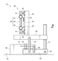
図1、図2、図4に示されるように、レール30は、可動台20の上部に設けられた上部レール31と、可動台20の上下方向中程に設けられた下部レール32と、上部レール31と下部レール32の間に斜めに設けられた複数の斜め補強部材33と、上部レール31及び下部レール32の幅方向両端部にそれぞれ回転可能に設けられたスプロケット34と、スプロケット34に掛けられたチェーン35と、1つのスプロケット34を駆動させるモータ36と、を備えている。なお、モータ36は、可動台20とレール30のいずれに設けられていてもよい。
Next, the
1, 2 and 4, the
次に、作業装置40について説明する。
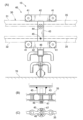
図1、図3~図7に示されるように、作業装置40は、レール30を転がり移動可能に設けられたローラー41と、これらのローラー41を回転可能に支持するローラー支持部42と、ローラー支持部42に設けられ本体となる上下のフレーム43と、この上下のフレーム43に回動可能に設けられ上側のチェーン35が掛けられた作業側スプロケット44と、上下のフレーム43に設けられ下側のチェーン35が固定れた固定部45と、上下のフレーム43の下端に前後方向(レール直角方向)に延びて設けられた前後のフレーム48と、を備えている。
Next, the working
As shown in Figures 1 and 3 to 7, the working
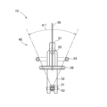
また、作業装置40は、前後のフレーム48に上下方向に延出して回動可能に設けられた第1の軸51と、この第1の軸51に固定部材53を介して舗装方向前方に向けて揺動可能に設けられコンクリート70を敷き均して仕上げる第1の揺動仕上げ部材52と、この第1の揺動仕上げ部材52の揺動角度を制限する第1の揺動角度制限部材54と、を備えている。
The working
また、作業装置40は、第1の揺動仕上げ部材52の第1の軸51と反対側の位置に上下方向に延出して設けられた第2の軸55と、この第2の軸55に揺動可能に固定部材57を介して設けられコンクリートを敷き均して仕上げる第2の揺動仕上げ部材56と、第2の揺動仕上げ部材56の揺動角度を制限する第2の揺動角度制限部材58と、を備えている。
The working
また、揺動角度制限部材54、58は、揺動仕上げ部材52、56の揺動角度を左右それぞれに15度に制限する(∠α1が示す第1の揺動仕上げ部材52は計30度揺動し、∠α2が示す第2の揺動仕上げ部材56も計30度揺動する)。レール30が平面視で舗装幅方向に対して斜めとなるレール角度で配置され(図8参照)、レール角度は揺動角度よりも小さくなるように設定されている。
The swing
また、第1の揺動仕上げ部材52は、棒状部材である。これにより、第1の揺動仕上げ部材52の強度を保ちつつ、下部の円弧面で左右方向いずれもコンクリート70を良好に敷き均して仕上げることができる。
The first
また、第2の揺動仕上げ部材56は、ブレードである。これにより、第2の揺動仕上げ部材56を、小さなスペースで軽量にすることができる。
The second
このように、第1の揺動仕上げ部材(棒状部材)52は、レール30に対して一定範囲内(左右に15度)で揺動可能となっており、第2の揺動仕上げ部材(ブレード)56も第1の揺動仕上げ部材(棒状部材)52に対して一定範囲内(左右に15度)で揺動可能となっている。
In this way, the first oscillating finishing member (rod-shaped member) 52 can oscillate within a certain range (15 degrees left and right) relative to the
なお、実施例では、揺動角度制限部材54、58を、揺動仕上げ部材52、56の揺動角度を左右それぞれに15度に制限するものとしたが、これに限定されず、揺動角度制限部材54、58を、揺動仕上げ部材52、56の揺動角度を左右それぞれに10度以上20度以下に制限するものとしてもよい。
In the embodiment, the swing
次に、移動機構について説明する。
移動機構は、レール30の両端部にそれぞれ設けられたスプロケット34、スプロケット34の間に掛けられたチェーン35と、スプロケット34を回転させるモータ36と、作業装置40に設けられチェーン35に固定される固定部45と、を備えている。なお、固定部45は、例えば、固定軸46を備え、この固定軸46をチェーン35の接続部に挿通して、固定部46の先端部をピン47で留める構成である。
Next, the movement mechanism will be described.
The movement mechanism includes
このように、実施例のコンクリートフィニッシャ10では、必要な動力は作業装置40がレール30上を横行する動力のみとなる。なお、固定部45の構成は上記の構成に限定されず、作業装置40をチェーン35に固定できれば他の構成であってもよい。
In this way, in the
次に、以上に述べた実施例のコンクリートフィニッシャ10の作用を説明する。
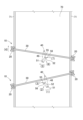
図8の下側に示されるように、硬化前のコンクリート70の舗装幅方向の両側に枠部71が配置されている。コンクリートフィニッシャ10は、左の可動台20を左の枠部71に配置し、右の可動台20を右の枠部71に配置している。右の可動台20は左の可動台20よりも舗装方向前方に配置しており、レール30の舗装幅方向に対する右上がりの角度は、例えば10度である。
Next, the operation of the
As shown in the lower part of Fig. 8,
この状態において、作業装置40をレール30の左端部に配置し、モータ(移動機構)36を作動させ、作業装置40を矢印(1)のように右方向に移動させる。すると、第1の揺動仕上げ部材52が矢印(2)のように揺動し、第2の揺動仕上げ部材56が矢印(3)のように揺動する。この状態で、作業装置40を矢印(1)のように右方向に移動させることで、コンクリート70が敷き均されて仕上げられるとともに余分なコンクリート70が舗装方向前方に押し出され、次の敷き均しにより仕上げられ、作業装置40がレール30の右端部に到達する。
In this state, the working
次に、図8の上側に示されるように、左の可動台20を矢印(4)のように舗装方向前方に移動させ、左の枠部71に配置する。レール30の舗装幅方向に対する左上がりの角度は、例えば10度になる。
Next, as shown in the upper part of Figure 8, the left
この状態において、レール30の右端部に配置されている作業装置40を、モータ(移動機構)36を作動させ、作業装置40を矢印(5)のように左方向に移動させる。すると、第1の揺動仕上げ部材52が矢印(6)のように揺動し、第2の揺動仕上げ部材56が矢印(7)のように揺動する。この状態で、作業装置40を矢印(5)のように左方向に移動させることで、コンクリート70が敷き均されて仕上げられるとともに余分なコンクリート70が舗装方向前方に押し出され、次の敷き均しにより仕上げられ、作業装置40がレール30の左端部に到達する。上記の作業を繰り返すことでコンクリート70全体が敷き均され仕上げられる。
In this state, the motor (movement mechanism) 36 of the working
このように、第1の揺動仕上げ部材(棒状部材)52と第2の揺動仕上げ部材(ブレード)56が、レール30上を左右に往復移動するときに、レール30前方に供給されたコンクリート70に押されながら敷き広げることで、いわゆる左官ゴテでコンクリート70を仕上げるのと同様にコンクリート70を仕上げることができる。
In this way, as the first oscillating finishing member (rod-shaped member) 52 and the second oscillating finishing member (blade) 56 move back and forth on the
次に、以上に述べた実施例のコンクリートフィニッシャ10の効果を説明する。
本発明の実施例では、コンクリートフィニッシャ10は、コンクリート70の舗装幅方向の両側の枠部71に移動可能に配置された可動台20を接続するレール30と、レール30に移動機構を介して移動可能に設けられコンクリート70を敷き均して仕上げる作業装置40と、を備えている。作業装置40は、フレーム43、48に上下方向に延出して設けられた第1の軸51にコンクリート70を敷き均して仕上げる第1の揺動仕上げ部材52が舗装方向前方に向けて揺動可能に設けられているので、作業装置40がレール30上を左右(舗装幅方向)に往復移動するときに第1の揺動仕上げ部材52によって、作業装置40(可動台20及びレール30)前方に供給されたコンクリート30を敷き広げることで、いわゆる左官ゴテでコンクリートを敷き均して仕上げるのと同様にコンクリート70を仕上げることができる。また、第1の揺動仕上げ部材52の揺動角度を制限する第1の揺動角度制限部材54を備えているので、第1の揺動仕上げ部材52がレール30に沿って左右に移動する際に、移動直角方向から移動後方側へ揺動角度を保った状態で移動することで、コンクリート30が仕上げ済みの舗装方向後方ではなく、未仕上げの舗装方向前方に押し出される。このため、作業装置40を舗装幅方向に1回移動させる毎に、可動台20及びレール30を舗装方向前方に少し移動させて再び作業装置40を舗装幅方向に1回移動させてコンクリート70を仕上げる作業を繰り返すことで、コンクリート70全面を綺麗に仕上げることができる。また、コンクリートフィニッシャ10は、2つの可動台20及びレール30と、移動機構により移動する小型の作業装置40とからなるので、装置全体としても小型で構造が簡単であり、大きな動力が不要でコンクリート70を簡便に仕上げ施工できる。
Next, the effects of the
In the embodiment of the present invention, the
さらに、第1の揺動仕上げ部材52の第1の軸51と反対側の位置に上下方向に延出して設けられた第2の軸55と、第2の軸55に揺動可能に設けられコンクリート70を敷き均して仕上げる第2の揺動仕上げ部材56と、第2の揺動仕上げ部材56の揺動角度を制限する第2の揺動角度制限部材58と、を備えているので、第1の揺動仕上げ部材52と併せて、揺動仕上げ部材52、56が2段の角度で揺動する。仮に第1の揺動仕上げ部材52のみで一定の範囲を仕上げる場合、揺動仕上げ部材52、56の舗装方向後端のコンクリート70が未仕上げの舗装方向前方に押し出されるまでの距離が長くなり第1の揺動仕上げ部材52に大きな負荷が加わるところ、実施例のように第2の揺動仕上げ部材56が第1の揺動仕上げ部材52に対してさらに揺動することで、第2の揺動仕上げ部材56の角度がさらに緩やかになってコンクリート70を前方に受け流し易くなり、揺動仕上げ部材全体に加わる負荷を抑えることができる。これにより、移動機構を介して作業装置40を小さな力で動かすことができる。
Furthermore, the first
さらに、揺動仕上げ部材52、56の揺動角度を10度未満にすると、コンクリート70を舗装方向前方に流すために、レール30の舗装幅方向に対する角度を大きくする必要があり、揺動部材52、56の長さも大きくする必要が生じる。また、揺動仕上げ部材52、56の揺動角度を20度より大きくすると1回の仕上げ幅が小さくなるため、これを回避するためやはり揺動部材仕上げ部材52、56の長さを大きくする必要がある。この点、揺動仕上げ部材52、56の揺動角度を左右それぞれに10度以上20度以下に制限することで、揺動仕上げ部材52、56の長さを小さくした状態で適度な仕上げ幅を確保し、作業効率を向上させることができる。また、レール30が平面視で舗装幅方向に対して斜めとなるレール角度で配置され、レール角度は揺動角度よりも小さいので、作業装置40がレール30上を左右(舗装幅方向)に移動する度に、作業装置40が到着していない左右いずれかの可動台20を舗装方向前方に移動させて繰り返しコンクリート70の仕上げ作業をすることができる。結果、コンクリートフィニッシャ10は、小型で構造が簡単であり、大きな動力が不要でコンクリート70を簡便に仕上げ施工できる。
Furthermore, if the swing angle of the
さらに、第1の揺動仕上げ部材52は、棒状部材であるので、強度を保ちつつ、下部の円弧面で左右方向いずれもコンクリート70を良好に敷き均して仕上げることができる。
Furthermore, because the first
さらに、第2の揺動仕上げ部材56は、ブレードであるので、小さなスペースで軽量にすることができる。
In addition, because the second
さらに、移動機構はスプロケット34、チェーン35、モータ36、及び固定部45からなる簡単な構成であるので、コンクリートフィニッシャ10を、小型で簡単な構造にでき、大きな動力が不要でコンクリート70を簡便に仕上げ施工することができる。さらに、可動台20に対して、異なる長さのレール30とチェーン35に簡単に組み替えることができ、舗装幅の異なるコンクリート70にも容易に対応することができる。
Furthermore, since the moving mechanism is a simple structure consisting of a
なお、実施例では、移動機構を、スプロケット34、チェーン35、モータ36、及び固定部45から構成され、外力により作業装置40が移動するものとしたが、これに限定されず、移動機構を作業装置40自体に設けた自走式の機構としてもよい。
In the embodiment, the moving mechanism is composed of a
また、実施例では、作業装置40は、第1の軸51を介して第1の揺動仕上げ部材52を設け、第2の軸55を介して第2の揺動仕上げ部材56を設け、2段階の揺動仕上げ部材52、56としたが、これに限定されず、1段階の揺動仕上げ部材、3段階の揺動仕上げ部材、4段階の揺動仕上げ部材、複数段の揺動仕上げ部材としてもよい。
In the embodiment, the working
即ち、本発明の作用及び効果を奏する限りにおいて、本発明は、実施例に限定されるものではない。 In other words, as long as the action and effect of the present invention are achieved, the present invention is not limited to the examples.
本発明の技術は、敷き均された硬化前のコンクリートを敷き均して平坦に仕上げるコンクリートフィニッシャに好適である。 The technology of the present invention is suitable for concrete finishers that spread and finish evenly the pre-hardened concrete.
10… コンクリートフィニッシャ
20… 可動台(作業台車)
30… レール(作業台車)
34… スプロケット(移動機構)
35… チェーン(移動機構)
36… モータ(移動機構)
40… 作業装置
43… 上下のフレーム(フレーム)
45… 固定部(移動機構)
48… 前後のフレーム(フレーム)
51… 第1の軸
52… 第1の揺動仕上げ部材(棒状部材)
54… 第1の角度制限部材
55… 第2の軸
56… 第2の揺動仕上げ部材(ブレード)
58… 第2の角度制限部材
70… コンクリート(硬化前のコンクリート)
71… 枠部(角材、縁石、路肩)
10...
30... Rail (work cart)
34... Sprocket (moving mechanism)
35... Chain (moving mechanism)
36... Motor (movement mechanism)
40: Working device 43: Upper and lower frames (frames)
45...Fixed part (moving mechanism)
48... Front and rear frames (frames)
51: First shaft 52: First oscillating finishing member (rod-shaped member)
54: First angle limiting member 55: Second shaft 56: Second oscillating finishing member (blade)
58: Second angle limiting member 70: Concrete (concrete before hardening)
71... Frame (timber, curbstone, road shoulder)
Claims (6)
前記コンクリートの舗装幅方向の両側の枠部に移動可能に配置された可動台と、両側の前記可動台に掛け渡して設けられ前記可動台を接続するレールと、前記レールに移動可能に設けられ前記コンクリートを敷き均して仕上げる作業装置と、前記作業装置を前記レールに沿って移動させる移動機構と、を備え、
前記作業装置は、本体となるフレームと、前記フレームに上下方向に延出して設けられた第1の軸と、前記第1の軸に舗装方向前方に向けて揺動可能に設けられ前記コンクリートを敷き均して仕上げる第1の揺動仕上げ部材と、前記第1の揺動仕上げ部材の揺動角度を制限する第1の揺動角度制限部材と、を備えていることを特徴とするコンクリートフィニッシャ。 A concrete finisher that spreads and finishes pre-hardened concrete to a flat surface,
The concrete pavement machine includes a movable platform movably arranged on both sides of the frame in the pavement width direction of the concrete, rails that are installed across the movable platforms on both sides and connect the movable platforms, a work device that is movably installed on the rails and spreads and finishes the concrete, and a movement mechanism that moves the work device along the rails,
The working device is a concrete finisher characterized in that it comprises a frame that serves as the main body, a first axis extending vertically from the frame, a first oscillating finishing member that is oscillatably mounted on the first axis toward the front in the paving direction and spreads and finishes the concrete, and a first swing angle limiting member that limits the swing angle of the first oscillating finishing member.
前記第1の揺動仕上げ部材の前記第1の軸と反対側の位置に上下方向に延出して設けられた第2の軸と、前記第2の軸に揺動可能に設けられ前記コンクリートを敷き均して仕上げる第2の揺動仕上げ部材と、前記第2の揺動仕上げ部材の揺動角度を制限する第2の揺動角度制限部材と、を備えていることを特徴とするコンクリートフィニッシャ。 2. The concrete finisher according to claim 1,
A concrete finisher characterized by comprising a second shaft extending in the vertical direction at a position opposite to the first shaft of the first oscillating finishing member, a second oscillating finishing member that is oscillatably mounted on the second shaft and spreads and finishes the concrete, and a second oscillating angle limiting member that limits the oscillating angle of the second oscillating finishing member.
前記揺動角度制限部材は、前記揺動仕上げ部材の揺動角度を左右それぞれに10度以上20度以下に制限し、
前記レールが平面視で舗装幅方向に対して斜めとなるレール角度で配置され、前記レール角度は前記揺動角度よりも小さいことを特徴とするコンクリートフィニッシャ。 The concrete finisher according to claim 1 or 2,
The swing angle limiting member limits the swing angle of the swing finishing member to between 10 degrees and 20 degrees to the left and right,
A concrete finisher characterized in that the rails are arranged at a rail angle that is oblique to the pavement width direction in a plan view, and the rail angle is smaller than the swing angle.
前記第1の揺動仕上げ部材は、棒状部材であることを特徴とするコンクリートフィニッシャ。 The concrete finisher according to claim 1 or 2,
A concrete finisher characterized in that the first oscillating finishing member is a rod-shaped member.
前記第2の揺動仕上げ部材は、ブレードであることを特徴とするコンクリートフィニッシャ。 3. The concrete finisher according to claim 2,
A concrete finisher characterized in that the second oscillating finishing member is a blade.
前記移動機構は、前記レールの両端部にそれぞれ設けられたスプロケットと、前記スプロケットの間に掛けられたチェーンと、前記スプロケットを回転させるモータと、前記作業装置に設けられ前記チェーンに固定される固定部と、を備えていることを特徴とするコンクリートフィニッシャ。
The concrete finisher according to claim 1 or 2,
The concrete finisher is characterized in that the moving mechanism includes sprockets provided at both ends of the rail, a chain hung between the sprockets, a motor for rotating the sprockets, and a fixed part provided on the working device and fixed to the chain.
Priority Applications (1)
| Application Number | Priority Date | Filing Date | Title |
|---|---|---|---|
| JP2024052036A JP7686828B1 (en) | 2024-03-27 | 2024-03-27 | Concrete Finisher |
Applications Claiming Priority (1)
| Application Number | Priority Date | Filing Date | Title |
|---|---|---|---|
| JP2024052036A JP7686828B1 (en) | 2024-03-27 | 2024-03-27 | Concrete Finisher |
Publications (2)
| Publication Number | Publication Date |
|---|---|
| JP7686828B1 true JP7686828B1 (en) | 2025-06-02 |
| JP2025150884A JP2025150884A (en) | 2025-10-09 |
Family
ID=95895093
Family Applications (1)
| Application Number | Title | Priority Date | Filing Date |
|---|---|---|---|
| JP2024052036A Active JP7686828B1 (en) | 2024-03-27 | 2024-03-27 | Concrete Finisher |
Country Status (1)
| Country | Link |
|---|---|
| JP (1) | JP7686828B1 (en) |
Citations (4)
| Publication number | Priority date | Publication date | Assignee | Title |
|---|---|---|---|---|
| JPH06287910A (en) * | 1992-05-19 | 1994-10-11 | Maeda Road Constr Co Ltd | Road paving apparatus |
| JPH08260417A (en) * | 1995-03-27 | 1996-10-08 | Nippon Hodo Co Ltd | Finishing screed |
| JPH08333710A (en) * | 1995-06-09 | 1996-12-17 | Nippon Hodo Co Ltd | Support structure for compaction equipment of concrete finisher |
| JP2023115602A (en) * | 2022-02-08 | 2023-08-21 | 株式会社Nippo | Concrete laying and leveling device and concrete laying and leveling method |
-
2024
- 2024-03-27 JP JP2024052036A patent/JP7686828B1/en active Active
Patent Citations (4)
| Publication number | Priority date | Publication date | Assignee | Title |
|---|---|---|---|---|
| JPH06287910A (en) * | 1992-05-19 | 1994-10-11 | Maeda Road Constr Co Ltd | Road paving apparatus |
| JPH08260417A (en) * | 1995-03-27 | 1996-10-08 | Nippon Hodo Co Ltd | Finishing screed |
| JPH08333710A (en) * | 1995-06-09 | 1996-12-17 | Nippon Hodo Co Ltd | Support structure for compaction equipment of concrete finisher |
| JP2023115602A (en) * | 2022-02-08 | 2023-08-21 | 株式会社Nippo | Concrete laying and leveling device and concrete laying and leveling method |
Also Published As
| Publication number | Publication date |
|---|---|
| JP2025150884A (en) | 2025-10-09 |
Similar Documents
| Publication | Publication Date | Title |
|---|---|---|
| CN100432355C (en) | Floor troweling device | |
| US3095789A (en) | Adjustable portable strike-off | |
| EP0756654B2 (en) | Machine for levelling concrete | |
| JP7686828B1 (en) | Concrete Finisher | |
| US5190396A (en) | Concrete leveling apparatus | |
| CN216034545U (en) | A steel pipe conveyer for construction | |
| CN110644748B (en) | a sanding machine | |
| CN202577910U (en) | Facing machine for building | |
| CN210190090U (en) | Prefabricated wallboard vibration screeding device | |
| ITTO960041A1 (en) | SELF-PROPELLED MACHINE FOR THE STABILIZATION, BY HAMMERING AND COMPACTION, OF TRACKS LAYED ON THE MASSAGE. | |
| US3256788A (en) | Concrete screeder | |
| KR20190001618U (en) | Apparatus for Ground Tamping | |
| KR101322639B1 (en) | Light weight concrete floor surface finshing device | |
| JP7680974B2 (en) | Concrete spreading device and concrete spreading method | |
| KR20210002301A (en) | Sludge-type mortar with a plaster finish on the screed vibration dapple bar | |
| JP5116648B2 (en) | Concrete distribution equipment | |
| CN211817772U (en) | Concrete trowelling machine capable of avoiding concrete cracking | |
| KR102729727B1 (en) | The flattening apparatus of costruction concrete | |
| CN217552641U (en) | T roof beam concrete flat sliding table that shakes | |
| KR100283524B1 (en) | Tunnel formwork conveying device | |
| JP2017145648A (en) | Invert concrete construction device | |
| US8366345B1 (en) | Powered screed machine | |
| CN206859011U (en) | Stent-type running gear | |
| CN214866842U (en) | A rapid bending device for steel bars for building construction | |
| CN220335652U (en) | Novel paving leveling machine |
Legal Events
| Date | Code | Title | Description |
|---|---|---|---|
| A621 | Written request for application examination |
Free format text: JAPANESE INTERMEDIATE CODE: A621 Effective date: 20250222 |
|
| A871 | Explanation of circumstances concerning accelerated examination |
Free format text: JAPANESE INTERMEDIATE CODE: A871 Effective date: 20250222 |
|
| TRDD | Decision of grant or rejection written | ||
| A01 | Written decision to grant a patent or to grant a registration (utility model) |
Free format text: JAPANESE INTERMEDIATE CODE: A01 Effective date: 20250422 |
|
| A61 | First payment of annual fees (during grant procedure) |
Free format text: JAPANESE INTERMEDIATE CODE: A61 Effective date: 20250521 |
|
| R150 | Certificate of patent or registration of utility model |
Ref document number: 7686828 Country of ref document: JP Free format text: JAPANESE INTERMEDIATE CODE: R150 |