JP7679727B2 - Printing device and method for controlling printing device - Google Patents
Printing device and method for controlling printing device Download PDFInfo
- Publication number
- JP7679727B2 JP7679727B2 JP2021133901A JP2021133901A JP7679727B2 JP 7679727 B2 JP7679727 B2 JP 7679727B2 JP 2021133901 A JP2021133901 A JP 2021133901A JP 2021133901 A JP2021133901 A JP 2021133901A JP 7679727 B2 JP7679727 B2 JP 7679727B2
- Authority
- JP
- Japan
- Prior art keywords
- unit
- printing
- image
- projection
- Prior art date
- Legal status (The legal status is an assumption and is not a legal conclusion. Google has not performed a legal analysis and makes no representation as to the accuracy of the status listed.)
- Active
Links
Images


Classifications
-
- G—PHYSICS
- G06—COMPUTING OR CALCULATING; COUNTING
- G06K—GRAPHICAL DATA READING; PRESENTATION OF DATA; RECORD CARRIERS; HANDLING RECORD CARRIERS
- G06K15/00—Arrangements for producing a permanent visual presentation of the output data, e.g. computer output printers
- G06K15/02—Arrangements for producing a permanent visual presentation of the output data, e.g. computer output printers using printers
- G06K15/025—Simulating output on another printing arrangement, e.g. proof output
-
- B—PERFORMING OPERATIONS; TRANSPORTING
- B41—PRINTING; LINING MACHINES; TYPEWRITERS; STAMPS
- B41J—TYPEWRITERS; SELECTIVE PRINTING MECHANISMS, i.e. MECHANISMS PRINTING OTHERWISE THAN FROM A FORME; CORRECTION OF TYPOGRAPHICAL ERRORS
- B41J29/00—Details of, or accessories for, typewriters or selective printing mechanisms not otherwise provided for
- B41J29/18—Mechanisms for rendering the print visible to the operator
- B41J29/19—Mechanisms for rendering the print visible to the operator with reflectors or illuminating devices
-
- B—PERFORMING OPERATIONS; TRANSPORTING
- B41—PRINTING; LINING MACHINES; TYPEWRITERS; STAMPS
- B41J—TYPEWRITERS; SELECTIVE PRINTING MECHANISMS, i.e. MECHANISMS PRINTING OTHERWISE THAN FROM A FORME; CORRECTION OF TYPOGRAPHICAL ERRORS
- B41J29/00—Details of, or accessories for, typewriters or selective printing mechanisms not otherwise provided for
- B41J29/38—Drives, motors, controls or automatic cut-off devices for the entire printing mechanism
- B41J29/393—Devices for controlling or analysing the entire machine ; Controlling or analysing mechanical parameters involving printing of test patterns
-
- G—PHYSICS
- G06—COMPUTING OR CALCULATING; COUNTING
- G06K—GRAPHICAL DATA READING; PRESENTATION OF DATA; RECORD CARRIERS; HANDLING RECORD CARRIERS
- G06K15/00—Arrangements for producing a permanent visual presentation of the output data, e.g. computer output printers
- G06K15/002—Interacting with the operator
- G06K15/005—Interacting with the operator only locally
-
- G—PHYSICS
- G06—COMPUTING OR CALCULATING; COUNTING
- G06K—GRAPHICAL DATA READING; PRESENTATION OF DATA; RECORD CARRIERS; HANDLING RECORD CARRIERS
- G06K15/00—Arrangements for producing a permanent visual presentation of the output data, e.g. computer output printers
- G06K15/02—Arrangements for producing a permanent visual presentation of the output data, e.g. computer output printers using printers
- G06K15/025—Simulating output on another printing arrangement, e.g. proof output
- G06K15/026—Simulating output on another printing arrangement, e.g. proof output introduction of proof output parameters
-
- B—PERFORMING OPERATIONS; TRANSPORTING
- B41—PRINTING; LINING MACHINES; TYPEWRITERS; STAMPS
- B41J—TYPEWRITERS; SELECTIVE PRINTING MECHANISMS, i.e. MECHANISMS PRINTING OTHERWISE THAN FROM A FORME; CORRECTION OF TYPOGRAPHICAL ERRORS
- B41J2203/00—Embodiments of or processes related to the control of the printing process
- B41J2203/01—Inspecting a printed medium or a medium to be printed using a sensing device
Landscapes
- Engineering & Computer Science (AREA)
- General Engineering & Computer Science (AREA)
- Physics & Mathematics (AREA)
- General Physics & Mathematics (AREA)
- Theoretical Computer Science (AREA)
- User Interface Of Digital Computer (AREA)
- Accessory Devices And Overall Control Thereof (AREA)
- Record Information Processing For Printing (AREA)
Description
本発明は、印刷装置、及び、印刷装置の制御方法に関する。 The present invention relates to a printing device and a method for controlling the printing device.
従来、特許文献1に示すように、印刷用治具に備えられた位置検出マークを検出して、印刷データを変更して印刷する装置が知られている。 Conventionally, as shown in Patent Document 1, a device is known that detects a position detection mark provided on a printing jig and changes the print data before printing.
しかしながら、特許文献1に記載の装置は、ユーザーが簡単に印刷データの印刷条件を変更することができなかった。 However, the device described in Patent Document 1 does not allow users to easily change the printing conditions of the print data.
印刷装置は、被印刷物に印刷をする印刷部と、前記被印刷物に印刷イメージを投影する投影部と、前記投影部が投影可能な投影エリア内のユーザーの動作を検出するための検出部と、印刷条件に基づき、前記印刷部を制御する制御部と、を備え、前記制御部は、前記検出部により検出した前記ユーザーの動作に基づき前記印刷条件を変更する。 The printing device includes a printing unit that prints on a substrate, a projection unit that projects a print image onto the substrate, a detection unit that detects the user's movements within a projection area that the projection unit can project onto, and a control unit that controls the printing unit based on printing conditions, and the control unit changes the printing conditions based on the user's movements detected by the detection unit.
印刷条件に基づき被印刷物に印刷をする印刷部と、前記被印刷物に印刷イメージを投影する投影部と、前記投影部が投影可能な投影エリア内のユーザーの動作を検出する検出部と、を備える印刷装置の制御方法であって、前記検出部により検出した前記ユーザーの動作に基づき、前記印刷条件を変更する。 A control method for a printing device that includes a printing unit that prints on a substrate based on printing conditions, a projection unit that projects a print image onto the substrate, and a detection unit that detects a user's actions within a projection area that the projection unit can project onto, and that changes the printing conditions based on the user's actions detected by the detection unit.
以下、実施形態について、図面を参照して説明する。なお、図中における方向を、三次元座標系を用いて説明する。説明の便宜上、Z軸の正方向を上方向又は単に上と称し負方向を下方向又は単に下と称し、Y軸の正方向を右方向又は単に右と称し負方向を左方向又は単に左と称し、X軸の負方向を前方向又は単に前と称し正方向を後方向又は単に後と称して説明する。 The following describes the embodiments with reference to the drawings. Directions in the drawings are described using a three-dimensional coordinate system. For ease of explanation, the positive direction of the Z axis is referred to as the upward direction or simply "up," the negative direction is referred to as the downward direction or simply "down," the positive direction of the Y axis is referred to as the rightward direction or simply "right," the negative direction is referred to as the leftward direction or simply "left," the negative direction of the X axis is referred to as the forward direction or simply "front," and the positive direction is referred to as the backward direction or simply "back."
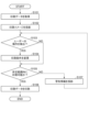
1.印刷装置の構成
図1に示すように、印刷装置1は、制御部10、記憶部11、印刷部12、主走査部13、副走査部14、プロジェクター20を含んで構成されている。プロジェクター20は、投影部21及び検出部22を有している。それぞれについて、図2も参照しながら具体的に説明していく。
1. Configuration of the Printing Device As shown in Fig. 1, the printing device 1 includes a
図1に示す制御部10は、印刷装置1の各部を統括的に制御するCPU(Central Processing Unit)、入出力を管理するUART(Universal Asynchronous Receiver Transmitter)、論理回路であるFPGA(Field Programmable Gate Array)やPLD(Programmable Logic Device)などを含んで構成されている。CPUは単にプロセッサーともいう。
記憶部11は、書き換え可能な不揮発性メモリーであるフラッシュROM(Read Only Memory)やHDD(Hard Disk Drive)、揮発性メモリーであるRAM(Random Access Memory)などを含んで構成されている。
制御部10のCPUは、記憶部11の不揮発性メモリーに記憶されたファームウェアなどのプログラムを読み出し、記憶部11のRAMを作業領域として用いて実行する。
1 includes a central processing unit (CPU) that controls each part of the printing device 1, a universal asynchronous receiver transmitter (UART) that manages input and output, and a field programmable gate array (FPGA) or programmable logic device (PLD) that is a logic circuit. The CPU is also simply called a processor.
The
The CPU of the
図2に示す被印刷物Pは、例として、普通紙、合成紙、フィルムなどのシート状のものでもよく、プラスチックなどの樹脂、鉄などの金属、木材などの立体形状のものでもよい。ユーザーは、被印刷物Pをテーブル30に載置する。
印刷部12は、インクジェット方式のヘッドを有している。例えば、印刷部12のヘッドから吐出されるインクは、いわゆる紫外線硬化型インクである。インクは、例えばCMYK(Cyan, Magenta, Yellow, Black)などの顔料を含んでいる。また、印刷部12は、ヘッドへインクを供給する供給機構も含んでいる。
図2に示すように、印刷装置1は、テーブル30に固定された被印刷物Pに対し、主走査部13及び副走査部14により、印刷部12を前後左右に走査して印刷をすることが可能である、いわゆるフラットベッドタイプの装置である。
2 may be, for example, a sheet-like object such as ordinary paper, synthetic paper, or film, or may be a three-dimensional object such as a resin such as plastic, a metal such as iron, or wood. The user places the object P on the table 30.
The
As shown in FIG. 2, the printing device 1 is a so-called flatbed type device that can print on a substrate P fixed to a table 30 by scanning the
主走査部13は、キャリッジ13a及びキャリッジ軸13bを含んで構成されている。
キャリッジ13aは、印刷部12を搭載している。キャリッジ軸13bは、テーブル30の前後方向に架け渡されている。キャリッジ軸13bは、キャリッジ13aを移動可能に支持している。
キャリッジ13aは、印刷部12を搭載し、キャリッジモーターにより、テーブル30に載せられた被印刷物Pの上を、キャリッジ軸13bに沿って前後方向に移動可能である。
The
The
The
副走査部14は、テーブル30の前後方向の端に、それぞれスライダー14b及びガイドレール14aを含んで構成されている。
ガイドレール14aは、テーブル30の左右方向に延びた溝により構成されている。スライダー14bは、一方の端をキャリッジ軸13bに固定され、他方の端をガイドレール14aの溝に移動可能に嵌合されている。スライダー14bは、スライダーモーターにより、ガイドレール14aに沿って、キャリッジ軸13bを左右方向に移動可能である。
The
The
制御部10は、主走査部13を制御して印刷部12を前後方向に移動することが可能であり、副走査部14を制御してキャリッジ軸13bを介して印刷部12を左右方向に移動することが可能である。主走査部13による走査方向及び副走査部14による走査方向は、互いに交差する方向である。
制御部10は、テーブル30に固定された被印刷物Pに対し、主走査部13及び副走査部14を制御し、印刷部12を前後左右に走査しながら、印刷部12からインクを吐出して印刷を行うことができる。
The
The
プロジェクター20は、例えば、投影部21及び検出部22を有する、いわゆるインタラクティブタイプのものである。プロジェクター20は支持部23によりテーブル30に支持されている。プロジェクター20の投影部21及び検出部22は、テーブル30の上に位置している。投影部21はテーブル30に向かって投影可能であり、検出部22はテーブル30に向かって検出可能である。
なお、投影部21及び検出部22がそれぞれ独立して構成されていてもよい。この場合、投影部21及び検出部22は、それぞれが個別にテーブル30に支持される。
The
The
投影部21は、光源の光を3原色成分である赤色光、青色光、緑色光に分離し、画像データに基づき、各色光用の液晶ライトバルブにより各色の光を変調し、再度合成し、レンズで拡大等して、テーブル30に向かって投影するように構成されている。
投影部21により被印刷物Pへ投影する画像データである後述の印刷イメージは、印刷条件に基づき印刷部12により被印刷物Pに印刷した印刷結果に対応するように、位置やサイズなどを調整されている。ユーザーは、被印刷物Pへ投影された印刷イメージを視認することにより、疑似的に、被印刷物Pに印刷した印刷結果として認識することができる。
The
The print image (described later), which is image data projected by the
投影部21がテーブル30に対し投影可能な投影エリアは、例えば、テーブル30のサイズであってもよい。又は、投影エリアは、テーブル30の前後左右のサイズに対して一回り小さい範囲であって、所定のマージンを確保した範囲であってもよい。
また、制御部10は、投影部21により、投影エリアの所定の位置へ、所定のメニューを示すアイコンなどを投影することもできる。
The projection area onto the table 30 that the
Furthermore, the
検出部22は、テーブル30からの反射光を受光する。検出部22は、例えば、CCD(Charge Coupled Device)イメージセンサなどの固体撮像素子を有するカメラで構成されている。また、検出部22は、照明装置を備えることが好ましい。
なお、ユーザーの指などの非発光の物体を検出する場合、検出部22は赤外光を用いることが好ましい。この場合、テーブル30に向かって赤外光を照射する照明装置を備えると共に、赤外光の帯域を中心に透過させるフィルターをカメラに装着することが好ましい。
検出部22は、投影部21により投影可能な投影エリアを、検出画像データとして検出することができる。以下では、検出画像データを単に検出画像と称する。
The
In addition, when detecting a non-luminous object such as a user's finger, it is preferable that the
The
印刷装置1は、外部装置2との間で有線通信又は無線通信が可能である。外部装置2は、例えば、コンピューター、サーバーなどである。印刷装置1は、外部装置2から印刷データ及び印刷条件を受信し、記憶部11に記憶することができる。
なお、印刷データ及び印刷条件は、予め記憶部11に記憶されていてもよく、記憶部11に設けられている読取装置により記憶媒体から読み取られるようにしてもよい。
また、投影部21によりメニューを示すアイコンを投影し、アイコンに対するユーザーの動作を検出部22により検出し、印刷条件の変更、印刷実行などの指示を受け付けることができる。
また、印刷装置1は、タッチパネルなどの入出力装置を備えていてもよい。印刷装置1のタッチパネルにより、メニューを表示し、印刷条件の変更、印刷実行などの指示を受け付けることができる。
The printing device 1 is capable of wired or wireless communication with an external device 2. The external device 2 is, for example, a computer or a server. The printing device 1 can receive print data and printing conditions from the external device 2 and store them in a
The print data and the print conditions may be stored in advance in the
In addition, the
The printing device 1 may also include an input/output device such as a touch panel. The touch panel of the printing device 1 can display menus and accept instructions such as changing printing conditions and executing printing.
2.印刷装置の制御方法
図3に示すフローチャートを中心に、図4及び図5も参照しながら、印刷装置1の制御方法の一例について説明する。
制御部10は、外部装置2から印刷データを取得するか、又は、記憶部11から印刷データを取得する(S101)。さらに、制御部10は、外部装置2から印刷条件を取得するか、又は、記憶部11から印刷条件を取得する。また、上述のように、ユーザーによる印刷条件の変更を、プロジェクター20の検出部22やタッチパネルなどにより検出してもよい。
制御部10は、取得した印刷データ及び印刷条件に基づき、投影部21により投影可能な画像データである印刷イメージを生成する。
制御部10は、プロジェクター20の投影部21により、被印刷物Pが置かれたテーブル30に向かって、生成した印刷イメージを投影する(S102)。
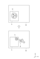
図4及び図5は、プロジェクター20の投影部21が、被印刷物Pが置かれたテーブル30に向かって、生成した印刷イメージである、印刷イメージI1、印刷イメージI2、印刷イメージI3、印刷イメージI4などを投影した結果を示している。
2. Printing Apparatus Control Method An example of a control method for the printing apparatus 1 will be described with reference to the flowchart shown in Fig. 3 and also to Figs.
The
The
The
Figures 4 and 5 show the results of the
ここで、制御部10が生成する印刷イメージ及び印刷データの関係について、図4の左の形態の印刷イメージI1を例に詳しく説明する。
制御部10が取得する印刷条件は、例えば、テーブル30に載置された被印刷物Pに対し印刷した場合の印刷データの位置や、印刷する際のサイズに係るものである。
記憶部11は、テーブル30の位置を基準としたX方向及びY方向の座標の情報を記憶している。座標は、記憶部11に印刷データを記憶する第1アドレスの記憶領域に対応している。また、この座標は、図4及び図5に示すように、テーブル30におけるX軸及びY軸に対応させることができる。
制御部10は、印刷条件により指定された位置及びサイズに基づき、座標に対応させて、記憶部11の第1アドレスに印刷データを記憶する。
なお、以下の説明では、記憶部11における、第1アドレスの記憶領域、後述の第2アドレスの記憶領域、第3アドレスの記憶領域を、それぞれ単に第1アドレス、第2アドレス、第3アドレスと称する。第2アドレス、第3アドレスも、第1アドレスと同様に、座標に対応している。
Here, the relationship between the print image and print data generated by the
The printing conditions acquired by the
The
The
In the following description, the first address storage area, the second address storage area, and the third address storage area in the
上述のように、印刷データが記憶されている記憶部11の第1アドレスは、テーブル30の座標の位置に対応している。
制御部10は、記憶部11から印刷データを読み出し、主走査部13及び副走査部14により、印刷データが記憶されている記憶部11の第1アドレスに対応するテーブル30の座標の位置へ印刷部12を走査し、インクを吐出することができる。
この結果、制御部10は、テーブル30に載置された被印刷物Pに対し、印刷条件に基づく位置及びサイズで、印刷部12により印刷データを印刷することができる。
As described above, the first address in the
The
As a result, the
制御部10は、印刷データ及び印刷条件に基づき、実際に被印刷物Pに対して印刷した印刷結果に対応するように、色変換等を行い、印刷イメージI1を生成する。
生成した印刷イメージI1は、記憶部11の第2アドレスに記憶される。上述のように、第2アドレスも、テーブル30の位置を基準とした座標に対応しており、印刷データを記憶する第1アドレスに対応している。
The
The generated print image I1 is stored in a second address of the
制御部10は、プロジェクター20の投影部21を制御し、記憶部11の第2アドレスから印刷イメージI1を読み出し、印刷イメージI1が記憶されている第2アドレスに対応するテーブル30の座標の位置へ向かって投影することができる。
このように、制御部10は、被印刷物Pが載置されたテーブル30に対し、印刷条件に基づく位置及びサイズなどを反映した印刷イメージI1を投影することができる。
この結果、制御部10が、プロジェクター20の投影部21によりテーブル30に向かって投影した印刷イメージI1は、位置及びサイズなどを含め、印刷部12により印刷した場合の印刷結果に対応している。
ユーザーは、被印刷物Pに印刷する前に、投影部21により投影された印刷イメージI1を視認することにより、目的とする印刷条件などで被印刷物Pに印刷データが印刷されるかを、確認することができる。
The
In this way, the
As a result, the print image I1 projected by the
Before printing on the substrate P, the user can visually check the print image I1 projected by the
このとき、例えば、ユーザーは、投影部21により投影された印刷イメージI1が、目的とする位置やサイズではなかったと判断したとする。
図4の左の形態に示すように、ユーザーは、テーブル30に投影された印刷イメージI1に対し、指を当てる「タップ」のほか、タップしたままスライドさせる「ドラッグ」、タップした位置から違う方向へ指ではじく「スワイプ」、2本の指で同時にタッチして拡大や縮小を行う「ピンチイン」や「ピンチアウト」などの動作Mを行う。
At this time, for example, it is assumed that the user determines that the print image I1 projected by the
As shown in the left form of Figure 4, the user can perform actions M such as "tapping" by placing a finger on the print image I1 projected onto the table 30, "drag" by tapping and sliding the finger, "swipe" by flicking the finger in a different direction from the tapped position, and "pinch in" or "pinch out" by touching with two fingers simultaneously to enlarge or reduce the image.
ここで、プロジェクター20の検出部22により、ユーザーの動作Mを検出することについて詳しく説明する。
検出部22は、所定間隔でテーブル30に向かって検出画像を検出する。制御部10は、検出部22により検出した検出画像を記憶部11の第3アドレスに記憶する。以下では、検出部22が、先に検出した検出画像を先検出画像と称し、後に検出した検出画像を後検出画像と称することとする。
Here, detection of the user's action M by the
The
上述のように、記憶部11における、印刷データを記憶する第1アドレス、印刷イメージI1を記憶する第2アドレス、検出画像を記憶する第3アドレスは、それぞれテーブル30に対する座標に対応している。具体的には、この座標は、図4及び図5に示すように、テーブル30におけるX軸及びY軸に対応している。その結果、印刷データ、印刷イメージ、検出画像は、互いに対応させることが可能である。
As described above, the first address in the
制御部10は、検出部22により検出した先検出画像と後検出画像とを逐次比較している。
例えば、ユーザーがテーブル30に指を載せると、制御部10は、ユーザーの指を含まない先検出画像と、ユーザーの指を含む後検出画像とを比較することにより、ユーザーがテーブル30に指を載せたことを判断することができる。
さらに、制御部10は、検出画像を記憶する記憶部11の第3アドレスに対応するテーブル30の座標に基づき、テーブル30に対するユーザーの指の位置も判断することができる。
The
For example, when a user places a finger on table 30,
Furthermore, the
同様に、制御部10は、検出部22により検出したユーザーの動作Mを含む検出画像に基づき、他のユーザーの動作Mを判断することができる。
例えば、投影部21により投影した印刷イメージに対して、ユーザーが指を当てる「タップ」をしたとする。
制御部10は、印刷イメージに対してユーザーが指を当てる前に検出部22により検出した、ユーザーの指を含まない先検出画像と、印刷イメージに対してユーザーが指を当てた後に検出した、印刷イメージにユーザーの指を含む後検出画像とを比較する。制御部10は、記憶部11の第3アドレスに対応するテーブル30の座標も参照し、印刷イメージの位置にユーザーが指を当てたと判断することができる。その結果、制御部10は、印刷イメージに対してユーザーが「タップ」をしたと判断することができる。
Similarly, the
For example, assume that the user “taps” the print image projected by the
The
また、例えば、投影部21により投影した印刷イメージに対して、ユーザーが「タップ」したままスライドさせる「ドラッグ」をしたとする。
制御部10は、「ドラッグ」する前の「タップ」した位置にあるユーザーの指を含む先検出画像と、「ドラッグ」した後の位置にあるユーザーの指を含む後検出画像とを比較して、テーブル30の座標も参照し、印刷イメージに対するユーザーの指の「ドラッグ」及びその移動量を判断することができる。
Also, for example, assume that the user "tap" on the print image projected by the
The
また、例えば、投影部21により投影した印刷イメージに対して、ユーザーが2本の指を当てたとする。
制御部10は、印刷イメージにユーザーの2本の指を含まない先検出画像と、印刷イメージに対してユーザーの2本の指を含む後検出画像とを比較して、テーブル30の座標も参照し、印刷イメージの位置に対してユーザーの2本の指があると判断することができる。
さらに、その後、印刷イメージに対してユーザーが2本の指で拡大又は縮小を行う「ピンチイン」又は「ピンチアウト」などをしたとする。
制御部10は、ユーザーが印刷イメージに対して2本の指を当てたときの先検出画像と、ユーザーが印刷イメージに対して2本の指を当てた状態で、2本の指を広げた又は近付けた後検出画像とを比較して、テーブル30の座標も参照し、印刷イメージに対するユーザーの指の「ピンチイン」又は「ピンチアウト」、及びそれらの移動量を判断することができる。
Also, for example, assume that the user places two fingers on the print image projected by the
The
Furthermore, suppose that the user then "pinches in" or "pinches out" to enlarge or reduce the print image with two fingers.
The
ユーザーが、上述の動作Mを終了し、テーブル30から指を離すと、制御部10は、動作Mをしていたユーザーの指を含む先検出画像と、ユーザーの指を含まない後検出画像とを比較する。この結果、制御部10は、ユーザーの指がテーブル30から無くなったと判断することができ、ユーザーが動作Mを終了したと判断することができる。
When the user finishes the above-mentioned movement M and removes his/her finger from the table 30, the
また、制御部10が、投影部21により、テーブル30の所定の位置へ、印刷イメージの位置及びサイズなどを変更するメニューを示すアイコンなどを投影してもよい。上述と同様に、検出部22によりアイコンに対するユーザーの動作Mを検出し、制御部10は、ユーザーの動作Mを判断することができる。制御部10は、アイコンに対するユーザーの動作Mに対応させて、印刷イメージの位置及びサイズを変更することができる。
なお、検出部22が制御部10の一部の機能も有し、ユーザーの動作Mやその移動量などを直接判断するようにしてもよい。
Furthermore, the
The
図3に戻って説明を続ける。制御部10は、検出部22によりユーザーの動作Mを検出したと判断する(S103:YES)。制御部10は、具体的には、検出部22により、テーブル30に投影された印刷イメージに対する、「タップ」、「ドラッグ」、「ピンチイン」、「ピンチアウト」などのユーザーの動作Mやその移動量などを判断する。
制御部10は、ユーザーの動作Mやその移動量などに基づき、例えば、図4の左の形態の印刷イメージI1から、位置及びサイズなどの印刷条件を変更し(S104)、図4の右の形態のような印刷イメージI2を生成し、投影部21により投影する。
なお、制御部10は、ユーザーの動作Mを検出しないと判断した場合には(S103:NO)、印刷条件を変更しない。
3, the
The
When the
制御部10は、例えば、「ドラッグ」により移動させた印刷イメージI1の位置に関する情報や、「ピンチイン」により印刷イメージI1を拡大させたサイズに関する情報に基づき、記憶部11に記憶されている印刷条件を変更する。制御部10は、ユーザーの動作Mに基づき変更した上述の印刷条件に基づき、印刷データを変更して記憶部11に記憶し、印刷部12により印刷することができる。なお、変更した印刷データは、図4に示すように、印刷イメージI1から変更した印刷イメージI2に対応している。
The
ここで、印刷に係る所定範囲情報について説明する。以下では、所定範囲情報を単に所定範囲と称する。所定範囲は、例えば、テーブル30に載置された被印刷物Pの範囲を示す情報である。
なお、所定範囲は、印刷装置1のタッチパネルにより、ユーザーが変更してもよい。又は、ユーザーが動作Mにより変更してもよい。制御部10は、検出部22により検出したユーザーの動作Mに基づき、所定範囲を変更することができる。また、制御部10は、被印刷物Pの範囲を所定範囲する場合、上述のように、検出画像から抽出した被印刷物Pの範囲とすることもできる。
制御部10は、変更された所定範囲を、テーブル30の座標に対応させて、記憶部11に記憶する。
Here, the predetermined range information related to printing will be described. Hereinafter, the predetermined range information will be simply referred to as the predetermined range. The predetermined range is, for example, information indicating the range of the printing medium P placed on the table 30.
The predetermined range may be changed by the user through the touch panel of the printing device 1. Alternatively, the user may change the predetermined range based on the user's action M detected by the
The
制御部10は、所定範囲内に印刷データを印刷可能か否か判断する(S105)。制御部10が実行するこの処理について詳しく説明する。
投影部21により被印刷物Pへ投影する印刷イメージは、印刷部12により被印刷物Pに印刷する印刷データに対応している。従って、例えば、制御部10は、所定範囲内に印刷データが印刷可能か否かを判断するとき、印刷データの代わりに、印刷イメージを用いて判断することができる。制御部10は、印刷イメージを用いて判断するようにした場合、後述のように、この判断に合わせて、投影部21により警告情報Wを印刷イメージに重畳させ、適切に投影することができる。
The
The print image projected by the
投影部21により投影した、図5に示す印刷イメージI3及び印刷イメージI4を例に、説明する。
制御部10は、記憶部11の第2アドレスを参照し、印刷イメージI3について、テーブル30に対応する座標上の位置及びサイズを取得する。また、制御部10は、記憶部11から、テーブル30に対応する座標上の所定範囲を読み出す。
制御部10は、テーブル30に対応する座標において、印刷イメージI3の位置及びサイズが、所定範囲内であるか否か判断を判断すればよい。この結果、制御部10は、所定範囲内に印刷データを印刷可能か否かも判断することができる。制御部10は、印刷イメージI4の場合も同様にして、判断することができる。
A description will be given by taking as an example the print image I3 and the print image I4 shown in FIG. 5, which are projected by the
The
The
記憶部11から読み出された所定範囲は被印刷物Pの範囲であり、図5に示すように、投影部21により投影された印刷イメージI3は、被印刷物Pの範囲にある。従って、制御部10は、記憶部11に記憶されている印刷イメージI3が被印刷物Pの範囲であると判断することができ、被印刷物Pの範囲に印刷イメージI3に対応する印刷データを印刷可能であると判断することができる。
The specified range read from the
一方、図5に示すように、投影部21により投影された印刷イメージI4は、被印刷物Pの範囲に少なくとも一部が入っていなく、はみ出している。従って、制御部10は、記憶部11に記憶されている印刷イメージI4が被印刷物Pの範囲に少なくとも一部が入っていなく、はみ出していると判断することができる。この結果、制御部10は、被印刷物Pの範囲に印刷イメージI4に対応する印刷データが印刷可能ではないと判断することができる。
On the other hand, as shown in FIG. 5, the print image I4 projected by the
なお、制御部10は、記憶部11の第1アドレスを参照し、印刷データについて、テーブル30に対応する座標上の位置及びサイズを取得し、テーブル30に対応する座標上の所定範囲内であるか否かを直接判断してもよい。
The
制御部10は、所定範囲である被印刷物Pの範囲に、印刷イメージI4に対応する印刷データを印刷できないと判断した場合(S105:NO)、図5に示すように、投影部21により警告情報Wを重畳して投影する(S107)。警告情報Wは、例えば、印刷イメージI4を被印刷物Pの範囲に印刷できない旨の情報である。なお、警告情報Wは、記憶部11に記憶されている。
また、図5に示すように、制御部10は、被印刷物Pの範囲に入っていなく、はみ出している印刷イメージI4の部分を矢印により指し示して、警告情報Wを投影している。警告情報Wには、被印刷物Pの範囲に印刷イメージI4が入っていない部分を指し示す情報である、図5に示す矢印の情報も含んでいる。なお、制御部10は、被印刷物Pの範囲に入っていて、はみ出していない印刷イメージI3に対しては、警告情報Wを投影しない。
そして、制御部10は、検出部22によりユーザーの動作Mを検出したかを、判断する処理へ戻る(S103)。
When the
5, the
Then, the
ユーザーは、図5に示す警告情報W及び矢印が指し示している印刷イメージI4を視認し、印刷イメージI4に対応する印刷データが被印刷物Pの範囲内に印刷できないことを知ることができる。一方、ユーザーは、印刷イメージI3に対応する印刷データが被印刷物Pの範囲内に印刷できることを知ることができる。
そこで、ユーザーは、被印刷物Pの範囲からはみ出している印刷イメージI4を、被印刷物Pの範囲内の位置にしようとする。ユーザーは、投影されている印刷イメージI4に対し、被印刷物Pの範囲内の位置に「ドラッグ」する動作Mを行う。
5 and the print image I4 indicated by the arrow, the user can know that the print data corresponding to the print image I4 cannot be printed within the range of the printing substrate P. On the other hand, the user can know that the print data corresponding to the print image I3 can be printed within the range of the printing substrate P.
Therefore, the user attempts to move the print image I4, which is outside the range of the printing substrate P, to a position within the range of the printing substrate P. The user performs an action M of "dragging" the projected print image I4 to a position within the range of the printing substrate P.
制御部10は、検出部22によりユーザーの「ドラッグ」の動作Mを検出したと判断する(S103:YES)。
制御部10は、検出部22により検出したユーザーの「ドラッグ」の動作Mに基づき、被印刷物Pの範囲からはみ出していた印刷イメージI4を、被印刷物Pの範囲内の位置に変更した印刷イメージI4として生成し、投影部21により投影する。
The
Based on the user's "drag" action M detected by the
なお、ユーザーは、印刷イメージI4を、被印刷物Pの範囲内にしようとして、サイズを変更しようとする場合もある。この場合、ユーザーは、被印刷物Pの範囲からはみ出していた印刷イメージI4に対し、被印刷物Pの範囲内にするように、2本の指で縮小する「ピンチアウト」の動作Mをする。制御部10は検出部22により「ピンチアウト」の動作Mを検出したと判断する(S103:YES)。
制御部10は、検出したユーザーの「ピンチアウト」の動作Mに基づき、被印刷物Pの範囲からはみ出していた印刷イメージI4を、被印刷物Pの範囲内に縮小し、投影部21により投影する。
There may also be cases where the user attempts to change the size of the print image I4 to fit within the range of the print substrate P. In this case, the user performs a "pinch out" motion M with two fingers to reduce the print image I4, which is outside the range of the print substrate P, so that it fits within the range of the print substrate P. The
Based on the detected "pinch out" action M of the user, the
このようにして、ユーザーの動作Mに基づき変更された印刷イメージI4は、被印刷物Pの範囲内となる。制御部10は、「ドラッグ」により移動させた印刷イメージI4の位置に関する情報や、「ピンチアウト」により印刷イメージI4を縮小させたサイズに関する情報に基づき、記憶部11に記憶されている印刷条件を変更する(S104)。
In this way, the print image I4 changed based on the user's action M is within the range of the printing substrate P. The
制御部10は、変更した印刷イメージI4が被印刷物Pの範囲になったと判断することができ、被印刷物Pの範囲に印刷イメージI4に対応する印刷データを印刷可能であると判断することができる。
従って、制御部10は、所定範囲である被印刷物Pの範囲に、印刷イメージI3及び印刷イメージI4に対応する印刷データを印刷できると判断できる(S105:YES)。
The
Therefore, the
制御部10は、変更された印刷条件に基づき、位置やサイズなど、記憶部11の第1アドレスの印刷イメージI4に対応する印刷データを変更する。制御部10は、変更された印刷条件に基づき、印刷部12、主走査部13、副走査部14を制御して、被印刷物Pの範囲に、印刷イメージI3及び印刷イメージI4に対応する印刷データを印刷することができる(S106)。
なお、印刷条件が変更されていない場合には、制御部10は、記憶部11に記憶されている当初の印刷条件に基づき、印刷部12等を制御して、当初の印刷イメージI3及び印刷イメージI4に対応する印刷データを印刷すればよい。
Based on the changed printing conditions, the
In addition, if the printing conditions have not been changed, the
以上説明したように、制御部10は、投影部21により被印刷物Pへ印刷イメージを投影し、検出部22によりユーザーの動作Mを検出し、位置及びサイズなどの印刷条件を変更し、印刷部12により被印刷物Pに印刷することができる。
ユーザーは、被印刷物Pへ投影した印刷イメージを視認して、被印刷物Pへ印刷する印刷結果を事前に認識でき、動作Mをすることにより、簡単に印刷条件を変更することができ、意図とした印刷をすることができる。
As described above, the
A user can visually confirm the print image projected onto the printing substrate P and recognize the print result to be printed on the printing substrate P in advance, and can easily change the printing conditions by performing an operation M, thereby achieving intended printing.
以上、これらの実施形態を、図面を参照して詳述してきたが、具体的な構成はこれらの実施形態に限られるものではなく、この発明の要旨を逸脱しない限り、変更、置換、削除等されてもよい。
例えば、上述の例では、印刷装置1の印刷部12が吐出するインクは、紫外線硬化型インクであったが、紫外線硬化型インクでなくともよい。また、インクの色は、CMYKの淡色や濃色を含んでいてもよく、CMYK以外の色を含んでいてもよい。
Although these embodiments have been described above in detail with reference to the drawings, the specific configurations are not limited to these embodiments, and may be changed, substituted, deleted, etc. without departing from the gist of the present invention.
For example, in the above example, the ink ejected by the
1…印刷装置、2…外部装置、10…制御部、11…記憶部、12…印刷部、13…主走査部、14…副走査部、20…プロジェクター、21…投影部、22…検出部、23…支持部、30…テーブル、I1,I2,I3,I4…印刷イメージ、P…被印刷物、W…警告情報。 1...printing device, 2...external device, 10...control unit, 11...storage unit, 12...printing unit, 13...main scanning unit, 14...sub-scanning unit, 20...projector, 21...projection unit, 22...detection unit, 23...support unit, 30...table, I1, I2, I3, I4...print image, P...printed material, W...warning information.
Claims (6)
前記被印刷物に印刷イメージを投影する投影部と、
前記投影部が投影可能な投影エリア内のユーザーの動作を検出するための検出部と、
印刷条件に基づき、前記印刷部を制御する制御部と、を備え、
前記制御部は、前記検出部により検出した前記ユーザーの動作に基づき前記印刷条件を
変更し、
前記投影部は、前記印刷部により前記被印刷物に印刷した場合の印刷データに対応する
前記印刷イメージを投影可能であり、
前記検出部が検出した検出画像に前記印刷イメージが含まれているとき、前記制御部は
、前記検出画像において、前記被印刷物の範囲に前記印刷イメージの少なくとも一部が入
っていない場合、前記投影部により警告情報を投影する、印刷装置。 A printing unit that prints on a substrate;
A projection unit that projects a print image onto the printing substrate;
a detection unit for detecting a user's movement within a projection area where the projection unit can project;
A control unit that controls the printing unit based on printing conditions,
The control unit changes the printing conditions based on the user's action detected by the detection unit,
The projection unit projects a projection image corresponding to print data when the print unit prints the projection image on the printing medium.
The printed image is projectable;
When the print image is included in the detected image detected by the detection unit, the control unit
In the detection image, at least a part of the print image is included in the range of the printing substrate.
if not, the projection unit projects warning information .
のである、請求項1に記載の印刷装置。 The printing device according to claim 1 , wherein the printing conditions relate to a position or a size of printing on the printing medium by the printing unit.
示す情報も含む、請求項1又は請求項2に記載の印刷装置。 3. The printing device according to claim 1 , wherein the warning information also includes information indicating a portion of the printing medium where the print image is not included.
前記テーブルに対して、前記印刷部を走査する走査部と、を備え、
前記テーブルに載置した前記被印刷物に対し、前記投影部は前記印刷イメージを投影可
能であり、前記検出部は前記印刷イメージを含む前記検出画像を検出可能である、請求項
1から請求項3のいずれか1項に記載の印刷装置。 A table on which the printing material can be placed;
a scanning unit that scans the printing unit with respect to the table,
a projection unit that projects the print image onto the printing material placed on the table, and a detection unit that detects the detection image including the print image, the projection unit being capable of projecting the print image onto the printing material placed on the table;
The printing apparatus according to any one of claims 1 to 3 .
前記プロジェクターは、前記投影部及び前記検出部を有する、請求項1から請求項4の
いずれか1項に記載の印刷装置。 Equipped with a projector,
The printing apparatus according to claim 1 , wherein the projector includes the projection unit and the detection unit.
する投影部と、前記投影部が投影可能な投影エリア内のユーザーの動作を検出するための
検出部と、を備える印刷装置の制御方法であって、
前記検出部により検出した前記ユーザーの動作に基づき、前記印刷条件を変更し、
前記投影部は、前記印刷部により前記被印刷物に印刷した場合の印刷データに対応する
前記印刷イメージを投影可能であり、
前記検出部が検出した検出画像に前記印刷イメージが含まれているとき、前記検出画像
において、前記被印刷物の範囲に前記印刷イメージの少なくとも一部が入っていない場合
、前記投影部により警告情報を投影する、印刷装置の制御方法。 A control method for a printing device including a printing unit that prints on a substrate based on printing conditions, a projection unit that projects a print image onto the substrate, and a detection unit that detects a user's actions within a projection area where the projection unit can project, comprising:
changing the printing conditions based on the user's action detected by the detection unit;
The projection unit projects a projection image corresponding to print data when the print unit prints the projection image on the printing medium.
The printed image is projectable;
When the print image is included in the detected image detected by the detection unit,
In the case where at least a part of the print image is not included in the range of the printing substrate,
and projecting warning information using the projection unit .
Priority Applications (3)
| Application Number | Priority Date | Filing Date | Title |
|---|---|---|---|
| JP2021133901A JP7679727B2 (en) | 2021-08-19 | 2021-08-19 | Printing device and method for controlling printing device |
| US17/820,378 US12073270B2 (en) | 2021-08-19 | 2022-08-17 | Printing apparatus and method of controlling printing apparatus for changing printing condition |
| CN202210988060.3A CN115891462A (en) | 2021-08-19 | 2022-08-17 | Printing device and method for controlling the printing device |
Applications Claiming Priority (1)
| Application Number | Priority Date | Filing Date | Title |
|---|---|---|---|
| JP2021133901A JP7679727B2 (en) | 2021-08-19 | 2021-08-19 | Printing device and method for controlling printing device |
Publications (2)
| Publication Number | Publication Date |
|---|---|
| JP2023028287A JP2023028287A (en) | 2023-03-03 |
| JP7679727B2 true JP7679727B2 (en) | 2025-05-20 |
Family
ID=85227775
Family Applications (1)
| Application Number | Title | Priority Date | Filing Date |
|---|---|---|---|
| JP2021133901A Active JP7679727B2 (en) | 2021-08-19 | 2021-08-19 | Printing device and method for controlling printing device |
Country Status (3)
| Country | Link |
|---|---|
| US (1) | US12073270B2 (en) |
| JP (1) | JP7679727B2 (en) |
| CN (1) | CN115891462A (en) |
Citations (4)
| Publication number | Priority date | Publication date | Assignee | Title |
|---|---|---|---|---|
| JP2004133905A (en) | 2002-09-18 | 2004-04-30 | Seiko Epson Corp | Preview device, electronic device, and image forming device |
| JP2014211769A (en) | 2013-04-18 | 2014-11-13 | キヤノン株式会社 | Information processing apparatus and control method of the same |
| JP2016525025A (en) | 2013-06-26 | 2016-08-22 | オセ−テクノロジーズ・ベー・ヴエーOce’−Nederland Besloten Vennootshap | Method for generating prints on a flatbed printer, apparatus therefor and computer program therefor |
| JP2021072557A (en) | 2019-10-31 | 2021-05-06 | 富士ゼロックス株式会社 | Information processing system and program |
Family Cites Families (7)
| Publication number | Priority date | Publication date | Assignee | Title |
|---|---|---|---|---|
| WO2011149092A1 (en) * | 2010-05-27 | 2011-12-01 | 京セラ株式会社 | Cellular phone device and image projector unit |
| JP6206282B2 (en) * | 2014-03-25 | 2017-10-04 | ブラザー工業株式会社 | Projection data creation apparatus, projection system, and control program |
| JP6668144B2 (en) * | 2016-03-30 | 2020-03-18 | ローランドディー.ジー.株式会社 | Printers and printing jigs |
| JP6793483B2 (en) * | 2016-06-30 | 2020-12-02 | キヤノン株式会社 | Display devices, electronic devices and their control methods |
| JP6538981B2 (en) * | 2016-07-21 | 2019-07-03 | 富士フイルム株式会社 | Projection lens and projector |
| JP2018197824A (en) * | 2017-05-24 | 2018-12-13 | キヤノン株式会社 | Projection apparatus, information processing apparatus, control method therefor, and program |
| EP3522513A1 (en) * | 2018-02-05 | 2019-08-07 | OCE Holding B.V. | Method of preparing a print job for a flatbed printer |
-
2021
- 2021-08-19 JP JP2021133901A patent/JP7679727B2/en active Active
-
2022
- 2022-08-17 US US17/820,378 patent/US12073270B2/en active Active
- 2022-08-17 CN CN202210988060.3A patent/CN115891462A/en active Pending
Patent Citations (4)
| Publication number | Priority date | Publication date | Assignee | Title |
|---|---|---|---|---|
| JP2004133905A (en) | 2002-09-18 | 2004-04-30 | Seiko Epson Corp | Preview device, electronic device, and image forming device |
| JP2014211769A (en) | 2013-04-18 | 2014-11-13 | キヤノン株式会社 | Information processing apparatus and control method of the same |
| JP2016525025A (en) | 2013-06-26 | 2016-08-22 | オセ−テクノロジーズ・ベー・ヴエーOce’−Nederland Besloten Vennootshap | Method for generating prints on a flatbed printer, apparatus therefor and computer program therefor |
| JP2021072557A (en) | 2019-10-31 | 2021-05-06 | 富士ゼロックス株式会社 | Information processing system and program |
Also Published As
| Publication number | Publication date |
|---|---|
| CN115891462A (en) | 2023-04-04 |
| US12073270B2 (en) | 2024-08-27 |
| JP2023028287A (en) | 2023-03-03 |
| US20230056603A1 (en) | 2023-02-23 |
Similar Documents
| Publication | Publication Date | Title |
|---|---|---|
| JP4992814B2 (en) | Composite printer and four-edgeless copying method | |
| JP6330531B2 (en) | Image recording system and image recording method | |
| US8284463B2 (en) | Image reading apparatus | |
| US10341510B2 (en) | Image forming apparatus, image editing method and non-transitory computer-readable recording medium for forming an image on a recording medium based on an image displayed on a display section | |
| US20080259377A1 (en) | Printing apparatus and printing method | |
| US8405866B2 (en) | Printer and method of printing | |
| JP7679727B2 (en) | Printing device and method for controlling printing device | |
| JP2023153931A (en) | Terminal device, method for controlling terminal device, and program | |
| JP2015160414A (en) | Image formation system | |
| JP2008186120A (en) | Processing device, processing method, and program for executing processing in accordance with user instructions | |
| JP4203817B2 (en) | Composite printer and scan image copying method | |
| JP4660075B2 (en) | Multi-function printer, label printing method, program thereof, and printing system | |
| US8130388B2 (en) | Method for adjusting a printing position for a printing apparatus | |
| JP2006231651A (en) | Printing device | |
| JP4186116B2 (en) | Image processing apparatus and method | |
| KR101260460B1 (en) | Handheld multifunction printer for notes of wrong answers and method for scanning/printing | |
| JP2005078154A (en) | Printing apparatus, printing method, and printing program | |
| JP2009206685A (en) | Image forming apparatus | |
| US10484556B2 (en) | Method of detecting home position, image reading device employing the method, and non-transitory computer readable recording medium therefor | |
| JP2005251104A (en) | Display data output device, printing device including the same, and display data output device control method | |
| JP2015022480A (en) | Image formation device and image formation program | |
| US20240370160A1 (en) | Information processing system, non-transitory computer readable medium, and information processing method | |
| US11244211B2 (en) | Printing apparatus and control method | |
| JP3812745B2 (en) | Composite printer and scan image copying method | |
| JP4765907B2 (en) | Image processing apparatus, control method thereof, and program thereof |
Legal Events
| Date | Code | Title | Description |
|---|---|---|---|
| RD04 | Notification of resignation of power of attorney |
Free format text: JAPANESE INTERMEDIATE CODE: A7424 Effective date: 20210915 |
|
| RD03 | Notification of appointment of power of attorney |
Free format text: JAPANESE INTERMEDIATE CODE: A7423 Effective date: 20211102 |
|
| A621 | Written request for application examination |
Free format text: JAPANESE INTERMEDIATE CODE: A621 Effective date: 20240611 |
|
| A977 | Report on retrieval |
Free format text: JAPANESE INTERMEDIATE CODE: A971007 Effective date: 20250122 |
|
| A131 | Notification of reasons for refusal |
Free format text: JAPANESE INTERMEDIATE CODE: A131 Effective date: 20250128 |
|
| A521 | Request for written amendment filed |
Free format text: JAPANESE INTERMEDIATE CODE: A523 Effective date: 20250324 |
|
| TRDD | Decision of grant or rejection written | ||
| A01 | Written decision to grant a patent or to grant a registration (utility model) |
Free format text: JAPANESE INTERMEDIATE CODE: A01 Effective date: 20250408 |
|
| A61 | First payment of annual fees (during grant procedure) |
Free format text: JAPANESE INTERMEDIATE CODE: A61 Effective date: 20250421 |
|
| R150 | Certificate of patent or registration of utility model |
Ref document number: 7679727 Country of ref document: JP Free format text: JAPANESE INTERMEDIATE CODE: R150 |