JP7635463B2 - Wet cleaning spray process chamber for substrates - Google Patents
Wet cleaning spray process chamber for substrates Download PDFInfo
- Publication number
- JP7635463B2 JP7635463B2 JP2024506800A JP2024506800A JP7635463B2 JP 7635463 B2 JP7635463 B2 JP 7635463B2 JP 2024506800 A JP2024506800 A JP 2024506800A JP 2024506800 A JP2024506800 A JP 2024506800A JP 7635463 B2 JP7635463 B2 JP 7635463B2
- Authority
- JP
- Japan
- Prior art keywords
- substrate
- chamber
- support
- rotor
- fluid
- Prior art date
- Legal status (The legal status is an assumption and is not a legal conclusion. Google has not performed a legal analysis and makes no representation as to the accuracy of the status listed.)
- Active
Links
Images


Classifications
-
- H10P72/0461—
-
- C—CHEMISTRY; METALLURGY
- C23—COATING METALLIC MATERIAL; COATING MATERIAL WITH METALLIC MATERIAL; CHEMICAL SURFACE TREATMENT; DIFFUSION TREATMENT OF METALLIC MATERIAL; COATING BY VACUUM EVAPORATION, BY SPUTTERING, BY ION IMPLANTATION OR BY CHEMICAL VAPOUR DEPOSITION, IN GENERAL; INHIBITING CORROSION OF METALLIC MATERIAL OR INCRUSTATION IN GENERAL
- C23C—COATING METALLIC MATERIAL; COATING MATERIAL WITH METALLIC MATERIAL; SURFACE TREATMENT OF METALLIC MATERIAL BY DIFFUSION INTO THE SURFACE, BY CHEMICAL CONVERSION OR SUBSTITUTION; COATING BY VACUUM EVAPORATION, BY SPUTTERING, BY ION IMPLANTATION OR BY CHEMICAL VAPOUR DEPOSITION, IN GENERAL
- C23C16/00—Chemical coating by decomposition of gaseous compounds, without leaving reaction products of surface material in the coating, i.e. chemical vapour deposition [CVD] processes
- C23C16/44—Chemical coating by decomposition of gaseous compounds, without leaving reaction products of surface material in the coating, i.e. chemical vapour deposition [CVD] processes characterised by the method of coating
- C23C16/458—Chemical coating by decomposition of gaseous compounds, without leaving reaction products of surface material in the coating, i.e. chemical vapour deposition [CVD] processes characterised by the method of coating characterised by the method used for supporting substrates in the reaction chamber
- C23C16/4582—Rigid and flat substrates, e.g. plates or discs
- C23C16/4583—Rigid and flat substrates, e.g. plates or discs the substrate being supported substantially horizontally
- C23C16/4584—Rigid and flat substrates, e.g. plates or discs the substrate being supported substantially horizontally the substrate being rotated
-
- C—CHEMISTRY; METALLURGY
- C23—COATING METALLIC MATERIAL; COATING MATERIAL WITH METALLIC MATERIAL; CHEMICAL SURFACE TREATMENT; DIFFUSION TREATMENT OF METALLIC MATERIAL; COATING BY VACUUM EVAPORATION, BY SPUTTERING, BY ION IMPLANTATION OR BY CHEMICAL VAPOUR DEPOSITION, IN GENERAL; INHIBITING CORROSION OF METALLIC MATERIAL OR INCRUSTATION IN GENERAL
- C23C—COATING METALLIC MATERIAL; COATING MATERIAL WITH METALLIC MATERIAL; SURFACE TREATMENT OF METALLIC MATERIAL BY DIFFUSION INTO THE SURFACE, BY CHEMICAL CONVERSION OR SUBSTITUTION; COATING BY VACUUM EVAPORATION, BY SPUTTERING, BY ION IMPLANTATION OR BY CHEMICAL VAPOUR DEPOSITION, IN GENERAL
- C23C16/00—Chemical coating by decomposition of gaseous compounds, without leaving reaction products of surface material in the coating, i.e. chemical vapour deposition [CVD] processes
- C23C16/44—Chemical coating by decomposition of gaseous compounds, without leaving reaction products of surface material in the coating, i.e. chemical vapour deposition [CVD] processes characterised by the method of coating
- C23C16/4401—Means for minimising impurities, e.g. dust, moisture or residual gas, in the reaction chamber
- C23C16/4408—Means for minimising impurities, e.g. dust, moisture or residual gas, in the reaction chamber by purging residual gases from the reaction chamber or gas lines
-
- H10P72/0402—
-
- H10P72/0414—
-
- H10P72/0448—
-
- H10P72/0452—
-
- H10P72/0456—
-
- H10P72/0462—
-
- H10P72/3302—
-
- H10P72/7608—
-
- H10P72/7612—
-
- H10P72/7614—
-
- H10P72/7624—
Landscapes
- Chemical & Material Sciences (AREA)
- Engineering & Computer Science (AREA)
- General Chemical & Material Sciences (AREA)
- Chemical Kinetics & Catalysis (AREA)
- Materials Engineering (AREA)
- Mechanical Engineering (AREA)
- Metallurgy (AREA)
- Organic Chemistry (AREA)
- Physics & Mathematics (AREA)
- Condensed Matter Physics & Semiconductors (AREA)
- General Physics & Mathematics (AREA)
- Manufacturing & Machinery (AREA)
- Computer Hardware Design (AREA)
- Microelectronics & Electronic Packaging (AREA)
- Power Engineering (AREA)
- Container, Conveyance, Adherence, Positioning, Of Wafer (AREA)
- Separation Of Particles Using Liquids (AREA)
- Cleaning Or Drying Semiconductors (AREA)
- Weting (AREA)
Description
[0001]本開示の実施形態は、概して、基板処理機器に関し、より具体的には、基板用の湿式洗浄チャンバに関する。 [0001] Embodiments of the present disclosure relate generally to substrate processing equipment, and more specifically to wet clean chambers for substrates.
[0002]マイクロエレクトロニクスデバイスは、一般に、半導体ウエハ又は他の種類の基板又はワークピース上に形成される。典型的な製造プロセスでは、マイクロエレクトロニクスデバイスを製造するため、及び/又はデバイス間に導電ラインを設けるために、1又は複数の薄層がウエハ上に形成される。マイクロエレクトロニクスデバイスの形成中、基板又はワークピースは、処理ステップの間又は処理ステップの後に洗浄される必要がある場合がある。しかしながら、本発明者らは、従来の湿式洗浄チャンバが適切な飛散緩和を提供せず、湿式洗浄チャンバの効率及び有効性を低下させることを観察した。 [0002] Microelectronic devices are typically formed on a semiconductor wafer or other type of substrate or workpiece. In a typical manufacturing process, one or more thin layers are formed on the wafer to fabricate the microelectronic devices and/or provide conductive lines between the devices. During the formation of the microelectronic devices, the substrate or workpiece may need to be cleaned between or after processing steps. However, the present inventors have observed that conventional wet cleaning chambers do not provide adequate splash mitigation, reducing the efficiency and effectiveness of the wet cleaning chamber.
[0003]従って、本発明者らは、基板を洗浄するための改良された湿式洗浄チャンバを提供した。 [0003] Accordingly, the present inventors have provided an improved wet cleaning chamber for cleaning substrates.
[0004]湿式洗浄チャンバの実施形態が本明細書に提供される。幾つかの実施形態では、湿式洗浄チャンバは、デッキプレートと、回転可能であり、基板を支持するように構成された基板支持体と、基板支持体の周囲に配置され、基板支持体と共に回転するように構成されたロータであって、ロータは、処理中に基板支持体から出る流体を回収する位置に、基板支持体の半径方向外側に配置された上部流体回収領域を含み、上部流体回収領域は、上部流体回収領域の底部の半径方向外側の周辺部に沿って複数のドレイン開口部を含む、ロータと、ロータを取り囲み、ロータのドレイン開口部の下方に配置された下部流体回収領域を有する固定ハウジングと、デッキプレートに結合され、基板に流体を供給するように構成された1又は複数の流体供給アームとを含む。 [0004] Embodiments of a wet cleaning chamber are provided herein. In some embodiments, the wet cleaning chamber includes a deck plate, a substrate support that is rotatable and configured to support a substrate, a rotor disposed about the substrate support and configured to rotate with the substrate support, the rotor including an upper fluid recovery area disposed radially outward of the substrate support at a location to recover fluid exiting the substrate support during processing, the upper fluid recovery area including a plurality of drain openings along a bottom radially outward periphery of the upper fluid recovery area, a stationary housing surrounding the rotor and having a lower fluid recovery area disposed below the drain openings of the rotor, and one or more fluid delivery arms coupled to the deck plate and configured to deliver fluid to the substrate.
[0005]幾つかの実施形態では、湿式洗浄チャンバは、回転可能であり、支持面において基板を支持するように構成された基板支持体と、基板支持体の周囲に配置され、基板支持体と共に回転するように構成されたロータであって、ロータは、処理中に基板支持体から出る流体を回収する位置に、基板支持体の半径方向外側に配置された上部流体回収領域を含み、上部流体回収領域は、上部流体回収領域の底部の半径方向外側の周辺部に沿って複数のドレイン開口部を含む、ロータと、ロータを取り囲み、ロータのドレイン開口部の下方に配置された下部流体回収領域を有する固定ハウジングとを含む。 [0005] In some embodiments, the wet cleaning chamber includes a substrate support that is rotatable and configured to support a substrate on a support surface, a rotor disposed about the substrate support and configured to rotate with the substrate support, the rotor including an upper fluid recovery region disposed radially outward of the substrate support at a location to recover fluid exiting the substrate support during processing, the upper fluid recovery region including a plurality of drain openings along a radially outer periphery of a bottom of the upper fluid recovery region, and a stationary housing that surrounds the rotor and has a lower fluid recovery region disposed below the drain openings of the rotor.
[0006]幾つかの実施形態では、マルチチャンバ処理ツールは、1又は複数のロードポートを有するファクトリインターフェースと、ファクトリインターフェースに結合された移送チャンバと、移送チャンバに結合された湿式洗浄チャンバであって、回転可能であり、支持面において基板を支持するように構成された基板支持体と、基板支持体の周囲に配置され、基板支持体と共に回転するように構成されたロータであって、ロータは、処理中に基板支持体から出る流体を回収する位置に、基板支持体の半径方向外側に配置された上部流体回収領域を含み、上部流体回収領域は、複数のドレイン開口部を含む、ロータと、ロータを取り囲み、ロータのドレイン開口部の下方に配置された下部流体回収領域を有する固定ハウジングとを含む、湿式洗浄チャンバとを含む。 [0006] In some embodiments, the multi-chamber processing tool includes a factory interface having one or more load ports, a transfer chamber coupled to the factory interface, a wet clean chamber coupled to the transfer chamber, the wet clean chamber including a substrate support rotatable and configured to support a substrate on a support surface, a rotor disposed around the substrate support and configured to rotate with the substrate support, the rotor including an upper fluid recovery region disposed radially outward of the substrate support at a position to recover fluid exiting the substrate support during processing, the upper fluid recovery region including a plurality of drain openings, and a stationary housing surrounding the rotor and having a lower fluid recovery region disposed below the drain openings of the rotor.
[0007]本開示の他のさらなる実施形態を以下に説明する。 [0007] Further embodiments of the present disclosure are described below.
[0008]添付の図面に示す本開示の例示的な実施形態を参照することにより、上記に要約し、以下により詳細に説明する本開示の実施形態を理解することができる。しかし、添付の図面は本開示の典型的な実施形態を単に示すものであり、したがって、範囲を限定するものと見なすべきではなく、本開示は他の等しく有効な実施形態も許容しうる。 [0008] The embodiments of the present disclosure summarized above and described in more detail below can be understood by reference to the exemplary embodiments of the present disclosure shown in the accompanying drawings. However, the accompanying drawings merely illustrate exemplary embodiments of the present disclosure and therefore should not be considered as limiting the scope, as the present disclosure may admit of other equally effective embodiments.
[0018]理解を容易にするために、可能な限り、図面共通の同一要素を示すのに同一の参照番号を使用している。図面は縮尺どおりには描かれておらず、わかりやすくするために簡略化されている場合がある。一実施形態の要素及び特徴は、更に詳述することなく、他の実施形態に有益に組み込まれ得る。 [0018] To facilitate understanding, the same reference numbers have been used, whenever possible, to designate identical elements common to the drawings. The drawings are not drawn to scale and may be simplified for clarity. Elements and features of one embodiment may be beneficially incorporated in other embodiments without further detail.
[0019]湿式洗浄プロセスチャンバの実施形態が本明細書に提供される。湿式洗浄プロセスチャンバは、概して、回転部分又はロータと、固定部分又は固定ハウジングとを含む。基板支持体はロータに配置され、ロータと共に回転する。固定ハウジングは概してロータを取り囲む。ロータは、処理中にロータから出る流体を回収するために、基板支持体の半径方向外側に上部流体回収領域を有利に含む。上部流体回収は、基板支持体及びロータから処理流体を排出するために、固定ハウジングの下部流体回収領域に有利に結合されていてよい。固定ハウジングは、処理中の流体の飛散を有利に低減又は防止するために、ロータの上方に延びるカバーを含んでいてよい。幾つかの実施形態では、湿式洗浄プロセスチャンバは、パッケージング用途に使用される膜フレームの洗浄に有利に使用することができる。幾つかの実施形態では、湿式洗浄プロセスチャンバは、300mmウエハ等の他の基板の洗浄に有利に使用することができる。幾つかの実施形態では、湿式洗浄プロセスチャンバは、単一のサブアセンブリの交換等の最小限のメンテナンスで、膜フレームを洗浄するための構成と他の基板を洗浄するための構成との間で容易に変更可能な構成を有利に有し得る。 [0019] An embodiment of a wet cleaning process chamber is provided herein. The wet cleaning process chamber generally includes a rotating part or rotor and a stationary part or housing. The substrate support is disposed on the rotor and rotates with the rotor. The stationary housing generally surrounds the rotor. The rotor advantageously includes an upper fluid recovery area radially outward of the substrate support to recover fluids exiting the rotor during processing. The upper fluid recovery may be advantageously coupled to a lower fluid recovery area of the stationary housing to drain processing fluids from the substrate support and the rotor. The stationary housing may include a cover extending above the rotor to advantageously reduce or prevent splashing of fluids during processing. In some embodiments, the wet cleaning process chamber may be advantageously used for cleaning membrane frames used in packaging applications. In some embodiments, the wet cleaning process chamber may be advantageously used for cleaning other substrates, such as 300 mm wafers. In some embodiments, the wet clean process chamber may advantageously have a configuration that is easily changeable between a configuration for cleaning the membrane frame and a configuration for cleaning other substrates with minimal maintenance, such as replacement of a single subassembly.
[0020]図1は、本開示の少なくとも幾つかの実施形態に係るマルチチャンバ処理ツールを示す概略上面図である。マルチチャンバ処理ツール100は、概して、装置フロントエンドモジュール(EFEM)102と、EFEM102に直列に結合された複数の自動化モジュール110とを含む。複数の自動化モジュール110は、EFEM102からマルチチャンバプロセスツール100を通して1又は複数の種類の基板112を往復輸送し、1又は複数の種類の基板112に対して1又は複数の処理ステップを実行するように構成される。複数の自動化モジュール110は各々、概して、移送チャンバ116と、移送チャンバ116に結合され、1又は複数の処理ステップを実行する1又は複数のプロセスチャンバ106とを含む。複数の自動化モジュール110は、マルチチャンバプロセスツール100のモジュラー拡張性及びカスタマイズを有利に提供するために、それぞれの移送チャンバ116を介して互いに結合される。図1に示すように、複数の自動化モジュール110は3つの自動化モジュールを備え、第1の自動化モジュール110aがEFEM102に結合され、第2の自動化モジュール110bが第1の自動化モジュール110aに結合され、第3の自動化モジュール110cが第2の自動化モジュール110bに結合される。
[0020] FIG. 1 is a schematic top view of a multi-chamber processing tool according to at least some embodiments of the present disclosure. The
[0021]EFEM102は、1又は複数の種類の基板112を受け入れるための複数のロードポート114を含む。幾つかの実施形態では、1又は複数の種類の基板112は、200mmウエハ、300mmウエハ、450mmウエハ、テープフレーム基板、キャリア基板、シリコン基板、ガラス基板等を含む。幾つかの実施形態では、複数のロードポート114は、第1の種類の基板112aを受け入れるための1又は複数の第1のロードポート114a、又は第2の種類の基板112bを受け入れるための1又は複数の第2のロードポート114bのうちの少なくとも1つを含む。幾つかの実施形態では、第1の種類の基板112aは、第2の種類の基板112bとは異なるサイズを有する。幾つかの実施形態では、第2の種類の基板112bは、テープフレーム基板又はキャリア基板を含む。幾つかの実施形態では、第2の種類の基板112bは、テープフレーム又はキャリアプレート上に配置された複数のチップレットを含む。幾つかの実施形態では、第2の種類の基板112bは、異なる種類及びサイズのチップレットを保持することができる。そのため、1又は複数の第2のロードポート114bは、異なるサイズを有する第2の種類の基板112bをロードするように構成された異なるサイズ又は受入面を有していてよい。
[0021] The EFEM 102 includes a plurality of
[0022]幾つかの実施形態では、EFEM102は、1又は複数の種類の基板112をスキャンして情報を識別するための基板IDリーダを有するスキャンステーション108を含む。幾つかの実施形態では、基板IDリーダは、バーコードリーダ又は光学式文字認識(OCR)リーダを含む。マルチチャンバ処理ツール100は、スキャンされた1又は複数の種類の基板112からの任意の識別情報を使用して、識別情報に基づいてプロセスステップ、例えば、第1の種類の基板112aと第2の種類の基板112bとで異なるプロセスステップを決定するように構成される。幾つかの実施形態では、スキャンステーション108は、第1の種類の基板112a又は第2の種類の基板112bをアライメントするために回転運動するように構成されていてもよい。
[0022] In some embodiments, the EFEM 102 includes a
[0023]EFEMロボット104は、EFEM102に配置され、複数のロードポート114とスキャンステーション108との間で第1の種類の基板112a及び第2の種類の基板112bを移送するように構成される。EFEMロボット104は、第1の種類の基板112aをハンドリングするための基板エンドエフェクタと、第2の種類の基板112bをハンドリングするための第2のエンドエフェクタとを含み得る。EFEMロボット104は回転し得る、又は回転して直線的に移動し得る。
[0023] The EFEM
[0024]1又は複数のプロセスチャンバ106は、移送チャンバ116に密閉係合されていてよい。移送チャンバ116は一般に大気圧で作動するが、真空圧で作動するように構成されていてもよい。例えば、移送チャンバ116は、約700Torr以上の大気圧で作動するように構成された非真空チャンバであってよい。さらに、1又は複数のプロセスチャンバ106を概して、移送チャンバ116に対して直交しているように示したが、1又は複数のプロセスチャンバ106は、移送チャンバ116に対してある角度で、又は直交と角度の組み合わせで配置され得る。例えば、第2の自動化モジュール110bは、移送チャンバ116に対してある角度で配置された1又は複数のプロセスチャンバ106の対を示している。
[0024] The one or
[0025]移送チャンバ116は、1又は複数の第1の種類の基板112aを保持するように構成されたバッファ120を含む。幾つかの実施形態では、バッファ120は、1又は複数の第1の種類の基板112a及び1又は複数の第2の種類の基板112bを保持するように構成される。移送チャンバ116は、バッファ120、1又は複数のプロセスチャンバ106、及び複数の自動化モジュール110の隣接する自動化モジュールに配置されたバッファの間で、第1の種類の基板112a及び第2の種類の基板112bを移送するように構成された移送ロボット126を含む。幾つかの実施形態では、バッファ120は、移送チャンバ116の内部領域内に配置され、ツール全体の設置面積を有利に縮小する。加えて、バッファ120は、移送ロボット126によるアクセスを容易にするために、移送チャンバ116の内部領域に対して開放されていてよい。移送チャンバ116は、1又は複数の環境制御を有していてよい。例えば、フィルタ付き気流開口部、湿度制御、静電気制御、温度制御、又は圧力制御である。
[0025] The
[0026]1又は複数のプロセスチャンバ106は、大気圧下で作動するように構成された大気チャンバと、真空圧下で作動するように構成された真空チャンバとを含み得る。大気チャンバの例は、概して、湿式洗浄チャンバ122、照射チャンバ134、加熱チャンバ、計測チャンバ、接合チャンバ140等を含み得る。真空チャンバの例としては、プラズマチャンバを含み得る。上述した種類の大気チャンバは、必要に応じて真空下で作動するように構成することもできる。
[0026] The one or
[0027]湿式洗浄チャンバ122は、水等の流体を介して1又は複数の種類の基板112を洗浄する湿式洗浄プロセスを実行するように構成される。湿式洗浄チャンバ122は、第1の種類の基板112aを洗浄するための第1の湿式洗浄チャンバ122a、又は第2の種類の基板112bを洗浄するための第2の湿式洗浄チャンバ122bを含み得る。ガス抜きチャンバ132は、基板112から水分を除去するためのガス抜きプロセスを実行するように構成される。幾つかの実施形態では、ガス抜きチャンバ132は、第1の種類の基板112a用の第1のガス抜きチャンバ132aと、第2の種類の基板112b用の第2のガス抜きチャンバ132bとを含む。プラズマチャンバ130は、第1の種類の基板112a又は第2の種類の基板112bから不要な材料、例えば有機材料及び酸化物を除去するためのエッチングプロセスを実行するように構成され得る。幾つかの実施形態では、プラズマチャンバ130は、第1の種類の基板112a用の第1のプラズマチャンバ130aと、第2の種類の基板112b用の第2のプラズマチャンバ130bとを含む。幾つかの実施形態では、プラズマチャンバ130は、例えば物理的気相堆積プロセス、化学気相堆積プロセス等の堆積プロセスを実行して、第1の種類の基板112a又は第2の種類の基板112bを所望の材料の層でコーティングするように構成され得る。
[0027] The wet cleaning chamber 122 is configured to perform a wet cleaning process to clean one or more types of substrates 112 via a fluid such as water. The wet cleaning chamber 122 may include a first
[0028]照射チャンバ134は、複数のチップレットとバッキングテープとの間の接着を低減するために、第2の種類の基板112bに対して照射プロセスを実行するように構成される。例えば、照射チャンバ134は、バッキングテープに紫外線を当てるように構成された紫外線照射チャンバであってよい、又はバッキングテープを加熱するように構成された加熱チャンバであってよい。複数のチップレットとバッキングテープとの間の接着力が低下することにより、第2の種類の基板112bからの複数のチップレットの除去が容易になり得る。接合チャンバ140は、複数のチップレット212のうちの少なくとも一部を第1の種類の基板112aの1つに移送して接合させるように構成される。接合チャンバ140は、概して、第1の種類の基板112aの1つを支持する第1の支持体142と、第2の種類の基板112bの1つを支持する第2の支持体144とを含む。
[0028] The
[0029]図1の例示的な実施例では、第1の自動化モジュール110aは、第1の自動化モジュール110aの第1の側に第1のプラズマチャンバ130a及び第2のプラズマチャンバ130bを含む。幾つかの実施形態では、第1の自動化モジュール110aは、第1の自動化モジュール110aの第1の側とは反対側の第2の側に、第1の湿式洗浄チャンバ122a及び第2の湿式洗浄チャンバ122bを含む。幾つかの実施形態では、第2の自動化モジュールは、照射チャンバ134と、プラズマチャンバ130又はガス抜きチャンバ132の少なくとも一方とを含む。幾つかの実施形態では、複数の自動化モジュール110の最後の自動化モジュール、例えば図1の第3の自動化モジュール110cは、1又は複数の接合チャンバ140(図1に2つ示す)を含む。幾つかの実施形態では、複数の自動化モジュール110のいずれかは、1又は複数の種類の基板112の測定を行うように構成された計測チャンバ118を含む。図1では、計測チャンバ118は、第2の自動化モジュール110bの移送チャンバ116に結合された第2の自動化モジュール110bの一部として示されている。しかしながら、計測チャンバ118は、任意の移送チャンバ116に結合されていてよい、又は移送チャンバ116内にあってよい。
[0029] In the illustrative example of FIG. 1, the first
[0030]コントローラ180は、マルチチャンバ処理ツール100を含む、本明細書に記載のマルチチャンバ処理ツールのいずれかの工程を制御する。コントローラ180は、マルチチャンバ処理ツール100の直接制御を使用し得る、あるいは代替的に、マルチチャンバ処理ツール100に関連するコンピュータ(又は制御装置)を制御することによるものであってよい。工程において、コントローラ180は、マルチチャンバ処理ツール100の性能を最適化するために、マルチチャンバ処理ツール100からのデータ収集及びフィードバックを可能にする。コントローラ180は、概して、中央処理装置(CPU)182、メモリ184、及び支援回路186を含む。CPU182は、産業環境で使用可能な任意の形態の汎用コンピュータプロセッサであってよい。支援回路186は、従来からCPU182に結合されており、キャッシュ、クロック回路、入出力サブシステム、電源等を含み得る。以下に説明するような方法等のソフトウェアルーチンは、メモリ184に記憶され、CPU182によって実行されると、CPU182を特定目的コンピュータ(コントローラ180)に変換し得る。ソフトウェアルーチンはまた、マルチチャンバ処理ツール100から遠隔に位置する第2のコントローラ(図示せず)によって記憶及び/又は実行され得る。
[0030] The
[0031]メモリ184は、CPU182によって実行されると、半導体プロセス及び機器の工程を促進する命令を含む、コンピュータ可読記憶媒体の形態である。メモリ184内の命令は、本原理の方法を実施するプログラム等のプログラム製品の形態である。プログラムコードは、多数の異なるプログラミング言語のいずれか1つに準拠していてよい。一実施例では、本開示は、コンピュータシステムと共に使用するためにコンピュータ可読記憶媒体に記憶されたプログラム製品として実施され得る。プログラム製品のプログラム(複数可)は、態様(本明細書に記載の方法を含む)の機能を定義する。例示的なコンピュータ可読記憶媒体には、情報が永久的に記憶される書き込み不能の記憶媒体(例えば、CD-ROMドライブによって読み取り可能なCD-ROMディスク、フラッシュメモリ、ROMチップ、又は任意の種類の固体不揮発性半導体メモリ等のコンピュータ内の読み取り専用メモリデバイス)、及び変更可能な情報が記憶される書き込み可能の記憶媒体(例えば、ディスケットドライブ又はハードディスクドライブ内のフロッピーディスク、又は任意の種類の固体ランダムアクセス半導体メモリ)が含まれるが、これらに限定されない。このようなコンピュータ可読記憶媒体は、本明細書に記載の方法の機能を指示するコンピュータ可読命令を担持する場合、本原理の態様である。
[0031]
[0032]湿式洗浄チャンバ122は、スタンドアローンチャンバであってよい、又は図2に示すように、ツイン湿式洗浄チャンバ200を備えていてよい。図2は、本開示の少なくとも幾つかの実施形態に係るツイン湿式洗浄チャンバ200を示す概略図である。幾つかの実施形態では、ツイン湿式洗浄チャンバ200は、第1の湿式洗浄チャンバ122aのうちの1つと、第2の湿式洗浄チャンバ122bのうちの1つとを備える。幾つかの実施形態では、第1の湿式洗浄チャンバ122aは、第1の種類の基板112aを処理するように構成され、第2の湿式洗浄チャンバ122bは、第2の種類の基板112bを処理するように構成される。第2の種類の基板112bは、バッキングテープ206に取り付けられた複数のチップレット212又はダイを取り囲むテープフレーム208を含み得る。湿式洗浄チャンバ122(例えば、第1の湿式洗浄チャンバ122a、第2の湿式洗浄チャンバ122b)は概して、基板112の上面210又は処理される面が大気に完全に暴露されるように、上部が「開放」されている。第1の湿式洗浄チャンバ122a及び第2の湿式洗浄チャンバ122bは、エンクロージャ202内に配置され得る。幾つかの実施形態では、第1の湿式洗浄チャンバ122aを第2の湿式洗浄チャンバ122bから分離するために、分離壁204がその間に配置される。エンクロージャ202は、基板112をそれぞれの湿式洗浄チャンバ122a、122bの内外へ移送するための移送スロット(図示せず)を含み得る。
[0032] The wet cleaning chamber 122 may be a stand-alone chamber or may comprise a twin
[0033]第1の湿式洗浄チャンバ122a及び第2の湿式洗浄チャンバ122bの各々は、デッキプレート220a、220bの上方の処理領域230a、230bと、デッキプレート220a、220bの下方の排気領域240a、240bとを分離するために、それぞれのデッキプレート、例えば、デッキプレート220a及びデッキプレート220bを含む。幾つかの実施形態では、処理領域230a、230bの圧力は、排気領域240a、240bの圧力よりも高く、処理領域230a、230bから排気領域240a、240bへの流体の流れを促す圧力勾配を形成する。
[0033] Each of the first
[0034]各湿式洗浄チャンバ122内の基板112の上面210、例えば、複数のチップレット212の上面又は基板112aの上面は、1又は複数の流体供給アーム216を介して処理される。1又は複数の流体供給アームは、プロセス流体又はガスを基板112に供給することができる。幾つかの実施形態では、1又は複数の流体供給アーム216は、デッキプレート220a、220bに結合される。幾つかの実施形態では、1又は複数の流体供給アーム216は、基板112の上面210の全幅を洗浄するために、デッキプレート220a、220bに対して回転及び垂直移動するように構成される。幾つかの実施形態では、1又は複数の流体供給アーム216の各々は、1又は複数の流体供給アーム216とデッキプレート220a、220bとの間のシールを提供しながら、1又は複数の流体供給アーム216の垂直移動を容易にするベローズアセンブリ222を含む。
[0034] The
[0035]幾つかの実施形態では、1又は複数の流体供給アーム216は、第1の流体を供給するように構成された第1のアームと、第2の流体を供給するように構成された第2のアームとを備える。例えば、第1の流体は、脱イオン水等の水であってよい。幾つかの実施形態では、第2の流体は、硫酸、希フッ酸、過酸化物等の酸を含む混合物であってよい。幾つかの実施形態では、1又は複数の流体供給アーム216のうちの単一の1つが、第1の流体及び第2の流体を供給するように構成され得る。1又は複数の流体供給アーム216は、第1の流体又は第2の流体を供給又は噴霧するための適切なノズルを有するノズル端部224を含む。幾つかの実施形態では、1又は複数の流体供給アーム216は、洗浄を強化し、基板112に供給される流体の飛散を低減するために、ノズル端部224を基板112に垂直に近づけるように延長する下方屈曲部226を有利に含む。
[0035] In some embodiments, the one or more
[0036]湿式洗浄チャンバ122は、概して、固定ハウジング242と、支持面に沿って基板112a、112bを支持するように構成された基板支持体248a、248bとを含む。基板支持体248a、248bは、固定ハウジング242に配置され、固定ハウジング242に対して回転可能である。基板支持体248a、248bは、基板支持体248a、248bを回転させて、基板112a、112bの湿式洗浄プロセス又は最終リンスドライプロセスを実行するように構成されたモータ250に結合されている。
[0036] The wet cleaning chamber 122 generally includes a
[0037]図3は、本開示の少なくとも幾つかの実施形態に係る湿式洗浄チャンバ122aを示す等角断面図である。湿式洗浄チャンバ122aに関する前述の説明は、湿式洗浄チャンバ122bにも適用することができ、湿式洗浄チャンバ122bは、第2の種類の基板112bを処理するように構成された基板支持体248bを有する。湿式洗浄チャンバ122aは、基板支持体248aの周囲に配置され、基板支持体248aと共に回転するように構成されたロータ304を含む。ロータ304は、処理中に回転する基板支持体248aから出る流体を回収する位置に、基板支持体248aの半径方向外側に配置された上部流体回収領域308を含む。ロータ304は、上部流体回収領域308の底部316の半径方向外側の周辺部に沿って複数のドレイン開口部312を含む。幾つかの実施形態では、ロータ304の複数のドレイン開口部312は、約30から約90の開口部を含む。
3 is an isometric cross-sectional view of a
[0038]固定ハウジング242は、ロータ304を取り囲み、ロータ304の複数のドレイン開口部312の下方に配置された下部流体回収領域318を有する。固定ハウジング242は、処理流体をデッキプレート220aの下方の領域に排気するために、下部流体回収領域318に流体結合された1又は複数の排気ポート306を含む。幾つかの実施形態では、固定ハウジング242は、本体326と、本体326から上方且つ半径方向内側に延びるカバー328とを含む。幾つかの実施形態では、カバー328は、上部流体回収領域308の上方に配置される。
[0038] The
[0039]幾つかの実施形態では、固定ハウジング242の下部352は、本体326から半径方向内側に延びる下部リップ330を含む。幾つかの実施形態では、下部リップ330の上面は、下部流体回収領域318の底部を画定する。幾つかの実施形態では、下部リップ330の上面は、プロセス流体及び副生成物を半径方向外側に1又は複数の排気ポート306へと促すために、下方及び半径方向外側に傾斜している。幾つかの実施形態では、固定ハウジング242は、下部リップ330から上方に延びて下部流体回収領域318の半径方向内面を画定する内側リップ338を含む。幾つかの実施形態では、内側リップ338は、下部リップ330の半径方向内側部分から延びている。幾つかの実施形態では、下部流体回収領域318の上面は、ロータ304の下面332によって画定され得る。
[0039] In some embodiments, the
[0040]基板支持体248aは、ロータ304と共に回転するように構成される。幾つかの実施形態では、基板支持体248aは、基板支持体248aの支持シャフト302に結合された支持プレート356を含む。幾つかの実施形態では、支持プレート356は、支持プレート356を支持シャフト302に結合又はクランプする上部プレート370を介して支持シャフト302に結合される。幾つかの実施形態では、基板支持体248aは、支持シャフト302の上部フランジ358を介してロータ304に結合される。支持シャフト302は、例えば、基板112aの裏側を洗浄するための裏側ガス、脱イオン水等の流体を供給するための導管を提供し得る。幾つかの実施形態では、支持シャフト302は、液体、気体、又は液体と気体とを含む混合物を有する裏側流体源320に結合される。幾つかの実施形態では、裏側流体源320は、ヘリウム、アルゴン、脱イオン水等を含む。幾つかの実施形態では、ガスパージライン372は、パージガス源322から、上部流体回収領域308の半径方向内側の支持プレート356とロータ304との間の領域まで延びている。
[0040] The
[0041]支持プレート356は、処理中に基板112aが回転する間、基板112aを保持又は支持するように構成された1又は複数の基板ホルダ362を含む。1又は複数の基板ホルダ362は、支持プレート356の上面の上方の支持面に沿って基板112aを上昇させるように構成され得る。幾つかの実施形態では、モータ250は、基板支持体248aを上昇又は下降させて基板112aの移送及び基板112aの処理を支援するように構成される。
[0041] The
[0042]図4は、本開示の少なくとも幾つかの実施形態に係る湿式洗浄チャンバ122aの一部を示す断面図である。幾つかの実施形態では、ロータ304は、環状ベースプレート406と、環状ベースプレート406の外周から上方且つ半径方向内側に延びる外壁410とを備える。幾つかの実施形態では、環状ベースプレート406と外壁410は、それぞれ上部流体回収領域308の下面と外面を画定する。幾つかの実施形態では、ロータ304の外壁410は、環状ベースプレート406から第1の角度426で上方且つ半径方向内側に延びる第1の壁416を含む。幾つかの実施形態では、外壁410は、第1の角度426よりも大きい第2の角度432で第1の壁416から上方且つ半径方向内側に延びる第2の壁422を含む。
4 is a cross-sectional view of a portion of the
[0043]ある角度をなして、支持プレート356と同じ回転速度で回転するように構成された第1の壁416は、有利に飛散を低減し、流体を複数のドレイン開口部312に向かって促し、上側流体回収領域308における停滞流体の回収を低減する。第2の壁422は、固定ハウジング242のカバー328に対応し得る。幾つかの実施形態では、カバー328及び第2の壁422は、湿式洗浄チャンバ122aの「開いた」上部からの処理流体の飛散を低減するように構成される。カバー328及び第2の壁422はまた、基板粒子の問題を引き起こす可能性のあるロータ304の上方の空気の乱れを有利に緩和する。下部流体回収領域318は、1又は複数の排気ポート306を介して排気口412に結合され得る。
[0043] The
[0044]幾つかの実施形態では、ロータ304は、環状ベースプレート406から上方に延びる第1の環状リップ418を含む。幾つかの実施形態では、基板支持体248aは、基板支持体248aの支持プレート356の外側エッジから下方に延び、ロータ304の第1の環状リップ418を取り囲む外側環状リップ428を含む。幾つかの実施形態では、外側環状リップ428と第1の環状リップ418は、支持プレート356とロータ304との間に曲がりくねった経路を形成し、流体又は流体蒸気が支持プレート356の下方の重要な金属部品を腐食するのを低減又は防止する。曲がりくねった経路はまた、パージガス源322からのパージガスを外側環状リップ428の半径方向内側の領域に有利に封じ込め、パージガスが上部流体回収領域308に入るのを低減又は防止するのに役立つ。
[0044] In some embodiments, the
[0045]幾つかの実施形態では、ロータ304は、環状ベースプレート406から下方に延び、固定ハウジング242の内側リップ338を取り囲む第2の環状リップ434を含む。幾つかの実施形態では、外壁410は、環状ベースプレート406から下方且つ半径方向外側に延びる第3の壁438を含む。幾つかの実施形態では、第3の壁438、環状ベースプレート406、及び第2の環状リップ434は、下部流体回収領域318の上部を画定する。第2の環状リップ434及び内側リップ338は、第2の環状リップ434の半径方向内側の領域にパージガスを有利に封じ込め、パージガス源322からのパージガスが下部流体回収領域318に入るのを低減又は防止する。
[0045] In some embodiments, the
[0046]幾つかの実施形態では、1又は複数の基板ホルダ362は、基板112aの外面及び基板112aの下部外面を支持するための斜面462を有する1又は複数の支持フィンガ460を含む。幾つかの実施形態では、1又は複数の基板ホルダ362は、基板112aを保持するための1又は複数のスタンドオフ466を含む。1又は複数のスタンドオフ466は、支持プレート356の下方に配置され、1又は複数のスタンドオフ466を基板112aの外側の側壁に対して半径方向内側に付勢するバイアス部材478に結合されていてよい。
[0046] In some embodiments, the one or more substrate holders 362 include one or
[0047]幾つかの実施形態では、パージガス源322は、上部フランジ358の環状チャネル454に流体結合される。環状チャネル454は、上部フランジ358の半径方向内側の領域及び上部フランジ358の半径方向外側の領域の少なくとも一方にパージガスを分配するように構成される。幾つかの実施形態では、環状チャネル454は、上部フランジ358の外面から半径方向内側に延びる。幾つかの実施形態では、上部フランジ358は、上部流体回収領域308の半径方向内側の支持プレート356とロータ304との間の領域にパージガスを分配するために、環状チャネル454から上部フランジ358の内面まで延びる複数のガス分配開口部415を含み得る。
[0047] In some embodiments, the
[0048]幾つかの実施形態では、パージリング442が、上部フランジ358の周囲に配置され得る。幾つかの実施形態では、パージリング442は、パージリング442の内面からパージリング442の外面まで延び、環状チャネル454に流体結合されて、パージガスを環状チャネル454からパージリング442の半径方向外側で環状ベースプレート406の下方の領域に分配する複数の第2のガス分配開口部424を含む。幾つかの実施形態では、上部フランジ358はロータ304と共に回転し、パージリング442は静止している。幾つかの実施形態では、上部フランジ358とパージリング442の内面との間に間隙があり、上部フランジ358がパージリング442に対して回転するときに、その間の摩擦を防止する。
[0048] In some embodiments, a
[0049]図5は、本開示の少なくとも幾つかの実施形態に係る基板支持体を示す上面等角図である。図6は、本開示の少なくとも幾つかの実施形態に係る基板支持体を示す底面等角図である。幾つかの実施形態では、基板支持体248bは、第2の種類の基板112bを支持するように構成される。幾つかの実施形態では、基板支持体248bは、ベースプレート510と、ベースプレート510の上方に配置された支持プレート512とを備える。図5に、支持プレート512を見やすくするために、バッキングテープ206のないテープフレーム208を示す。支持プレート512は、ベースプレート510に対して上昇するように構成されている。上昇すると、支持プレート512がバッキングテープ206を押し上げることにより、バッキングテープ206のたるみが防止され、バッキングテープ206がより張った状態になり、洗浄が有利に促進され、第2の種類の基板112bの上面が処理(表側処理)されるときにバッキングテープ206が振動して粒子を発生させることが低減又は防止される。
[0049] FIG. 5 is a top isometric view of a substrate support according to at least some embodiments of the present disclosure. FIG. 6 is a bottom isometric view of a substrate support according to at least some embodiments of the present disclosure. In some embodiments, the
[0050]幾つかの実施形態では、1又は複数の基板ホルダ362は、1又は複数のフックフィンガ518を備える。幾つかの実施形態では、1又は複数のフックフィンガ518は、1又は複数のフックフィンガ518を回転させて基板支持体248bから第2の種類の基板112bを選択的にクランプする及びクランプ解除するように構成されたバネ機構610に対応するものに結合されている。幾つかの実施形態では、1又は複数のフックフィンガ518は、ベースプレート510を貫通して延び、ベースプレート510の616の下面に結合された、又は他の方法で配置されたバネ機構610に結合される。幾つかの実施形態では、1又は複数のフックフィンガ518は、「J」字形状を有する。ベースプレート510は、下面616上に中央凹部606を含み得る。幾つかの実施形態では、支持プレート512は、ベースプレート510の開口部614を通って延びる複数の支柱608に結合される。幾つかの実施形態では、支持プレート512を別のチャンバ構成要素、例えばロータ304(図7参照)に対して付勢して、支持プレート512をベースプレート510に対して上昇させるために、バイアス部材620が複数の支柱608の各々の周囲に配置されている。
[0050] In some embodiments, the one or more substrate holders 362 include one or
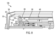
[0051]図7は、本開示の少なくとも幾つかの実施形態に係る裏側処理位置にある湿式洗浄チャンバ122bの一部を示す断面図である。裏側処理位置において、支持プレート512は、第2の種類の基板112bの裏側が、例えば、裏側流体源320からの裏側流体によって洗浄され得るように、バッキングテープ206から間隔を置いて配置されている。図8は、本開示の少なくとも幾つかの実施形態に係る表側処理位置にある湿式洗浄チャンバ122bの一部を示す断面図である。幾つかの実施形態では、表側処理位置において、支持プレート512は、バッキングテープ206に接触しており、バッキングテープ206を押し上げてバッキングテープ206のたるみを防止することができる。幾つかの実施形態では、図7に示すように、支持プレート512の上面716は平坦であってよい。幾つかの実施形態では、支持プレート512の上面716は湾曲していてよい、又はドーム状であってよい。
7 is a cross-sectional view of a portion of the
[0052]幾つかの実施形態では、支持プレート512は、テープフレーム基板、又は第2の種類の基板112bを支持プレート512から支持面710に沿って上昇させるように構成された複数の支持ピン704を含む。複数の支持ピン704の上部は、1又は複数の支持フィンガ460の支持面にアライメントされていてよい。図7及び図8に示すように、1又は複数のフックフィンガ518は、支持ピン704に対して第2の種類の基板112bをクランプするように構成されている。
[0052] In some embodiments, the
[0053]使用中、モータ250を上昇させて、基板支持体248bを上方の移送位置に持ち上げることができる。幾つかの実施形態では、1又は複数のフックフィンガ518の各々は、ベースプレート510の半径方向外側に延びる下部732を含む。移送位置にあるとき、ロータ304の外壁410は、バネ機構610のバイアス力に打ち勝って下部732に押し付けられ、1又は複数のフックフィンガ518の各々のヘッド720がピボット722の周囲を半径方向外側に旋回する。ヘッド720が外向きになった状態で、移送ロボット(図示せず)が、第2の種類の基板112bを複数の支持ピン704上に配置し得る。その後、モータ250を用いて基板支持体248bを下降させることができる。基板支持体248bが下降すると、1又は複数のフックフィンガ518が回転し、第2の種類の基板112bの上面に接触して、第2の種類の基板112bを把持又はクランプする。上方位置では、支持プレート512はベースプレート510上に載っていてよい。幾つかの実施形態では、支持プレート512は、ベースプレート510の上面の凹部712内に静止している。
[0053] In use, the
[0054]基板支持体248bが部分的に下降すると、支持プレート512は、例えば環状ベースプレート406の上面718に対して固く停止する。基板支持体248bが下降し続けると、支持プレート512はもはや垂直方向に移動しないため、第2の種類の基板112bの裏側が支持プレート512に接触してバッキングテープ206を支持する。支持プレート512はたるみを低減又は除去し、確実で安定した面を提供する。中心を支持せずにテープフレーム基板を高回転数で回転させると、テープと共にチップレットが大きく振動し、洗浄を予測することができず、ダイの剥離、粒子の形成、又は著しい飛散が生じる可能性がある。第2の種類の基板112bの表側の湿式洗浄プロセスの後、基板支持体248bを、支持プレート512がバッキングテープ206に接触しなくなるように部分的に上昇させることができる。この間隙により、裏側のリンス及びドライ(裏面処理)が可能になる。幾つかの実施形態では、表側のリンスは、裏側の処理と同時に行われ得る。幾つかの実施形態では、表裏のリンスが完了すると、ロータ304は高速ドライのために約2000RPMまで回転する。一旦処理されると、第2の種類の基板112bは持ち上げられ、湿式洗浄チャンバ122bから取り出され得る。
[0054] When the
[0055]図9は、本開示の少なくとも幾つかの実施形態に係る伸縮可能なカバー328Aを有する湿式洗浄チャンバ122の一部を示す概略断面図である。伸縮可能なカバー328Aは、湿式洗浄チャンバ122a又は第2の湿式洗浄チャンバ122bの「開いた」上部からの処理流体の飛散を更に低減又は防止するために有利に伸縮可能であってよく、本明細書に記載のチャンバのいずれにも実装され得る。幾つかの実装態様では、カバー328は、内側リング906及び外側リング912を含み、内側リング906又は外側リング912の一方は、内側リング906又は外側リング912の他方に対して上昇するように構成される。例えば、図9に示すように、内側リング906は、外側リング912の半径方向内側に配置され、1又は複数のアクチュエータ908を介して外側リング912に対して上昇するように構成されている。幾つかの実施形態では、1又は複数のアクチュエータ908は、デッキプレート220aに結合される。図9に、下方の、又は伸長されていない位置にある伸縮可能カバー328Aを示す。上方の、又は伸長位置では、内側リング906が外側リング912に対して持ち上げられ、更なる垂直方向の覆いを提供する。
[0055] FIG. 9 is a schematic cross-sectional view of a portion of the wet cleaning chamber 122 having an
[0056]幾つかの実施形態では、内側リング906は、内側リング906から半径方向外側に延びる1又は複数のタブ920に結合される。1又は複数のタブ920は、1又は複数のアクチュエータ908の対応するものに結合され、内側リング906の1又は複数のアクチュエータ908への結合を容易にする。幾つかの実施形態では、1又は複数のタブ920は、4つのタブを含み得る、又は4つのタブで構成され得る。幾つかの実施形態では、外側リング912は静止しており、アダプタリング904を介して本体326に結合されている。幾つかの実施形態では、内側リング906は、円筒形本体と、円筒形本体から半径方向内側に延び、ロータ304の第2の壁422の形状に対応する上部910とを含む。幾つかの実施形態では、上部910はくさび形である。幾つかの実施形態では、伸縮可能なカバー328Aは、更に50mm以上の垂直方向の覆いを提供する。
[0056] In some embodiments, the
[0057]前述の内容は本開示の実施形態を対象としているが、その基本的な範囲から逸脱することなく、本開示の他のさらなる実施形態を考案することが可能である。 [0057] While the foregoing is directed to embodiments of the present disclosure, other and further embodiments of the present disclosure may be devised without departing from the basic scope thereof.
Claims (20)
デッキプレートと、
回転可能であり、基板を支持するように構成された基板支持体と、
前記基板支持体の周囲に配置され、前記基板支持体と共に回転するように構成されたロータであって、前記ロータは、処理中に前記基板支持体から出る流体を回収する位置に、前記基板支持体の半径方向外側に配置された上部流体回収領域を含み、前記上部流体回収領域は、前記上部流体回収領域の底部の半径方向外側の周辺部に沿って複数のドレイン開口部を含む、ロータと、
前記ロータを取り囲み、前記ロータのドレイン開口部の下方に配置された下部流体回収領域を有する固定ハウジングと、
前記デッキプレートに結合され、前記基板に流体を供給するように構成された1又は複数の流体供給アームと
を備える、湿式洗浄チャンバ。 1. A wet cleaning chamber comprising:
Deck plate and
a substrate support configured to support a substrate and adapted to rotate;
a rotor disposed about the substrate support and configured to rotate with the substrate support, the rotor including an upper fluid recovery region disposed radially outward of the substrate support at a location to recover fluid exiting the substrate support during processing, the upper fluid recovery region including a plurality of drain openings along a radially outer periphery of a bottom of the upper fluid recovery region;
a stationary housing surrounding the rotor and having a lower fluid collection area disposed below a drain opening of the rotor;
one or more fluid delivery arms coupled to the deck plate and configured to deliver fluid to the substrate.
環状ベースプレートと、前記環状ベースプレートの外周から上方且つ半径方向内側に延びる外壁とを含み、前記環状ベースプレート及び前記外壁は前記上部流体回収領域を画定し、
前記固定ハウジングの下部及び前記環状ベースプレートの下面は、少なくとも部分的に前記下部流体回収領域を画定する、請求項1に記載の湿式洗浄チャンバ。 The rotor is
an annular base plate and an outer wall extending upwardly and radially inwardly from an outer periphery of the annular base plate, the annular base plate and the outer wall defining the upper fluid recovery area;
The wet clean chamber of claim 1 , wherein a lower portion of the stationary housing and a lower surface of the annular base plate at least partially define the lower fluid collection area.
基板支持体がウエハを支持するように構成されている、請求項1から6のいずれか一項に記載の湿式洗浄チャンバと、
第2の湿式洗浄チャンバであって、
デッキプレートと、
回転可能であり、支持面において基板を支持するように構成された基板支持体と、
前記基板支持体の周囲に配置され、前記基板支持体と共に回転するように構成されたロータであって、前記ロータは、処理中に前記基板支持体から出る流体を回収する位置に、前記基板支持体の半径方向外側に配置された上部流体回収領域を含み、前記上部流体回収領域は、前記上部流体回収領域の底部の半径方向外側の周辺部に沿って複数のドレイン開口部を含む、ロータと、
前記ロータを取り囲み、前記ロータのドレイン開口部の下方に配置された下部流体回収領域を有する固定ハウジングと、
前記デッキプレートに結合され、前記基板に流体を供給するように構成された1又は複数の流体供給アームと
を含む、第2の湿式洗浄チャンバと
前記湿式洗浄チャンバと前記第2の湿式洗浄チャンバとの間に配置された分離壁と
を備える、ツイン湿式洗浄チャンバ。 1. A twin wet cleaning chamber comprising:
7. The wet clean chamber of claim 1 , wherein the substrate support is configured to support a wafer;
a second wet clean chamber comprising:
Deck plate and
a substrate support that is rotatable and configured to support a substrate on a support surface;
a rotor disposed about the substrate support and configured to rotate with the substrate support, the rotor including an upper fluid recovery region disposed radially outward of the substrate support at a location to recover fluid exiting the substrate support during processing, the upper fluid recovery region including a plurality of drain openings along a radially outer periphery of a bottom of the upper fluid recovery region;
a stationary housing surrounding the rotor and having a lower fluid collection area disposed below a drain opening of the rotor;
a second wet clean chamber including one or more fluid delivery arms coupled to the deck plate and configured to deliver fluid to the substrate; and a separation wall disposed between the wet clean chamber and the second wet clean chamber.
1又は複数のロードポートを有するファクトリインターフェースと、
前記ファクトリインターフェースに結合された移送チャンバと、
前記移送チャンバに結合された請求項1から6のいずれか一項に記載の湿式洗浄チャンバと
を備える、マルチチャンバ処理ツール。 1. A multi-chamber processing tool, comprising:
a factory interface having one or more load ports;
a transfer chamber coupled to the factory interface;
A multi-chamber processing tool comprising: a wet clean chamber according to claim 1 coupled to the transfer chamber.
Applications Claiming Priority (5)
| Application Number | Priority Date | Filing Date | Title |
|---|---|---|---|
| US202163229922P | 2021-08-05 | 2021-08-05 | |
| US63/229,922 | 2021-08-05 | ||
| US17/880,212 US12460299B2 (en) | 2021-08-05 | 2022-08-03 | Wet clean spray process chamber for substrates |
| US17/880,212 | 2022-08-03 | ||
| PCT/US2022/074562 WO2023015270A1 (en) | 2021-08-05 | 2022-08-04 | Wet clean spray process chamber for substrates |
Publications (2)
| Publication Number | Publication Date |
|---|---|
| JP2024529007A JP2024529007A (en) | 2024-08-01 |
| JP7635463B2 true JP7635463B2 (en) | 2025-02-25 |
Family
ID=85152574
Family Applications (1)
| Application Number | Title | Priority Date | Filing Date |
|---|---|---|---|
| JP2024506800A Active JP7635463B2 (en) | 2021-08-05 | 2022-08-05 | Wet cleaning spray process chamber for substrates |
Country Status (7)
| Country | Link |
|---|---|
| US (1) | US12460299B2 (en) |
| EP (1) | EP4381539A4 (en) |
| JP (1) | JP7635463B2 (en) |
| KR (1) | KR20240033289A (en) |
| CN (1) | CN117941049A (en) |
| TW (1) | TW202314912A (en) |
| WO (1) | WO2023015270A1 (en) |
Families Citing this family (2)
| Publication number | Priority date | Publication date | Assignee | Title |
|---|---|---|---|---|
| US12400885B2 (en) * | 2022-03-11 | 2025-08-26 | Applied Materials, Inc. | Modular multi-chamber processing tool having link chamber for ultra high vacuum processes |
| US12481227B2 (en) * | 2022-11-28 | 2025-11-25 | Eclat Forever Machinery Co., Ltd. | Substrate processing apparatus |
Citations (4)
| Publication number | Priority date | Publication date | Assignee | Title |
|---|---|---|---|---|
| US20020051644A1 (en) | 2000-10-30 | 2002-05-02 | Dainippon Screen Mfg. Co., Ltd. | Substrate processing apparatus |
| JP2003059894A (en) | 2001-06-05 | 2003-02-28 | Dainippon Screen Mfg Co Ltd | Wafer processing system |
| US20120160277A1 (en) | 2010-12-28 | 2012-06-28 | Jiro Higashijima | Liquid Processing Apparatus and Liquid Processing Method |
| JP2015023138A (en) | 2013-07-18 | 2015-02-02 | 株式会社ディスコ | Spinner cleaning apparatus |
Family Cites Families (16)
| Publication number | Priority date | Publication date | Assignee | Title |
|---|---|---|---|---|
| EP1347496A3 (en) * | 2002-03-12 | 2006-05-03 | Dainippon Screen Mfg. Co., Ltd. | Substrate treating apparatus and substrate treating method |
| US7070660B2 (en) * | 2002-05-03 | 2006-07-04 | Asm America, Inc. | Wafer holder with stiffening rib |
| US7018555B2 (en) * | 2002-07-26 | 2006-03-28 | Dainippon Screen Mfg. Co., Ltd. | Substrate treatment method and substrate treatment apparatus |
| EP1833078B1 (en) * | 2004-07-09 | 2013-03-20 | Sekisui Chemical Co., Ltd. | Apparatus and method for processing the outer periphery of a substrate |
| US7806988B2 (en) | 2004-09-28 | 2010-10-05 | Micron Technology, Inc. | Method to address carbon incorporation in an interpoly oxide |
| CN100550291C (en) * | 2006-06-16 | 2009-10-14 | 东京毅力科创株式会社 | Liquid processing device and liquid processing method |
| US7694688B2 (en) | 2007-01-05 | 2010-04-13 | Applied Materials, Inc. | Wet clean system design |
| KR101467974B1 (en) | 2007-12-10 | 2014-12-10 | 에이씨엠 리서치 (상하이) 인코포레이티드 | Methods and apparatus for cleaning semiconductor wafers |
| KR101004434B1 (en) * | 2008-11-26 | 2010-12-28 | 세메스 주식회사 | Substrate support unit, substrate polishing apparatus and method using same |
| TWI667686B (en) * | 2015-01-23 | 2019-08-01 | 日本思可林集團股份有限公司 | Substrate processing method, substrate processing apparatus, and fluid nozzle |
| US9570334B2 (en) * | 2015-03-31 | 2017-02-14 | Taiwan Semiconductor Manufacturing Co., Ltd. | Method and system for positioning wafer in semiconductor manufacturing fabrication |
| US10155252B2 (en) | 2015-04-30 | 2018-12-18 | Taiwan Semiconductor Manufacturing Co., Ltd. | Semiconductor apparatus and washing method |
| US20170084470A1 (en) | 2015-09-18 | 2017-03-23 | Tokyo Electron Limited | Substrate processing apparatus and cleaning method of processing chamber |
| JP6559602B2 (en) * | 2015-09-18 | 2019-08-14 | 東京エレクトロン株式会社 | Substrate processing apparatus and processing chamber cleaning method |
| CN111633531B (en) | 2020-06-10 | 2022-03-04 | 华海清科股份有限公司 | Thinning equipment with single-cavity cleaning device |
| CN112735988B (en) | 2020-12-31 | 2022-12-20 | 至微半导体(上海)有限公司 | A composite cavity ultra-short stroke interleaving control method for wafer cleaning equipment |
-
2022
- 2022-08-03 US US17/880,212 patent/US12460299B2/en active Active
- 2022-08-04 WO PCT/US2022/074562 patent/WO2023015270A1/en not_active Ceased
- 2022-08-04 TW TW111129346A patent/TW202314912A/en unknown
- 2022-08-05 EP EP22854110.8A patent/EP4381539A4/en active Pending
- 2022-08-05 CN CN202280062014.9A patent/CN117941049A/en active Pending
- 2022-08-05 KR KR1020247006638A patent/KR20240033289A/en active Pending
- 2022-08-05 JP JP2024506800A patent/JP7635463B2/en active Active
Patent Citations (5)
| Publication number | Priority date | Publication date | Assignee | Title |
|---|---|---|---|---|
| US20020051644A1 (en) | 2000-10-30 | 2002-05-02 | Dainippon Screen Mfg. Co., Ltd. | Substrate processing apparatus |
| JP2003059894A (en) | 2001-06-05 | 2003-02-28 | Dainippon Screen Mfg Co Ltd | Wafer processing system |
| US20120160277A1 (en) | 2010-12-28 | 2012-06-28 | Jiro Higashijima | Liquid Processing Apparatus and Liquid Processing Method |
| JP2012142402A (en) | 2010-12-28 | 2012-07-26 | Tokyo Electron Ltd | Liquid processing apparatus and liquid processing method |
| JP2015023138A (en) | 2013-07-18 | 2015-02-02 | 株式会社ディスコ | Spinner cleaning apparatus |
Also Published As
| Publication number | Publication date |
|---|---|
| US20230040192A1 (en) | 2023-02-09 |
| EP4381539A4 (en) | 2025-08-13 |
| US12460299B2 (en) | 2025-11-04 |
| TW202314912A (en) | 2023-04-01 |
| WO2023015270A8 (en) | 2023-09-28 |
| CN117941049A (en) | 2024-04-26 |
| WO2023015270A1 (en) | 2023-02-09 |
| EP4381539A1 (en) | 2024-06-12 |
| JP2024529007A (en) | 2024-08-01 |
| KR20240033289A (en) | 2024-03-12 |
Similar Documents
| Publication | Publication Date | Title |
|---|---|---|
| US8974601B2 (en) | Apparatuses, systems and methods for treating substrate | |
| JP4939376B2 (en) | Substrate processing equipment | |
| JP7635463B2 (en) | Wet cleaning spray process chamber for substrates | |
| KR101946652B1 (en) | Substrate cleaning apparatus and substrate processing apparatus including the substrate cleaning apparatus | |
| US8631756B2 (en) | Apparatus for processing substrate and method of maintaining the apparatus | |
| US20140000659A1 (en) | Method and apparatus for processing substrate | |
| JP6320945B2 (en) | Substrate processing apparatus and substrate processing method | |
| JP7780635B2 (en) | Modular mainframe layout supporting multiple semiconductor process modules or chambers | |
| US20080156359A1 (en) | Systems and methods for modular and configurable substrate cleaning | |
| JP5726637B2 (en) | Liquid processing apparatus and liquid processing method | |
| KR20250133342A (en) | Integrated cleaning and drying module for cleaning substrates | |
| KR100819114B1 (en) | Substrate transfer robot and substrate processing apparatus including the same | |
| JP5191254B2 (en) | Substrate processing apparatus and substrate processing method | |
| JP2016149495A (en) | Substrate processing system and exhaust amount adjustment method in the system | |
| JP2025501168A (en) | FOUP or Cassette Storage for Hybrid Substrate Bonding System | |
| JP2023126087A (en) | Substrate processing equipment and semiconductor device manufacturing method | |
| KR20160149708A (en) | Dry and wet processing system using buffer chamber and substrate processing method thereof | |
| US20250170617A1 (en) | Substrate processing apparatus and substrate processing method | |
| US20240412986A1 (en) | Substrate processing apparatus and substrate processing method | |
| JP2012244128A (en) | Liquid processing apparatus and liquid processing method | |
| TW202442318A (en) | Substrate processing device and method for cleaning substrate processing device | |
| KR101940744B1 (en) | Apparatus for treating substrate | |
| KR20250128250A (en) | Substrate processing apparatus | |
| CN120033063A (en) | Apparatus and method for processing substrate | |
| KR20240043849A (en) | Apparatus for treating substrate and method for treating a substrate |
Legal Events
| Date | Code | Title | Description |
|---|---|---|---|
| A621 | Written request for application examination |
Free format text: JAPANESE INTERMEDIATE CODE: A621 Effective date: 20240314 |
|
| A977 | Report on retrieval |
Free format text: JAPANESE INTERMEDIATE CODE: A971007 Effective date: 20241212 |
|
| TRDD | Decision of grant or rejection written | ||
| A01 | Written decision to grant a patent or to grant a registration (utility model) |
Free format text: JAPANESE INTERMEDIATE CODE: A01 Effective date: 20250114 |
|
| A61 | First payment of annual fees (during grant procedure) |
Free format text: JAPANESE INTERMEDIATE CODE: A61 Effective date: 20250212 |
|
| R150 | Certificate of patent or registration of utility model |
Ref document number: 7635463 Country of ref document: JP Free format text: JAPANESE INTERMEDIATE CODE: R150 |