JP7635144B2 - Small volume liquid container - Google Patents
Small volume liquid container Download PDFInfo
- Publication number
- JP7635144B2 JP7635144B2 JP2021559938A JP2021559938A JP7635144B2 JP 7635144 B2 JP7635144 B2 JP 7635144B2 JP 2021559938 A JP2021559938 A JP 2021559938A JP 2021559938 A JP2021559938 A JP 2021559938A JP 7635144 B2 JP7635144 B2 JP 7635144B2
- Authority
- JP
- Japan
- Prior art keywords
- container
- shape
- liquid container
- stable
- small
- Prior art date
- Legal status (The legal status is an assumption and is not a legal conclusion. Google has not performed a legal analysis and makes no representation as to the accuracy of the status listed.)
- Active
Links
Images


Classifications
-
- A—HUMAN NECESSITIES
- A61—MEDICAL OR VETERINARY SCIENCE; HYGIENE
- A61M—DEVICES FOR INTRODUCING MEDIA INTO, OR ONTO, THE BODY; DEVICES FOR TRANSDUCING BODY MEDIA OR FOR TAKING MEDIA FROM THE BODY; DEVICES FOR PRODUCING OR ENDING SLEEP OR STUPOR
- A61M5/00—Devices for bringing media into the body in a subcutaneous, intra-vascular or intramuscular way; Accessories therefor, e.g. filling or cleaning devices, arm-rests
- A61M5/178—Syringes
- A61M5/24—Ampoule syringes, i.e. syringes with needle for use in combination with replaceable ampoules or carpules, e.g. automatic
- A61M5/2422—Ampoule syringes, i.e. syringes with needle for use in combination with replaceable ampoules or carpules, e.g. automatic using emptying means to expel or eject media, e.g. pistons, deformation of the ampoule, or telescoping of the ampoule
- A61M5/2425—Ampoule syringes, i.e. syringes with needle for use in combination with replaceable ampoules or carpules, e.g. automatic using emptying means to expel or eject media, e.g. pistons, deformation of the ampoule, or telescoping of the ampoule by compression of deformable ampoule or carpule wall
-
- A—HUMAN NECESSITIES
- A61—MEDICAL OR VETERINARY SCIENCE; HYGIENE
- A61M—DEVICES FOR INTRODUCING MEDIA INTO, OR ONTO, THE BODY; DEVICES FOR TRANSDUCING BODY MEDIA OR FOR TAKING MEDIA FROM THE BODY; DEVICES FOR PRODUCING OR ENDING SLEEP OR STUPOR
- A61M5/00—Devices for bringing media into the body in a subcutaneous, intra-vascular or intramuscular way; Accessories therefor, e.g. filling or cleaning devices, arm-rests
- A61M5/178—Syringes
- A61M5/28—Syringe ampoules or carpules, i.e. ampoules or carpules provided with a needle
- A61M5/281—Syringe ampoules or carpules, i.e. ampoules or carpules provided with a needle using emptying means to expel or eject media, e.g. pistons, deformation of the ampoule, or telescoping of the ampoule
- A61M5/282—Syringe ampoules or carpules, i.e. ampoules or carpules provided with a needle using emptying means to expel or eject media, e.g. pistons, deformation of the ampoule, or telescoping of the ampoule by compression of deformable ampoule or carpule wall
-
- B—PERFORMING OPERATIONS; TRANSPORTING
- B65—CONVEYING; PACKING; STORING; HANDLING THIN OR FILAMENTARY MATERIAL
- B65D—CONTAINERS FOR STORAGE OR TRANSPORT OF ARTICLES OR MATERIALS, e.g. BAGS, BARRELS, BOTTLES, BOXES, CANS, CARTONS, CRATES, DRUMS, JARS, TANKS, HOPPERS, FORWARDING CONTAINERS; ACCESSORIES, CLOSURES, OR FITTINGS THEREFOR; PACKAGING ELEMENTS; PACKAGES
- B65D83/00—Containers or packages with special means for dispensing contents
- B65D83/771—Containers or packages with special means for dispensing contents for dispensing fluent contents by means of a flexible bag or a deformable membrane or diaphragm
- B65D83/7713—Containers or packages with special means for dispensing contents for dispensing fluent contents by means of a flexible bag or a deformable membrane or diaphragm the contents of a flexible bag being expelled by a piston, or a movable bottom or partition provided in the container or the package
-
- C—CHEMISTRY; METALLURGY
- C12—BIOCHEMISTRY; BEER; SPIRITS; WINE; VINEGAR; MICROBIOLOGY; ENZYMOLOGY; MUTATION OR GENETIC ENGINEERING
- C12M—APPARATUS FOR ENZYMOLOGY OR MICROBIOLOGY; APPARATUS FOR CULTURING MICROORGANISMS FOR PRODUCING BIOMASS, FOR GROWING CELLS OR FOR OBTAINING FERMENTATION OR METABOLIC PRODUCTS, i.e. BIOREACTORS OR FERMENTERS
- C12M23/00—Constructional details, e.g. recesses, hinges
- C12M23/02—Form or structure of the vessel
- C12M23/06—Tubular
-
- C—CHEMISTRY; METALLURGY
- C12—BIOCHEMISTRY; BEER; SPIRITS; WINE; VINEGAR; MICROBIOLOGY; ENZYMOLOGY; MUTATION OR GENETIC ENGINEERING
- C12M—APPARATUS FOR ENZYMOLOGY OR MICROBIOLOGY; APPARATUS FOR CULTURING MICROORGANISMS FOR PRODUCING BIOMASS, FOR GROWING CELLS OR FOR OBTAINING FERMENTATION OR METABOLIC PRODUCTS, i.e. BIOREACTORS OR FERMENTERS
- C12M23/00—Constructional details, e.g. recesses, hinges
- C12M23/26—Constructional details, e.g. recesses, hinges flexible
-
- C—CHEMISTRY; METALLURGY
- C12—BIOCHEMISTRY; BEER; SPIRITS; WINE; VINEGAR; MICROBIOLOGY; ENZYMOLOGY; MUTATION OR GENETIC ENGINEERING
- C12M—APPARATUS FOR ENZYMOLOGY OR MICROBIOLOGY; APPARATUS FOR CULTURING MICROORGANISMS FOR PRODUCING BIOMASS, FOR GROWING CELLS OR FOR OBTAINING FERMENTATION OR METABOLIC PRODUCTS, i.e. BIOREACTORS OR FERMENTERS
- C12M23/00—Constructional details, e.g. recesses, hinges
- C12M23/28—Constructional details, e.g. recesses, hinges disposable or single use
-
- C—CHEMISTRY; METALLURGY
- C12—BIOCHEMISTRY; BEER; SPIRITS; WINE; VINEGAR; MICROBIOLOGY; ENZYMOLOGY; MUTATION OR GENETIC ENGINEERING
- C12M—APPARATUS FOR ENZYMOLOGY OR MICROBIOLOGY; APPARATUS FOR CULTURING MICROORGANISMS FOR PRODUCING BIOMASS, FOR GROWING CELLS OR FOR OBTAINING FERMENTATION OR METABOLIC PRODUCTS, i.e. BIOREACTORS OR FERMENTERS
- C12M23/00—Constructional details, e.g. recesses, hinges
- C12M23/34—Internal compartments or partitions
-
- C—CHEMISTRY; METALLURGY
- C12—BIOCHEMISTRY; BEER; SPIRITS; WINE; VINEGAR; MICROBIOLOGY; ENZYMOLOGY; MUTATION OR GENETIC ENGINEERING
- C12M—APPARATUS FOR ENZYMOLOGY OR MICROBIOLOGY; APPARATUS FOR CULTURING MICROORGANISMS FOR PRODUCING BIOMASS, FOR GROWING CELLS OR FOR OBTAINING FERMENTATION OR METABOLIC PRODUCTS, i.e. BIOREACTORS OR FERMENTERS
- C12M33/00—Means for introduction, transport, positioning, extraction, harvesting, peeling or sampling of biological material in or from the apparatus
- C12M33/04—Means for introduction, transport, positioning, extraction, harvesting, peeling or sampling of biological material in or from the apparatus by injection or suction, e.g. using pipettes, syringes, needles
-
- C—CHEMISTRY; METALLURGY
- C12—BIOCHEMISTRY; BEER; SPIRITS; WINE; VINEGAR; MICROBIOLOGY; ENZYMOLOGY; MUTATION OR GENETIC ENGINEERING
- C12M—APPARATUS FOR ENZYMOLOGY OR MICROBIOLOGY; APPARATUS FOR CULTURING MICROORGANISMS FOR PRODUCING BIOMASS, FOR GROWING CELLS OR FOR OBTAINING FERMENTATION OR METABOLIC PRODUCTS, i.e. BIOREACTORS OR FERMENTERS
- C12M35/00—Means for application of stress for stimulating the growth of microorganisms or the generation of fermentation or metabolic products; Means for electroporation or cell fusion
- C12M35/04—Mechanical means, e.g. sonic waves, stretching forces, pressure or shear stimuli
-
- C—CHEMISTRY; METALLURGY
- C12—BIOCHEMISTRY; BEER; SPIRITS; WINE; VINEGAR; MICROBIOLOGY; ENZYMOLOGY; MUTATION OR GENETIC ENGINEERING
- C12M—APPARATUS FOR ENZYMOLOGY OR MICROBIOLOGY; APPARATUS FOR CULTURING MICROORGANISMS FOR PRODUCING BIOMASS, FOR GROWING CELLS OR FOR OBTAINING FERMENTATION OR METABOLIC PRODUCTS, i.e. BIOREACTORS OR FERMENTERS
- C12M37/00—Means for sterilizing, maintaining sterile conditions or avoiding chemical or biological contamination
- C12M37/04—Seals
Landscapes
- Health & Medical Sciences (AREA)
- Life Sciences & Earth Sciences (AREA)
- Engineering & Computer Science (AREA)
- Zoology (AREA)
- Organic Chemistry (AREA)
- Bioinformatics & Cheminformatics (AREA)
- Chemical & Material Sciences (AREA)
- Wood Science & Technology (AREA)
- Biotechnology (AREA)
- Genetics & Genomics (AREA)
- General Health & Medical Sciences (AREA)
- Biomedical Technology (AREA)
- Biochemistry (AREA)
- Microbiology (AREA)
- General Engineering & Computer Science (AREA)
- Sustainable Development (AREA)
- Clinical Laboratory Science (AREA)
- Molecular Biology (AREA)
- Mechanical Engineering (AREA)
- Cell Biology (AREA)
- Anesthesiology (AREA)
- Heart & Thoracic Surgery (AREA)
- Hematology (AREA)
- Animal Behavior & Ethology (AREA)
- Public Health (AREA)
- Veterinary Medicine (AREA)
- Vascular Medicine (AREA)
- Apparatus Associated With Microorganisms And Enzymes (AREA)
- Containers And Packaging Bodies Having A Special Means To Remove Contents (AREA)
- External Artificial Organs (AREA)
- Medical Preparation Storing Or Oral Administration Devices (AREA)
Description
本発明は、請求項1の上位概念に記載の形式の、液体媒体を、バイオプロセス技術的な装置内に、特にバイオリアクタ内に供給するための少量液体容器、請求項13記載の、包装と、包装内に無菌に包装された液体容器とを備える包装アッセンブリ、ならびに請求項14記載の、無菌に包装されたこのような液体容器および/またはこのような包装アッセンブリの使用に関する。
The invention relates to a small-volume liquid container for supplying a liquid medium into a bioprocessing technical device, in particular into a bioreactor, of the type described in the preamble of
バイオプロセス技術的な装置とは、この場合、極めて一般的に、バイオ技術的プロセスを実施することができる、または支援することができる装置を意味している。ここでは単なる例として、バイオリアクタが挙げられており、バイオリアクタ内では、微生物または組織細胞が、予め規定された条件下で培養される。このような装置は、通常、容器を有しており、この容器内では、各バイオ技術的な方法ステップ、例えば発酵もしくは培養を実施することができるように、バイオ技術的プロセスのために設けられた材料、例えば一方では微生物または組織細胞、他方では相応の培地から生じる生物学的な反応媒体が収容される。 Bioprocessing equipment in this case means, quite generally, equipment in which a biotechnical process can be carried out or supported. Here, merely by way of example, a bioreactor is mentioned, in which microorganisms or tissue cells are cultivated under predefined conditions. Such equipment usually has a vessel in which the material provided for the biotechnical process, for example the microorganisms or tissue cells on the one hand and the biological reaction medium resulting from the corresponding culture medium on the other hand, is accommodated so that the respective biotechnical method step, for example fermentation or cultivation, can be carried out.
このようなバイオリアクタの例は、1つには生産用バイオリアクタであって、すなわち、微生物または細胞の製品、特にバイオ医薬品の工業生産のために、例えば数百リットルまたは数千リットルの作業容積を備えた生産規模の比較的大型のバイオリアクタである。このようなバイオリアクタは、生成物として発酵ブロスを形成し、これは通常、いわゆる下流プロセスでさらに処理されて、細胞または培地上澄みから製品を得る。別の例は、研究室用バイオリアクタであって、すなわち、例えば10リットル未満の作業容積を備えた研究室規模の比較的小型のバイオリアクタである。このような研究室用バイオリアクタは、例えばATMP(Advanced Therapy Medical Product、新規治療のための医薬品)の製造に用いられ、かつ/または各使用目的のために十分な数の細胞、特に組織細胞または微生物細胞を生成することができる細胞増殖を実施するために用いられる。このための1つの使用例は、患者から採取され、次いで生体外で増殖されて、次いで患者に再注入されるヒト細胞、例えば、T細胞(Tリンパ球)の増殖である。 Examples of such bioreactors are, on the one hand, production bioreactors, i.e. relatively large bioreactors of production scale with working volumes of, for example, hundreds or thousands of liters, for the industrial production of microbial or cellular products, in particular biopharmaceuticals. Such bioreactors form a fermentation broth as product, which is usually further processed in so-called downstream processes to obtain products from cells or culture supernatants. Another example is laboratory bioreactors, i.e. relatively small bioreactors of laboratory scale with working volumes of, for example, less than 10 liters. Such laboratory bioreactors are used, for example, for the production of ATMPs (Advanced Therapy Medical Products) and/or for carrying out cell proliferation, which can generate a sufficient number of cells, in particular tissue cells or microbial cells, for the respective intended use. One example of use for this is the proliferation of human cells, for example T cells (T lymphocytes), which are taken from a patient, then expanded ex vivo and then reinfused into the patient.
基本的には生産用バイオリアクタにおいても言えることであるが、研究室用バイオリアクタによるATMPの製造においては特に、例えば生物学的な個々の液体媒体を各バイオリアクタに可能な限り正確かつ精密に添加することが重要である。多くのATMPは、滅菌ろ過することができず、または最終的にろ過することができないので、このような医薬品の製造は、相応のクリーンルームクラスのクリーンルームで無菌式に行われる。すなわち、バイオリアクタへの液体媒体の添加または2つの培養容器および/またはバイオリアクタ間の液体媒体の移送は、基本的に汚染のリスクをもたらすので、このような取扱いステップは、通常、クリーンルームクラスA(GMPガイドラインアネックス1)またはISO5(ISO 14544-1)のクリーンルームで行われる。しかしながら、このようなクリーンルームにおける医薬品の製造には、高い監視要件、手間のかかる着衣手順等に起因して極めてコストがかかる。 In the production of ATMP in laboratory bioreactors, but also in production bioreactors, it is particularly important that the individual liquid media, for example biological, are added as accurately and precisely as possible to each bioreactor. Since many ATMPs cannot be sterile filtered or cannot be finally filtered, the production of such pharmaceutical products is carried out aseptically in clean rooms of the appropriate clean room class. That is, since the addition of liquid media to a bioreactor or the transfer of liquid media between two culture vessels and/or bioreactors essentially poses a risk of contamination, such handling steps are usually carried out in clean rooms of clean room class A (GMP guideline annex 1) or ISO 5 (ISO 14544-1). However, the production of pharmaceutical products in such clean rooms is very costly due to the high monitoring requirements, the laborious dressing procedures, etc.
このような理由から、特にATMPの製造分野では、より低いクリーンルームクラスのクリーンルーム、例えばクリーンルームクラスD(GMPガイドラインアネックス1)またはISO8(ISO 14644-1)のクリーンルームを使用することができる、細胞の培養もしくは増殖のためのクローズドシステムの需要がある。しかしながらこの場合、このようなクローズドシステムに、できるだけ簡単に液体媒体を添加するという課題がある。確かに、様々な少量液体容器が、すなわち、注射器またはバイアルのように、例えば、最大30mlの僅かな収容容積を備えた液体容器が公知ではある。しかしながら、このような液体容器からクローズドシステムへの液体媒体の移送には、しばしば、無菌コネクタ、無菌フィルタ等の多重使用が必要であり、これによりさらに手間とコストが増大する。 For this reason, particularly in the field of ATMP production, there is a demand for closed systems for culturing or growing cells, in which cleanrooms of lower cleanroom classes can be used, for example cleanrooms of cleanroom class D (GMP guidelines Annex 1) or ISO 8 (ISO 14644-1). In this case, however, there is the challenge of adding the liquid medium to such a closed system as simply as possible. Indeed, various small-volume liquid containers are known, i.e. liquid containers with a small capacity of, for example, up to 30 ml, such as syringes or vials. However, the transfer of the liquid medium from such liquid containers to the closed system often requires the multiple use of sterile connectors, sterile filters, etc., which further increases the effort and costs.
本発明の根底にある課題は、クローズドシステム内への液体媒体の添加が、エンドユーザにとって簡単になるように、少量液体容器を構成し、改良することである。 The problem underlying the present invention is to construct and improve a small volume liquid container such that adding liquid medium into a closed system is simplified for the end user.
上記課題は、請求項1の上位概念による、特に生物学的な液体媒体を供給するための少量液体容器において、請求項1の特徴部に記載の特徴により解決される。
The above problem is solved by the features of
使用者側で、クリーンルームにおいて、かつ/または無菌コネクタ、無菌フィルタ等を使用して、液体容器を充填する必要なしに、特に生物学的な液体媒体の正確な量を、バイオプロセス技術的な装置内に、特にバイオリアクタ内に、移送することができるようにする少量液体容器を設けるという基本的な考えが重要である。これは、各バイオ技術的プロセス、例えばATMP製造のために、エンドユーザに、予め充填された液体容器を提供するために、添加すべき液体媒体を簡単に、既に製造業者側で充填することができるように、提案による液体容器を構成することにより達成される。この目的のために、提案による液体容器は、互いの相対運動により収容容積から媒体を押し出すことができる2つの形状安定的な容器部分に加えて付加的に、媒体のための収容容積を画定するエレメントを有しており、このエレメントはその形状を、容器部分の相対運動により変化させる。以下で、形状変更可能な画定手段と呼称されるこのエレメントは、好適には柔軟な容器を形成し、この柔軟な容器には、製造業者側で簡単に、正確に必要量の液体媒体を無菌で充填することができ、次いで使用者側で、形状安定的な両容器部分の相対運動により簡単にこの容器を空にすることができる。 The basic idea is to provide a small volume liquid container, which allows a precise amount of liquid medium, in particular biological, to be transferred into a bioprocessing device, in particular into a bioreactor, without the need for the user to fill the liquid container in a clean room and/or using sterile connectors, sterile filters, etc. This is achieved by configuring the proposed liquid container in such a way that the liquid medium to be added can be filled simply and already at the manufacturer's side, in order to provide the end user with a pre-filled liquid container for the respective biotechnical process, for example ATMP production. For this purpose, the proposed liquid container has, in addition to two shape-stable container parts, which can push the medium out of the storage volume by a relative movement with respect to each other, an element that defines a storage volume for the medium, which element changes its shape by the relative movement of the container parts. This element, which will be referred to as a shape-changeable defining means in the following, forms a preferably flexible container, which can be simply filled aseptically by the manufacturer with the exact amount of liquid medium required, and which can then be simply emptied by the user by the relative movement of the two shape-stable container parts.
提案による手段により可能な製造業者側による充填は、まず、この場合、極めて多くの個数を工業条件のもとで自動的に製造することができ、これにより、手動の充填に比べて、汚染のリスクが著しく減じられるという利点を有している。さらに、これにより、正確に規定された量の液体媒体を液体容器に特に精密に充填することができ、この場合、個数が多い場合であっても、常に同じ量を保証することができる。最後に、個数が多いことにより、手動による充填と比較して、充填の手間も相応に減じられる。したがって、各収容容積の充填のみでも既に著しい利点が生じている。 Filling by the manufacturer, which is possible with the proposed solution, has the advantage, first of all, that extremely large quantities can be produced automatically under industrial conditions, which significantly reduces the risk of contamination compared to manual filling. Furthermore, this allows a particularly precise filling of precisely defined amounts of liquid medium into the liquid container, which ensures that the same amount is always filled, even in the case of large quantities. Finally, the large quantities also correspondingly reduce the effort required for filling compared to manual filling. Thus, significant advantages already result from the filling of the individual volumes alone.
しかしながらさらに、液体容器からクローズドシステム内への液体媒体の添加も著しく改善されている。すなわち、上述した通り、一方では、各液体容器は常に、正確に予め規定された量の液体媒体を含んでいることが保証されている。他方では、一連のバイオ技術的プロセスにおいて複数の液体容器が使用される場合、そのすべてが正確に同じ充填量を含んでいることが保証されている。最後に、収容容積が無菌条件下で充填されていて、特に好適には、形状安定的な容器部分も製造業者側で準備されて、エンドユーザに同様に無菌で提供されるので、特に高い無菌レベルも保証されている。したがって、提案による液体容器を、好適には液体媒体が既に正確に充填されているユニットとして、無菌に包装して、エンドユーザに提供することができる。このユニットは、好適には既に充填されて、無菌でユーザに提供されるので、ユーザ側では、液体媒体を液体容器からクローズドシステムへと移送する場合にのみ、無菌の接続を確保すればよい。 In addition, however, the addition of the liquid medium from the liquid container into the closed system is also significantly improved. That is to say, as mentioned above, on the one hand, it is guaranteed that each liquid container always contains exactly the predefined amount of liquid medium. On the other hand, it is guaranteed that, if several liquid containers are used in a series of biotechnical processes, they all contain exactly the same filling amount. Finally, a particularly high level of sterility is also guaranteed, since the storage volume is filled under sterile conditions and, particularly preferably, the form-stable container part is also prepared by the manufacturer and is likewise provided to the end user sterile. The proposed liquid container can therefore be provided to the end user in a sterile package, preferably as a unit already filled exactly with the liquid medium. This unit is preferably provided to the user already filled and sterile, so that the user only has to ensure a sterile connection when transferring the liquid medium from the liquid container to the closed system.
上記利点とは別に、提案により設けられた形状変更可能な画定手段により、続いて行われる廃棄の手間も僅かである。すなわち、特定の生物学的な媒体は、基本的に、人間および環境に危険をもたらすおそれがある。これを回避するために、この場合、提案による液体容器では、画定手段を簡単に、形状安定的な容器部分から分離して、別個に廃棄する、例えば焼却することができる。生物学的な媒体と接触していない形状安定的な容器部分は、滅菌後またはその他の不活化技術後に、再利用することができる。 Apart from the above mentioned advantages, the proposed deformable delimiting means also reduces the subsequent disposal effort, since certain biological media may fundamentally pose a danger to humans and the environment. To avoid this, in this case with the proposed liquid container the delimiting means can simply be separated from the form-stable container part and disposed of separately, for example by incineration. The form-stable container part which has not come into contact with the biological media can be reused after sterilization or other inactivation techniques.
詳細には、液体容器が、収容容積を少なくとも所定の区分で画定する、形状変更可能な画定手段を有していて、この画定手段は、収容容積の容積変化を生じさせる、形状安定的な容器部分の互いに対する相対運動が画定手段の形状変更を伴うように、形状安定的な容器部分に接続されていることが提案される。この場合、形状変更とは、それぞれ収容容積を画定している、画定手段の少なくとも2つの区分が、2つの形状安定的な容器部分の相対運動に基づき、その位置を互いに対して相対的に変更すること、特に互いに近付くように動かされることを意味する。形状変更の範囲で、その位置を変化させる画定手段の両区分は、互いに近付くように折り畳まれてよく、またはこれらが既に事前に、例えば蛇腹の場合のように、折り目の形態で配置されているならば、形状変更の範囲で、画定手段のこれら区分の間の、媒体が充填されている中間室は縮小されてよい。すなわち、形状変更は、特に、画定手段の材料の弾性変形を伴わない、またはいずれにせよ特筆すべき弾性変形を伴わない。 In particular, it is proposed that the liquid container has a shape-changeable delimiting means, which defines the storage volume at least in a certain section, and which is connected to the shape-stable container parts in such a way that a relative movement of the shape-stable container parts relative to one another, which causes a volume change of the storage volume, is accompanied by a shape change of the delimiting means. In this case, shape change means that at least two sections of the delimiting means, which respectively define the storage volume, change their position relative to one another, in particular are moved closer to one another, based on the relative movement of the two shape-stable container parts. In the scope of the shape change, both sections of the delimiting means which change their position can be folded closer to one another, or if they are already arranged beforehand in the form of folds, for example in the case of a bellows, in the scope of the shape change, the intermediate space between these sections of the delimiting means, which is filled with the medium, can be reduced. That is to say, the shape change is in particular not accompanied by an elastic deformation of the material of the delimiting means, or in any case not accompanied by a significant elastic deformation.
請求項2による特に好適な構成では、画定手段が収容容積を、少なくとも実質的に単独で画定している。この場合、「実質的に」とは、画定手段に開口が、特に排出開口が設けられてよく、この開口は、付加的なエレメント、例えば、ホースまたは小管のような延長部によって、液体媒体の供給時点まで閉鎖することができ、これにより、この場合、付加的なエレメントも、収容容積を画定する一部を形成していることを意味している。しかしながら、基本的には、画定手段が収容容積を完全に画定していて、いずれにせよ最初は、開口を有しておらず、液体媒体の供給の過程で初めて、例えば、目標破断個所に、排出開口が形成されることも考えられる。
In a particularly preferred embodiment according to
請求項3は、特に、画定手段が収容容積を、少なくとも実質的に単独で画定している場合の、画定手段の特に好適な構成を規定している。
請求項4および請求項5には、形状安定的な容器部分に対して相対的な画定手段の配置の特に好適な可能性が記載されている。
Claim 4 and
請求項6から請求項8は、形状安定的な容器部分の協働および構成の特に好適な可能性に関する。
請求項9および請求項10では、液体媒体の供給および場合によっては充填を可能にする、液体容器の特に好適な構成が規定されている。すなわち、画定手段および/または形状安定的な容器部分は、排出接続部および場合によっては充填接続部も形成することができる。 Claims 9 and 10 provide for particularly preferred configurations of the liquid container, which allow the supply and possibly filling of the liquid medium, i.e. the delimiting means and/or the form-stable container part can form the discharge connection and possibly also the filling connection.
請求項11における特に好適な構成によれば、提案による液体容器の収容容積には、既に液体媒体が、特に製造業者側で充填されている。 According to a particularly preferred embodiment of claim 11, the storage volume of the proposed liquid container is already filled with the liquid medium, in particular by the manufacturer.
請求項12は、形状安定的な容器部分の終端位置において、画定手段の材料によって側方で画定される空間内に突入する、一方または両方の形状安定的な容器部分における突出部を規定している。デッドスペースとも呼ばれるこの空間は、画定手段の材料が、例えば、蛇腹の折り畳まれた層が、終端位置で、所定の容積を占めており、完全に平坦には圧縮され得ないので、必然的に終端位置で残るものである。この残っている空間内に残留する液体媒体をできるだけ僅かにするために、収容容積の容積変更を生じさせる、形状安定的な容器部分の互いに対する相対運動の間に、突出部は、残っている空間内に侵入し、その中に存在している液体媒体を少なくとも大部分、実質的に完全に押しのける。 Claim 12 defines a protrusion in one or both of the form-stable container parts, which in the end positions of the form-stable container parts protrudes into a space laterally defined by the material of the delimiting means. This space, also called dead space, necessarily remains in the end positions, since the material of the delimiting means, for example the folded layers of a bellows, occupies a certain volume in the end positions and cannot be compressed completely flat. In order to leave as little liquid medium as possible in this remaining space, during a relative movement of the form-stable container parts relative to one another, which causes a volume change of the containment volume, the protrusion penetrates into the remaining space and displaces, at least for the most part, substantially completely, the liquid medium present therein.
独立的な意味を持つ請求項13による教示によれば、包装と、この包装内に無菌に包装された、提案による液体容器とを備えた包装アッセンブリが、それ自体、特許請求される。提案による包装アッセンブリが、提案による液体容器を有しているという事実を考えると、第1の教示に関する液体容器についてのすべての説明が参照されてよい。
According to the teaching of
同様に独立的な意味を持つ、請求項14によるさらなる教示によれば、特に生物学的な液体媒体を、バイオプロセス技術的な装置内に、特にバイオリアクタ内に添加するための、無菌に包装された提案による液体容器および/または提案による包装アッセンブリの使用が、特許請求される。提案による使用が、提案による液体容器および/または提案による包装アッセンブリの使用に関係するという事実を考えると、第1および第2の教示に関する液体容器および包装アッセンブリについてのすべての説明が参照されてよい。
According to the further teaching according to
提案による包装アッセンブリおよび提案による使用によれば、液体容器をエンドユーザに既に無菌の状態で提供することにより、提案による液体容器によって、液体媒体を特に簡単に、特筆すべき汚染のリスクなく、クローズドシステムに、特にバイオリアクタに供給することができることがわかる。特に好適には、提案による液体容器は、既に述べたように、この状態で既に充填もされている。 It turns out that the proposed packaging assembly and the proposed use allow the liquid container to be supplied to a closed system, in particular a bioreactor, in a particularly simple manner and without any significant risk of contamination, by providing the liquid container to the end user already in a sterile state. Particularly preferably, the proposed liquid container is also already filled in this state, as already mentioned.
請求項15による特に好適な構成では、提案による液体容器の個々のまたはすべての構成要素は、好適にはシングルユース構成要素として形成されており、これらの構成要素は好適にはプラスチック材料から形成されている。
In a particularly preferred configuration according to
次に本発明を、単なる実施例を示す図面につき詳しく説明する。 The invention will now be described in more detail with reference to the drawings, which are merely examples.
図1~図6において様々な実施例で示された、提案による少量液体容器1は、製造業者側によって予め充填された、この場合、生物学的な液体媒体を、バイオプロセス技術的な装置内に、特に、クローズドシステムを形成する、またはクローズドシステム内に組み込まれているバイオリアクタ内に供給するために用いられる。ここでは、見易さのために図示されていないバイオリアクタは、例えば、研究室用バイオリアクタとして構成されており、すなわち、生産用バイオリアクタとは異なり、最大10リットルの比較的小さな作業容積(使用可能な最大充填容積)を有するバイオリアクタとして構成されている。このようなバイオリアクタは、この場合、好適には、新規治療のための医薬品(ATMP)の製造に役立つバイオ技術的なプロセスの実施のために用いられる。例えば、バイオ技術的なプロセスは、T細胞のための細胞増殖プロセスであってもよい。いずれにせよ、バイオリアクタ内には、特に、組織細胞または微生物細胞ならびに培地を有する生物学的な反応媒体が設けられている。この場合、液体媒体を、クローズドシステムに、無菌かつ正確な投与量で添加する必要がある。
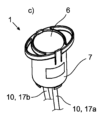
The proposed small-
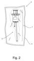
この目的のために特に、提案による液体容器1が設けられている。この容器は、液体媒体のための収容容積2を提供する。この場合、液体媒体は、製造業者によって既に、予め規定された量で、無菌条件下で収容容積2内に充填されており、この場合、その他の部分でも無菌の液体容器1は、続いて無菌に包装されている。このように無菌に包装されて、予め充填された状態で、提案による液体容器1は、次いで、エンドユーザに提供される。図2には、この例として、包装4と、この包装内に無菌で包装された提案による液体容器1とを備えた包装アッセンブリ3が示されている。液体容器1は、図2に示されたように、既に完全に予め組み立てられており、この場合、好適には、シングルユースユニット5として構成されていて、すなわち、全体の構成要素がシングルユース構成要素(使い捨て構成要素)であるユニット5として構成されている。シングルユースユニット5を相応に交換する場合には、相互汚染のリスクが著しく減じられる。
For this purpose, in particular, a proposed
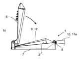
提案による液体容器1はさらに、特に図3~図6に示したように、始端位置と終端位置との間で互いに相対的に可動な、2つの形状安定的な容器部分6,7と、液体媒体を導出するための排出接続部8とを有している。始端位置は、とりわけ図4のa)、図5のb)、および図6のb)に示したように、収容容積2が最大のサイズを有している位置を、もしくは収容容積2に、バイオプロセス技術的な装置への供給のために予め規定された充填量の液体媒体が充填されている位置を意味している。終端位置は、とりわけ図4のb)、図5のc)、および図6のc)に示したように、相応に、収容容積2が最小のサイズを有している位置を、もしくは収容容積2から、予め規定された量の液体媒体が導出された位置を意味している。
The proposed
ここで重要であるのは、提案による液体容器1が、収容容積2を少なくとも所定の区分で画定する、形状変更可能な画定手段9を有していて、この画定手段は、収容容積2の容積変化を生じさせる、形状安定的な容器部分6,7の互いに対する相対運動が、画定手段9の形状変更を伴うように、形状安定的な容器部分6,7に接続されているということである。
What is important here is that the proposed
すなわち、画定手段9は、それぞれ図4のa)およびb)、図5のb)およびc)、または図6のb)およびc)にまとめて示されているように、容器部分6が容器部分7に対して相対的に、この場合は手動で力を加えることにより、移動させられることによってその形状を変化させられ、これにより、この場合、好適には、容器部分6は容器部分7の方向に動かされる。これに伴う画定手段9の形状変更の直接的な結果として、収容容積2のサイズの変化が、すなわち、この場合、収容容積2のサイズの減少が生じる。これにより、収容容積2から、したがって提案された液体容器1から液体媒体が排出接続部8を介して導出される。提案による液体容器1は、既に、製造業者側で予め規定された量の液体媒体が充填されていて、無菌に包装されているので、バイオプロセス技術的な装置、この場合、バイオリアクタへの液体媒体の添加は、極めて精密である。さらに、エンドユーザ自身が少量液体容器1を現場で充填する必要はないので、液体媒体の汚染のリスクは著しく減じられる。液体容器1からクローズドシステムに液体媒体を移す場合にのみ、なお、エンドユーザは、無菌接続を確保する必要がある。このような無菌接続は、例えば、液体容器1を、もしくはさらに詳しく後述する容器側のホースを、バイオプロセス技術的な装置にもしくは装置側のホースに無菌に流体密に連結する無菌コネクタを介して製作することができる。代替的には、最初に密封されているこのような容器側のホースを、相応に同様に最初は密封されている、装置側もしくはリアクタ側のホースに、無菌の溶接工程で液密に連結することができる。
That is, the delimiting means 9 is changed in shape by displacing the
この場合、好適には、画定手段9が収容容積2を、少なくとも実質的には単独で画定している。排出接続部8を介して液体容器1および/または画定手段9に連結されている、さらに詳しく後述する延長部10だけは、この場合、収容容積2の画定部の部分でもある。すなわち、収容容積2は、この場合、好適には、画定手段9の内側および延長部10の内側に延在している。しかしなら基本的には、ここに図示されていない代替的な構成では、収容容積2が、一方または両方の容器部分6,7と共に画定手段9によって少なくともほぼ完全に画定されることも考えられる。しかしながら画定手段9が完全にまたはいずれにせよ実質的に完全に収容容積2を形成するならば、これにより、画定手段9を、形状安定的な容器部分6,7とは独立的に充填し、廃棄することができるので、好適である。容器部分6,7はこのようにして、画定手段9の充填後に、画定手段と共にガイドされてよく、この場合、画定手段9は、好適には容器部分6,7の間に配置される。液体媒体の供給後は、画定手段9を必要に応じて容器部分6,7から分離することができ、画定手段9を廃棄した後は、容器部分6,7を再利用することができる。
In this case, the delimiting means 9 preferably defines the receiving
図1~図4の実施例では、画定手段9は、ベローズ11であって、この場合、好適には蛇腹である。容器部分6,7間の上述した相対運動により、ベローズ11もしくは蛇腹は、この場合、排出接続部8の方向で圧縮されて、特にアコーディオンの原理で圧縮されて、これにより液体媒体は、排出接続部8を介して流出する。
In the embodiment of Figs. 1 to 4, the delimiting means 9 is a bellows 11, in this case preferably a bellows. Due to the above-mentioned relative movement between the
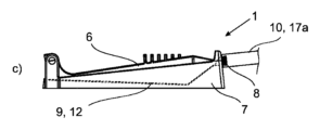
図3のc)に概略的に示したように、液体容器1の好適な構成では、この場合、上側の形状安定的な容器部分6に、突出部18が設けられていてよく、この突出部は、容器部分6,7の終端位置で、画定手段9の、この場合、蛇腹の折り目の材料によって、側方で画定される空間内に突入する。この場合、「側方で」とは、容器部分が互いに相対的に移動する方向に対して横方向の方向を意味している。突出部18は、出発位置で、形状変更可能な画定手段9および/または収容容積2に面した突出部18であって、特に容器部分6に材料接続的に結合されているか、またはこの容器部分と一体に形成されている。すなわち、収容容積2の容積変更を生じさせる、容器部分6,7の互いに対する相対運動の間に、突出部18は、残っている空間(デッドスペース)内に侵入し、その中に存在している液体媒体を少なくとも大部分、実質的に完全に押しのける。
3 c), in a preferred configuration of the
図5の実施例でも、液体媒体を導出するために容器部分6,7を介して圧縮されるベローズ11が、画定手段9として設けられている。しかしながら、この場合、容器部分6,7の間の上述した相対運動により、ベローズ11は、排出接続部8に向かってではなく、排出接続部8を中心とする方向で圧縮される。したがって、ベローズ11は、この場合、形状安定的な容器部分6,7と共に、ふいごの原理で構成されており、すなわち、ベローズ11は、始端位置では、排出接続部8とは反対側で、排出接続部8に面した側よりも厚くなっていて、終端位置では、両側はほぼ同じ厚さである。しかしながら、基本的には、図5の実施例では特に、画定手段9として、容器部分6,7を互いに密に接続する単に1つのダイヤフラムを設けることも考えられる。
In the embodiment of FIG. 5, a bellows 11 is also provided as the delimiting means 9, which is compressed via the
図5のb)に概略的に示したように、この場合も、液体容器1の好適な構成では、少なくとも1つの形状安定的な容器部分6,7に、この場合は、上側の形状安定的な容器部分6と、下側の形状安定的な容器部分7との両方に、突出部18が設けられていてよく、この突出部は、容器部分6,7の終端位置で、画定手段9の、この場合、ふいごの折り目の材料によって、側方で画定されている空間内に突入する。この場合も、「側方で」とは、容器部分が互いに相対的に移動する方向に対して横方向の方向を意味している。この場合、上記の空間は、画定手段9の材料の、この場合、ふいごの折り目の側でのみ、側方で画定される。突出部18は、同様にそれぞれ、出発位置で、形状変更可能な画定手段9および/または収容容積2に面した突出部18であって、特に各容器部分6,7に材料接続的に結合されているか、またはこれらの容器部分と一体に形成されている。すなわち、この場合、収容容積2の容積変更を生じさせる、容器部分6,7の互いに対する相対運動の間に、両突出部18は、残っている空間(デッドスペース)内に侵入し、その中に存在している液体媒体を少なくとも大部分、実質的に完全に押しのける。この場合、例えば容器部分6のみに設けられている1つだけの突出部18が設けられていてもよいことに注意されたい。
5b), in a preferred configuration of the
図6の実施例では、画定手段9は、液体媒体を導出するために容器部分6,7の互いに対して相対的な運動によりに絞り出されるチューブ12である。この場合も、ベローズ11は、容器部分6,7の間の上述した相対運動により、排出接続部8に向かってではなく、排出接続部8を中心とする方向で圧縮される。
In the embodiment of FIG. 6, the delimiting means 9 is a tube 12 that is squeezed by the relative movement of the
この場合、必須ではないが、基本的には、この場合も、液体容器1の好適な構成では、少なくとも1つの形状安定的な容器部分6,7に、突出部(図示せず)が設けられていてよく、この突出部は、容器部分6,7の終端位置で、画定手段9の材料によって側方で画定されている空間内に突入する。
In this case, although not essential, in principle, also in this case, in a preferred configuration of the
画定手段9、すなわちこの場合、好適にはベローズ11またはチューブ12は、この実施例ではそれぞれ取外し可能に、特に形状接続的に、形状安定的な容器部分6,7の少なくとも一方に、かつ/または両形状安定的な容器部分6,7の間に装着されている。これにより、収容容積2もしくは画定手段9の分離された充填およびその後のそれらの廃棄が容易になる。しかしながら基本的には、代替的な、ここには図示されていない構成において、画定手段9を堅固に、すなわち破壊せずにはもはや取外し不可能であるように、特に材料接続的に、容器部分6,7の少なくとも一方に、好適には両容器部分6,7に接続することも考えられる。
The delimiting means 9, i.e. in this case preferably the bellows 11 or the tube 12, is in this embodiment removably, in particular form-tightly, attached to at least one of the form-
図4に示したような第1の実施例では、形状安定的な両容器部分6,7は、互いに直線的に移動可能である。これらの容器部分は、この場合、好適には、シリンダ・ピストン装置13を形成し、この場合、図4の上側の容器部分6はピストン13aを、下側の容器部分7はシリンダ13bを形成し、このシリンダ内でピストン13aが直線運動可能である。これに対して、図5および図6の実施例では、形状安定的な容器部分6,7は、互いに相対的に旋回可能である。図5の実施例では、形状安定的な容器部分6,7の少なくとも一方が、もしくはこの場合、好適には両方が板状に形成されている。「板状」とは、これら容器部分が、その延在全体にわたって、実質的に同じ厚さを有していて、実質的に1つの平面に沿って延在していることを意味する。図6の実施例では、形状安定的な容器部分6,7の少なくとも一方が、シェル状に形成されている。この場合、「シェル状」とは、各容器部分6,7が、図6の場合にチューブ12である画定手段9を内部に装着することができる収容スペースを画定していることを意味している。基本的には、図5および図6による実施例の場合のような、提案による液体容器1では、好適には、いずれにせよ、容器部分6,7の少なくとも一方の、好適には両容器部分6,7の、画定手段9および/または収容容積2に面した側が、画定手段9に当接するために最適な当接面を形成するために実質的に平坦であると好適である。
In the first embodiment as shown in FIG. 4, the two shape-
提案による液体容器1では、図4のb)、図5のc)、および図6のc)に示したような終端位置において、形状安定的な容器部分6が、他方の形状安定的な容器部分7に、始端位置の方向で形状接続的に保持されるならばさらに好適である。単なる例であるが、この目的で、ロック部材が挙げられ、このロック部材は、この場合、図1による実施例についてのみ示されているが、他の実施例でも設けることができる。
It is furthermore preferred if in the proposed
この場合、好適には、図4のb)に示したように、容器部分のうちの一方が、この場合、下側の容器部分7が、1つ以上の係止突起14aを有していて、それぞれ他方の容器部分が、この場合、上側の容器部分6が、これと係止するように協働する対応部材14bを有している。次いで、形状安定的な容器部分6,7が、始端位置(図4のa))から終端位置(図4のb))へと動かされると、対応部材14bは、各係止突起14aに沿って通過するようにガイドされ、これにより終端位置で係止結合部14が形成される。このような係止結合部14には、液体媒体の供給後、場合によっては生じる、特に画定手段9の弾性的な戻り変形に基づき媒体が、収容容積2内に吸い戻されるおそれがないという利点がある。
In this case, preferably, as shown in FIG. 4b), one of the container parts, in this case the
図4にはさらに、固定部材15が、この場合、軸方向の固定部材15が示されており、これは、容器部分6,7が始端位置で互いに分離され得ることを阻止している。このために、この場合も同様に、別の対応部材15aと形状接続的に協働する係止突起14aが機能する。
Figure 4 further shows a
図3にさらに示したように、ここに図示した第1の実施例では、排出接続部8は、画定手段9に、この場合、ベローズ11に形成されている。この場合、好適には、付加的に、画定手段9もしくはベローズ11には、特に製造業者側による収容容積2への液体媒体の充填のための充填接続部16も設けられている。図5および図6における実施例でも、排出接続部8は画定手段9に形成されている。しかしながら、この場合は、付加的な充填接続部は設けられていない。付加的にまたは代替的に、排出接続部8を、形状安定的な容器部分6,7の一方に設けることもできる。
As further shown in FIG. 3, in the first embodiment shown here, the
各排出接続部8には、第1の実施例では、充填接続部16にも、この場合、好適には、上述した延長部10を形成するホース17a,17bまたは小管が連結されている。この場合、ホース17a,17bもしくは小管を介して、液体媒体を収容容積2から導出することができる、もしくは収容容積内に、製造業者側で導入することができる。ホース17a,17bまたは小管の、それぞれ液体容器1とは反対側の端部は、この場合、好適には、製造業者側で封止されていて、特に溶接されている。液体媒体の供給のために、この封止は、例えば、上述した無菌の溶接工程の範囲で、事前に除去されて、各ホース17a,17bは、別の、好適には装置側のもしくはリアクタ側のホース(図示せず)に、流体技術的に接続される。
In the first embodiment, each
さらなる好適な実施形態では、ホース17a,17bは、既に製造業者側で、無菌コネクタの連結装置に接続されていて、この無菌コネクタは、装置側のもしくはリアクタ側のホースに接続されている対応する連結装置に、無菌で流体技術的に連結することができる。 In a further preferred embodiment, the hoses 17a, 17b are already connected at the manufacturer to a sterile connector connection device, which can be connected in a sterile and fluid-technical manner to a corresponding connection device that is connected to the hose on the device side or on the reactor side.
収容容積2は、この場合、好適には、始端位置で、収容容積2内の液体媒体量が、この場合、好適には、50mlまでの、好適には40mlまでの、さらに好適には30mlまでの最大充填量であるようなサイズである。
The
独立的な意味を持つさらなる教示によれば、図2に例として示されている包装アッセンブリ3は、包装4と、この包装内に無菌に包装された、提案による液体容器1とを備えていて、それ自体、特許請求される。上述したように、この場合、包装アッセンブリ3が、既に充填された状態の液体容器1を保持していると、好適である。これについては、提案による液体容器1に関するすべての説明が参照されてよい。
According to further teachings having an independent meaning, the
この場合、好適には、包装4には、容器部分6,7と、画定手段9、特にベローズ11と、それぞれホース17a,17bまたは小管の形態の延長部10とが包装されている。ここには図示されていない代替的な実施形態では、提案による包装アッセンブリ3は、包装4において無菌に包装されて、専ら、好適には予め充填された、場合によっては延長部10もしくは各ホース17a,17bまたは小管を備えた、画定手段9のみを有していることも考えられる。形状安定的な容器部分6,7は、この場合、別個の包装内で無菌に包装されて、またはエンドユーザによって、準備されてもよい。
In this case, preferably, the packaging 4 contains the
同様に独立的な意味を持つさらなる教示によれば、液体媒体をバイオプロセス技術的な装置内に、特にバイオリアクタ内に添加するための、無菌に包装された提案による液体容器1および/または提案による包装アッセンブリ3の使用は、それ自体、特許請求される。特許請求される使用に関しても、提案による液体容器1および提案による包装アッセンブリ3についてのすべての説明が参照されてよい。
According to further teachings which likewise have an independent meaning, the use of the proposed
液体容器1を包装4から取り出した後、液体容器は、この場合、延長部10もしくは各ホース17a,17bまたは小管を介して、各バイオプロセス技術的な装置に接続される。
After removing the
特に好適な構成では、少なくとも画定手段9は、好適には少なくとも1つの形状安定的な容器部分6,7も、特に両方の形状安定的な容器部分6,7も、および/またはホース17a,17bまたは小管も、それぞれシングルユース構成要素である。各構成要素、すなわち、画定手段9、各形状安定的な容器部分6,7、および/または各ホース17a,17bもしくは各小管は、少なくとも部分的に、好適には少なくともほぼ、プラスチック材料から構成されている。画定手段9は、好適にはプラスチックフィルムから形成される。個々の構成要素のためのプラスチック材料としては、特に、シリコン材料および/またポリマ材料が適している。その例は、PE(ポリエチレン)、PP(ポリプロピレン)、PTFE(ポリテトラフルオロエチレン)、PBT(ポリブチレンテレフタレート)、PSU(ポリスルホン)、PESU(ポリエーテルスルホン)、PC(ポリカーボネート)である。
In a particularly preferred configuration, at least the delimiting means 9, preferably also at least one form-
Claims (25)
前記少量液体容器(1)は、始端位置と終端位置との間で互いに相対的に可動な、2つの形状安定的な容器部分(6,7)と、前記液体媒体を導出するための排出接続部(8)とを有しており、
前記少量液体容器(1)は、前記収容容積(2)を少なくとも所定の区分で画定する、形状変更可能な画定手段(9)を有していて、前記画定手段は、前記収容容積(2)の容積変化を生じさせる、前記形状安定的な容器部分(6,7)の互いに対する相対運動が前記画定手段(9)の形状変更を伴うように、前記形状安定的な容器部分(6,7)に接続されている、少量液体容器(1)において、
前記終端位置において、一方の前記形状安定的な容器部分(6)は、他方の前記形状安定的な容器部分(7)に、前記始端位置の方向に移動しないように、形状接続的に保持されることを特徴とする、少量液体容器(1)。 A small volume container (1) for supplying a liquid medium into a bioprocessing technical device, said small volume container (1) providing a receiving volume (2) for said liquid medium,
The liquid container (1) has two shape-stable container parts (6, 7) which are movable relative to one another between a start position and a end position and a discharge connection (8) for discharging the liquid medium,
The small volume liquid container (1) has shape-changeable delimiting means (9) for delimiting the storage volume (2) at least in a predetermined section, the delimiting means being connected to the shape-stable container parts (6, 7) in such a way that a relative movement of the shape-stable container parts (6, 7) relative to one another, which causes a volume change of the storage volume (2), is accompanied by a shape change of the delimiting means (9),
The small-volume liquid container (1) is characterized in that, in the end position, one of the shape-stable container parts (6) is form-lockingly held to the other shape-stable container part (7) so as not to move in the direction of the start position.
Applications Claiming Priority (3)
| Application Number | Priority Date | Filing Date | Title |
|---|---|---|---|
| DE102019109493.3 | 2019-04-10 | ||
| DE102019109493.3A DE102019109493A1 (en) | 2019-04-10 | 2019-04-10 | Small volume liquid container |
| PCT/EP2020/060198 WO2020208160A1 (en) | 2019-04-10 | 2020-04-09 | Shortfall quantity liquid container |
Publications (2)
| Publication Number | Publication Date |
|---|---|
| JP2022528550A JP2022528550A (en) | 2022-06-14 |
| JP7635144B2 true JP7635144B2 (en) | 2025-02-25 |
Family
ID=70391080
Family Applications (1)
| Application Number | Title | Priority Date | Filing Date |
|---|---|---|---|
| JP2021559938A Active JP7635144B2 (en) | 2019-04-10 | 2020-04-09 | Small volume liquid container |
Country Status (10)
| Country | Link |
|---|---|
| US (1) | US12545874B2 (en) |
| EP (1) | EP3953446A1 (en) |
| JP (1) | JP7635144B2 (en) |
| KR (1) | KR102918241B1 (en) |
| CN (1) | CN113631697A (en) |
| CA (1) | CA3135467A1 (en) |
| DE (1) | DE102019109493A1 (en) |
| IL (1) | IL287068B2 (en) |
| SG (1) | SG11202111194SA (en) |
| WO (1) | WO2020208160A1 (en) |
Families Citing this family (1)
| Publication number | Priority date | Publication date | Assignee | Title |
|---|---|---|---|---|
| DE102019109493A1 (en) | 2019-04-10 | 2020-10-15 | Sartorius Stedim Biotech Gmbh | Small volume liquid container |
Citations (6)
| Publication number | Priority date | Publication date | Assignee | Title |
|---|---|---|---|---|
| JP2004018504A (en) | 2002-06-20 | 2004-01-22 | Jms Co Ltd | Cell storage container |
| WO2005037984A1 (en) | 2003-10-20 | 2005-04-28 | Jms Co., Ltd. | Cell handling device, human tissue regeneration composition, and human tissue regeneration method |
| JP2013523202A (en) | 2010-03-25 | 2013-06-17 | ニュー インジェクション システムズ リミテッド | Syringe |
| JP2016049313A (en) | 2014-09-01 | 2016-04-11 | 株式会社アクアテック | Liquid discharge device |
| JP2017127283A (en) | 2016-01-22 | 2017-07-27 | 株式会社日立製作所 | Device for processing cultured product, method for processing cultured product, and apparatus for purifying cultured product |
| JP2018520691A (en) | 2015-07-29 | 2018-08-02 | ヴェストファーレン ヴィルヘルム−ウニヴェルジテート ミュンスター | Apparatus and method for treating liquids, especially body fluids |
Family Cites Families (27)
| Publication number | Priority date | Publication date | Assignee | Title |
|---|---|---|---|---|
| CH468196A (en) * | 1967-06-17 | 1969-02-15 | Stato Ag | Device for performing a medicinal injection |
| DE2638200A1 (en) * | 1976-08-25 | 1978-03-09 | Rido Busse | Blow moulded or injection moulded synthetic material syringe ampoule - is emptied via injection needle by applying pressure externally to concertina shaped cylinder |
| US4411656A (en) | 1982-01-29 | 1983-10-25 | Urologic & Enteric Research Associates | Compressible syringe |
| DE3377399D1 (en) | 1982-05-12 | 1988-08-25 | Fresenius Ag | Sterile container for medical use |
| DE3420865C1 (en) * | 1984-06-05 | 1985-08-29 | B. Braun Melsungen Ag, 3508 Melsungen | Infusion syringe pump |
| ATA228987A (en) * | 1987-09-09 | 1993-07-15 | Pickhard Ewald | INJECTION DEVICE WITH A DEFORMABLE Vial |
| DE4340082A1 (en) * | 1993-11-24 | 1995-06-22 | Juergen Noack | Disposable single use syringe |
| US6319235B1 (en) * | 1995-09-08 | 2001-11-20 | Koichi Yoshino | Syringe serving also as an ampule and associated equipment |
| AU7145896A (en) * | 1995-10-09 | 1997-04-30 | Takeda Chemical Industries Ltd. | Injector |
| JP4133071B2 (en) | 2001-08-20 | 2008-08-13 | 大成化工株式会社 | Anti-sagging injector, and plunger and seal body for the injector |
| WO2008033872A2 (en) | 2006-09-12 | 2008-03-20 | Vidacare Corporation | Biopsy devices and related methods |
| US20040035743A1 (en) * | 2002-08-22 | 2004-02-26 | Gerry Tighe | System, methods and apparatus for administering medical liquids |
| FR2843739B1 (en) | 2002-08-23 | 2006-02-10 | Valois Sa | FLUID PRODUCT DISPENSER |
| DE10337484B4 (en) * | 2003-08-14 | 2005-05-25 | Zengerle, Roland, Prof. Dr. | Microdosing device and method for the metered dispensing of liquids |
| US7356999B2 (en) * | 2003-10-10 | 2008-04-15 | York International Corporation | System and method for stability control in a centrifugal compressor |
| CN100497580C (en) * | 2003-10-20 | 2009-06-10 | 株式会社Jms | Cell handling device, tissue regeneration composition, and tissue regeneration method |
| ITMI20060676A1 (en) * | 2006-04-06 | 2007-10-07 | Fabrizio Costa | UNIVERSAL EXPULSION DEVICE DOSED FOR TOOTHPASTE TUBE |
| EP2401008B1 (en) * | 2009-02-04 | 2015-01-21 | Mallinckrodt LLC | Hand-actuated syringe with vacuum chamber for auto refill |
| US20110087173A1 (en) | 2009-10-12 | 2011-04-14 | Sibbitt Jr Wilmer L | Automatic syringes |
| US20110196379A1 (en) * | 2009-12-03 | 2011-08-11 | David Blakemore | Bone cement injector assembly and method of use |
| US9180252B2 (en) * | 2012-04-20 | 2015-11-10 | Bayer Medical Care Inc. | Bellows syringe fluid delivery system |
| CN203123203U (en) * | 2013-02-04 | 2013-08-14 | 中国人民解放军第三军医大学第一附属医院 | Automatic limiting injector |
| CN204352310U (en) * | 2014-12-24 | 2015-05-27 | 金富康 | Without silicone oil syringe |
| US20210102876A1 (en) * | 2017-03-02 | 2021-04-08 | Hero Scientific Ltd. | Testing for particulates |
| KR102134037B1 (en) * | 2017-08-18 | 2020-07-14 | 주식회사 쟈마트메디칼 | A Accordion syringe to prevent restoration |
| CN208552832U (en) * | 2018-01-10 | 2019-03-01 | 程洪英 | A kind of tumor marker syringe |
| DE102019109493A1 (en) | 2019-04-10 | 2020-10-15 | Sartorius Stedim Biotech Gmbh | Small volume liquid container |
-
2019
- 2019-04-10 DE DE102019109493.3A patent/DE102019109493A1/en active Pending
-
2020
- 2020-04-09 US US17/600,938 patent/US12545874B2/en active Active
- 2020-04-09 SG SG11202111194SA patent/SG11202111194SA/en unknown
- 2020-04-09 IL IL287068A patent/IL287068B2/en unknown
- 2020-04-09 JP JP2021559938A patent/JP7635144B2/en active Active
- 2020-04-09 WO PCT/EP2020/060198 patent/WO2020208160A1/en not_active Ceased
- 2020-04-09 CN CN202080027343.0A patent/CN113631697A/en active Pending
- 2020-04-09 CA CA3135467A patent/CA3135467A1/en active Pending
- 2020-04-09 EP EP20720755.6A patent/EP3953446A1/en active Pending
- 2020-04-09 KR KR1020217036583A patent/KR102918241B1/en active Active
Patent Citations (6)
| Publication number | Priority date | Publication date | Assignee | Title |
|---|---|---|---|---|
| JP2004018504A (en) | 2002-06-20 | 2004-01-22 | Jms Co Ltd | Cell storage container |
| WO2005037984A1 (en) | 2003-10-20 | 2005-04-28 | Jms Co., Ltd. | Cell handling device, human tissue regeneration composition, and human tissue regeneration method |
| JP2013523202A (en) | 2010-03-25 | 2013-06-17 | ニュー インジェクション システムズ リミテッド | Syringe |
| JP2016049313A (en) | 2014-09-01 | 2016-04-11 | 株式会社アクアテック | Liquid discharge device |
| JP2018520691A (en) | 2015-07-29 | 2018-08-02 | ヴェストファーレン ヴィルヘルム−ウニヴェルジテート ミュンスター | Apparatus and method for treating liquids, especially body fluids |
| JP2017127283A (en) | 2016-01-22 | 2017-07-27 | 株式会社日立製作所 | Device for processing cultured product, method for processing cultured product, and apparatus for purifying cultured product |
Also Published As
| Publication number | Publication date |
|---|---|
| CA3135467A1 (en) | 2020-10-15 |
| US20220195362A1 (en) | 2022-06-23 |
| EP3953446A1 (en) | 2022-02-16 |
| IL287068B2 (en) | 2026-04-01 |
| US12545874B2 (en) | 2026-02-10 |
| SG11202111194SA (en) | 2021-11-29 |
| JP2022528550A (en) | 2022-06-14 |
| IL287068B1 (en) | 2025-12-01 |
| CN113631697A (en) | 2021-11-09 |
| WO2020208160A1 (en) | 2020-10-15 |
| KR102918241B1 (en) | 2026-01-26 |
| KR20210151164A (en) | 2021-12-13 |
| IL287068A (en) | 2021-12-01 |
| DE102019109493A1 (en) | 2020-10-15 |
Similar Documents
| Publication | Publication Date | Title |
|---|---|---|
| US20220260189A1 (en) | Sterile connector for the sterile transfer of a liquid medium | |
| JP6129208B2 (en) | Multiple dose vials and methods | |
| US20130319575A1 (en) | Bag for distributing a product for biopharmaceutical use in the general state of a liquid or paste via a plurality of outlet ports | |
| CA2937901C (en) | Multi-dose disposable system | |
| RU2592666C2 (en) | Syringe for multiple doses and method | |
| JP7092681B2 (en) | Septam holder with movable septum | |
| EP3652287A1 (en) | Upstream and downstream processing within single-use containers | |
| US20060069356A1 (en) | Plunger for a syringe and syringe | |
| JP2023506603A (en) | assembly | |
| JP7635144B2 (en) | Small volume liquid container | |
| US20110192489A1 (en) | Method and device for transferring a substance between closed systems | |
| WO2015160563A1 (en) | Reconstitution of pharmaceuticals for injection | |
| JP7219978B2 (en) | Attachment for perfusion culture | |
| US12194281B2 (en) | Syringe, syringe assembly, and manufacturing method of syringe | |
| WO2016205787A1 (en) | Containers for closed system single-use bioreactors and culture vessels | |
| JP7624165B2 (en) | Container for biological material with instruments | |
| JP2022125689A (en) | Cell storage container and manufacturing method of cell storage container | |
| US20260055354A1 (en) | Method of assembling a bioreactor having a biological material depositing end that is movable with the top portion to allow bioprinting | |
| US20240009400A1 (en) | Sterile sampling methods and devices for automated cell engineering systems | |
| JP2021184709A (en) | Device and method for loading cells into implantable device | |
| JPWO2022077026A5 (en) |
Legal Events
| Date | Code | Title | Description |
|---|---|---|---|
| A621 | Written request for application examination |
Free format text: JAPANESE INTERMEDIATE CODE: A621 Effective date: 20230315 |
|
| A977 | Report on retrieval |
Free format text: JAPANESE INTERMEDIATE CODE: A971007 Effective date: 20240214 |
|
| A131 | Notification of reasons for refusal |
Free format text: JAPANESE INTERMEDIATE CODE: A131 Effective date: 20240219 |
|
| A601 | Written request for extension of time |
Free format text: JAPANESE INTERMEDIATE CODE: A601 Effective date: 20240520 |
|
| A521 | Request for written amendment filed |
Free format text: JAPANESE INTERMEDIATE CODE: A523 Effective date: 20240627 |
|
| A131 | Notification of reasons for refusal |
Free format text: JAPANESE INTERMEDIATE CODE: A131 Effective date: 20241002 |
|
| A521 | Request for written amendment filed |
Free format text: JAPANESE INTERMEDIATE CODE: A523 Effective date: 20241202 |
|
| TRDD | Decision of grant or rejection written | ||
| A01 | Written decision to grant a patent or to grant a registration (utility model) |
Free format text: JAPANESE INTERMEDIATE CODE: A01 Effective date: 20250114 |
|
| A61 | First payment of annual fees (during grant procedure) |
Free format text: JAPANESE INTERMEDIATE CODE: A61 Effective date: 20250212 |
|
| R150 | Certificate of patent or registration of utility model |
Ref document number: 7635144 Country of ref document: JP Free format text: JAPANESE INTERMEDIATE CODE: R150 |