JP7621690B2 - Blood flow measurement system - Google Patents
Blood flow measurement system Download PDFInfo
- Publication number
- JP7621690B2 JP7621690B2 JP2023563933A JP2023563933A JP7621690B2 JP 7621690 B2 JP7621690 B2 JP 7621690B2 JP 2023563933 A JP2023563933 A JP 2023563933A JP 2023563933 A JP2023563933 A JP 2023563933A JP 7621690 B2 JP7621690 B2 JP 7621690B2
- Authority
- JP
- Japan
- Prior art keywords
- doppler
- probe
- blood flow
- ultrasound
- signal
- Prior art date
- Legal status (The legal status is an assumption and is not a legal conclusion. Google has not performed a legal analysis and makes no representation as to the accuracy of the status listed.)
- Active
Links
Images

Classifications
-
- A—HUMAN NECESSITIES
- A61—MEDICAL OR VETERINARY SCIENCE; HYGIENE
- A61B—DIAGNOSIS; SURGERY; IDENTIFICATION
- A61B8/00—Diagnosis using ultrasonic, sonic or infrasonic waves
- A61B8/06—Measuring blood flow
-
- A—HUMAN NECESSITIES
- A61—MEDICAL OR VETERINARY SCIENCE; HYGIENE
- A61B—DIAGNOSIS; SURGERY; IDENTIFICATION
- A61B8/00—Diagnosis using ultrasonic, sonic or infrasonic waves
- A61B8/08—Clinical applications
- A61B8/0891—Clinical applications for diagnosis of blood vessels
-
- A—HUMAN NECESSITIES
- A61—MEDICAL OR VETERINARY SCIENCE; HYGIENE
- A61B—DIAGNOSIS; SURGERY; IDENTIFICATION
- A61B8/00—Diagnosis using ultrasonic, sonic or infrasonic waves
- A61B8/44—Constructional features of the ultrasonic, sonic or infrasonic diagnostic device
- A61B8/4477—Constructional features of the ultrasonic, sonic or infrasonic diagnostic device using several separate ultrasound transducers or probes
-
- A—HUMAN NECESSITIES
- A61—MEDICAL OR VETERINARY SCIENCE; HYGIENE
- A61B—DIAGNOSIS; SURGERY; IDENTIFICATION
- A61B8/00—Diagnosis using ultrasonic, sonic or infrasonic waves
- A61B8/44—Constructional features of the ultrasonic, sonic or infrasonic diagnostic device
- A61B8/4483—Constructional features of the ultrasonic, sonic or infrasonic diagnostic device characterised by features of the ultrasound transducer
- A61B8/4494—Constructional features of the ultrasonic, sonic or infrasonic diagnostic device characterised by features of the ultrasound transducer characterised by the arrangement of the transducer elements
-
- A—HUMAN NECESSITIES
- A61—MEDICAL OR VETERINARY SCIENCE; HYGIENE
- A61B—DIAGNOSIS; SURGERY; IDENTIFICATION
- A61B8/00—Diagnosis using ultrasonic, sonic or infrasonic waves
- A61B8/48—Diagnostic techniques
- A61B8/488—Diagnostic techniques involving Doppler signals
-
- A—HUMAN NECESSITIES
- A61—MEDICAL OR VETERINARY SCIENCE; HYGIENE
- A61B—DIAGNOSIS; SURGERY; IDENTIFICATION
- A61B8/00—Diagnosis using ultrasonic, sonic or infrasonic waves
- A61B8/52—Devices using data or image processing specially adapted for diagnosis using ultrasonic, sonic or infrasonic waves
- A61B8/5207—Devices using data or image processing specially adapted for diagnosis using ultrasonic, sonic or infrasonic waves involving processing of raw data to produce diagnostic data, e.g. for generating an image
-
- A—HUMAN NECESSITIES
- A61—MEDICAL OR VETERINARY SCIENCE; HYGIENE
- A61B—DIAGNOSIS; SURGERY; IDENTIFICATION
- A61B8/00—Diagnosis using ultrasonic, sonic or infrasonic waves
- A61B8/52—Devices using data or image processing specially adapted for diagnosis using ultrasonic, sonic or infrasonic waves
- A61B8/5215—Devices using data or image processing specially adapted for diagnosis using ultrasonic, sonic or infrasonic waves involving processing of medical diagnostic data
- A61B8/5223—Devices using data or image processing specially adapted for diagnosis using ultrasonic, sonic or infrasonic waves involving processing of medical diagnostic data for extracting a diagnostic or physiological parameter from medical diagnostic data
-
- A—HUMAN NECESSITIES
- A61—MEDICAL OR VETERINARY SCIENCE; HYGIENE
- A61B—DIAGNOSIS; SURGERY; IDENTIFICATION
- A61B8/00—Diagnosis using ultrasonic, sonic or infrasonic waves
- A61B8/54—Control of the diagnostic device
Landscapes
- Health & Medical Sciences (AREA)
- Life Sciences & Earth Sciences (AREA)
- Engineering & Computer Science (AREA)
- Surgery (AREA)
- General Health & Medical Sciences (AREA)
- Pathology (AREA)
- Radiology & Medical Imaging (AREA)
- Biophysics (AREA)
- Biomedical Technology (AREA)
- Heart & Thoracic Surgery (AREA)
- Medical Informatics (AREA)
- Molecular Biology (AREA)
- Physics & Mathematics (AREA)
- Animal Behavior & Ethology (AREA)
- Nuclear Medicine, Radiotherapy & Molecular Imaging (AREA)
- Public Health (AREA)
- Veterinary Medicine (AREA)
- Gynecology & Obstetrics (AREA)
- Hematology (AREA)
- Computer Vision & Pattern Recognition (AREA)
- Vascular Medicine (AREA)
- Physiology (AREA)
- Ultra Sonic Daignosis Equipment (AREA)
- Measuring Pulse, Heart Rate, Blood Pressure Or Blood Flow (AREA)
Description
本発明は、血流測定システムに関する。 The present invention relates to a blood flow measurement system.
既存の肺動脈カテーテルは、非常に侵襲的な方法で肺動脈破裂などの合併症の危険が存在し、食道ドップラーは、最小侵襲的であり、持続的な血流測定が可能であるが、断層面の面積とドップラー入射角の情報が不在で信頼性が劣るという欠点がある。最近、このような問題を解決するために、様々な研究が行われている。 Existing pulmonary artery catheters are highly invasive methods that carry the risk of complications such as pulmonary artery rupture, while esophageal Doppler is minimally invasive and allows for continuous blood flow measurement, but has the disadvantage of being less reliable due to the lack of information on the cross-sectional area and Doppler incidence angle. Recently, various research efforts have been conducted to solve these problems.
本発明が解決しようとする技術的課題は、ガイド映像プローブから対象体に送信超音波信号を提供し、ガイド映像プローブ、第1ドップラープローブおよび第2ドップラープローブを介して同時に受信される受信超音波信号に基づいて血管の位置を把握し、血流速度を測定することにより、超音波装置を駆動するためのパルス繰り返し周波数(Pulse Repetition Frequency;PRF)を著しく高めることができる血流測定システムを提供することである。 The technical problem to be solved by the present invention is to provide a blood flow measurement system that can significantly increase the pulse repetition frequency (PRF) for driving an ultrasound device by providing a transmitted ultrasound signal from a guide imaging probe to a subject, determining the position of blood vessels based on received ultrasound signals simultaneously received through the guide imaging probe, a first Doppler probe, and a second Doppler probe, and measuring the blood flow velocity.
このような課題を解決するために、本発明の実施形態による血流測定システムは、ガイド映像プローブ、第1ドップラープローブ、第2ドップラープローブおよび制御部を含むことができる。ガイド映像プローブは、複数の映像超音波エレメントを含み、第1方向に沿って配置されることができる。第1ドップラープローブは、複数の第1ドップラー超音波エレメントを含み、前記第1方向と垂直な方向に該当する第2方向に沿って前記ガイド映像プローブの一側に配置されることができる。第2ドップラープローブは、複数の第2ドップラー超音波エレメントを含み、前記第1方向と垂直な方向に該当する第3方向に沿って前記ガイド映像プローブの他側に配置されることができる。制御部は、前記ガイド映像プローブ、前記第1ドップラープローブおよび前記第2ドップラープローブを制御する制御信号を提供することができる。 To solve this problem, a blood flow measurement system according to an embodiment of the present invention may include a guide image probe, a first Doppler probe, a second Doppler probe, and a control unit. The guide image probe may include a plurality of image ultrasound elements and be arranged along a first direction. The first Doppler probe may include a plurality of first Doppler ultrasound elements and be arranged on one side of the guide image probe along a second direction corresponding to a direction perpendicular to the first direction. The second Doppler probe may include a plurality of second Doppler ultrasound elements and be arranged on the other side of the guide image probe along a third direction corresponding to a direction perpendicular to the first direction. The control unit may provide a control signal for controlling the guide image probe, the first Doppler probe, and the second Doppler probe.
一実施形態において、前記制御部が提供する前記制御信号のうち第1制御信号に基づいて、前記ガイド映像プローブは、対象体に送信超音波信号を提供し、前記ガイド映像プローブ、前記第1ドップラープローブおよび前記第2ドップラープローブは、前記対象体から反射する受信超音波信号を受信することができる。 In one embodiment, based on a first control signal among the control signals provided by the control unit, the guide image probe provides a transmitted ultrasound signal to a target body, and the guide image probe, the first Doppler probe, and the second Doppler probe can receive a received ultrasound signal reflected from the target body.
一実施形態において、前記血流測定システムは、検出部をさらに含むことができる。検出部は、前記受信超音波信号のうち前記ガイド映像プローブに受信される映像超音波受信信号に基づいて、対象体に含まれる血管の位置情報を検出することができる。 In one embodiment, the blood flow measurement system may further include a detection unit. The detection unit may detect position information of blood vessels included in the target object based on an imaging ultrasound reception signal received by the guide imaging probe among the received ultrasound signals.
一実施形態において、前記検出部は、測定部をさらに含むことができる。測定部は、前記血管の位置情報および超音波映像の深さ方向に形成される横断面ガイドラインに沿って前記血管の横断面の面積に該当する横断面積を測定することができる。 In one embodiment, the detection unit may further include a measurement unit. The measurement unit may measure a cross-sectional area corresponding to the cross-sectional area of the blood vessel according to the position information of the blood vessel and a cross-sectional guideline formed in the depth direction of the ultrasound image.
一実施形態において、前記血流測定システムは、算出部をさらに含むことができる。算出部は、前記受信超音波信号のうち前記第1ドップラープローブに受信される第1ドップラー超音波受信信号および前記受信超音波信号のうち前記第2ドップラープローブに受信される第2ドップラー超音波受信信号に基づいて血流速度を算出することができる。 In one embodiment, the blood flow measurement system may further include a calculation unit. The calculation unit may calculate the blood flow velocity based on a first Doppler ultrasound reception signal received by the first Doppler probe among the received ultrasound signals and a second Doppler ultrasound reception signal received by the second Doppler probe among the received ultrasound signals.
一実施形態において、前記制御部は、選択部をさらに含むことができる。選択部は、前記制御信号のうち選択信号に基づいて、前記第1ドップラープローブおよび前記第2ドップラープローブを選択的に駆動することができる。 In one embodiment, the control unit may further include a selection unit. The selection unit may selectively drive the first Doppler probe and the second Doppler probe based on a selection signal among the control signals.
一実施形態において、前記選択部は、予め定められた所定の時間間隔に該当する駆動間隔ごとに前記第1ドップラープローブおよび前記第2ドップラープローブを交互に駆動することができる。 In one embodiment, the selection unit can alternately drive the first Doppler probe and the second Doppler probe at each drive interval that corresponds to a predetermined time interval.
一実施形態において、前記血流測定システムは、複数の動作モードで動作することができる。前記検出部が前記血管の位置情報を検出する場合、前記複数の動作モードのうち第1動作モードでは、前記制御部は、前記送信超音波信号を送信する間隔に該当する送信間隔を順に増加させることができる。 In one embodiment, the blood flow measurement system can operate in a plurality of operation modes. When the detection unit detects position information of the blood vessel, in a first operation mode among the plurality of operation modes, the control unit can sequentially increase a transmission interval corresponding to an interval at which the transmitted ultrasound signal is transmitted.
一実施形態において、前記検出部が前記血管の位置情報を検出する場合、前記複数の動作モードのうち第2動作モードでは、前記制御部は、前記第1ドップラープローブおよび前記第2ドップラープローブを駆動して、第1ドップラー超音波送信信号および第2ドップラー超音波送信信号を前記対象体に含まれる前記血管に交互に送信することができる。 In one embodiment, when the detection unit detects position information of the blood vessel, in a second operation mode among the plurality of operation modes, the control unit can drive the first Doppler probe and the second Doppler probe to alternately transmit a first Doppler ultrasound transmission signal and a second Doppler ultrasound transmission signal to the blood vessel included in the target body.
一実施形態において、前記血流測定システムは、前記第1ドップラー超音波送信信号が前記血管から反射して第1ドップラープローブに受信される第1ドップラー超音波受信信号および前記第2ドップラー超音波送信信号が前記血管から反射して第2ドップラープローブに受信される第2ドップラー超音波受信信号に基づいて、前記血流速度を算出することができる。 In one embodiment, the blood flow measurement system can calculate the blood flow velocity based on a first Doppler ultrasound reception signal, which is the first Doppler ultrasound transmission signal reflected from the blood vessel and received by a first Doppler probe, and a second Doppler ultrasound reception signal, which is the second Doppler ultrasound transmission signal reflected from the blood vessel and received by a second Doppler probe.
上記で言及された本発明の技術的課題の他にも、本発明の他の特徴および利点が、以下で記述されるか、そのような技術および説明から本発明が属する技術分野において通常の知識を有する者が明確に理解することができる。 In addition to the technical problems of the present invention mentioned above, other features and advantages of the present invention will be described below or will be clearly understood by those having ordinary skill in the art to which the present invention pertains from such techniques and explanations.
以上のような本発明によると、以下のような効果がある。 The present invention as described above has the following advantages:
本発明による血流測定システムは、ガイド映像プローブから対象体に送信超音波信号を提供し、ガイド映像プローブ、第1ドップラープローブおよび第2ドップラープローブを介して同時に受信される受信超音波信号に基づいて血管の位置を把握し、血流速度を測定することで超音波装置を駆動するためのパルス繰り返し周波数(Pulse Repetition Frequency;PRF)を著しく高めることができる。 The blood flow measurement system according to the present invention provides a transmitted ultrasound signal from a guide imaging probe to a subject, and determines the position of blood vessels and measures the blood flow velocity based on the received ultrasound signals simultaneously received through the guide imaging probe, the first Doppler probe, and the second Doppler probe, thereby significantly increasing the pulse repetition frequency (PRF) for driving an ultrasound device.
その他にも、本発明の実施形態により、本発明のさらに他の特徴および利点が新たに把握されることもできる。 In addition, other features and advantages of the present invention may be newly realized through the embodiments of the present invention.
本明細書において、各図面の構成要素に参照番号を付けるに際し、同じ構成要素に限っては、仮に異なる図面上に表示されていても、できるだけ同じ番号を有するようにしていることに留意すべきである。 In this specification, when assigning reference numbers to components in each drawing, it should be noted that, as far as possible, identical components are numbered the same even if they appear on different drawings.
一方、本明細書に述べられている用語の意味は、以下のように理解すべきである。 Meanwhile, the meanings of the terms used in this specification should be understood as follows:
単数の表現は、文脈上、明白に異なる意味で定義しない限り、複数の表現を含むものと理解すべきであり、これらの用語によって権利範囲が限定されてはならない。 Unless the context clearly defines a different meaning, singular expressions should be understood to include plural expressions, and the scope of rights should not be limited by these terms.
「含む」または「有する」などの用語は、一つまたはそれ以上の他の特徴や数字、ステップ、動作、構成要素、部分品またはこれらを組み合わせたものなどの存在または付加可能性を予め排除しないことを理解すべきである。 It should be understood that terms such as "comprise" or "have" do not preclude the presence or possibility of one or more other features, numbers, steps, operations, components, parts, or combinations thereof.
以下、添付の図面を参照して、上記問題点を解決するために考案された本発明の好ましい実施形態について詳細に説明する。 Below, we will explain in detail the preferred embodiment of the present invention, which has been devised to solve the above problems, with reference to the attached drawings.
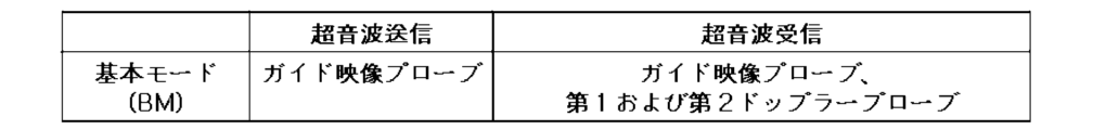
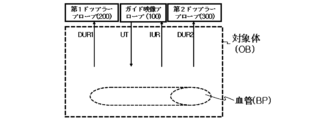
図1は、本発明の実施形態による血流測定システムを示す図であり、図2は、図1の血流測定システムの動作モードのうち基本モードを説明するための図であり、図3は、図1の血流測定システムに含まれるガイド映像プローブ、第1ドップラープローブおよび第2ドップラープローブの動作を説明するための図である。 Figure 1 shows a blood flow measurement system according to an embodiment of the present invention, Figure 2 is a diagram for explaining a basic mode among the operating modes of the blood flow measurement system of Figure 1, and Figure 3 is a diagram for explaining the operation of the guide image probe, first Doppler probe, and second Doppler probe included in the blood flow measurement system of Figure 1.
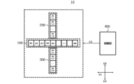
図1~図3を参照すると、本発明の実施形態による血流測定システム10は、ガイド映像プローブ100、第1ドップラープローブ200、第2ドップラープローブ300および制御部400を含むことができる。ガイド映像プローブ100は、複数の映像超音波エレメントを含み、第1方向D1に沿って配置されることができる。例えば、第1方向D1は、図1を基準に左右方向を示すことができ、映像超音波エレメントは、第1映像超音波エレメントIE1、第2映像超音波エレメントIE2~第N映像超音波エレメントIENを含むことができる。本発明による血流測定システム10は、ガイド映像プローブ100を介して超音波送信信号UTを対象体OBに送信し、対象体OBから反射して受信される映像超音波受信信号IURを用いて、超音波映像UIを実現することができる。ここで、対象体OBは、人体の一部分であることができる。
Referring to FIG. 1 to FIG. 3, the blood
第1ドップラープローブ200は、複数の第1ドップラー超音波エレメントを含み、第1方向D1と垂直な方向に該当する第2方向D2に沿ってガイド映像プローブ100の一側に配置されることができる。例えば、第1ドップラープローブ200は、ガイド映像プローブ100を基準に、第2方向D2に配置されることができ、第1ドップラー超音波エレメントは、第1_1ドップラー超音波エレメントDE1_1、第1_2ドップラー超音波エレメントDE1_2~第1_Kドップラー超音波エレメントDE1_Kを含むことができる。ここで、Kは、自然数であることができ、Kは、自然数Nと同一であってもよく、相違していてもよい。本発明による血流測定システム10は、第1ドップラープローブ200を介して対象体OBから反射して受信される第1ドップラー超音波受信信号DUR1を用いて、対象体OB内部血管BPの第1血流速度を示すスペクトログラムを算出することができる。
The first Doppler
第2ドップラープローブ300は、複数の第2ドップラー超音波エレメントを含み、第1方向D1と垂直な方向に該当する第3方向D3に沿ってガイド映像プローブ100の他側に配置されることができる。例えば、第2ドップラープローブ300は、ガイド映像プローブ100を基準に、第3方向D3に配置されることができ、第2ドップラー超音波エレメントは、第2_1ドップラー超音波エレメントDE2_1、第2_2ドップラー超音波エレメントDE2_2~第2_Jドップラー超音波エレメントDE2_Jを含むことができる。ここで、Jは、自然数であることができ、Jは、自然数NまたはKと同一であってもよく、相違していてもよい。本発明による血流測定システム10は、第2ドップラープローブ300を介して対象体OBから反射して受信される第2ドップラー超音波受信信号DUR2を用いて、対象体OBの内部血管BPの第2血流速度を示すスペクトログラムを算出することができる。
The second Doppler
制御部400は、ガイド映像プローブ100、第1ドップラープローブ200および第2ドップラープローブ300を制御する制御信号CSを提供することができる。
The
一実施形態において、制御部400が提供する制御信号CSのうち第1制御信号CS1に基づいて、ガイド映像プローブ100が対象体OBに送信超音波信号UTを提供した後、ガイド映像プローブ100は、対象体OBから反射する映像超音波受信信号IURを受信することができる。次に、ガイド映像プローブ100は、制御信号CSのうち第2制御信号CS2に基づいて、対象体OBに送信超音波信号UTを提供することができ、第1ドップラープローブ200および第2ドップラープローブ300は、対象体OBから反射するドップラー超音波受信信号DURを受信することができる。ここで、第1ドップラープローブ200に受信されるドップラー超音波受信信号DURは、第1ドップラー超音波受信信号DUR1であることができ、第2ドップラープローブ300に受信されるドップラー超音波受信信号DURは、第2ドップラー超音波受信信号DUR2であることができる。本発明による血流測定システム10は、ガイド映像プローブ100に受信される映像超音波受信信号IURに基づいて血管の位置情報PIを判断することができ、第1ドップラープローブ200および第2ドップラープローブ300に受信される第1ドップラー超音波受信信号DUR1および第2ドップラー超音波受信信号DUR2に基づいて血流速度BVを算出することができる。
In one embodiment, the
例えば、本発明による血流測定システム10は、複数の動作モードで動作することができる。複数の動作モードのうち基本モードBMでは、第1制御信号CS1に基づいて、ガイド映像プローブ100が対象体OBに送信超音波信号UTを送信した後、ガイド映像プローブ100を介して対象体OBから反射する映像超音波受信信号IURを受信し、次に、制御信号CSのうち第2制御信号CS2に基づいて、ガイド映像プローブ100が対象体OBに送信超音波信号UTを送信し、第1ドップラープローブ200および第2ドップラープローブ300を介して対象体OBから反射するドップラー超音波受信信号DURを受信することができる。ドップラー超音波受信信号DURは、第1ドップラー超音波受信信号DUR1および第2ドップラー超音波受信信号DUR2を含むことができる。
For example, the blood
本発明による血流測定システム10は、第1制御信号CS1に基づいて、ガイド映像プローブ100を介して送信超音波信号UTを送信し、ガイド映像プローブ100を介して映像超音波受信信号IURを受信した後、第2制御信号CS2に基づいて、ガイド映像プローブ100を介して送信超音波信号UTを送信し、第1ドップラープローブ200および第2ドップラープローブ300を介してドップラー超音波受信信号DURを受信する動作を予め定められた所定の時間間隔で繰り返して行うことができる。
The blood
一実施形態において、制御信号CSのうち第2制御信号CS2に基づいて、ガイド映像プローブ100が対象体OBに送信超音波信号UTを提供した後、第1ドップラープローブ200および第2ドップラープローブ300は、対象体OBから反射するドップラー超音波受信信号DURを受信することができる。
In one embodiment, after the
さらに他の実施形態において、制御信号CSのうち第3制御信号CS3に基づいて、第1ドップラープローブ200および第2ドップラープローブ300が対象体OBに送信超音波信号UTを提供した後、第1ドップラープローブ200および第2ドップラープローブ300は、対象体OBから反射するドップラー超音波受信信号DURを受信することができる。
In yet another embodiment, based on the third control signal CS3 among the control signals CS, the
図4および図5は、図1の血流測定システムに含まれる検出部の動作を説明するための図である。 Figures 4 and 5 are diagrams for explaining the operation of the detection unit included in the blood flow measurement system of Figure 1.
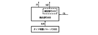
図1~図5を参照すると、一実施形態において、血流測定システム10は、検出部500をさらに含むことができる。検出部500は、受信超音波信号のうちガイド映像プローブ100に受信される映像超音波受信信号IURに基づいて、対象体OBに含まれる血管BPの位置情報PIを検出することができる。例えば、血流測定システム10は、ガイド映像プローブ100に受信される映像超音波受信信号IURを用いて、対象体OB内部の超音波映像UIを提供することができる。この場合、本発明による血流測定システム10に含まれる検出部500は超音波映像UIに基づいて、血管BPの位置情報PIを確認することができる。
Referring to FIG. 1 to FIG. 5, in one embodiment, the blood
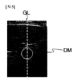
一実施形態において、検出部500は、測定部510をさらに含むことができる。測定部510は、血管BPの位置情報PIおよび超音波映像の深さ方向に形成される横断面ガイドラインGLに沿って、血管BPの横断面の面積に該当する横断面積MZを測定することができる。例えば、ガイドラインGLは、超音波映像UIの中央に血管BPの横断面DMが配置されることができるようにガイドする基準線であることができる。本発明による血流測定システム10に含まれる測定部510は、血管BPの位置情報PIに基づいて、ガイドラインGLに血管BPの横断面DMが配置されることができるように制御することができる。その後、測定部510は、血管BPの横断面DMの面積に該当する横断面積MZを測定することができる。
In one embodiment, the detection unit 500 may further include a measurement unit 510. The measurement unit 510 may measure a cross-sectional area MZ corresponding to the area of the cross-section of the blood vessel BP along the position information PI of the blood vessel BP and a cross-sectional guideline GL formed in the depth direction of the ultrasound image. For example, the guideline GL may be a reference line that guides the cross-section DM of the blood vessel BP to be positioned at the center of the ultrasound image UI. The measurement unit 510 included in the blood
図6は、図1の血流測定システムに含まれる算出部の動作を説明するための図であり、図7および図8は、図1の血流測定システムの制御部に含まれる選択部の動作を説明するための図である。 Figure 6 is a diagram for explaining the operation of a calculation unit included in the blood flow measurement system of Figure 1, and Figures 7 and 8 are diagrams for explaining the operation of a selection unit included in the control unit of the blood flow measurement system of Figure 1.
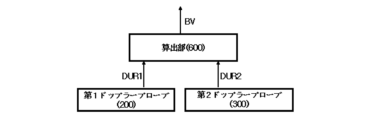
図1~図8を参照すると、血流測定システム10は、算出部600をさらに含むことができる。算出部600は、受信超音波信号のうち第1ドップラープローブ200に受信される第1ドップラー超音波受信信号DUR1および受信超音波信号のうち第2ドップラープローブ300に受信される第2ドップラー超音波受信信号DUR2に基づいて、血流速度を算出することができる。
Referring to FIG. 1 to FIG. 8, the blood
一実施形態において、制御部400は、選択部410をさらに含むことができる。選択部410は、制御信号CSのうち選択信号SEに基づいて、第1ドップラープローブ200および第2ドップラープローブ300を選択的に駆動することができる。例えば、制御信号CSは、選択信号SEを含むことができる。選択信号SEは、第1選択信号SE1および第2選択信号SE2を含むことができる。第1ドップラープローブ200を駆動するために、選択部410は、第1選択信号SE1をターン-オンすることができ、第2ドップラープローブ300を駆動するために、選択部410は、第2選択信号SE2をターン-オンすることができる。
In one embodiment, the
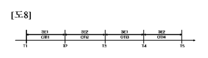
一実施形態において、選択部410は、予め定められた所定の時間間隔に該当する駆動間隔ごとに第1ドップラープローブ200および第2ドップラープローブ300を交互に駆動することができる。例えば、複数の時間は、第1時間T1~第5時間T5を含むことができ、駆動間隔OTIは、第1駆動間隔OTI1~第4駆動間隔OTI4を含むことができる。第1駆動間隔OTI1は、第1時間T1から第2時間T2までの時間間隔であることができ、第2駆動間隔OTI2は、第2時間T2から第3時間T3までの時間間隔であることができる。また、第3駆動間隔OTI3は、第3時間T3から第4時間T4までの時間間隔であることができ、第4駆動間隔OTI4は、第4時間T4から第5時間T5までの時間間隔であることができる。この場合、選択部410は、第1駆動間隔OTI1の間に、第1選択信号SE1をターン-オンして第1ドップラープローブ200を駆動することができ、第2駆動間隔OTI2の間に、第2選択信号SE2をターン-オンして第2ドップラープローブ300を駆動することができる。これと同じ方式で、第3駆動間隔OTI3および第4駆動間隔OTI4でも第1ドップラープローブ200および第2ドップラープローブ300を交互に駆動することができる。
In one embodiment, the
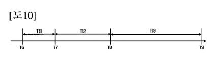
図9は、図1の血流測定システムの動作モードのうち第1動作モードおよび第2動作モードを説明するための図であり、図10は、図9の第1動作モードを説明するための図であり、図11は、図1の血流測定システムが心拍出量を計算する方法を説明するための図である。 Figure 9 is a diagram for explaining the first and second operating modes of the blood flow measurement system of Figure 1, Figure 10 is a diagram for explaining the first operating mode of Figure 9, and Figure 11 is a diagram for explaining the method by which the blood flow measurement system of Figure 1 calculates cardiac output.
図1~図11を参照すると、血流測定システム10は、複数の動作モードで動作することができる。検出部500が血管BPの位置情報PIを検出する場合、複数の動作モードのうち第1動作モードでは、制御部400は、送信超音波信号UTを送信する間隔に該当する送信間隔を順に増加させることができる。例えば、検出部500が血管BPの位置情報PIを正確に検出した後には、対象体OBの内部血管BPの位置を確認するために、検出部500が血管BPの位置情報PIを検出する前より頻繁に送信超音波信号UTを送信する必要をなくすことができる。
Referring to FIG. 1 to FIG. 11, the blood
この場合、制御部400は、送信間隔を順に増加させることができる。例えば、複数の時間は、第6時間T6~第9時間T9を含むことができる。送信間隔は、第1送信間隔TI1~第3送信間隔TI3を含むことができる。第1送信間隔TI1は、第6時間T6から第7時間T7までの時間間隔であることができ、第2送信間隔TI2は、第7時間T7から第8時間T8までの時間間隔であることができる。また、第3送信間隔TI3は、第8時間T8から第9時間T9までの時間間隔であることができる。この場合、第1送信間隔TI1は、第2送信間隔TI2より小さいことができ、第2送信間隔TI2は、第3送信間隔TI3より小さいことができる。このように、検出部500が血管BPの位置情報PIを検出した後には、ガイド映像プローブ100を用いて、超音波映像を実現するための時間間隔を徐々に増加させて、血流測定システム10が他の動作を行うことができるように、システムロードを減少させることができる。
In this case, the
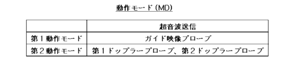
第1動作モードで超音波信号を送信するプローブはガイド映像プローブ100であることができ、第2動作モードで超音波信号を送信するプローブは第1ドップラープローブ200および第2ドップラープローブ300であることができる。
The probe that transmits the ultrasound signal in the first operating mode may be the
一実施形態において、検出部500が血管BPの位置情報PIを検出する場合、複数の動作モードのうち第2動作モードでは、制御部400は第1ドップラープローブ200および第2ドップラープローブ300を駆動して第1ドップラー超音波送信信号および第2ドップラー超音波送信信号を対象体OBに含まれる血管BPに交互に送信することができる。また、一実施形態において、血流測定システム10は、第1ドップラー超音波送信信号が血管BPから反射して第1ドップラープローブ200に受信される第1ドップラー超音波受信信号DUR1および第2ドップラー超音波送信信号が血管BPから反射して第2ドップラープローブ300に受信される第2ドップラー超音波受信信号DUR2に基づいて、血流速度を算出することができる。
In one embodiment, when the detection unit 500 detects the position information PI of the blood vessel BP, in a second operation mode among the plurality of operation modes, the
例えば、検出部500が血管BPの位置情報PIを正確に検出した後、本発明による血流測定システム10は、血管BPの血流速度BVを測定するのにリソースを集中することができる。この場合、第1駆動間隔OTI1の間に、第1選択信号SE1によって駆動される第1ドップラープローブ200を用いて、血管BPに含まれる予め定められた地点に集束して第1ドップラー超音波送信信号を送信し、血管BPから反射して第1ドップラープローブ200に受信される第1ドップラー超音波受信信号DUR1を受信することができる。また、第2駆動間隔OTI2の間に、第2選択信号SE2によって駆動される第2ドップラープローブ300を用いて、血管BPに含まれる予め定められた地点に集束して第2ドップラー超音波送信信号を送信し、血管BPから反射して第2ドップラープローブ300に受信される第2ドップラー超音波受信信号DUR2を受信することができる。本発明による血流測定システム10は、第1ドップラー超音波受信信号DUR1および第2ドップラー超音波受信信号DUR2に基づいて、血流速度BVを算出することができる。
For example, after the detection unit 500 accurately detects the position information PI of the blood vessel BP, the blood
図11に図示されている数学式から分かるように、第1ドップラープローブ200および第2ドップラープローブ300を用いると、入射角に影響を与えることなく、時間による第1血流速度に該当する第1スペクトログラムおよび第2血流速度に該当する第2スペクトログラムを生成することができ、スペクトログラムから速度時間整数(Velocity time integral、VTI)を生成することができる。一実施形態において、本発明による血流測定システム10は、速度時間整数、横断面積MZおよび心拍数に基づいて、心拍出量を算出することもできる。ここで、心拍出量は、速度時間整数、横断面積MZおよび心拍数を乗じた形態で表現されることができる。
As can be seen from the mathematical formula shown in FIG. 11, by using the
Claims (10)
複数の第1ドップラー超音波エレメントを含み、前記第1方向と垂直な方向に該当する第2方向に沿って、前記ガイド映像プローブの一側に配置される第1ドップラープローブと、
複数の第2ドップラー超音波エレメントを含み、前記第1方向と垂直な方向に該当する第3方向に沿って、前記ガイド映像プローブの他側に配置される第2ドップラープローブと、
前記ガイド映像プローブ、前記第1ドップラープローブおよび前記第2ドップラープローブを制御する制御信号を提供する制御部とを含み、
前記制御部が提供する前記制御信号のうち第1制御信号に基づいて、前記ガイド映像プローブが対象体に送信超音波信号を提供した後、前記ガイド映像プローブは、前記対象体から反射する映像超音波受信信号を受信し、前記制御信号のうち第2制御信号に基づいて、前記ガイド映像プローブが前記対象体に前記送信超音波信号を提供した後、前記第1ドップラープローブおよび前記第2ドップラープローブは、前記対象体から反射するドップラー超音波受信信号を受信することを特徴とする、血流測定システム。 a guide imaging probe including a plurality of imaging ultrasound elements and disposed along a first direction;
a first Doppler probe including a plurality of first Doppler ultrasound elements and disposed on one side of the guide image probe along a second direction perpendicular to the first direction;
a second Doppler probe including a plurality of second Doppler ultrasound elements and disposed on the other side of the guide image probe along a third direction perpendicular to the first direction;
a control unit for providing control signals for controlling the guide image probe, the first Doppler probe, and the second Doppler probe ;
and a control signal provided by the control unit to the guide image probe, the guide image probe providing a transmission ultrasound signal to the target body based on a first control signal among the control signals provided by the control unit, and the guide image probe receiving an image ultrasound reception signal reflected from the target body, and a control signal provided by the control unit to the guide image probe providing the transmission ultrasound signal to the target body based on a second control signal among the control signals, and the first Doppler probe and the second Doppler probe receiving a Doppler ultrasound reception signal reflected from the target body .
受信超音波信号のうち前記ガイド映像プローブに受信される映像超音波受信信号に基づいて、対象体に含まれる血管の位置情報を検出する検出部をさらに含むことを特徴とする、請求項1に記載の血流測定システム。 The blood flow measurement system includes:
The blood flow measuring system according to claim 1 , further comprising a detection unit for detecting position information of blood vessels included in a target object based on an imaging ultrasound reception signal received by the guide imaging probe among received ultrasound signals.
前記受信超音波信号のうち前記第1ドップラープローブに受信される第1ドップラー超音波受信信号および前記受信超音波信号のうち前記第2ドップラープローブに受信される第2ドップラー超音波受信信号に基づいて、血流速度を算出する算出部をさらに含むことを特徴とする、請求項3に記載の血流測定システム。 The blood flow measurement system includes:
4. The blood flow measuring system according to claim 3, further comprising a calculation unit that calculates a blood flow velocity based on a first Doppler ultrasonic reception signal received by the first Doppler probe among the received ultrasonic signals and a second Doppler ultrasonic reception signal received by the second Doppler probe among the received ultrasonic signals.
前記検出部が前記血管の位置情報を検出する場合、
前記複数の動作モードのうち第1動作モードでは、前記制御部は、前記送信超音波信号を送信する間隔に該当する送信間隔を順に増加させることを特徴とする、請求項6に記載の血流測定システム。 The blood flow measurement system operates in a number of operating modes;
When the detection unit detects position information of the blood vessel,
The blood flow measuring system according to claim 6 , wherein in a first operation mode among the plurality of operation modes, the control unit sequentially increases a transmission interval corresponding to an interval at which the transmitted ultrasonic signal is transmitted.
前記複数の動作モードのうち第2動作モードでは、前記制御部は、前記第1ドップラープローブおよび前記第2ドップラープローブを駆動して、第1ドップラー超音波送信信号および第2ドップラー超音波送信信号を前記対象体に含まれる前記血管に交互に送信することを特徴とする、請求項7に記載の血流測定システム。 When the detection unit detects position information of the blood vessel,
8. The blood flow measuring system of claim 7, characterized in that in a second operating mode among the plurality of operating modes, the control unit drives the first Doppler probe and the second Doppler probe to alternately transmit a first Doppler ultrasound transmission signal and a second Doppler ultrasound transmission signal to the blood vessel included in the target body.
前記第1ドップラー超音波送信信号が前記血管から反射して第1ドップラープローブに受信される第1ドップラー超音波受信信号および前記第2ドップラー超音波送信信号が前記血管から反射して第2ドップラープローブに受信される第2ドップラー超音波受信信号に基づいて、前記血流速度を算出することを特徴とする、請求項8に記載の血流測定システム。 The blood flow measurement system includes:
9. The blood flow measuring system according to claim 8, wherein the blood flow velocity is calculated based on a first Doppler ultrasonic reception signal obtained by reflecting the first Doppler ultrasonic transmission signal from the blood vessel and receiving it at a first Doppler probe, and a second Doppler ultrasonic reception signal obtained by reflecting the second Doppler ultrasonic transmission signal from the blood vessel and receiving it at a second Doppler probe.
Applications Claiming Priority (3)
| Application Number | Priority Date | Filing Date | Title |
|---|---|---|---|
| KR10-2022-0096511 | 2022-08-03 | ||
| KR1020220096511A KR102470768B1 (en) | 2022-08-03 | 2022-08-03 | Blood flow measurement system |
| PCT/KR2023/000746 WO2024029676A1 (en) | 2022-08-03 | 2023-01-16 | Blood flow measurement system |
Publications (2)
| Publication Number | Publication Date |
|---|---|
| JP2024530556A JP2024530556A (en) | 2024-08-23 |
| JP7621690B2 true JP7621690B2 (en) | 2025-01-27 |
Family
ID=84237296
Family Applications (1)
| Application Number | Title | Priority Date | Filing Date |
|---|---|---|---|
| JP2023563933A Active JP7621690B2 (en) | 2022-08-03 | 2023-01-16 | Blood flow measurement system |
Country Status (6)
| Country | Link |
|---|---|
| US (1) | US12569220B2 (en) |
| EP (1) | EP4566545A1 (en) |
| JP (1) | JP7621690B2 (en) |
| KR (1) | KR102470768B1 (en) |
| CN (1) | CN117835916A (en) |
| WO (1) | WO2024029676A1 (en) |
Families Citing this family (2)
| Publication number | Priority date | Publication date | Assignee | Title |
|---|---|---|---|---|
| KR102470768B1 (en) * | 2022-08-03 | 2022-11-25 | 주식회사 엣지케어 | Blood flow measurement system |
| KR102811568B1 (en) * | 2022-11-25 | 2025-05-26 | (주)알앤에스랩 | Ultrasonic sensor for monitoring blood vessel and control method thereof |
Citations (3)
| Publication number | Priority date | Publication date | Assignee | Title |
|---|---|---|---|---|
| JP2009089911A (en) | 2007-10-09 | 2009-04-30 | Yunekusu:Kk | Vascular ultrasound image measurement method |
| JP2021502840A (en) | 2017-11-14 | 2021-02-04 | コーニンクレッカ フィリップス エヌ ヴェKoninklijke Philips N.V. | Ultrasonic vascular navigation devices, systems, and methods |
| JP2022512027A (en) | 2018-10-22 | 2022-02-01 | コーニンクレッカ フィリップス エヌ ヴェ | Methods and systems for deriving parameters for flow from blood vessels |
Family Cites Families (12)
| Publication number | Priority date | Publication date | Assignee | Title |
|---|---|---|---|---|
| JPS56119237A (en) * | 1980-02-27 | 1981-09-18 | Tokyo Shibaura Electric Co | Urtrasonic diagnosis apparatus |
| JPS59183213U (en) * | 1983-05-25 | 1984-12-06 | アロカ株式会社 | ultrasonic probe |
| US5769079A (en) * | 1996-10-22 | 1998-06-23 | Acuson Corporation | Method and apparatus for determining quantitative measures of flow parameters |
| JP2001198122A (en) * | 2000-01-18 | 2001-07-24 | Toshiba Corp | Two-dimensional array type ultrasonic probe and ultrasonic diagnostic apparatus |
| KR100432617B1 (en) * | 2001-05-16 | 2004-05-22 | 주식회사 메디슨 | Apparatus and method for forming ultrasound images using a set of golay codes with orthogonal property |
| KR101378085B1 (en) * | 2012-06-13 | 2014-03-27 | 삼성전자주식회사 | Method and Apparatus of 3-dimensional volume scanning using 2-dimensional transducer array |
| KR101511221B1 (en) * | 2013-09-04 | 2015-04-10 | 서강대학교산학협력단 | Ultrasound Transducer, Ultrasound Medical Imaging System and 3D Ultrasound Image Generating Method |
| KR102069949B1 (en) * | 2017-10-23 | 2020-01-23 | 서강대학교산학협력단 | Method for reconstructing high quality ultrasound image and ultrasound imaging device thereof |
| KR102285486B1 (en) * | 2019-09-17 | 2021-08-03 | 디지탈에코 주식회사 | Manufacturing method for a flexible ultrasound array transducer |
| CN114554968B (en) * | 2019-10-17 | 2024-08-13 | 韦拉索恩股份有限公司 | System and method for ultrasound scanning |
| KR102381709B1 (en) | 2019-12-20 | 2022-04-01 | 대상 주식회사 | Method of manufacuring dietary fiber |
| KR102470768B1 (en) * | 2022-08-03 | 2022-11-25 | 주식회사 엣지케어 | Blood flow measurement system |
-
2022
- 2022-08-03 KR KR1020220096511A patent/KR102470768B1/en active Active
-
2023
- 2023-01-16 JP JP2023563933A patent/JP7621690B2/en active Active
- 2023-01-16 WO PCT/KR2023/000746 patent/WO2024029676A1/en not_active Ceased
- 2023-01-16 US US18/559,500 patent/US12569220B2/en active Active
- 2023-01-16 EP EP23789474.6A patent/EP4566545A1/en active Pending
- 2023-01-16 CN CN202380011108.8A patent/CN117835916A/en active Pending
Patent Citations (3)
| Publication number | Priority date | Publication date | Assignee | Title |
|---|---|---|---|---|
| JP2009089911A (en) | 2007-10-09 | 2009-04-30 | Yunekusu:Kk | Vascular ultrasound image measurement method |
| JP2021502840A (en) | 2017-11-14 | 2021-02-04 | コーニンクレッカ フィリップス エヌ ヴェKoninklijke Philips N.V. | Ultrasonic vascular navigation devices, systems, and methods |
| JP2022512027A (en) | 2018-10-22 | 2022-02-01 | コーニンクレッカ フィリップス エヌ ヴェ | Methods and systems for deriving parameters for flow from blood vessels |
Also Published As
| Publication number | Publication date |
|---|---|
| US20250099068A1 (en) | 2025-03-27 |
| EP4566545A1 (en) | 2025-06-11 |
| US12569220B2 (en) | 2026-03-10 |
| KR102470768B1 (en) | 2022-11-25 |
| JP2024530556A (en) | 2024-08-23 |
| CN117835916A (en) | 2024-04-05 |
| WO2024029676A1 (en) | 2024-02-08 |
Similar Documents
| Publication | Publication Date | Title |
|---|---|---|
| JP7621690B2 (en) | Blood flow measurement system | |
| US6770034B2 (en) | Ultrasonic diagnostic apparatus | |
| JPH0653117B2 (en) | Ultrasonic blood flow automatic measurement device | |
| EP1079242B1 (en) | Ultrasound diagnostic apparatus | |
| BAKER | Applications of pulsed Doppler techniques | |
| JP4441664B2 (en) | Blood vessel shape measuring device and blood flow measuring device | |
| KR102435554B1 (en) | Blood flow measurement system | |
| JP6714144B2 (en) | System and method for determining cardiac output | |
| KR20080087408A (en) | Doppler Ultrasound Diagnostic System for Ultrasound | |
| JP3668687B2 (en) | Pulse wave velocity measuring device and ultrasonic diagnostic device | |
| JP2008212746A (en) | Ultrasonic diagnostic equipment | |
| JP2001276070A (en) | Ultrasound Doppler diagnostic device | |
| EP1159915A2 (en) | Ultrasonic blood flow rate sensing | |
| JPH03215255A (en) | Ultrasonic diagnostic apparatus | |
| JPH0779971A (en) | Ultrasonic bioinstrument | |
| JPH0741036B2 (en) | Ultrasonic device | |
| TW202008954A (en) | System for pulse wave measurement and alignment guidance method thereof | |
| JPH04108434A (en) | Ultrasonic diagnostic device | |
| JPH0324215B2 (en) | ||
| JPH04208142A (en) | Ultrasonic diagnosis device | |
| JPS61187843A (en) | Ultrasonic diagnostic apparatus | |
| JPS62204731A (en) | Ultrasonic attenuated sound velocity measuring apparatus | |
| JPS6036037A (en) | Ultrasonic blood flow speed measuring method and apparatus | |
| JPH04108435A (en) | Ultrasonic diagnostic device | |
| JPS61279234A (en) | Ultrasonic diagnostic apparatus |
Legal Events
| Date | Code | Title | Description |
|---|---|---|---|
| A621 | Written request for application examination |
Free format text: JAPANESE INTERMEDIATE CODE: A621 Effective date: 20231013 |
|
| A131 | Notification of reasons for refusal |
Free format text: JAPANESE INTERMEDIATE CODE: A131 Effective date: 20241022 |
|
| A521 | Request for written amendment filed |
Free format text: JAPANESE INTERMEDIATE CODE: A523 Effective date: 20241202 |
|
| TRDD | Decision of grant or rejection written | ||
| A01 | Written decision to grant a patent or to grant a registration (utility model) |
Free format text: JAPANESE INTERMEDIATE CODE: A01 Effective date: 20241217 |
|
| A61 | First payment of annual fees (during grant procedure) |
Free format text: JAPANESE INTERMEDIATE CODE: A61 Effective date: 20250107 |
|
| R150 | Certificate of patent or registration of utility model |
Ref document number: 7621690 Country of ref document: JP Free format text: JAPANESE INTERMEDIATE CODE: R150 |