JP7621688B2 - Control System - Google Patents
Control System Download PDFInfo
- Publication number
- JP7621688B2 JP7621688B2 JP2023556224A JP2023556224A JP7621688B2 JP 7621688 B2 JP7621688 B2 JP 7621688B2 JP 2023556224 A JP2023556224 A JP 2023556224A JP 2023556224 A JP2023556224 A JP 2023556224A JP 7621688 B2 JP7621688 B2 JP 7621688B2
- Authority
- JP
- Japan
- Prior art keywords
- teeth
- fluid pressure
- motor
- load
- control system
- Prior art date
- Legal status (The legal status is an assumption and is not a legal conclusion. Google has not performed a legal analysis and makes no representation as to the accuracy of the status listed.)
- Active
Links
Images


Classifications
-
- B—PERFORMING OPERATIONS; TRANSPORTING
- B02—CRUSHING, PULVERISING, OR DISINTEGRATING; PREPARATORY TREATMENT OF GRAIN FOR MILLING
- B02C—CRUSHING, PULVERISING, OR DISINTEGRATING IN GENERAL; MILLING GRAIN
- B02C1/00—Crushing or disintegrating by reciprocating members
- B02C1/02—Jaw crushers or pulverisers
- B02C1/025—Jaw clearance or overload control
-
- H02J7/90—
-
- B—PERFORMING OPERATIONS; TRANSPORTING
- B02—CRUSHING, PULVERISING, OR DISINTEGRATING; PREPARATORY TREATMENT OF GRAIN FOR MILLING
- B02C—CRUSHING, PULVERISING, OR DISINTEGRATING IN GENERAL; MILLING GRAIN
- B02C1/00—Crushing or disintegrating by reciprocating members
- B02C1/02—Jaw crushers or pulverisers
- B02C1/04—Jaw crushers or pulverisers with single-acting jaws
-
- B—PERFORMING OPERATIONS; TRANSPORTING
- B02—CRUSHING, PULVERISING, OR DISINTEGRATING; PREPARATORY TREATMENT OF GRAIN FOR MILLING
- B02C—CRUSHING, PULVERISING, OR DISINTEGRATING IN GENERAL; MILLING GRAIN
- B02C25/00—Control arrangements specially adapted for crushing or disintegrating
-
- H—ELECTRICITY
- H02—GENERATION; CONVERSION OR DISTRIBUTION OF ELECTRIC POWER
- H02J—CIRCUIT ARRANGEMENTS OR SYSTEMS FOR SUPPLYING OR DISTRIBUTING ELECTRIC POWER; SYSTEMS FOR STORING ELECTRIC ENERGY
- H02J1/00—Circuit arrangements for DC mains or DC distribution networks
- H02J1/10—Parallel operation of DC sources
- H02J1/106—Parallel operation of DC sources for load balancing, symmetrisation, or sharing
-
- H—ELECTRICITY
- H02—GENERATION; CONVERSION OR DISTRIBUTION OF ELECTRIC POWER
- H02J—CIRCUIT ARRANGEMENTS OR SYSTEMS FOR SUPPLYING OR DISTRIBUTING ELECTRIC POWER; SYSTEMS FOR STORING ELECTRIC ENERGY
- H02J7/00—Circuit arrangements for charging or depolarising batteries or for supplying loads from batteries
- H02J7/34—Parallel operation in networks using both storage and other DC sources, e.g. providing buffering
-
- H—ELECTRICITY
- H02—GENERATION; CONVERSION OR DISTRIBUTION OF ELECTRIC POWER
- H02P—CONTROL OR REGULATION OF ELECTRIC MOTORS, ELECTRIC GENERATORS OR DYNAMO-ELECTRIC CONVERTERS; CONTROLLING TRANSFORMERS, REACTORS OR CHOKE COILS
- H02P27/00—Arrangements or methods for the control of AC motors characterised by the kind of supply voltage
- H02P27/04—Arrangements or methods for the control of AC motors characterised by the kind of supply voltage using variable-frequency supply voltage, e.g. inverter or converter supply voltage
- H02P27/06—Arrangements or methods for the control of AC motors characterised by the kind of supply voltage using variable-frequency supply voltage, e.g. inverter or converter supply voltage using DC to AC converters or inverters
- H02P27/08—Arrangements or methods for the control of AC motors characterised by the kind of supply voltage using variable-frequency supply voltage, e.g. inverter or converter supply voltage using DC to AC converters or inverters with pulse width modulation
-
- E—FIXED CONSTRUCTIONS
- E02—HYDRAULIC ENGINEERING; FOUNDATIONS; SOIL SHIFTING
- E02F—DREDGING; SOIL-SHIFTING
- E02F3/00—Dredgers; Soil-shifting machines
- E02F3/04—Dredgers; Soil-shifting machines mechanically-driven
- E02F3/28—Dredgers; Soil-shifting machines mechanically-driven with digging tools mounted on a dipper- or bucket-arm, i.e. there is either one arm or a pair of arms, e.g. dippers, buckets
- E02F3/36—Component parts
- E02F3/40—Dippers; Buckets ; Grab devices, e.g. manufacturing processes for buckets, form, geometry or material of buckets
- E02F3/407—Dippers; Buckets ; Grab devices, e.g. manufacturing processes for buckets, form, geometry or material of buckets with ejecting or other unloading device
-
- E—FIXED CONSTRUCTIONS
- E02—HYDRAULIC ENGINEERING; FOUNDATIONS; SOIL SHIFTING
- E02F—DREDGING; SOIL-SHIFTING
- E02F3/00—Dredgers; Soil-shifting machines
- E02F3/04—Dredgers; Soil-shifting machines mechanically-driven
- E02F3/96—Dredgers; Soil-shifting machines mechanically-driven with arrangements for alternate or simultaneous use of different digging elements
- E02F3/965—Dredgers; Soil-shifting machines mechanically-driven with arrangements for alternate or simultaneous use of different digging elements of metal-cutting or concrete-crushing implements
-
- E—FIXED CONSTRUCTIONS
- E02—HYDRAULIC ENGINEERING; FOUNDATIONS; SOIL SHIFTING
- E02F—DREDGING; SOIL-SHIFTING
- E02F9/00—Component parts of dredgers or soil-shifting machines, not restricted to one of the kinds covered by groups E02F3/00 - E02F7/00
- E02F9/20—Drives; Control devices
- E02F9/2058—Electric or electro-mechanical or mechanical control devices of vehicle sub-units
- E02F9/2091—Control of energy storage means for electrical energy, e.g. battery or capacitors
-
- E—FIXED CONSTRUCTIONS
- E02—HYDRAULIC ENGINEERING; FOUNDATIONS; SOIL SHIFTING
- E02F—DREDGING; SOIL-SHIFTING
- E02F9/00—Component parts of dredgers or soil-shifting machines, not restricted to one of the kinds covered by groups E02F3/00 - E02F7/00
- E02F9/20—Drives; Control devices
- E02F9/2058—Electric or electro-mechanical or mechanical control devices of vehicle sub-units
- E02F9/2095—Control of electric, electro-mechanical or mechanical equipment not otherwise provided for, e.g. ventilators, electro-driven fans
-
- H02J2105/40—
-
- H—ELECTRICITY
- H02—GENERATION; CONVERSION OR DISTRIBUTION OF ELECTRIC POWER
- H02P—CONTROL OR REGULATION OF ELECTRIC MOTORS, ELECTRIC GENERATORS OR DYNAMO-ELECTRIC CONVERTERS; CONTROLLING TRANSFORMERS, REACTORS OR CHOKE COILS
- H02P25/00—Arrangements or methods for the control of AC motors characterised by the kind of AC motor or by structural details
- H02P25/02—Arrangements or methods for the control of AC motors characterised by the kind of AC motor or by structural details characterised by the kind of motor
- H02P25/022—Synchronous motors
- H02P25/024—Synchronous motors controlled by supply frequency
Landscapes
- Engineering & Computer Science (AREA)
- Power Engineering (AREA)
- Food Science & Technology (AREA)
- Mechanical Engineering (AREA)
- Charge And Discharge Circuits For Batteries Or The Like (AREA)
- Secondary Cells (AREA)
- Direct Current Feeding And Distribution (AREA)
Description
本発明は、建設機器の駆動を効率的に運用する制御システムに関する。 The present invention relates to a control system for efficiently operating the drive of construction equipment.
例えば、コンクリートや石などを破砕するクラッシャにはジョークラッシャ、コーンクラッシャ、インパクトクラッシャなど用途に応じて様々な種類のクラッシャがあるが、いずれのクラッシャにおいてもモータを駆動させて破砕歯で原料を破砕する動作が行われる。また、クラッシャを用いた破砕システムは、原料となる鉱石、岩石、コンクリートなどを運搬するコンベア、クラッシャに原料を供給するフィーダ、破砕された石を篩い分けするスクリーンなどの機器で構成されており、これらの機器も駆動する際にモータが利用されている。すなわち、例えば上記に示すような破砕システムを含む建設機器全般においてはモータの駆動制御が極めて重要となる。 For example, there are various types of crushers for crushing concrete, stone, etc., such as jaw crushers, cone crushers, and impact crushers, depending on the purpose, but all of these crushers operate by driving a motor to crush the raw materials with crushing teeth. Furthermore, a crushing system using a crusher is made up of equipment such as conveyors that transport the raw materials such as ore, rocks, and concrete, feeders that supply the raw materials to the crusher, and screens that sift the crushed stone, and motors are used to drive these devices as well. In other words, motor drive control is extremely important for construction equipment in general, including the crushing system shown above, for example.
モータの種類にはいくつかあり、ACモータのうち固定子部分に永久磁石を使用したものとしてIPMモータが知られている。IPMモータは回転子に二次電流を流す必要がないため、回転子での損失を抑え省エネルギーで高効率であるという特徴を有する。また、発熱が少ないために放熱面積を小さくすることができ、モータ自体を小型化、軽量化することが可能となっている。一方で、固定子の位置に合わせた回転磁界を発生させる必要があるため、インバータによる厳密な制御が必要となる。 There are several types of motors, and among AC motors, IPM motors are known as those that use permanent magnets in the stator section. Since IPM motors do not need to pass a secondary current through the rotor, they are characterized by reducing losses in the rotor, making them energy-saving and highly efficient. In addition, because they generate less heat, the heat dissipation area can be made smaller, making it possible to make the motor itself smaller and lighter. On the other hand, because it is necessary to generate a rotating magnetic field that matches the position of the stator, strict control by an inverter is required.
上記のような破砕システムに関連し、バッテリ電源と外部の交流電源とを用いたハイブリッドの破砕機に関する技術が特許文献1、2に開示されている。特許文献1に示す技術は、破砕対象物を破砕する場合に駆動する第1駆動部に電力を供給するための第1接続部と、第1駆動部に電力を供給する外部電源に接続するための第2接続部と、所定のタイミングで第1駆動部に電力を供給すると共に、外部電源からの電力を充電するバッテリ電源と、外部電源からの電力供給、並びにバッテリ電源からの電力供給、及びバッテリ電源への充電を制御するインバータ回路とを備えるものである。In relation to the crushing system described above, technologies relating to a hybrid crusher using a battery power source and an external AC power source are disclosed in
特許文献2に示す技術は、自走式の破砕機は、作業場所を移動する場合に駆動する第1駆動部に電力を供給するための第1接続部と、少なくとも前記第1駆動部に電力を供給するバッテリ電源とを備え、建設機械の排気ガス規制がされている領域を通って作業場所を移動する場合に、前記第1駆動部を前記バッテリ電源からの電力のみで駆動するように制御するものである。The technology shown in Patent Document 2 is a self-propelled crusher that includes a first connection section for supplying power to a first drive section that drives the crusher when moving around the work site, and a battery power source that supplies power to at least the first drive section, and when moving around the work site through an area where exhaust gas regulations for construction machinery are in place, the first drive section is controlled so that it is driven only by power from the battery power source.
特許文献1、2に示す技術は、いずれもバッテリ電源からの電力供給によりクラッシャを動作せることを可能としているが、クラッシャが破砕対象物を破砕する場合は破砕対象物の硬さや量により負荷変動が激しく、その影響でバッテリ電源の駆動が不安定となり(負荷変動に引っ張られてバッテリ電圧の変動が激しくなり)、バッテリ電源の劣化を促進してしまうという問題がある。特に、クラッシャを動作させる場合には、破砕部以外にもコンベアや振動モータなど様々な駆動部が同時に動作するため、負荷変動がより大きくなり、上記のような問題が生じやすくなっている。
The technologies shown in
また、特許文献1、2に示す技術は、外部電源からバッテリ電源に充電を行う機能を有しているが、外部電源を発電機や商用電源など容量が異なるものを使用する場合には、それぞれの容量に応じた充電器を容易する必要があり、設備が複雑で高コストになってしまうという課題を有する。
In addition, the technologies shown in
さらに、特許文献1、2に示す技術においてIPMモータを適用することで、省エネルギーで高効率な駆動動作を実現できる可能性があるが、単にモータをIPMモータに置き換えるだけでは、IPMモータの性能を最大限に発揮することができない。特に、急激に変動する負荷に応じた回生エネルギーが発生するような場合には、バッテリ電源を有していないシステムや、バッテリ電源を有しているとしても回生エネルギーを常に吸収できるような領域が確保されるようなバッテリ電源の制御が必要となる。
Furthermore, by applying an IPM motor to the technologies shown in
さらにまた、IPMモータの性能を最大限に活かすためには、IPMモータを制御するインバータの設定を工夫する必要がある。 Furthermore, in order to maximize the performance of the IPM motor, it is necessary to devise settings for the inverter that controls the IPM motor.
本発明は、上記課題を解決するためになされたものであり、二次電池に接続される直流母線の電圧を電源の容量や二次電池の特性に合わせて最適な値に設定し、二次電池の電池電圧を安定化すると共に、IPMモータの性能を最大限に活かしつつ、当該IPMモータを制御するインバータを保護する制御システムを提供することを目的とする。The present invention has been made to solve the above-mentioned problems, and aims to provide a control system that sets the voltage of a DC bus connected to a secondary battery to an optimal value according to the capacity of the power source and the characteristics of the secondary battery, stabilizes the battery voltage of the secondary battery, and protects the inverter that controls the IPM motor while maximizing the performance of the IPM motor.
本発明に係る制御システムは、建設機器を駆動する駆動部と、当該駆動部に接続され、当該駆動部に供給される電力の変換を行うインバータと、前記駆動部を駆動するための電力を交流電源から受け取って直流電力に変換するコンバータと、前記駆動部の駆動状態に応じて前記コンバータで変換された直流電力を充電し、又は前記駆動部の駆動状態に応じて当該駆動部に電力供給する二次電池と、前記二次電池の状態及び前記交流電源の出力容量に基づいて、前記コンバータの変換電圧を設定するPLCとを備えるものである。The control system of the present invention comprises a drive unit that drives construction equipment, an inverter connected to the drive unit and converting the power supplied to the drive unit, a converter that receives power for driving the drive unit from an AC power source and converts it into DC power, a secondary battery that charges the DC power converted by the converter depending on the driving state of the drive unit, or supplies power to the drive unit depending on the driving state of the drive unit, and a PLC that sets the conversion voltage of the converter based on the state of the secondary battery and the output capacity of the AC power source.
このように、本発明に係る制御システムにおいては、建設機器を駆動する駆動部と、当該駆動部に接続され、当該駆動部に供給される電力の変換を行うインバータと、前記駆動部を駆動するための電力を交流電源から受け取って直流電力に変換するコンバータと、前記駆動部の駆動状態に応じて前記コンバータで変換された直流電力を充電し、又は前記駆動部の駆動状態に応じて当該駆動部に電力供給する二次電池と、前記二次電池の状態及び前記交流電源の出力容量に基づいて、前記コンバータの変換電圧を設定するPLCとを備えるため、二次電池の安定電圧の範囲内でコンバータの変換電圧を設定することが可能となり、二次電池を長寿命化することができるという効果を奏する。 Thus, the control system of the present invention comprises a drive unit that drives construction equipment, an inverter connected to the drive unit and converts the power supplied to the drive unit, a converter that receives power for driving the drive unit from an AC power source and converts it into DC power, a secondary battery that charges the DC power converted by the converter depending on the driving state of the drive unit, or supplies power to the drive unit depending on the driving state of the drive unit, and a PLC that sets the conversion voltage of the converter based on the state of the secondary battery and the output capacity of the AC power source, thereby making it possible to set the conversion voltage of the converter within the stable voltage range of the secondary battery, thereby achieving the effect of extending the life of the secondary battery.
また、交流電源の容量に応じて対応する充電器を用意する必要がなく、コンバータの設定値を調整するだけで電源の容量に影響されることなく充電が可能になるという効果を奏する。 In addition, there is no need to prepare a charger that corresponds to the capacity of the AC power source, and charging is possible without being affected by the capacity of the power source by simply adjusting the setting value of the converter.
(本発明の第1の実施形態)
本実施形態に係る制御システムについて、図1ないし図4を用いて説明する。本実施形態に係る制御システムは、建設機器の電源を制御するものであり、特にハイブリット型のクラッシャを含む建設機器の電源制御に関するものである。ハイブリッド型のクラッシャは、発電機や商用電源などの外部電源からの供給電力と、二次電池などのバッテリ電源からの供給電力を駆動エネルギーとするものであり、駆動部の負荷が大きい場合などに外部電源からの電力供給に加えてバッテリ電源からの電力供給で補給を行うものである。逆に駆動部の負荷が小さく外部電源に余裕がある場合には、余剰電力をバッテリ電源に蓄電しておくことでエネルギーを有効活用する。
(First embodiment of the present invention)
The control system according to this embodiment will be described with reference to Figures 1 to 4. The control system according to this embodiment controls the power supply of construction equipment, and in particular relates to power supply control of construction equipment including a hybrid crusher. A hybrid crusher uses power supplied from an external power source such as a generator or commercial power source and power supplied from a battery power source such as a secondary battery as its driving energy, and when the load on the driving unit is large, the power supply from the battery power source is supplemented in addition to the power supply from the external power source. Conversely, when the load on the driving unit is small and there is a surplus in the external power source, the surplus power is stored in the battery power source to make effective use of energy.
図1は、本実施形態に係る制御システムのシステム構成図である。制御システム1は、例えばクラッシャ、コンベヤ、振動モータ、油圧ポンプ、フィーダ、磁選機などにおいて機械的に動作する駆動部11と、各駆動部11にそれぞれ接続して駆動部11に供給される電力の変換及び制御を行うインバータ12と、各駆動部11を駆動するための電力を外部の交流電源19から受け取って直流電力に変換するコンバータ13と、駆動部11の駆動状態が低負荷である場合にコンバータ13で変換された直流電力を充電し、駆動部11の駆動状態が高負荷である場合に当該駆動部11に電力を供給するリチウムイオンバッテリ14と、当該リチウムイオンバッテリ14の状態、及び外部の交流電源の出力容量に基づいて、コンバータ13の変換電圧を設定するPLC15とを備える。1 is a system configuration diagram of a control system according to this embodiment. The
コンバータ13、リチウムイオンバッテリ14及びインバータ12はそれぞれが直流母線16で接続されている。リチウムイオンバッテリ14は、電池モジュールを監視、制御するためのBMS17を有しており、BMS17とPLC15との間で双方向に通信可能に接続されている。また、PLC15はコンバータ13との間及びインバータ12との間でも双方向に通信可能に接続されている。さらに、直流母線16には電圧を計測するための計測部18が設置されており、PLC15が計測部18の計測結果を取り込めるように構成されている。The
外部の交流電源19は商用電源や発電機であり、電力会社との契約内容や発電機の容量に応じて電圧が異なるものである。通常であれば、それらの供給可能な電力に応じて変換器や充電器を設置する必要があるが、本実施形態においては、コンバータ13による電圧制御により電源容量に関係なく多様な交流電源19に対応することが可能となっている。The external
各駆動部11に接続されるインバータ12は、それぞれの駆動部11に供給する電力を直流電力から交流電力に変換したり、駆動状態に応じたフィードバック制御を行う。上記で例示した各駆動部11は、破砕物の硬さや量により負荷変動が非常に大きいものとなるため、それぞれの駆動部11にインバータ12を設置することで各駆動部11の動作を安定させることができる。このような多数のインバータ12が使用されることで高調波の影響が懸念されるが、コンバータ13と外部の交流電源との間に高調波フィルタモジュール20を備えることで高調波の影響を抑える構成となっている。The
リチウムイオンバッテリ14は、駆動部11の負荷が小さいときは外部の交流電源19からの電力をコンバータ13の電圧制御にしたがって充電し、駆動部11の負荷が大きいときは蓄電されている電力を駆動部11に供給してエネルギー不足を補う。BMS17はリチウムイオンバッテリ14の電池モジュールを常時監視、制御しており、各セルの情報はPLC15に送信されている。When the load on the
ここで、上述したように、本実施形態においては破砕物に応じてクラッシャなどの各駆動部11の負荷変動が非常に大きくなると共に、多数のインバータ12のノイズが影響することでBMS17に不具合が生じ、リチウムイオンバッテリ14の電池電圧がばらついてしまい電池の劣化を促進してしまうという問題が生じる。BMS17では、例えば低電圧のときなどにセルバランスを調整する機能などが備わっているが、本実施形態のように駆動部11の負荷変動が非常に大きく、インバータ12のノイズも非常に大きく影響するような環境においては、上記のようなBMS17では対応することが難しくなる。そのため本実施形態においては、後述するように、システム全体の状況を監視することができるPLC15の制御により直流母線16の電圧をリチウムイオンバッテリ14が安定稼働できる適正電圧に設定すると共に、破砕物の破砕状況を確認しながら所定のタイミングでセルバランスの調整をBMS17に指示することが行われる。Here, as described above, in this embodiment, the load fluctuation of each
PLC15は、システム全体を制御する機能を有しており、BMS17からリチウムイオンバッテリ14における各電池モジュールの状態に関する情報を取得する。取得した情報を元にBMS17に対してセルバランスの調整指令を行う。一方で、リチウムイオンバッテリ14の状態に応じて、コンバータ13に対して直流母線16の最適電圧を演算して設定すると共に、出力の上限値を演算して設定する処理を行う。いずれの処理を行う場合であっても、駆動部11に負荷が掛かっていると電圧変動が大きくで正確なバランス調整や最適電圧の演算を行うことができないため、インバータ12から各駆動部11の駆動状態に関する情報を取得しながら上記のような処理を実行する。
The
ここで、PLC15の構成について詳細に説明する。図2は、本実施形態に係る制御システムにおけるPLCの構成を示す機能ブロック図である。PLC15は、外部の交流電源19の容量に関する容量入力情報21や、直流母線16の電圧を測定する計測部18からの計測結果情報等を取得する情報取得部22と、各駆動部11の駆動状態を監視・制御する駆動制御部23と、駆動部11の駆動状態に応じてリチウムイオンバッテリ14に対してバランス調整等の指令を行うバッテリ制御部24と、駆動部11の駆動状態を見ながらリチウムイオンバッテリ14の安定電圧を測定し、その値に応じて直流母線16の電圧を設定するための情報を演算する演算部25とを備える。Here, the configuration of the
PLC15では、システム全体の駆動状態を監視しながらリチウムイオンバッテリ14のセルバランス調整指令を行うと共に、リチウムイオンバッテリ14への充電を行う場合の直流母線16の電圧を制御することで、リチウムイオンバッテリ14への過剰な負担を抑えて長寿命化を図る。The
駆動制御部23は、各駆動部11の駆動状態を監視・制御する処理部であり、各駆動部11に接続するインバータ12からの情報に基づいて、各駆動部11が(電源がONで)負荷状態であるか(電源がONで)無負荷状態であるかを判断する。The
バッテリ制御部24は、リチウムイオンバッテリ14のBMS17に対してセルバランスを調整するための指令となる情報を送信する。クラッシャなどの駆動部11は、上述したように破砕物の硬さや量によって負荷変動が非常に大きくなるため、それに伴い消費される電力も大きく変動する。そして、その影響はリチウムイオンバッテリ14の各セルにも及ぶため、セル間の電圧がアンバランスになる事態が生じやすくなる。The
各セルの電圧がアンバランスになった場合はセルバランスを調整する必要があるが、駆動部11が負荷状態で駆動していると、各セルの電圧変動が非常に激しくなるためセルバランス調整を行うことができない。そのため、バッテリ制御部24は、駆動制御部23から駆動部11が負荷状態であるか無負荷状態であるかの情報を受け取り、無負荷状態である場合にセルバランスの調整指令を行う。また、セルバランスの調整中に駆動部11が負荷状態になるとセルバランス調整を正確に行うことができなくなるため、バッテリ制御部24からの指令により、駆動制御部23が各駆動部11の動作を制限する。具体的には例えば、駆動部11の駆動を(電源ONの)駆動停止状態に制御したり、操作パネルにセルバランス中である旨の警告を表示し、駆動部11の駆動開始操作を行えないようにする。When the voltage of each cell becomes unbalanced, it is necessary to adjust the cell balance, but if the
演算部25は、外部の交流電源19の容量に応じた電圧上限値を演算し、コンバータ13に指令を送る処理を行う。電圧上限値は、交流電源19が出力できる上限値を元に演算部25で算出する値であり、例えば出力容量の90%の値を電圧上限値として算出する。電圧上限値の指令を受けたコンバータ13は、その範囲(電圧上限値を超えない範囲)で電圧制御を行う。すなわち、外部の交流電源19の容量が様々に異なっても、それぞれの容量に合わせた電圧制御を行うことができるため、異なる容量ごとに充電器や変換器などを用意する必要がなくなる。なお、外部の交流電源19の出力容量は、利用者の操作により容量入力情報21として入力される情報であり、その情報を情報取得部22が取得し演算部25が電圧上限値を算出する。The
また、演算部25は、リチウムイオンバッテリ14の電圧変動が最も小さく、安定して稼働できる最適電圧値を求め、直流母線16の電圧をその最適電圧値に制御するようにコンバータ13に指令を送る。In addition, the
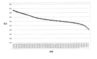
ここで、最適電圧値について説明する。図3は、駆動部11をリチウムイオンバッテリ14の電力で無負荷状態で運転した場合(一定の低負荷状態で運転した場合)の直流母線16の時間経過に対する電圧変動を示すグラフである。このグラフのデータは、駆動制御部23が駆動部11が無負荷状態であると判断し、且つバッテリ制御部24がBMS17から受信した電池電圧が100%である場合に収集されたものである。すなわち、無負荷状態で電池電圧が100%から0%になるまでの時間経過に対する直流母線16の電圧を測定する。なお、グラフに示すデータの収集中は、駆動部11が負荷状態になると直流母船16の電圧変動が大きくなるため、上述した場合と同様に、駆動制御部23からの指令により駆動部11の駆動が制限される。Here, the optimal voltage value will be explained. FIG. 3 is a graph showing the voltage fluctuation over time of the
図3のグラフからわかる通り、このリチウムイオンバッテリ14の場合は310V~330Vで電圧変動が小さくなっており、特に320V付近では時間経過に対して電圧が安定していることがわかる。すなわち、演算部25は、このグラフからリチウムイオンバッテリ14が320V付近の電圧において安定して駆動できるバッテリであると判定することができ、最適電圧値を320Vとする。最適電圧値が求まると、演算部25は、コンバータ13に対してこの最適電圧値を設定する。コンバータ13は、外部の交流電源19からリチウムイオンバッテリ14に充電される際に、直流母線16の電圧が設定された電圧上限値を超えない範囲で最適電圧値となるように変換電圧を制御する。このような制御が行われることで、様々な容量の交流電源を用いた場合であっても、直流母線16の電圧をリチウムイオンバッテリ14が安定的に駆動できる電圧に制御して、リチウムイオンバッテリ14への充電(急速充電)を速やかに行うことができると共に、駆動部11の負荷変動に対しても最適な電圧で一定値を維持しながら、電池の負担を軽減して長寿命化を図ることができる。
As can be seen from the graph in Figure 3, in the case of this lithium-
なお、最適電圧値はリチウムイオンバッテリ14の個体差に応じてそれぞれ測定されてもよいし、同種類(同メーカ)のリチウムイオンバッテリ14であれば一のリチウムイオン電池14の測定値を参考に他のリチウムイオン電池14は固定値として設定してもよい。いずれの場合であっても、リチウムイオン電池14の経年劣化により最適電圧値は変化する。その場合には、定期的に、演算部25の指令により電池残量100%から0%まで無負荷状態で運転を行うように駆動制御部23及びバッテリ制御部24が処理を実行し、新たな測定値が収集される。図4は、リチウムイオンバッテリ14が劣化した場合の図3のグラフ変化を示す図である。図4(A)が劣化前のリチウムイオンバッテリ14で駆動部11を無負荷運転した場合の直流母線16の電圧変化を示すグラフの模式図であり、図4(B)が劣化後の状態を示すグラフの模式図である。図4に示すように、経年劣化によりリチウムイオンバッテリ14が100%から0%まで駆動する場合の駆動時間やそのときの直流母線16の電圧が変化するため(劣化前の最適電圧値X1>劣化後の最適電圧値X2)、演算部25は、新たに収集した測定値に基づいて最適電圧値を再計算し、コンバータ13に対して最適電圧値の更新を行う。The optimum voltage value may be measured according to the individual differences of the
また、上記において電池残量が100%から0%になるまで無負荷運転を行うが、電池が持つ本来の容量に対して、本実施形態においては急速充電が可能で、且つ電圧が比較的安定する20%から80%の範囲で主に使用することが望ましいため、電池本来の容量に対する20%から80%の範囲を0%から100%の範囲に変換して運用することが望ましい。これらの変換は演算部25により行われるようにしてもよい。In the above, no-load operation is performed until the battery remaining capacity drops from 100% to 0%, but in this embodiment, it is desirable to mainly use the battery in the range of 20% to 80%, where rapid charging is possible and the voltage is relatively stable, with respect to the original capacity of the battery. Therefore, it is desirable to convert the range of 20% to 80% of the original capacity of the battery to the range of 0% to 100% for operation. These conversions may be performed by the
このように、本実施形態に係る制御システムにおいては、破砕対象物を破砕するクラッシャを少なくとも有する駆動部11と、当該駆動部11に接続され、当該駆動部11に供給される電力の変換を行うインバータ12と、駆動部11を駆動するための電力を交流電源19から受け取って直流電力に変換するコンバータ13と、駆動部11の駆動状態に応じてコンバータ12で変換された直流電力を充電し、又は駆動部11の駆動状態に応じて当該駆動部11に電力供給する二次電池(例えばリチウムイオンバッテリ14)と、二次電池の状態及び交流電源の出力容量に基づいて、コンバータ12の変換電圧を設定するPLC15とを備えるため、二次電池の安定電圧の範囲内でコンバータ12の変換電圧を設定することが可能となり、二次電池を長寿命化することができる。Thus, the control system of this embodiment comprises a
また、交流電源の容量に応じて対応する充電器を用意する必要がなく、コンバータ12の設定値を調整するだけで電源の容量に影響されることなく充電が可能になる。
In addition, there is no need to prepare a charger that corresponds to the capacity of the AC power source; charging is possible without being affected by the capacity of the power source by simply adjusting the setting value of the
さらに、PLC15は、リチウムイオンバッテリ14が電圧変動しにくい範囲の電圧値にコンバータ12の変換電圧を設定するため、リチウムイオンバッテリ14への負担を抑えて電池の長寿命化を図ることができる。
Furthermore, the
さらにまた、PLC15は、交流電源の出力容量に基づいて、コンバータ12の変換電圧の上限値を演算して設定するため、外部の交流電源である商用電源の契約内容や発電機の容量によらず、様々な外部電源に対して専用の変換器や充電器を用意することなく適用することができる。
Furthermore,
さらにまた、駆動部11の消費電力がコンバータ12の変換電圧の上限値を超える場合に、二次電池から駆動部11に電力が供給されるため、駆動部11の負荷が非常に大きい場合であってもシステムを停止することなく安定して稼働することができる。
Furthermore, when the power consumption of the
さらにまた、PLC15が、駆動部11が無負荷状態である場合に二次電池のモジュール間のバランス制御を行うため、負荷変動が非常に大きい駆動部11を駆動させたり、インバータ12のノイズにより生じる電池モジュール間のアンバランスを定期的に調整することで二次電池への負担を抑えて長寿命化を図ることができる。また、駆動部11が負荷状態である場合は、負荷変動により正確な電圧測定ができず、バランス調整を行うことができないが、駆動部11が無負荷状態である場合にバランス調整を行うため、正確な電圧に基づいて高精度にバランス調整を行うことが可能となる。Furthermore, since the
(本発明の第2の実施形態)
本実施形態に係る制御システムについて、図5ないし図8を用いて説明する。本実施形態に係る制御システムは、前記第1の実施形態の場合と同様に、ハイブリット型のクラッシャによる破砕作業等を行う場合の駆動制御システムについて説明するが、ここでは、建設機器の駆動部をIPMモータで高性能に動作させつつ、当該IPMモータを制御するためのインバータを保護する制御システムについて説明する。なお、本実施形態において前記第1の実施形態と重複する説明は省略する。
Second Embodiment of the Invention
The control system according to this embodiment will be described with reference to Figures 5 to 8. As in the first embodiment, the control system according to this embodiment will be described as a drive control system for performing crushing work using a hybrid crusher, but here, a control system will be described that operates the drive unit of the construction equipment with an IPM motor at high performance while protecting the inverter that controls the IPM motor. Note that descriptions of this embodiment that overlap with those of the first embodiment will be omitted.
図5は、本実施形態に係る制御システムのシステム構成図である。制御システム1は、例えばクラッシャ、コンベヤ、フィーダ、磁選機などの駆動部を動作させるIPMモータ11aと、各IPMモータ11aにそれぞれ接続してIPMモータ11aに供給される電力の変換及び制御を行うインバータ12と、各IPMモータ11aを駆動するための電力を外部の交流電源19から受け取って直流電力に変換するコンバータ13と、IPMモータ11aの駆動状態が低負荷である場合にコンバータ13で変換された直流電力を充電し、IPMモータ11aの駆動状態が高負荷である場合に当該IPMモータ11aに電力を供給するリチウムイオンバッテリ14と、当該リチウムイオンバッテリ14の状態、及び外部の交流電源の出力容量に基づいて、コンバータ13の変換電圧を設定するPLC15とを備える。5 is a system configuration diagram of the control system according to this embodiment. The
図5において、各IPMモータ11aに接続されるインバータ12は、それぞれのIPMモータ11aに供給する電力を直流電力から交流電力に変換したり、駆動状態に応じたフィードバック制御を行う。例えばクラッシャなどの建設機器における各IPMモータ11aは、破砕物の硬さや量により負荷変動が生じるため、IPMモータ11aにインバータ12を設置することで各IPMモータ11aの動作を安定させる。
In Fig. 5, the
また、インバータ12を用いることで一般的な使用状態においてはIPMモータ11aの動作がある程度安定するものの、本実施形態の場合のように負荷変動が急峻で大きい場合には、インバータ12による制御だけではIPMモータ11aの動作を完全に安定することが難しく、そのためにIPMモータ11aの駆動を制限しなければならない場合もあり、IPMモータ11aの性能を最大限に発揮するのが難しいものとなってしまう。具体的には、IPMモータ11aの短時間での停止動作や負荷が急激になくなった場合などに大きい回生エネルギーが発生し、インバータ12がオーバーロードになってエラーになるようなことが起こる。そのため、一般的にはインバータ12がオーバーロードを起こさないようにIPMモータ11aの停止時間を長めに取ったり、IPMモータ11aのトルクや回転数に制限を掛けることでIPMモータ11aやインバータ12を保護する必要がある。つまり、IPMモータ11aが高性能であったとしても、安定制御するためにその性能を制限せざるを得ない状況となる。
Although the use of the
そこで、本実施形態においてはIPMモータ11aへの極めて急峻な負荷変動による回生エネルギーを吸収して当該IPMモータ11aやインバータ12を保護する役割を担うためにリチウムイオンバッテリ14を備える構成となっている。リチウムイオンバッテリ14は通常運転においては、IPMモータ11aの負荷が小さいときは外部の交流電源19からの電力をコンバータ13の電圧制御にしたがって充電し、IPMモータ11aの負荷が大きいときは蓄電されている電力をIPMモータ11aに供給してエネルギー不足を補う。一方でIPMモータ11の負荷が急激になくなったような場合、つまり極めて大きい回生エネルギーが急激に発生した場合には、その回生エネルギーをリチウムイオンバッテリ14が吸収することで、インバータ12のオーバーロード発生を防止する。Therefore, in this embodiment, a lithium-
このとき、リチウムイオンバッテリ14が満充電の状態になっていると発生した回生エネルギーを吸収できない。したがって、図6に示すように、リチウムイオンバッテリ14は、IPMモータ11aに電力を供給するための給電領域とIPMモータ11aからの急激な負荷変動による回生エネルギーを吸収して保護充電領域とを有する状態に制御される。給電領域における充電されている電力は、IPMモータ11aに大きい負荷が掛かった場合にエネルギー不足を補うために利用されると共に、IPMモータ11aの負荷が小さい場合には外部の交流電源19から充電するための領域として利用される。一方で、保護充電領域は、通常運転時には空き状態になっており、IPMモータ11aの負荷が急激に小さくなったりゼロになった場合に発生する急峻な回生エネルギーを吸収する領域として利用される。At this time, if the
上述したように、本実施形態におけるリチウムイオンバッテリ14は、クラッシャなどの建設機器で生じる急激な負荷変動による回生エネルギーを常時十分に吸収できるように制御される必要がある。図5に示すように、リチウムイオンバッテリ14を監視する処理部としてBMS17を備えており、このBMS17はリチウムイオンバッテリ14の電池モジュールを常時監視、制御し、各セルの情報をPLC15に送信する処理を行う。BMS17は、例えば低電圧のときなどにセルバランスを調整する機能などが備わっているが、上述したようにIPMモータ11aの負荷変動が非常に大きく、インバータ12のノイズも非常に大きく影響するような環境においては、BMS17のみでリチウムイオンバッテリ14を常時監視・制御するのは難しい。そのため本実施形態においては、システム全体の状況を監視することができるPLC15からの設定情報に基づいて、コンバータ13が直流母線16の電圧をリチウムイオンバッテリ14が急峻に発生する回生エネルギーを常時吸収することができる電圧に制御する。つまり、コンバータ13を直流母線16の電圧調整手段として機能させる。As described above, the
PLC15は、システム全体を制御する機能を有しており、リチウムイオンバッテリ14の状態に応じて、コンバータ13に対して直流母線16の最適電圧を演算して設定すると共に、出力の上限値を演算して設定する処理を行う。すなわち、給電領域と保護充電領域とを最適に設定し、IPMモータ11aに対して効率よく電力の供給を行いつつ、回生エネルギーが発生した場合にはインバータ12がオーバーロードしないように、回生エネルギーを吸収する領域を確保する。また、リチウムイオンバッテリ14の上限値や下限値が設定されることで結果的にリチウムイオンバッテリ14の長寿命化に繋がる。
The
また、PLC15は、BMS17からリチウムイオンバッテリ14における各電池モジュールの状態に関する情報を取得し、それらの情報を元にBMS17に対してセルバランスの調整指令を行う。この場合、IPMモータ11aに負荷が掛かっていると電圧変動が大きくで正確なバランス調整や最適電圧の演算を行うことができないため、インバータ12から各IPMモータ11aの駆動状態に関する情報を取得しながら上記のような処理を実行する。
The
なお、上述したように、IPMモータ11aによる回生エネルギーがリチウムイオンバッテリ14で吸収されることから、リチウムイオンバッテリ14がインバータ12の保護回路として機能することが可能となっているため、インバータ12によりIPMモータ11aを制御するための電圧値及び/又は周波数を上限値に設定することができる。すなわち、IPMモータ11aの機能が制限されることなく最大限に発揮することができる。As described above, the regenerative energy generated by the IPM motor 11a is absorbed by the
ここで、本実施形態に係る駆動制御システムによりフィーダを制御する場合の処理について具体的に説明する。電気駆動するフィーダ(供給機)は、インバータ12により周波数を制御し、クラッシャへの破砕対象の投入量を調整する。破砕対象が大きい場合や硬い場合にはクラッシャへの負荷が大きくなる。つまり、クラッシャを駆動するIPMモータ11aへの負荷が大きくなる。IPMモータ11aへの負荷が大きくなるとインバータ12の制御によりフィーダを減速、停止させることで破砕対象の供給量を減らし、クラッシャのIPMモータ11aが過負荷にならないようにする。
Here, we will specifically explain the processing when the feeder is controlled by the drive control system according to this embodiment. The electrically driven feeder (supply machine) controls the frequency by the
リチウムイオンバッテリ14を有していない場合や、リチウムイオンバッテリ14を有していても保護充電領域が設定されていない場合は、フィーダの周波数を短時間に下げたり停止させると急峻な回生エネルギーが発生し、インバータ12がオーバーロードになりエラーを起こしてしまう。また、フィーダに原料を投入するとき、フィーダの動力伝達手段としてVベルトを用いる場合は、構造上Vベルトが緩んでしまい瞬間的に過電圧が発生してしまう。原料の投入タイミングを機械や電気的な信号で検出するのは困難であるため、このような過電圧がフィーダを駆動するためのIPMモータ11aのインバータ12で発生してしまうといった現象も生じてしまう。このような問題に対して、図6の構成のように、リチウムイオンバッテリ14に保護充電領域を設定しておくことで、急峻に発生する回生エネルギーを吸収することが可能となるため、極めて短時間での減速、停止がエラーを起こすことなく可能となる。If the
実際にフィーダの駆動を瞬断した場合の結果を図7に示す。図7(A)が従来におけるフィーダの停止時間に対する回転数の変化を示す結果であり、図7(B)が本実施形態におけるフィーダの停止時間に対する回転数の変化を示す結果である。図7から明らかなように、本実施形態の場合はシステム全体が稼働している状態で瞬時にフィーダを停止してもシステム全体の駆動を継続できていることがわかる。すなわち、従来はフィーダを減速、停止するまでに一定の時間が必要であるため、人の判断で早めに制御を行う必要があったが、本実施形態においては、フィーダを瞬時に減速、停止することが可能となったため、稼働効率を上げつつ停止中の無駄な電流発生を抑えることができる。 Figure 7 shows the results when the feeder drive is actually cut off. Figure 7 (A) shows the results of the change in the rotation speed with respect to the stop time of the feeder in the conventional case, and Figure 7 (B) shows the results of the change in the rotation speed with respect to the stop time of the feeder in this embodiment. As is clear from Figure 7, in this embodiment, even if the feeder is stopped instantly while the entire system is operating, the operation of the entire system can be continued. In other words, in the past, it took a certain amount of time to decelerate and stop the feeder, so control had to be performed early by human judgment, but in this embodiment, it is possible to decelerate and stop the feeder instantly, so it is possible to increase the operating efficiency and suppress the generation of unnecessary current during the stop.
また、本実施形態に係る駆動制御システムによりクラッシャを制御する場合の処理について具体的に説明する。従来の電動駆動のクラッシャでは、三相のかご型又は巻き線型のモータを使用して駆動するのが一般的である。実際にクラッシャ(ジョークラッシャ)を駆動した場合の結果を図8に示す。図8(A)が従来の三相モータを用いてクラッシャを駆動した場合のデータであり、図8(B)が本実施形態におけるIPMモータ11aでクラッシャを駆動した場合のデータである。具体的には、図8(B)は、リチウムイオンバッテリ14を備える構成でインバータ12の制御によるIPMモータ11の駆動である。
Next, the process of controlling a crusher using the drive control system according to this embodiment will be specifically described. Conventional electrically driven crushers are generally driven using a three-phase cage-type or wound-type motor. Figure 8 shows the results of actually driving a crusher (jaw crusher). Figure 8 (A) shows data when the crusher is driven using a conventional three-phase motor, and Figure 8 (B) shows data when the crusher is driven by the IPM motor 11a according to this embodiment. Specifically, Figure 8 (B) shows the drive of the
図8のデータからわかるように、本実施形態の場合は従来の三相モータに比べて電流の変動が少なくなり安定性が高く、無負荷電流が約半分(正規化した値で100程度→50程度)になっている。また、負荷時においても従来に比べて低電流(正規化した値で350~600程度→200程度)で破砕を行うことが可能となっている。より具体的には、従来のクラッシャでは90mmのセット値で駆動するのが限界だったが、本実施形態においては60mmのセット値で十分駆動させることが可能となり、従来よりも低い供給電源で極めて効率よく破砕動作を行うことが可能となった。 As can be seen from the data in Figure 8, in the case of this embodiment, there is less current fluctuation and greater stability compared to conventional three-phase motors, and the no-load current is about half (normalized value: from about 100 to about 50). Furthermore, even under load, crushing is possible with a lower current than before (normalized value: from about 350-600 to about 200). More specifically, while conventional crushers were limited to being driven at a set value of 90 mm, this embodiment can be driven sufficiently with a set value of 60 mm, making it possible to perform crushing operations extremely efficiently with a lower supply power than before.
なお、クラッシャを制御する場合には、IPMモータ11aによりフライホイールを駆動し、当該フライホールの動作に合わせて駆動する破砕歯に掛かる負荷変動の回生エネルギーがリチウムイオンバッテリ14に吸収されるようにしてもよい。
When controlling the crusher, the flywheel can be driven by the IPM motor 11a, and the regenerative energy of the load fluctuation applied to the crushing teeth, which are driven in accordance with the operation of the flywheel, can be absorbed by the
このように、本実施形態に係る駆動制御システムにおいては、負荷変動が急激に変動することで生じる回生エネルギーによるインバータ12のオーバーロードなどが生じるのを防止し、インバータ12を保護することができる。また、リチウムイオンバッテリ14が回生エネルギーを吸収することでインバータ12が保護されることから、インバータ12の設定値を広く取ることができ、IPMモータ11aの性能を最大限に活かすことができる。In this way, the drive control system according to this embodiment can prevent the
(本発明の第3の実施形態)
本実施形態に係る制御システムについて、図9ないし図17を用いて説明する。本実施形態においては、建設機器としてジョークラッシャを用いた場合の制御について説明する。なお、本実施形態において前記各実施形態と重複する説明は省略する。
Third embodiment of the present invention
The control system according to this embodiment will be described with reference to Fig. 9 to Fig. 17. In this embodiment, the control will be described when a jaw crusher is used as the construction equipment. Note that in this embodiment, the description that overlaps with each of the above embodiments will be omitted.
従来より、石やコンクリート廃材、アスファルト廃材などを所望の大きさに破砕する破砕装置として、ジョークラッシャが使用されている。ジョークラッシャは、固定された不動歯に対して、スイングジョーに取り付けた動歯を動かし、不動歯と動歯との間に導入した破砕対象物を不動歯と動歯で挟んで破砕するものである。Jaw crushers have traditionally been used as crushing equipment for crushing stones, concrete waste, asphalt waste, etc., to the desired size. Jaw crushers move movable teeth attached to a swing jaw relative to fixed non-movable teeth, and crush the object to be crushed introduced between the movable teeth by clamping it between the movable teeth.
従来のジョークラッシャのうち、多く利用されているシングルトッグル式のジョークラッシャでは、通常、不動歯を固定支持するジョークラッシャの本体フレームに、電動機や油圧モータ等で回転駆動される回転軸が回転可能に軸支され、この回転軸に軸中心をずらして一体化させて設けられる偏心軸部に対し、スイングジョーがその上部を相対回転可能に取り付けられて支持される。Among conventional jaw crushers, the most widely used single toggle type jaw crusher typically has a rotating shaft that is driven by an electric motor or hydraulic motor etc. rotatably supported on the main body frame of the jaw crusher, which fixedly supports the stationary teeth, and an eccentric shaft section is provided integrally with this rotating shaft with its axis shifted, and the upper part of the swing jaw is attached and supported so as to be rotatable relative to the eccentric shaft section.
そして、このスイングジョーの下部が、本体フレームに別途揺動可能として設けられたトッグルプレートの一端部に当接すると共に、トッグルプレートとスイングジョーが互いに離隔せず当接を維持する状態で、スイングジョーがトッグルプレートに対し相対的に揺動可能とされることで、偏心軸部とスイングジョー、トッグルプレート、及び本体フレームが、本体フレームを静止節、偏心軸部を原動節、スイングジョーを従動節とするリンク機構をなし、スイングジョーを不動歯に対して近付けたり離したりする、スイングジョーの揺動を含む所定の動きを繰り返し生じさせられる仕組みである。The lower part of the swing jaw abuts against one end of a toggle plate that is separately provided on the main frame and capable of swinging, and the swing jaw is capable of swinging relative to the toggle plate with the toggle plate and swing jaw maintaining contact without moving away from each other. This allows the eccentric shaft, swing jaw, toggle plate, and main frame to form a link mechanism with the main frame as the stationary joint, the eccentric shaft as the driving joint, and the swing jaw as the driven joint, and this mechanism repeatedly produces a predetermined movement that includes swinging of the swing jaw to move it closer to and away from the stationary teeth.
スイングジョーの下部に当接するトッグルプレートの、スイングジョーに当接する一端部とは反対側の他端部は、本体フレーム上に設けられたトッグルブロック等の受部材により位置決めされている。この受部材(トッグルブロック)を位置調整し、トッグルプレートの本体フレーム上における揺動中心位置を変化させることで、不動歯に対するスイングジョーの相対位置関係を進退調整でき、スイングジョーに取り付けられた動歯と不動歯との間の隙間を、破砕対象物の破砕で得たい破砕片の粒度分布に合わせて調整可能となっている。このような動歯と不動歯との間の隙間を調整可能な従来のジョークラッシャの例として、参考文献1(特開2001-70810号公報)に開示されるものがある。 The other end of the toggle plate, which abuts against the lower part of the swing jaw, opposite the end that abuts against the swing jaw, is positioned by a receiving member such as a toggle block provided on the main frame. By adjusting the position of this receiving member (toggle block) and changing the pivot center position of the toggle plate on the main frame, the relative position of the swing jaw with respect to the stationary teeth can be adjusted forward and backward, and the gap between the moving teeth and the stationary teeth attached to the swing jaw can be adjusted to match the particle size distribution of the crushed pieces to be obtained by crushing the object to be crushed. An example of such a conventional jaw crusher in which the gap between the moving teeth and the stationary teeth can be adjusted is disclosed in Reference 1 (JP Patent Publication 2001-70810).
従来のジョークラッシャは前記参考文献1に例示される構成を有しており、不動歯と動歯との間に金属等の異物を投入された場合、これを破砕できないために過負荷となり、そのまま破砕を継続すると装置の破損等不具合を招くため、過負荷の状態が生じるとこれを判別して装置を停止させる仕組みが導入されていた。
Conventional jaw crushers have the configuration exemplified in
こうした従来のジョークラッシャで、スイングジョーを動かすための回転軸を電動機で駆動するものの場合、負荷が増大すると駆動源である電動機に流れる電流も増大することを利用して、金属等の異物を破砕できない過負荷の状態を電動機の電流値で判定するのが一般的であった。ただし、過負荷の状態を電動機の電流値で判定していたため、過負荷に対応して電動機を停止とする電流の閾値が低く設定されていると、本来破砕されるべき石などの破砕対象物が硬質で割れにくいものである場合などに、ピーク的に高くなる負荷で電動機の電流値が増大して閾値を超える状態となり、過負荷と誤判定して電動機が停止し、破砕が中断する事態が頻発するという課題を有していた。こうした電動機の停止の都度、電動機を再度起動させるために、その起動の支障となる破砕対象物の残りを不動歯と動歯との間から取り出す必要があるなど、復旧に時間がかかり、破砕作業の効率が低下するという問題もあった。In conventional jaw crushers, where the rotating shaft for moving the swing jaws is driven by an electric motor, the current flowing through the motor as the drive source also increases as the load increases. This is the reason why it is common to use the motor's current value to determine whether the crusher is overloaded, in which metals and other foreign objects cannot be crushed. However, because the overload state was determined by the motor's current value, if the current threshold for stopping the motor in response to an overload was set low, the motor's current value would increase at peak loads and exceed the threshold when the object to be crushed, such as stones, is hard and difficult to break. This would result in the motor being erroneously determined to be overloaded, causing the motor to stop and the crushing to be interrupted. Each time the motor was stopped, it was necessary to remove the remaining object from between the stationary and moving teeth in order to restart the motor, which would take a long time to restore and reduce the efficiency of the crushing operation.
これに対し、仮に破砕対象物が硬質の場合に、破砕に係る負荷で電動機の電流値が増大しても過負荷に対応する閾値を超えることがないよう、閾値を高く設定すると、破砕できない異物による負荷上昇に際しても過負荷と判定するタイミングが遅れることで、装置停止までに時間がかかり、装置を過負荷の状態でそのまま暫く作動させることによる不具合、例えば、トッグルプレートの曲がりや軸受の破損など、が発生しやすくなるという課題を有していた。こうして停止が遅れることで損傷や破損等の不具合が生じる箇所は、復旧に時間がかかる装置要部であることが多いため、これも破砕作業の効率を著しく低下させることに繋がった。 On the other hand, if the object to be crushed is hard and the threshold value is set high so that the threshold corresponding to overload is not exceeded even when the current value of the motor increases due to the load related to crushing, the timing of determining that an overload has occurred will be delayed even when the load increases due to foreign objects that cannot be crushed, which will result in a problem that it will take time to stop the device and malfunctions caused by operating the device in an overloaded state for a while, such as bending of the toggle plate and damage to the bearings, are more likely to occur. As a result of this delayed shutdown, the areas where malfunctions such as damage and breakage occur are often key parts of the device that take a long time to restore, which also leads to a significant decrease in the efficiency of the crushing work.
一方、回転軸を油圧モータで駆動するものの場合、負荷の増大が油圧モータを含む油圧回路における油圧の増大としてあらわれることから、負荷の増大に伴う油圧の増大に反応して過負荷を判定し、駆動を停止させる油圧制御機構が採用され、過負荷を迅速に判定して破砕を停止できる仕組みを実現していた。また、油圧による駆動は、その性質上、負荷が電動機の場合のように異常に増大する事態は起こりにくいことに加え、電動機と比較して起動時のトルクを発生させやすく、停止後の起動が迅速に行える、といったメリットがあった。しかし、こうした油圧モータで駆動する装置は、駆動機構が複雑且つ大掛かりなものとなり、装置としてのコストがかかる上、油圧を発生させるために油圧ポンプを常時作動させておく必要があり、ランニングコストも大きくなるという課題を有していた。On the other hand, in the case of devices that drive the rotating shaft with a hydraulic motor, an increase in load appears as an increase in hydraulic pressure in the hydraulic circuit including the hydraulic motor, so a hydraulic control mechanism is adopted that detects an overload in response to an increase in hydraulic pressure accompanying an increase in load, and stops the drive, realizing a mechanism that can quickly detect an overload and stop crushing. In addition, hydraulic drive, by its very nature, is less likely to cause abnormal increases in load as occurs with electric motors, and has the advantage of being easier to generate torque at start-up compared to electric motors, and being able to start up quickly after being stopped. However, devices driven by such hydraulic motors have the problem that the drive mechanism is complex and large-scale, which is costly as a device, and the hydraulic pump needs to be constantly operated to generate hydraulic pressure, resulting in high running costs.
そこで、本実施形態においては、動歯に対する負荷に応じて調整部を制御して、不動歯と動歯の間隔を一時的に大きくすると共に、破砕対象物の破砕や異物の排出に続いて調整部で不動歯と動歯の間隔を元の状態に復帰させて、破砕可能な状態を確保し、破砕対象物を適切に破砕する状態を確実に継続維持できる破砕装置を用いた場合の制御システムについて説明する。 Therefore, in this embodiment, a control system is described for use with a crushing device that controls the adjustment unit in response to the load on the moving teeth to temporarily increase the gap between the fixed teeth and the moving teeth, and then, following crushing of the object to be crushed and discharge of foreign matter, returns the gap between the fixed teeth and the moving teeth to their original state using the adjustment unit, thereby ensuring a state in which crushing is possible and reliably maintaining a state in which the object to be crushed can be appropriately crushed.
本実施形態に係る制御システムで用いられる破砕装置について、図9ないし図15に基づいて説明する。本実施形態では、シングルトッグル式のジョークラッシャである例について説明する。The crushing device used in the control system according to this embodiment will be described with reference to Figures 9 to 15. In this embodiment, an example of a single toggle type jaw crusher will be described.
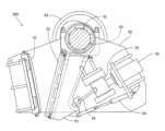
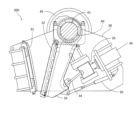
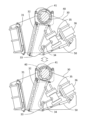
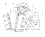
前記各図において本実施形態に係る破砕装置300は、本体フレーム30に固定される不動歯31と、この不動歯31に対向して配置される動歯32と、この動歯32を取り付けられて少なくとも揺動可能に本体フレーム30に配設されるスイングジョー33と、このスイングジョー33の本体フレーム30に対する可動範囲の位置決めを行って、不動歯31と動歯32の間隔を調整可能とする前記調整部としての流体圧シリンダ36と、スイングジョー33及び動歯32を動かす電動機37と、この電動機37と別途にスイングジョー33を動かせる流体圧モータ38と、破砕時における動歯32に対する負荷の変動に対応して、流体圧シリンダ36、電動機37、及び流体圧モータ38を制御する制御部39とを備える。
In each of the above figures, the crushing
この破砕装置300は、固定状態の不動歯31に対して動歯32をスイングジョー33と共に動かして、不動歯31と動歯32との間隔を周期変化させ、不動歯31と動歯32との間に供給、導入される破砕対象物を破砕するものである。This crushing
破砕装置300は、スイングジョー33を動かすための機構として、スイングジョー33の下部に一端部を当接させて設けられるトッグルプレート34と、トッグルプレート34の他端部に当接するようにして本体フレーム30に位置調整可能として設けられるトッグルブロック35とをさらに有する。The crushing
こうした破砕装置各部の機構については、本体フレーム30におけるトッグルブロック35の支持構造と、流体圧シリンダ36を作動させる流体圧回路と、流体圧シリンダ36等を制御する制御部39とを除いて、公知のシングルトッグル式のジョークラッシャと同様のものであり、詳細な説明を省略する。
The mechanisms of each part of this crushing device are the same as those of a known single toggle type jaw crusher, except for the support structure of the
前記不動歯31と動歯32は、それぞれ平板状に形成され、各表面を、複数の突起が波状の横断面をなすように並列する突起面とされる構成である。これら不動歯31が、スイングジョー33に取り付けられる動歯32と対向して配置される状態となる。そして、不動歯31と動歯32との間に、下方が狭く上方が広い破砕用空間が形成される。The fixed
前記本体フレーム30は、例えば金属製の枠組や板組等による剛性の高い立体構造を有するものであり、安定した地面や床面に固定状態で設置される他、自走式台車上に搭載されることもある。この本体フレーム30が、不動歯31と、動歯32を取り付けられたスイングジョー33とを支持することとなる。The
本体フレーム30の上部には、スイングジョー33の支持のための回転軸40が回転可能に軸支される。この回転軸40上に、回転軸の中心から偏心させた偏心軸部41が一体に設けられ、この偏心軸部41周りにスイングジョー33の上端部が相対回転可能に取り付けられる。回転軸40の端部には、公知のジョークラッシャと同様に、フライホイール45と、電動機37からの駆動力を無端ベルトを介して伝えられるプーリ(図示を省略)が取り付けられる。A rotating
前記回転軸40は、通常破砕時は電動機37で回転駆動される。起動時など大きな負荷により電動機に過大な電流が流れうる場合には、流体圧モータ38で回転軸40を駆動し、回転数上昇ののち電動機37による駆動に切り替える仕組みである。The rotating
前記スイングジョー33は、その上部を回転軸40の偏心軸部41に支持される一方、下端部に連結されたテンションロッド50で不動歯31に対し離れる向きに付勢される構成である。The
前記スイングジョー33は、その上部を回転軸40の偏心軸部41に支持される一方、下部の凹部を、本体フレーム30に別途揺動可能として設けられるトッグルプレート34の一端部に当接させ、この当接を維持するように、下端部に連結されたテンションロッド50で不動歯31に対し離れる向きに付勢される構成である。The
前記トッグルプレート34は、金属製の略矩形板状体であり、回転軸40の軸方向(図1の正面方向)と平行な向きとして配設される構成である(図1参照)。このトッグルプレート34の一端部が、スイングジョー33下部の凹部に揺動可能に当接するようにされる。The
前記トッグルブロック35は、本体フレーム30上に、スイングジョー33に対し進退するように、本体フレーム30の一部に移動可能な向きを拘束され、且つ流体圧シリンダ36に連結されて通常は動かない状態として配設される構成である。このトッグルブロック35に設けられた凹部にトッグルプレート34の他端部が揺動可能に当接するようにされる。The
スイングジョー33が不動歯31に対し離れる向きに付勢されることで、スイングジョー33とトッグルブロック35との間にトッグルプレート34が位置して、スイングジョー33とトッグルプレート34の一端部、及び、トッグルブロック35とトッグルプレート34の他端部を、それぞれ当接させ、互いに離隔しない状態が維持される。これにより、スイングジョー33、トッグルプレート34、本体フレーム30、及び回転軸40が一種のリンク機構を構成する。
When the
回転軸40が電動機37や流体圧モータ38の駆動で回転すると、スイングジョー33は、リンク機構の特徴に基づいた、揺動だけではなく上下動なども伴った、不動歯31に対し近付いたり離れたりする所定の動きを繰り返すこととなる。When the
前記流体圧シリンダ36は、前記調整部として、スイングジョー33に対し不動歯31のある側とは反対側となる本体フレーム30の所定箇所に配設され、一端をトッグルブロック35の端部に、他端を本体フレーム30の端部にそれぞれ取り付けられ、これら一端と他端の間隔を流体圧制御で可変とされて、本体フレーム30に対するトッグルブロック35の位置を調整して、これに連動するスイングジョー33及びこれと一体の動歯32を本体フレーム30に対し位置決めし、不動歯31と動歯32の間隔を調整可能とするものである。The
この流体圧シリンダ36は、本体フレーム30におけるスイングジョー33に対し不動歯31の位置する側とは反対側となる部位に、回転軸40の軸方向と平行な向きに並べて複数(例えば、三つ)配設される。
Multiple fluid pressure cylinders 36 (e.g., three) are arranged in a row parallel to the axial direction of the
破砕装置による破砕対象物の破砕で得たい破砕片の粒度に関わる、不動歯31と動歯32との間の隙間の調整は、流体圧シリンダ36でのトッグルブロック35の位置調整によって、トッグルプレート34を介してスイングジョー33及び動歯32を動かし、破砕片の大きさに対応する所定の隙間が得られる位置で、流体圧シリンダ36を静止状態とし、トッグルブロック35を本体フレーム30上で固定状態とする、という手順となる。The gap between the
また、流体圧シリンダ36は、不動歯31と動歯32の間で破砕が滞る異常時、すなわち、破砕中における、破砕可能であるものの破砕しにくい性質の破砕対象物、又は、破砕不能な異物の存在によって、動歯32に対し負荷が増大する際には、制御部39の制御に基づいて、流体圧シリンダ36の一端と他端との間隔を小さくしてトッグルブロック35を不動歯31から離れる向きに動かし、不動歯31と動歯32の間隔を一時的に広げ、破砕対象物の破砕や、異物の不動歯31と動歯32間からの排出を促す仕組みである。In addition, in the event of an abnormality in which crushing is stagnant between the fixed
前記電動機37は、回転軸40から離れた箇所に配設され、無端ベルトを介して回転軸40端部のプーリに駆動力を伝達し、回転軸40を回転駆動して、スイングジョー33及びこれに取り付けられる動歯32を動かすものである。The
前記流体圧モータ38は、本体フレーム30上部に取り付けられ、その出力軸を回転軸40端部のフライホイール45を介して回転軸40に連結され、電動機37と別途に回転軸40を回転駆動して、スイングジョー33及びこれに取り付けられる動歯32を動かすものである。The
この流体圧モータ38は、破砕中に、破砕不能な異物によって動歯32に対し負荷が増大し、破砕が中断すると、制御部39による制御によって回転軸40の正逆回転を小刻みに繰り返すようにされ、この正逆回転でスイングジョー33を動かし、不動歯31と動歯32との間隔を繰り返し変化させることとなる。During crushing, when the load on the moving
前記制御部39は、破砕時における動歯32に対する負荷の変動に対応して、前記調整部としての流体圧シリンダ36や、スイングジョー33と動歯32を動かす電動機37及び流体圧モータ38を制御するものである。The
制御部39は、破砕中に不動歯31と動歯32の間に存在する、破砕可能な破砕対象物又は破砕不能な異物によって、動歯32に対し負荷が増大すると、流体圧シリンダ36の一端と他端との間隔を縮めてスイングジョー33を動かし、不動歯31と動歯32との間隔を広げるようにして負荷を抑える。負荷の増大の原因となった破砕対象物の破砕後、又は、異物の不動歯31と動歯32間からの排出後、流体圧シリンダ36を元の状態に復帰させる。When the load on the moving
詳細には、制御部39は、流体圧制御手段39aと、電動機制御手段39bと、流体圧制御機構部39cとを備えるものである。前記流体圧制御手段39aは、破砕中、破砕可能な破砕対象物によって、動歯32に対し負荷が増大して、スイングジョー33を通じて流体圧シリンダ36の一端と他端との間隔を縮めようとする力が強まり、流体圧シリンダ36に通じる流体圧回路の流体圧が高くなると、流体圧回路で流体圧シリンダの一端と他端との間隔の一時的な縮小を伴うように作動流体を制御して、動歯に対する負荷を抑制可能とするものである。In detail, the
この流体圧制御手段39aは、例えば、流体圧回路における流体圧シリンダ36の縮方向作動に伴って流体圧が増大する側の流路(例えば、複動型片ロッドタイプの流体圧シリンダの場合は、そのキャップ側のシリンダ室に通じる流路)に連通させて設けられるアキュムレータとすることができる。アキュムレータを用いる場合、負荷増大による流体圧シリンダ36に通じる流体圧回路の流体圧の一時的な増大が解消されると、一旦取り込んだ作動流体を流体圧回路の流路に戻して、流体圧シリンダ36を元の状態にそのまま復帰させられることから、スイングジョー33の位置決めに関わる流体圧シリンダ36の一端と他端との間隔についての設定や流体圧シリンダ36の保持圧力の設定を調整せずに済み、こうした調整に係る手間やコストを抑えられる。This fluid pressure control means 39a can be, for example, an accumulator provided in communication with a flow path on the side where the fluid pressure increases with the contraction of the
この他、アキュムレータ同様に、流体圧シリンダ36に通じる流体圧回路の流体圧が増大すると、作動流体の一部を一時的に流体圧回路の流路外に逃がして流体圧シリンダの縮方向作動を許容し、流体圧が低下すると、逃がした作動流体の一部を流体圧回路の流路に速やかに戻せる仕組みであれば、他の制御手段を用いることもできる。In addition, other control means can be used as long as, like an accumulator, when the fluid pressure in the fluid pressure circuit leading to the
前記電動機制御手段39bは、電動機37に流れる電流を検出し、検出した電流値が、不動歯31と動歯32との間に破砕不能な異物が入って動歯に対し過負荷となる状況に対応した、あらかじめ設定された所定の条件(例えば、電流値が過負荷に対応して設定された閾値を超える、など)を満たす場合には、電動機37の駆動を停止させる一方、検出した電流値が前記条件を満たさない場合には、電動機37の駆動を継続させるものである。The motor control means 39b detects the current flowing through the
この他、電動機制御手段39bは、電動機37の駆動を停止させるのに合わせて、破砕装置300の前段に設けられて破砕装置300に破砕対象物を供給するフィーダ(図示を省略)を停止させるようにしてもよい。In addition, the motor control means 39b may stop a feeder (not shown) that is provided upstream of the crushing
このような電動機制御手段39bに対し、流体圧制御手段39aは、破砕可能な破砕対象物によって動歯32に対し過渡的に負荷が増大すると、電動機制御手段39bで検出される電動機37の電流値が前記条件を満たす状態に到らない程度に、作動流体を制御して流体圧シリンダ36の一端と他端との間隔を一時的に縮小させ、負荷を抑えるものとなっている。In contrast to this type of motor control means 39b, when the load on the moving
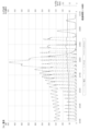
例えば、過負荷の状況に対応した条件として、電動機37に流れる電流値について、300Aを超える状態が0.6秒継続する場合を設定すると、図13に示すように、破砕できない異物が実際に不動歯31と動歯32との間に挟まって動歯32の動きに支障を来す状態となる、運転開始から約327秒経過時以前は、破砕対象物により動歯32に対し過渡的に負荷が増大して流体圧シリンダ36に加わる圧力(トッグル圧)がピーク的に上昇した場合でも、流体圧制御手段39aの作用により流体圧シリンダ36の一端と他端との間隔を一時的に縮小させて、トッグルセットとして示されるトッグルブロック35の不動歯31との位置関係を変化させ、スイングジョー33及び動歯32を不動歯31から離すことで、動歯に対する負荷を抑制し、電動機37の電流値(ジョー電流)が過負荷の状況に対応した前記条件を満たさないようにする仕組みとなっている。For example, if the condition corresponding to an overload situation is set such that the current value flowing through the
前記流体圧制御機構部39cは、流体圧回路の要部をなして、流体圧シリンダ36及び流体圧モータ38の作動を制御するものである。制御部39では、破砕不能な異物によって動歯に対する負荷が増大すると、流体圧シリンダ36で不動歯31と動歯32との間隔を広げるより前に、電動機37による回転軸を通じたスイングジョー33の駆動を停止させると共に、流体圧制御機構部39cにより、流体圧モータ38が回転軸40を正逆回転させてスイングジョー33を動かし、不動歯31と動歯32との間隔を繰り返し変化させるようにしている(図14参照)。The fluid
これにより、不動歯31と動歯32との間で負荷上昇の原因となっている異物を、この不動歯31と動歯32との間から排出されやすくしている。この場合、異物の排出が目的であり、起動時のトルクが重要となる一方、回転軸40を正逆回転させられれば、通常の破砕の場合より低い回転速度でも問題ないことから、流体圧モータ38は破砕に対応する能力を有する必要は無く、流体圧モータ38とこれを作動させるための流体圧回路を小型化することができる。This makes it easier for foreign matter that is causing an increase in load between the fixed
そして、流体圧制御機構部39cは、流体圧モータ38を作動させても、不動歯31と動歯32の間から異物が排出されない場合には、流体圧モータ38を停止させ、流体圧シリンダ36の一端と他端との間隔を縮めてスイングジョー33を動かし、不動歯31と動歯32との間隔を広げる(図15参照)。負荷の増大の原因となった異物の不動歯31と動歯32間からの排出後、流体圧シリンダ36を元の状態に復帰させる。If the
次に、前記構成に基づく破砕装置における、稼働中の過負荷時の対応状態について説明する。前提として、破砕装置300は破砕対象物に対し、電動機37による駆動で無理なくスイングジョー33を動かして、破砕対象物を不動歯31と動歯32との間で支障なく継続的に破砕可能な状態にあるものとする。Next, we will explain how the crushing device based on the above configuration responds to an overload during operation. As a premise, the crushing
また、破砕対象物の破砕を行う前に、あらかじめ不動歯31と動歯32との間の隙間調整が行われるものとする。この隙間調整では、制御部39による制御下で、流体圧シリンダ36を作動させて、トッグルブロック35を本体フレーム30に対し移動させ、これにトッグルプレート34を介して連動するスイングジョー33及びこれと一体の動歯32も移動させることで、不動歯31と動歯32との間の隙間が、得ようとする破砕片の大きさに対応した値となるようにされる。不動歯31と動歯32との間の隙間の大きさが、所望の値となったら、流体圧シリンダ36によるトッグルブロック35の位置調整(移動)が停止し、調整が完了となる。In addition, before crushing the object to be crushed, the gap between the fixed
隙間調整完了後の破砕工程では、破砕装置の破砕に係る作動の開始として、まず流体圧モータ38により回転軸40が回転駆動される。回転軸40が適切な回転数に達すると、電動機37が回転軸40を回転駆動する状態に切り替わり、流体圧モータ38による駆動は停止となる。こうした回転軸40の回転に伴い、スイングジョー33は動歯32と共に不動歯31に対し近付いたり離れたりする所定の動きを繰り返す。In the crushing process after the gap adjustment is completed, the crushing operation of the crushing device is started by first rotating the
破砕を行う破砕装置300の上側には、破砕装置300に破砕対象物を供給するフィーダ(図示を省略)が設けられており、このフィーダにより、破砕対象物を不動歯31と動歯32との間の破砕用空間に供給、導入される。A feeder (not shown) is provided above the crushing
不動歯31と動歯32との間に投入され、不動歯31と動歯32に挟まれた破砕対象物は、スイングジョー33の動きにより、不動歯31と動歯32より挟圧力を受ける。この圧力に伴って破砕対象物の一部に応力が集中し、破砕対象物は応力集中箇所を起点として破砕され分割される。The object to be crushed is inserted between the fixed
不動歯31と動歯32との間の破砕用空間を、破砕対象物が上から下に進行しながら、破砕力を受けて破砕され、粒度を小さくしていく過程が繰り返されて、最終的に、不動歯31と動歯32との間の隙間下端部(排出口)から、所望の大きさの破砕片が排出されることとなる。As the material to be crushed moves from top to bottom through the crushing space between the fixed
こうした破砕装置の稼働中、動いて破砕を行う動歯32に対する負荷は、動歯32をスイングジョー33と共に駆動する回転軸40の回転負荷となり、電動機37に流れる電流値として反映され、この電流値が制御部39の電動機制御手段39bにより監視されている。また、こうした動歯32に対する負荷の増大は、不動歯31と動歯32との間隔を広げようとする見かけの力としてスイングジョー33に作用し、スイングジョー33を後方から支えるトッグルプレート34及びトッグルブロック35を通じて、さらに流体圧シリンダ36を押し縮めようとする力として作用することとなり、流体圧シリンダ36を含む流体圧回路の一部における作動流体の流体圧の増大をもたらす。この流体圧回路における流体圧の増大は、制御部39の流体圧制御手段39aに反映される。During operation of the crushing device, the load on the
そして、この稼働中に、不動歯31と動歯32との間で、破砕可能な破砕対象物がスムーズに破砕されないことや、破砕不能な異物が存在することでの、動歯32に対する負荷の増大が生じると、動歯32及びスイングジョー33の破砕に係る動きが滞ることで、スイングジョー33を適切に動かせない回転軸40の回転負荷の異常に繋がり、これに対応して電動機37の電流値が増大する。また、負荷の増大により、スイングジョー33他を通じて流体圧シリンダ36にこれを押し縮めようとする力が作用して、流体圧回路で流体圧が増大する。During this operation, if a crushable object to be crushed is not crushed smoothly between the fixed
破砕中における、破砕可能な破砕対象物が破砕しにくい性質を有してスムーズに破砕されないことによる、動歯32に対する負荷の過渡的な増大に対しては、制御部39の流体圧制御手段39aが、流体圧シリンダ36に通じる流体圧回路の流体圧が高くなるのに対応して、連通する流体圧回路で、作動流体の一部を一時的に流体圧回路の流路外のスペースに逃がして流体圧シリンダ36の縮方向作動を許容する制御を行い、流体圧シリンダ36の一端と他端との間隔を一時的に縮小させるようにする。During crushing, when a crushable object has difficult-to-crush properties and is not crushed smoothly, there is a transient increase in the load on the moving
こうして流体圧シリンダ36の一端と他端との間隔を一時的に小さくすることで、トッグルブロック35やこれに連動するスイングジョー33を不動歯31から離れる向きに動かし、不動歯31と動歯32の間隔を一時的に広げ(図12参照)、動歯に破砕対象物からの反力として作用する負荷を緩和すると共に、破砕対象物と不動歯31及び動歯32との位置関係を変化させて、破砕対象物の破砕を促すことができる。In this way, by temporarily reducing the distance between one end and the other end of the
破砕されなかった破砕対象物が破砕され、動歯32に対する負荷が減少すると、動歯32及びスイングジョー33の動きに対する破砕対象物からの反力も元の状態に戻ることで、流体圧シリンダ36を設定状態より押し縮めようとする力が前ほど作用せず、流体圧回路で流体圧が減少するのに伴い、流体圧制御手段39aが、逃がした作動流体の一部を流体圧回路の流路に速やかに戻し、流体圧シリンダ36の一端と他端との間隔を元の状態に復帰させる。これに伴い、不動歯31と動歯32の間隔も当初の設定状態に戻ることとなる。When the uncrushed object is crushed and the load on the moving
この場合、流体圧制御手段39aが、動歯32に対する過渡的な負荷の増大に対応して、作動流体を制御して流体圧シリンダ36の一端と他端との間隔を一時的に縮小させ、負荷を抑えることで、電動機制御手段39bで検出される電動機37の電流値は、過負荷に対応した条件を満たす状態には到らず、電動機37が停止することはない。In this case, the fluid pressure control means 39a controls the working fluid to temporarily reduce the distance between one end and the other end of the
一方、破砕中における、不動歯31と動歯32との間に破砕不能な異物が存在することによる、動歯32に対する負荷の増大が生じると、その初期の、制御部39の電動機制御手段39bにおいて検出する電動機37の電流値が、動歯に対し過負荷となる状況に対応する条件を満たさない間は、電動機制御手段39bが電動機37の駆動を継続させる。On the other hand, if an increase in the load on the moving
そして、電動機制御手段39bが、検出した電動機37の電流値が過負荷に対応する前記条件を満たすまでに至ったことを認定した場合には、電動機37の駆動を停止させる。なお、この時、フィーダも停止させて、破砕装置300に破砕対象物が供給されないようにする。
When the motor control means 39b determines that the detected current value of the
また、制御部39の流体圧制御機構部39cは、流体圧モータ38を作動させ、この流体圧モータ38で回転軸40を正逆回転させてスイングジョー33を動かし、不動歯31と動歯32との間隔を繰り返し変化させる(図14参照)。こうして、不動歯31と動歯32との間に留まって過負荷の状態を招いている異物を、この不動歯31と動歯32との間から排出されやすくする。
The fluid
この流体圧モータ38の正逆回転駆動によって異物が不動歯31と動歯32との間から排出された場合には、破砕に係る作動開始時同様に流体圧モータ38を作動させ、次いで電動機37を作動させ、フィーダによる破砕対象物の供給を再開して、破砕作業状態に復帰する。When the foreign object is discharged from between the fixed
流体圧モータ38の正逆回転駆動に伴う動歯32の動きを受けても、異物が不動歯31と動歯32との間から排出されない場合には、制御部39の流体圧制御機構部39cで流体圧回路における流体圧シリンダ36に接続する各流路の流体圧を制御して、流体圧シリンダ36を縮方向に作動させ、流体圧シリンダ36の一端と他端との間隔を小さくする。この場合、破砕可能な破砕対象物がスムーズに破砕されないことで生じた負荷の過渡的な増大の場合より、流体圧シリンダ36の一端と他端との間隔は小さくなるようにされる。
If the foreign object is not discharged from between the
こうして流体圧シリンダ36の一端と他端との間隔を小さくし、トッグルブロック35やこれに連動するスイングジョー33を不動歯31から離れる向きに動かすことで、不動歯31と動歯32との間隔を広げ、不動歯31と動歯32との間から異物をさらに排出しやすい状態とする(図15参照)。異物が不動歯31と動歯32との間の空間下端の排出口から排出されない場合は、あらかじめ流体圧モータ38を停止させてスイングジョー33及び動歯32の動きを止めた状態とした上で、不動歯31と動歯32との間の空間の上側から異物を取り出すようにしてもよい。In this way, the distance between one end and the other end of the
異物が不動歯31と動歯32との間から排出されると、流体圧シリンダ36の一端と他端との間隔を小さくしていた場合は、元の間隔となるよう制御部39の流体圧制御機構部39cで流体圧回路における流体圧シリンダ36に接続する各流路の流体圧を制御して、流体圧シリンダ36を伸方向に作動させ、不動歯31と動歯32との間隔を破砕作業時の設定状態に戻す。その上で、破砕に係る作動の開始時と同様に、流体圧モータ38により回転軸40を駆動し、回転軸40が適切な回転数に達すると、電動機37で回転軸40を回転駆動する状態へ移行させ、回転軸40の回転に伴ってスイングジョー33が動歯32と共に不動歯31に対し近付いたり離れたりする破砕時の作動状態に戻す。そして、フィーダによる破砕対象物の不動歯31と動歯32との間への供給も再開することで、破砕作業状態に復帰する。When the foreign object is discharged from between the fixed
破砕装置300では、制御部39の電動機制御手段39bで破砕中の電動機37の電流値を検出しており、破砕可能な破砕対象物が破砕しにくい性質を有してスムーズに破砕されないことによる、動歯32に対する負荷の過渡的な増大に対しては、制御部39の流体圧制御手段39aが、流体圧シリンダ36の一端と他端との間隔を一時的に縮小させ、負荷を抑えて電動機37を停止させないようにしている。また、破砕不能な異物の存在による、動歯32に対する負荷の増大の場合には、電動機制御手段39bで検出される電動機37の電流値が過負荷に対応する条件を満たす状態になり、電動機制御手段39bが電動機37を停止させることとなる。In the crushing
こうして、主に金属である異物を電動機37の電流値に基づいて精度良く検知して、電動機37の停止で破砕を中断した破砕装置300から回収でき、破砕装置の後段側に金属の異物を流出させずに済むこととなる。仮に破砕装置の次工程に二次破砕装置を用いる場合でも、破砕装置がいわば金属検出器の役割を果たして、金属の異物が二次破砕装置に投入されることを防ぐことができ、二次破砕装置の保護のために破砕装置と二次破砕装置との間に金属検出器を設ける必要がなくなり、破砕に係る工程全体でコストを抑えられる。In this way, foreign objects, mainly metal objects, can be accurately detected based on the current value of the
なお、制御部39は、電動機制御手段39bの検出した電動機37の電流値が過負荷に対応する前記条件を満たす場合、電動機37の駆動を停止させる一方で、流体圧モータ38を新たに作動させ、この流体圧モータ38で回転軸40を正逆回転させてスイングジョー33を動かし、不動歯31と動歯32との間隔を繰り返し変化させるようにしているが、これに限らず、仮に流体圧モータ38による駆動でスイングジョー33及び動歯32を動かしても、異物が不動歯31と動歯32との間から極めて排出されにくい状態にあると、過負荷を認定した当初から予想されるものである場合には、制御部39は流体圧モータ38を作動させず、電動機37の駆動の停止と同時又は停止直後に、流体圧制御機構部39cで流体圧回路における流体圧シリンダ36に接続する各流路の流体圧を制御して、流体圧シリンダ36の一端と他端との間隔を小さくし、スイングジョー33を不動歯31から離れる向きに動かして不動歯31と動歯32との間隔を広げ、不動歯31と動歯32との間から異物を排出しやすい状態とするようにしてもかまわない。In addition, when the current value of the
さらに、電動機制御手段39bで、電動機37の電流値が過負荷に対応する条件を満たす状態を検出し、電動機37の駆動を停止させるのとは別途に、制御部39の流体圧制御機構部39cが、負荷の増大により流体圧シリンダ36に通じる流体圧回路の流体圧が所定の上限値まで増大すると、流体圧を低圧側に逃がす制御を行うことで、流体圧シリンダ36の一端と他端との間隔を小さくし、不動歯31と動歯32との間隔を広げて異物の排出を促すようにすることもできる。この場合、流体圧制御機構部39cの要部として、例えば、流体圧シリンダ36に通じる流体圧回路にリリーフ弁を設けて、流体圧が増大して設定した圧力を超えると、リリーフ弁が作動して流体圧を低圧側に逃がす仕組みとしたり、流体圧回路に所定の流体制御手段を設けて、流体圧が上限値に達した際に、流体圧を低圧側に逃がす制御動作を実行させるものとすることができ、負荷の変化に遅れなく追従して変化する流体圧に基づいて流体圧制御機構部39cで制御を行うことで、破砕中における異物による負荷の増大に対し、不動歯31と動歯32との間隔を自動的に広げるなど、異常状態への有効且つ迅速な対策を講じることができる。Furthermore, in addition to the motor control means 39b detecting a state in which the current value of the
このように、本実施形態に係る破砕装置においては、不動歯31と動歯32との間に入った破砕可能な破砕対象物又は破砕不能な異物によって、破砕に際して動く動歯32への負荷が増大しても、調整部としての流体圧シリンダ36でスイングジョー33を変位させ、不動歯31と動歯32との間隔を広げて、さらなる負荷の増大を抑えると共に破砕対象物の破砕又は異物の排出を行えるようにし、こうした破砕又は排出の完了後、流体圧シリンダ36で不動歯31と動歯32との間隔を元の状態に復帰させ、破砕を継続可能とすることから、破砕可能な破砕対象物の場合は、負荷増大による装置の停止を招かず、且つ動歯32を流体圧シリンダ36の動きで元の状態に速やかに復帰させて、破砕で得られる破砕物を所望の大きさに問題なく維持でき、破砕作業を効率よく且つ精度よく行える。また、破砕不能な異物により負荷が増大して過負荷に至る場合も、流体圧シリンダ36で不動歯31と動歯32との間隔を広げ、異物を排出した後は流体圧シリンダ36で不動歯31と動歯32との間隔を速やかに元に戻すことができ、破砕の中断を必要最小限にして損失を抑えられると共に、未破砕の大きな破砕対象物の流出を防止できる。In this way, in the crushing device of this embodiment, even if the load on the moving
なお、前記実施形態に係る破砕装置において、動歯32に対する負荷の増大が生じても、制御部39の電動機制御手段39bにおいて検出する電動機37の電流値が、動歯32に対し過負荷となる状況に対応する条件を満たさない間は、電動機制御手段39bが電動機37の駆動を継続させるようにし、電流値が過負荷に対応する前記条件を満たして、電動機37の駆動を停止させるまでは、制御部39として流体圧回路側での制御以外は特に制御を行わない構成としているが、これに限られるものではなく、制御部の電動機制御手段が、動歯に対する負荷の上昇が生じた状態における電動機に流れる電流値であって、過負荷の状況に対応した前記条件を満たす場合の電流値より小さい所定の電流値を、第二の閾値としてあらかじめ設定し、電動機制御手段の検出する電動機の電流値がこの第二の閾値を超える場合には、電動機の駆動を継続させる一方で、破砕装置に破砕対象物を供給するフィーダを停止させる構成とすることもできる。In the crushing device according to the above embodiment, even if an increase in the load on the moving
この場合、破砕しにくい破砕対象物や破砕不能な異物により動歯に対する負荷の増大が生じ、電動機制御手段で検出する電動機の電流値が、第二の閾値を超えると、まずフィーダによる破砕装置への破砕対象物の供給が停止される。破砕しにくい破砕対象物の場合で、破砕対象物が破砕され、動歯に対する負荷の減少に基づいて電動機の電流値が第二の閾値を下回ると、フィーダによる破砕対象物の供給が再開される。一方、異物の場合で、破砕できず負荷の増大がさらに進行し、電流値が過負荷に対応する前記条件を満たすと、電動機の駆動が停止される。その後、異物が不動歯と動歯との間から排出され、電動機による回転軸の回転駆動でスイングジョーが動歯と共に不動歯に対し近付いたり離れたりする破砕時の作動状態に戻ると、フィーダによる破砕対象物の不動歯と動歯との間への供給も再開することとなる。In this case, when the load on the moving teeth increases due to objects that are difficult to crush or foreign objects that cannot be crushed, and the current value of the motor detected by the motor control means exceeds the second threshold, the feeder stops supplying the objects to the crushing device. In the case of objects that are difficult to crush, when the objects are crushed and the current value of the motor falls below the second threshold based on the reduction in the load on the moving teeth, the feeder resumes supplying the objects to be crushed. On the other hand, in the case of foreign objects, when the load continues to increase due to failure to crush and the current value meets the above-mentioned condition corresponding to overload, the motor is stopped. After that, the foreign objects are discharged from between the fixed teeth and the moving teeth, and when the operation state during crushing is restored, in which the swing jaw approaches and moves away from the fixed teeth together with the moving teeth due to the rotational drive of the rotating shaft by the motor, the feeder resumes supplying the objects to be crushed between the fixed teeth and the moving teeth.
このように、電動機制御手段で検出される電動機の電流値が、過負荷に対応する条件を満たさないまでも、第二の閾値を超えるようであれば、電動機の駆動は停止させない一方で、フィーダを停止させ、破砕対象物の供給を中断することで、動歯に対する負荷の増大と共に破砕対象物の破砕の進行が滞る中、不動歯と動歯との間にそれ以上破砕対象物を供給しないようにして、負荷が増大する原因となった破砕しにくい破砕対象物の破砕又は異物の排出を集中的に実行でき、後から供給された破砕対象物の影響を受けることなく速やかに破砕又は排出を進められ、負荷の増大した状態をより短時間で解消して破砕作業を継続又は再開できる。In this way, if the motor current value detected by the motor control means exceeds the second threshold value even if it does not satisfy the conditions corresponding to an overload, the drive of the motor is not stopped, but the feeder is stopped and the supply of the objects to be crushed is interrupted. By preventing any further objects to be crushed from being supplied between the fixed and moving teeth while the load on the moving teeth increases and the crushing progress of the objects to be crushed slows, it is possible to concentrate on crushing the difficult-to-crush objects that caused the increase in load or discharging the foreign objects, and crushing or discharging can be carried out quickly without being affected by objects to be crushed that are supplied later, and the increased load condition can be resolved in a shorter time and the crushing operation can be continued or resumed.
この他、フィーダに対しては、電動機制御手段の検出する電動機の電流値に基づいて停止制御を行うのに代えて、トッグルブロックの位置を保持する流体圧シリンダに加わる圧力(トッグル圧)を監視し、破砕しにくい破砕対象物や破砕不能な異物による負荷の増大で流体圧シリンダに加わる圧力が所定の閾値を超えた場合に、フィーダを停止させるよう制御を行う構成とすることもできる。この場合、流体圧回路で負荷増大に応じて明確に圧力の上昇状態が現れることに基づいて、より適切なタイミングでフィーダを停止させることができ、フィーダによる供給を破砕装置の状況に適切に対応させられ、破砕装置で破砕を安全に継続できる。 In addition, instead of controlling the feeder to stop based on the motor current value detected by the motor control means, the pressure (toggle pressure) applied to the fluid pressure cylinder that holds the position of the toggle block can be monitored, and the feeder can be controlled to stop when the pressure applied to the fluid pressure cylinder exceeds a predetermined threshold due to an increase in load caused by objects that are difficult to crush or foreign objects that cannot be crushed. In this case, the feeder can be stopped at a more appropriate time based on the clear appearance of a pressure rise in the fluid pressure circuit in response to an increase in load, and the supply by the feeder can be appropriately adapted to the condition of the crushing device, allowing the crushing device to safely continue crushing.
図16は、上記破砕装置300を用いた場合の制御システム1のシステム構成図である。図16において、駆動部11におけるクラッシャーの具体例としてジョークラッシャー111及びインパクトクラッシャー112を有するシステム構成となっている。図11に示すように、破砕装置300としてのジョークラッシャー111及びインパクトクラッシャー112の駆動部11は、電動機制御手段39bであるインバータ12により制御される電動機37と、油圧モータ38、シリンダ36及び油圧制御部39aを制御する流体圧制御機構部39cとを備える構成となっている。
Figure 16 is a system configuration diagram of the
また、ジョークラッシャー111及びインパクトクラッシャー112の制御システム1における動作は動作制御部150により制御されており、特に電動機37については前述した通りPLC15から制御信号に基づいてインバータ12により行われ、油圧系統の制御については油圧制御部15aの制御に基づいて流体圧制御機構部39cが動作することで行われる。
In addition, the operation of the
なお、図16のように、ジョークラッシャー111及びインパクトクラッシャー112等の破砕装置300は、動作制御部150(PLC15及び/又は油圧制御部15a)によりシステム全体で制御されてもよいし、図11に示すように、それぞれの装置単体で制御するための電動機制御手段39b及び流体圧制御機構部39cを別途備える構成であってもよい。As shown in FIG. 16, the crushing
本実施形態に係る制御システム1を用いた制御方法について具体例を用いて説明する。図17は、本実施形態に係る制御システムを用いた制御方法を示す図である。図17において、破砕対象となる石やコンクリート廃材、アスファルト廃材などが供給機(図示しない)からジョークラッシャー111に投入され、ある程度のサイズになった材料が金属検出器113を通ってインパクトクラッシャー112に投入される。インパクトクラッシャー112で所望のサイズに破砕された材料は、スクリーン114を通って製品として収集される。所望のサイズを満たさずスクリーン114を通らない材料は、再度ジョークラッシャー111又はインパクトクラッシャー112に返送されて、破砕作業が繰り返して実行される。ジョークラッシャー111は、上記で説明したように負荷に応じて不動歯31と動歯32との隙間を調整する調整手段を有している。同様にインパクトクラッシャー112も破砕物を通すための隙間(セット値)を調整する手段を有するようにしてもよい。ジョークラッシャー111では、上記のように金属などの破砕困難な異物が混入された場合にセット値を調整することで、不動歯31と動歯32との隙間を大きくして金属などの異物を排出することができる。排出された金属などの異物は金属検出器113で検知されるため、当該金属検出器113の反応に応じてインパクトクラッシャー112においてセット値を最大値に制御する。そうすることで、金属などの異物がインパクトクラッシャー112のローター、打撃子、反発板等に衝突することを回避して通過させることができ、内部部品の破損を防止することができる。A control method using the
また、図17に示すシステム全体を最適化するように制御することも可能である。具体的には、リターンコンベアや各クラッシャーの負荷値に応じて各クラッシャーのセット値、回転速度等を最適値に制御する。すなわち、例えばジョークラッシャー111の負荷は小さく、インパクトクラッシャー112の負荷が大きくなっているような場合は、ジョークラッシャー111の回転数やセット値を調整して、より細かい破砕を実現することでインパクトクラッシャ112への負荷を抑えつつ、インパクトクラッシャ112では今よりも負荷が小さくなるため、回転数を下げたりセット値を大きくするといった調整を行う。また、例えばスクリーン114から返送される破砕物が多い場合は、各クラッシャーのモーターの回転数を上げることで、より細かい破砕物を生成するように調整する。これ以外にも、例えば生成される破砕物が少ない場合は全体的に負荷を上げたり、生成される破砕物のサイズが大き過ぎたり小さ過ぎる場合は、各クラッシャーのセット値を変更するといった調整を行う。このように、各クラッシャーごとの制御に加えてシステム全体で最適化することで、安定した質や量の破砕物を生成することが可能となる。
It is also possible to control the system shown in FIG. 17 so as to optimize it as a whole. Specifically, the set value, rotation speed, etc. of each crusher are controlled to an optimal value according to the load value of the return conveyor and each crusher. That is, for example, when the load of the
1 制御システム
11 駆動部
11a IPMモータ
12 インバータ
13 コンバータ
14 リチウムイオンバッテリ
15 PLC
15a 油圧制御部
16 直流母線
17 BMS
18 計測部
19 交流電源
20 高調波フィルタモジュール
21 容量入力情報
22 情報取得部
23 駆動制御部
24 バッテリ制御部
25 演算部
30 本体フレーム
31 不動歯
32 動歯
33 スイングジョー
34 トッグルプレート
35 トッグルブロック
36 流体圧シリンダ
37 電動機
38 流体圧モータ
39 制御部
39a 流体圧制御手段
39b 電動機制御手段
39c 流体圧制御機構部
40 回転軸
41 偏心軸部
45 フライホイール
50 テンションロッド
150 動作制御部
300 破砕装置
15a
18 Measuring
Claims (13)
当該駆動部に接続され、当該駆動部に供給される電力の変換を行うインバータと、
前記駆動部を駆動するための電力を交流電源から受け取って直流電力に変換するコンバータと、
前記駆動部の駆動状態に応じて前記コンバータで変換された直流電力を充電し、又は前記駆動部の駆動状態に応じて当該駆動部に電力供給する二次電池と、
前記二次電池の状態及び前記交流電源の出力容量に基づいて、前記コンバータの変換電圧を設定するPLCとを備え、
前記二次電池がリチウムイオン電池であり、前記PLCは、前記リチウムイオン電池が電圧変動しにくい範囲の電圧値に前記コンバータの変換電圧を設定することを特徴とする制御システム。 A drive unit that drives the construction equipment;
an inverter connected to the drive unit and converting power supplied to the drive unit;
a converter that receives power for driving the drive unit from an AC power source and converts the power into DC power;
a secondary battery that is charged with the DC power converted by the converter in accordance with a driving state of the drive unit, or that supplies power to the drive unit in accordance with a driving state of the drive unit;
a PLC that sets a conversion voltage of the converter based on a state of the secondary battery and an output capacity of the AC power source ,
A control system characterized in that the secondary battery is a lithium ion battery, and the PLC sets the conversion voltage of the converter to a voltage value within a range in which the lithium ion battery is less likely to fluctuate in voltage .
当該駆動部に接続され、当該駆動部に供給される電力の変換を行うインバータと、
前記駆動部を駆動するための電力を交流電源から受け取って直流電力に変換するコンバータと、
前記駆動部の駆動状態に応じて前記コンバータで変換された直流電力を充電し、又は前記駆動部の駆動状態に応じて当該駆動部に電力供給する二次電池と、
前記二次電池の状態及び前記交流電源の出力容量に基づいて、前記コンバータの変換電圧を設定するPLCとを備え、
前記PLCは、前記交流電源の出力容量に基づいて、前記コンバータの変換電圧の上限値を演算して設定することを特徴とする制御システム。 A drive unit that drives the construction equipment;
an inverter connected to the drive unit and converting power supplied to the drive unit;
a converter that receives power for driving the drive unit from an AC power source and converts the power into DC power;
a secondary battery that is charged with the DC power converted by the converter in accordance with a driving state of the drive unit, or that supplies power to the drive unit in accordance with a driving state of the drive unit;
a PLC that sets a conversion voltage of the converter based on a state of the secondary battery and an output capacity of the AC power source,
The control system according to claim 1, wherein the PLC calculates and sets an upper limit of the conversion voltage of the converter based on an output capacity of the AC power source .
前記駆動部の消費電力が前記コンバータの変換電圧の上限値を超える場合に、前記二次電池から前記駆動部に電力が供給される制御システム。 3. The control system of claim 2 ,
A control system in which power is supplied to the drive unit from the secondary battery when the power consumption of the drive unit exceeds an upper limit of the conversion voltage of the converter .
前記PLCが、前記駆動部が無負荷状態である場合に前記二次電池のモジュール間のバランス制御を行う制御システム。 3. The control system according to claim 1 ,
The control system includes a PLC that performs balance control between the secondary battery modules when the drive unit is in an unloaded state .
前記建設機器への急激な負荷変動に応じて当該建設機器の駆動部を駆動させるIPMモータを備え、
前記二次電池は、前記インバータに直流母線で接続し、前記駆動部に電力を供給するための給電領域と前記駆動部からの急激な負荷変動による回生エネルギーを吸収して前記インバータを保護する保護充電領域とを有することを特徴とする制御システム。 3. The control system according to claim 1,
an IPM motor that drives a drive unit of the construction equipment in response to a sudden load change on the construction equipment;
A control system characterized in that the secondary battery is connected to the inverter via a DC bus and has a power supply area for supplying power to the drive unit and a protective charging area for absorbing regenerative energy caused by sudden load fluctuations from the drive unit to protect the inverter .
前記二次電池の前記給電領域と前記保護充電領域とを前記直流母線の電圧値で調整する電圧調整手段を備える制御システム。 6. The control system of claim 5 ,
a control system comprising a voltage adjusting means for adjusting the power supply region and the protective charging region of the secondary battery by the voltage value of the DC bus ;
前記インバータが前記IPMモータを制御するための周波数及び/又は電圧値の設定が上限値に調整されている制御システム。 6. The control system of claim 5 ,
A control system in which the setting of a frequency and/or voltage value for the inverter to control the IPM motor is adjusted to an upper limit value .
前記IPMモータが駆動する駆動部がクラッシャーのフライホイールであり、当該フライホイールの動作に合わせて駆動する破砕歯に掛かる負荷変動の回生エネルギーが前記二次電池に吸収される制御システム。 6. The control system of claim 5 ,
The drive unit driven by the IPM motor is a crusher flywheel, and the regenerative energy of the load fluctuation applied to the crushing teeth, which are driven in accordance with the operation of the flywheel, is absorbed by the secondary battery .
前記建設機器が、本体フレームに固定される不動歯と、当該不動歯に対向して配置される動歯と、当該動歯を取り付けられて少なくとも揺動可能に本体フレームに配設されるスイングジョーとを備え、不動歯に対して動歯をスイングジョーと共に動かして、不動歯と動歯との間に入れた破砕対象物を破砕する、ジョークラッシャである破砕装置を含み、
当該破砕装置が、
前記スイングジョーの本体フレームに対する可動範囲の位置決めを行って、前記不動歯と動歯の間隔を調整可能とする調整部と、
破砕時における動歯に対する負荷の変動に対応して、少なくとも前記調整部を制御する制御部とを備え、
破砕可能な破砕対象物又は破砕不能な異物によって、動歯に対し負荷が増大すると、前記制御部が、少なくとも前記調整部で不動歯と動歯との間隔を広げるようにし、負荷の増大の原因となった破砕対象物の破砕後、又は、異物の不動歯と動歯間からの排出後、調整部を元の状態に復帰させることを特徴とする制御システム。 3. The control system according to claim 1 ,
The construction equipment includes a crushing device which is a jaw crusher having a stationary tooth fixed to a main body frame, a movable tooth arranged opposite the stationary tooth, and a swing jaw attached to the movable tooth and at least swingably disposed on the main body frame, and which moves the movable tooth together with the swing jaw relative to the stationary tooth to crush an object to be crushed placed between the stationary tooth and the movable tooth,
The crushing device,
an adjustment unit that adjusts the distance between the fixed teeth and the movable teeth by positioning the movable range of the swing jaw relative to the main body frame;
A control unit that controls at least the adjustment unit in response to a change in load on the movable teeth during crushing,
A control system characterized in that, when the load on the moving teeth increases due to a crushable object to be crushed or an uncrushable foreign object, the control unit widens the space between the fixed teeth and the moving teeth at least in the adjustment unit, and returns the adjustment unit to its original state after the object to be crushed that caused the increase in load is crushed or after the foreign object is expelled from between the fixed teeth and the moving teeth .
前記スイングジョー及び動歯を動かす電動機と、
当該電動機と別途にスイングジョーを動かせる流体圧モータとを備え、
前記制御部が、破砕不能な異物によって、動歯に対し負荷が増大すると、前記調整部で不動歯と動歯との間隔を広げるより前に、電動機による駆動を停止させると共に、流体圧モータを正逆回転駆動させて前記スイングジョーを動かし、不動歯と動歯との間隔を繰り返し変化させ、負荷上昇の原因となった異物が不動歯と動歯との間から排出されやすくすることを特徴とする制御システム。 10. The control system of claim 9 ,
An electric motor for moving the swing jaw and the moving teeth;
The electric motor and a fluid pressure motor for moving the swing jaw separately are provided,
A control system characterized in that, when the load on the moving teeth increases due to an uncrushable foreign object, the control unit stops driving the electric motor before the adjustment unit widens the gap between the fixed teeth and the moving teeth, and drives the fluid pressure motor in forward and reverse directions to move the swing jaw, thereby repeatedly changing the gap between the fixed teeth and the moving teeth, making it easier for the foreign object causing the increase in load to be expelled from between the fixed teeth and the moving teeth .
前記調整部が、前記スイングジョーに対し前記不動歯のある側とは反対側となる所定箇所に配設される流体圧シリンダとされ、当該流体圧シリンダの一端と他端との間隔を変えて前記スイングジョーを位置決めし、前記不動歯と動歯の間隔を調整可能とされ、
前記制御部が、動歯に対し負荷が増大すると、前記調整部としての流体圧シリンダの一端と他端との間隔を縮小させて前記スイングジョーを動かし、不動歯と動歯との間隔を広げるようにし、負荷の増大の原因となった破砕対象物の破砕後、又は、異物の不動歯と動歯間からの排出後、流体圧シリンダを元の状態に復帰させることを特徴とする制御システム。 10. The control system of claim 9 ,
the adjustment unit is a fluid pressure cylinder disposed at a predetermined location on the opposite side of the swing jaw from the side where the fixed teeth are located, and the swing jaw is positioned by changing the distance between one end and the other end of the fluid pressure cylinder, thereby making it possible to adjust the distance between the fixed teeth and the movable teeth,
A control system characterized in that, when the load on the moving teeth increases, the control unit reduces the distance between one end and the other end of the fluid pressure cylinder serving as the adjustment unit, moves the swing jaw, and widens the distance between the fixed teeth and the moving teeth, and returns the fluid pressure cylinder to its original state after the object to be crushed that caused the increase in load has been crushed, or after a foreign object has been expelled from between the fixed teeth and the moving teeth .
前記制御部が、
動歯に対し負荷が増大して、スイングジョーを通じて前記流体圧シリンダの一端と他端との間隔を縮小しようとする力が強まり、流体圧シリンダに通じる流体圧回路の流体圧が高くなると、流体圧シリンダの一端と他端との間隔の一時的な縮小を伴いつつ流体を制御して、動歯に対する負荷を抑制可能とする流体圧制御手段と、
前記電動機に流れる電流を検出し、検出した電流値が、不動歯と動歯との間に破砕不能な異物が入って動歯に対し過負荷となる状況に対応した、あらかじめ設定された所定の条件を満たす場合には、電動機の駆動を停止させる一方、検出した電流値が前記条件を満たさない場合には、電動機の駆動を継続させる電動機制御手段とを備え、
前記流体圧制御手段が、破砕可能な破砕対象物によって動歯に対し過渡的に負荷が増大すると、前記電動機制御手段で検出される電動機の電流値が前記条件を満たす状態に到らない程度に、流体圧シリンダに通じる流体圧回路の流体を制御して流体圧シリンダの一端と他端との間隔を一時的に縮小させることを特徴とする制御システム。 12. The control system of claim 11 ,
The control unit:
a fluid pressure control means for controlling the fluid while temporarily reducing the distance between one end and the other end of the fluid pressure cylinder when the load on the moving teeth increases, and a force that tries to reduce the distance between one end and the other end of the fluid pressure cylinder through the swing jaw becomes stronger and the fluid pressure in the fluid pressure circuit leading to the fluid pressure cylinder becomes high, thereby suppressing the load on the moving teeth;
a motor control means for detecting a current flowing through the motor, and stopping the operation of the motor when the detected current value satisfies a predetermined condition set in advance, which corresponds to a situation where an uncrushable foreign object gets between the stationary teeth and the moving teeth and causes an overload on the moving teeth, and for continuing the operation of the motor when the detected current value does not satisfy the condition;
A control system characterized in that, when the load on the moving teeth increases transiently due to a crushable object to be crushed, the fluid pressure control means controls the fluid in the fluid pressure circuit leading to the fluid pressure cylinder to such an extent that the current value of the motor detected by the motor control means does not reach a state satisfying the condition .
前記制御部の電動機制御手段が、動歯に対する負荷の上昇が生じた状態における電動機に流れる電流値であって、過負荷の状況に対応した前記条件を満たす場合の電流値より小さい所定の電流値を、第二の閾値としてあらかじめ設定し、
前記電動機制御手段が、電動機に流れる電流を検出し、検出した電流値が前記条件を満たさない場合で、且つ前記第二の閾値を超える場合には、電動機の駆動を継続させつつ、破砕装置に破砕対象物を供給するフィーダを停止させることを特徴とする制御システム。
10. The control system of claim 9 ,
The motor control means of the control unit presets a second threshold value, which is a current value flowing through the motor when an increase in the load on the moving teeth occurs, and is smaller than the current value when the condition corresponding to an overload state is satisfied,
The control system is characterized in that the motor control means detects the current flowing through the motor, and if the detected current value does not satisfy the condition and exceeds the second threshold value, continues driving the motor while stopping the feeder that supplies the material to be crushed to the crushing device .
Applications Claiming Priority (5)
| Application Number | Priority Date | Filing Date | Title |
|---|---|---|---|
| JP2021175560 | 2021-10-27 | ||
| JP2021175560 | 2021-10-27 | ||
| JP2022031212 | 2022-03-01 | ||
| JP2022031212 | 2022-03-01 | ||
| PCT/JP2022/036191 WO2023074238A1 (en) | 2021-10-27 | 2022-09-28 | Control system |
Publications (2)
| Publication Number | Publication Date |
|---|---|
| JPWO2023074238A1 JPWO2023074238A1 (en) | 2023-05-04 |
| JP7621688B2 true JP7621688B2 (en) | 2025-01-27 |
Family
ID=86159803
Family Applications (1)
| Application Number | Title | Priority Date | Filing Date |
|---|---|---|---|
| JP2023556224A Active JP7621688B2 (en) | 2021-10-27 | 2022-09-28 | Control System |
Country Status (6)
| Country | Link |
|---|---|
| US (1) | US20240226905A1 (en) |
| EP (1) | EP4425735A4 (en) |
| JP (1) | JP7621688B2 (en) |
| CA (1) | CA3223176A1 (en) |
| MX (1) | MX2023015171A (en) |
| WO (1) | WO2023074238A1 (en) |
Families Citing this family (4)
| Publication number | Priority date | Publication date | Assignee | Title |
|---|---|---|---|---|
| WO2025176933A1 (en) * | 2024-02-22 | 2025-08-28 | Metso Finland Oy | Method of operating a mineral material processing plant with braking energy recovery |
| CN118218104A (en) * | 2024-05-20 | 2024-06-21 | 哈尔滨和泰电力设备有限公司 | Grate cleaning crusher and control method |
| CN118925907A (en) * | 2024-09-23 | 2024-11-12 | 包头市昶泰矿业有限责任公司 | Automatic feeding system of crusher based on PLC control |
| CN120539820B (en) * | 2025-06-16 | 2026-02-13 | 山东山矿机械有限公司 | Method and system for detecting iron passing amount of hydraulic jaw crusher |
Citations (4)
| Publication number | Priority date | Publication date | Assignee | Title |
|---|---|---|---|---|
| JP2002330554A (en) | 2001-04-27 | 2002-11-15 | Kobelco Contstruction Machinery Ltd | Power control device for hybrid vehicle and hybrid construction machine equipped with the power control device |
| JP2009011021A (en) | 2007-06-26 | 2009-01-15 | Sumitomo Heavy Industries Engineering-Service Co Ltd | Hybrid power supply device |
| JP2009284717A (en) | 2008-05-26 | 2009-12-03 | Mazda Motor Corp | Battery control method for vehicle and its device |
| WO2011034130A1 (en) | 2009-09-16 | 2011-03-24 | 三菱重工業株式会社 | Power supplying control system |
Family Cites Families (3)
| Publication number | Priority date | Publication date | Assignee | Title |
|---|---|---|---|---|
| JP4093517B2 (en) | 1999-09-02 | 2008-06-04 | 株式会社小松製作所 | Tooth gap adjustment device for crushing device and adjustment method thereof |
| JP7217019B2 (en) | 2019-12-03 | 2023-02-02 | 株式会社中山ホールディングス | crusher drive |
| JP2021090261A (en) | 2019-12-03 | 2021-06-10 | 株式会社中山鉄工所 | Crusher drive device |
-
2022
- 2022-09-28 CA CA3223176A patent/CA3223176A1/en active Pending
- 2022-09-28 JP JP2023556224A patent/JP7621688B2/en active Active
- 2022-09-28 EP EP22886570.5A patent/EP4425735A4/en active Pending
- 2022-09-28 US US18/572,177 patent/US20240226905A1/en active Pending
- 2022-09-28 MX MX2023015171A patent/MX2023015171A/en unknown
- 2022-09-28 WO PCT/JP2022/036191 patent/WO2023074238A1/en not_active Ceased
Patent Citations (4)
| Publication number | Priority date | Publication date | Assignee | Title |
|---|---|---|---|---|
| JP2002330554A (en) | 2001-04-27 | 2002-11-15 | Kobelco Contstruction Machinery Ltd | Power control device for hybrid vehicle and hybrid construction machine equipped with the power control device |
| JP2009011021A (en) | 2007-06-26 | 2009-01-15 | Sumitomo Heavy Industries Engineering-Service Co Ltd | Hybrid power supply device |
| JP2009284717A (en) | 2008-05-26 | 2009-12-03 | Mazda Motor Corp | Battery control method for vehicle and its device |
| WO2011034130A1 (en) | 2009-09-16 | 2011-03-24 | 三菱重工業株式会社 | Power supplying control system |
Also Published As
| Publication number | Publication date |
|---|---|
| JPWO2023074238A1 (en) | 2023-05-04 |
| US20240226905A1 (en) | 2024-07-11 |
| EP4425735A4 (en) | 2025-09-24 |
| EP4425735A1 (en) | 2024-09-04 |
| CA3223176A1 (en) | 2023-05-04 |
| MX2023015171A (en) | 2024-01-23 |
| WO2023074238A1 (en) | 2023-05-04 |
Similar Documents
| Publication | Publication Date | Title |
|---|---|---|
| JP7621688B2 (en) | Control System | |
| JP5186586B2 (en) | DRIVE CONTROL DEVICE, ELECTRIC DEVICE, AND DRIVE CONTROL METHOD | |
| EP2672023B1 (en) | Slewing-type working machine | |
| CN101745457A (en) | Fuzzy control system and control method for gear tooth type crusher | |
| JP2000319932A (en) | Shovel | |
| CN109414700B (en) | Series hybrid driven mobile waste crushing apparatus | |
| JP2014121662A (en) | Crushing system and operation method thereof | |
| EP2677147B1 (en) | Power source apparatus and hybrid construction machine equipped with same | |
| JP4947926B2 (en) | Method of operating private power generation equipment equipped with power storage means and private power generation equipment | |
| JP7217019B2 (en) | crusher drive | |
| KR20140087932A (en) | Battery energy storage system and controlling method using the same | |
| CN115382653A (en) | Feeding control method of scrap steel feeder | |
| CN201079745Y (en) | Hammer-type crusher with arc grid plate | |
| CN211051689U (en) | A kind of breaker | |
| CN113097974A (en) | Disintegrating machine | |
| JP5552403B2 (en) | Electric motor driving torque control device and electric motor driving torque control method using rotational speed control of electric equipment according to load state | |
| JP2012110846A (en) | Biaxial crusher and method of controlling the same | |
| JP2023131703A (en) | Crushed stone generation system | |
| US20260008422A1 (en) | Electrical Powertrain System for Mobile Crushers | |
| CN215917672U (en) | Large-throughput RDF single-shaft machine | |
| CN208407107U (en) | Jaw Hydraulic Crusher | |
| CN221909036U (en) | A pre-crusher | |
| CN105911914A (en) | Method and system for controlling feeder and feeding belt in grinding station | |
| KR102277233B1 (en) | Power Stop Response battery device for dry vacuum pump | |
| CN202893478U (en) | Automatic feeding/discharging control device of crusher |
Legal Events
| Date | Code | Title | Description |
|---|---|---|---|
| A521 | Request for written amendment filed |
Free format text: JAPANESE INTERMEDIATE CODE: A821 Effective date: 20231207 |
|
| A621 | Written request for application examination |
Free format text: JAPANESE INTERMEDIATE CODE: A621 Effective date: 20231227 |
|
| A131 | Notification of reasons for refusal |
Free format text: JAPANESE INTERMEDIATE CODE: A131 Effective date: 20241015 |
|
| A521 | Request for written amendment filed |
Free format text: JAPANESE INTERMEDIATE CODE: A523 Effective date: 20241128 |
|
| TRDD | Decision of grant or rejection written | ||
| A01 | Written decision to grant a patent or to grant a registration (utility model) |
Free format text: JAPANESE INTERMEDIATE CODE: A01 Effective date: 20241210 |
|
| A61 | First payment of annual fees (during grant procedure) |
Free format text: JAPANESE INTERMEDIATE CODE: A61 Effective date: 20250107 |
|
| R150 | Certificate of patent or registration of utility model |
Ref document number: 7621688 Country of ref document: JP Free format text: JAPANESE INTERMEDIATE CODE: R150 |