JP7621680B2 - Self-supporting container - Google Patents
Self-supporting container Download PDFInfo
- Publication number
- JP7621680B2 JP7621680B2 JP2023183045A JP2023183045A JP7621680B2 JP 7621680 B2 JP7621680 B2 JP 7621680B2 JP 2023183045 A JP2023183045 A JP 2023183045A JP 2023183045 A JP2023183045 A JP 2023183045A JP 7621680 B2 JP7621680 B2 JP 7621680B2
- Authority
- JP
- Japan
- Prior art keywords
- film
- seal portion
- edge
- self
- bag body
- Prior art date
- Legal status (The legal status is an assumption and is not a legal conclusion. Google has not performed a legal analysis and makes no representation as to the accuracy of the status listed.)
- Active
Links
Images


Landscapes
- Bag Frames (AREA)
- Making Paper Articles (AREA)
- Medical Preparation Storing Or Oral Administration Devices (AREA)
Description
本発明は、プラスチックフィルムからなる自立性容器に関する。 The present invention relates to a self-supporting container made of a plastic film.
特許文献1は、筒状シートをインフレーション成形し、インフレーション成形後の筒状シート両側をガゼット形状に成形しつつ扁平化されたシート対向面をバッグ外形線に沿って溶着しカットすることにより、ガゼット形状部が底面となり、カットされた幅方向中間部が開口部となるスタンディング型バッグであって、スタンディング型バッグ底部となるインフレーション成形筒状シートの部位は肉薄であり、かつスタンディング型バッグ開口部となるインフレーション成形筒状シートの部位も肉薄である、スタンディング型バッグを開示している。
しかしながら、特許文献1の発明では、インフレーション成形筒状シートの両側を底面としてスタンディング型バッグを作成するため、スタンディング型バッグの高さの上限が、インフレーション成形筒状シートの両側長さに限定される。
However, in the invention of
また、高さの低いスタンディングバッグを製造する場合は、両側長さが短いインフレーション成型筒状シートを用意するか、あるいは、インフレーション成形筒状シートの中央部を廃棄して両側部のみを使用することになるため、コストの上昇が不可避となる。 In addition, when manufacturing a low-height standing bag, it is necessary to prepare an inflation-molded tubular sheet with short sides, or to discard the center of the inflation-molded tubular sheet and use only the sides, which inevitably increases costs.
そこで、本発明の目的は、低コストで、種々の大きさの自立性容器を提供することである。 The object of the present invention is to provide self-supporting containers of various sizes at low cost.
本発明の一実施形態に係る自立性容器は、内部の液体を注出するための口部材と、前記口部材を境界にして一方側および他方側にそれぞれ配置され、上側シール部およびサイドシール部によって互いに接着された第1フィルムおよび第2フィルムと、前記第1フィルムの延長部で構成された底部フィルムとを含み、前記底部フィルムを下側にして水平面に置いたときに自立可能なバッグ本体とを含み、前記底部フィルムは、前記第1フィルムの下縁および前記第2フィルムの下縁にそれぞれ第1縁部および第2縁部を有するように、前記バッグ本体の内方に折り畳まれて設けられており、前記第1フィルムの前記下縁と前記底部フィルムの前記第1縁部との間の折り目部分は、第1底部シール部によって互いに接着されており、前記第2フィルムの前記下縁と前記底部フィルムの前記第2縁部とは、第2底部シール部によって互いに接着されており、前記第2底部シール部の端面は、前記第2フィルムと前記底部フィルムとがシール部によって互いに接着されており、前記第1底部シール部の端面は、前記底部フィルムが折り畳まれて形成されている。 The self-supporting container according to one embodiment of the present invention includes a mouth member for pouring out the liquid inside, a first film and a second film arranged on one side and the other side of the mouth member, respectively, and bonded to each other by an upper seal portion and a side seal portion, and a bottom film formed by an extension of the first film, and a bag body that can stand on its own when placed on a horizontal surface with the bottom film facing down, the bottom film is folded inwardly of the bag body so that the lower edge of the first film and the lower edge of the second film have a first edge portion and a second edge portion, respectively, the fold portion between the lower edge of the first film and the first edge portion of the bottom film are bonded to each other by a first bottom seal portion, the lower edge of the second film and the second edge portion of the bottom film are bonded to each other by a second bottom seal portion, the end surface of the second bottom seal portion is bonded to the second film and the bottom film by a seal portion, and the end surface of the first bottom seal portion is formed by folding the bottom film.
また、本発明の一実施形態に係る自立性容器は、内部の液体を注出するための口部材と、前記口部材を境界にして一方側および他方側にそれぞれ配置され、上側シール部およびサイドシール部によって互いに接着された第1フィルムおよび第2フィルムと、前記第1フィルムの延長部で構成された底部フィルムとを含み、前記底部フィルムを下側にして水平面に置いたときに自立可能なバッグ本体とを含み、前記底部フィルムは、前記第1フィルムの下縁および前記第2フィルムの下縁にそれぞれ第1縁部および第2縁部を有するように、前記バッグ本体の内方に折り畳まれて設けられており、前記第1フィルムの前記下縁と前記底部フィルムの前記第1縁部との間の折り目部分は、第1底部シール部によって互いに接着されており、前記第2フィルムの前記下縁と前記底部フィルムの前記第2縁部とは、第2底部シール部によって互いに接着されており、前記第2底部シール部の端面には、前記第1底部シール部の端面における前記第1フィルムと前記底部フィルムとの境界部に比べて、前記第2フィルムと前記底部フィルムとの境界部が明確に現れている。 In addition, a self-supporting container according to one embodiment of the present invention includes a mouth member for pouring out the liquid inside, a first film and a second film arranged on one side and the other side of the mouth member, respectively, and bonded to each other by an upper seal portion and a side seal portion, and a bottom film formed by an extension of the first film, and a bag body that can stand on its own when placed on a horizontal surface with the bottom film facing down, the bottom film is folded inwardly of the bag body so that the lower edge of the first film and the lower edge of the second film have a first edge portion and a second edge portion, respectively, the fold portion between the lower edge of the first film and the first edge portion of the bottom film are bonded to each other by a first bottom seal portion, the lower edge of the second film and the second edge portion of the bottom film are bonded to each other by a second bottom seal portion, and the boundary between the second film and the bottom film is more clearly visible at the end surface of the second bottom seal portion than the boundary between the first film and the bottom film at the end surface of the first bottom seal portion.
そして、本発明の一実施形態に係る自立性容器の製造方法は、第1フィルムと第2フィルムとを含む本体フィルムを、前記第1フィルムの一部が延長部として前記第2フィルムからはみ出るように重ね合わせる工程と、前記第1フィルムおよび前記第2フィルムをヒートシールすることによって上側シール部を形成する工程と、前記上側シール部に連続する前記第1フィルムおよび前記第2フィルムの第1周縁部の一部、ならびに前記上側シール部に連続する前記第1フィルムおよび前記第2フィルムの第2周縁部の一部をヒートシールすることによって、一対の第1サイドシール部を形成する工程と、前記第1フィルムの前記延長部を、前記上側シール部に沿う第1折り目部および第2折り目部を境界に蛇腹状に折り畳み、前記第2折り目部が内側となるように、前記延長部を底部フィルムとして前記第1フィルムと前記第2フィルムとの間に挟む工程と、前記第2フィルムの前記第1周縁部および前記第2周縁部のヒートシールされていない残りの部分、および前記第2折り目部を境界として前記第2フィルム側の前記底部フィルムをヒートシールすることによって第1下側サイドシール部を形成する工程と、前記第1フィルムの前記第1周縁部および前記第2周縁部のヒートシールされていない残りの部分、および前記第2折り目部を境界として前記第1フィルム側の前記底部フィルムをヒートシールすることによって第2下側サイドシール部を形成する工程と、前記第1折り目部をヒートシールすることによって第1底部シール部を形成する工程と、前記第2フィルムの下縁と前記底部フィルムの前記第2フィルム側の縁部との間の開口から前記本体フィルムの内部に液体を注入する工程と、前記第2フィルムの前記下縁および前記底部フィルムの前記縁部をヒートシールすることによって第2底部シール部を形成する工程とを含む。 A method for manufacturing a self-supporting container according to one embodiment of the present invention includes the steps of overlapping a main body film including a first film and a second film such that a portion of the first film protrudes from the second film as an extension portion; forming an upper seal portion by heat-sealing the first film and the second film; forming a pair of first side seal portions by heat-sealing a portion of a first peripheral portion of the first film and the second film that is continuous with the upper seal portion and a portion of a second peripheral portion of the first film and the second film that is continuous with the upper seal portion; folding the extension portion of the first film in an accordion-like shape with a first fold portion and a second fold portion along the upper seal portion as a boundary, and sandwiching the extension portion between the first film and the second film as a bottom film so that the second fold portion is on the inside; and The method includes the steps of forming a first lower side seal portion by heat-sealing the bottom film on the second film side with the boundary being the remaining unheat-sealed portions of the first and second peripheral edges of the film and the second fold portion; forming a second lower side seal portion by heat-sealing the bottom film on the first film side with the boundary being the remaining unheat-sealed portions of the first and second peripheral edges of the film and the second fold portion; forming a first bottom seal portion by heat-sealing the first fold portion; injecting liquid into the inside of the main film through an opening between the lower edge of the second film and the edge of the bottom film on the second film side; and forming a second bottom seal portion by heat-sealing the lower edge of the second film and the edge of the bottom film.
この製造方法によれば、第1フィルムの延長部の折り畳みによって底部フィルムが形成されるので、筒状インフレーションフィルムの両側が底部フィルムであるという制約がない。したがって、バッグ本体の材料となるフィルムの種類によらず、種々の大きさの自立性容器を作製することができる。その結果、フィルム材料を有効活用し、かつ低コストで自立性容器を提供することができる。 According to this manufacturing method, the bottom film is formed by folding the extension of the first film, so there is no restriction that both sides of the tubular inflation film must be bottom films. Therefore, it is possible to produce free-standing containers of various sizes regardless of the type of film used to make the bag body. As a result, it is possible to provide free-standing containers at low cost while making effective use of the film material.
本発明の一実施形態に係る自立性容器の製造方法では、前記第1フィルムおよび前記第2フィルムを重ね合わせる工程は、互いに対向する一対の周縁部を有する前記本体フィルムを、前記一対の周縁部に直交する方向の第3折り目部を折り畳むことによって、前記第3折り目部を境界にして区別された前記第1フィルムおよび前記第2フィルムを重ね合わせる工程を含んでいてもよい。 In one embodiment of the method for manufacturing a self-supporting container, the step of overlapping the first film and the second film may include a step of overlapping the first film and the second film separated by the third fold portion by folding the main film having a pair of peripheral portions facing each other at a third fold portion in a direction perpendicular to the pair of peripheral portions.
本発明の一実施形態に係る自立性容器の製造方法では、軸方向一端側および他端側の開口に沿う前記一対の周縁部を有する扁平な筒状のインフレーションフィルムを、前記軸方向に沿って切断することによって前記本体フィルムを形成する工程をさらに含んでいてもよい。 The method for manufacturing a self-supporting container according to one embodiment of the present invention may further include a step of forming the main film by cutting, along the axial direction, a flat, tubular inflation film having a pair of peripheral edges along the openings at one and the other axial ends.
この方法によれば、インフレーションフィルムの押出機で製造される扁平な筒状インフレーションフィルムを、扁平形状の状態から加工することによって自立性容器を形成することができる。つまり、既存のインフレーションフィルム成形装置の巻取りローラで回収した後のインフレーションフィルムを利用して自立性容器を形成することができる。そのため、インフレーションフィルム成形装置を改良することなく、1枚のフィルムから自立性容器を製造することができるので、コストの上昇を抑制することができる。 According to this method, a self-supporting container can be formed by processing a flat, tubular inflation film produced by an inflation film extruder from its flattened state. In other words, a self-supporting container can be formed by using the inflation film after it has been collected by the winding roller of an existing inflation film forming device. Therefore, a self-supporting container can be produced from a single sheet of film without the need to improve the inflation film forming device, thereby preventing increases in costs.
また、インフレーションフィルムを軸方向に沿って切断するときの位置を調節することによって、互いに長さが異なる2種類の本体フィルムを得ることができる。その結果、1種類のインフレーションフィルムから、互いに大きさが異なる2種類の自立性容器を作製することができる。 In addition, by adjusting the position when cutting the inflation film along the axial direction, two types of main film with different lengths can be obtained. As a result, two types of free-standing containers with different sizes can be produced from one type of inflation film.
また、底部フィルムが、本体フィルム(第1フィルムおよび第2フィルム)と別々のフィルムとして形成されるのではなく、1枚のフィルムから本体フィルムおよび底部フィルムが一体的に形成される。したがって、この点においても、少なくとも2枚のフィルムを使用して自立性容器が形成される場合に比べて、低コストで自立性容器を製造することができる。 In addition, the bottom film is not formed as a separate film from the main film (first film and second film), but the main film and bottom film are integrally formed from a single film. Therefore, in this respect, too, the free-standing container can be manufactured at a lower cost than when a free-standing container is formed using at least two films.
また、基本的に、インフレーションフィルムの折り畳みおよびヒートシールによって自立性容器を製造することができるので、製造時に、バッグ本体の内部の無菌性を維持しやすくすることができる。その結果、無菌性の高い自立性容器を製造することができる。 Furthermore, since a self-supporting container can be basically manufactured by folding and heat sealing an inflation film, it is easier to maintain the sterility of the inside of the bag body during manufacturing. As a result, a self-supporting container with high sterility can be manufactured.
本発明の一実施形態に係る自立性容器では、前記サイドシール部は、前記バッグ本体の前記口部材側に配置され、前記第1フィルムと前記第2フィルムとの2層構造からなる第1サイドシール部と、前記第1サイドシール部に連続した第2サイドシール部であって、折り畳まれて2層構造となっている前記底部フィルムと、前記底部フィルムを両側から挟む前記第1フィルムおよび前記第2フィルムとの4層構造からなる第2サイドシール部とを含んでいてもよい。 In one embodiment of the present invention, the side seal portion may include a first side seal portion disposed on the mouth member side of the bag body and having a two-layer structure of the first film and the second film, and a second side seal portion continuous with the first side seal portion, the bottom film being folded to have a two-layer structure, and a four-layer structure consisting of the first film and the second film sandwiching the bottom film from both sides.
本発明の一実施形態に係る自立性容器では、前記第2底部シール部は、選択的に突出して形成され、前記バッグ本体を吊り下げるための貫通孔を有する吊り下げ部を含んでいてもよい。 In a self-supporting container according to one embodiment of the present invention, the second bottom seal portion may include a hanging portion that is selectively formed by protruding and has a through hole for hanging the bag body.
この構成によれば、自立性容器をスタンド等に吊り下げて使用することができる。 With this configuration, the self-supporting container can be used by hanging it from a stand or the like.
本発明の一実施形態に係る自立性容器は、前記バッグ本体に薬液が収容された医療用自立性容器を含んでいてもよい。 The self-supporting container according to one embodiment of the present invention may include a self-supporting medical container in which a medicinal solution is contained in the bag body.
本発明の一実施形態に係る自立性容器の製造方法は、前記第1フィルムの前記延長部を折り畳む工程に先立って、前記第1折り目部および前記第2折り目部に熱を加えることによって、前記第1折り目部および前記第2折り目部のフィルム材料を軟化させる工程をさらに含んでいてもよい。 The method for manufacturing a self-supporting container according to one embodiment of the present invention may further include a step of softening the film material of the first fold portion and the second fold portion by applying heat to the first fold portion and the second fold portion prior to the step of folding the extension portion of the first film.
この方法によれば、第1折り目部および第2折り目部のフィルム材料が軟化しているので、第1フィルムの延長部を折り畳む工程を効率よく行うことができる。 With this method, the film material at the first and second folds is softened, so the process of folding the extension of the first film can be carried out efficiently.
本発明の一実施形態に係る自立性容器の製造方法では、前記第1下側サイドシール部を形成する工程は、前記第2フィルムの下縁と前記底部フィルムの前記第2フィルム側の縁部とをずらした状態で前記第1下側サイドシール部を形成する工程を含んでいてもよい。 In one embodiment of the method for manufacturing a self-supporting container according to the present invention, the step of forming the first lower side seal portion may include a step of forming the first lower side seal portion in a state in which the lower edge of the second film and the edge of the bottom film on the second film side are offset.
この方法によれば、本体フィルムの内部に液体を注入する際に、第2フィルムと底部フィルムとの間を簡単に開けることができる。 This method makes it easy to open the gap between the second film and the bottom film when injecting liquid into the main film.
本発明の一実施形態に係る自立性容器の製造方法では、前記第1フィルムの前記延長部を折り畳む工程は、前記第2フィルムおよび前記底部フィルムの重ね合わせ部分が第2延長部として、前記第1折り目部で構成される前記第1フィルムの下縁よりもはみ出るように、前記延長部を折り畳む工程を含み、前記第2底部シール部を形成する工程は、前記自立性容器を吊り下げるための貫通孔を有する吊り下げ部を有するパターンで、前記第2底部シール部を形成する工程を含んでいてもよい。 In one embodiment of the method for manufacturing a self-supporting container according to the present invention, the step of folding the extension of the first film includes a step of folding the extension so that the overlapping portion of the second film and the bottom film protrudes as a second extension beyond the lower edge of the first film defined by the first fold portion, and the step of forming the second bottom seal portion may include a step of forming the second bottom seal portion in a pattern having a hanging portion having a through hole for hanging the self-supporting container.
本発明の一実施形態に係る自立性容器の製造方法は、前記第1下側サイドシール部および前記第2下側サイドシール部を重ね合わせてヒートシールすることによって、折り畳まれて2層構造となっている前記底部フィルムと、前記底部フィルムを両側から挟む前記第1フィルムおよび前記第2フィルムとの4層構造からなるサイドシール部を形成する工程をさらに含んでいてもよい。 The method for manufacturing a self-supporting container according to one embodiment of the present invention may further include a step of overlapping and heat-sealing the first lower side seal portion and the second lower side seal portion to form a side seal portion having a four-layer structure including the bottom film that is folded to form a two-layer structure, and the first film and the second film that sandwich the bottom film from both sides.
以下では、本発明の実施の形態を、添付図面を参照して詳細に説明する。 The following describes in detail an embodiment of the present invention with reference to the attached drawings.
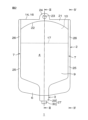
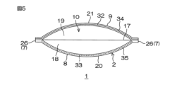
図1は、本発明の一実施形態に係る自立性容器1の模式的な斜視図である。図2は、本発明の一実施形態に係る自立性容器1の模式的な正面図である。図3は、本発明の一実施形態に係る自立性容器1の模式的な断面図であって、図2のIII-III断面を示す図である。図4は、本発明の一実施形態に係る自立性容器1の模式的な断面図であって、図2のIV-IV断面を示す図である。図5は、本発明の一実施形態に係る自立性容器1の模式的な底面図である。
Figure 1 is a schematic perspective view of a self-supporting
自立性容器1は、内部に液体を収容し、水平面に置いたときに自立可能なバッグ本体2と、バッグ本体2の内部の収容室4の液体を注出するための口部材3とを含む。この実施形態では、自立性容器1は、収容室4に薬液5が収容された医療用自立性容器1である。
The self-supporting
バッグ本体2は、プラスチックフィルムを用いて形成されている。使用されるフィルムの材料としては、プラスチックであれば特に制限されず、例えば、ポリエチレン、ポリプロピレン、ポリ(4-メチルペンテン)、ポリテトラフルオロエチレン等のポリオレフィン系樹脂、エチレン-テトラシクロドデセン等のポリ環状オレフィン系樹脂等が挙げられ、好ましくは、ポリエチレン、ポリプロピレンが挙げられる。ポリエチレンやポリプロピレン等のポリオレフィン系樹脂は、様々な薬液に対する溶出性が概ね低く、しかも汎用プラスチックである。そのため、薬液への不純物の溶出を抑制することができると共に、バッグ本体2のコストダウンを図ることができる。
The
また、使用されるフィルムの材料は、単独使用または2種以上併用することができる。また、バッグ本体2は、単一の層構造に形成してもよいし、複数の樹脂が積層された多層構造に形成してもよい。
The film materials used can be used alone or in combination of two or more types. The
また、使用されるフィルムの厚さは、例えば、150μm~300μmであってもよい。また、収容室4に収容される薬液5としては、例えば、輸液等の医療用薬液であってもよい。
The thickness of the film used may be, for example, 150 μm to 300 μm. The
バッグ本体2は、口部材3を境界にして一方側および他方側(図1では、それぞれ、紙面前面側および紙面背面側に相当する)にそれぞれ配置され、上側シール部6およびサイドシール部7によって互いに接着された第1フィルム8および第2フィルム9と、第1フィルム8の延長部で構成された底部フィルム10とを含み、底部フィルム10を下側にして水平面に置いたときに自立可能となっている。
The
第1フィルム8および第2フィルム9は、それぞれ、やや縦長の矩形状に形成されている。第1フィルム8および第2フィルム9の上側縁部(口部材3が取り付けられた縁部)が、上側シール部6によって閉塞されている。
The
上側シール部6には、第1フィルム8と第2フィルム9との間に口部材3が挟まれることによって、口部材3が固定されている。
The
底部フィルム10は、第1フィルム8の延長部で構成されている。言い換えれば、底部フィルム10は、第1底部シール部20(後述)によって第1フィルム8から区別されるフィルムであるが、第1フィルム8から一体的に連続するフィルムである。
The
底部フィルム10は、図3に示すように、第1フィルム8の下縁13および第2フィルム9の下縁14にそれぞれ第1縁部15および第2縁部16を有するように、バッグ本体2の内方に折り畳まれて設けられている。
As shown in FIG. 3, the
底部フィルム10は、収容室4に突出するように2つに折り畳まれており、その折り目部17は、図5に示すように、一方のサイドシール部7と他方のサイドシール部7との間にわたって形成されている。これにより、バッグ本体2のガゼット形状の底面が形成され、薬液5の重量によって底部フィルム10の折り目部17が広げられることで自立可能となる。
The
また、底部フィルム10は、折り目部17を境界に、第1フィルム8側の第1部分18および第2フィルム9側の第2部分19を有していてもよい。
The
また、第1フィルム8の下縁13と底部フィルム10の第1縁部15との間の折り目部は、第1底部シール部20によって互いに接着されている。一方、第2フィルム9の下縁14と底部フィルム10の第2縁部16とは、第2底部シール部21によって互いに接着されている。
The fold between the lower edge 13 of the
第1底部シール部20および第2底部シール部21は、図2に示すように、その内縁22が収容室4の外側に膨らむドーム状となるように、収容室4の外側に向かって湾曲して形成されている。したがって、第1底部シール部20および第2底部シール部21は、一対のサイドシール部7の双方から、第1底部シール部20および第2底部シール部21の中央部に向かって幅が徐々に狭くなり、中央部において幅が最小となっている。
As shown in FIG. 2, the first
また、第2底部シール部21には、第2フィルム9と底部フィルム10との境界部32から選択的に突出し、バッグ本体2を吊り下げるための貫通孔23を有する吊り下げ部24が形成されている。
The second
サイドシール部7は、第1サイドシール部25と、第1サイドシール部25に連続する第2サイドシール部26とを含む。
The
第1サイドシール部25は、図4に示すように、バッグ本体2の口部材3側に配置され、第1フィルム8と第2フィルム9との2層構造からなっている。一方、第2サイドシール部26は、折り畳まれて2層構造となっている底部フィルム10と、底部フィルム10を両側から挟む第1フィルム8および第2フィルム9との4層構造からなっている。
As shown in FIG. 4, the first
口部材3は、筒状の本体27と、本体27の内部に設けられたゴム栓28とを含む。
The
本体27は、例えばプラスチック製であり、相対的に径が大きい大径部29と、大径部29よりも小さな径を有する小径部30とを一体的に有している。ゴム栓28は、本体27の小径部30を閉塞するように小径部30に嵌め込まれている。
The
そして、この実施形態では、バッグ本体2の底部フィルム10が、底部フィルム10と一体である第1フィルム8の折り畳みによって形成されているため、各ヒートシール部における端面状態が一律に同じではない。
In this embodiment, the
つまり、第1フィルム8、第2フィルム9および底部フィルム10が、互いに分離されたフィルムである場合には、ヒートシール部は、いずれも、少なくとも2枚のフィルムの端縁同士の重ね合わせ部分に施される。そのため、当該ヒートシール部の端面状態は、少なくとも2枚のフィルムの境界部が明確に現れる状態となる。この実施形態では、図5に示すように、第2底部シール部21は、折り目部分で繋がっているわけではなく、第2フィルム9の下縁14と底部フィルム10の第2縁部16との重ね合わせ部分に施されるものである。そのため、第2フィルム9と底部フィルム10との境界部32が明確に現れる状態となる。
In other words, when the
一方、第1底部シール部20は、第1フィルム8の下縁13と底部フィルム10の第1縁部15との間の折り目部に施されるものである。そのため、第2底部シール部21に比べて、第1フィルム8と底部フィルム10との境界部33が明確に現れるものではない。言い換えれば、第2底部シール部21の端面34には、第1底部シール部20の端面35の境界部33に比べて、第2フィルム9と底部フィルム10との境界部32が明確に現れている。例えば、第2底部シール部21の境界部32は、その端面34に露出するようにはっきり視認できてもよく、第1底部シール部20の境界部33は、その端面35から露出せず、端面35よりも奥側(収容室4側)に薄く視認できる程度であってもよい。
On the other hand, the first
同様に、上側シール部6およびサイドシール部7は、いずれも、第1フィルム8、第2フィルム9および底部フィルム10の端縁同士の重ね合わせ部分に施されるものである。したがって、図1に示すように、上側シール部6の端面37およびサイドシール部7の端面36には、それぞれ、第1フィルム8、第2フィルム9および底部フィルム10の境界部38,39が明確に現れている。
Similarly, the
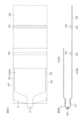
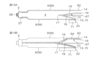
図6Aおよび図6B~図16Aおよび図16Bは、自立性容器1の製造工程の一部を工程順に示す図である。なお、図6Aおよび図6B~図16Aおよび図16Bにおいて示した断面図は、自立性容器1の特定位置での断面を示しているものではなく、説明の便宜上、必要な構成を優先的に表した図である。
Figures 6A and 6B to 16A and 16B are diagrams showing a part of the manufacturing process of the self-supporting
自立性容器1を製造するには、まず、図6Aおよび図6Bに示すように、第1フィルム8と、第1フィルム8よりも短い第2フィルム9とを、第1フィルム8の一部が延長部58として第2フィルム9からはみ出るように重ね合わせる。第1フィルム8および第2フィルム9は、自立性容器1のバッグ本体2を構成する本体フィルム56であり、互いに対向する第1周縁部44および第2周縁部45を有している。
To manufacture the self-supporting
次に、図7Aおよび図7Bに示すように、第1フィルム8および第2フィルム9の周縁部57において、第1フィルム8と第2フィルム9との間に口部材3が挟み込まれる。そして、第1フィルム8および第2フィルム9の周縁部57がヒートシールされることによって、上側シール部6が形成される。
Next, as shown in Figures 7A and 7B, the
次に、図8Aおよび図8Bに示すように、第1フィルム8および第2フィルム9の第1周縁部44の一部、ならびに第1フィルム8および第2フィルム9の第2周縁部45の一部が、金型61で加熱される。
Next, as shown in Figures 8A and 8B, a portion of the first
これにより、第1フィルム8および第2フィルム9がヒートシールされ、上側シール部6および上側シール部6に連続する第1サイドシール部25が形成される。なお、上側シール部6および一対の第1サイドシール部25は、製造効率の関係上、同時に形成することもできる。
This heat seals the
次に、図9Aおよび図9Bに示すように、第1フィルム8の第1サイドシール部25よりも延長部58側の所定位置に、第1折り目部59および第2折り目部60が形成される。第1折り目部59は、第1フィルム8における第2フィルム9に対向する領域に形成され、第2折り目部60は、第1フィルム8の延長部58に形成される。
Next, as shown in Figures 9A and 9B, a
より具体的には、上側シール部6に沿うように、第1フィルム8が選択的に金型63で加熱されることによってフィルム材料が軟化する。これにより、第1フィルム8の幅方向一端から他端まで至る線状の第1折り目部59および第2折り目部60が形成される。なお、本体フィルム56が比較的薄いフィルムで構成されている場合には、第1折り目部59および第2折り目部60のフィルム材料を軟化させなくてもよい。
More specifically, the
次に、図10Aおよび図10Bに示すように、第1フィルム8の延長部58が、第1折り目部59および第2折り目部60を境界に蛇腹状に折り畳まれ、第2折り目部60が内側となるように、底部フィルム10として第1フィルム8と第2フィルム9との間に挟まれる。この際、先の工程で第1折り目部59および第2折り目部60のフィルム材料が軟化していれば、第1フィルム8の延長部58を折り畳む工程を効率よく行うことができる。
Next, as shown in Figures 10A and 10B, the
また、この工程では、第2フィルム9および底部フィルム10の重ね合わせ部分が第2延長部62として、第1折り目部59で構成される第1フィルム8の下縁13よりもはみ出るように(突出するように)、第1フィルム8の延長部58が折り畳まれる。
In addition, in this process, the
次に、図11Aおよび図11Bに示すように、第2フィルム9の第1周縁部44および第2周縁部45のヒートシールされていない残りの部分、および底部フィルム10の第2部分19が金型69で加熱される。これにより、第2フィルム9および底部フィルム10がヒートシールされ、第1サイドシール部25に連続する第1下側サイドシール部64が形成される。
Next, as shown in Figures 11A and 11B, the remaining portions of the first
このとき、第2フィルム9の下縁14と底部フィルム10の第2縁部16とをずらした状態(例えば、底部フィルム10の第2縁部16が、第2フィルム9の下縁14よりも突出した状態)で、第1下側サイドシール部64を形成することが好ましい。これにより、後述する本体フィルム56の内部に薬液5を注入する際に、第2フィルム9と底部フィルム10との間を簡単に開けることができる。第2フィルム9と底部フィルム10とをずらす作業は、前述の第1フィルム8の延長部58の折り畳み工程で行ってもよい。
At this time, it is preferable to form the first lower
また、図11Bに示すように、ヒートシールの際、底部フィルム10の第1部分18と第2部分19との間に遮熱板65を入れておけば、金型69からの熱を遮熱板65で遮断できるので、この工程でヒートシールする必要のない第1フィルム8と底部フィルム10の第1部分18とがヒートシールされることを防止することができる。
In addition, as shown in FIG. 11B, if a
次に、図12、図13Aおよび図13Bに示すように、第1フィルム8の第1周縁部44および第2周縁部45のヒートシールされていない残りの部分、底部フィルム10の第1部分18、ならびに第1折り目部59が金型71で加熱される。これにより、第1フィルム8および底部フィルム10がヒートシールされ、第2下側サイドシール部66および第1底部シール部20が同時に形成される。なお、第2下側サイドシール部66および第1底部シール部20は、製造効率の関係上、同時に形成したが、別々の金型を用いて別工程で形成することもできる。
Next, as shown in Figures 12, 13A and 13B, the remaining unheat-sealed portions of the first
このヒートシールのときも、図13Aおよび図13Bに示すように、底部フィルム10の第1部分18と第2部分との間に遮熱板67を入れておけば、金型71からの熱を遮熱板67で遮断でき、底部フィルム10の第2部分19側に余計な熱が伝わることを防止することができる。特に、この工程では、第2フィルム9の下縁14と底部フィルム10の第2縁部16との間をヒートシールせずに、薬液5の注入のための開口として確保しておく必要があるため、遮熱板67を用いることが好ましい。
Even during this heat sealing, if a
次に、図14Aおよび図14Bに示すように、第2フィルム9の下縁14と底部フィルム10の第2縁部16との間の開口68から、本体フィルム56の内部に薬液5が注入される。
Next, as shown in Figures 14A and 14B, the
次に、図15Aおよび図15Bに示すように、第2フィルム9の下縁14および底部フィルム10の第2縁部16が、金型72で加熱される。これにより、第2フィルム9および底部フィルム10がヒートシールされ、第2底部シール部21が形成される。このとき、第2底部シール部21は、第2延長部62に貫通孔23を有する吊り下げ部24を有するパターンで形成される。その後、第2底部シール部21および吊り下げ部24以外の第2フィルム9および底部フィルム10が、打ち抜きによって取り除かれる。
Next, as shown in Figures 15A and 15B, the
また、このヒートシールのときも、図15Bに示すように、底部フィルム10の第1部分18と第2部分19との間に遮熱板70を入れておけば、金型72からの熱を遮熱板70で遮断でき、底部フィルム10の第1部分18側に余計な熱が伝わることを防止することができる。
Also, during this heat sealing, if a
次に、図16Aおよび図16Bに示すように、第1下側サイドシール部64および第2下側サイドシール部66を重ね合わせて、金型73で加熱される。これにより、第1下側サイドシール部64および第2下側サイドシール部66がヒートシールされ、第2サイドシール部26が形成される。以上の工程を経て、前述の自立性容器1が得られる。
Next, as shown in Figures 16A and 16B, the first lower
以上の方法によれば、第1フィルム8の延長部58の折り畳みによって底部フィルム10が形成される(図10A参照)。そのため、従来のように、筒状インフレーションフィルムの両側が底部フィルムであるという制約がない。したがって、バッグ本体2の材料となるフィルムの種類によらず、種々の大きさの自立性容器1を作製することができる。その結果、フィルム材料を有効活用し、かつ低コストで自立性容器を提供することができる。
According to the above method, the
なお、自立性容器1は、第1フィルム8および第2フィルム9の2枚のフィルムから作製してもよいが、1枚のインフレーションフィルムから作製することもできる。
The self-supporting
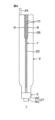
その場合、まず、図17Aおよび図17Bに示すように、扁平な筒状のインフレーションフィルム40に、第1目印41および第2目印42が設けられる。第1目印41および第2目印42は、例えば、熱溶着や超音波溶着など公知の手段によってインフレーションフィルム40に接着された口部材であってもよい。
In this case, first, as shown in Figures 17A and 17B, a
より具体的には、インフレーションフィルム40は、軸方向一端側の開口43に沿う第1周縁部44と、第1周縁部44に直交する第3周縁部46および第4周縁部47を有しており、第3周縁部46および第4周縁部47が折り目部となるように2つに折り畳まれている。第3周縁部46および第4周縁部47は、インフレーションフィルム40の幅方向において互いに対向している。
More specifically, the
そして、インフレーションフィルム40の一方側の外表面49において、第3周縁部46と第4周縁部47との間の中間部48よりも第3周縁部46側の第1領域51に、第1目印41が設けられる。一方、第2目印42は、インフレーションフィルム40の他方側の外表面50において、第3周縁部46と第4周縁部47との間の中間部48よりも第4周縁部47側の第2領域52に設けられる。第1目印41および第2目印42は、インフレーションフィルム40の長さ方向に沿って、所定の間隔を空けて順に設けられる。
The
その後、第1目印41および第2目印42が1つずつ含まれるように、インフレーションフィルム40が幅方向に沿って切断される。これにより、第1目印41および第2目印42を1つずつ備えるインフレーションフィルム40が得られる。切り出されたインフレーションフィルム40は、軸方向他端側の開口53に沿い、インフレーションフィルム40の軸方向において第1周縁部44と対向する第2周縁部45を備えている。
Then, the
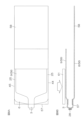
次に、図18Aおよび図18Bに示すように、インフレーションフィルム40が、第1目印41および第2目印42をそれぞれ含む第1本体フィルム54および第2本体フィルム55に切断される。
Next, as shown in Figures 18A and 18B, the
より具体的には、例えば中間部48に沿って第1領域51および第2領域52を分けるようにインフレーションフィルム40が切断される。これにより、第1目印41を備える第1本体フィルム54と、第2目印42を備える第2本体フィルム55とが得られる。なお、以下では、第1目印41を備える第1本体フィルム54、および第2目印42を備える第2本体フィルム55を纏めて、本体フィルム56として説明する。
More specifically, the
次に、図19Aおよび図19Bに示すように、予め定めた第3折り目部74を境界にして区別された本体フィルム56の第1フィルム8と第2フィルム9とを、第1フィルム8の一部が延長部58として第2フィルム9からはみ出るように重ね合わせる。
Next, as shown in Figures 19A and 19B, the
この実施形態では、図17Aおよび図17Bの工程において、インフレーションフィルム40の第3周縁部46および第4周縁部47から内側に離した位置に第1目印41および第2目印42を取り付けたため、第1目印41および第2目印42の位置を境界にして、当該位置から切断部(中間部48)までの距離が長い領域と短い領域とに分けられる。したがって、第1目印41および第2目印42の位置を第3折り目部74として本体フィルム56を折り畳むことによって、本体フィルム56の長い領域を第1フィルム8、短い領域を第2フィルム9として簡単に区別することができる。
17A and 17B, the first and
そして、第1フィルム8および第2フィルム9の第3折り目部74、第1フィルム8および第2フィルム9の第1周縁部44の一部、ならびに第1フィルム8および第2フィルム9の第2周縁部45の一部が、金型61で加熱される。
Then, the
これにより、第1フィルム8および第2フィルム9がヒートシールされ、上側シール部6および上側シール部6に連続する第1サイドシール部25が同時に形成される。なお、上側シール部6および一対の第1サイドシール部25は、製造効率の関係上、同時に形成したが、別々の金型を用いて別工程で形成することもできる。
This causes the
その後は、図9A,9B~図16A,16Bと同様の工程を経ることによって、自立性容器1が得られる。
Then, the self-supporting
以上の方法によれば、インフレーションフィルム40の押出機で製造される扁平な筒状インフレーションフィルム40を、扁平形状の状態から加工することによって自立性容器1を形成することができる。
According to the above method, the flat
つまり、既存のインフレーションフィルム成形装置の巻取りローラで回収した後のインフレーションフィルム40を利用して自立性容器1を形成することができる。そのため、インフレーションフィルム成形装置を改良することなく、1枚のフィルムから自立性容器1を製造することができるので、コストの上昇を抑制することができる。
In other words, the self-supporting
また、インフレーションフィルム40を軸方向に沿って切断するときの位置を調節することによって、互いに長さが異なる2種類の本体フィルム54,55を得ることができる。たとえば、図18Aの切断線75の位置のように、切断位置を中間部48よりも第4周縁部47側にずらせば、第3周縁部46側で相対的に長い第1本体フィルム54を得ることができ、第4周縁部47側で第1本体フィルム54よりも相対的に短い第2本体フィルム55を得ることができる。その結果、1種類のインフレーションフィルム40から、互いに大きさが異なる2種類の自立性容器1を作製することができる。
In addition, by adjusting the position when cutting the
また、底部フィルム10が、本体フィルム56(第1フィルム8および第2フィルム9)と別々のフィルムとして形成されるのではなく、1枚のフィルムから本体フィルム56および底部フィルム10が一体的に形成される。したがって、この点においても、少なくとも2枚のフィルムを使用して自立性容器1が形成される場合に比べて、低コストで自立性容器1を製造することができる。
In addition, the
また、基本的に、インフレーションフィルム40の折り畳みおよびヒートシールによって自立性容器1を製造することができるので、製造時に、バッグ本体2の内部の無菌性を維持しやすくすることができる。その結果、無菌性の高い自立性容器1を製造することができる。
In addition, since the self-supporting
以上、本発明の一実施形態を説明したが、本発明は、他の形態で実施することもできる。 Although one embodiment of the present invention has been described above, the present invention can also be implemented in other forms.
例えば、図17A,17B~図19A,19Bに示した工程を含む自立性容器1の製造方法を、インフレーションフィルム40ではなく、例えばTダイ成形等の他のフィルム成形法によって得られた2枚のフィルムを貼り合わせた後に、インフレーションフィルム40と同様にして行うこともできる。
For example, the method for manufacturing the self-supporting
例えば、自立性容器1に収容される液体は、薬液5の他、飲料等であってもよい。
For example, the liquid contained in the self-supporting
その他、特許請求の範囲に記載された事項の範囲で種々の設計変更を施すことが可能である。 In addition, various design changes may be made within the scope of the claims.
1 自立性容器
2 バッグ本体
3 口部材
4 収容室
5 薬液
6 上側シール部
7 サイドシール部
8 第1フィルム
9 第2フィルム
10 底部フィルム
13 (第1フィルムの)下縁
14 (第2フィルムの)下縁
15 (底部フィルムの)第1縁部
16 (底部フィルムの)第2縁部
17 折り目部
18 (底部フィルムの)第1部分
19 (底部フィルムの)第2部分
20 第1底部シール部
21 第2底部シール部
22 内縁
23 貫通孔
24 吊り下げ部
25 第1サイドシール部
26 第2サイドシール部
27 本体
28 ゴム栓
29 大径部
30 小径部
31 空間
32 (第2底部シール部の)境界部
33 (第1底部シール部の)境界部
34 (第2底部シール部の)端面
35 (第1底部シール部の)端面
36 (サイドシール部の)端面
37 (上側シール部の)端面
38 (上側シール部の)境界部
39 (サイドシール部の)境界部
40 インフレーションフィルム
41 第1目印
42 第2目印
43 (インフレーションフィルムの)開口
44 (インフレーションフィルムの)第1周縁部
45 インフレーションフィルムの)第2周縁部
46 (インフレーションフィルムの)第3周縁部
47 (インフレーションフィルムの)第4周縁部
48 中間部
49 一方側の外表面
50 他方側の外表面
51 第1領域
52 第2領域
53 (インフレーションフィルムの)開口
54 第1本体フィルム
55 第2本体フィルム
56 本体フィルム
57 周縁部
58 (第1フィルムの)延長部
59 第2折り目部
60 第3折り目部
61 金型
62 第2延長部
63 金型
64 第1下側サイドシール部
65 遮熱板
66 第2下側サイドシール部
67 遮熱板
68 開口
69 金型
70 遮熱板
71 金型
72 金型
73 金型
74 第3折り目部
75 切断線
LIST OF SYMBOLS 1 Self-supporting container 2 Bag body 3 Mouth member 4 Storage chamber 5 Drug solution 6 Upper seal portion 7 Side seal portion 8 First film 9 Second film 10 Bottom film 13 Lower edge (of first film) 14 Lower edge (of second film) 15 First edge (of bottom film) 16 Second edge (of bottom film) 17 Fold portion 18 First portion (of bottom film) 19 Second portion (of bottom film) 20 First bottom seal portion 21 Second bottom seal portion 22 Inner edge 23 Through hole 24 Hanging portion 25 First side seal portion 26 Second side seal portion 27 Body 28 Rubber stopper 29 Large diameter portion 30 Small diameter portion 31 Space 32 Boundary portion (of second bottom seal portion) 33 Boundary (of first bottom seal portion) 34 End face (of second bottom seal portion) 35 End face (of first bottom seal portion) 36 End face (of side seal portion) 37 End face (of upper seal portion) 38 Boundary (of upper seal portion) 39 Boundary (of side seal portion) 40 Blown film 41 First mark 42 Second mark 43 Opening (of blown film) 44 First peripheral portion (of blown film) 45 Second peripheral portion (of blown film) 46 Third peripheral portion (of blown film) 47 Fourth peripheral portion (of blown film) 48 Middle portion 49 Outer surface of one side 50 Outer surface of the other side 51 First region 52 Second region 53 Opening (of blown film) 54 First main film 55 Second main film 56 Main film 57 Periphery 58 Extension (of first film) 59 Second fold 60 Third fold 61 Mold 62 Second extension 63 Mold 64 First lower side seal 65 Heat shield 66 Second lower side seal 67 Heat shield 68 Opening 69 Mold 70 Heat shield 71 Mold 72 Mold 73 Mold 74 Third fold 75 Cutting line
Claims (5)
前記口部材を境界にして一方側および他方側にそれぞれ配置され、上側シール部およびサイドシール部によって互いに接着された第1フィルムおよび第2フィルムと、前記第1フィルムの延長部で構成された底部フィルムとを含み、前記底部フィルムを下側にして水平面に置いたときに自立可能なバッグ本体と、
前記バッグ本体の内部の収容室に収容された液体とを含み、
前記底部フィルムは、前記第1フィルムの下縁および前記第2フィルムの下縁にそれぞれ第1縁部および第2縁部を有するように、前記バッグ本体の内方に折り畳まれて設けられており、
前記第1フィルムの前記下縁と前記底部フィルムの前記第1縁部との間の折り目部分は、第1底部シール部によって互いに接着されており、
前記第2フィルムの前記下縁と前記底部フィルムの前記第2縁部とは、第2底部シール部によって互いに接着されており、
前記第2底部シール部の端面は、前記第2フィルムと前記底部フィルムとがシール部によって互いに接着されており、
前記第1底部シール部の端面は、前記底部フィルムが折り畳まれて形成されており、
前記底部フィルムは、前記収容室に突出するように、一方の前記サイドシール部と他方の前記サイドシール部との間にわたって形成された底部折り目部において2つに折り畳まれており、
前記バッグ本体は、前記液体の重量によって前記底部折り目部が広げられることで自立可能となる、自立性容器。 A mouth member for pouring out the liquid therein;
a bag body including a first film and a second film respectively arranged on one side and the other side of the mouth member and bonded to each other by an upper seal portion and a side seal portion, and a bottom film formed by an extension of the first film, the bag body being self-supporting when placed on a horizontal surface with the bottom film facing down ;
A liquid contained in a storage chamber inside the bag body ,
the bottom film is folded inwardly of the bag body so as to have a first edge portion and a second edge portion at a lower edge of the first film and a lower edge of the second film, respectively;
a fold between the bottom edge of the first film and the first edge of the bottom film is adhered to one another by a first bottom seal;
the bottom edge of the second film and the second edge of the bottom film are adhered to one another by a second bottom seal;
The end surface of the second bottom seal portion is such that the second film and the bottom film are bonded to each other by a seal portion,
The end surface of the first bottom seal portion is formed by folding the bottom film,
the bottom film is folded in two at a bottom fold portion formed between one of the side seal portions and the other of the side seal portions so as to protrude into the storage chamber;
The bag body is a self-supporting container that can stand on its own by the weight of the liquid expanding the bottom fold portion .
前記口部材を境界にして一方側および他方側にそれぞれ配置され、上側シール部およびサイドシール部によって互いに接着された第1フィルムおよび第2フィルムと、前記第1フィルムの延長部で構成された底部フィルムとを含み、前記底部フィルムを下側にして水平面に置いたときに自立可能なバッグ本体と、
前記バッグ本体の内部の収容室に収容された液体とを含み、
前記底部フィルムは、前記第1フィルムの下縁および前記第2フィルムの下縁にそれぞれ第1縁部および第2縁部を有するように、前記バッグ本体の内方に折り畳まれて設けられており、
前記第1フィルムの前記下縁と前記底部フィルムの前記第1縁部との間の折り目部分は、第1底部シール部によって互いに接着されており、
前記第2フィルムの前記下縁と前記底部フィルムの前記第2縁部とは、第2底部シール部によって互いに接着されており、
前記第2底部シール部の端面には、前記第1底部シール部の端面における前記第1フィルムと前記底部フィルムとの境界部に比べて、前記第2フィルムと前記底部フィルムとの境界部が明確に現れており、
前記底部フィルムは、前記収容室に突出するように、一方の前記サイドシール部と他方の前記サイドシール部との間にわたって形成された底部折り目部において2つに折り畳まれており、
前記バッグ本体は、前記液体の重量によって前記底部折り目部が広げられることで自立可能となる、自立性容器。 A mouth member for pouring out the liquid therein;
a bag body including a first film and a second film respectively arranged on one side and the other side of the mouth member and bonded to each other by an upper seal portion and a side seal portion, and a bottom film formed by an extension of the first film, the bag body being self-supporting when placed on a horizontal surface with the bottom film facing down ;
A liquid contained in a storage chamber inside the bag body ,
the bottom film is folded inwardly of the bag body so as to have a first edge portion and a second edge portion at a lower edge of the first film and a lower edge of the second film, respectively;
a fold between the bottom edge of the first film and the first edge of the bottom film is adhered to one another by a first bottom seal;
the bottom edge of the second film and the second edge of the bottom film are adhered to one another by a second bottom seal;
At an end surface of the second bottom seal portion, a boundary portion between the second film and the bottom film appears more clearly than a boundary portion between the first film and the bottom film at an end surface of the first bottom seal portion ;
the bottom film is folded in two at a bottom fold portion formed between one of the side seal portions and the other of the side seal portions so as to protrude into the storage chamber;
The bag body is a self-supporting container that can stand on its own by the weight of the liquid expanding the bottom fold portion .
前記バッグ本体の前記口部材側に配置され、前記第1フィルムと前記第2フィルムとの2層構造からなる第1サイドシール部と、
前記第1サイドシール部に連続した第2サイドシール部であって、折り畳まれて2層構造となっている前記底部フィルムと、前記底部フィルムを両側から挟む前記第1フィルムおよび前記第2フィルムとの4層構造からなる第2サイドシール部とを含む、請求項1または2に記載の自立性容器。 The side seal portion is
a first side seal portion disposed on the mouth member side of the bag body and having a two-layer structure of the first film and the second film;
3. The self-supporting container according to claim 1 or 2, comprising a second side seal portion continuous with the first side seal portion, the second side seal portion being made of a four-layer structure including the bottom film that is folded to form a two-layer structure, and the first film and the second film that sandwich the bottom film from both sides.
Priority Applications (1)
| Application Number | Priority Date | Filing Date | Title |
|---|---|---|---|
| JP2023183045A JP7621680B2 (en) | 2019-04-09 | 2023-10-25 | Self-supporting container |
Applications Claiming Priority (2)
| Application Number | Priority Date | Filing Date | Title |
|---|---|---|---|
| JP2019074311A JP7378762B2 (en) | 2019-04-09 | 2019-04-09 | Self-supporting containers and methods of manufacturing self-supporting containers |
| JP2023183045A JP7621680B2 (en) | 2019-04-09 | 2023-10-25 | Self-supporting container |
Related Parent Applications (1)
| Application Number | Title | Priority Date | Filing Date |
|---|---|---|---|
| JP2019074311A Division JP7378762B2 (en) | 2019-04-09 | 2019-04-09 | Self-supporting containers and methods of manufacturing self-supporting containers |
Publications (3)
| Publication Number | Publication Date |
|---|---|
| JP2023182835A JP2023182835A (en) | 2023-12-26 |
| JP2023182835A5 JP2023182835A5 (en) | 2024-01-11 |
| JP7621680B2 true JP7621680B2 (en) | 2025-01-27 |
Family
ID=72830727
Family Applications (2)
| Application Number | Title | Priority Date | Filing Date |
|---|---|---|---|
| JP2019074311A Active JP7378762B2 (en) | 2019-04-09 | 2019-04-09 | Self-supporting containers and methods of manufacturing self-supporting containers |
| JP2023183045A Active JP7621680B2 (en) | 2019-04-09 | 2023-10-25 | Self-supporting container |
Family Applications Before (1)
| Application Number | Title | Priority Date | Filing Date |
|---|---|---|---|
| JP2019074311A Active JP7378762B2 (en) | 2019-04-09 | 2019-04-09 | Self-supporting containers and methods of manufacturing self-supporting containers |
Country Status (1)
| Country | Link |
|---|---|
| JP (2) | JP7378762B2 (en) |
Citations (5)
| Publication number | Priority date | Publication date | Assignee | Title |
|---|---|---|---|---|
| JP2013500890A (en) | 2009-08-04 | 2013-01-10 | ヴォルパク エス エー ユー | Flexible material package and continuous manufacturing method and machine thereof |
| WO2013054824A1 (en) | 2011-10-11 | 2013-04-18 | 味の素株式会社 | Standing bag infusion container |
| JP2013124135A (en) | 2011-12-16 | 2013-06-24 | Ajinomoto Co Inc | Pouch container |
| WO2018012542A1 (en) | 2016-07-14 | 2018-01-18 | トタニ技研工業株式会社 | Bag making machine and method for manufacturing plastic bag |
| US20180360415A1 (en) | 2017-06-15 | 2018-12-20 | HR Pharmaceuticals, Inc. | Ultrasound Gel Container |
Family Cites Families (4)
| Publication number | Priority date | Publication date | Assignee | Title |
|---|---|---|---|---|
| JPH057641U (en) * | 1991-07-12 | 1993-02-02 | 株式会社大塚製薬工場 | Infusion bag |
| JPH0872896A (en) * | 1994-09-05 | 1996-03-19 | Dainippon Printing Co Ltd | Self-supporting package |
| JP5619501B2 (en) * | 2010-07-20 | 2014-11-05 | エイワイファーマ株式会社 | Standing bag manufacturing method and standing bag |
| JP6046520B2 (en) * | 2013-02-26 | 2016-12-14 | 押尾産業株式会社 | Filling method |
-
2019
- 2019-04-09 JP JP2019074311A patent/JP7378762B2/en active Active
-
2023
- 2023-10-25 JP JP2023183045A patent/JP7621680B2/en active Active
Patent Citations (5)
| Publication number | Priority date | Publication date | Assignee | Title |
|---|---|---|---|---|
| JP2013500890A (en) | 2009-08-04 | 2013-01-10 | ヴォルパク エス エー ユー | Flexible material package and continuous manufacturing method and machine thereof |
| WO2013054824A1 (en) | 2011-10-11 | 2013-04-18 | 味の素株式会社 | Standing bag infusion container |
| JP2013124135A (en) | 2011-12-16 | 2013-06-24 | Ajinomoto Co Inc | Pouch container |
| WO2018012542A1 (en) | 2016-07-14 | 2018-01-18 | トタニ技研工業株式会社 | Bag making machine and method for manufacturing plastic bag |
| US20180360415A1 (en) | 2017-06-15 | 2018-12-20 | HR Pharmaceuticals, Inc. | Ultrasound Gel Container |
Also Published As
| Publication number | Publication date |
|---|---|
| JP7378762B2 (en) | 2023-11-14 |
| JP2023182835A (en) | 2023-12-26 |
| JP2020172277A (en) | 2020-10-22 |
Similar Documents
| Publication | Publication Date | Title |
|---|---|---|
| CN103201095B (en) | Package bag and method for producing same | |
| CN101878163B (en) | Manufacturing method of packaging bag with liquid discharge spout | |
| JP2003034338A (en) | Zippered bag and manufacturing method therefor | |
| JP4231989B2 (en) | Self-supporting bag and its manufacturing method | |
| JP6889994B2 (en) | Packaging bag with spout | |
| AU2017361365B2 (en) | Self-standing bag and method for manufacturing same | |
| JP6349653B2 (en) | Zippered pouch and manufacturing method thereof | |
| JP7621680B2 (en) | Self-supporting container | |
| JP5049537B2 (en) | Self-supporting bag | |
| CN110753663B (en) | Spouted packaging bag, method for manufacturing the same, and spouted packaging bag with contents | |
| JP5000168B2 (en) | Manufacturing method of standing pouch and standing pouch manufactured by the method | |
| JP4074001B2 (en) | Self-supporting pouch | |
| JP2011006115A (en) | Packaging bag and manufacturing method of the same | |
| JP3819188B2 (en) | Liquid container and manufacturing method thereof | |
| US20240278508A1 (en) | A method for manufacturing a pouch for holding therein a liquid | |
| JP5306707B2 (en) | Manufacturing method of gusset type pouch container | |
| JP6797558B2 (en) | Packaging bag and its manufacturing method | |
| JP6250326B2 (en) | Pouch container | |
| JP6626317B2 (en) | Gazette bag with spout and method for producing the same | |
| JP2012017150A (en) | Liquid discharge nozzle | |
| JP2003095287A (en) | Refill bag package | |
| JP6902836B2 (en) | Packaging bag with spout and its manufacturing method | |
| JP5459114B2 (en) | Packaging bag manufacturing method | |
| JP6307812B2 (en) | Method for manufacturing liquid packaging bag | |
| JP7028571B2 (en) | Gazette bag |
Legal Events
| Date | Code | Title | Description |
|---|---|---|---|
| A621 | Written request for application examination |
Free format text: JAPANESE INTERMEDIATE CODE: A621 Effective date: 20231122 |
|
| A521 | Request for written amendment filed |
Free format text: JAPANESE INTERMEDIATE CODE: A523 Effective date: 20231227 |
|
| A977 | Report on retrieval |
Free format text: JAPANESE INTERMEDIATE CODE: A971007 Effective date: 20241025 |
|
| TRDD | Decision of grant or rejection written | ||
| A01 | Written decision to grant a patent or to grant a registration (utility model) |
Free format text: JAPANESE INTERMEDIATE CODE: A01 Effective date: 20241212 |
|
| A61 | First payment of annual fees (during grant procedure) |
Free format text: JAPANESE INTERMEDIATE CODE: A61 Effective date: 20250107 |
|
| R150 | Certificate of patent or registration of utility model |
Ref document number: 7621680 Country of ref document: JP Free format text: JAPANESE INTERMEDIATE CODE: R150 |