JP7621623B2 - Heat sink for UV LED curing device - Google Patents
Heat sink for UV LED curing device Download PDFInfo
- Publication number
- JP7621623B2 JP7621623B2 JP2023128615A JP2023128615A JP7621623B2 JP 7621623 B2 JP7621623 B2 JP 7621623B2 JP 2023128615 A JP2023128615 A JP 2023128615A JP 2023128615 A JP2023128615 A JP 2023128615A JP 7621623 B2 JP7621623 B2 JP 7621623B2
- Authority
- JP
- Japan
- Prior art keywords
- heat sink
- heat
- lateral support
- fixing member
- stacked
- Prior art date
- Legal status (The legal status is an assumption and is not a legal conclusion. Google has not performed a legal analysis and makes no representation as to the accuracy of the status listed.)
- Active
Links
Images

Landscapes
- Engineering & Computer Science (AREA)
- Physics & Mathematics (AREA)
- Mechanical Engineering (AREA)
- General Engineering & Computer Science (AREA)
- Thermal Sciences (AREA)
- Toxicology (AREA)
- Health & Medical Sciences (AREA)
- General Health & Medical Sciences (AREA)
- Led Device Packages (AREA)
- Supply, Installation And Extraction Of Printed Sheets Or Plates (AREA)
- Cooling Or The Like Of Semiconductors Or Solid State Devices (AREA)
- Geometry (AREA)
- Life Sciences & Earth Sciences (AREA)
- Sustainable Development (AREA)
- Plasma & Fusion (AREA)
- Cooling Or The Like Of Electrical Apparatus (AREA)
Description
本発明は空冷式のUV LED硬化器用ヒートシンクに関し、より詳細に説明すると、UV LEDが付着される放熱板と、多数個のヒートパイプと、前記ヒートパイプを放熱板に固定結合させる固定部材と、そして前記ヒートパイプに並んで積層支持される多数枚の積層フィンを含んで構成される、UV LED硬化器用ヒートシンクに関する。 The present invention relates to a heat sink for an air-cooled UV LED curing device, and more specifically, to a heat sink for a UV LED curing device that includes a heat sink plate to which UV LEDs are attached, a number of heat pipes, a fixing member that fixes and connects the heat pipes to the heat sink plate, and a number of stacked fins that are stacked and supported in parallel with the heat pipes.
UV(ultraviolet)硬化器は光開始剤が含まれている紫外線硬化型樹脂を硬化させる機器であって、各種産業分野で接着、塗布、印刷工程などを遂行するのに広く使われている。UV LED硬化器は紫外線光源としてLEDを使うものであって、通常のUVランプを使う場合に比べて装備の規模を縮小し、電力消費量を削減できる長所がある。 UV (ultraviolet) hardeners are devices that harden ultraviolet-curable resins that contain photoinitiators, and are widely used in various industrial fields to carry out adhesion, coating, printing, and other processes. UV LED hardeners use LEDs as an ultraviolet light source, and have the advantage of being smaller in size and consuming less electricity than conventional UV lamps.
UV LED硬化器において光源であるLEDで発生する熱は、UV LEDの寿命と光量を低下させる否定的な影響を及ぼす。そのため、従来にもUV LEDで発生する熱を効率的に冷却させる冷却装置、すなわちヒートシンク(heat sink)が備えられたUV LED硬化器が多様に提案されている。 In UV LED curing devices, the heat generated by the LED, which is the light source, has a negative effect of reducing the lifespan and light output of the UV LED. For this reason, various UV LED curing devices equipped with a cooling device, i.e., a heat sink, that efficiently cools the heat generated by the UV LED have been proposed.
例えば、韓国登録特許第10-1623299号(2016年05月16日)には、紫外線硬化型樹脂でコーティングされた製品をUV LEDで硬化する大面積コーティング用UV LED硬化装置において、LEDモジュールが設置されたヒートシンクと、前記ヒートシンクを囲む水冷ジャケット、そして冷却水循環経路が備えられた放熱器からなる冷却手段が開示されている。 For example, Korean Patent Registration No. 10-1623299 (May 16, 2016) discloses a cooling means for a UV LED curing device for large-area coating that uses UV LEDs to cure products coated with ultraviolet-curable resin, the cooling means comprising a heat sink on which an LED module is installed, a water-cooling jacket surrounding the heat sink, and a radiator equipped with a cooling water circulation path.
そして、韓国登録特許第10-1723130号(2017年03月29日)には、ディスプレイパネルの合着工程に利用される紫外線硬化装置において、多数のLEDを有する発光部の後面に付着される金属ブロックと、前記金属ブロックに沿って冷媒を循環させる冷却管を含んで構成される冷却モジュールが開示されている。 And Korean Patent Registration No. 10-1723130 (March 29, 2017) discloses a cooling module in an ultraviolet curing device used in the bonding process of display panels, which includes a metal block attached to the rear surface of a light-emitting unit having multiple LEDs, and a cooling tube that circulates a refrigerant along the metal block.
また、韓国登録特許第10-2016288号(2019年08月23日)には、UV
LEDを利用した印刷用UVインク硬化装置において、印刷物が通過する第1ケースおよび第2ケースと、前記第1ケース内で印刷物に向かってUV光を照射するUV LED基板と、前記UV LED基板で発生する熱を放出させる放熱板と、前記放熱板を通じて空気を循環させる放熱冷却ファンを含んで構成されるUVインク硬化装置が開示されている。
In addition, Korean Patent No. 10-2016288 (August 23, 2019) states that UV
The present invention discloses a UV ink curing device for printing using LEDs, the UV ink curing device including a first case and a second case through which a printed material passes, a UV LED board that irradiates UV light toward the printed material inside the first case, a heat sink that releases heat generated by the UV LED board, and a heat dissipation cooling fan that circulates air through the heat sink.
最後に、韓国登録特許第10-2402027号(2022年05月20日)には、通常のUV印刷装置に装着されて放熱構造を改善することによって、印刷物の変形と印刷品質の低下を防止できるLED UV硬化器が開示されている。添付図1は、前記LED UV硬化器の硬化モジュールを示したものであり、印刷物の上部に配置される第1モジュールAと、印刷物の下部に配置される第2モジュールBを含む。 Finally, Korean Patent Registration No. 10-2402027 (May 20, 2022) discloses an LED UV curing device that is mounted on a normal UV printing device and improves the heat dissipation structure to prevent deformation of the printed material and deterioration of print quality. Attached FIG. 1 shows the curing module of the LED UV curing device, which includes a first module A arranged above the printed material and a second module B arranged below the printed material.
前記第1モジュールAは印刷物の表面にUV光を照射するもので、ハウジングA1、光照射ユニットA2、反射板A3、拡散板A4および放熱部A5で構成される。前記放熱部A5はヒートシンクA51、放熱ファンA52およびヒートパイプA53を含み、前記ヒートシンクA51は放熱プレートA511と放熱フィンA512を含んで構成される。 The first module A irradiates the surface of the printed material with UV light and is composed of a housing A1, a light irradiation unit A2, a reflector A3, a diffusion plate A4 and a heat dissipation section A5. The heat dissipation section A5 includes a heat sink A51, a heat dissipation fan A52 and a heat pipe A53, and the heat sink A51 includes a heat dissipation plate A511 and a heat dissipation fin A512.
本発明に係るヒートシンクは、添付図1のLED UV硬化器で放熱部A5に対応し得る。図1でその他の未説明図面符号に対する説明は省略する。 The heat sink according to the present invention may correspond to the heat dissipation part A5 in the LED UV curing device shown in FIG. 1. Explanations of other unexplained reference symbols in FIG. 1 will be omitted.
一般的にUV LED硬化器に使われるヒートシンクは空冷式と水冷式に区分することができる。空冷式は水冷式に比べて構造が簡便で製造原価が安い長所があるが、相対的に冷却効果が低い短所がある。 The heat sinks generally used in UV LED curing devices can be divided into air-cooled and water-cooled types. Air-cooled types have the advantages of simpler structure and lower manufacturing costs compared to water-cooled types, but have the disadvantage of relatively low cooling effect.
したがって、本発明の目的は、UV LED硬化器用冷却装置で使うのに非常に適合であり、特に空冷式でありながらも水冷式と略類似する冷却効果を示すほど冷却効率が優秀な空冷式ヒートシンクを提供することである。 Therefore, the object of the present invention is to provide an air-cooled heat sink that is highly suitable for use in a cooling device for a UV LED curing device, and has excellent cooling efficiency, so that it exhibits a cooling effect similar to that of a water-cooled type, even though it is air-cooled.
また、本発明の目的は、UV LED硬化器の使用目的に応じて冷却効率を容易に調節でき、ひいては組立工程と維持および保守が迅速容易な空冷式ヒートシンクを提供することである。 Another object of the present invention is to provide an air-cooled heat sink that allows for easy adjustment of cooling efficiency depending on the intended use of the UV LED curing device, and thus allows for quick and easy assembly and maintenance.
本発明に係るUV LED硬化器用ヒートシンクは、 The heat sink for the UV LED curing device according to the present invention is
一面にUV LED11が並んで付着され、他面には所定の長さL1に拡張された円弧状上向きアーク溝12が並んで配置されている金属材質の放熱板10と;
A
両側端部が密封された円筒状金属管の内部に液体が満たされものであって、前記放熱板10の上向きアーク溝12内に密着挿入される横支持部21と、前記横支持部21の両側端部からそれぞれ放熱板10に対して垂直方向に折り曲げられた縦折り曲げ部22a、22bを有する多数個のヒートパイプ20と;
A cylindrical metal tube with both ends sealed and filled with liquid, a lateral support part 21 that is tightly inserted into the upward arc groove 12 of the
前記ヒートパイプ20の横支持部21を覆って前記ヒートパイプ20をそれぞれ放熱板10に固定結合させるものであって、一面には長さ方向に沿って前記上向きアーク溝12に対応する下向きアーク溝31が並んで備えられている固定部材30と;
A
前記ヒートパイプ20の両側の縦折り曲げ部22a、22bに挿入支持された状態で放熱板10の他面上に一定の間隔をおいて幾重にも配置される金属材質の薄板であって、前記縦折り曲げ部22a、22bがそれぞれ密着挿入される多数個のパイプ挿入孔41が穿孔されており、前記パイプ挿入孔41の周りにはスリーブ42が一定の高さL3で突出している多数枚の積層フィン40;を含んで構成されていることを特徴とする。
It is characterized in that it is made up of a number of stacked
前記放熱板10の上向きアーク溝12は、互いに隣接する上向きアーク溝12の両側端部が互いに行き違うように一個ずつ交互に配置されていることを特徴とする。
The upward arc grooves 12 of the
前記放熱板10に結合されるヒートパイプ20と積層フィン40は一つの積層フィンモジュールM1、M2の形態で組立および分離され、前記積層フィンモジュールM1、M2
は8~16個のヒートパイプに20~100枚の積層フィン40を挿入固定して構成されていることを特徴とする。
The
The heat exchanger is characterized in that it is constructed by inserting and fixing 20 to 100 stacked fins 40 into 8 to 16 heat pipes.
本発明に係るUV LED硬化器用ヒートシンクは、UV LED11で発生する熱が放熱板10とヒートパイプ20を通じて積層フィン40に伝達された後に速かに空気中に拡散するので、空冷式でありながらも水冷式と略類似する冷却効果を有する。
The heat sink for a UV LED curing device according to the present invention has a cooling effect similar to that of a water-cooled type, even though it is an air-cooled type, because the heat generated by the
本発明に係るUV LED硬化器用ヒートシンクは、ヒートパイプ20と積層フィン40の個数および規格を調節することによって冷却効率を容易に調節でき、ひいては積層フィンモジュールM1、M2を使って組立と分解はもちろん、維持および保守を容易にできる効果がある。
The heat sink for a UV LED curing device according to the present invention can easily adjust the cooling efficiency by adjusting the number and size of the
以下、添付した図面を利用して本発明を詳細に説明する。ただし、添付図面は本発明の好ましい実施例を例示したものであるので、これらの実施例によって本発明の権利範囲が制限されるものではない。また、本発明の実施に必ず必要な構成であるとしても従来技術に紹介されていたり、通常の技術者が公知技術から容易に実施できる事項については具体的な説明を省略する。 The present invention will now be described in detail with reference to the attached drawings. However, the attached drawings are merely illustrative of preferred embodiments of the present invention, and the scope of the invention is not limited by these embodiments. Furthermore, detailed descriptions of configurations that are essential to the implementation of the present invention will be omitted if they have been introduced in the prior art or can be easily implemented by ordinary engineers using known techniques.
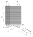
本発明に係るUV LED硬化器用ヒートシンクは、添付した図2~図4に示されているように、UV硬化器用LEDが付着される放熱板10と、多数個のヒートパイプ20と、前記ヒートパイプ20を放熱板10に固定結合させる固定部材30と、そして前記ヒートパイプ20に並んで積層支持される多数枚の積層フィン40を含んで構成される。前記積層フィン40の側面には通常の冷却ファン(図示せず)が配置されてもよい。
As shown in the attached Figs. 2 to 4, the heat sink for a UV LED curing device according to the present invention comprises a
まず、放熱板10は金属材質の長方形の板状であって、一面にはUV LED11が並んで付着され、他面には多数個の上向きアーク溝12が並んで配置されている構造を有する。添付図5は熱伝導率(thermal conductivity)が優秀な銅材質からなり、幅95mm、長さ340mm、厚さ7mmの規格を有する長方形板状の放熱板10を例示したものである。
First, the
前記UV LED11は例えば、315~400nm程度の波長範囲で1個当り約200W程度の出力で紫外線光を放出するLEDを使うことができる。このようなUV LED11はCOBタイプやパッケージタイプであって、通常の固定ねじを利用して放熱板10の一面に付着することができ、このために図4のUV LED11にはねじ孔が備えら
れている。
The
前記上向きアーク溝12は例えば、半径が3mmである円弧状、好ましくは半円状の溝であって、その長さL1は前記放熱板10の幅より短い60~80mm程度であることが好ましい。添付図5の放熱板10には長さL1が同一である上向きアーク溝12が48個放熱板10の長さ方向に沿って並んで配置されている様子を示している。
The upward arc groove 12 is, for example, an arc-shaped groove, preferably a semicircular groove, with a radius of 3 mm, and its length L1 is preferably about 60 to 80 mm, shorter than the width of the
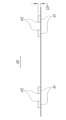
次に、ヒートパイプ20は、図6のように両側端部が密封された円筒状金属管の内部に液体が満たされものであって、それぞれ横支持部21と縦折り曲げ部22a、22bが「U」の形状で折り曲げられた構造を有する。前記ヒートパイプ20を構成する金属管は銅材質からなり、その内部には水が満たされていることが好ましい。
The
前記横支持部21は放熱板10の上向きアーク溝12内に密着挿入されるもので、その半径および長さL1が前記上向きアーク溝12の半径および長さL1と同一である。前記横支持部21は円形断面の半分程度が上向きアーク溝12内に収容されることが好ましい。
The lateral support portion 21 is inserted closely into the upward arc groove 12 of the
前記縦折り曲げ部22a、22bは横支持部21の両側端部からそれぞれ放熱板10に対して垂直方向に折り曲げられたもので、その端部はそれぞれ密封されている。前記ヒートパイプ20の個数は放熱板10に備えられた上向きアーク溝12の個数と同一である。
The vertical bends 22a and 22b are bent from both ends of the horizontal support 21 in a direction perpendicular to the
前記固定部材30はヒートパイプ20の横支持部21を覆って前記ヒートパイプ20をそれぞれ独立的に放熱板10に固定結合させる機能をする。前記固定部材30の材質はアルミニウムからなり得、その長さは前記放熱板10の長さと同一である。
The
図7に示されているように、前記固定部材30の一面には長さ方向に沿って前記上向きアーク溝12に対応する下向きアーク溝31が並んで備えられている。前記下向きアーク溝31の半径および間隔は前記上向きアーク溝12の半径および間隔と同一である。そのため、上向きアーク溝12と下向きアーク溝31が合わせられて横支持部21の上半部と下半部を共に囲む。
As shown in FIG. 7, downward
また、前記固定部材30の他面には長さ方向に沿って放熱溝32が備えられている。前記放熱溝32は固定部材30の表面積を拡張させて放熱効果を高める機能をする。前記固定部材30はヒートパイプ20の横支持部21とともに溶接によって放熱板10に付着されてもよく、別途の固定ねじによって放熱板10に結合され得る。このために図5の放熱板10には適所に多数個のねじ孔が備えられている。
The other side of the fixing
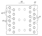
最後に、前記積層フィン40は金属材質の薄板の形状であって、前記縦折り曲げ部22a、22bに支持された状態で放熱板10の他面上に一定の間隔をおいて幾重にも配置される。図8には厚さが0.3~0.7mmであるアルミニウム薄板であって、横115mm、縦84mmである四角形状の積層フィン40が例示されている。
Finally, the
前記積層フィン40にはヒートパイプ20の両側の縦折り曲げ部22a、22bがそれぞれ密着挿入される多数個のパイプ挿入孔41が並んで穿孔されている。前記パイプ挿入孔41の内径は前記縦折り曲げ部22a、22bの直径と同一である。そのため、前記積層フィン40は前記縦折り曲げ部22a、22bに挿入支持された状態で一定の間隔をおいて幾重にも配置される。
The
前記積層フィン40のパイプ挿入孔41には図9のように、所定高さL3のスリーブ42が備えられていることが好ましい。前記スリーブ42の内径は縦折り曲げ部22a、2
2bの直径と同一である。そのため、前記スリーブ42は縦折り曲げ部22a、22bに対する積層フィン40の支持力を高め、同時に各積層フィン40の間の上下の間隔を一定に離隔させる機能をする。前記スリーブ42の高さHは1.5~3mmであることが好ましい。
It is preferable that the
The diameter of the
一方、図5に示されているように、前記放熱板10に配置される上向きアーク溝12は、互いに隣接する上向きアーク溝12の両側端部が互いに行き違うように一個ずつ交互に配置されていることが好ましい。このようになると、図6および図8のように互いに隣接したヒートパイプ20の縦折り曲げ部22a、22bとこれに対応する積層フィン40のパイプ挿入孔41もジグザグ状に交互に配置される。
As shown in FIG. 5, it is preferable that the upward arc grooves 12 arranged on the
したがって、前記縦折り曲げ部22a、22bの間で十分な空間が確保されて積層フィン40の側面に設置された冷却ファン(図示せず)で提供される風が渦流現象を起こしながら放熱効果を高める効果があり、ひいては前記パイプ挿入孔41の間の間隔が広くなって積層フィン40の構造的な強度が増加する効果を得ることができる。
As a result, sufficient space is secured between the vertical bends 22a and 22b, and the wind provided by the cooling fan (not shown) installed on the side of the stacked
因みに、ヒートパイプ20の縦折り曲げ部22a、22bが一列で並んで配置されると、互いに隣接した縦折り曲げ部22a、22bが互いに密着して空気の流れを遮断する壁を作るので、相対的に放熱効果が低下する。そして、積層フィン40のパイプ挿入孔41が1列で並んで配置されると、互いに隣接したパイプ挿入孔41の間の間隔が過度に狭くなって、ちょっと間違えばパイプ挿入孔41に沿って積層フィン40が曲がったり切断されることもある。
Incidentally, if the vertical bent portions 22a, 22b of the
これまで長さL1が同一である上向きアーク溝12の端部が互いに行き違うように交互に配置された放熱板10を使う場合を説明したが、図10は本発明の他の実施例として長さL1a、L1bが互いに異なる2種類の上向きアーク溝12a、12bが交互に配置された放熱板10aを示している。前記放熱板10aにおいても互いに隣接する二つの上向きアーク溝12a、12bの両側端部が互いに行き違うように配置されている。図10の放熱板10aを使う場合、前記上向きアーク溝12a、12bの長さL1a、L1bによって横支持部21の長さが互いに異なる2種類のヒートパイプ(図示せず)を使わなければならない。
So far, we have described the use of a
また、本発明の好ましい実施例によると、前記放熱板10に結合されるヒートパイプ20と積層フィン40は一つの積層フィンモジュールM1、M2の形態で組立および分離され得る。この時、前記積層フィンモジュールM1、M2は8~16個のヒートパイプ20に20~100枚の積層フィン40を挿入固定して構成され得る。
Furthermore, according to a preferred embodiment of the present invention, the
添付図11は12個のヒートパイプ20と51枚の積層フィン40で構成された積層フィンモジュールM1を示したもので、図2はこのような積層フィンモジュールM1が4個結合されたヒートシンクを例示したものである。また、添付図12は12個のヒートパイプ20と73枚の積層フィン40で構成された積層フィンモジュールM2と、このような積層フィンモジュールM2が4個結合されたヒートシンクを例示したものである。
Attached Figure 11 shows a stacked fin module M1 consisting of 12
前記積層フィンモジュールM1、M2の用途に応じてここに使われるヒートパイプ20と積層フィン40の規格が適切に変更され得、また、ヒートシンクの用途に応じて放熱板10に結合される積層フィンモジュールM1、M2の個数が決定され得る。このような積層フィンモジュールM1、M2を使うと、本発明に係るヒートシンクをより容易に組立および分解することができ、ひいてはヒートシンクの維持および保守が便利な効果がある。
The specifications of the
10、10a:放熱板
11:UV LED
12、12a、12b:上向きアーク溝
20:ヒートパイプ(heat pipe)
21:横支持部
22a、22b:縦折り曲げ部
30:固定部材
31:下向きアーク溝
32:放熱溝
40:積層フィン(stack fin)
41:パイプ挿入孔
42:スリーブ(sleeve)
L1:上向きアーク溝12の長さ
L2:縦折り曲げ部22a、22bの長さ
L3:スリーブ42の高さ
M1、M2:積層フィンモジュール
10, 10a: Heat sink 11: UV LED
12, 12a, 12b: Upward arc groove 20: Heat pipe
21: Lateral support portion 22a, 22b: Vertical bending portion 30: Fixing member 31: Downward arc groove 32: Heat dissipation groove 40: Stack fin
41: Pipe insertion hole 42: Sleeve
L1: Length of the upward arc groove 12 L2: Length of the vertical bent portions 22a, 22b L3: Height of the
Claims (2)
両側端部が密封された円筒状金属管の内部に液体が満たされものであって、前記放熱板(10)の上向きアーク溝(12)内に密着挿入される横支持部(21)と、前記横支持部(21)の両側端部からそれぞれ放熱板(10)に対して垂直方向に折り曲げられた縦折り曲げ部(22a、22b)を有する多数個のヒートパイプ(20)と;
前記ヒートパイプ(20)の横支持部(21)を覆って前記ヒートパイプ(20)をそれぞれ放熱板(10)に固定結合させるものであって、一面には長さ方向に沿って前記上向きアーク溝(12)に対応する下向きアーク溝(31)が並んで備えられている固定部材(30)と;
前記ヒートパイプ(20)の両側の縦折り曲げ部(22a、22b)に挿入支持された状態で放熱板(10)の他面上に一定の間隔をおいて幾重にも配置される金属材質の薄板であって、前記縦折り曲げ部(22a、22b)がそれぞれ密着挿入される多数個のパイプ挿入孔(41)が穿孔されており、前記パイプ挿入孔(41)の周りにはスリーブ(42)が一定の高さ(L3)で突出している多数枚の積層フィン(40);を含んで構成されることと、
前記放熱板(10)のアーク溝(12)は、互いに隣接する前記上向きアーク溝(12)の両側端部が互いに行き違うように一個ずつ交互に配置され、前記ヒートパイプ(20)の 前記縦折り曲げ部(22a、22b)が 前記上向きアーク溝(12)の両側端部が対応するように交互に配置され、前記放熱板(10)の上向きアーク溝(12)と前記固定部材(30)の下向きアーク溝(31)が合わせて横支持部(21)の表面を一緒に囲むように構成されており、
前記放熱板(10)の上向きアーク溝(12)は断面半円形であって、横支持部(21)の断面円形の下半分に密着され、前記固定部材(30)の下向きアーク溝(31)は断面半円形であって、横支持部(21)の断面円形の上半分に密着されていることを特徴とするUV LED硬化器用ヒートシンク。 a rectangular metal heat sink (10) having UV LEDs (11) attached in a row on one side and arc-shaped upward arc grooves (12) extended to a predetermined length (L1) arranged in a row on the other side;
a plurality of heat pipes (20) each having a lateral support part (21) which is tightly inserted into the upward arc groove (12) of the heat sink (10) and both ends of which are sealed and filled with liquid; and a plurality of heat pipes (20) each having vertical bent parts (22a, 22b) which are bent from both ends of the lateral support part (21) in a direction perpendicular to the heat sink (10);
a fixing member (30) for covering the lateral support portion (21) of the heat pipe (20) to fix and connect the heat pipe (20) to the heat sink (10), the fixing member (30) having a downward arc groove (31) corresponding to the upward arc groove (12) arranged in a line on one surface along the length direction;
a plurality of stacked fins (40) which are thin metal plates arranged in layers at regular intervals on the other surface of the heat sink (10) while being inserted and supported by the vertical bent portions (22a, 22b) on both sides of the heat pipe (20), and which have a plurality of pipe insertion holes (41) into which the vertical bent portions (22a, 22b) are closely inserted, and sleeves (42) protrude around the pipe insertion holes (41) at a certain height (L3);
the arc grooves (12) of the heat sink (10) are arranged alternately one by one such that both side ends of the adjacent upward arc grooves (12) pass each other, the vertical bent portions (22a, 22b) of the heat pipe (20) are arranged alternately such that both side ends of the upward arc grooves (12) correspond to each other, and the upward arc grooves (12) of the heat sink (10) and the downward arc grooves (31) of the fixing member (30) are configured to together surround the surface of the lateral support portion (21);
The heat sink for a UV LED curing device is characterized in that the upward arc groove (12) of the heat sink (10) has a semicircular cross section and is in close contact with the lower half of the circular cross section of the lateral support part (21), and the downward arc groove (31) of the fixing member (30) has a semicircular cross section and is in close contact with the upper half of the circular cross section of the lateral support part (21) .
前記ヒートパイプ(20)の横支持部(21)を配列して固定する前記固定部材(30)の上面には、表面積を拡張させる放熱溝(32)が横支持部(21)の配列方向に長く形成されていることを特徴とする請求項1に記載のUV LED硬化器用ヒートシンク。 In the heat sink (10), the heat pipes (20), the stacked fins (40) and the fixing member (30) are assembled in the form of one stacked fin module (M1, M2), and the stacked fin module (M1, M2) is configured by inserting and fixing 20 to 100 stacked fins (40) into 8 to 16 heat pipes (20),
2. The heat sink for a UV LED curing device according to claim 1, wherein a heat dissipation groove (32) for expanding a surface area is formed on an upper surface of the fixing member (30) for arranging and fixing the lateral support parts (21) of the heat pipes (20) in an elongated manner in the arrangement direction of the lateral support parts (21) .
Applications Claiming Priority (2)
| Application Number | Priority Date | Filing Date | Title |
|---|---|---|---|
| KR1020220123504A KR102539956B1 (en) | 2022-09-28 | 2022-09-28 | Air cooling heat sink for UV LED curing machine |
| KR10-2022-0123504 | 2022-09-28 |
Publications (2)
| Publication Number | Publication Date |
|---|---|
| JP2024049332A JP2024049332A (en) | 2024-04-09 |
| JP7621623B2 true JP7621623B2 (en) | 2025-01-27 |
Family
ID=86764188
Family Applications (1)
| Application Number | Title | Priority Date | Filing Date |
|---|---|---|---|
| JP2023128615A Active JP7621623B2 (en) | 2022-09-28 | 2023-08-07 | Heat sink for UV LED curing device |
Country Status (2)
| Country | Link |
|---|---|
| JP (1) | JP7621623B2 (en) |
| KR (1) | KR102539956B1 (en) |
Families Citing this family (1)
| Publication number | Priority date | Publication date | Assignee | Title |
|---|---|---|---|---|
| CN117696401A (en) * | 2023-12-20 | 2024-03-15 | 武汉优炜芯科技有限公司 | An air-cooled oxygen-blocking UV curing device |
Citations (4)
| Publication number | Priority date | Publication date | Assignee | Title |
|---|---|---|---|---|
| US20070131390A1 (en) | 2005-12-09 | 2007-06-14 | Kuo-Hsin Chen | Heat dissipating module and method of fabricating the same |
| JP3146514U (en) | 2008-09-08 | 2008-11-20 | 奇▲こう▼科技股▲ふん▼有限公司 | Thermal module unit |
| WO2014092057A1 (en) | 2012-12-11 | 2014-06-19 | 古河電気工業株式会社 | Cooling device |
| CN210291792U (en) | 2019-08-19 | 2020-04-10 | 广东以诺通讯有限公司 | A rear camera flash FPC heat dissipation structure |
Family Cites Families (8)
| Publication number | Priority date | Publication date | Assignee | Title |
|---|---|---|---|---|
| US20070151711A1 (en) * | 2006-01-05 | 2007-07-05 | Kuo-Hsin Chen | Heat sink and method for manufacturing the same |
| KR101048454B1 (en) * | 2009-03-24 | 2011-07-12 | 주식회사 엠티티 | Cooling device for LED lighting using heat pipe |
| JP5653950B2 (en) * | 2011-06-21 | 2015-01-14 | 古河電気工業株式会社 | Cooling system |
| TWI619901B (en) * | 2014-06-30 | 2018-04-01 | Hoya Candeo Optronics Corp | Light irradiation device |
| KR101623299B1 (en) | 2015-02-24 | 2016-05-20 | (주)엘라이트 | UV LED curing apparatus for large suface coating |
| KR101723130B1 (en) | 2017-01-13 | 2017-04-05 | (주)리트젠 | Device for uv curing |
| KR102016288B1 (en) | 2019-07-26 | 2019-08-29 | 노도환 | Printing UV ink curing system using UV LED |
| KR102402027B1 (en) | 2021-12-09 | 2022-05-26 | 주식회사 유브이플러스 | LED UV Curing Machine |
-
2022
- 2022-09-28 KR KR1020220123504A patent/KR102539956B1/en active Active
-
2023
- 2023-08-07 JP JP2023128615A patent/JP7621623B2/en active Active
Patent Citations (4)
| Publication number | Priority date | Publication date | Assignee | Title |
|---|---|---|---|---|
| US20070131390A1 (en) | 2005-12-09 | 2007-06-14 | Kuo-Hsin Chen | Heat dissipating module and method of fabricating the same |
| JP3146514U (en) | 2008-09-08 | 2008-11-20 | 奇▲こう▼科技股▲ふん▼有限公司 | Thermal module unit |
| WO2014092057A1 (en) | 2012-12-11 | 2014-06-19 | 古河電気工業株式会社 | Cooling device |
| CN210291792U (en) | 2019-08-19 | 2020-04-10 | 广东以诺通讯有限公司 | A rear camera flash FPC heat dissipation structure |
Also Published As
| Publication number | Publication date |
|---|---|
| JP2024049332A (en) | 2024-04-09 |
| KR102539956B1 (en) | 2023-06-05 |
Similar Documents
| Publication | Publication Date | Title |
|---|---|---|
| CN113966134B (en) | Uniform temperature plate structure | |
| CN110531571B (en) | Liquid-cooled radiator | |
| JP6599379B2 (en) | Heat dissipation device and light irradiation device including the same | |
| CN101451696A (en) | LED lamp | |
| JP7621623B2 (en) | Heat sink for UV LED curing device | |
| EP3572726B1 (en) | Easily shaped liquid cooling heat-dissipating module of led lamp | |
| JP3203785U (en) | Fluid-cooled lamp | |
| KR102097708B1 (en) | Heat radiating apparatus and light illuminating apparatus with the same | |
| JP6558222B2 (en) | Light-emitting element light source module | |
| US8042978B2 (en) | Light emitting assembly with heat dissipation structure | |
| JP5271849B2 (en) | LED irradiation device | |
| US11359874B2 (en) | Three dimensional pulsating heat pipe | |
| KR101210485B1 (en) | Led lamp and heat emission unit used for the same | |
| JP2014078413A (en) | Led irradiation device and led irradiation system | |
| JP6787219B2 (en) | Irradiation unit and irradiation device | |
| CN101452897B (en) | Heat radiating device for LED | |
| JP2019175871A (en) | Light-emitting element light source module | |
| WO2013145812A1 (en) | Led lighting device | |
| CN216244197U (en) | Heat dissipation system of stage LED lamp | |
| CN100592862C (en) | Heat radiating device | |
| US11920774B2 (en) | LED curing apparatus and cooling module | |
| KR20240074941A (en) | Air cooling heat sink for UV LED curing machine | |
| KR100616668B1 (en) | Heat Sink for LED Backlight Unit | |
| KR102426095B1 (en) | Cooling Apparatus | |
| CN209729890U (en) | Efficient cooling module |
Legal Events
| Date | Code | Title | Description |
|---|---|---|---|
| A621 | Written request for application examination |
Free format text: JAPANESE INTERMEDIATE CODE: A621 Effective date: 20230807 |
|
| A521 | Request for written amendment filed |
Free format text: JAPANESE INTERMEDIATE CODE: A523 Effective date: 20231214 |
|
| A977 | Report on retrieval |
Free format text: JAPANESE INTERMEDIATE CODE: A971007 Effective date: 20240806 |
|
| A131 | Notification of reasons for refusal |
Free format text: JAPANESE INTERMEDIATE CODE: A131 Effective date: 20240820 |
|
| A521 | Request for written amendment filed |
Free format text: JAPANESE INTERMEDIATE CODE: A523 Effective date: 20241107 |
|
| TRDD | Decision of grant or rejection written | ||
| A01 | Written decision to grant a patent or to grant a registration (utility model) |
Free format text: JAPANESE INTERMEDIATE CODE: A01 Effective date: 20241210 |
|
| A61 | First payment of annual fees (during grant procedure) |
Free format text: JAPANESE INTERMEDIATE CODE: A61 Effective date: 20250106 |
|
| R150 | Certificate of patent or registration of utility model |
Ref document number: 7621623 Country of ref document: JP Free format text: JAPANESE INTERMEDIATE CODE: R150 |