JP7608317B2 - Printing device and method for controlling soldering width - Google Patents
Printing device and method for controlling soldering width Download PDFInfo
- Publication number
- JP7608317B2 JP7608317B2 JP2021186108A JP2021186108A JP7608317B2 JP 7608317 B2 JP7608317 B2 JP 7608317B2 JP 2021186108 A JP2021186108 A JP 2021186108A JP 2021186108 A JP2021186108 A JP 2021186108A JP 7608317 B2 JP7608317 B2 JP 7608317B2
- Authority
- JP
- Japan
- Prior art keywords
- sheet
- scraper
- unit
- mask
- speed
- Prior art date
- Legal status (The legal status is an assumption and is not a legal conclusion. Google has not performed a legal analysis and makes no representation as to the accuracy of the status listed.)
- Active
Links
Images


Landscapes
- Screen Printers (AREA)
- Electric Connection Of Electric Components To Printed Circuits (AREA)
Description
本発明は、基板へはんだを印刷するのに使用されるマスクからスクレーパに掬い上げたはんだをスクレーパからマスクに下ろす技術に関する。 The present invention relates to a technique for scraping solder off a mask used to print solder on a substrate, and then lowering the solder from the scraper back onto the mask.
はんだが供給されたマスクの上面に対してスキージを摺動させることで、マスクの下側に位置決めされた基板にはんだを印刷する印刷装置が知られている。このような印刷装置では、基板の種類の変更に伴ってマスクを交換する必要がある。この際、例えば特許文献1に記載のはんだ掬い上げユニットを用いて、はんだをマスクから一時的に退避させて、マスク交換の完了後にはんだをマスクに戻すといった動作が実行される。
Printing devices are known that print solder on a board positioned below a mask by sliding a squeegee over the top surface of a mask to which solder has been supplied. In such printing devices, the mask must be replaced when the type of board is changed. At this time, for example, a solder scooping unit as described in
具体的には、マスク上のはんだに向けてスクレーパを前進させることでマスクからスクレーパの上面にはんだが掬い上げられる一方、スクレーパを後進させることでスクレーパの上面からマスクにはんだが下ろされる。この際、スクレーパからマスクにはんだを確実に下ろすために、シートを用いることができる。このシートはスクレーパの上面に沿って設けられ、スクレーパの後進に応じてシートを前進させることで、シートの上面のはんだをマスクに移載することができる。 Specifically, by moving the scraper forward toward the solder on the mask, the solder is scooped up from the mask onto the top surface of the scraper, while by moving the scraper backwards, the solder is lowered from the top surface of the scraper onto the mask. At this time, a sheet can be used to ensure that the solder is lowered from the scraper onto the mask. This sheet is placed along the top surface of the scraper, and by moving the sheet forward as the scraper moves backwards, the solder on the top surface of the sheet can be transferred to the mask.
ただし、スクレーパの後進速度とシートの前進速度との関係がマスクに下ろされたはんだの形状(ロール形状)に悪影響を及ぼすおそれがあった。つまり、スクレーパの後進速度がシートの前進速度に対して速すぎると、はんだのロール形状の幅が広くなりすぎ、スクレーパの後進速度がシートの前進速度に対して遅すぎると、はんだのロール形状の幅が狭くなりすぎる。 However, there was a risk that the relationship between the scraper's backward movement speed and the sheet's forward movement speed could adversely affect the shape (roll shape) of the solder laid down on the mask. In other words, if the scraper's backward movement speed is too fast compared to the sheet's forward movement speed, the width of the solder roll shape will be too wide, and if the scraper's backward movement speed is too slow compared to the sheet's forward movement speed, the width of the solder roll shape will be too narrow.
この発明は上記課題に鑑みなされたものであり、スクレーパからマスクに適切なロール形状ではんだを下ろすことを可能とすることを目的とする。 This invention was developed in consideration of the above problems, and aims to make it possible to lower solder from the scraper onto the mask in an appropriate roll shape.
この発明に係る印刷装置は、所定方向の一方側を向く先端を有するスクレーパと、スクレーパの上面に沿って設けられたシートと、スクレーパの先端でスクレーパの下側に折り返されたシートを一方側と逆の他方側に駆動することでスクレーパの上面に沿ってシートを一方側に移動させるシート駆動部とを有する上げ下ろしユニットと、マスクを保持するマスク保持部と、マスクに対して上げ下ろしユニットを所定方向に駆動するユニット駆動部と、ユニット駆動部によって上げ下ろしユニットをマスクに対して移動させることでマスクからスクレーパにはんだを掬い上げてスクレーパの上面のシートに載置する掬い上げ動作と、ユニット駆動部によって上げ下ろしユニットをマスクに対して他方側へ移動させることでスクレーパからマスクにはんだを下ろす下ろし動作とを順番に実行する制御部と、掬い上げ動作の前のマスク上のはんだの幅を第1幅として取得し、下ろし動作の後のマスク上のはんだの幅を第2幅として取得するはんだ幅取得部とを備え、上げ下ろしユニットは、下ろし動作において、はんだが載置されたスクレーパの上面のシートをシート駆動部によって一方側へ移動させ、制御部は、下ろし動作で上げ下ろしユニットを他方側へ移動させるユニット速度と、下ろし動作でスクレーパの上面のシートを一方側へ移動させるシート速度との少なくとも一方の対象速度の補正値を第1幅と第2幅とに基づき算出し、補正値の算出後の下ろし動作では、補正値により対象速度を補正した状態でユニット速度とシート速度とを制御する。 The printing device according to the present invention includes a lifting/lowering unit having a scraper having a tip facing one side in a predetermined direction, a sheet provided along the upper surface of the scraper, and a sheet drive unit that drives the sheet folded back to the underside of the scraper at the tip of the scraper to the other side opposite to the one side, thereby moving the sheet to one side along the upper surface of the scraper, a mask holding unit that holds a mask, a unit drive unit that drives the lifting/lowering unit in a predetermined direction relative to the mask, a scooping operation in which the lifting/lowering unit is moved relative to the mask by the unit drive unit to scoop up solder from the mask onto the scraper and place it on the sheet on the upper surface of the scraper, and a lifting/lowering unit that is moved to the other side relative to the mask by the unit drive unit to lift up the solder from the mask onto the scraper and place it on the sheet on the upper surface of the scraper. The lifting/lowering unit includes a control unit that sequentially executes a lifting operation, a lowering operation that lowers the solder from the scraper onto the mask, and a solder width acquisition unit that acquires the width of the solder on the mask before the scooping operation as a first width and the width of the solder on the mask after the lowering operation as a second width. In the lowering operation, the lifting/lowering unit moves the sheet on the upper surface of the scraper on which the solder is placed to one side by the sheet drive unit, and the control unit calculates a correction value for at least one of the target speeds, the unit speed that moves the lifting/lowering unit to the other side in the lowering operation and the sheet speed that moves the sheet on the upper surface of the scraper to one side in the lowering operation, based on the first width and the second width, and in the lowering operation after the calculation of the correction value, the unit speed and the sheet speed are controlled in a state in which the target speed is corrected by the correction value.
この発明に係るはんだ下ろし幅の制御方法は、マスク上のはんだの幅を第1幅として取得する工程と、所定方向の一方側を向く先端を有するスクレーパと、スクレーパの上面に沿って設けられたシートと、スクレーパの先端でスクレーパの下側に折り返されたシートを一方側と逆の他方側に駆動することでスクレーパの上面に沿ってシートを一方側に移動させるシート駆動部とを有する上げ下ろしユニットを、マスクに対して移動させることでマスクからスクレーパにはんだを掬い上げてスクレーパの上面のシートに載置する掬い上げ動作を実行する工程と、上げ下ろしユニットをマスクに対して他方側へ移動させることでスクレーパからマスクへはんだを下ろす下ろし動作を実行する工程と、マスク上のはんだの幅を第2幅として取得する工程と、を備え、下ろし動作では、上げ下ろしユニットは、はんだが載置されたスクレーパの上面のシートをシート駆動部によって一方側へ移動させ、下ろし動作で上げ下ろしユニットを他方側へ移動させるユニット速度と、下ろし動作でスクレーパの上面のシートを一方側へ移動させるシート速度との少なくとも一方の対象速度の補正値を第1幅と第2幅とに基づき算出し、補正値の算出後の下ろし動作の実行時には、補正値により対象速度を補正した状態でユニット速度とシート速度とを制御する。 The method for controlling the soldering width according to the present invention includes the steps of: acquiring the width of the solder on the mask as a first width; moving a lifting/lowering unit having a scraper with a tip facing one side in a predetermined direction, a sheet provided along the upper surface of the scraper, and a sheet driving unit that drives the sheet folded back to the underside of the scraper by the tip of the scraper to the other side opposite to the one side, thereby moving the sheet to one side along the upper surface of the scraper, relative to the mask, thereby performing a scooping operation in which the solder is scooped up from the mask onto the scraper and placed on the sheet on the upper surface of the scraper; and moving the lifting/lowering unit to the other side relative to the mask. The method includes a step of performing a lowering operation to lower the solder from the scraper onto the mask, and a step of acquiring the width of the solder on the mask as a second width. In the lowering operation, the lifting/lowering unit moves the sheet on the upper surface of the scraper on which the solder is placed to one side by the sheet drive unit, and calculates a correction value for at least one of the target speeds, the unit speed at which the lifting/lowering unit moves to the other side in the lowering operation, and the sheet speed at which the sheet on the upper surface of the scraper moves to one side in the lowering operation, based on the first width and the second width. When the lowering operation is performed after the correction value is calculated, the unit speed and sheet speed are controlled in a state where the target speed is corrected by the correction value.
このように構成された本発明(印刷装置、はんだ下ろし幅の制御方法)では、はんだをマスクから掬い上げる掬い上げ動作と、はんだをマスクに下ろす下ろし動作とがこの順番で実行される。特に下ろし動作では、先端が一方側を向くスクレーパを有する上げ下ろしユニットをマスクに対して他方側へ移動させることでスクレーパの上面からマスクへはんだが下ろされる。この際、はんだが載置されたスクレーパの上面のシートを一方側へ移動させることで、スクレーパからマスクにはんだを確実に下ろすことができる。また、掬い上げ動作の前のマスク上のはんだの幅が第1幅として取得され、下ろし動作の後のマスク上のはんだの幅が第2幅として取得される。そして、下ろし動作で上げ下ろしユニットを他方側へ移動させるユニット速度と、下ろし動作でスクレーパの上面のシートを一方側へ移動させるシート速度との少なくとも一方の対象速度の補正値が第1幅と第2幅とに基づき算出されて、補正値の算出後の下ろし動作の実行時には、補正値により対象速度を補正した状態でユニット速度とシート速度とが制御される。つまり、マスクから掬い上げられる前のはんだの第1幅と、マスクに下ろされた後のはんだの第2幅とに基づき、下ろし動作でのユニット速度とシート速度との関係が補正される。その結果、スクレーパからマスクに適切なロール形状ではんだを下ろすことが可能となっている。 In the present invention (printing device, solder lowering width control method) configured in this manner, a scooping operation in which solder is scooped up from the mask and a lowering operation in which the solder is lowered onto the mask are performed in that order. In particular, in the lowering operation, a lifting/lowering unit having a scraper with a tip facing one side is moved to the other side relative to the mask, so that the solder is lowered from the top surface of the scraper onto the mask. At this time, the sheet on the top surface of the scraper on which the solder is placed is moved to one side, so that the solder can be reliably lowered from the scraper onto the mask. In addition, the width of the solder on the mask before the scooping operation is obtained as the first width, and the width of the solder on the mask after the lowering operation is obtained as the second width. Then, a correction value for at least one of the target speeds, the unit speed for moving the lifting/lowering unit to the other side in the lowering operation and the sheet speed for moving the sheet on the top surface of the scraper to one side in the lowering operation, is calculated based on the first width and the second width, and when the lowering operation is performed after the correction value is calculated, the unit speed and sheet speed are controlled with the target speed corrected by the correction value. In other words, the relationship between the unit speed and the sheet speed in the lowering operation is corrected based on the first width of the solder before it is scooped up from the mask and the second width of the solder after it is lowered onto the mask. As a result, it is possible to lower the solder from the scraper onto the mask in an appropriate roll shape.
また、制御部は、補正値の算出後の下ろし動作では、補正値で対象速度を補正した状態で、上げ下ろしユニットの他方側への移動と、スクレーパの上面のシートの一方側への移動とを同期させるように、印刷装置を構成してもよい。かかる構成では、スクレーパの移動とシートの移動とを同期させて、スクレーパからマスクに適切なロール形状ではんだを下ろすことができる。 The control unit may also configure the printing device so that, in the lowering operation after calculating the correction value, the control unit synchronizes the movement of the lifting/lowering unit to the other side with the movement of the sheet on the top surface of the scraper to one side with the target speed corrected by the correction value. In this configuration, the movement of the scraper and the movement of the sheet are synchronized, allowing the solder to be lowered from the scraper onto the mask in an appropriate roll shape.
また、シート駆動部は、シートの移動速度を検出するエンコーダを有し、制御部は、エンコーダが検出するシートの移動速度に基づきマスクに対する上げ下ろしユニットの移動速度を制御することで、上げ下ろしユニットの他方側への移動と、スクレーパの上面のシートの一方側への移動とを同期させるように、印刷装置を構成してもよい。このようにシートの移動速度を検出するエンコーダを用いることで、シートの移動にスクレーパの移動を的確に同期させて、スクレーパからマスクに適切なロール形状ではんだを下ろすことができる。 The printing device may also be configured such that the sheet drive unit has an encoder that detects the moving speed of the sheet, and the control unit controls the moving speed of the lifting/lowering unit relative to the mask based on the moving speed of the sheet detected by the encoder, thereby synchronizing the movement of the lifting/lowering unit to the other side with the movement of the sheet on the top surface of the scraper to one side. By using an encoder that detects the moving speed of the sheet in this way, the movement of the scraper can be accurately synchronized with the movement of the sheet, allowing the solder to be lowered from the scraper onto the mask in an appropriate roll shape.
また、制御部は、下ろし動作において、シート速度がユニット速度より遅くなるように制御するように、印刷装置を構成してもよい。このような制御は、例えば最初の印刷ではんだのローリングが不十分な状況に好適となる。つまり、マスクに対してはんだを比較的広い幅で下ろすことができるため、はんだのローリング不足に対応しつつ印刷を実行することが可能となる。 The control unit may also be configured to control the printing device so that the sheet speed during the lowering operation is slower than the unit speed. This type of control is suitable for situations where the solder rolling is insufficient in the first print, for example. In other words, the solder can be lowered over a relatively wide width onto the mask, making it possible to carry out printing while addressing the lack of solder rolling.
本発明によれば、スクレーパからマスクに適切なロール形状ではんだを下ろすことができる。 According to the present invention, solder can be lowered from the scraper onto the mask in an appropriate roll shape.
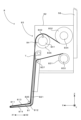
図1は本発明に係る印刷装置を模式的に示す部分断面図であり、図2は図1の印刷装置が備える電気的構成を示すブロック図である。図1および以下の図では、水平方向であるX方向、X方向に直交する水平方向であるY方向および鉛直方向であるZ方向を適宜示すとともに、X方向の一方側X1および他方側X2を適宜示す。ここで、一方側X1と他方側X2とは互いに逆を向く。 Figure 1 is a partial cross-sectional view showing a schematic diagram of a printing device according to the present invention, and Figure 2 is a block diagram showing the electrical configuration of the printing device of Figure 1. In Figure 1 and the following figures, the horizontal X direction, the horizontal Y direction perpendicular to the X direction, and the vertical Z direction are appropriately shown, as well as one side X1 and the other side X2 of the X direction. Here, one side X1 and the other side X2 face in opposite directions.
印刷装置1は、マスクMに下側から対向する基板Bに設けられたランドにはんだSを印刷する。つまり、マスクMにはランドに応じたパターン孔が貫通しており、マスクMの上面Muに供給されたはんだSがマスクMのパターン孔を介して基板Bのランドに印刷される。
The
図2に示すように、印刷装置1は、制御ユニット100を備え、制御ユニット100は、CPU(Central Processing Unit)等のプロセッサで構成された主制御部110と、HDD(Hard Disk Drive)あるいはSSD(Solid State Drive)等の記憶装置で構成された記憶部120とを有する。また、制御ユニット100は、駆動制御部130およびIO制御部140を有し、駆動制御部130およびIO制御部140は主制御部110の指令に応じて、後に説明する各制御を実行する。
As shown in FIG. 2, the
印刷装置1は、基板Bの搬入および搬出を実行する印刷テーブルユニット2を有する。この印刷テーブルユニット2は、水平に配置された印刷テーブル21と、印刷テーブル21をX方向に駆動するX軸駆動部22と、印刷テーブル21をY方向に駆動するY軸駆動部23と、印刷テーブル21をZ方向に駆動するZ軸駆動部24と、印刷テーブル21をR方向に駆動するR軸駆動部25とを有する。ここで、R方向は、Z方向に平行な回転軸を中心とする回転方向である。さらに、印刷テーブルユニット2は、印刷テーブル21から上方へ延設された一対のブラケット26と、一対のブラケット26の上端に取り付けられた一対のコンベア27とを有する。各コンベア27は、Y方向に平行に配置されたベルトコンベアであり、基板Bは各コンベア27の上面で支持される。また、印刷テーブルユニット2は、一対のコンベア27をY方向に回転駆動するコンベア駆動部28を有し、コンベア駆動部28が一対のコンベア27を駆動すると、一対のコンベア27に支持される基板BがY方向に搬送される。
The
駆動制御部130は、各駆動部22~25および28を制御することで、コンベア27によって外部から搬入した基板Bの位置を各駆動部22~25によって調整して、基板Bを作業位置に位置決めする。こうして作業位置に位置決めされた基板Bに対してはんだSが印刷される。さらに、駆動制御部130は、はんだSが印刷された基板Bをコンベア27によって外部に搬出する。
The
また、印刷装置1は、印刷テーブルユニット2の上方にマスククランプ部材3を備える。マスククランプ部材3はマスクMを水平に保持し、印刷テーブルユニット2によって作業位置に位置決めされた基板Bの上面は、マスククランプ部材3に保持されるマスクMの仮面に接触する。
The
この印刷装置1は、マスククランプ部材3に保持されるマスクMを交換するためのマスク交換ユニット4を備える。このマスク交換ユニット4は、マスククランプ部材3の他方側X2に配置されたマスク収納ラック41を有する。マスク収納ラック41は、Z方向に配列された2個のマスク収納スロット411を有し、各マスク収納スロット411にマスクMを収納できる。さらに、マスク交換ユニット4は、マスク収納ラック41をZ方向に昇降させるラック昇降部42を有する。ラック昇降部42は、IO制御部140による制御に応じてマスク収納ラック41を昇降させることで、2個のマスク収納スロット411のうちの一のマスク収納スロット411を、マスククランプ部材3にX方向から対向させる。そして、マスククランプ部材3と、当該マスククランプ部材3に対向するマスク収納スロット411との間でマスクMを移動させることができる。
The
さらに、印刷装置1は作業ユニット5を備える。作業ユニット5は、作業ヘッド51と、作業ヘッド51をX方向に駆動するX軸駆動機構53とを有する。X軸駆動機構53は、X方向に平行に配置されたX軸ボールネジ531と、X軸ボールネジ531を回転駆動するモータであるX軸駆動部532とを有し、X軸ボールネジ531のナットに作業ヘッド51が取り付けられている。このX軸駆動部532は、駆動制御部130による制御に応じてX軸ボールネジ531を回転させることで作業ヘッド51をX方向に駆動する。
The
作業ヘッド51はスキージユニット6を有し、スキージユニット6はY方向に平行に設けられたブレード状のスキージ61を有する。さらに、作業ヘッド51は、スキージユニット6をZ方向に昇降させるZ軸駆動部54と、スキージ61をθ方向に回転させるθ軸駆動部55とを有する。ここで、θ方向は、Y方向に平行な回転軸を中心とする回転方向である。Z軸駆動部54は例えばZ方向に平行に配置されたボールネジあるいはリニアモータといった単軸ロボットにより構成でき、θ軸駆動部55は例えばモータと当該モータの回転をスキージ61に伝達するギア等により構成できる。そして、各駆動部532、54、55は、駆動制御部130の制御に応じて次の印刷動作を実行する。つまり、θ軸駆動部55がマスクMの上面Muに対するスキージ61の接触角度(アタック角)を調整しつつZ軸駆動部54がスキージユニット6を下降させて、スキージ61を所定の圧力(印圧)でマスクMの上面Muに押圧する。続いて、X軸駆動部532がスキージユニット6をX方向に移動させることで、スキージ61がマスクMの上面Muに摺動される。これによって、スキージ61によって押されたはんだSがマスクMのパターンを介して基板Bに印刷される。
The working
また、作業ヘッド51はマスクスライダ7を有する。マスクスライダ7は、Z方向に昇降可能なスライドバー71と、スライドバー71を収容する本体72とを有する。ここの例では、マスクスライダ7はエアシリンダにより構成され、スライドバー71はエアシリンダのロッドであり、本体72はエアシリンダのシリンダである。IO制御部140による制御に応じてマスクスライダ7がスライドバー71を下降させて、マスククランプ部材3に保持されるマスクMにスライドバー71を係合させつつ、X軸駆動部532が駆動制御部130の制御に応じてマスクスライダ7を他方側X2に駆動することで、マスククランプ部材3からマスク収納スロット411にマスクMを移動できる。あるいは、IO制御部140による制御に応じてマスクスライダ7がスライドバー71を下降させてマスク収納スロット411に収納されるマスクMにスライドバー71を係合させつつ、X軸駆動部532が駆動制御部130の指令に応じてマスクスライダ7を一方側X1に駆動することでマスク収納スロット411からマスククランプ部材3にマスクMを移動できる。したがって、これらの動作を組み合わせて行うことで、マスククランプ部材3に保持されるマスクMを交換することができる。
The working
また、作業ヘッド51は距離センサ56を有する。距離センサ56は、上方からマスクMの上面Muに対向して対象物までの距離を検出する。具体的には、距離センサ56は、マスクMの上面MuにおけるはんだSの形状(ロール形状)のX方向への幅を測定するのに用いられる。つまり、駆動制御部130がはんだSの上方で距離センサ56をX方向に駆動しつつ、IO制御部140が距離センサ56の検出値をサンプリングする。こうして、はんだSが距離センサ56によってX方向にスキャンされ、IO制御部140はX方向にはんだSのロール形状、特に幅を取得することができる。なお、はんだSの幅の測定方法はこの例に限られず、例えば上方からはんだSを撮像した画像に基づきはんだSの幅を測定してもよい。
The
さらに、作業ヘッド51は、マスクMからはんだSを掬い上げるスクレーパユニット8と、スクレーパユニット8をZ方向に昇降させるZ軸駆動部58とを有する。このZ軸駆動部58は、Z方向に平行に配置されたエアシリンダ、ボールネジあるいはリニアモータといった単軸ロボットにより構成できる。続いては、図3を併用しつつ、スクレーパユニット8の詳細について説明する。
The
図3はスクレーパユニットの構成を模式的に示す図である。スクレーパユニット8は、マスクMからはんだSを掬い上げるスクレーパ81を有する。スクレーパ81はY方向に平行なブレードである。このスクレーパ81は、X方向の一方側X1を向く先端811と、X方向の他方側X2を向く後端812と、先端811と後端812との間に延設されてZ方向の上側を向く上面813と、先端811と後端812との間に延設されてZ方向の下側を向く下面814とを有する。スクレーパ81の上面813は、先端811から後端812へ向かって上昇するように傾斜する。
Figure 3 is a diagram showing the structure of the scraper unit. The
また、スクレーパユニット8は、スクレーパ81の上方に配置されたハウジング82と、ハウジング82とスクレーパ81の後端812とを接続するフレーム821とを有する。つまり、フレーム821の上端がハウジング82に取り付けられ、フレーム821の下端がスクレーパ81の後端812に取り付けられており、スクレーパ81はフレーム821を介してハウジング82に支持される。
The
このスクレーパユニット8は、紙あるいは布等で構成された帯状のシートTをスクレーパ81の上面813に対して搬送するシート搬送機構83を有する。このシート搬送機構83は、ハウジング82に回転可能に支持された第1駆動ローラ831および第2駆動ローラ832を有する。第1駆動ローラ831および第2駆動ローラ832は、Y方向に平行に配置されており、第1駆動ローラ831は第2駆動ローラ832より下側に位置する。第1駆動ローラ831にはシートTの一端が取り付けられ、第2駆動ローラ832にはシートTの他端が取り付けられている。
The
さらに、スクレーパユニット8は、第1駆動ローラ831を回転駆動するモータである第1シート駆動部833と、第2駆動ローラ832を回転駆動するモータである第2シート駆動部834とを有する。そして、駆動制御部130の制御に応じて、第1シート駆動部833および第2シート駆動部834の一方が選択的に動作する。第1シート駆動部833が第1駆動ローラ831を駆動すると、第1駆動ローラ831がシートTを巻き取って、第2駆動ローラ832から第1駆動ローラ831にシートTがロール・トゥ・ロールで搬送される。また、第2シート駆動部834が第2駆動ローラ832を駆動すると、第2駆動ローラ832がシートTを巻き取って、第1駆動ローラ831から第2駆動ローラ832にシートTがロール・トゥ・ロールで搬送される。
The
これら第1駆動ローラ831および第2駆動ローラ832に対して、スクレーパ81は一方側X1に配置され、第1駆動ローラ831と第2駆動ローラ832との間のシートTに対して、スクレーパ81の先端811が他方側X2から当接する。これによって、シートTは、スクレーパ81の先端811によって他方側X2に折り返され、スクレーパ81の先端811と第2駆動ローラ832との間のシートTは、スクレーパ81の上面813に対向し、スクレーパ81の先端811と第1駆動ローラ831との間のシートTは、スクレーパ81の下面814に対向する。
The
さらに、シート搬送機構83は、フレーム821に取り付けられた不図示のフレームに回転可能に支持されたローラ835を有する。このローラ835は、Y方向に平行に配置され、スクレーパ81の先端811と後端812との間で上側からスクレーパ81の上面813に対向する。したがって、シートTは、スクレーパ81の上面813とローラ835との間に挟まれる。これによって、スクレーパ81の先端811とローラ835との間では、シートTは上面813に沿って搬送される。
Furthermore, the
シート搬送機構83は、ハウジング82に回転可能に支持されたローラ836を有する。このローラ836は、Y方向に平行に配置され、第2駆動ローラ832とローラ835との間でシートTを巻き掛ける。したがって、例えば第2駆動ローラ832から第1駆動ローラ831にシートTを搬送する場合には、第2駆動ローラ832から引き出されたシートTは、ローラ836によって下側に折り曲げられてから、スクレーパ81の上面813とローラ835との間に進入する。
The
シート搬送機構83は、ハウジング82に回転可能に支持されたローラ837を有する。このローラ837は、Y方向に平行に配置され、第1駆動ローラ831とスクレーパ81との間でシートTを巻き掛ける。したがって、例えば第2駆動ローラ832から第1駆動ローラ831にシートTを搬送する場合には、スクレーパ81の下面814を通過したシートTは、ローラ837に向けて上昇してから、第1シート駆動部833に巻き取られる。
The
シート搬送機構83は、ローラ836に対して設けられたエンコーダ84を備える。エンコーダ84は、ローラ836と同軸に設けられてローラ836に伴って回転するエンコーダディスク841を有し、シートTの搬送に従動してローラ836が回転するとエンコーダディスク841の回転位置が変化する。また、シート搬送機構83は、エンコーダディスク841の回転位置を検出するエンコーダセンサ842(例えば光学センサ)を有する。したがって、IO制御部140は、エンコーダセンサ842の検出値に基づき、シートTの搬送位置を確認することができる。
The
このようなスクレーパユニット8では、第1シート駆動部833が第1駆動ローラ831を駆動して第1駆動ローラ831がシートTを巻き取ると、第2駆動ローラ832から引き出されたシートTが、ローラ836によって下側に折り返されて、ローラ835とスクレーパ81の上面813との間に進入する。続いて、シートTは、ローラ835によって一方側X1へ折り返されて、スクレーパ81の上面813に沿って先端811に向かって移動する。スクレーパ81の先端811に到達したシートTは、先端811によって一方側X1から他方側X2へ折り返されて、スクレーパ81の下面814の下側を後端812に向かって移動する。スクレーパ81の後端812に到達したシートTは、ローラ837に向かって上昇して、ローラ837によって他方側X2に折り返されて第1駆動ローラ831に巻き取られる。
In such a
また、第2シート駆動部834が第2駆動ローラ832を駆動して第2駆動ローラ832がシートTを巻き取ると、第1駆動ローラ831から引き出されたシートTが、ローラ837によって下側に折り返されて、スクレーパ81の後端812に向かって下降する。後端812に到達したシートTは、スクレーパ81の下面814の下側を先端811に向かって一方側X1に移動する。先端811に到達したシートTは、先端811によって一方側X1から他方側X2へ折り返されて、スクレーパ81の上面813に沿ってローラ835に向かって移動する。ローラ835に到達したシートTは、ローラ836に向かって上昇して、ローラ836によって他方側X2に折り返されて第2駆動ローラ832に巻き取られる。
When the second
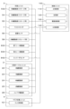
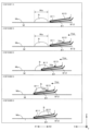
図4は図1の印刷装置で実行される動作の一例を示すフローチャートであり、図5は図4のフローチャートの掬い上げ動作の具体的内容を模式的に示す図であり、図6は図4のフローチャートの下ろし動作の具体的内容を模式的に示す図である。図4のフローチャートの各ステップは、主制御部110の制御に従って実行される。
Figure 4 is a flow chart showing an example of the operation executed by the printing device of Figure 1, Figure 5 is a diagram showing the specific contents of the scooping operation of the flow chart of Figure 4, and Figure 6 is a diagram showing the specific contents of the lowering operation of the flow chart of Figure 4. Each step of the flow chart of Figure 4 is executed according to the control of the
ステップS101では、上述の手順に従って印刷動作が実行される。つまり、スキージ61がマスクMの上面Muに摺動されて、マスクMの上面MuのはんだSがマスクMのパターン孔を介して基板Bに印刷される。ステップS102では、マスクMの上面MuにおけるはんだSのX方向への幅Waが距離センサ56によって計測される。ステップS103では、はんだSを印刷する基板Bの機種が変更されるかが確認される。機種が変更されない場合(ステップS103で「NO」の場合)には、ステップS101、S102が繰り返される一方、機種が変更される場合には、ステップS104~S108が実行される。
In step S101, the printing operation is performed according to the procedure described above. That is, the
ステップS104では、図5に示す掬い上げ動作(ステップS1041~S1045)が実行される。ステップS1041では、駆動制御部130がX軸駆動部532およびZ軸駆動部58を制御することで、マスクM上のはんだSの他方側X2にスクレーパ81を位置させる。このステップS1041では、スクレーパ81は、シートTを介してマスクMの上面Muに当接し、スクレーパ81の先端811はマスクMの上面MuのはんだSに向く。
In step S104, the scooping operation (steps S1041 to S1045) shown in FIG. 5 is performed. In step S1041, the
ステップS1042では、駆動制御部130がX軸駆動部532によるスクレーパ81のX方向の移動と、第2シート駆動部834によるシートTの搬送とを開始する。これによって、スクレーパ81はマスクMに対して一方側X1へ速度Vsaで移動し、シートTはスクレーパ81の上面813に対して速度Vtaで他方側X2へ移動する。ここで、速度Vsaの絶対値と速度Vtaの絶対値とは等しい。こうして、スクレーパ81の先端811がはんだSに向かって移動し、シートTは、スクレーパ81の上面813に沿ってスクレーパ81の先端811から後端812に向かって移動する。
In step S1042, the
この際、駆動制御部130は、IO制御部140が受信したエンコーダセンサ842の出力値に基づき、シートTが移動する速度を検出する。そして、駆動制御部130は、検出したシートTの速度に基づき、スクレーパ81が移動する速度を制御することで、シートTの移動とスクレーパ81の移動とを同期させる。これによって、シートTが速度Vtaで移動するとともにスクレーパ81が速度Vsaで移動する。また、駆動制御部130は、エンコーダセンサ842の出力値に基づき、シートTの移動量(移動距離)を検出する。
At this time, the
こうして、一方側X1に移動するスクレーパ81によってはんだSがマスクMから掬い上げられて、スクレーパ81の上面813に沿って移動するシートTの上にはんだSの他方側X2の端部が乗り上がる(ステップS1043)。さらに、スクレーパ81の移動とシートTとの搬送が継続されて、はんだSがマスクMの上面Muからスクレーパ81の上面813のシートTに移載される(ステップS1044)。はんだSの全体がスクレーパ81の上面813のシートTに乗ると、スクレーパ81の移動とシートTの搬送とが停止される(ステップS1045)。そして、スクレーパ81が上昇して、マスクMから上方へ離間する。なお、駆動制御部130は、シートTの移動を開始してから終了するまでのシートTの移動量である掬い移動量を記憶している。この掬い移動量は、半田Sの全体がシートTの移動に伴ってマスクMの上面Muからスクレーパ81の上面813に移動するのに要する移動量に相当する。そして、駆動制御部130は、エンコーダセンサ842の出力値に基づき検出したシートTの移動量が掬い移動量になると、シートTの移動を停止する(ステップS1045)。
In this way, the
ステップS105では、マスククランプ部材3に保持されるマスクMが交換される。つまり、ステップS101の印刷動作で使用した一のマスクMがマスククランプ部材3からマスク収納ラック41に収納され、マスク収納ラック41に収納されていた他のマスクMがマスク収納ラック41からマスククランプ部材3に引き出されて、マスククランプ部材3に保持される。
In step S105, the mask M held by the
ステップS106では、図6に示す下ろし動作(ステップS1061~S1065)が実行される。ステップS1061では、駆動制御部130がZ軸駆動部58を制御することで、ステップS104ではんだSを掬い上げたスクレーパ81をマスクMの上面Muに当接させる。これによって、上面813のシートTにはんだSが載置されたスクレーパ81がシートTを介してマスクMの上面Muに当接する。
In step S106, the lowering operation (steps S1061 to S1065) shown in FIG. 6 is performed. In step S1061, the
ステップS1062では、駆動制御部130がX軸駆動部532によるスクレーパ81のX方向の移動と、第1シート駆動部833によるシートTの搬送とを開始する。これによって、スクレーパ81はマスクMに対して他方側X2へ速度Vsbで移動し、シートTはスクレーパ81の上面813に対して速度Vtbで一方側X1へ移動する。つまり、シートTは、スクレーパ81の上面813に沿ってスクレーパ81の先端811に向かって移動する。なお、下ろし動作におけるスクレーパ81の速度VsbおよびシートTの速度Vtbの設定方法は後述する。
In step S1062, the
この際、駆動制御部130は、IO制御部140が受信したエンコーダセンサ842の出力値に基づき、シートTが移動する速度を検出する。そして、駆動制御部130は、検出したシートTの速度に基づき、スクレーパ81が移動する速度を制御することで、シートTの移動とスクレーパ81の移動とを同期させる。これによって、シートTが速度Vtbで移動するとともにスクレーパ81が速度Vsbで移動する。また、駆動制御部130は、エンコーダセンサ842の出力値に基づき、シートTの移動量(移動距離)を検出する。
At this time, the
一方側X1に移動するシートTによってはんだSがスクレーパ81の上面813に沿って先端811に向かって移動し(ステップS1063)、はんだSの一方側X1の端部がスクレーパ81からマスクMに下ろされる(ステップS1064)。さらに、スクレーパ81の移動とシートTとの搬送が継続されて、はんだSの全体がスクレーパ81の上面813のシートTからマスクMの上面Muに移載される(ステップS1065)。そして、スクレーパ81が上昇して、マスクMから上方へ離間する。なお、駆動制御部130は、シートTの移動を開始してから終了するまでのシートTの移動量である下ろし移動量を記憶している。この下ろし移動量は、半田Sの全体がシートTの移動に伴ってスクレーパ81の上面813からマスクMの上面Muに移動するのに要する移動量に相当する。そして、駆動制御部130は、エンコーダセンサ842の出力値に基づき検出したシートTの移動量が下ろし移動量になると、シートTの移動を停止する(ステップS1065)。
The solder S moves toward the
ステップS107では、ステップS106の下ろし動作でマスクMの上面Muに戻されたはんだSのX方向への幅Wbが距離センサ56によって計測される。こうして掬い上げ動作(ステップS104)および下ろし動作(ステップS106)の実行前のはんだSの幅Wa(ステップS102)と、これらの動作の実行後のはんだSの幅Wb(ステップS107)とが取得されると、主制御部110が、下ろし動作でのスクレーパ81の速度VsbとシートTの速度Vtbとの関係をこれらの幅Wa、Wbに基づき補正する(ステップS108)。
In step S107, the
つまり、図6の下ろし動作において、スクレーパ81の上面813に沿って先端811に向かって他方側X2へ移動するシートTの速度Vtbに対して、一方側X1に移動するスクレーパ81の速度Vsbが速すぎると、マスクMの上面Muに下ろされたはんだSの幅Wbが、マスクMの上面Muから掬い上げられる前のはんだSの幅Waより広くなる。一方、スクレーパ81の上面813に沿って先端811に向かって他方側X2へ移動するシートTの速度Vtbに対して、一方側X1に移動するスクレーパ81の速度Vsbが遅すぎる、マスクMの上面Muに下ろされたはんだSの幅Wbが、マスクMの上面Muから掬い上げられる前のはんだSの幅Waより狭くなる。したがって、はんだSの幅Waおよび幅Wbの差を抑制するように、下ろし動作でのスクレーパ81の速度VsbとシートTの速度Vtbとの関係が補正される。
6, if the speed Vsb of the
ここでは、次式
Vtb(n+1)=Vtb(n)×(1+((Wb/Wa)-1)×K) …式F1
に従ってシートTの速度Vtbが補正される。ここで、nは補正の回数を示し、Vtb(n)は今回の下ろし動作(つまり、直近に実行した下ろし動作)でのシートTの速度Vtbであり、Vtb(n+1)は次回の下ろし動作でのシートTの速度Vtb(すなわち、補正後の速度Vtb)である。また、Kは0より大きくて1より小さい係数であり、例えば0.5である。係数Kは、補正回数nの増大に応じて速度Vtbを収束させるために設けられており、例えば、式F1に基づく補正を繰り返す実験を行った結果から適当な係数Kを予め設定しておくことができる。
Here, the following formula is used: Vtb(n+1)=Vtb(n)×(1+((Wb/Wa)−1)×K) ...Formula F1
The speed Vtb of the sheet T is corrected according to the formula F1. Here, n indicates the number of corrections, Vtb(n) is the speed Vtb of the sheet T in the current lowering operation (i.e., the most recently executed lowering operation), and Vtb(n+1) is the speed Vtb of the sheet T in the next lowering operation (i.e., the corrected speed Vtb). K is a coefficient greater than 0 and less than 1, for example, 0.5. The coefficient K is provided to converge the speed Vtb as the number of corrections n increases, and an appropriate coefficient K can be set in advance based on the results of an experiment in which correction based on the formula F1 is repeated, for example.
上記の式F1に基づく補正によって、幅Wbが幅Waより広い場合には、シートTの速度Vtbが増大するように当該速度Vtbが補正され、幅Wbが幅Waより狭い場合には、シートTの速度Vtbが減少するように当該速度Vtbが補正され、幅Wbが幅Waと等しい場合には、シートTの速度Vtbは変更されない。なお、下ろし動作でのスクレーパ81の速度Vsbは初期値から変更されずに一定である。
By the correction based on the above formula F1, when the width Wb is wider than the width Wa, the speed Vtb of the sheet T is corrected to increase, when the width Wb is narrower than the width Wa, the speed Vtb of the sheet T is corrected to decrease, and when the width Wb is equal to the width Wa, the speed Vtb of the sheet T is not changed. Note that the speed Vsb of the
こうして、ステップS108でシートTの速度Vtbの補正値Vtb(n+1)が算出されると、ステップS101~S103が実行される。さらに、はんだSを印刷する基板Bの機種が変更される場合(ステップS103で「YES」の場合)には、ステップS104~S108が実行される。この際の下ろし動作(ステップS106)では、シートTは、スクレーパ81の上面813に対して速度Vtb(n+1)で先端811に向かって移動する。
In this way, when the correction value Vtb(n+1) of the speed Vtb of the sheet T is calculated in step S108, steps S101 to S103 are executed. Furthermore, if the model of the board B on which the solder S is printed is changed (if "YES" in step S103), steps S104 to S108 are executed. In this lowering operation (step S106), the sheet T moves toward the
以上に説明する実施形態では、はんだSをマスクMから掬い上げる掬い上げ動作(ステップS104)と、はんだをマスクに下ろす下ろし動作(ステップS106)とがこの順番で実行される。特に下ろし動作(ステップS106)では、先端811が一方側X1を向くスクレーパ81を有するスクレーパユニット8(上げ下ろしユニット)をマスクMに対して他方側X2へ移動させることでスクレーパ81の上面813からマスクMへはんだSが下ろされる。この際、はんだSが載置されたスクレーパ81の上面813のシートTを一方側X1へ移動させることで、スクレーパ81からマスクMにはんだSを確実に下ろすことができる。また、掬い上げ動作(ステップS104)の前のマスクM上のはんだSの幅Wa(第1幅)が取得され、下ろし動作(ステップS106)の後のマスクM上のはんだSの幅Wb(第2幅)が取得される。そして、主制御部110(制御部)は、下ろし動作(ステップS106)でスクレーパ81の上面813のシートTを一方側X1へ移動させる速度Vtb(シート速度)の補正値Vtb(n+1)を、幅Waと幅Wbとに基づき算出する(ステップS108)。そして、補正値の算出(ステップS108)の後の下ろし動作(ステップS106)の実行時には、補正値により速度Vtb(対象速度)を補正した状態で(すなわち、速度Vtb(n+1)で)、スクレーパ81の速度VsbとシートTの速度Vtbとが制御される。つまり、マスクMから掬い上げられる前のはんだSの幅Waと、マスクMに下ろされた後のはんだSの幅Wbとに基づき、下ろし動作(ステップS106)での速度Vsbと速度Vtbとの関係が補正される。その結果、スクレーパ81からマスクMに適切なロール形状ではんだSを下ろすことが可能となっている。
In the embodiment described above, the scooping operation (step S104) of scooping up the solder S from the mask M and the lowering operation (step S106) of lowering the solder onto the mask are performed in this order. In particular, in the lowering operation (step S106), the scraper unit 8 (lifting and lowering unit) having the
また、駆動制御部130(制御部)は、補正値の算出(ステップS108)の後の下ろし動作(ステップS106)では、補正値で速度Vtb(対象速度)を補正した状態で(すなわち、速度Vtb(n+1)で)、スクレーパユニット8の他方側X2への移動と、スクレーパ81の上面813のシートTの一方側X1への移動とを同期させる。かかる構成では、スクレーパ81の移動とシートTの移動とを同期させて、スクレーパ81からマスクMに適切なロール形状ではんだSを下ろすことができる。
In addition, in the lowering operation (step S106) after calculating the correction value (step S108), the drive control unit 130 (control unit) synchronizes the movement of the
また、シート搬送機構83は、シートTの移動速度を検出するエンコーダ84を有する。そして、駆動制御部130(制御部)は、エンコーダ84が検出するシートTの移動速度に基づきマスクMに対するスクレーパユニット8の移動速度を制御することで、スクレーパユニット8の他方側X2への移動と、スクレーパ81の上面813のシートTの一方側X1への移動とを同期させる。このようにシートTの移動速度を検出するエンコーダ84を用いることで、シートTの移動にスクレーパ81の移動を的確に同期させて、スクレーパ81からマスクMに適切なロール形状ではんだSを下ろすことができる。
The
以上に説明したように本実施形態では、印刷装置1が本発明の「印刷装置」の一例に相当し、主制御部110および駆動制御部130が協働して本発明の「制御部」として機能し、マスククランプ部材3が本発明の「マスク保持部」の一例に相当し、X軸駆動機構53が本発明の「ユニット駆動部」の一例に相当し、距離センサ56が本発明の「はんだ幅取得部」の一例に相当し、スクレーパユニット8が本発明の「上げ下ろしユニット」の一例に相当し、スクレーパ81が本発明の「スクレーパ」の一例に相当し、先端811が本発明の「先端」の一例に相当し、上面813が本発明の「上面」の一例に相当し、シート搬送機構83が本発明の「シート駆動部」の一例に相当し、エンコーダ84が本発明の「エンコーダ」の一例に相当し、マスクMが本発明の「マスク」の一例に相当し、シートTが本発明の「シート」の一例に相当し、速度Vsbが本発明の「ユニット速度」の一例に相当し、速度Vtbが本発明の「シート速度」および「対象速度」の一例に相当し、幅Waが本発明の「第1幅」の一例に相当し、幅Wbが本発明の「第2幅」の一例に相当し、X方向が本発明の「所定方向」の一例に相当し、一方側X1が本発明の「一方側」の一例に相当し、他方側X2が本発明の「他方側」の一例に相当し、ステップS104が本発明の「掬い上げ動作」の一例に相当し、ステップS106が本発明の「下ろし動作」の一例に相当する。
As described above, in this embodiment, the
なお、本発明は上記実施形態に限定されるものではなく、その趣旨を逸脱しない限りにおいて上述したものに対して種々の変更を加えることが可能である。例えば、ステップS108において、下ろし動作でのスクレーパ81の速度Vsbの補正値を算出してもよい。この場合、次式
Vsb(n+1)=Vsb(n)×(1+((Wa/Wb)-1)×K) …式F2
に従ってスクレーパ81の速度Vsbが補正される。ここで、Vsb(n)は今回の下ろし動作(つまり、直近に実行した下ろし動作)でのスクレーパ81の速度Vsbであり、Vsb(n+1)は次回の下ろし動作でのスクレーパ81の速度Vsb(すなわち、補正後の速度Vsb)である。式F2中の他のパラメータは上述と同様である。
The present invention is not limited to the above embodiment, and various modifications can be made to the above without departing from the spirit of the present invention. For example, in step S108, a correction value for the speed Vsb of the
Here, Vsb(n) is the speed Vsb of the
上記の式F2に基づく補正によって、幅Wbが幅Waより広い場合には、スクレーパ81の速度Vsbが減少するように当該速度Vsbが補正され、幅Wbが幅Waより狭い場合には、スクレーパ81の速度Vsbが増大するように当該速度Vsbが補正され、幅Wbが幅Waと等しい場合には、スクレーパ81の速度Vtbは変更されない。なお、下ろし動作でのシートTの速度Vtbは初期値から変更されずに一定である。
By the correction based on the above formula F2, when the width Wb is wider than the width Wa, the speed Vsb of the
こうして、ステップS108でスクレーパ81の速度Vsbの補正値Vsb(n+1)が算出されると、ステップS101~S103が実行される。さらに、はんだSを印刷する基板Bの機種が変更される場合(ステップS103で「YES」の場合)には、ステップS104~S108が実行される。この際の下ろし動作(ステップS106)では、スクレーパ81は、マスクMの上面Muに対して速度Vsb(n+1)で他方側X2に向かって移動する。
In this way, once the correction value Vsb(n+1) of the speed Vsb of the
かかる変形例では、掬い上げ動作(ステップS104)の前のマスクM上のはんだSの幅Wa(第1幅)が取得され、下ろし動作(ステップS106)の後のマスクM上のはんだSの幅Wb(第2幅)が取得される。そして、主制御部110(制御部)は、下ろし動作(ステップS106)でスクレーパ81を他方側X2へ移動させる速度Vsb(ユニット速度)の補正値Vsb(n+1)を、幅Waと幅Wbとに基づき算出する(ステップS108)。そして、補正値の算出(ステップS108)の後の下ろし動作(ステップS106)の実行時には、補正値により速度Vsb(対象速度)を補正した状態で(すなわち、速度Vsb(n+1)で)、スクレーパ81の速度VsbとシートTの速度Vtbとが制御される。つまり、マスクMから掬い上げられる前のはんだSの幅Waと、マスクMに下ろされた後のはんだSの幅Wbとに基づき、下ろし動作(ステップS106)での速度Vsbと速度Vtbとの関係が補正される。その結果、スクレーパ81からマスクMに適切なロール形状ではんだSを下ろすことが可能となっている。
In this modified example, the width Wa (first width) of the solder S on the mask M before the scooping operation (step S104) is acquired, and the width Wb (second width) of the solder S on the mask M after the lowering operation (step S106) is acquired. Then, the main control unit 110 (control unit) calculates the correction value Vsb (n+1) of the speed Vsb (unit speed) at which the
ところで、主制御部110は、下ろし動作(ステップS106)において、シートTの速度Vtb(シート速度)がスクレーパ81の速度Vsb(ユニット速度)より遅くなるように、速度Vtbおよび速度Vsbを制御してもよい。例えば、幅Wbが幅Waより広くなるように式F1の(Wb/Wa)の項あるいは式F2の(Wa/Wb)の項を変更して、速度Vtbあるいは速度Vsbを補正するとよい。このような制御は、例えば最初の印刷ではんだSのローリングが不十分な状況に好適となる。つまり、マスクに対してはんだSを比較的広い幅で下ろすことができるため、はんだSのローリング不足に対応しつつ印刷を実行することが可能となる。
The
また、はんだSの幅Waを測定するタイミングは、上記の例に限られない。したがって、はんだSを印刷する基板Bの機種の変更を確認してから(ステップS103で「YES」)、掬い上げ動作(ステップS104)を実行する前に、はんだSの幅Waを測定してもよい。 The timing for measuring the width Wa of the solder S is not limited to the above example. Therefore, the width Wa of the solder S may be measured after confirming a change in the model of the board B on which the solder S is printed ("YES" in step S103) and before performing the scooping operation (step S104).
また、エンコーダ84により検出したシートTの速度に基づきスクレーパ81の移動を制御することは必須ではなく、シートTの移動とスクレーパ81の移動とをそれぞれ独立して制御してもよい。この場合には、エンコーダ84を設ける必要はない。
In addition, it is not essential to control the movement of the
1…印刷装置
110…主制御部(制御部)
130…駆動制御部(制御部)
3…マスククランプ部材(マスク保持部)
53…X軸駆動機構(ユニット駆動部)
56…距離センサ(はんだ幅取得部)
8…スクレーパユニット(上げ下ろしユニット)
81…スクレーパ(スクレーパ)
811…先端
813…上面
83…シート搬送機構(シート駆動部)
84…エンコーダ
M…マスク
T…シート
Vtb…速度(シート速度、対象速度)
Vsb…速度(ユニット速度、対象速度)
Wa…幅Wa(第1幅)
Wb…幅Wb(第2幅)
X…X方向(所定方向)
X1…一方側
X2…他方側
S104…掬い上げ動作
S106…下ろし動作
1...
130: Drive control unit (control unit)
3...Mask clamp member (mask holding portion)
53...X-axis drive mechanism (unit drive part)
56...Distance sensor (solder width acquisition unit)
8...Scraper unit (lifting/lowering unit)
81...scraper (scraper)
811: leading end 813: upper surface 83: sheet transport mechanism (sheet drive unit)
84...Encoder M...Mask T...Sheet Vtb...Speed (sheet speed, target speed)
Vsb: Speed (unit speed, target speed)
Wa: Width Wa (first width)
Wb…Width Wb (second width)
X...X direction (predetermined direction)
X1: One side X2: Other side S104: Scooping up operation S106: Lowering operation
Claims (5)
マスクを保持するマスク保持部と、
前記マスクに対して前記上げ下ろしユニットを前記所定方向に駆動するユニット駆動部と、
前記ユニット駆動部によって前記上げ下ろしユニットを前記マスクに対して移動させることで前記マスクから前記スクレーパにはんだを掬い上げて前記スクレーパの前記上面の前記シートに載置する掬い上げ動作と、前記ユニット駆動部によって前記上げ下ろしユニットを前記マスクに対して前記他方側へ移動させることで前記スクレーパから前記マスクに前記はんだを下ろす下ろし動作とを順番に実行する制御部と、
前記掬い上げ動作の前の前記マスク上の前記はんだの幅を第1幅として取得し、前記下ろし動作の後の前記マスク上の前記はんだの幅を第2幅として取得するはんだ幅取得部と
を備え、
前記上げ下ろしユニットは、前記下ろし動作において、前記はんだが載置された前記スクレーパの前記上面の前記シートを前記シート駆動部によって前記一方側へ移動させ、
前記制御部は、前記下ろし動作で前記上げ下ろしユニットを前記他方側へ移動させるユニット速度と、前記下ろし動作で前記スクレーパの前記上面の前記シートを前記一方側へ移動させるシート速度との少なくとも一方の対象速度の補正値を前記第1幅と前記第2幅とに基づき算出し、前記補正値の算出後の前記下ろし動作では、前記補正値により前記対象速度を補正した状態で前記ユニット速度と前記シート速度とを制御する印刷装置。 a lifting/lowering unit including a scraper having a tip facing one side in a predetermined direction, a sheet provided along an upper surface of the scraper, and a sheet driving unit that drives the sheet folded back to the underside of the scraper at the tip of the scraper to the other side opposite to the one side, thereby moving the sheet along the upper surface of the scraper to the one side;
A mask holder that holds a mask;
a unit driving section that drives the lifting/lowering unit in the predetermined direction relative to the mask;
a control unit that sequentially executes a scooping operation in which the lifting/lowering unit is moved relative to the mask by the unit drive unit to scoop up the solder from the mask onto the scraper and place it on the sheet on the upper surface of the scraper, and a lowering operation in which the lifting/lowering unit is moved to the other side relative to the mask by the unit drive unit to lower the solder from the scraper onto the mask;
a solder width acquisition unit that acquires a width of the solder on the mask before the scooping operation as a first width and acquires a width of the solder on the mask after the lowering operation as a second width,
In the lowering operation, the lifting/lowering unit moves the sheet on the upper surface of the scraper on which the solder is placed to the one side by the sheet driving unit,
The control unit calculates a correction value for at least one of the target speeds, namely, a unit speed that moves the lifting/lowering unit to the other side during the lowering operation, and a sheet speed that moves the sheet on the upper surface of the scraper to the one side during the lowering operation, based on the first width and the second width, and during the lowering operation after calculating the correction value, controls the unit speed and the sheet speed with the target speed corrected by the correction value.
前記制御部は、前記エンコーダが検出する前記シートの移動速度に基づき前記マスクに対する前記上げ下ろしユニットの移動速度を制御することで、前記上げ下ろしユニットの前記他方側への移動と、前記スクレーパの前記上面の前記シートの前記一方側への移動とを同期させる請求項2に記載の印刷装置。 the sheet driving unit has an encoder for detecting a moving speed of the sheet,
The printing device described in claim 2, wherein the control unit synchronizes the movement of the lifting/lowering unit to the other side and the movement of the upper surface of the scraper to the one side of the sheet by controlling the movement speed of the lifting/lowering unit relative to the mask based on the movement speed of the sheet detected by the encoder.
所定方向の一方側を向く先端を有するスクレーパと、前記スクレーパの上面に沿って設けられたシートと、前記スクレーパの前記先端で前記スクレーパの下側に折り返された前記シートを前記一方側と逆の他方側に駆動することで前記スクレーパの前記上面に沿って前記シートを前記一方側に移動させるシート駆動部とを有する上げ下ろしユニットを、前記マスクに対して移動させることで前記マスクから前記スクレーパに前記はんだを掬い上げて前記スクレーパの前記上面の前記シートに載置する掬い上げ動作を実行する工程と、
前記上げ下ろしユニットを前記マスクに対して前記他方側へ移動させることで前記スクレーパから前記マスクへ前記はんだを下ろす下ろし動作を実行する工程と、
前記マスク上の前記はんだの幅を第2幅として取得する工程と、
を備え、
前記下ろし動作では、前記上げ下ろしユニットは、前記はんだが載置された前記スクレーパの前記上面の前記シートを前記シート駆動部によって前記一方側へ移動させ、
前記下ろし動作で前記上げ下ろしユニットを前記他方側へ移動させるユニット速度と、前記下ろし動作で前記スクレーパの前記上面の前記シートを前記一方側へ移動させるシート速度との少なくとも一方の対象速度の補正値を前記第1幅と前記第2幅とに基づき算出し、前記補正値の算出後の前記下ろし動作の実行時には、前記補正値により前記対象速度を補正した状態で前記ユニット速度と前記シート速度とを制御するはんだ下ろし幅の制御方法。
obtaining a width of the solder on the mask as a first width;
a step of performing a scooping operation of scooping up the solder from the mask onto the scraper and placing it on the sheet on the upper surface of the scraper by moving a lifting/lowering unit having a scraper with a tip facing one side in a predetermined direction, a sheet provided along an upper surface of the scraper, and a sheet driving unit that drives the sheet folded back to the underside of the scraper at the tip of the scraper to the other side opposite to the one side, thereby moving the sheet along the upper surface of the scraper to the one side, relative to the mask;
a step of performing a lowering operation of lowering the solder from the scraper to the mask by moving the lifting/lowering unit to the other side relative to the mask;
obtaining a width of the solder on the mask as a second width;
Equipped with
In the lowering operation, the lifting/lowering unit moves the sheet on the upper surface of the scraper on which the solder is placed to the one side by the sheet driving unit,
A method for controlling a soldering width, comprising: calculating a correction value for at least one of a target speed, which is a unit speed that moves the lifting/lowering unit to the other side during the lowering operation, and a sheet speed that moves the sheet on the upper surface of the scraper to the one side during the lowering operation, based on the first width and the second width; and when the lowering operation is performed after calculating the correction value, controlling the unit speed and the sheet speed with the target speed corrected by the correction value.
Priority Applications (1)
| Application Number | Priority Date | Filing Date | Title |
|---|---|---|---|
| JP2021186108A JP7608317B2 (en) | 2021-11-16 | 2021-11-16 | Printing device and method for controlling soldering width |
Applications Claiming Priority (1)
| Application Number | Priority Date | Filing Date | Title |
|---|---|---|---|
| JP2021186108A JP7608317B2 (en) | 2021-11-16 | 2021-11-16 | Printing device and method for controlling soldering width |
Publications (2)
| Publication Number | Publication Date |
|---|---|
| JP2023073571A JP2023073571A (en) | 2023-05-26 |
| JP7608317B2 true JP7608317B2 (en) | 2025-01-06 |
Family
ID=86425621
Family Applications (1)
| Application Number | Title | Priority Date | Filing Date |
|---|---|---|---|
| JP2021186108A Active JP7608317B2 (en) | 2021-11-16 | 2021-11-16 | Printing device and method for controlling soldering width |
Country Status (1)
| Country | Link |
|---|---|
| JP (1) | JP7608317B2 (en) |
Citations (4)
| Publication number | Priority date | Publication date | Assignee | Title |
|---|---|---|---|---|
| US20070272100A1 (en) | 2006-05-26 | 2007-11-29 | Atma Champ Enterprise Corporation | Ink residue lifting and transfer mechanism for screen printing machine |
| WO2019234820A1 (en) | 2018-06-05 | 2019-12-12 | ヤマハ発動機株式会社 | Printing device |
| WO2020137901A1 (en) | 2018-12-28 | 2020-07-02 | パナソニックIpマネジメント株式会社 | Solder paste recovery device and screen printing device |
| JP2020157668A (en) | 2019-03-27 | 2020-10-01 | 島根県 | Image relay device, image forming device, and image forming method |
Family Cites Families (2)
| Publication number | Priority date | Publication date | Assignee | Title |
|---|---|---|---|---|
| JP2932576B2 (en) * | 1990-03-07 | 1999-08-09 | 松下電器産業株式会社 | Screen printing equipment |
| KR101993692B1 (en) * | 2017-11-09 | 2019-06-26 | 주식회사이에스이 | Device for collecting solder cream of metal mask and method for collecting the same |
-
2021
- 2021-11-16 JP JP2021186108A patent/JP7608317B2/en active Active
Patent Citations (4)
| Publication number | Priority date | Publication date | Assignee | Title |
|---|---|---|---|---|
| US20070272100A1 (en) | 2006-05-26 | 2007-11-29 | Atma Champ Enterprise Corporation | Ink residue lifting and transfer mechanism for screen printing machine |
| WO2019234820A1 (en) | 2018-06-05 | 2019-12-12 | ヤマハ発動機株式会社 | Printing device |
| WO2020137901A1 (en) | 2018-12-28 | 2020-07-02 | パナソニックIpマネジメント株式会社 | Solder paste recovery device and screen printing device |
| JP2020157668A (en) | 2019-03-27 | 2020-10-01 | 島根県 | Image relay device, image forming device, and image forming method |
Also Published As
| Publication number | Publication date |
|---|---|
| JP2023073571A (en) | 2023-05-26 |
Similar Documents
| Publication | Publication Date | Title |
|---|---|---|
| JP4185960B2 (en) | Working device and working method for circuit board | |
| CN114714756B (en) | A fully automatic solder paste printer for flexible circuit tape | |
| JP5172007B1 (en) | Printing method and printing apparatus | |
| US10889103B2 (en) | Screen printer and screen printing method | |
| US6964093B2 (en) | System for mounting electronic device | |
| CN1982056B (en) | Screen printing device | |
| JP6622500B2 (en) | Transport device | |
| JP2011189668A (en) | Mask cleaning apparatus, screen printing machine, mask cleaning method, and screen printing method | |
| WO2018127966A1 (en) | Screen printer | |
| JP7608317B2 (en) | Printing device and method for controlling soldering width | |
| JP3554615B2 (en) | Electronic component mounting device | |
| CN112105504A (en) | Printing device | |
| JP2011189669A (en) | Detector for advancing quantity of paper member, screen printing machine, method for detecting advancing quantity of paper member, and screen printing method | |
| JP3545108B2 (en) | Electronic component automatic mounting device and mounting method | |
| JP5062198B2 (en) | Screen printing machine and screen printing method | |
| JP3991795B2 (en) | Screen printing machine | |
| JP4419749B2 (en) | Screen printing method and screen printing apparatus | |
| JP7002181B2 (en) | Screen printing machine | |
| JP4858520B2 (en) | Screen printing machine and screen printing method | |
| JP6892512B2 (en) | Screen printing machine | |
| JP2011143549A (en) | Screen printing machine and method of detecting foreign matter in screen printing machine | |
| CN113320282B (en) | Printing pressure control device and printing pressure control method | |
| CN108290408B (en) | Solder printer and method for controlling solder printer | |
| JP2001129962A (en) | Screen printing method and screen printing apparatus | |
| CN103619593B (en) | Screen printing apparatus |
Legal Events
| Date | Code | Title | Description |
|---|---|---|---|
| A621 | Written request for application examination |
Free format text: JAPANESE INTERMEDIATE CODE: A621 Effective date: 20240404 |
|
| A977 | Report on retrieval |
Free format text: JAPANESE INTERMEDIATE CODE: A971007 Effective date: 20241120 |
|
| TRDD | Decision of grant or rejection written | ||
| A01 | Written decision to grant a patent or to grant a registration (utility model) |
Free format text: JAPANESE INTERMEDIATE CODE: A01 Effective date: 20241217 |
|
| A61 | First payment of annual fees (during grant procedure) |
Free format text: JAPANESE INTERMEDIATE CODE: A61 Effective date: 20241218 |
|
| R150 | Certificate of patent or registration of utility model |
Ref document number: 7608317 Country of ref document: JP Free format text: JAPANESE INTERMEDIATE CODE: R150 |