JP7606552B2 - Transport robot - Google Patents
Transport robot Download PDFInfo
- Publication number
- JP7606552B2 JP7606552B2 JP2023027803A JP2023027803A JP7606552B2 JP 7606552 B2 JP7606552 B2 JP 7606552B2 JP 2023027803 A JP2023027803 A JP 2023027803A JP 2023027803 A JP2023027803 A JP 2023027803A JP 7606552 B2 JP7606552 B2 JP 7606552B2
- Authority
- JP
- Japan
- Prior art keywords
- cargo
- box
- cargo box
- shelf
- component
- Prior art date
- Legal status (The legal status is an assumption and is not a legal conclusion. Google has not performed a legal analysis and makes no representation as to the accuracy of the status listed.)
- Active
Links
Images


Classifications
-
- B—PERFORMING OPERATIONS; TRANSPORTING
- B65—CONVEYING; PACKING; STORING; HANDLING THIN OR FILAMENTARY MATERIAL
- B65G—TRANSPORT OR STORAGE DEVICES, e.g. CONVEYORS FOR LOADING OR TIPPING, SHOP CONVEYOR SYSTEMS OR PNEUMATIC TUBE CONVEYORS
- B65G1/00—Storing articles, individually or in orderly arrangement, in warehouses or magazines
- B65G1/02—Storage devices
- B65G1/04—Storage devices mechanical
- B65G1/137—Storage devices mechanical with arrangements or automatic control means for selecting which articles are to be removed
- B65G1/1373—Storage devices mechanical with arrangements or automatic control means for selecting which articles are to be removed for fulfilling orders in warehouses
- B65G1/1375—Storage devices mechanical with arrangements or automatic control means for selecting which articles are to be removed for fulfilling orders in warehouses the orders being assembled on a commissioning stacker-crane or truck
-
- B—PERFORMING OPERATIONS; TRANSPORTING
- B65—CONVEYING; PACKING; STORING; HANDLING THIN OR FILAMENTARY MATERIAL
- B65G—TRANSPORT OR STORAGE DEVICES, e.g. CONVEYORS FOR LOADING OR TIPPING, SHOP CONVEYOR SYSTEMS OR PNEUMATIC TUBE CONVEYORS
- B65G1/00—Storing articles, individually or in orderly arrangement, in warehouses or magazines
- B65G1/02—Storage devices
- B65G1/04—Storage devices mechanical
- B65G1/0407—Storage devices mechanical using stacker cranes
- B65G1/0435—Storage devices mechanical using stacker cranes with pulling or pushing means on either stacking crane or stacking area
-
- B—PERFORMING OPERATIONS; TRANSPORTING
- B25—HAND TOOLS; PORTABLE POWER-DRIVEN TOOLS; MANIPULATORS
- B25J—MANIPULATORS; CHAMBERS PROVIDED WITH MANIPULATION DEVICES
- B25J9/00—Program-controlled manipulators
- B25J9/16—Program controls
- B25J9/1628—Program controls characterised by the control loop
- B25J9/1653—Program controls characterised by the control loop parameters identification, estimation, stiffness, accuracy, error analysis
-
- B—PERFORMING OPERATIONS; TRANSPORTING
- B25—HAND TOOLS; PORTABLE POWER-DRIVEN TOOLS; MANIPULATORS
- B25J—MANIPULATORS; CHAMBERS PROVIDED WITH MANIPULATION DEVICES
- B25J9/00—Program-controlled manipulators
- B25J9/16—Program controls
- B25J9/1656—Program controls characterised by programming, planning systems for manipulators
- B25J9/1664—Program controls characterised by programming, planning systems for manipulators characterised by motion, path, trajectory planning
-
- B—PERFORMING OPERATIONS; TRANSPORTING
- B25—HAND TOOLS; PORTABLE POWER-DRIVEN TOOLS; MANIPULATORS
- B25J—MANIPULATORS; CHAMBERS PROVIDED WITH MANIPULATION DEVICES
- B25J9/00—Program-controlled manipulators
- B25J9/16—Program controls
- B25J9/1679—Program controls characterised by the tasks executed
-
- B—PERFORMING OPERATIONS; TRANSPORTING
- B25—HAND TOOLS; PORTABLE POWER-DRIVEN TOOLS; MANIPULATORS
- B25J—MANIPULATORS; CHAMBERS PROVIDED WITH MANIPULATION DEVICES
- B25J9/00—Program-controlled manipulators
- B25J9/16—Program controls
- B25J9/1694—Program controls characterised by use of sensors other than normal servo-feedback from position, speed or acceleration sensors, perception control, multi-sensor controlled systems, sensor fusion
- B25J9/1697—Vision controlled systems
-
- G—PHYSICS
- G06—COMPUTING OR CALCULATING; COUNTING
- G06Q—INFORMATION AND COMMUNICATION TECHNOLOGY [ICT] SPECIALLY ADAPTED FOR ADMINISTRATIVE, COMMERCIAL, FINANCIAL, MANAGERIAL OR SUPERVISORY PURPOSES; SYSTEMS OR METHODS SPECIALLY ADAPTED FOR ADMINISTRATIVE, COMMERCIAL, FINANCIAL, MANAGERIAL OR SUPERVISORY PURPOSES, NOT OTHERWISE PROVIDED FOR
- G06Q10/00—Administration; Management
- G06Q10/06—Resources, workflows, human or project management; Enterprise or organisation planning; Enterprise or organisation modelling
-
- G—PHYSICS
- G06—COMPUTING OR CALCULATING; COUNTING
- G06Q—INFORMATION AND COMMUNICATION TECHNOLOGY [ICT] SPECIALLY ADAPTED FOR ADMINISTRATIVE, COMMERCIAL, FINANCIAL, MANAGERIAL OR SUPERVISORY PURPOSES; SYSTEMS OR METHODS SPECIALLY ADAPTED FOR ADMINISTRATIVE, COMMERCIAL, FINANCIAL, MANAGERIAL OR SUPERVISORY PURPOSES, NOT OTHERWISE PROVIDED FOR
- G06Q10/00—Administration; Management
- G06Q10/08—Logistics, e.g. warehousing, loading or distribution; Inventory or stock management
-
- B—PERFORMING OPERATIONS; TRANSPORTING
- B65—CONVEYING; PACKING; STORING; HANDLING THIN OR FILAMENTARY MATERIAL
- B65G—TRANSPORT OR STORAGE DEVICES, e.g. CONVEYORS FOR LOADING OR TIPPING, SHOP CONVEYOR SYSTEMS OR PNEUMATIC TUBE CONVEYORS
- B65G1/00—Storing articles, individually or in orderly arrangement, in warehouses or magazines
- B65G1/02—Storage devices
- B65G1/04—Storage devices mechanical
- B65G1/0492—Storage devices mechanical with cars adapted to travel in storage aisles
-
- B—PERFORMING OPERATIONS; TRANSPORTING
- B65—CONVEYING; PACKING; STORING; HANDLING THIN OR FILAMENTARY MATERIAL
- B65G—TRANSPORT OR STORAGE DEVICES, e.g. CONVEYORS FOR LOADING OR TIPPING, SHOP CONVEYOR SYSTEMS OR PNEUMATIC TUBE CONVEYORS
- B65G2201/00—Indexing codes relating to handling devices, e.g. conveyors, characterised by the type of product or load being conveyed or handled
- B65G2201/02—Articles
- B65G2201/0235—Containers
- B65G2201/0258—Trays, totes or bins
-
- B—PERFORMING OPERATIONS; TRANSPORTING
- B65—CONVEYING; PACKING; STORING; HANDLING THIN OR FILAMENTARY MATERIAL
- B65G—TRANSPORT OR STORAGE DEVICES, e.g. CONVEYORS FOR LOADING OR TIPPING, SHOP CONVEYOR SYSTEMS OR PNEUMATIC TUBE CONVEYORS
- B65G2203/00—Indexing code relating to control or detection of the articles or the load carriers during conveying
- B65G2203/02—Control or detection
- B65G2203/0208—Control or detection relating to the transported articles
- B65G2203/0233—Position of the article
-
- B—PERFORMING OPERATIONS; TRANSPORTING
- B65—CONVEYING; PACKING; STORING; HANDLING THIN OR FILAMENTARY MATERIAL
- B65G—TRANSPORT OR STORAGE DEVICES, e.g. CONVEYORS FOR LOADING OR TIPPING, SHOP CONVEYOR SYSTEMS OR PNEUMATIC TUBE CONVEYORS
- B65G2203/00—Indexing code relating to control or detection of the articles or the load carriers during conveying
- B65G2203/02—Control or detection
- B65G2203/0208—Control or detection relating to the transported articles
- B65G2203/0241—Quantity of articles
-
- B—PERFORMING OPERATIONS; TRANSPORTING
- B65—CONVEYING; PACKING; STORING; HANDLING THIN OR FILAMENTARY MATERIAL
- B65G—TRANSPORT OR STORAGE DEVICES, e.g. CONVEYORS FOR LOADING OR TIPPING, SHOP CONVEYOR SYSTEMS OR PNEUMATIC TUBE CONVEYORS
- B65G2203/00—Indexing code relating to control or detection of the articles or the load carriers during conveying
- B65G2203/02—Control or detection
- B65G2203/0208—Control or detection relating to the transported articles
- B65G2203/0258—Weight of the article
-
- B—PERFORMING OPERATIONS; TRANSPORTING
- B65—CONVEYING; PACKING; STORING; HANDLING THIN OR FILAMENTARY MATERIAL
- B65G—TRANSPORT OR STORAGE DEVICES, e.g. CONVEYORS FOR LOADING OR TIPPING, SHOP CONVEYOR SYSTEMS OR PNEUMATIC TUBE CONVEYORS
- B65G2203/00—Indexing code relating to control or detection of the articles or the load carriers during conveying
- B65G2203/04—Detection means
- B65G2203/041—Camera
-
- G—PHYSICS
- G05—CONTROLLING; REGULATING
- G05B—CONTROL OR REGULATING SYSTEMS IN GENERAL; FUNCTIONAL ELEMENTS OF SUCH SYSTEMS; MONITORING OR TESTING ARRANGEMENTS FOR SUCH SYSTEMS OR ELEMENTS
- G05B2219/00—Program-control systems
- G05B2219/30—Nc systems
- G05B2219/45—Nc applications
- G05B2219/45056—Handling cases, boxes
Landscapes
- Engineering & Computer Science (AREA)
- Mechanical Engineering (AREA)
- Business, Economics & Management (AREA)
- Robotics (AREA)
- Economics (AREA)
- Human Resources & Organizations (AREA)
- Strategic Management (AREA)
- Entrepreneurship & Innovation (AREA)
- Theoretical Computer Science (AREA)
- Operations Research (AREA)
- Tourism & Hospitality (AREA)
- Physics & Mathematics (AREA)
- General Business, Economics & Management (AREA)
- General Physics & Mathematics (AREA)
- Marketing (AREA)
- Quality & Reliability (AREA)
- Development Economics (AREA)
- Educational Administration (AREA)
- Game Theory and Decision Science (AREA)
- Warehouses Or Storage Devices (AREA)
- Accounting & Taxation (AREA)
- Finance (AREA)
Description
本願は、知能倉庫分野に関し、特に、運搬ロボットに関する。 This application relates to the field of intelligent warehouses, and in particular to transport robots.
知能倉庫は物流過程の一環であり、知能倉庫の応用は貨物倉庫管理の各部分のデータ入力の速度と正確さを確保するとともに、企業が適時に在庫の真実データを正確に把握し、企業在庫を合理的に保持し、制御することを確保する。科学的なコードにより、在庫品のロット、貯蔵寿命なども簡単に管理できる。SNHGESシステムの倉庫位置管理機能を利用して、更に適時にすべての在庫品の現在位置を把握でき、倉庫管理の仕事効率を高めることに役立つ。 Intelligent warehousing is part of the logistics process. The application of intelligent warehousing not only ensures the speed and accuracy of data entry in all parts of cargo warehousing management, but also ensures that enterprises can accurately grasp the true data of inventory in a timely manner, and rationally maintain and control enterprise inventory. With scientific coding, inventory lots, storage life, etc. can also be easily managed. By using the warehouse location management function of the SNHGES system, the current location of all inventory items can be grasped in a timely manner, which helps to improve the work efficiency of warehouse management.
運搬ロボットは知能倉庫で重要な役割を果たしている。運搬ロボットは、指示を受けて指定された位置に貨物をピックアップして配置し、運搬することができるため、倉庫で貨物の運搬効率を高める。 Transport robots play an important role in intelligent warehouses. Transport robots can pick up, place, and transport cargo at designated locations according to instructions, thus improving the efficiency of cargo transportation in warehouses.
電子商取引とネットショッピングの台頭と発展に伴い、貨物の倉庫物流の知能化に大きな発展チャンスをもたらし、ここ数年来、運搬ロボットに基づいて貨物を運搬する技術はますます成熟している。 With the rise and development of e-commerce and online shopping, it has brought great development opportunities to the intelligentization of cargo warehouse logistics, and in recent years, the technology of cargo transportation based on transport robots has become increasingly mature.
本願の実施例は、以下の技術的解決手段を提供する。 The embodiments of the present application provide the following technical solutions:
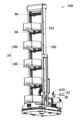
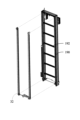
運搬ロボットを提供し、前記運搬ロボットは、立てブラケットと、貨物箱を格納するためのパレットと、立てブラケットに取り付けられる運搬システムと、を含み、前記パレットは前記運搬システムに取り付けられ、前記運搬システムは、貨物箱を倉庫棚と前記パレットのうちの1つから取り出して、もう1つに格納するために使用され、及び/又は前記パレットに格納された貨物箱から貨物を取り出すために使用される。 A transport robot is provided, the transport robot including a standing bracket, a pallet for storing cargo boxes, and a transport system attached to the standing bracket, the pallet being attached to the transport system, the transport system being used to remove cargo boxes from one of a warehouse shelf and the pallet and store them in the other, and/or to remove cargo from the cargo boxes stored on the pallet.
選択的に、前記運搬ロボットはさらに、保管棚を含み、
前記保管棚は貨物箱を格納するために使用され、
前記運搬システムは、貨物箱を前記保管棚と前記パレットのうちの1つから取り出して、もう1つに格納するためにさらに使用され、及び/又はさらに前記保管棚に格納された貨物箱から貨物を取り出して、前記パレットに格納された貨物箱に格納するために使用され、及び/又はさらに前記パレットに格納された貨物箱から貨物を取り出して、前記保管棚に格納された貨物箱に格納するために使用される。
Optionally, the transport robot further includes a storage shelf;
The storage shelf is used to store cargo boxes;
The transport system is further used to remove cargo boxes from one of the storage shelves and the pallets and store them in the other, and/or is further used to remove cargo from cargo boxes stored in the storage shelves and store them in cargo boxes stored on the pallets, and/or is further used to remove cargo from cargo boxes stored on the pallets and store them in cargo boxes stored in the storage shelves.
選択的に、前記運搬システムは、フォークと貨物転送コンポーネントを含み、前記フォークは前記立てブラケットによってサポートされ、前記パレットはフォークに取り付けられ、前記フォークは、貨物箱を倉庫棚と前記パレットのうちの1つから取り出して、もう1つに格納するために使用され、及び/又は前記保管棚と前記パレットのうちの1つから取り出して、もう1つに格納するために使用され、前記貨物転送コンポーネントは前記フォークに取り付けられ、前記貨物転送コンポーネントは、前記パレットに格納された貨物箱と前記保管棚に格納された貨物箱のうちの1つから貨物を取り出して、もう1つに格納するために使用され、前記フォークは取り付けプラットフォームを含み、前記パレットと前記貨物転送コンポーネントは、いずれも前記取り付けプラットフォームに取り付けられる。 Optionally, the transport system includes a fork and a cargo transfer component, the fork is supported by the upright bracket, the pallet is attached to the fork, the fork is used to remove cargo boxes from one of the storage shelf and the pallet and store them in another, and/or the storage shelf and the pallet and store them in another, the cargo transfer component is attached to the fork, the cargo transfer component is used to remove cargo boxes from one of the cargo boxes stored on the pallet and the cargo boxes stored on the storage shelf and store them in another, the fork includes a mounting platform, and both the pallet and the cargo transfer component are attached to the mounting platform.
選択的に、前記運搬システムはフォークと貨物転送コンポーネントを含み、前記フォークは前記立てブラケットによってサポートされ、前記パレットは前記フォークに取り付けられ、前記フォークは、貨物箱を倉庫棚と前記パレットのうちの1つから取り出して、もう1つに格納するために使用され、及び/又は前記保管棚と前記パレットのうちの1つから取り出して、もう1つに格納するために使用され、前記貨物転送コンポーネントは前記立てブラケットに取り付けられ、前記貨物転送コンポーネントは、前記パレットに格納された貨物箱と前記保管棚に格納された貨物箱のうちの1つから貨物を取り出して、もう1つに格納するために使用され、前記フォークは取り付けプラットフォームを含み、前記パレットは前記取り付けプラットフォームに取り付けられる。 Optionally, the transport system includes a fork and a cargo transfer component, the fork is supported by the standing bracket, the pallet is attached to the fork, the fork is used to remove cargo boxes from one of the warehouse shelf and the pallet and store them in another, and/or from one of the storage shelf and the pallet and store them in another, the cargo transfer component is attached to the standing bracket, the cargo transfer component is used to remove cargo boxes from one of the cargo boxes stored on the pallet and the cargo boxes stored in the storage shelf and store them in another, the fork includes a mounting platform, and the pallet is attached to the mounting platform.
選択的に、前記立てブラケットは昇降プラットフォームを含み、前記昇降プラットフォームは垂直方向に沿って移動することができ、前記昇降プラットフォームには前記貨物転送コンポーネントが取り付けられる。 Optionally, the standing bracket includes a lifting platform that is movable along a vertical direction and to which the cargo transfer component is attached.
選択的に、前記貨物転送コンポーネントは多次元機械関節と末端実行装置を含み、前記末端実行装置は前記多次元機械関節に取り付けられ、前記多次元機械関節は前記末端実行装置の多角度回転及び多方向移動を駆動するために使用され、前記末端実行装置は貨物をつかむために使用される。 Optionally, the cargo transfer component includes a multi-dimensional mechanical joint and an end execution device, the end execution device is attached to the multi-dimensional mechanical joint, the multi-dimensional mechanical joint is used to drive multi-angle rotation and multi-directional movement of the end execution device, and the end execution device is used to grasp the cargo.
選択的に、前記末端実行装置は、吸盤装置であり、貨物を吸着するために使用される。 Optionally, the end effector device is a suction cup device and is used to attract cargo.
選択的に、前記運搬ロボットは第2の貨物認識装置を含み、前記第2の貨物認識装置は、前記多次元機械関節に取り付けられ、前記保管棚と前記パレットに格納された貨物箱内の貨物及び/又は前記貨物転送コンポーネントによって取り出された貨物を認識するために使用され、前記多次元機械関節は、前記第2の貨物認識装置及び前記末端実行装置を駆動して、多角度転送及び多方向移動を一緒に実行するために使用される。 Optionally, the transport robot includes a second cargo recognition device, which is attached to the multi-dimensional mechanical joint and is used to recognize cargo in cargo boxes stored on the storage shelves and on the pallets and/or cargo retrieved by the cargo transfer component, and the multi-dimensional mechanical joint is used to drive the second cargo recognition device and the end execution device to perform multi-angle transfer and multi-directional movement together.
選択的に、前記運搬ロボットは貨物箱認識コンポーネントをさらに含み、前記貨物箱認識コンポーネントは、前記取り付けプラットフォームに取り付けられ、貨物箱を認識するために使用される。 Optionally, the transport robot further includes a cargo box recognition component, the cargo box recognition component being mounted on the mounting platform and used to recognize the cargo box.
選択的に、前記貨物箱認識コンポーネントは撮影装置を含む。 Optionally, the cargo box recognition component includes a camera.
選択的に、前記フォークは、伸縮アーム、固定プッシュロッド及び可動プッシュロッドを含み、前記伸縮アームは水平方向に伸び出されることができ、前記固定プッシュロッド及び前記可動プッシュロッドはいずれも前記伸縮アームに取り付けられ、そして前記伸縮アームが伸び出されるときに、前記固定プッシュロッド及び前記可動プッシュロッドは一緒に伸び出され、前記固定プッシュロッドは、前記伸縮アームが伸び出されるときに貨物箱を押すために使用され、前記可動プッシュロッドは前記伸縮アームに後退されることができ、前記可動プッシュロッドは前記伸縮アームが後退されるときに貨物箱を引くために使用される。 Optionally, the fork includes a telescopic arm, a fixed push rod and a movable push rod, the telescopic arm can be extended horizontally, the fixed push rod and the movable push rod are both attached to the telescopic arm, and when the telescopic arm is extended, the fixed push rod and the movable push rod are extended together, the fixed push rod is used to push the cargo box when the telescopic arm is extended, the movable push rod can be retracted into the telescopic arm, and the movable push rod is used to pull the cargo box when the telescopic arm is retracted.
選択的に、前記運搬システムは貨物転送コンポーネント及び取り付けプラットフォームを含み、前記取り付けプラットフォームは前記立てブラケットによってサポートされ、前記取り付けプラットフォームには、前記貨物転送コンポーネント及び前記パレットが取り付けられ、前記貨物転送コンポーネントは、貨物箱を倉庫棚と前記パレットのうちの1つから取り出して、もう1つに格納するために使用され、及び/又は前記パレットに格納された貨物箱と前記保管棚に格納された貨物箱のうちの1つから貨物を取り出して、もう1つに格納するために使用される。 Optionally, the transportation system includes a cargo transfer component and a mounting platform, the mounting platform supported by the vertical bracket, the cargo transfer component and the pallet are mounted to the mounting platform, and the cargo transfer component is used to remove cargo boxes from one of the warehouse shelves and the pallet and store them in the other, and/or to remove cargo boxes from one of the cargo boxes stored on the pallet and the cargo boxes stored on the storage shelves and store them in the other.
選択的に、前記貨物転送コンポーネントは多次元機械関節と末端実行装置を含み、前記末端実行装置は前記多次元機械関節に取り付けられ、前記多次元機械関節は前記末端実行装置の多角度回転及び多方向移動を駆動するために使用され、前記末端実行装置は貨物又は貨物箱をつかむために使用される。 Optionally, the cargo transfer component includes a multi-dimensional mechanical joint and an end execution device, the end execution device is attached to the multi-dimensional mechanical joint, the multi-dimensional mechanical joint is used to drive multi-angle rotation and multi-directional movement of the end execution device, and the end execution device is used to grab cargo or cargo boxes.
選択的に、前記末端実行装置は第1の末端実行装置と第2の末端実行装置を含み、前記第1の末端実行装置と前記第2の末端実行装置は、前記多次元機械関節に切り替える可能に接続され、前記第1の末端実行装置は貨物又は貨物箱をつかむために使用され、前記第2の末端実行装置は貨物又は貨物箱をつかむために使用される。 Optionally, the end execution device includes a first end execution device and a second end execution device, the first end execution device and the second end execution device are switchably connected to the multi-dimensional machine joint, the first end execution device is used to grab cargo or cargo boxes, and the second end execution device is used to grab cargo or cargo boxes.
選択的に、前記第1の末端実行装置は貨物又は貨物箱を吸着するための吸盤装置を含み、前記第2の末端実行装置は貨物又は貨物箱をつかむための機械爪を含む。 Optionally, the first end execution device includes a suction cup device for sucking the cargo or cargo box, and the second end execution device includes a mechanical claw for gripping the cargo or cargo box.
選択的に、前記取り付けプラットフォームには第1の保管ブラケットと第2の保管ブラケットが設置され、前記第1の保管ブラケットは、前記第1の末端実行装置又は前記第2の末端実行装置を格納するために使用され、前記第2の保管ブラケットは、前記第1の末端実行装置又は前記第2の末端実行装置を格納するために使用される。 Optionally, a first storage bracket and a second storage bracket are provided on the mounting platform, the first storage bracket being used to store the first end execution device or the second end execution device, and the second storage bracket being used to store the first end execution device or the second end execution device.
選択的に、前記運搬ロボットは第2の貨物認識装置をさらに含み、前記第2の貨物認識装置は、前記貨物転送コンポーネントに取り付けられ、前記保管棚と前記パレットに格納された貨物箱内の貨物及び/又は前記貨物転送コンポーネントによって取り出された貨物を認識するために使用され、及び/又は貨物を認識するために使用され、前記多次元機械関節は、前記第2の貨物認識装置及び前記末端実行装置を駆動して、多角度転送及び多方向移動を一緒に実行させるために使用される。 Optionally, the transport robot further includes a second cargo recognition device, which is attached to the cargo transfer component and is used to recognize cargo in cargo boxes stored on the storage shelves and on the pallets and/or cargo retrieved by the cargo transfer component, and/or is used to recognize cargo, and the multi-dimensional mechanical joint is used to drive the second cargo recognition device and the end execution device to perform multi-angle transfer and multi-directional movement together.
選択的に、前記第2の貨物認識装置は第2のカメラを含む。 Optionally, the second cargo recognition device includes a second camera.
選択的に、前記運搬ロボットは第1の貨物認識装置をさらに含み、前記第1の貨物認識装置は、前記取り付けプラットフォームに取り付けられ、前記パレットに格納された貨物箱内の貨物を認識するために使用される。 Optionally, the transport robot further includes a first cargo recognition device, the first cargo recognition device being mounted on the mounting platform and used to recognize cargo in cargo boxes stored on the pallet.
選択的に、前記運搬ロボットは第3の貨物認識装置をさらに含み、前記第3の貨物認識装置は、前記保管棚に取り付けられ、前記保管棚に格納された貨物箱内の貨物を認識するために使用される。 Optionally, the transport robot further includes a third cargo recognition device, which is attached to the storage shelf and is used to recognize cargo in cargo boxes stored on the storage shelf.
選択的に、前記運搬システムは取り付けベースと回転駆動装置をさらに含み、前記取り付けベースは前記立てブラケットに取り付けられ、前記取り付けプラットフォームは前記取り付けベースに取り付けられ、前記回転駆動装置は、前記取り付けベースに取り付けられ、前記取り付けプラットフォームと接続され、前記取り付けベースに対して垂直方向を回って回転するように前記取り付けプラットフォームを駆動する。 Optionally, the transport system further includes a mounting base and a rotational drive, the mounting base attached to the upright bracket, the mounting platform attached to the mounting base, and the rotational drive attached to the mounting base and connected to the mounting platform for driving the mounting platform to rotate about a vertical axis relative to the mounting base.
選択的に、前記取り付けベースは垂直方向に沿って立てブラケットに対して移動でき、前記運搬システムは昇降駆動装置をさらに含み、前記昇降駆動装置は、前記立てブラケットに取り付けられ、前記取り付けベースと接続され、前記昇降駆動装置は、前記立てブラケットに対して垂直方向に沿って移動するように前記取り付けベースを駆動する。 Optionally, the mounting base can move relative to the standing bracket along a vertical direction, and the transport system further includes a lifting drive device, the lifting drive device attached to the standing bracket and connected to the mounting base, and the lifting drive device drives the mounting base to move along a vertical direction relative to the standing bracket.
選択的に、前記保管棚は棚板を含み、複数の前記棚板は垂直方向に沿って配布され、各前記棚板は貨物箱を置くために使用される。 Optionally, the storage shelf includes shelves, a plurality of the shelves being distributed along a vertical direction, each of the shelves being used to place a cargo box.
選択的に、前記運搬ロボットは複数の第1の貨物認識装置をさらに含み、複数の前記第1の貨物認識装置は垂直方向に沿って配布されるように前記立てブラケットに取り付けられ、各前記第1の貨物認識装置はその対応する前記棚板に格納された貨物箱内の貨物を取得するために使用される。 Optionally, the transport robot further includes a plurality of first cargo recognition devices, the plurality of first cargo recognition devices being attached to the standing bracket so as to be distributed along a vertical direction, and each of the first cargo recognition devices being used to acquire cargo in a cargo box stored on its corresponding shelf.
選択的に、前記第1の貨物認識装置は第1のカメラを含む。 Optionally, the first cargo recognition device includes a first camera.
選択的に、前記運搬ロボットは移動コンポーネントをさらに含み、前記移動コンポーネントは前記立てブラケットを運び、倉庫地面で移動するために使用される。 Optionally, the transport robot further includes a moving component, the moving component being used to carry the standing bracket and move it around the warehouse floor.
本願の実施例は、以下の技術的解決手段を提供する。 The embodiments of the present application provide the following technical solutions:
運搬ロボットを提供する。前記運搬ロボットは、立てブラケットと、貨物箱を格納するためのパレットと、貨物箱運搬コンポーネントであって、前記立てブラケットに取り付けられ、前記貨物箱運搬コンポーネントがフォークを含み、前記パレットが前記フォークに取り付けられ、前記フォークが、貨物箱を倉庫棚と前記パレットのうちの1つから取り出して、もう1つに格納するために使用される貨物箱運搬コンポーネントと、前記パレットに格納された貨物箱から貨物を取り出すための貨物転送コンポーネントと、を含む。 A transport robot is provided. The transport robot includes: a standing bracket; a pallet for storing cargo boxes; a cargo box transport component attached to the standing bracket, the cargo box transport component including a fork, the pallet attached to the fork, the fork being used to remove a cargo box from one of a warehouse shelf and the pallet and store it in the other; and a cargo transfer component for removing cargo from the cargo box stored on the pallet.
選択的に、前記貨物転送コンポーネントは、前記フォーク又は前記立てブラケットに取り付けられる。 Optionally, the cargo transfer component is attached to the fork or the upright bracket.
選択的に、前記貨物転送コンポーネントは多次元機械関節と末端実行装置を含み、前記多次元機械関節は前記フォークに取り付けられ、前記末端実行装置は前記多次元機械関節に取り付けられ、前記多次元機械関節は前記末端実行装置の多角度回転及び多方向移動を駆動するために使用され、前記末端実行装置は貨物をつかむために使用される。 Optionally, the cargo transfer component includes a multi-dimensional mechanical joint and an end execution device, the multi-dimensional mechanical joint is attached to the fork, the end execution device is attached to the multi-dimensional mechanical joint, the multi-dimensional mechanical joint is used to drive multi-angle rotation and multi-directional movement of the end execution device, and the end execution device is used to grasp the cargo.
選択的に、前記運搬ロボットは第2の貨物認識装置をさらに含み、第2の貨物認識装置は前記貨物転送コンポーネントに取り付けられ、前記第2の貨物認識装置は前記パレットに格納された貨物箱内の貨物を認識するために使用される。 Optionally, the transport robot further includes a second cargo recognition device, the second cargo recognition device being attached to the cargo transfer component, the second cargo recognition device being used to recognize cargo in cargo boxes stored on the pallet.
選択的に、前記第2の貨物認識装置は第2のカメラを含み、前記第2のカメラは前記多次元機械関節に取り付けられ、前記多次元機械関節は、さらに前記第2のカメラの多角度回転及び多方向移動を駆動するために使用される。 Optionally, the second cargo recognition device includes a second camera, the second camera being attached to the multi-dimensional mechanical joint, and the multi-dimensional mechanical joint being further used to drive multi-angle rotation and multi-directional movement of the second camera.
選択的に、前記貨物転送コンポーネントは前記立てブラケットに取り付けられるとき、前記立てブラケットは昇降プラットフォームを含み、前記昇降プラットフォームは垂直方向に沿って移動することができ、前記貨物転送コンポーネントは前記昇降プラットフォームに取り付けられる。 Optionally, when the cargo transfer component is attached to the standing bracket, the standing bracket includes a lifting platform, the lifting platform can move along a vertical direction, and the cargo transfer component is attached to the lifting platform.
選択的に、前記末端実行装置は吸盤装置であり、貨物を吸着するために使用される。 Optionally, the end effector device is a suction cup device and is used to attract cargo.
選択的に、前記運搬ロボットは第1の貨物認識装置をさらに含み、前記第1の貨物認識装置は前記フォークに取り付けられ、前記パレットに格納された貨物箱内の貨物を認識するために使用される。 Optionally, the transport robot further includes a first cargo recognition device, the first cargo recognition device being attached to the forks and used to recognize cargo in cargo boxes stored on the pallet.
選択的に、前記第1の貨物認識装置は第1のカメラとカメラブラケットを含み、前記カメラブラケットの一端は前記フォークに取り付けられ、前記カメラブラケットの他端は前記第1のカメラに取り付けられ、前記第1のカメラは前記パレットに格納された貨物箱内の画像情報を取得するために使用される。 Optionally, the first cargo recognition device includes a first camera and a camera bracket, one end of the camera bracket is attached to the fork and the other end of the camera bracket is attached to the first camera, and the first camera is used to acquire image information within a cargo box stored on the pallet.
選択的に、前記貨物箱運搬コンポーネントは回転駆動装置と取り付けベースをさらに含み、前記取り付けベースは前記立てブラケットに取り付けられ、前記フォークは前記取り付けベースに取り付けられ、前記回転駆動装置は取り付けベースに取り付けられ、且つ前記フォークと接続され、前記フォークが垂直方向を回って回転するように駆動する。 Optionally, the cargo box transport component further includes a rotational drive and a mounting base, the mounting base is attached to the upright bracket, the forks are attached to the mounting base, and the rotational drive is attached to the mounting base and connected to the forks to drive the forks to rotate around a vertical axis.
選択的に、前記運搬ロボットは保管棚をさらに含み、前記保管棚は前記立てブラケットに取り付けられ、前記貨物転送コンポーネントは、さらに前記保管棚に格納された貨物箱から貨物を取り出して、前記パレットに格納された貨物箱に格納するために使用され、及び/又はさらに前記パレットに格納された貨物箱から取り出した貨物を、前記保管棚に格納された貨物箱に格納するために使用され、及び/又は前記フォークはさらに貨物箱を前記保管棚と前記パレットのうちの1つから取り出して、もう1つに格納するために使用される。 Optionally, the transport robot further includes a storage shelf, the storage shelf being attached to the vertical bracket, and the cargo transfer component being further used to remove cargo from a cargo box stored on the storage shelf and store it in a cargo box stored on the pallet, and/or further used to store cargo removed from a cargo box stored on the pallet in a cargo box stored on the storage shelf, and/or the forks being further used to remove cargo boxes from one of the storage shelf and the pallet and store them in the other.
選択的に、前記運搬ロボットは昇降駆動装置をさらに含み、前記昇降駆動装置は、前記立てブラケットに取り付けられ、前記取り付けベースと接続され、前記貨物箱運搬コンポーネントが垂直方向に沿って移動するように駆動する。 Optionally, the transport robot further includes a lifting drive device attached to the upright bracket and connected to the mounting base, and drives the cargo box transport component to move along a vertical direction.
選択的に、前記保管棚は棚板を含み、複数の前記棚板は垂直方向に沿って配布され、前記貨物転送コンポーネントは、さらに任意の前記棚板に格納された貨物箱から貨物を取り出し、前記パレットに格納された貨物箱内に格納するために使用され、及び/又はさらに前記パレットに格納された貨物箱から取り出された貨物を任意の前記棚板に格納された貨物箱内に格納するために使用され、及び/又は前記フォークは、さらに貨物箱を任意の前記棚板と前記パレットのうちの1つから取り出して、もう1つに格納するために使用される。 Optionally, the storage shelf includes shelves, a plurality of the shelves being distributed along a vertical direction, and the cargo transfer component is further used to remove cargo from a cargo box stored on any of the shelves and store it in a cargo box stored on the pallet, and/or is further used to store cargo removed from a cargo box stored on the pallet in a cargo box stored on any of the shelves, and/or the forks are further used to remove cargo boxes from one of any of the shelves and the pallet and store them in another.
選択的に、前記運搬ロボットは第3の貨物認識装置をさらに含み、前記第3の貨物認識装置は前記保管棚に取り付けられ、前記保管棚に格納された貨物を認識するために使用される。 Optionally, the transport robot further includes a third cargo recognition device, which is attached to the storage shelf and is used to recognize cargo stored in the storage shelf.
選択的に、前記保管棚は棚板を含み、複数の前記棚板は垂直方向に沿って配布され、前記貨物転送コンポーネントはさらに取り出された貨物を任意の前記棚板に格納するために使用され、複数の前記第3の貨物認識装置は、垂直方向に沿って配布されるように前記立てブラケットに取り付けられ、各前記第3の貨物認識装置は、その対応する棚板に格納された貨物箱内の画像情報を取得するために使用される。 Optionally, the storage shelf includes shelves, a plurality of the shelves being distributed along a vertical direction, the cargo transfer component is used to store the further removed cargo on any of the shelves, a plurality of the third cargo recognition devices are attached to the upright brackets so as to be distributed along a vertical direction, and each of the third cargo recognition devices is used to acquire image information within a cargo box stored on its corresponding shelf.
選択的に、前記運搬ロボットは第1の貨物認識装置をさらに含み、前記第1の貨物認識装置は、前記フォークに取り付けられ、前記パレットに格納された貨物箱内の貨物を認識するために使用される。 Optionally, the transport robot further includes a first cargo recognition device, the first cargo recognition device being attached to the forks and used to recognize cargo in cargo boxes stored on the pallet.
選択的に、前記フォークは伸縮アーム装置を含み、前記伸縮アーム装置は、貨物箱を前記パレットに引くか、又は前記パレットに格納された貨物箱を押し出すために使用される。 Optionally, the forks include a telescopic arm device that is used to pull a cargo box onto the pallet or to push a cargo box stored on the pallet.
選択的に、前記伸縮アーム装置は、伸縮アーム、固定プッシュロッド及び可動プッシュロッドを含み、前記伸縮アームは水平方向に伸び出されることができ、前記固定プッシュロッド及び前記可動プッシュロッドはいずれも前記伸縮アームに取り付けられ、そして前記伸縮アームが伸び出されるときに、前記固定プッシュロッド及び前記可動プッシュロッドは一緒に伸び出され、前記固定プッシュロッドは、前記伸縮アームが伸び出されるときに貨物箱を押すために使用され、前記可動プッシュロッドは前記伸縮アームに後退されることができ、前記可動プッシュロッドは前記伸縮アームが後退されるときに貨物箱を引くために使用される。 Optionally, the telescopic arm device includes a telescopic arm, a fixed push rod and a movable push rod, the telescopic arm can be extended horizontally, the fixed push rod and the movable push rod are both attached to the telescopic arm, and when the telescopic arm is extended, the fixed push rod and the movable push rod are extended together, the fixed push rod is used to push the cargo box when the telescopic arm is extended, the movable push rod can be retracted into the telescopic arm, and the movable push rod is used to pull the cargo box when the telescopic arm is retracted.
選択的に、前記可動プッシュロッドが前記伸縮アームから突出するとき、前記可動プッシュロッドと前記固定プッシュロッドは、互いに隔てられ、且つ前記可動プッシュロッドは、前記伸縮アームの伸び出し方向に沿って前記固定プッシュロッドの前方に位置する。選択的に、2つ組の前記伸縮アーム装置は前記パレットの両側に対称に設置される。 Optionally, when the movable push rod protrudes from the telescopic arm, the movable push rod and the fixed push rod are spaced apart from each other, and the movable push rod is located in front of the fixed push rod along the extension direction of the telescopic arm. Optionally, two sets of the telescopic arm devices are installed symmetrically on both sides of the pallet.
選択的に、前記運搬ロボットは貨物箱認識コンポーネントをさらに含み、前記貨物箱認識コンポーネントは前記フォークに取り付けられ、前記貨物箱認識コンポーネントが貨物箱を認識するために使用される。 Optionally, the transport robot further includes a cargo box recognition component, the cargo box recognition component being attached to the forks, and the cargo box recognition component being used to recognize the cargo box.
選択的に、前記貨物箱認識コンポーネントは、貨物箱を認識するように貨物箱の画像情報を取得するための撮影装置を含む。 Optionally, the cargo box recognition component includes an imaging device for acquiring image information of the cargo box to recognize the cargo box.
選択的に、前記運搬ロボットは移動コンポーネントをさらに含み、前記移動コンポーネントは前記立てブラケットを運び、倉庫地面で移動するために使用される。 Optionally, the transport robot further includes a moving component, the moving component being used to carry the standing bracket and move it around the warehouse floor.
本願の実施例は、以下の技術的解決手段を提供する。 The embodiments of the present application provide the following technical solutions:
運搬ロボットを提供し、前記運搬ロボットは、立てブラケットと、前記立てブラケットによってサポートされる取り付けプラットフォームと、前記取り付けプラットフォームに取り付けられ、貨物箱を格納するためのパレットと、貨物転送コンポーネントであって、前記取り付けプラットフォームに取り付けられ、貨物箱を倉庫棚と前記パレットのうちの1つから取り出して、もう1つに格納するために使用され、及び/又は前記パレットに格納された貨物箱から貨物を取り出すための貨物転送コンポーネントと、を含む。 A transport robot is provided, the transport robot including: an upright bracket; a mounting platform supported by the upright bracket; a pallet mounted on the mounting platform for storing cargo boxes; and a cargo transfer component mounted on the mounting platform and used to retrieve cargo boxes from one of a warehouse shelf and the pallet and store them on another, and/or to retrieve cargo from cargo boxes stored on the pallet.
選択的に、前記貨物転送コンポーネントは多次元機械関節と末端実行装置を含み、前記多次元機械関節の一端は前記取り付けベースに取り付けられ、前記多次元機械関節の他端は取り付けベースに対して多角度回転及び多方向移動を実行することができ、前記末端実行装置は前記多次元機械関節の他端に取り付けられ、前記末端実行装置は貨物又は貨物箱をつかむために使用される。 Optionally, the cargo transfer component includes a multi-dimensional mechanical joint and an end execution device, one end of the multi-dimensional mechanical joint is attached to the mounting base, the other end of the multi-dimensional mechanical joint can perform multi-angle rotation and multi-directional movement relative to the mounting base, the end execution device is attached to the other end of the multi-dimensional mechanical joint, and the end execution device is used to grab cargo or cargo boxes.
選択的に、前記末端実行装置は第1の末端実行装置と第2の末端実行装置を含み、前記第1の末端実行装置と前記第2の末端実行装置は、前記多次元機械関節の他端に切り替える可能に接続され、前記第1の末端実行装置は貨物又は貨物箱をつかむために使用され、前記第2の末端実行装置は貨物又は貨物箱をつかむために使用される。 Optionally, the end execution device includes a first end execution device and a second end execution device, the first end execution device and the second end execution device are switchably connected to the other end of the multi-dimensional mechanical joint, the first end execution device is used to grab cargo or cargo boxes, and the second end execution device is used to grab cargo or cargo boxes.
選択的に、前記第1の末端実行装置は、吸盤装置であり、貨物又は貨物箱を吸着するために使用され、前記第2の末端実行装置は、機械爪であり、貨物又は貨物箱をつかむために使用される。 Optionally, the first end execution device is a suction cup device and is used to suck up cargo or cargo boxes, and the second end execution device is a mechanical claw and is used to grab cargo or cargo boxes.
選択的に、前記取り付けプラットフォームに第1の保管ブラケットと第2の保管ブラケットが設置され、前記第1の保管ブラケットは、前記第1の末端実行装置又は前記第2の末端実行装置を格納するために使用され、前記第2の保管ブラケットは、前記第1の末端実行装置又は前記第2の末端実行装置を格納するために使用される。 Optionally, a first storage bracket and a second storage bracket are installed on the mounting platform, the first storage bracket is used to store the first end execution device or the second end execution device, and the second storage bracket is used to store the first end execution device or the second end execution device.
選択的に、前記運搬ロボットは第2の貨物認識装置をさらに含み、前記第2の貨物認識装置は、前記貨物転送コンポーネントに取り付けられ、貨物箱を認識するために使用され、及び/又は、前記パレットに格納された貨物箱内の貨物を認識するために使用される。 Optionally, the transport robot further includes a second cargo recognition device attached to the cargo transfer component and used to recognize cargo boxes and/or used to recognize cargo in cargo boxes stored on the pallet.
選択的に、前記第2の貨物認識コンポーネントは第2のカメラを含み、前記第2のカメラが前記多次元ロボットアームの他端に取り付けられ、前記第2のカメラは、貨物箱及び/又は前記パレットに格納された貨物箱内の画像情報を取得するために使用される。 Optionally, the second cargo recognition component includes a second camera, the second camera mounted on the other end of the multi-dimensional robotic arm, and the second camera is used to capture image information within cargo boxes and/or cargo boxes stored on the pallet.
選択的に、前記運搬ロボットは第1の貨物認識装置を含み、前記第1の貨物認識装置は、前記取り付けプラットフォームに取り付けられ、前記パレットに格納された貨物箱内の貨物を認識するために使用される。 Optionally, the transport robot includes a first cargo recognition device, the first cargo recognition device being mounted on the mounting platform and used to recognize cargo in cargo boxes stored on the pallet.
選択的に、前記第1の貨物認識装置は第1のカメラとカメラブラケットを含み、前記カメラブラケットの一端は前記取り付けプラットフォームに取り付けられ、前記カメラブラケットの他端は前記第1のカメラに取り付けられ、前記第1のカメラは前記パレットに格納された貨物箱内の画像情報を取得するために使用される。 Optionally, the first cargo recognition device includes a first camera and a camera bracket, one end of the camera bracket is attached to the mounting platform and the other end of the camera bracket is attached to the first camera, and the first camera is used to acquire image information within a cargo box stored on the pallet.
選択的に、前記運搬ロボットは回転駆動装置と取り付けベースをさらに含み、前記取り付けベースは前記立てブラケットに取り付けられ、前記取り付けプラットフォームは前記取り付けベースに取り付けられ、前記回転駆動装置は、前記取り付けベースに取り付けられ、前記取り付けプラットフォームと接続され、前記回転駆動装置は、前記取り付けプラットフォームが垂直方向を回って回転するように駆動する。 Optionally, the transport robot further includes a rotation drive and a mounting base, the mounting base is attached to the upright bracket, the mounting platform is attached to the mounting base, the rotation drive is attached to the mounting base and connected to the mounting platform, and the rotation drive drives the mounting platform to rotate around a vertical axis.
選択的に、前記運搬ロボットは保管棚をさらに含み、前記保管棚は前記立てブラケットに取り付けられ、前記貨物転送コンポーネントはさらに前記パレットに格納された貨物箱から取り出した貨物を、前記保管棚に格納された貨物箱に格納するために使用され、及び/又は、貨物箱を前記パレットと前記保管棚のうちの1つから取り出して、もう1つに格納するために使用される。 Optionally, the transport robot further includes a storage shelf, the storage shelf being attached to the upright bracket, and the cargo transfer component is further used to retrieve cargo from a cargo box stored on the pallet and store it in a cargo box stored on the storage shelf, and/or to retrieve a cargo box from one of the pallet and the storage shelf and store it in the other.
選択的に、前記運搬ロボットは昇降駆動装置をさらに含み、前記昇降駆動装置は前記立てブラケットに取り付けられ、前記取り付けベースと接続され、前記取り付けベースが垂直方向に沿って移動するように駆動する。 Optionally, the transport robot further includes a lifting drive device attached to the upright bracket and connected to the mounting base, and drives the mounting base to move along a vertical direction.
選択的に、前記保管棚は棚板を含み、複数の前記棚板は垂直方向に沿って配布され、前記貨物転送コンポーネントは、さらに前記パレットに格納された貨物箱から取り出された貨物を任意の前記棚板に格納するために使用され、及び/又はさらに任意の前記棚板に格納された貨物箱から貨物を取り出して前記パレットに格納された貨物箱に格納するために使用され、及び/又はさらに貨物箱を任意の前記棚板と前記パレットのうちの1つから取り出して、もう1つに格納するために使用される。 Optionally, the storage shelf includes shelves, a plurality of the shelves being distributed along a vertical direction, and the cargo transfer component is further used to store cargo removed from a cargo box stored on the pallet on any of the shelves, and/or further used to remove cargo from a cargo box stored on any of the shelves and store it in a cargo box stored on the pallet, and/or further used to remove a cargo box from one of any of the shelves and the pallet and store it in another.
選択的に、前記運搬ロボットは第3の貨物認識装置をさらに含み、前記第3の貨物認識装置は前記保管棚に取り付けられ、前記保管棚に格納された貨物箱内の貨物を認識するために使用される。 Optionally, the transport robot further includes a third cargo recognition device, which is attached to the storage shelf and is used to recognize cargo in a cargo box stored on the storage shelf.
選択的に、前記保管棚は棚板を含み、複数の前記棚板は垂直方向に沿って配布され、前記貨物転送コンポーネントは、さらに前記パレットに格納された貨物箱から取り出された貨物を任意の前記棚板に格納するために使用され、及び/又はさらに任意の前記棚板に格納された貨物箱から貨物を取り出して前記パレットに格納された貨物箱に格納するために使用され、及び/又はさらに貨物箱を任意の前記棚板と前記パレットのうちの1つから取り出して、もう1つに格納するために使用され、複数の前記第3の貨物認識装置は垂直方向に沿って配布されるように前記立てブラケットに取り付けられ、各前記第3の貨物認識装置はその対応する棚板に格納された貨物箱内の画像情報を取得するために使用される。 Optionally, the storage shelf includes shelves, a plurality of the shelves being distributed along a vertical direction, the cargo transfer component is further used to store cargo removed from a cargo box stored on the pallet in any of the shelves, and/or is further used to remove cargo from a cargo box stored on any of the shelves and store it in a cargo box stored on the pallet, and/or is further used to remove a cargo box from one of the shelves and the pallet and store it in another, and a plurality of the third cargo recognition devices are attached to the upright brackets so as to be distributed along a vertical direction, and each of the third cargo recognition devices is used to obtain image information within a cargo box stored on its corresponding shelf.
選択的に、前記運搬ロボットは第1の貨物認識装置をさらに含み、前記第1の貨物認識装置は、前記取り付けプラットフォームに取り付けられ、前記パレットに格納された貨物を認識するために使用される。 Optionally, the transport robot further includes a first cargo recognition device, the first cargo recognition device being mounted on the mounting platform and used to recognize cargo stored on the pallet.
選択的に、前記運搬ロボットは移動コンポーネントをさらに含み、前記移動コンポーネントは前記立てブラケットを運び、倉庫地面で移動するために使用される。 Optionally, the transport robot further includes a moving component, the moving component being used to carry the standing bracket and move it around the warehouse floor.
本願は、運搬ロボットに適用するピックアップ方法を提供し、前記運搬ロボットが貨物転送コンポーネントを含み、前記方法は、
ピックアップ命令を受信し、前記ピックアップ命令には、ピックアップ位置情報、ピックアップ対象貨物の種類情報及び/又はピックアップ対象貨物の商品情報が含まれることと、
前記ピックアップ命令に従って、前記貨物転送コンポーネントが、貨物及び/又は第1の貨物箱の取り出し配置操作を行うように指示することと、を含む。
The present application provides a pick-up method for a transport robot, the transport robot including a cargo transfer component, the method comprising:
receiving a pickup command, the pickup command including pickup location information, type information of the cargo to be picked up, and/or commodity information of the cargo to be picked up;
and directing the cargo forwarding component to perform a pick and place operation of cargo and/or a first cargo box in accordance with the pick-up command.
選択的に、前記運搬ロボットは立てブラケットとフォークをさらに含み、前記フォークは前記立てブラケットにスライド可能に接続され、前記貨物転送コンポーネントは前記フォークにスライド可能に接続され、前記方法は、
前記ピックアップ位置情報に従って、前記フォークが、第1の位置に移動するように指示することと、
前記フォーク又は前記貨物転送コンポーネントが、前記ピックアップ対象貨物を搭載した第1の貨物箱を第2の位置から前記第1の位置に移動するように指示することと、をさらに含む。
Optionally, the transport robot further includes an upright bracket and a fork, the fork being slidably connected to the upright bracket, and the cargo transfer component being slidably connected to the fork, and the method further comprises:
directing the forks to move to a first position according to the pick-up position information;
The method further includes directing the forks or the cargo transfer component to move a first cargo box carrying the cargo to be picked up from a second location to the first location.
選択的に、前記運搬ロボットは立てブラケットとフォークをさらに含み、前記フォークは前記立てブラケットにスライド可能に接続され、少なくとも1つの前記貨物転送コンポーネントは前記立てブラケットにスライド可能に接続され、
前記方法は、
前記ピックアップ位置情報に従って、前記フォークが、第1の位置に移動するように指示すること、
前記フォークが、前記ピックアップ対象貨物を搭載した第1の貨物箱を第2の位置から前記第1の位置に移動するように指示すること、又は、
前記貨物転送コンポーネントが、前記第1の位置に移動し、前記ピックアップ対象貨物を搭載した第1の貨物箱を第2の位置から前記第1の位置に移動するように指示すること、をさらに含む。
Optionally, the transport robot further includes an upright bracket and a fork, the fork being slidably connected to the upright bracket, and at least one of the cargo transfer components being slidably connected to the upright bracket;
The method comprises:
directing the forks to move to a first position according to the pick-up position information;
Directing the forks to move a first cargo box carrying the cargo to be picked up from a second position to the first position; or
The cargo forwarding component further includes moving to the first location and directing a first cargo box carrying the cargo to be picked up to be moved from a second location to the first location.
選択的に、前記運搬ロボットは立てブラケットと取り付けプラットフォームをさらに含み、前記取り付けプラットフォームは前記立てブラケットにスライド可能に接続され、前記貨物転送コンポーネントは前記取り付けプラットフォームにスライド可能に接続され、前記方法は、
前記ピックアップ位置情報に従って、前記取り付けプラットフォームが、第1の位置に移動するように指示することと、
前記貨物転送コンポーネントが、前記ピックアップ対象貨物を搭載した第1の貨物箱を第2の位置から前記第1の位置に移動するように指示することと、をさらに含む。
Optionally, the transport robot further includes an elevation bracket and a mounting platform, the mounting platform being slidably connected to the elevation bracket, and the cargo transfer component being slidably connected to the mounting platform, and the method further comprises:
directing the mounting platform to move to a first location according to the pick-up location information;
The method further includes directing the cargo forwarding component to move a first cargo box carrying the cargo to be picked up from a second location to the first location.
選択的に、前記運搬ロボットは立てブラケットと取り付けプラットフォームをさらに含み、前記取り付けプラットフォームは前記立てブラケットにスライド可能に接続され、少なくとも1つの前記貨物転送コンポーネントは前記立てブラケットにスライド可能に接続され、前記方法は、
前記ピックアップ位置情報に従って、前記取り付けプラットフォームが、第1の位置に移動するように指示することと、
前記貨物転送コンポーネントが、前記第1の位置に移動し、前記ピックアップ対象貨物を搭載した第1の貨物箱を第2の位置から前記第1の位置に移動するように指示することと、をさらに含む。
Optionally, the transport robot further includes a standing bracket and a mounting platform, the mounting platform being slidably connected to the standing bracket, and the at least one cargo transfer component being slidably connected to the standing bracket, and the method further comprises:
directing the mounting platform to move to a first location according to the pick-up location information;
The cargo forwarding component further includes moving to the first location and directing a first cargo box carrying the cargo to be picked up to be moved from a second location to the first location.
選択的に、前記運搬ロボットは少なくとも1つの保管棚をさらに含み、前記フォーク又は取り付けプラットフォームは回転駆動装置をさらに含み、前記回転駆動装置は、前記フォーク又は取り付けプラットフォームが垂直方向を回って回転するように駆動するために使用され、前記方法は、
前記フォーク又は貨物転送コンポーネントが、前記第1の貨物箱を前記第1の位置から対応する保管棚に移動するように指示すること、をさらに含む。
Optionally, the transport robot further comprises at least one storage shelf, and the fork or mounting platform further comprises a rotation drive, the rotation drive being used to drive the fork or mounting platform to rotate around a vertical direction, and the method further comprises:
The method further includes directing the fork or cargo forwarding component to move the first cargo box from the first location to a corresponding storage shelf.
選択的に、前記運搬ロボットは少なくとも1つの保管棚をさらに含み、前記フォーク又は取り付けプラットフォームは回転駆動装置をさらに含み、前記回転駆動装置は、前記フォーク又は取り付けプラットフォームが垂直方向を回って回転するように駆動するために使用され、前記方法は、
前記フォーク又は貨物転送コンポーネントが、前記第1の貨物箱を前記第1の位置から前記保管棚に対応する第3の位置に移動するように指示すること、をさらに含む。
Optionally, the transport robot further comprises at least one storage shelf, and the fork or mounting platform further comprises a rotation drive, the rotation drive being used to drive the fork or mounting platform to rotate around a vertical direction, and the method further comprises:
The method further includes directing the fork or cargo forwarding component to move the first cargo box from the first location to a third location corresponding to the storage shelf.
選択的に、前記ピックアップ対象貨物の種類情報は在庫量ユニット情報を含み、前記第1の貨物箱内のピックアップ対象貨物は同じ在庫量ユニット情報を持っている場合、
前記ピックアップ命令に従って、前記貨物転送コンポーネントが、貨物を取り出し配置操作を行うように指示することは、
前記貨物転送コンポーネントが、前記第1の貨物箱からピックアップ対象貨物を取り出して、対応する前記保管棚又は前記保管棚のプリセット第2の貨物箱に配置するように指示すること、を含む。
Optionally, the type information of the cargo to be picked up includes inventory unit information, and if the cargo to be picked up in the first cargo box has the same inventory unit information,
instructing the freight forwarding component to perform a freight pick and place operation in accordance with the pickup command;
The cargo forwarding component includes instructing the cargo to be picked up to be removed from the first cargo bin and placed in a corresponding one of the storage shelves or a preset second cargo bin in the storage shelf.
選択的に、前記フォーク、取り付けプラットフォーム又は貨物転送コンポーネントには、貨物認識装置が取り付けられ、前記方法は、さらに
前記貨物認識装置によって撮影された前記ピックアップ対象貨物の第1の貨物箱での画像情報を取得することを含み、
貨物転送コンポーネントが、前記第1の貨物箱からピックアップ対象貨物を取り出して、対応する前記保管棚又は前記保管棚のプリセット第2の貨物箱に配置するように指示することは、具体的には、
前記画像情報に従って、前記貨物転送コンポーネントが、前記第1の貨物箱からピックアップ対象貨物を取り出して、取り出された貨物を対応する前記保管棚又は前記第2の貨物箱に配置するように指示することを含む。
Optionally, a cargo recognition device is attached to the fork, mounting platform, or cargo transfer component, and the method further includes acquiring image information of a first cargo box of the cargo to be picked up, the image information being captured by the cargo recognition device;
Specifically, the cargo forwarding component instructs the pick-up target cargo to be removed from the first cargo box and placed in the corresponding storage shelf or a preset second cargo box of the storage shelf.
The method includes instructing the cargo forwarding component to remove cargo to be picked up from the first cargo bin and place the removed cargo in the corresponding storage shelf or the second cargo bin according to the image information.
選択的に、前記画像情報は、ピックアップ対象貨物の貨物箱での位置情報、ピックアップ対象貨物の在庫量ユニット情報、ピックアップ対象貨物の形状、ピックアップ対象貨物の画像特徴点、ピックアップ対象貨物の色情報及び/又は体積情報を含む。
選択的に、前記方法は、
前記貨物転送コンポーネントが前記第1の貨物箱のプリセット数のピックアップ対象貨物の取り出し配置操作を完了した後、前記フォーク又は貨物転送コンポーネントが、前記第1の貨物箱をその元の位置に戻すか又は他の位置に配置するように指示すること、をさらに含む。
Optionally, the image information includes position information of the cargo to be picked up in the cargo box, inventory unit information of the cargo to be picked up, shape of the cargo to be picked up, image feature points of the cargo to be picked up, color information and/or volume information of the cargo to be picked up.
Optionally, the method further comprises:
The method further includes instructing the fork or cargo forwarding component to return the first cargo box to its original position or to place it in another position after the cargo forwarding component has completed the pick-up and placement operation of the preset number of cargo to be picked up in the first cargo box.
選択的に、前記ピックアップ対象貨物の種類情報は在庫量ユニット情報を含み、前記第1の貨物箱内のピックアップ対象貨物が異なる在庫量ユニット情報を有する場合、前記方法は、
前記ピックアップ対象貨物の第1の貨物箱での画像情報を取得することをさらに含み、 前記ピックアップ命令に従って、前記貨物転送コンポーネントが、貨物の取り出し配置操作を行うように指示することは、
前記ピックアップ対象貨物の第1の貨物箱での画像情報に従って、前記ピックアップ命令での在庫量ユニット情報と一致する貨物を確定し、前記貨物転送コンポーネントが、前記第1の貨物箱から貨物を取り出して、前記第2の貨物箱に配置するように指示することを含む。
Optionally, the type information of the cargo to be picked up includes inventory unit information, and if the cargo to be picked up in the first cargo box has different inventory unit information, the method further comprises:
and acquiring image information of a first cargo box of the cargo to be picked up. Instructing the cargo forwarding component to perform a cargo pick-up and placement operation according to the pickup command further includes:
The method includes determining cargo that matches inventory unit information in the pickup command according to image information of the first cargo box of the cargo to be picked up, and instructing the cargo transfer component to remove cargo from the first cargo box and place it in the second cargo box.
選択的に、前記画像情報は、ピックアップ対象貨物の貨物箱での位置情報、ピックアップ対象貨物の在庫量ユニット情報、ピックアップ対象貨物の形状、ピックアップ対象貨物の画像特徴点、ピックアップ対象貨物の色情報及び/又は体積情報を含む。
選択的に、前記貨物転送コンポーネントには貨物認識装置が取り付けられ、又は前記フォークには貨物認識装置が取り付けられ、又は前記取り付けプラットフォームには貨物認識装置が取り付けられ、又は前記貨物転送コンポーネントと前記フォークには貨物認識装置が取り付けられ、又は前記貨物転送コンポーネントと前記取り付けプラットフォームには貨物認識装置が取り付けられ、前記ピックアップ対象貨物の第1の貨物箱での画像情報を取得することは、
前記貨物転送コンポーネント、フォーク又は取り付けプラットフォームの貨物認識装置によってそれぞれ撮影された前記ピックアップ対象貨物の前記第1の貨物箱での画像情報を取得すること、
又は、
前記フォーク及び貨物転送コンポーネントの貨物認識装置によって撮影された前記ピックアップ対象貨物の前記第1の貨物箱での画像情報を取得すること、
又は、
前記取り付けプラットフォーム及び貨物転送コンポーネントの貨物認識装置によって撮影された前記ピックアップ対象貨物の前記第1の貨物箱での画像情報を取得すること、を含む。
Optionally, the image information includes position information of the cargo to be picked up in the cargo box, inventory unit information of the cargo to be picked up, shape of the cargo to be picked up, image feature points of the cargo to be picked up, color information and/or volume information of the cargo to be picked up.
Optionally, the cargo forwarding component is equipped with a cargo recognition device, or the forks are equipped with a cargo recognition device, or the mounting platform is equipped with a cargo recognition device, or the cargo forwarding component and the forks are equipped with a cargo recognition device, or the cargo forwarding component and the mounting platform are equipped with a cargo recognition device, and acquiring image information of a first cargo box of the cargo to be picked up includes:
Obtaining image information of the first cargo box of the cargo to be picked up, which is photographed by a cargo recognition device of the cargo transfer component, fork, or mounting platform, respectively;
Or,
Obtaining image information of the first cargo box of the cargo to be picked up, the image information being captured by a cargo recognition device of the fork and cargo forwarding component;
Or,
The method includes acquiring image information of the first cargo box of the cargo to be picked up, the image information being captured by a cargo recognition device of the mounting platform and cargo transfer component.
選択的に、前記商品情報は、ピックアップ対象貨物の形状、体積、画像特徴点、色及び/又は重量情報を含み、前記保管棚は注文貨物保管棚と一時貨物保管棚を含み、前記注文貨物保管棚には、第2の貨物箱がプリセットされ、前記ピックアップ対象貨物の在庫量ユニット情報に従って、ピックアップ対象貨物を対応する前記保管棚又は保管棚のプリセット第2の貨物箱に配置することを確定することは、
前記貨物転送コンポーネント、取り付けプラットフォーム又はフォークに取り付けられる貨物認識装置のそれぞれによって取得された画像情報に基づいて、前記ピックアップ命令での在庫量ユニット情報及び/又は商品情報と一致する貨物を確定できない場合、貨物転送コンポーネントが、前記第1の貨物箱から前記貨物を取得するように指示することと、
続いて貨物転送コンポーネントに位置する前記貨物認識装置、フォークに位置する前記貨物認識装置又は取り付けプラットフォームに位置する前記貨物認識装置によって、画像情報を取得することと、
前記画像情報に基づいて、前記貨物転送コンポーネントが取得したのはピックアップ命令における在庫量ユニット情報及び/又は商品情報と一致しない貨物であると確定した場合、前記貨物転送コンポーネントによって取得した貨物を前記一時貨物保管棚又は一時貨物保管棚にプリセットされた第3の貨物箱に配置し、そうでなければ、前記対応する第2の貨物箱に配置することと、を含む。
Optionally, the product information includes shape, volume, image feature, color and/or weight information of the cargo to be picked up, the storage shelf includes an order cargo storage shelf and a temporary cargo storage shelf, and a second cargo box is preset in the order cargo storage shelf, and the cargo to be picked up is arranged in the corresponding storage shelf or the preset second cargo box in the storage shelf according to the inventory unit information of the cargo to be picked up;
If the cargo cannot be determined to match the inventory unit information and/or product information in the pickup command based on image information acquired by each of the cargo recognition devices attached to the cargo forwarding component, the mounting platform, or the fork, instructing the cargo forwarding component to retrieve the cargo from the first cargo box;
Subsequently, acquiring image information by the cargo recognition device located at the cargo transfer component, the cargo recognition device located at the fork, or the cargo recognition device located at the mounting platform;
If it is determined based on the image information that the cargo forwarding component has acquired cargo that does not match the inventory unit information and/or product information in the pickup command, the cargo forwarding component places the cargo acquired by the cargo forwarding component in the temporary cargo storage shelf or a third cargo box preset in the temporary cargo storage shelf; otherwise, the cargo is placed in the corresponding second cargo box.
選択的に、前記方法は、
前記貨物転送コンポーネントが前記第1の貨物箱のプリセット数のピックアップ対象貨物の取り出し配置操作を完了した後、前記貨物転送コンポーネントが、前記一時貨物保管棚又は前記第3の貨物箱の貨物を対応する前記第1の貨物箱に戻すように指示し、且つ前記フォーク又は前記貨物転送コンポーネントが、前記第1の貨物箱をその元の位置に戻すか又は他の位置に配置するように指示すること、をさらに含む。
Optionally, the method further comprises:
The method further includes, after the cargo forwarding component completes the pick-up and placement operation of the preset number of cargo to be picked up in the first cargo box, instructing the cargo forwarding component to return the cargo in the temporary cargo storage shelf or the third cargo box to the corresponding first cargo box, and instructing the fork or the cargo forwarding component to return the first cargo box to its original position or place it in another position.
選択的に、前記ピックアップ位置情報は複数の第1の貨物箱位置情報を含み、前記ピックアップ対象貨物が前記複数の第1の貨物箱に格納され、前記方法は、
前記現在の第1の貨物箱をその元の位置に配置するか又は他の位置に配置した後、前記他の第1の貨物箱位置情報に基づいて順次にピックアップ対象貨物の所在する位置に到着して、これによってすべてのピックアップ対象貨物の取り出し配置操作を完成すること、をさらに含む。
Optionally, the pickup location information includes a plurality of first cargo box location information, and the cargo to be picked up is stored in the plurality of first cargo boxes, and the method further comprises:
The method further includes, after placing the current first cargo box at its original position or at another position, sequentially arriving at the positions where the cargo to be picked up is located based on the other first cargo box position information, thereby completing the picking and placing operation of all the cargo to be picked up.
選択的に、前記現在の第1の貨物箱のすべてのピックアップ対象貨物数が1つの保管棚又は第2の貨物箱保管容量を超える場合、前記方法は、
前記現在の保管棚又は第2の貨物箱に既に配置された貨物の総体積又は総重量を取得し、前記総体積が前記保管棚又は第2の貨物箱のプリセット容積閾値を超える場合、又は、前記総重量が前記保管棚又は第2の貨物箱のプリセット重量閾値を超える場合、貨物転送コンポーネントが、すべてのピックアップ対象貨物のピックアップを完成するまで、前記ピックアップ対象貨物を他の保管棚又は他の第2の貨物箱に配置するように指示すること、をさらに含む。
Optionally, when the total number of cargoes to be picked up in the current first cargo box exceeds a storage shelf or a second cargo box storage capacity, the method includes:
The method further includes obtaining a total volume or weight of the cargo already placed in the current storage shelf or second cargo box, and if the total volume exceeds a preset volume threshold of the storage shelf or second cargo box, or if the total weight exceeds a preset weight threshold of the storage shelf or second cargo box, instructing a cargo forwarding component to place the cargo to be picked up in another storage shelf or another second cargo box until pick-up of all the cargo to be picked up is completed.
本願の実施例は処理端末に適用されるピックアップ方法を提供し、前記処理端末は運搬ロボットと通信接続され、前記方法は、
ピックアップ命令を送信し、前記運搬ロボットが前記ピックアップ命令に従って、上記方法を実行すること、を含む。
An embodiment of the present application provides a pick-up method applied to a processing terminal, the processing terminal being in communication with a transport robot, the method comprising:
sending a pick-up command, and the transport robot executing the method according to the pick-up command.
本願の実施例は、運搬ロボットを提供し、前記運搬ロボットは、
少なくとも1つのプロセッサ、及び、
前記少なくとも1つのプロセッサと通信接続されるメモリを含み、そのうち、
前記メモリには、前記少なくとも1つのプロセッサによって実行可能な命令が記憶され、前記命令は、前記少なくとも1つのプロセッサが上記の運搬ロボットに適用されるピックアップ方法を実行することができるように、前記少なくとも1つのプロセッサによって実行される。
An embodiment of the present application provides a transport robot, the transport robot comprising:
At least one processor; and
a memory in communication with the at least one processor, the memory comprising:
The memory stores instructions executable by the at least one processor, the instructions being executed by the at least one processor such that the at least one processor can execute the pick-up method applied to the above-mentioned transport robot.
本願の実施例は、処理端末を提供し、前記処理端末は、
少なくとも1つのプロセッサ、及び、
前記少なくとも1つのプロセッサと通信接続されるメモリを含み、そのうち、
前記メモリには、前記少なくとも1つのプロセッサによって実行可能な命令が記憶され、前記命令は、前記少なくとも1つのプロセッサが上記の処理端末に適用されるピックアップ方法を実行することができるように、前記少なくとも1つのプロセッサによって実行される。
An embodiment of the present application provides a processing terminal, the processing terminal comprising:
At least one processor; and
a memory in communication with the at least one processor, the memory comprising:
The memory stores instructions executable by the at least one processor, the instructions being executed by the at least one processor such that the at least one processor can execute a pick-up method applied to the processing terminal.
本願の実施例は、知能倉庫システムを提供し、前記知能倉庫システムは、前記運搬ロボット及び前記処理端末を含む。 An embodiment of the present application provides an intelligent warehouse system, which includes the transport robot and the processing terminal.
本願の実施例は、非一時的なコンピュータ可読記憶媒体を提供し、前記非一時的なコンピュータ可読記憶媒体にはコンピュータ実行可能な命令が記憶され、前記コンピュータ実行可能な命令はコンピュータに前記ピックアップ方法を実行させるために使用される。 An embodiment of the present application provides a non-transitory computer-readable storage medium having computer-executable instructions stored therein, the computer-executable instructions being used to cause a computer to execute the pickup method.
本願の実施例は、コンピュータプログラム製品をさらに提供し、前記コンピュータプログラム製品は、非一時的なコンピュータ可読記憶媒体に記憶されたコンピュータプログラムを含み、前記コンピュータプログラムはプログラム命令を含み、前記プログラム命令がコンピュータによって実行されるとき、前記コンピュータに上記のピックアップ方法を実行させる。 An embodiment of the present application further provides a computer program product, the computer program product including a computer program stored in a non-transitory computer-readable storage medium, the computer program including program instructions that, when executed by a computer, cause the computer to perform the above-described pick-up method.
本願の実施例によって提供されるピックアップ方法は、運搬ロボットに適用され、前記運搬ロボットは貨物転送コンポーネントを含み、前記方法は、ピックアップ命令を受信し、前記ピックアップ命令にはピックアップ位置情報、ピックアップ対象貨物の種類情報及びピックアップ対象貨物の商品情報が含まれ、前記ピックアップ命令に従って、前記貨物転送コンポーネントが、貨物の取り出し配置操作を行うように指示すること、を含む。 The pickup method provided by the embodiment of the present application is applied to a transport robot, the transport robot includes a cargo forwarding component, and the method includes receiving a pickup command, the pickup command including pickup location information, type information of the cargo to be picked up, and product information of the cargo to be picked up, and instructing the cargo forwarding component to perform a cargo pick-up and placement operation according to the pickup command.
本願は、再入荷又は返品方法を提供し、運搬ロボットに適用され、そのうち、前記運搬ロボットは貨物転送コンポーネントを含み、前記方法は、
再入荷又は返品命令を受信し、前記再入荷又は返品命令には、再入荷又は返品位置情報、再入荷又は返品貨物の種類情報及び/又は再入荷又は返品貨物の商品情報が含まれることと、
前記再入荷又は返品命令に従って、貨物転送コンポーネントが、再入荷又は返品貨物及び/又は第1の貨物箱の取り出し配置操作を行うように指示することと、を含む。
The present application provides a restocking or return method, which is applied to a transport robot, wherein the transport robot includes a cargo forwarding component, and the method includes:
receiving a restocking or return instruction, the restocking or return instruction including restocking or return location information, restocking or return cargo type information, and/or restocking or return cargo product information;
and directing a cargo forwarding component to perform a pick and place operation of the restock or return cargo and/or the first cargo box in accordance with the restock or return instruction.
選択的に、前記運搬ロボットは立てブラケットとフォークをさらに含み、前記フォークは前記立てブラケットにスライド可能に接続され、前記貨物転送コンポーネントは前記フォークに取り付けられるか又は前記立てブラケットにスライド可能に接続され、前記方法は、
前記フォーク又は前記貨物転送コンポーネントが、前記第1の貨物箱を固定棚での貨物箱を置くための空き位置に配置するように指示すること、をさらに含む。
Optionally, the transport robot further includes an upright bracket and a fork, the fork being slidably connected to the upright bracket, and the cargo transfer component is attached to the fork or slidably connected to the upright bracket, and the method further comprises:
The method further includes directing the fork or the cargo forwarding component to place the first cargo box at an open location on a fixed shelf for placing a cargo box.
選択的に、前記運搬ロボットは立てブラケットとフォークをさらに含み、前記フォークは前記立てブラケットにスライド可能に接続され、前記貨物転送コンポーネントは前記フォークに取り付けられ、前記方法は、
前記再入荷又は返品位置情報に従って、前記フォークが第1の位置に移動するように指示することと、
前記フォーク又は前記貨物転送コンポーネントが第2の貨物箱を第2の位置から前記第1の位置に移動するように指示することと、をさらに含む。
Optionally, the transport robot further includes an upright bracket and a fork, the fork being slidably connected to the upright bracket, and the cargo transfer component is attached to the fork, and the method further includes:
directing the forks to move to a first location according to the restock or return location information;
and directing the forks or the cargo transfer component to move a second cargo box from a second location to the first location.
選択的に、前記運搬ロボットは立てブラケットとフォークをさらに含み、前記フォークは前記立てブラケットにスライド可能に接続され、少なくとも1つの前記貨物転送コンポーネントは前記立てブラケットにスライド可能に接続され、
前記方法は、
前記再入荷又は返品位置情報に従って、前記フォークが、第1の位置に移動するように指示すること、
前記フォークが第2の貨物箱を第2の位置から前記第1の位置に移動するように指示すること、又は、
前記貨物転送コンポーネントが、前記第1の位置に移動し、第2の貨物箱を第2の位置から前記第1の位置に移動するように指示すること、をさらに含む。
Optionally, the transport robot further includes a standing bracket and a fork, the fork being slidably connected to the standing bracket, and at least one of the cargo transfer components being slidably connected to the standing bracket;
The method comprises:
directing the forks to move to a first location according to the restock or return location information;
directing the forks to move a second cargo box from a second location to the first location; or
The cargo forwarding component further includes moving to the first location and directing the movement of a second cargo box from a second location to the first location.
選択的に、前記運搬ロボットは立てブラケットと取り付けプラットフォームをさらに含み、前記取り付けプラットフォームは前記立てブラケットにスライド可能に接続され、前記貨物転送コンポーネントは前記取り付けプラットフォームに取り付けられ、前記方法は、
前記再入荷又は返品位置情報に従って、前記取り付けプラットフォームが、第1の位置に移動するように指示することと、
前記貨物転送コンポーネントが第2の貨物箱を第2の位置から前記第1の位置に移動するように指示することと、をさらに含む。
Optionally, the transport robot further includes an elevation bracket and a mounting platform, the mounting platform being slidably connected to the elevation bracket, and the cargo transfer component being mounted to the mounting platform, and the method further includes:
directing the mounting platform to move to a first location according to the restock or return location information;
and directing the cargo forwarding component to move a second cargo box from a second location to the first location.
選択的に、前記運搬ロボットは立てブラケットと取り付けプラットフォームをさらに含み、前記取り付けプラットフォームは前記立てブラケットにスライド可能に接続され、少なくとも1つの前記貨物転送コンポーネントは前記立てブラケットにスライド可能に接続され、
前記方法は、
前記再入荷又は返品位置情報に従って、前記取り付けプラットフォームが、第1の位置に移動するように指示することと、
前記貨物転送コンポーネントが、前記第1の位置に移動し、第2の貨物箱を第2の位置から前記第1の位置に移動するように指示することと、をさらに含む。
Optionally, the transport robot further includes a standing bracket and a mounting platform, the mounting platform being slidably connected to the standing bracket, and at least one of the cargo transfer components being slidably connected to the standing bracket;
The method comprises:
directing the mounting platform to move to a first location according to the restock or return location information;
The method further includes directing the cargo forwarding component to move to the first location and move a second cargo box from the second location to the first location.
選択的に、前記運搬ロボットは少なくとも1つの保管棚をさらに含み、
前記運搬ロボットが1つの保管棚を含むとき、前記方法は、
前記再入荷又は返品命令に従って、貨物転送コンポーネントが再入荷又は返品貨物の取り出し配置操作を行うように指示することは、
前記貨物転送コンポーネントが前記保管棚又は保管棚にプリセットされた第1の貨物箱の貨物を取り出して前記第2の貨物箱に配置するように指示すること、を含むことをさらに含み、
前記運搬ロボットが複数の保管棚を含むとき、前記運搬ロボットは回転駆動装置をさらに含み、前記回転駆動装置は、前記フォーク又は取り付けプラットフォームが垂直方向を回って回転するように駆動するために使用され、前記複数の保管棚は前記立てブラケットに階層的に設置され、前記保管棚は一時貨物保管棚と再入荷又は返品保管棚を含み、前記方法は、
前記フォーク又は貨物転送コンポーネントが前記第2の貨物箱を前記第1の位置から前記一時貨物保管棚に移動するように指示し、且つ前記フォーク又は貨物転送コンポーネントが前記第1の貨物箱を第2の貨物箱の元の位置に運搬するように指示すること、又は、 前記貨物転送コンポーネントが前記保管棚又は保管棚にプリセットされた第1の貨物箱の貨物を取り出して前記第2の貨物箱に配置するように指示すること、をさらに含む。
Optionally, the transport robot further includes at least one storage shelf;
When the transport robot includes one storage shelf, the method includes:
directing a freight forwarding component to perform a pick and place operation of the restock or return freight in accordance with the restock or return instruction;
The method further includes: instructing the cargo forwarding component to remove cargo from a first cargo box preset on the storage shelf or storage shelf and place the cargo in the second cargo box;
When the transport robot includes a plurality of storage shelves, the transport robot further includes a rotation drive device, and the rotation drive device is used to drive the fork or mounting platform to rotate around a vertical direction, and the plurality of storage shelves are hierarchically installed on the vertical bracket, and the storage shelves include a temporary cargo storage shelf and a restocking or return storage shelf, and the method includes:
further comprising directing the fork or cargo forwarding component to move the second cargo box from the first location to the temporary cargo storage shelf and directing the fork or cargo forwarding component to transport the first cargo box to an original location of the second cargo box; or directing the cargo forwarding component to remove cargo from a first cargo box preset in the storage shelf or shelf and place it in the second cargo box.
選択的に、前記フォーク又は取り付けプラットフォームは回転駆動装置をさらに含み、前記回転駆動装置は、前記フォーク又は取り付けプラットフォームが垂直方向を回って回転するように駆動するために使用され、前記運搬ロボットは、複数の保管棚をさらに含み、且つ前記立てブラケットに階層的に設置され、前記保管棚は一時貨物保管棚と再入荷又は返品保管棚を含み、前記方法は、
前記フォーク又は貨物転送コンポーネントが前記第2の貨物箱を前記第1の位置から一時貨物保管棚に移動するように指示し、前記フォーク、取り付けプラットフォーム又は貨物転送コンポーネントが前記第1の貨物箱を前記一時貨物保管棚に対応する第3の位置に移動するように指示すること、
又は、
前記フォーク又は貨物転送コンポーネントが、第1の位置に移動する前に、まず、前記フォーク、取り付けプラットフォーム又は貨物転送コンポーネントが前記第1の貨物箱を最上階の位置にある一時貨物保管棚に移動するように指示すること、
そして、前記フォーク又は貨物転送コンポーネントが第2の貨物箱を第2の位置から前記第1の位置に移動した後、前記フォーク又は取り付けプラットフォーム及び貨物転送コンポーネントが前記第2の貨物箱を前記第1の位置から前記一時貨物保管棚に対応する第3の位置に移動するように指示すること、をさらに含む。
Optionally, the fork or mounting platform further includes a rotation drive, and the rotation drive is used to drive the fork or mounting platform to rotate around a vertical direction; the transport robot further includes a plurality of storage shelves, and is hierarchically installed on the vertical bracket, and the storage shelves include a temporary cargo storage shelf and a restocking or return storage shelf; and the method includes:
directing the forks or cargo transfer component to move the second cargo box from the first location to a temporary cargo bin and directing the forks, mounting platform or cargo transfer component to move the first cargo box to a third location corresponding to the temporary cargo bin;
Or,
directing the forks, mounting platform or cargo transfer component to first move the first cargo box to a temporary cargo storage shelf at a topmost location before the forks or cargo transfer component move to a first location;
and after the forks or cargo transfer component have moved a second cargo box from the second location to the first location, directing the forks or mounting platform and cargo transfer component to move the second cargo box from the first location to a third location corresponding to the temporary cargo storage shelf.
選択的に、前記再入荷又は返品貨物の種類情報は在庫量ユニット情報を含み、前記第1の貨物箱内の再入荷又は返品貨物が同じ在庫量ユニット情報を持っている場合、
前記再入荷又は返品命令に従って、貨物転送コンポーネントが再入荷又は返品貨物の取り出し配置操作を行うように指示することは、
貨物転送コンポーネントが前記第1の貨物箱から貨物を取り出して前記第2の貨物箱に配置するように指示すること、を含む。
Optionally, the restock or return cargo type information includes inventory unit information, and if the restock or return cargo in the first cargo box has the same inventory unit information,
directing a freight forwarding component to perform a pick and place operation of the restock or return freight in accordance with the restock or return instruction;
and directing a cargo forwarding component to remove cargo from the first cargo bin and place it in the second cargo bin.
選択的に、前記フォーク、取り付けプラットフォーム又は貨物転送コンポーネントには貨物認識装置が取り付けられ、前記方法は、
前記貨物認識装置によって撮影された前記貨物の前記第1の貨物箱での画像情報を取得すること、をさらに含み、
貨物転送コンポーネントが前記第1の貨物箱から貨物を取り出して前記第2の貨物箱に配置するように指示することは、具体的に、
前記貨物の前記第1の貨物箱での画像情報に従って、前記貨物転送コンポーネントが前記第1の貨物箱から貨物を取り出して、前記貨物を前記第2の貨物箱に配置するように指示すること、を含む。
Optionally, the forks, mounting platforms or cargo transfer components are fitted with cargo recognition devices, and the method further comprises:
The method further includes acquiring image information of the cargo in the first cargo box photographed by the cargo recognition device,
Specifically, directing the cargo forwarding component to remove cargo from the first cargo bin and place it in the second cargo bin includes:
and instructing the cargo forwarding component to remove cargo from the first cargo bin and place the cargo in the second cargo bin according to image information of the cargo in the first cargo bin.
選択的に、前記方法は、
前記貨物転送コンポーネントが前記第1の貨物箱のプリセット数の再入荷又は返品貨物の取り出し配置操作を完了した後、前記フォーク又は貨物転送コンポーネントが前記第2の貨物箱をその元の位置に戻すか又は他の位置に配置するように指示することと、
前記フォーク又は貨物転送コンポーネントが前記第1の貨物箱をその元の位置に戻すか又は他の位置に配置するように指示することと、をさらに含む。
Optionally, the method further comprises:
directing the fork or cargo forwarding component to return the second cargo box to its original position or place it in another position after the cargo forwarding component has completed a preset number of restock or return cargo pick and place operations for the first cargo box;
and directing the forks or cargo forwarding components to return the first cargo box to its original position or to another position.
選択的に、前記再入荷又は返品貨物の種類情報は在庫量ユニット情報を含み、前記第1の貨物箱内の再入荷又は返品貨物が異なる在庫量ユニット情報を持っている場合、前記方法は、
前記再入荷又は返品貨物の前記第1の貨物箱での画像情報を取得すること、をさらに含み、
前記再入荷又は返品命令に従って、貨物転送コンポーネントが再入荷又は返品貨物の取り出し配置操作を行うように指示することは、
前記再入荷又は返品貨物の前記第1の貨物箱での画像情報に従って、前記再入荷又は返品命令における在庫量ユニット情報と一致する貨物を確定し、前記貨物転送コンポーネントが前記第1の貨物箱から前記貨物を取り出して、前記第2の貨物箱に配置するように指示すること、を含む。
Optionally, the restock or return cargo type information includes inventory unit information, and if the restock or return cargo in the first cargo box has different inventory unit information, the method further comprises:
acquiring image information of the first container of the restock or return shipment;
directing a freight forwarding component to perform a pick and place operation of the restock or return freight in accordance with the restock or return instruction;
and determining cargo that matches inventory unit information in the restock or return order according to image information of the first cargo box of the restock or return cargo, and instructing the cargo forwarding component to remove the cargo from the first cargo box and place it in the second cargo box.
選択的に、前記貨物転送コンポーネントには撮影装置が取り付けられ、又は前記フォークには貨物認識装置が取り付けられ、又は前記取り付けプラットフォームには貨物認識装置が取り付けられ、又は前記貨物転送コンポーネントと前記フォークには貨物認識装置が取り付けられ、又は前記貨物転送コンポーネントと前記取り付けプラットフォームには貨物認識装置が取り付けられ、前記再入荷又は返品貨物の前記第1の貨物箱での画像情報を取得することは、
前記貨物転送コンポーネント、フォーク又は取り付けプラットフォームの貨物認識装置のそれぞれによって撮影された前記再入荷又は返品貨物の前記第1の貨物箱での画像情報を取得すること、
又は、
前記フォーク及び貨物転送コンポーネントの貨物認識装置によって撮影された前記再入荷又は返品貨物の前記第1の貨物箱での画像情報を取得すること、
又は、
前記取り付けプラットフォーム及び貨物転送コンポーネントの貨物認識装置によって撮影された前記再入荷又は返品貨物の前記第1の貨物箱での画像情報を取得すること、を含む。
Optionally, the cargo forwarding component is equipped with an imaging device, or the forks are equipped with a cargo recognition device, or the mounting platform is equipped with a cargo recognition device, or the cargo forwarding component and the forks are equipped with a cargo recognition device, or the cargo forwarding component and the mounting platform are equipped with a cargo recognition device, and acquiring image information of the first cargo box of the restock or return cargo includes:
acquiring image information of the first cargo box of the restock or return cargo captured by a cargo recognition device of each of the cargo transfer components, forks, or mounting platforms;
Or,
Obtaining image information of the first cargo box of the restock or return cargo captured by a cargo recognition device of the fork and cargo forwarding component;
Or,
Obtaining image information of the first cargo box of the restock or return cargo captured by a cargo recognition device of the mounting platform and cargo transfer component.
選択的に、前記画像情報は、再入荷又は返品貨物の第1の貨物箱での位置情報と、再入荷又は返品貨物の在庫量ユニット情報と、再入荷又は返品貨物の形状情報、画像特徴点、色情報、体積情報のうちの少なくとも1つを含む。 Optionally, the image information includes position information of the restock or return cargo in the first cargo box, inventory unit information of the restock or return cargo, and at least one of shape information, image feature points, color information, and volume information of the restock or return cargo.
選択的に、前記商品情報は、ピックアップ対象貨物の形状、体積、画像特徴点、色及び/又は重量情報を含み、前記保管棚は再入荷又は返品保管棚と一時貨物保管棚を含み、前記一時貨物保管棚には第3の貨物箱がプリセットされ、前記方法は、
前記貨物転送コンポーネント、取り付けプラットフォーム又はフォークに取り付けられる貨物認識装置のそれぞれによって取得された画像情報に基づいて、前記再入荷又は返品命令における在庫量ユニット情報及び/又は商品情報と一致する貨物を確定できない場合、貨物転送コンポーネントが、前記第1の貨物箱から前記貨物を取得するように指示することと、
貨物転送コンポーネントに位置する前記貨物認識装置、フォークに位置する前記貨物認識装置又は取り付けプラットフォームに位置する前記貨物認識装置によって、続いて画像情報を取得することと、
前記画像情報に基づいて、前記貨物転送コンポーネントが取得したのは再入荷又は返品命令における在庫量ユニット情報及び/又は商品情報と一致しない貨物であると確定する場合、前記貨物転送コンポーネントによって取得した貨物を一時貨物保管棚又は一時貨物保管棚にプリセットされた第3の貨物箱に配置し、そうでなければ、対応する前記第2の貨物箱に配置することと、をさらに含む。
Optionally, the product information includes shape, volume, image feature, color and/or weight information of the cargo to be picked up, the storage shelf includes a restocking or return storage shelf and a temporary cargo storage shelf, and a third cargo box is preset in the temporary cargo storage shelf, and the method further includes:
instructing the cargo forwarding component to retrieve the cargo from the first cargo box when the cargo forwarding component cannot determine the cargo that matches the inventory unit information and/or product information in the restock or return instruction based on the image information acquired by each of the cargo recognition devices attached to the cargo forwarding component, the mounting platform, or the fork;
subsequently acquiring image information by the cargo recognition device located at the cargo forwarding component, the cargo recognition device located at the fork, or the cargo recognition device located at the mounting platform;
The method further includes: when it is determined based on the image information that the cargo forwarding component has acquired cargo that does not match the inventory unit information and/or product information in the restocking or return order, placing the cargo acquired by the cargo forwarding component in a temporary cargo storage shelf or a third cargo box preset in the temporary cargo storage shelf; otherwise, placing the cargo acquired by the cargo forwarding component in the corresponding second cargo box.
選択的に、前記方法は、
前記貨物転送コンポーネントが前記第2の貨物箱のプリセット数の再入荷又は返品貨物の取り出し配置操作を完了した後、前記貨物転送コンポーネントが前記一時貨物保管棚又は前記第3の貨物箱の貨物を対応する前記第1の貨物箱に戻すように指示し、且つ前記フォーク又は取り付けプラットフォーム及び貨物転送コンポーネントが前記第2の貨物箱をその元の位置に戻すか又は他の位置に配置するように指示することと、
前記フォーク又は取り付けプラットフォーム及び貨物転送コンポーネントが前記第1の貨物箱をその元の位置に戻すか又は他の位置に配置するように指示することと、をさらに含む。
Optionally, the method further comprises:
After the cargo forwarding component completes a pick-and-place operation of a preset number of restocking or return cargo for the second cargo box, instructing the cargo forwarding component to return the cargo in the temporary cargo storage shelf or the third cargo box to the corresponding first cargo box, and instructing the fork or mounting platform and cargo forwarding component to return the second cargo box to its original position or place it in another position;
and directing the forks or mounting platform and cargo transfer component to return the first cargo box to its original position or to another position.
選択的に、前記再入荷又は返品位置情報は複数の第2の貨物箱位置情報を含み、前記再入荷又は返品貨物を前記複数の第2の貨物箱に再入荷又は返品し、前記方法は、
前記現在の第2の貨物箱を前記その元の位置に戻すか又は他の位置には位置した後、前記複数の第2の貨物箱位置情報に従って順次に他の第2の貨物箱位置に到着して、すべての再入荷又は返品貨物の再入荷又は返品を完了させること、をさらに含む。
Optionally, the restock or return location information includes a plurality of second cargo box location information, and the restock or return cargo is restocked or returned to the plurality of second cargo boxes, and the method further comprises:
The method further includes returning the current second cargo box to its original position or placing it at another position, and then sequentially arriving at other second cargo box positions according to the plurality of second cargo box position information, to complete the restocking or return of all the restocking or return of the restocked or returned cargo.
本願の実施例は、処理端末に適用される再入荷又は返品方法を提供し、前記処理端末は運搬ロボットと通信接続され、そのうち、前記方法は、
再入荷又は返品命令を送信し、これによって前記運搬ロボットが前記再入荷又は返品命令に従って、上記再入荷又は返品方法を実行させること、を含む。
An embodiment of the present application provides a restocking or return method applied to a processing terminal, the processing terminal being in communication with a transport robot, wherein the method includes:
Sending a restocking or return command, thereby causing the transport robot to execute the restocking or return method according to the restocking or return command.
本願の実施例は運搬ロボットを提供し、そのうち、前記運搬ロボットは、
少なくとも1つのプロセッサ、及び
前記少なくとも1つのプロセッサと通信接続されるメモリを含み、そのうち、
前記メモリには、前記少なくとも1つのプロセッサによって実行可能な命令が記憶され、前記命令は、前記少なくとも1つのプロセッサが上記運搬ロボットに適用される再入荷又は返品方法を実行することができるように、前記少なくとも1つのプロセッサによって実行される。
An embodiment of the present application provides a transport robot, wherein the transport robot comprises:
at least one processor; and a memory in communication with the at least one processor, wherein:
The memory stores instructions executable by the at least one processor, the instructions being executed by the at least one processor such that the at least one processor can execute a restocking or return method applied to the transport robot.
本願の実施例は処理端末を提供し、そのうち、前記処理端末は、
少なくとも1つのプロセッサ、及び
前記少なくとも1つのプロセッサと通信接続されるメモリを含み、そのうち、
前記メモリには、前記少なくとも1つのプロセッサによって実行可能な命令が記憶され、前記命令は、前記少なくとも1つのプロセッサが上記処理端末に適用される前記再入荷又は返品方法を実行することができるように、前記少なくとも1つのプロセッサによって実行される。
An embodiment of the present application provides a processing terminal, wherein the processing terminal includes:
at least one processor; and a memory in communication with the at least one processor, wherein:
The memory stores instructions executable by the at least one processor, the instructions being executed by the at least one processor such that the at least one processor can execute the restocking or return method applied to the processing terminal.
本願の実施例は知能倉庫システムを提供し、そのうち、上記運搬ロボット及び処理端末を含む。 An embodiment of the present application provides an intelligent warehouse system, which includes the above-mentioned transport robot and processing terminal.
本願の実施例は非一時的なコンピュータ可読記憶媒体を提供し、前記非一時的なコンピュータ可読記憶媒体にはコンピュータ実行可能な命令が記憶され、前記コンピュータ実行可能な命令は、コンピュータに上記の再入荷又は返品方法を実行させるために使用される。 An embodiment of the present application provides a non-transitory computer-readable storage medium having computer-executable instructions stored therein, the computer-executable instructions being used to cause a computer to perform the restocking or return method described above.
本願の実施例はコンピュータプログラム製品をさらに提供し、前記コンピュータプログラム製品は、非一時的なコンピュータ可読記憶媒体に記憶されたコンピュータプログラムを含み、前記コンピュータプログラムはプログラム命令を含み、前記プログラム命令がコンピュータによって実行されるとき、前記コンピュータに前記再入荷又は返品方法を実行させる。 An embodiment of the present application further provides a computer program product, the computer program product including a computer program stored on a non-transitory computer-readable storage medium, the computer program including program instructions that, when executed by a computer, cause the computer to perform the restocking or return method.
本願の実施例によって提供される再入荷又は返品は搬ロボットに適用され、前記運搬ロボットは貨物転送コンポーネントを含み、前記方法は、再入荷又は返品命令を受信し、前記再入荷又は返品命令には再入荷又は返品位置情報、再入荷又は返品貨物の種類情報及び/又は再入荷又は返品貨物商品情報が含まれることと、前記再入荷又は返品命令に従って、貨物転送コンポーネントが再入荷又は返品貨物及び/又は第1の貨物箱の取り出し配置操作を行うように指示することと、を含む。 The restocking or return provided by the embodiment of the present application is applied to a transport robot, the transport robot including a cargo forwarding component, and the method includes receiving a restocking or return command, the restocking or return command including restocking or return location information, restocking or return cargo type information, and/or restocking or return cargo product information, and instructing the cargo forwarding component to perform a pick-up and placement operation of the restocking or return cargo and/or a first cargo box according to the restocking or return command.
本願の実施例の目的、技術的解決手段および利点をより明確にするために、以下において、本願の実施例の図面を参照して、本願の実施例における技術的解決手段を明確かつ完全に説明し、明らかに、説明した実施例は、全ての実施例ではなく、本願の一部の実施例である。本願の実施例に基づいて、当業者は、創造的な労働がなされていないことを前提として取得される他のすべての実施例は、本願の保護の範囲に属する。 In order to make the objectives, technical solutions and advantages of the embodiments of the present application clearer, the technical solutions in the embodiments of the present application are described below clearly and completely with reference to the drawings of the embodiments of the present application. Obviously, the described embodiments are not all the embodiments but some of the embodiments of the present application. Based on the embodiments of the present application, all other embodiments obtained by a person skilled in the art on the premise that no creative labor has been performed belong to the scope of protection of the present application.
従来技術一において、現在の運搬ロボットは箱全体しか取り出せなく、貨物箱の中に取り出す必要のない貨物がある場合、箱全体を取り出す形態は効率が低いである。 In prior art 1, current transport robots can only pick up entire boxes, and if there is cargo in the cargo box that does not need to be picked up, picking up the entire box is inefficient.
従来技術二において、運搬ロボットは、貨物選別台で貨物を選別するために、そのピックアップ装置で棚にある貨物箱を貨物選別台に運搬する。 In prior art 2, the transport robot uses its pickup device to transport cargo boxes from a shelf to a cargo sorting table for sorting cargo on the cargo sorting table.
発明者は本願を実現する過程で、関連技術には以下の欠陥があることを発見する。ピックアップ装置は貨物箱の取り出し配置操作を行うが、貨物箱内の貨物の取り出し配置操作を実現できず、貨物の選別自動化の程度は高くなく、貨物のピックアップ効率に影響を与える。 In the process of realizing the present application, the inventors have found that the related art has the following deficiencies: The pick-up device performs the operation of picking and arranging the cargo box, but cannot realize the operation of picking and arranging the cargo in the cargo box, and the degree of automation of cargo sorting is not high, which affects the efficiency of cargo pick-up.
従来技術三において、運搬ロボットは、そのピックアップ装置で、再入荷や返品貨物を受け取る貨物箱を棚に運搬して再入荷や返品を行うことができる。 In prior art 3, the transport robot can use its pickup device to transport cargo boxes to shelves to receive restocked or returned goods, thereby carrying out the restocking or return.
発明者は本願を実現する過程で、関連技術には以下の欠陥があることを発見する。ピックアップ装置は貨物箱に対して再入荷又は返品操作を行うが、貨物箱内の貨物に対して再入荷又は返品の取り出し配置操作を実現できず、再入荷又は返品の柔軟性が足りなくて、再入荷又は返品の効率に影響を与える。 In the process of realizing the present application, the inventors have found that the related art has the following defects: The pick-up device performs restocking or return operations on the cargo box, but cannot realize the restocking or return pick-up and placement operations on the cargo in the cargo box, and the flexibility of restocking or return is insufficient, which affects the efficiency of restocking or return.
上記従来技術一における技術的問題を解決するために、本願の実施例は、より効率的にピックアップできる運搬ロボットを提供する。 To solve the technical problem in the above-mentioned prior art 1, the embodiment of the present application provides a transport robot that can pick up objects more efficiently.
従来技術一における技術的問題を解決するために、本願の実施例は以下のような技術的解決手段を提供する。 To solve the technical problems in the prior art, the embodiments of the present application provide the following technical solutions:
図1を参照すると、図1は本願の実施例によって提供される貨物を取り出すための運搬ロボット100である。
Referring to FIG. 1, FIG. 1 shows a
説明すべきものとして、倉庫には倉庫棚があり、倉庫棚には貨物箱を格納するための収納位置が設置され、貨物箱は貨物を格納するために使用される。 To illustrate, a warehouse has warehouse shelves, the warehouse shelves have storage locations for storing cargo boxes, and the cargo boxes are used to store cargo.
運搬ロボット100は、移動コンポーネント10、パレット22、保管棚24、運搬システム、貨物箱認識コンポーネント50、及び貨物認識コンポーネント60を含む。移動コンポーネント10には、パレット22、貨物箱運搬コンポーネント30、貨物転送コンポーネント40、貨物箱認識コンポーネント50及び貨物認識コンポーネント60が搭載される。
The
移動コンポーネント10は、倉庫の地面で移動して、搭載されるパレット22、保管棚24、貨物箱運搬コンポーネント30、貨物転送コンポーネント40、貨物箱認識コンポーネント50及び貨物認識コンポーネント60を一緒に移動させるために使用される。
The moving
パレット22と保管棚24はそれぞれ貨物箱を格納するために使用される。貨物箱認識コンポーネント50は、倉庫棚に格納された貨物箱を認識して、運搬システムに取り出させるために使用され、及び/又は倉庫棚の空き位置を認識して、運搬システムに貨物箱を格納させるために使用される。運搬システムは、パレット22と倉庫棚のうちの1つから貨物箱を取り出し、もう1つに格納するために使用され、及び/又はパレット22と保管棚24のうちの1つから貨物箱を取り出し、もう1つに格納するために使用され、及び/又はパレット22に格納された貨物箱と保管棚26に格納された貨物箱のうちの1つから貨物を取り出し、もう1つに格納するために使用される。貨物認識コンポーネント60は、パレット22に格納された貨物箱内の貨物を認識して、貨物転送コンポーネント40に取り出させるために使用され、及び/又は保管棚24に格納された貨物箱内の貨物を認識して、保管棚24に格納された貨物箱内の貨物を点検するために使用され、及び/又は運搬システムによって取り出された貨物を認識して、取り出された貨物が正しいかどうかを判断するために使用される。
The
運搬ロボットの作業は以下の通りであり、
移動コンポーネント10は、倉庫の地面で移動して、倉庫棚に近接する。倉庫棚に近接した後、貨物箱認識コンポーネント50は倉庫棚に格納された貨物箱を認識し、運搬システムは、貨物箱認識コンポーネント50によって認識された貨物箱を取り出して、パレット22に格納する。貨物箱をパレット22に格納した後、貨物認識コンポーネント60はパレット22に格納された貨物箱内の貨物を認識し、運搬システムは、貨物認識コンポーネント60によって認識された貨物を取り出して、保管棚24に格納する。貨物転送コンポーネント40がパレットに格納された貨物箱内の貨物を取り出した後、貨物箱認識コンポーネント50は倉庫棚のうちの空き位置を認識し、そして運搬システムは、パレット22に格納された貨物箱を取り出して、倉庫棚の空き位置に格納する。
The work of the transport robot is as follows:
The moving
移動コンポーネント10を配置することにより、貨物箱運搬コンポーネント30が遠く離れた倉庫棚に貨物箱を取り出すか配置することができる。他のいくつかの実施例において、倉庫棚は、貨物箱運搬コンポーネント30の付近に保持され、例えば、運搬ロボット100が、倉庫棚付近の地面に固定して取り付けられ、このとき、移動コンポーネント10を省略できる。
The
保管棚24を配置することにより、運搬ロボットが大量の貨物を取り出して保管棚24に格納できるようにする。他のいくつかの実施例において、運搬ロボットによって取り出す必要がある貨物が比較的少なく、保管棚24を配置する必要がなく、このとき、保管棚24を省略できる。
The
貨物転送コンポーネント40を配置することにより、貨物箱運搬コンポーネント30が倉庫棚から貨物箱を取り出して、且つ貨物転送コンポーネント40が貨物箱内の貨物を取り出した後、貨物箱運搬コンポーネント30は、貨物箱を倉庫棚に格納して、これによって運搬ロボット100が貨物箱から取り出された貨物を取り出すことができ、従業員が貨物箱から貨物を取り出す必要がなく、貨物手配の効率を高める。他のいくつかの実施例において、貨物を認識しない場合、貨物転送コンポーネント40は、パレット22の貨物箱に格納された貨物を取り出すことができ、このとき、貨物認識コンポーネント60を省略できる。例えば、貨物箱内に格納された貨物が同じ種類の貨物であり、貨物が貨物箱での面積が大きい場合、服が箱の中に平らに敷き詰められている場合、貨物転送コンポーネント40が当該種類の貨物を取り出すことはほとんど障害がなく、貨物転送コンポーネント40は、貨物箱の貨物からランダムに1つを取り出しすればよい。
By disposing the
他のいくつかの実施例において、貨物箱を認識しない場合、貨物箱運搬コンポーネント30は倉庫棚から貨物箱を取り出してもよく、このとき、貨物箱認識コンポーネント50を省略できる。例えば、倉庫棚には貨物箱を格納するための収納位置が1つしかない。
In some other embodiments, if the cargo box is not recognized, the cargo
説明すべきものとして、貨物箱運搬コンポーネント30が収納位置から貨物箱を取り出してパレット22に格納した後、貨物転送コンポーネント40を配置することにより、貨物転送コンポーネント40は、パレット22に格納された貨物箱から貨物を取り出し、従業員が貨物箱から貨物を取り出す必要がなく、貨物の取り出し効率を高める。
As should be explained, after the cargo
選択的に、運搬システムは貨物箱運搬コンポーネント30と貨物転送コンポーネント40を含む。
Optionally, the transport system includes a cargo
貨物箱運搬コンポーネント30は、貨物箱を倉庫棚とパレット22のうちの1つから取り出して、もう1つに格納するために使用され、及び/又は貨物箱をパレット22と保管棚24のうちの1つから取り出して、もう1つに格納するために使用される。
The cargo
貨物転送コンポーネント40は、パレット22に格納された貨物箱と保管棚24に格納された貨物箱のうちの1つから貨物を取り出して、もう1つに格納するために使用される。
The
以下において、運搬ロボット100の具体的な実施形態を説明し、注意すべきものとして、以下のような形態は単なる例示的なものであり、少なくとも1つの上記場合を満たすことができる他の運搬ロボットは、すべて本願の保護範囲内にある。
Specific embodiments of the
図3を参照すると、移動コンポーネント10は、シャーシ12、従動輪14、駆動輪16及び誘導装置18を含む。シャーシ12は、プロファイルとプレートを組み合わせて溶接することによって形成され、全体は比較的フラットで、垂直対称面に対して対称であり、シャーシ12の内部には、移動コンポーネント10の作業を制御するための回路モジュールが取り付けられる。4つの従動輪14は、シャーシ12の底部に取り付けられ、シャーシ12の両端に均一且つ対称に配布され、共にシャーシ12をサポートするために使用される。本実施例において、従動輪14はユニバーサルホイールであり、実際の場合に応じて、従動輪14はステアリング機能を有する他のホイール構造であってもよい。2つの駆動輪16は、シャーシ12の底部に取り付けられ、シャーシ12の両端に対称的に配布される。2つの駆動輪16が、それぞれ2つのモータによって駆動されるので、2つの駆動輪16の回転速度は異なってもよく、さらに、移動コンポーネント10のステアリングを実現し、2つの駆動輪16の回転速度が同じである場合、移動コンポーネント10は直線に沿って進行する。誘導装置18は、シャーシ12の底部に取り付けられ、移動コンポーネント10がプリセット経路に沿って進むように誘導するために使用される。本実施例において、誘導装置18は、レンズが地面に直面するビデオカメラであり、倉庫の地面には大量の二次元コードが貼り付けられ、ビデオカメラによって二次元コードをスキャンして移動コンポーネント10の現在の位置を確定し、さらに前のスキャンされた二次元コードに従って、移動コンポーネント10の向きを判断することができ、実際の場合に応じて、二次元コードをバーコードなどの標識コードに切り替えられても良い。
3, the moving
再び図1を参照すると、シャーシ10の上部には立てブラケット19が搭載され、上記のパレット22、貨物箱運搬コンポーネント30、貨物転送コンポーネント40、貨物箱認識コンポーネント50及び貨物認識コンポーネント60は全部、当該立てブラケット19によってサポートされる。立てブラケット19は、立柱190及び梁192を含む。2つの立柱190は垂直で対称であり、各立柱190には垂直方向に延びるガイド溝が設置され、2つの立柱190のガイド溝は共に運搬コンポーネント30の取り付けに用いられ、運搬コンポーネント30が垂直方向に沿って移動するように誘導する。
Referring again to FIG. 1, a
複数の梁192は全部水平に垂直方向に沿って配布され、複数の梁192は2つの立柱190によって共同にサポートされる。
The
図1と図2を参照すると、パレット22は水平に設置されたプレートであり、貨物箱運搬コンポーネント30に固定して取り付けられる。
Referring to Figures 1 and 2, the
保管棚24に格納された貨物箱は、貨物箱運搬コンポーネント30によって格納されてもよく、従業員によって格納されてもよく、また、保管棚24に格納された貨物箱は空であってもよい。他のいくつかの実施例において、貨物転送コンポーネント40は、取り出された貨物を直接保管棚24に置いて、保管棚24に予め貨物箱を格納しなくてもよい。
The cargo boxes stored on the
保管棚24は、立てブラケット19の片側に固定して取り付けられる。保管棚24は、棚板240を含む。複数の棚板240は、垂直方向に沿って配布される。各棚板240は、貨物箱を格納するために使用され、それに対応する梁192によってサポートされる。複数の貨物箱を格納するための棚板240を配置することにより、貨物転送コンポーネント60が1つの棚板240に格納された貨物箱を満たした後、貨物転送コンポーネント60はもう1つの棚板240に格納された貨物箱に貨物を続いて格納する。理解すべきものとして、実際の場合に応じて、例えば、貨物が少ないか、又は貨物が貨物箱に対して小さい場合には、棚板240は、1つしかなくてもよい。
The
図4及び図5を併せて参照すると、貨物箱運搬コンポーネント30は、昇降駆動装置32、取り付けベース34、回転駆動装置36及びフォーク38を含む。
Referring to Figures 4 and 5 together, the cargo
取り付けベース34は、立てブラケット19に可動的に取り付けられ、立てブラケット19に対して垂直方向に沿って移動することができ、昇降駆動装置32は、フォーク38が立てブラケット19に対して垂直方向に沿って移動するように駆動させるために使用される。フォーク38は取り付けベース34に取り付けられ、且つ取り付けベース34に対して垂直方向を回って回転することができ、回転駆動装置36は、フォーク38を駆動して垂直方向を回って取り付けベース34に対して回転させるために使用され、フォーク38は、保管棚24又は倉庫棚に格納された貨物箱を取り出して、パレット22に格納するために使用され、又はパレット22に格納された貨物箱を取り出して、保管棚24又は倉庫棚に格納するために使用される。
The mounting
貨物箱運搬コンポーネント30は倉庫棚又は保管棚24に格納された貨物箱を取り出して、パレットに格納することは、具体的に次のとおりであり、
昇降駆動装置32は、フォーク38が倉庫棚又は棚板240に格納された貨物箱と同じ高さに位置するために、フォーク38を駆動して垂直方向に沿って移動させ、同時に、回転駆動装置36は、フォーク38を倉庫棚又は棚板240に格納された貨物箱に位置合わせるために、フォーク38を駆動して垂直方向を回って回転させる。フォーク38の昇降が完了し、且つ回転が完了した後、フォーク38は、倉庫棚又は棚板240に格納された貨物箱を取り出して、パレット22に格納する。
The cargo
The lifting
貨物箱運搬コンポーネント30は、パレットに格納された貨物箱を取り出して、倉庫棚又は保管棚24に格納することは、具体的に次のとおりであり、
昇降駆動装置32は、フォーク38が倉庫棚又は棚板240の空き位置と同じ高さに位置するために、フォーク38を駆動して垂直方向に沿って移動させ、同時に、回転駆動装置36は、フォーク38を倉庫棚又は棚板240の空き位置に位置合わせるために、フォーク38を駆動して垂直方向を回って回転させる。フォーク38が昇降を完了し、かつ回転を完了した後、フォーク38は、パレット22に格納された貨物箱を取り出して、倉庫棚又は保管棚24の空き位置に格納する。
The cargo
The lifting
昇降駆動装置32を配置することにより、昇降駆動装置32は、フォーク38が異なる高さの棚板240又は倉庫棚に貨物箱を取り出すか配置することができるために、取り付けベース34にサポートされるフォーク38を駆動して垂直方向に沿って移動させ、したがって、倉庫棚は多層として配置されてもよく、倉庫棚の垂直空間での利用率を向上させ、また、保管棚24は多層として配置されてもよく、保管棚24が複数の貨物箱を保管できることを実現するとともに、保管棚24の垂直空間での利用率を向上させ、保管棚24の敷地面積が小さく、保管棚24を搭載するためのシャーシ10も敷地面積を削減することができる。他のいくつかの実施例において、例えば上記の保管棚24及び倉庫棚が1階しかない場合であれば、昇降駆動装置32を省略できる。
By arranging the lifting
回転駆動装置36を配置することにより、回転駆動装置36は、フォーク38が異なる方向の倉庫棚から貨物箱を取り出すか配置するために、フォーク38を駆動して垂直方向を回って回転させ、フォーク38のピックアップ形態がより柔軟で、複雑な倉庫環境において貨物箱の取り出し配置に有利である。他のいくつかの実施例において、回転駆動装置36を省略でき、例えば、倉庫棚の空き位置又は倉庫棚に格納された貨物箱が常にフォーク38のピックアップ方向に位置し、例えば、倉庫地面には移動コンポーネント10専用のレールが設置され、移動コンポーネント10が倉庫棚に近接した後、倉庫棚の空き位置又は倉庫棚に格納された貨物箱はフォーク38のピックアップ方向に位置し、棚板240は運搬ロボット100の一部であり、棚板240をフォーク38のピックアップ方向に配置すればよい。
By disposing the
以下、貨物箱運搬コンポーネント30の具体的な実施形態を説明し、注意すべきものとして、以下のような形態は単なる例示的なものであり、少なくとも1つの上記場合を満たすことができる他の貨物箱運搬コンポーネントは、すべて本願の保護範囲内にある。
The following describes specific embodiments of the cargo
取り付けベース34と保管棚24はそれぞれ立てブラケット19の2つの対向側に位置し、取り付けベース34はプロファイルとプレートを組み合わせて溶接することによって形成され、取り付けベース34には2つのスライド部品が設置され、各スライド部品は、1つの対応するスライド溝に取り付けられ、当該スライド溝に沿って移動することができる。
The mounting
昇降駆動装置32は、2つ組の第1のスプロケット機構、1つの伝動軸及び1つの昇降駆動モータを含む。各組の第1のスプロケット機構は1つの対応する立柱に取り付けられ、伝動軸の両端はそれぞれ2つ組の第1のスプロケット機構の駆動輪と同軸に固定され、取り付けベース34はそれぞれ2つ組の第1のスプロケット機構のチェーンと固定的に接続され、昇降駆動モータは、2つ組のスプロケットの同期運動を動かして、さらに取り付けベースを連動して垂直方向に沿って移動させるように、駆動軸の回転を駆動するために使用される。
The lifting
理解すべきものとして、実際の場合に応じて、第1のスプロケット機構は、プーリ機構、ギアラック伝動機構などに切り替えられても良い。 It should be understood that depending on the actual situation, the first sprocket mechanism may be switched to a pulley mechanism, a gear rack transmission mechanism, etc.
回転駆動装置36は、第2のスプロケット機構と回転駆動モータを含む。第2のスプロケット機構の駆動輪はフォーク38に回転可能に取り付けられ、第2のスプロケット機構の伝動輪は取り付けベース34に固定して取り付けられ、回転駆動モータは駆動輪を駆動して回転させ、されにフォーク38を動かして垂直方向を回って回転させるために使用される。
The
理解すべきものとして、実際の場合に応じて、第2のスプロケット機構はプーリ機構、ギアグループなどに切り替えられても良い。 It should be understood that depending on the actual situation, the second sprocket mechanism may be replaced by a pulley mechanism, gear group, etc.
フォーク38は、取り付けプラットフォーム380と伸縮アーム装置382を含み、伸縮アーム装置382は取り付けプラットフォーム380に取り付けられる。取り付けプラットフォーム380は、フォーク38全体が取り付けベース34に対して垂直方向を回って回転することができるように、取り付けベース34の頂部に旋回サポートで取り付けられてもよい。そのうち、パレット22は、取り付けプラットフォーム380に固定して取り付けられ、伸縮アーム装置382は、パレット22に格納された貨物箱を棚板240又は倉庫棚の空き位置に推すか、又は棚板240又は倉庫棚に格納された貨物箱をパレット22に引くために使用される。他のいくつかの実施例において、伸縮アーム装置382は、持ち上げ又はつかみの形態によって貨物箱を移動する。
The
2つ組の伸縮アーム装置382は、それぞれパレット22の両側に対称に配置され、2つ組の伸縮アーム装置382は、連携して作業し、貨物を共同に推す又は引くために使用される。実際の場合に応じて、伸縮アーム装置382は1つだけであってもよい。
The two sets of telescopic arm devices 382 are arranged symmetrically on both sides of the
各組の伸縮アーム装置382は、伸縮アーム3820、固定プッシュロッド3822及び可動プッシュロッド3824を含む。伸縮アーム3820の一端は、取り付けプラットフォーム380に固定して取り付けられ、他端は、取り付けプラットフォーム380に対して水平に伸長または収縮することができる。伸縮アーム382は、インナーアーム、ミドルアーム及びアウターアームを含み、アウターアームは、取り付けプラットフォーム380に固定して取り付けられ、且つパレット22の一側に位置する。ミドルアームは、アウターアームのパレット22に近い一側に可動的に取り付けられ、ミドルアームは、アウターアームに対して伸長または収縮することができ、ミドルアームは、スプロケット伝動機構によって駆動される。インナーアームは、ミドルアームのパレット22に近い一側に可動的に取り付けられ、インナーアームは、ミドルアームに対して伸長または収縮することができ、インナーアームは、移動プーリ機構によって駆動され、移動プーリ機構のプーリは、インナーアームに取り付けられ、移動プーリのスライディングロープの両端は、それぞれアウターアームとミドルアームに取り付けられ、ミドルアームがアウターアームに対して伸長または収縮するとき、インナーアームは、アウターアームに対して同じ方向に移動し、且つインナーアームの移動速度は、ミドルアームの2倍である。
Each set of telescopic arm devices 382 includes a telescopic arm 3820, a fixed
固定プッシュロッド3822は、伸縮アーム3820の他端から突出し、可動プッシュロッド3824は、伸縮アーム3820の他端に可動的に取り付けられ、伸縮アーム3820が伸長または収縮するとき、可動プッシュロッド3824及び固定プッシュロッド3822は、一緒に伸長または収縮する。可動プッシュロッド3824は、伸縮アーム3820の他端に後退するか又は当該他端から突出することができ、モータによって直接駆動することができる。伸縮アーム3820の他端から突出する可動プッシュロッド3824と固定プッシュロッド3822は互いに隔てられ、両者の間隔距離は貨物箱を収容するために使用され、そのうち、伸縮アーム3820の伸び出し方向には、伸縮アーム3820の他端から突出する可動プッシュロッド3824は、固定プッシュロッド3822の前方に位置する。伸縮アーム3820の他端から突出する可動プッシュロッド3824と固定プッシュロッド3822はパレット22とともに伸縮アーム3820の同じ側に位置し、且ついずれもパレット22の位置よりも高い。
The fixed
フォーク38が貨物箱をパレット22から取り出して棚板240又は倉庫棚の空き位置に格納するとき、可動プッシュロッド3824は、伸縮アーム3820の他端に後退する状態であり、伸縮アーム3820を伸び出し、固定プッシュロッド3822は、パレット22に格納された貨物箱をパレット22から棚板240又は倉庫棚の空き位置に押し、貨物箱を棚板240又は倉庫棚の空き位置に押した後、伸縮アーム3820が収縮する。
When the
フォーク38は、貨物箱を棚板220又は倉庫棚から取り出してパレット22に格納するとき、可動プッシュロッド3824は、伸縮アーム3820の他端に後退する状態であり、伸縮アーム3820を伸び出し、可動プッシュロッド3824が貨物箱を超えて、可動プッシュロッド3824は、貨物箱を超えた後に伸縮アーム3820の他端から突出し、その後、伸縮アーム3820が収縮し、伸縮アーム3820から突出する可動プッシュロッド3824は、貨物箱をパレット22に引き、貨物箱をパレット22に引いた後、可動プッシュロッド3824は、伸縮アーム3820の他端に後退する。
When the
再び図5を参照すると、貨物箱認識コンポーネント50は、撮影装置を含み、撮影装置は、フォーク38に取り付けられ、撮影装置のレンズ向きは、伸縮アーム3820の伸び出し方向と一致し、倉庫棚又は貨物箱の画像情報を取得するために使用される。撮影装置は、取り付けプラットフォーム380に固定して取り付けられ、いくつかの他の実施例において、撮影装置は、伸縮アーム3820の他端に取り付けられ、伸縮アーム3820の他端とともに伸び出されることができる。
Referring again to FIG. 5, the cargo
倉庫棚の画像情報を取得することにより、倉庫棚の空き位置又は倉庫棚に格納された貨物箱がフォーク38と同じ高さに位置するかどうかを確定する。棚板の位置が相対的に固定されるため、棚板の空き位置又は棚板に格納された貨物箱がフォーク38と同じ高さに位置するかどうかは、プログラムによって昇降駆動装置及び回転駆動装置のパラメータを設定することによって実現されることができ、効率がより高くなり、もちろん、貨物箱認識コンポーネントによって棚板の空き位置又は棚板に格納された貨物箱を認識してもよい。
By acquiring image information of the warehouse shelf, it is determined whether the vacant position of the warehouse shelf or the cargo box stored on the warehouse shelf is located at the same height as the
いくつかの実施例において、倉庫棚には二次元コードが取り付けられ、フォーク38は最初に最低位置に位置し、フォーク38は徐々に上昇し、撮影装置も、低層の二次元コードからスキャンを開始し、指定された二次元コードをスキャンするとき、フォーク38は昇降を停止し、このとき、倉庫棚の空き位置又は倉庫棚に格納された貨物箱は、フォークと同じ高さに位置する。貨物箱にも二次元コードが貼り付けられ、倉庫棚に格納された貨物箱がフォーク38と同じ高さに位置した後、フォーク38は回転し、撮影装置は、貨物箱の二次元コードをスキャンし、貨物箱の二次元コードの撮影装置の視野での位置が完全または中央にある場合、フォーク38は回転を停止し、このとき、フォーク38は、倉庫棚に格納された貨物箱に位置合わせる。
In some embodiments, a two-dimensional code is attached to the warehouse shelf, the
図6を参照すると、貨物転送コンポーネント40は、取り付けプラットフォーム380に取り付けられ、フォーク38とともに垂直軸線を回って回転でき、これによって貨物転送コンポーネント40が棚板240に格納された貨物箱に近接し、貨物転送コンポーネント40も、フォーク38とともに垂直方向に沿って移動でき、これによって貨物転送コンポーネント40が棚板240に格納された貨物箱と同じ高さに位置し、貨物転送コンポーネント40が棚板240に格納された貨物箱に近接するか、又は棚板に格納された貨物箱と同じ高さに位置することは、いずれも貨物転送コンポーネント40が棚板240に格納された貨物箱から貨物を取り出すこと、又は取り出された貨物を棚板240に格納された貨物箱に格納することに有利である。
Referring to FIG. 6, the
以下、いくつかの貨物転送コンポーネント40の具体的な実施形態を説明し、注意すべきものとして、以下のような形態は単なる例示的なものであり、少なくとも1つの上記場合を満たすことができる他の貨物転送コンポーネントは、すべて本願の保護範囲内にある。
Below, some specific embodiments of the
貨物転送コンポーネント40は、多次元機械関節42と末端実行装置44を含む。多次元機械関節42の一端は、取り付けプラットフォーム380に取り付けられ、且つパレット22と取り付けプラットフォーム380の同じ側に位置し、多次元機械関節42の他端は、取り付けプラットフォーム380に対して多角度回転及び多方向移動を実行することができる。多次元機械関節42は、回転ベース420、第1の回転アーム422、第2の回転アーム424及び3軸ジンバル426を含む。回転ベース420は、第1の回転軸線O1を有する。第1の回転アーム422の一端は、前記回転ベース420に可動的に取り付けられ、第1の回転アーム422は、第2の回転軸線O2を回って前記回転ベース420に対して回転でき、第2の回転軸線O2は、前記第1の回転軸線O1に対して垂直である。第2の回転アーム424の一端は、第1の回転アーム422の他端に可動的に取り付けられ、前記第2の回転アーム424は、第3の回転軸線O3を回って第1の回転アーム422の他端に対して回転でき、第3の回転軸線O3は、第2の回転軸線O2に対して平行である。3軸ジンバル426は、第2の回転アーム424の他端に取り付けられ、末端実行装置44を取り付けるために使用される。回転ベース420は、前記取り付けプラットフォーム380に取り付けられ、且つパレット22とともに取り付けプラットフォーム380の同じ側に位置し、第1の回転軸線O1は垂直方向に沿って設置され、第2の回転軸線O2は水平方向に沿って設置される。
The
末端実行装置44は、貨物をつかむか解放するために使用され、多次元機械関節42の他端に取り付けられる。本実施例において、末端実行装置44は、吸盤装置であり、吸着の形態により貨物をつかみ、実際の場合に応じて、末端実行装置44は、吸盤装置に限定されるものではなく、貨物の異なる種類によって、貨物の種類に適用された末端実行装置44を配置することができ、例えば、吸盤装置は、表面が比較的平らな箱入り貨物をつかむことに適用され、機械爪が服のような、形状が固定されていない貨物等をつかむことに適用される。
The
貨物転送コンポーネント40がパレット22に格納された貨物箱から貨物を取り出すプロセスは、具体的に次のとおりであり、
多次元機械関節42が末端実行装置44を駆動してパレット22又は棚板240に格納された貨物箱内に移動させた後、末端実行装置44は、貨物をつかみ、多次元機械関節42は、末端実行装置44を駆動してリセットさせる。
Specifically, the process in which the
After the multi-dimensional mechanical joint 42 drives the
貨物転送コンポーネント40は、取り出された貨物をパレット22に格納された貨物箱又は棚板240に格納された貨物箱に格納するプロセスは、具体的に次のとおりであり、 多次元機械関節42は、末端実行装置44を駆動して、棚板240に格納された貨物箱又はパレット22に格納された貨物箱の上方に移動させた後、末端実行装置44は、貨物を解放することによって、貨物が棚板240に格納された貨物箱又はパレット22に格納された貨物箱に貨物に落ちる。実際の場合に応じて、例えば、貨物が破損しやすい物品である場合、落下による貨物の破損を避けるために、多次元機械関節42が末端実行装置44を駆動して、棚板240に格納された貨物箱又はパレット22に格納された貨物箱に移動させた後、末端実行装置44は、貨物を解放し、落下による貨物の破損を避ける。
The process in which the
図2と図6を参照すると、貨物認識コンポーネント60は、第1の貨物認識装置62、第2の貨物認識装置64及び第3の貨物認識装置66を含む。
Referring to Figures 2 and 6, the
第1の貨物認識装置62と第2の貨物認識装置64は、いずれもパレット22に格納された貨物箱内の貨物を認識するために使用される。
The first
第1の貨物認識装置62は、取り付けプラットフォーム380に固定して取り付けられる。第1の貨物認識装置62は、第1のカメラ620とカメラブラケット622を含む。カメラブラケット622は、ロッド状であり、パレット22とともに取り付けプラットフォーム380の同じ側に位置し、カメラブラケット622の一端は、取り付けプラットフォーム380に固定して取り付けられ、カメラブラケット622の他端は、パレット22よりも高い。第1のカメラ620は、カメラブラケット622の他端に取り付けられ、パレット22に格納された貨物箱内の貨物を認識するようにパレット22に格納された貨物箱内の貨物画像情報を取得するために使用される。
The first
第2の貨物認識装置64は、多次元機械関節42の他端に固定して取り付けられ、多次元機械関節42の他端とともに移動することができる。第2の貨物認識装置64は、第2のカメラを含む。第2のカメラは、多次元機械関節42の他端に取り付けられ、多次元機械関節42の他端とともに移動することができ、パレット22に格納された貨物箱内の貨物を認識するようにパレット22に格納された貨物箱内の貨物画像情報を取得するために使用される。
The second
第2の貨物認識装置64は、さらに保管棚24に格納された貨物箱内の貨物を認識するために使用される。具体的に、第2のカメラは、多次元機械関節42の他端とともに移動し、当該棚板240に格納された貨物箱内の貨物を認識するように当該棚板240に格納された貨物箱内の貨物画像情報を取得するために使用される。
The second
第3の貨物認識装置66は、保管棚に格納された貨物箱内の貨物を認識するために使用される。第3の貨物認識装置66は、第3のカメラ660を含む。複数の第3のカメラ660は、垂直方向に沿って配布されるように立てブラケット19に取り付けられ、各第3のカメラ660は、対応する棚板240に格納された貨物箱内の貨物を認識するように、1つのその対応する棚板240に格納された貨物箱内の貨物画像情報を取得するために使用される。各第3のカメラ660は、1つの対応する梁192に掛けることができ、その対応する棚板240は、当該梁192の下方に位置する。
The third
ここで、各貨物認識装置(即ち、上記第1、2、3の貨物認識装置)が貨物箱内の貨物をどのように認識するかを詳細に説明する。上記の貨物画像情報は、貨物のSKU(在庫量ユニット)情報と貨物の位置情報を含む。貨物にはSKU情報を含むバーコードが貼り付けられ、カメラ視野内のバーコードをスキャンすることにより、指定されたSKU情報を含むバーコードをマークし、当該バーコードが貼り付けられた貨物は、ピックアップ対象(パレットに格納された貨物箱内の)又は格納された(棚板に格納された貨物箱内の)貨物である。パレット又は棚板の貨物箱に格納された位置が基本的に固定されるため、マークされたバーコードのカメラ視野での位置に従って、取り出し対象貨物又は配置対象貨物の貨物箱での位置を確定し、このとき、貨物認識装置は、貨物箱内の貨物を認識する作業を完了する。 Here, we will explain in detail how each cargo recognition device (i.e., the above cargo recognition devices Nos. 1, 2, and 3) recognizes the cargo in the cargo box. The above cargo image information includes the cargo SKU (stock unit) information and cargo position information. A barcode containing SKU information is attached to the cargo, and a barcode containing the specified SKU information is marked by scanning the barcode in the camera's field of view, and the cargo to which the barcode is attached is the cargo to be picked up (in the cargo box stored on the pallet) or stored (in the cargo box stored on the shelf). Since the position of the cargo box on the pallet or shelf is basically fixed, the position of the cargo to be removed or placed in the cargo box is determined according to the position of the marked barcode in the camera's field of view, and at this time, the cargo recognition device completes the task of recognizing the cargo in the cargo box.
上記貨物認識装置が貨物を認識する原理に基づいて、ここで、第1、2、3の貨物認識装置の違いをさらに述べる。第1の貨物認識装置と第2の貨物認識装置が、いずれもパレットに格納された貨物箱内の貨物を認識するために使用されるが、第1の貨物認識装置は、取り付けベースに固定され、貨物箱内の貨物位置が比較的に分散している場合、第1の貨物認識装置の第1のカメラは、貨物箱内の各貨物の位置情報をより正確的に取得することができ、しかし、貨物箱内の貨物位置が比較的に集中している場合、第1のカメラが貨物箱内の各貨物の位置情報を取得する精度は悪くなる。第3の貨物認識装置は、第1の貨物認識装置と同様に、保管棚に固定され、棚板に格納された貨物箱内の貨物位置が比較的に分散している場合、第3の貨物認識装置の第3のカメラは、貨物箱内の貨物画像情報をより正確的に取得することができ、棚板に格納された貨物箱内の貨物位置が比較的に集中している場合、第3の貨物認識装置の第3のカメラが貨物箱内の各貨物の位置情報を取得する精度は悪くなる。したがって、第2の貨物認識装置がロボットアームの他端に取り付けられることにより、第2の貨物認識装置は、ロボットアームの他端とともに移動し、ロボットアームは、貨物箱内の各貨物に近接するように、第2の貨物認識装置を駆動して動かせ、第2の貨物認識装置の第2のカメラが貨物箱内の各貨物画像情報を取得する精度を高める。したがって、他のいくつかの実施例において、上記の貨物箱内の貨物位置が比較的に分散している場合、第2の貨物認識装置を省略できる。 Based on the principle of the above cargo recognition device recognizing cargo, the differences between the first, second and third cargo recognition devices are further described here. The first cargo recognition device and the second cargo recognition device are both used to recognize cargo in a cargo box stored on a pallet, but the first cargo recognition device is fixed to a mounting base, and when the cargo positions in the cargo box are relatively scattered, the first camera of the first cargo recognition device can more accurately obtain the position information of each cargo in the cargo box, but when the cargo positions in the cargo box are relatively concentrated, the accuracy of the first camera obtaining the position information of each cargo in the cargo box is poor. The third cargo recognition device is fixed to a storage shelf like the first cargo recognition device, and when the cargo positions in the cargo boxes stored on the shelf are relatively scattered, the third camera of the third cargo recognition device can more accurately obtain the cargo image information in the cargo box, but when the cargo positions in the cargo boxes stored on the shelf are relatively concentrated, the accuracy of the third camera of the third cargo recognition device obtaining the position information of each cargo in the cargo box is poor. Therefore, by attaching the second cargo recognition device to the other end of the robot arm, the second cargo recognition device moves together with the other end of the robot arm, and the robot arm drives and moves the second cargo recognition device so as to approach each cargo in the cargo box, thereby increasing the accuracy with which the second camera of the second cargo recognition device acquires each cargo image information in the cargo box. Therefore, in some other embodiments, when the cargo positions in the cargo box are relatively dispersed, the second cargo recognition device can be omitted.
第1の貨物認識装置と第2の貨物認識装置は、いずれもパレットに格納された貨物箱内の貨物を認識するために使用され、認識効率を高めるために、第1の貨物認識装置は、第2の貨物認識装置よりも先に、貨物箱内の貨物を認識し、第1の貨物認識装置が、貨物箱内の貨物の位置情報及びSKU情報を既に認識した場合(上記の各貨物位置が比較的に分散している場合)、第2の貨物認識装置は、第1の貨物認識装置によって提供された位置情報及びSKU情報に従って、貨物箱内の貨物のSKU情報を認識するだけで、マッチングするSKU情報を見つけたら貨物の位置情報を確定でき、再び貨物の位置情報を認識する必要がない。第1の貨物認識装置が貨物の位置情報を認識しなかった場合、第2の貨物認識装置は、貨物の位置情報及びSKU情報を認識する必要がある。第2の貨物認識装置と第3の貨物認識装置は、いずれも保管コンポーネントに格納された貨物箱内の貨物を認識するために使用され、上記の第1の貨物認識装置及び第2の貨物認識装置の連携の形態と同様で、ここでは繰り返して説明しない。 The first cargo recognition device and the second cargo recognition device are both used to recognize cargo in cargo boxes stored on pallets. In order to improve the recognition efficiency, the first cargo recognition device recognizes the cargo in the cargo box before the second cargo recognition device. If the first cargo recognition device has already recognized the position information and SKU information of the cargo in the cargo box (when the above cargo positions are relatively scattered), the second cargo recognition device only needs to recognize the SKU information of the cargo in the cargo box according to the position information and SKU information provided by the first cargo recognition device, and the cargo position information can be determined when matching SKU information is found, and there is no need to recognize the cargo position information again. If the first cargo recognition device does not recognize the cargo position information, the second cargo recognition device needs to recognize the cargo position information and SKU information. The second cargo recognition device and the third cargo recognition device are both used to recognize cargo in cargo boxes stored in storage components, and the cooperation form between the first cargo recognition device and the second cargo recognition device described above is similar to that of the first cargo recognition device and the second cargo recognition device, and will not be described again here.
第2の貨物認識装置は、さらに末端実行装置によってつかまれた貨物のSKU情報を認識することによって、指定されたSKU情報をマッチングして、末端実行装置が間違った貨物をつかむかどうかを判断するために使用される。これに基づいて、複数の棚板を配置することにより、さらに複数の棚板から1つの格納された貨物箱を選んで、間違った貨物だけを格納することができる。 The second cargo recognition device is further used to recognize the SKU information of the cargo grabbed by the end execution device, thereby matching the specified SKU information to determine whether the end execution device grabs the wrong cargo. Based on this, by arranging multiple shelves, one stored cargo box can be further selected from the multiple shelves to store only the wrong cargo.
図7を参照すると、本願の実施例は、運搬ロボット200を提供し、運搬ロボット200は、図1に示す実施例によって提供される運搬ロボット100と基本的に同じであり、違いは、貨物転送コンポーネント40の取り付け位置が異なることである。
Referring to FIG. 7, an embodiment of the present application provides a
1つの立柱190のもう1つの立柱190とは反対側の一側に垂直方向に沿ってガイドするガイド柱が設置される。2つのガイド柱は、並列に設置され、共同に貨物転送コンポーネント40を誘導して垂直方向に沿って立てブラケット19に対して移動させるために使用される。
A guide post is installed on one side of one
立てブラケットは、昇降プラットフォーム70をさらに含む。昇降プラットフォーム70には、2つのグリッパが設置され、各グリッパは、その対応する1つのガイド柱に套設され、昇降プラットフォーム70は、垂直方向に沿って立てブラケット19に対して移動することができる。回転ベース420は、昇降プラットフォーム70に横向きに取り付けられ、第1の回転軸線O1は、水平方向に設置される。
The standing bracket further includes a
貨物転送コンポーネント40は、パレット22に格納された貨物箱から貨物を取り出すか又は取り出された貨物をパレット22に格納された貨物箱に格納する必要がある場合、昇降プラットフォーム70は、垂直方向に沿って移動することによって、昇降プラットフォームによってサポートされた貨物転送コンポーネント40が、パレット22に格納された貨物箱と同じ高さに位置させ、貨物転送コンポーネント40が、パレット22に格納された貨物箱から貨物を取り出すか又は取り出された貨物をパレット22に格納された貨物箱に格納することに有利である。
When the
理解すべきものとして、実際の場合に応じて、貨物転送コンポーネント40の数は、2つであってもよく、2つの貨物転送コンポーネント40は、立てブラケットの両側に設置される。
It should be understood that, depending on the actual situation, the number of
貨物転送コンポーネント40が棚板240に格納された貨物箱と同じ高さに位置する必要がある場合、昇降プラットフォーム70によって昇降すればよい。貨物転送コンポーネント40が立てブラケットの昇降プラットフォームに取り付けられるため、実施例1と比較して、棚板240に格納された貨物箱に比較的近い。
When the
図8を参照すると、本願の実施例は、1つの運搬ロボット300を提供し、図1に示す実施例によって提供される運搬ロボット100と基本的に同じであり、違いは、貨物運搬コンポーネント30の伸縮アーム装置が取り外され、貨物転送コンポーネント40によって貨物箱の取り出し配置機能を実現し、即ち、貨物転送コンポーネント40は、貨物箱を倉庫棚とパレット22のうちの1つから取り出して、もう1つに格納するために使用され、及びパレット22に格納された貨物箱と保管棚24に格納された貨物箱のうちの1つから貨物を取り出して、もう1つに格納するために使用される。
Referring to FIG. 8, the embodiment of the present application provides one
末端実行装置44は、第1の末端実行装置440と第2の末端実行装置442を含む。第1の末端実行装置440と第2の末端実行装置442は多次元機械関節42の他端に切り替える可能に接続され、第1の末端実行装置440は、貨物をつかむために使用され、第2の末端実行装置442は、貨物箱をつかむために使用される。
The
理解すべきものとして、実際の場合に応じて、第1の末端実行装置は、貨物箱をつかむために使用されてもよく、貨物箱の規格が異なるため、対応する型番の末端実行装置に適合することができ、同様に、第2の末端実行装置も、貨物をつかむために使用されてもよい。 It should be understood that according to the actual situation, the first terminal execution device may be used to grab the cargo box, and because the specifications of the cargo box are different, it can be matched with the terminal execution device of the corresponding model number, and similarly, the second terminal execution device may also be used to grab the cargo.
第1の末端実行装置440は、吸盤装置であり、貨物を吸着するために使用される。第2の末端実行装置442は、機械爪であり、貨物箱をつかむために使用される。実際の場合に応じて、第1の末端実行装置440又は第2の末端実行装置442は、フック、シャベルなどの実行装置に切り替えられても良い。
The first
貨物箱認識コンポーネントを省略でき、本実施例において、代わりに、第2の貨物認識装置64は貨物箱を認識する機能を実現する。
The cargo box recognition component can be omitted, and in this embodiment, the second
取り付けプラットフォーム380には、第1の保管ブラケット3800と第2の保管ブラケット3802が設置され、第1の保管ブラケットは、第1の末端実行装置440又は第2の末端実行装置442を格納するために使用され、第2の保管ブラケットは、第1の末端実行装置440又は第2の末端実行装置442を格納するために使用される。第1、2の保管ブラケット3800、3802を設置することにより、代替された第1、2の末端実行装置440、442を格納することができる。
A
取り付けプラットフォーム380は、垂直方向に沿って昇降して、取り付けプラットフォーム380でサポートされた貨物転送コンポーネント40が倉庫棚又は棚板240に格納された貨物箱と同じ高さに位置させ、取り付けプラットフォーム380は、垂直方向を回って回転して、貨物転送コンポーネント40が倉庫棚又は棚板240に格納された貨物箱に近接させ、貨物転送コンポーネント40が、倉庫棚又は棚板240に格納された貨物箱と同じ高さに位置すること、及び倉庫棚又は棚板240に格納された貨物箱に近接することは、いずれも貨物転送コンポーネント40が貨物箱を倉庫棚又は保管棚24から取り出すこと、又は貨物箱を倉庫棚又は保管棚24に格納することに有利である。
The mounting
貨物転送コンポーネント40は、倉庫棚又は保管棚24に格納された貨物箱を取り出してパレット22に格納するプロセスは、具体的に次のとおりであり、
多次元機械関節42は、第1の末端実行装置442を第1の保管ブラケット3800又は第2の保管ブラケット3802に格納し、多次元機械関節42には、第1の保管ブラケット3800又は第2の保管ブラケット3802に格納された第2の末端実行装置440が組み立てられる。多次元機械関節42は、第2の末端実行装置442を駆動して、倉庫棚又は棚板240に格納された貨物箱に近接させ、第2の末端実行装置442は、倉庫棚又は棚板240に格納された貨物箱をつかみ、多次元機械関節42は、第2の末端実行装置442を駆動してパレット22に近接させ、第2の末端実行装置442は、貨物箱を解放して、貨物箱をパレット22に格納する。
Specifically, the
The multi-dimensional mechanical joint 42 stores the first
貨物転送コンポーネント40がパレット22に格納された貨物箱を取り出して倉庫棚又は保管棚の空き位置に格納するプロセスは、具体的に次のとおりであり、
多次元機械関節42は、第1の末端実行装置442を第1の保管ブラケット3800又は第2の保管ブラケット3802に格納し、多次元機械関節42には、第1の保管ブラケット3800又は第2の保管ブラケット3802に格納された第2の末端実行装置440が組み立てられる。多次元機械関節42は、第2の末端実行装置442を駆動してパレット22に格納された貨物箱に近接させ、第2の末端実行装置442は、パレット24に格納された貨物箱をつかむ。多次元機械関節42は、第2の末端実行装置442を駆動して倉庫棚又は棚板240の空き位置に近接させ、第2の末端実行装置442は、貨物箱を解放して、貨物箱を倉庫棚又は棚板240の空き位置に格納する。多次元機械関節42は、第2の末端実行装置442を駆動してリセットさせる。
The process in which the
The multi-dimensional mechanical joint 42 stores the first
貨物転送コンポーネント40がパレット22に格納された貨物箱内又は保管棚24に格納された貨物箱から貨物を取り出すプロセスは、具体的に次のとおりであり、
多次元機械関節42は、第2の末端実行装置442を第1の保管ブラケット3800又は第2の保管ブラケット3802に格納し、多次元機械関節42には、第1の保管ブラケット3800又は第2の保管ブラケット3802に格納された第1の末端実行装置440が組み立てられる。多次元機械関節42は、第1の末端実行装置440を駆動してパレット22に格納された貨物箱又は棚板240に格納された貨物箱に運動させ、第1の末端実行装置440は貨物をつかみ、多次元機械関節42は、第1の末端実行装置440を駆動して貨物箱から伸び出させる。
Specifically, the process in which the
The multi-dimensional mechanical joint 42 stores the second
貨物転送コンポーネント40は、取り出された貨物をパレット22に格納された貨物箱又は棚板240に格納された貨物箱に格納するプロセスは、具体的に次のとおりであり、 多次元機械関節42は、第1の末端実行装置42を駆動してパレット22に格納された貨物箱又は棚板240に格納された貨物箱の上方に運動させ、第1の末端実行装置42は、貨物を解放することによって、貨物がパレット22に格納された貨物箱又は棚板240に格納された貨物箱に落ちる。
The process in which the
従来技術と比較して、本願の実施例1、実施例2及び実施例3によって提供される運搬ロボット100、200、300において、運搬システムを配置することにより、パレットに格納された貨物箱から貨物を取り出すことができ、貨物を取り出した後、貨物箱を倉庫棚に戻し、ピックアップ方法が柔軟で、効率が高いである。
Compared with the prior art, in the
従来技術と比較して、本願の実施例によって提供される運搬ロボットにおいて、貨物転送コンポーネントを配置することにより、パレットに格納された貨物箱から貨物を取り出すことができ、ピックアップ方法が柔軟で、効率が高いである。 Compared with the prior art, the transport robot provided by the embodiment of the present application is able to pick up cargo from cargo boxes stored on pallets by disposing a cargo transfer component, making the pickup method flexible and highly efficient.
従来技術二における技術的問題を解決するために、本願の実施例はピックアップ方法を提供し、貨物転送コンポーネントを通じてピックアップ操作を行い、ピックアップ効率を高めて、貨物選別自動化の程度を高める。 To solve the technical problems in the prior art 2, the embodiment of the present application provides a pick-up method, which performs the pick-up operation through a cargo forwarding component, improves the pick-up efficiency, and increases the degree of cargo sorting automation.
従来技術二における技術的問題を解決するために、本願の実施例は以下のような技術的解決手段を提供する。 To solve the technical problems in prior art 2, the embodiments of the present application provide the following technical solutions:
貨物選別とは、倉庫又は他の適した種類の貨物保管場所から注文に対応する貨物を取り出して包装を完了し、最終的な注文小包を形成して出荷するプロセスである。貨物選別プロセスにおいて、貨物の取り出し配置効率は、選別効率に対して非常に重要であり、貨物の取り出し配置の効率は、単位時間内に処理された注文貨物の取り出し配置数によって決められる。単位時間内に処理された注文貨物の数が多ければ多いほど、貨物の取り出し配置の効率も高くなる。 Cargo sorting is the process of picking up cargo corresponding to an order from a warehouse or other suitable type of cargo storage location, completing packaging, and forming a final order package for shipment. In the cargo sorting process, the efficiency of cargo picking and placement is very important to the sorting efficiency, and the efficiency of cargo picking and placement is determined by the number of order cargoes picked and placed processed within a unit time. The more order cargoes processed within a unit time, the higher the efficiency of cargo picking and placement.
最終的な貨物選別効率は、多方面の影響を受ける可能性があり、例えば、注文の発送形態、ロボットのピックアップ任務の割り当て方法、ロボットが貨物を取り出し配置する形態などがある。ロボットが貨物を取り出し配置するプロセスに関するステップの最適化は、すべて貨物選別効率の向上に有利な影響を与えることができる。説明を簡単にするために、本願は説明過程において、ピックアップ任務に対応する目標貨物が、貨物箱内のピックアップ対象貨物を例にとり、他のピックアップ目標に対して制限を構成しない。 The final cargo sorting efficiency may be influenced by many aspects, such as the order delivery mode, the method of allocating the robot pick-up task, and the mode in which the robot picks up and places the cargo. Optimizing the steps involved in the process in which the robot picks up and places the cargo can all have a beneficial effect on improving the cargo sorting efficiency. For the sake of simplicity, in the course of the description, this application takes the target cargo corresponding to the pick-up task as the cargo to be picked up in the cargo box as an example, and does not constitute a restriction on other pick-up targets.
知能化された貨物の取り出し配置プロセスにおいて、同じ商品は通常同じ貨物箱に格納されることができる。貨物を格納する各貨物箱は、特定の格納規則に従って、倉庫の特定の位置に配置され、貨物箱外部の特徴(例えば、二次元コード又はバーコードなどの標識であってもよい)を通じて、貨物箱によって保管された商品をマークする。 In the intelligent cargo pick-up and placement process, the same goods can be usually stored in the same cargo box. Each cargo box storing goods is placed at a specific position in the warehouse according to a specific storage rule, and the goods stored by the cargo box are marked through the characteristics on the outside of the cargo box (for example, it may be a mark such as a two-dimensional code or a bar code).
図9は、本願の実施例によって提供されるアプリケーション環境である。図9に示すように、前記アプリケーション環境は、処理端末10及びロボット20からなる知能倉庫システム及び当該知能倉庫システムを適用して、異なる貨物を保管する倉庫30を含み、そのうち、倉庫30には、貨物箱を保管する棚が含まれていてもよい。
Figure 9 shows an application environment provided by an embodiment of the present application. As shown in Figure 9, the application environment includes an intelligent warehouse system consisting of a
処理端末10は、任意の種類の電子計算プラットフォーム又は装置を、知能倉庫システム全体の制御コアとすることができる。処理端末10は、実際の場合の需要に応じて、1つまたは複数のアプリケーションサービス又は機能を提供するために、対応する保管空間又は計算能力を備えることができ、例えば、出荷対象の注文を受信し、注文を発送し又はロボットを制御して取り出し配置任務を実行する。
The
図10aは、処理端末10の全部又は部分機能を実現するための電子計算プラットフォームの構造ブロック図である。図10aに示すように、当該処理端末10は、プロセッサ110及びメモリ120を含んでもよい。
Figure 10a is a structural block diagram of an electronic computing platform for implementing all or part of the functionality of a
前記プロセッサ110とメモリ120との間にバスを介して、両者の間の通信接続が確立される。
A communication connection is established between the
プロセッサ110は、任意の種類の、1つ又は複数の処理コアを備えるプロセッサであってもよい。プロセッサ110は、シングルスレッド又はマルチスレッドの操作を実行でき、命令を解析して、データの取得、論理演算機能及び演算処理結果の送信などの操作を実行するために使用される。
メモリ120は、1つの不揮発性コンピュータ可読記憶媒体として、例えば、少なくとも1つのディスクメモリ、フラッシュ、プロセッサ110に対して遠隔的に設置された分散型記憶装置又は他の不揮発性固体メモリであってもよい。
メモリ120は、プログラム記憶領域を有してもよく、不揮発性コンピュータ実行可能なプログラム命令(別のいくつかの実施例において、「不揮発性ソフトウェアプログラム」と呼ばれてもよい)を記憶するために使用され、プロセッサ110によって呼び出されて、プロセッサ110が1つ又は複数の方法ステップを実行させ、例えば、本発明の実施例によって提供されるピックアップ任務割り当て方法のうちの1つ又は複数のステップを実行する。メモリ120は、データ記憶領域をさらに有してもよく、プロセッサ110から出力された演算処理結果を記憶するために使用される。
The
処理端末10とロボット20との通信接続を実現するために、処理端末は、通信モジュール130を含んでもよく、通信モジュール130を介してロボットなどの機器と通信接続を確立し、通信接続は、有線接続であってもよいし、無線接続であってもよい。
To realize a communication connection between the processing
ロボット20は、走行機構を備えており、倉庫中に移動でき、貨物箱を運搬して取り出し配置操作を行うための自動化機器であり、例えば、運搬ロボット、AGV車などであってもよい。当該走行機構は、任意の適切な種類の動力システムを採用してもよい、例えば、電力形態で駆動されることができる。
The
ロボット20は、一項又は多項の機能インデックスを有し、積載量(即ち一度に搭載できる最大貨物箱数)、充電走行距離、誘導形態、貨物箱取り出し配置速度及び走行速度等を含むが、これらに限定されない。
The
倉庫30は、貨物箱を格納するために使用されるエリアである。管理を容易にするために、倉庫30には複数の棚が設置されてもよく、各棚には特定の配置規則に従って複数の同じ又は異なる貨物箱が配置される。
The
図9に示すように、これらの棚の間隔は、ロボット20が入るために複数のレーンに分割される。ロボット20がレーンに入った後、特定な貨物箱(例えば貨物箱1、貨物箱2又は貨物箱3等)を取り出すか又は戻す。ロボットはレーンの両端からレーンに出入りできる。ここで、レーンの両端に位置する開口を「レーン口」と呼ばれ、ロボット20の出し口としてもよいし、ロボット20の入口としてもよい。
As shown in FIG. 9, the space between these shelves is divided into multiple lanes for the
いくつかの実施例において、例えば図9に示すレーン1とレーン2であるように、一部のレーンの方向が同じであり、2つの間のレーン口が反対であるので、ロボット20が直接に通過することができる。ここで、このような2つのレーンを「隣接レーン」と呼ばれる。即ち、ロボット20は、レーン1からその隣接レーンであるレーン2に走行するか、又はレーン2からその隣接レーンであるレーン1に走行するとき、曲がらずに直接入ることができる。
In some embodiments, some lanes have the same direction and the lane entrances between them are opposite, for example lane 1 and lane 2 shown in FIG. 9, so that the
倉庫30において貨物箱に保管された貨物は在庫量ユニット(SKU、stock keeping unit、)を単位として管理される。在庫量ユニットは在庫入出量測定又は保管を制御する基本ユニットであり、ピース、ディスク、ボックスなどを単位(具体的な商品によって異なる)としてもよい。同じ貨物でも製造日、サイズ及び色等の区別によって異なるSKUに属する可能性がある。
The cargo stored in cargo boxes in the
本願の実施例において、処理端末10は、各ロボット20に適切なピックアップ任務を割り当てる必要があり、ロボット20に倉庫で移動させ、注文でのピックアップ対象貨物に対応する貨物箱を運搬する。
In the present embodiment, the
図10bは、ロボット20の全部又は部分機能のための運搬ロボットの斜視図である。図10bに示すように、当該運搬ロボット20は、貨物を取り出すために使用される。
Figure 10b is a perspective view of a transport robot for full or partial functionality of
運搬ロボット20は、移動コンポーネント210、パレット220、貨物箱運搬コンポーネント230、貨物転送コンポーネント240、貨物箱認識コンポーネント250、貨物認識コンポーネント260及び保管棚270を含む。そのうち、移動コンポーネント210は、パレット220、貨物箱運搬コンポーネント230、貨物転送コンポーネント240、貨物箱認識コンポーネント250、貨物認識コンポーネント260及び保管棚270を搭載する。
The
移動コンポーネント210は、倉庫の地面で移動して、搭載されるパレット220、貨物箱運搬コンポーネント230、貨物転送コンポーネント240、貨物箱認識コンポーネント250、貨物認識コンポーネント260及び保管棚270を動かして一緒に移動して、倉庫棚に近接するために使用される。
The moving
パレット220と保管棚270は、それぞれ貨物箱を格納するために使用される。貨物箱認識コンポーネント250は、移動コンポーネント210が倉庫棚に近接した後に貨物箱に位置する収納位置を認識するために使用される。貨物箱運搬コンポーネント230は、貨物箱認識コンポーネント250によって認識された収納位置から貨物箱を取り出してパレット220に格納するために使用され、又は、パレット220から貨物箱を取り出して倉庫棚又は保管棚270に格納するために使用される。貨物認識コンポーネント260は、パレット220に格納された貨物箱内の貨物を認識するために使用される。貨物転送コンポーネント240は、パレット220に格納された貨物箱から貨物認識コンポーネント260によって認識された貨物を取り出すために使用される。
The
移動コンポーネント210を配置することにより、貨物箱運搬コンポーネント230が遠く離れた倉庫棚に貨物箱を取り出すか配置することができる。他のいくつかの実施例において、倉庫棚は、貨物箱運搬コンポーネント230の付近に保持され、例えば、運搬ロボット20は、倉庫棚付近の地面に固定して取り付けられ、このとき、移動コンポーネント210を省略できる。
The
保管棚270を配置することにより、運搬ロボットが大量の貨物を取り出して保管棚270内に格納させる。他のいくつかの実施例において、運搬ロボットが取り出す必要がある貨物は少なく、保管棚270を配置する必要がない。このとき、保管棚270を省略できる。
By providing the
貨物転送コンポーネント240を配置することにより、貨物箱運搬コンポーネント230が倉庫棚から貨物箱を取り出し、且つ貨物転送コンポーネント240が貨物箱内の貨物を取り出した後、貨物箱運搬コンポーネント230は、貨物箱を倉庫棚に格納して、これによって運搬ロボット20は、貨物箱から貨物を取り出すことができ、従業員が貨物箱から貨物を取り出す必要がなく、貨物手配の効率を高める。他のいくつかの実施例において、貨物を認識しない場合、貨物転送コンポーネント240も、パレット220に格納された貨物箱内の貨物を取り出すことができ、このとき、貨物認識コンポーネント260を省略できる。例えば、貨物箱に格納された貨物は同じ種類の貨物であり、且つ貨物が貨物箱での面積が大きい場合、例えば、服が貨物箱に平らに広げられる場合、貨物転送コンポーネント240が当該種類の貨物を取り出すことは基本的に障害がなく、貨物転送コンポーネント240は、貨物箱の貨物からランダムに1つを取り出さればよい。
By disposing the
他のいくつかの実施例において、貨物箱を認識しない場合には、貨物箱運搬コンポーネント230は、倉庫棚から貨物箱を取り出してもよく、このとき、貨物箱認識コンポーネント250を省略できる。例えば、倉庫棚には貨物箱を格納するための収納位置が1つしかない。
In some other embodiments, if the cargo box is not recognized, the cargo
説明すべきものとして、貨物箱運搬コンポーネント230が収納位置から貨物箱を取り出してパレット220に格納した後、貨物転送コンポーネント240を配置することにより、貨物転送コンポーネント240は、パレット220に格納された貨物箱から貨物を取り出し、従業員が貨物箱から貨物を取り出す必要がなく、貨物を取り出す効率を高める。
As should be explained, after the cargo
以下、いくつかの運搬ロボット100の具体的な実施形態を説明し、注意すべきものとして、以下のような形態は単なる例示的なものであり、少なくとも1つの上記場合を満たすことができる他の運搬ロボットは、すべて本願の保護範囲内にある。
Below, several specific embodiments of the
図10cを併せて参照すると、移動コンポーネント210は、シャーシ212、従動輪214、駆動輪216及び誘導装置218を含む。シャーシ212は、プロファイルとプレートを組み合わせて溶接することによって形成され、全体が比較的にフラットで、且つ垂直対称面に対して対称であり、シャーシ212の内部には、移動コンポーネント210の作業を制御する回路モジュールが取り付けられる。4つの従動輪214は、シャーシ212の底部に取り付けられ、シャーシ212の両端に均一かつ対称に配布され、シャーシ212を共同にサポートするために使用される。本実施例において、従動輪214はユニバーサルホイールであり、実際の場合に応じて、従動輪214は、ステアリング機能を有する他のホイール構造であってもよい。2つの駆動輪216は、シャーシ212の底部に取り付けられ、シャーシ212の両端に対称に配布される。2つの駆動輪216がそれぞれ2つのモータによって駆動され、したがって、2つの駆動輪216の回転速度は異なってもよく、さらに移動コンポーネント210のステアリングを実現し、2つの駆動輪216の回転速度が同じであるとき、移動コンポーネント210は、直線に沿って進行する。誘導装置218は、シャーシ212の底部に取り付けられ、移動コンポーネント210を誘導してプリセット経路に沿って走行させる。本実施例において、誘導装置218は、レンズが地面に直面するビデオカメラであり、倉庫の地面には大量の二次元コードが貼り付けられ、ビデオカメラによって二次元コードをスキャンして移動コンポーネント210の現在の位置を確定し、そして前のスキャンされた二次元コードに従って、移動コンポーネント210の向きを判断することができ、実際の場合に応じて、二次元コードは、バーコードなどの識別コードに切り替えられても良い。
Referring also to FIG. 10c, the moving
再び図10bを参照すると、移動コンポーネント210の頂部には、立てブラケット219が搭載され、上記のパレット220、貨物箱運搬コンポーネント230、貨物転送コンポーネント240、貨物箱認識コンポーネント250及び貨物認識コンポーネント260は、いずれも当該立てブラケット219によってサポートされる。立てブラケット219は、立柱2190及び梁2192を含む。2つの立柱2190は、垂直で対称であり、各立柱2190には、垂直方向に沿って延びるガイド溝が設置され、2つの立柱2190のガイド溝は、共同に貨物箱運搬コンポーネント230を取り付けて、そして貨物箱運搬コンポーネント230を誘導して垂直方向に沿って移動させるために使用される。
Referring again to FIG. 10b, a
複数の梁2192は、いずれも水平に垂直方向に沿って配布され、複数の梁2192は、2つの立柱2190によって共同にサポートされる。
The
図10d及び図10fを併せて参照すると、パレット220は、水平に設置されるプレートであり、貨物箱運搬コンポーネント230に固定して取り付けられる。
Referring also to Figures 10d and 10f, the
保管棚270に格納された貨物箱は、貨物箱運搬コンポーネント230によって格納されてもよく、従業員によって格納されてもよく、また、保管棚270に格納された貨物箱は、空であってもよい。他のいくつかの実施例において、貨物転送コンポーネント240は、取り出された貨物を直接保管棚270に置いて、保管棚270に予め貨物箱を格納する必要がない。
The cargo boxes stored in the
保管棚270は、立てブラケット219の一側に固定して取り付けられる。保管棚270は、棚板2701を含む。複数の棚板2701は、垂直方向に沿って配布される。各棚板2701は、貨物箱を格納するために使用され、1つのその対応する梁192によってサポートされる。貨物箱を格納するための複数の棚板2701を配置することにより、貨物転送コンポーネント240が1つの棚板2701に格納された貨物箱を満たした後、貨物転送コンポーネント240は、もう1つの棚板2701に格納された貨物箱に続いて貨物を格納する。理解すべきものとして、実際の場合に応じて、例えば、貨物が少ないか、又は貨物箱に対して貨物が小さい場合、棚板2701は、1つだけであってもよい。
The
図10eと図10fを参照すると、貨物箱運搬コンポーネント230は、昇降駆動装置232、取り付けベース234、回転駆動装置236及びフォーク238を含む。
Referring to Figures 10e and 10f, the cargo
取り付けベース234は、立てブラケット219に可動的に取り付けられ、垂直方向に沿って立てブラケット219に対して移動することができ、昇降駆動装置232は、フォーク238を駆動して垂直方向に沿って立てブラケット219に対して移動させるために使用される。フォーク238は、取り付けベース234に可動的に取り付けられ、垂直方向を回って取り付けベース234に対して回転することができ、回転駆動装置236は、フォーク238を駆動して垂直方向を回って取り付けベース234に対して回転させるために使用される。フォーク238は、指定された高さ及び指定された角度に位置する1つの棚板2701又は倉庫棚の収納位置から貨物箱を取り出して、パレット220に格納するために使用され、又はパレット220から貨物箱を取り出して、指定された高さ及び指定された角度に位置する1つの棚板2701又は倉庫棚の収納位置に格納するために使用される。
The mounting
貨物箱運搬コンポーネント230が倉庫棚又は保管棚に格納された貨物箱を取り出して、パレットに格納することは、具体的に次のとおりであり、
昇降駆動装置232は、フォーク238を駆動して垂直方向に沿って移動させることによって、フォーク238が倉庫棚又は棚板に格納された貨物箱と同じ高さに位置させ、同時に、回転駆動装置236は、フォーク238を駆動して垂直方向を回って回転させ、これによってフォーク238を倉庫棚又は棚板に格納された貨物箱を位置合わせる。フォーク238が昇降して回転し終わった後、フォーク238は、倉庫棚又は棚板2701に格納された貨物箱を取り出して、パレット220に格納する。
Specifically, the cargo
The lifting
貨物箱運搬コンポーネント230がパレットに格納された貨物箱を取り出して、倉庫棚又は保管棚に格納することは、具体的に次のとおりであり、
昇降駆動装置232は、フォーク238を駆動して垂直方向に沿って移動させることにより、フォーク238が倉庫棚又は棚板の空き位置と同じ高さに位置させ、同時に、回転駆動装置236は、フォーク238を駆動して垂直方向を回って回転させ、フォーク238を倉庫棚又は棚板の空き位置に位置合わせる。フォーク238が昇降して回転し終わった後、フォーク238は、パレット220に格納された貨物箱を取り出して、倉庫棚又は保管棚270に格納する。
Specifically, the cargo
The lifting
昇降駆動装置232を配置することにより、昇降駆動装置232は、取り付けベース234にサポートされるフォーク238を駆動して垂直方向に沿って移動させ、これによってフォーク238が異なる高さの棚板2701又は倉庫棚に貨物箱を取り出すか配置することができ、したがって、倉庫棚は多層として配置されてもよく、倉庫棚の垂直空間での利用率を向上させ、また、保管棚270は多層として配置されてもよく、保管棚270が複数の貨物箱を保管することができることを実現するとともに、保管棚270の垂直空間での利用率を向上させる。他のいくつかの実施例において、上記のように保管棚270及び倉庫棚が1層しかない場合には、昇降駆動装置232を省略できる。
By disposing the lifting
回転駆動装置236を配置することにより、回転駆動装置236は、フォーク238を駆動して垂直方向に回転させ、フォーク238が異なる方向の倉庫棚に貨物箱を取り出すか配置することができ、フォーク238のピックアップ形態は、より柔軟で、複雑な倉庫環境で貨物箱の取り出し配置に有利である。他のいくつかの実施例において、回転駆動装置236を省略できる、例えば、倉庫棚の空き位置又は倉庫棚に格納された貨物箱は、常にフォーク238のピックアップ方向に位置し、例えば、倉庫地面には、移動コンポーネント210専用のレールが設置され、移動コンポーネント210が倉庫棚に近接した後、倉庫棚の空き位置又は倉庫棚に格納された貨物箱は、フォーク238のピックアップ方向に位置し、棚板2701が運搬ロボット100の一部であるので、棚板2701をフォーク238のピックアップ方向に配置すればよい。
By disposing the
以下、いくつかの貨物箱運搬コンポーネント230の具体的な実施形態を説明し、注意すべきものとして、以下のような形態は単なる例示的なものであり、少なくとも1つの上記場合を満たすことができる他の貨物箱運搬コンポーネントは、すべて本願の保護範囲内にある。
Below, some specific embodiments of the cargo
取り付けベース234と保管棚270は、立てブラケット219の2つの対向側に位置し、取り付けベース234は、プロファイルとプレートを組み合わせて溶接することによって形成され、取り付けベース234には、2つのスライド部品が設置され、各スライド部品には、1つの対応するスライド溝が取り付けられ、当該スライド溝に沿って移動することができる。
The mounting
昇降駆動装置232は、2つ組の第1のスプロケット機構、1つの伝動軸及び1つの昇降駆動モータを含む。各組の第1のスプロケット機構は、1つの対応する立柱に取り付けられ、伝動軸の両端は、それぞれ2つ組の第1のスプロケット機構の駆動輪と同軸に固定され、取り付けベースは、それぞれ2つ組の第1のスプロケット機構のチェーンと固定的に接続され、昇降駆動モータは、駆動軸を駆動して回転させ、2つ組のスプロケットの同期運動を連動して、さらに取り付けベースを連動して垂直方向に沿って移動させる。
The lifting
理解すべきものとして、実際の場合に応じて、第1のスプロケット機構は、プーリ機構、ギアラック伝動機構などに切り替えられても良い。 It should be understood that depending on the actual situation, the first sprocket mechanism may be switched to a pulley mechanism, a gear rack transmission mechanism, etc.
回転駆動装置236は、第2のスプロケット機構と回転駆動モータを含む。第2のスプロケット機構の駆動輪は、フォーク38に回転可能に取り付けられ、第2のスプロケット機構の伝動輪は、取り付けベース234に固定して取り付けられ、回転駆動モータは、駆動輪を駆動して回転させ、さらにフォーク238を連動して垂直方向に回転させる。
The
理解すべきものとして、実際の場合に応じて、第2のスプロケット機構は、プーリ機構、ギアグループなどに切り替えられても良い。 It should be understood that depending on the actual situation, the second sprocket mechanism may be replaced by a pulley mechanism, gear group, etc.
フォーク238は、取り付けプラットフォーム2380と伸縮アーム装置2382を含み、伸縮アーム装置2382は、取り付けプラットフォーム2380に取り付けられる。取り付けプラットフォーム2380は、取り付けベース234の頂部に旋回サポートで取り付けられてもよく、これによってフォーク238全体が垂直方向を回って取り付けベース234に対して回転させる。そのうち、パレット220は、取り付けプラットフォーム2380に固定して取り付けられ、伸縮アーム装置2382は、パレット220に格納された貨物箱を棚板2701又は倉庫棚の空き位置に押すか、又は棚板2701又は倉庫棚に格納された貨物箱をパレット220に引く。他のいくつかの実施例において、伸縮アーム装置2382は、持ち上げ又はつかみ形態で貨物箱を移動する。
The
2つ組の伸縮アーム装置2382は、それぞれパレット220の両側に対称的に設置され、2つ組の伸縮アーム装置2382は、連携して作業し、共同に貨物を推すか又は引くために使用される。実際の場合に応じて、伸縮アーム装置2382は、1つだけであってもよい。
The two sets of
各組の伸縮アーム装置2382は、伸縮アーム23820、固定プッシュロッド23822及び可動プッシュロッド23824を含む。伸縮アーム23820の一端は、取り付けプラットフォーム2380に固定して取り付けられ、他端は、取り付けプラットフォーム2380に対して水平に伸長または収縮することができる。伸縮アーム2382は、インナーアーム、ミドルアーム及びアウターアームを含み、アウターアームは、取り付けプラットフォーム2380に固定して取り付けられ、パレット220の一側に位置する。ミドルアームは、アウターアームのパレット220に近い一側に可動的に取り付けられ、ミドルアームは、アウターアームに対して伸長または収縮することができ、ミドルアームは、スプロケット伝動機構によって駆動される。インナーアームは、ミドルアームのパレット220に近い一側に可動的に取り付けられ、インナーアームは、ミドルアームに対して伸長または収縮することができ、インナーアームは、移動プーリ機構によって駆動され、移動プーリ機構のプーリは、インナーアームに取り付けられ、移動プーリのスライディングロープの両端は、それぞれアウターアームとミドルアームに取り付けられ、ミドルアームがアウターアームに対して伸長または収縮するとき、インナーアームは、アウターアームに対して同じ方向に移動し、そしてインナーアームの移動速度がミドルアームの2倍である。
Each set of
固定プッシュロッド23822は、伸縮アーム23820の他端から突出し、可動プッシュロッド23824は、伸縮アーム23820の他端に可動的に取り付けられ、伸縮アーム23820が伸長または収縮するとき、可動プッシュロッド23824及び固定プッシュロッド23822は、一緒に伸長または収縮する。可動プッシュロッド23824は、伸縮アーム23820の他端に後退又は突出することができ、モータによって直接駆動されることができる。伸縮アーム23820の他端から突出する可動プッシュロッド23824は、固定プッシュロッド23822と隔たり、両者の間隔距離は貨物箱を収容するために使用され、そのうち、伸縮アーム23820の伸び出し方向に、伸縮アーム23820の他端から突出する可動プッシュロッド23824は、固定プッシュロッド23822の前方に位置する。伸縮アーム23820の他端から突出する可動プッシュロッド23824と固定プッシュロッド23822は、いずれもパレット220とともに伸縮アーム23820の同じ側に位置し、且つパレット220の位置よりも高い。
The fixed
フォーク238が貨物箱をパレット220から取り出して棚板2701又は倉庫棚の空き位置に格納するとき、可動プッシュロッド23824は、伸縮アーム23820の他端に後退される状態にあり、伸縮アーム23820は伸び出され、固定プッシュロッド23822は、パレット220に格納された貨物箱をパレット220から棚板2701又は倉庫棚の空き位置に押し、貨物箱を棚板2701又は倉庫棚の空き位置に押した後、伸縮アーム23820は後退される。
When the
フォーク238が貨物箱を棚板2701又は倉庫棚から取り出してパレット220に格納するとき、可動プッシュロッド23824は、伸縮アーム23820の他端に後退される状態にあり、伸縮アーム23820が伸び出され、可動プッシュロッド23824が貨物箱を超えて、可動プッシュロッド23824が貨物箱を超えた後に伸縮アーム23820の他端から突出し、その後、伸縮アーム23820は後退され、伸縮アーム23820から突出する可動プッシュロッド23824は、貨物箱をパレット220に引き、貨物箱をパレット220に引く後、可動プッシュロッド23824は、伸縮アーム23820の他端に後退する。
When the
再び図10fを参照すると、貨物箱認識コンポーネント250は、撮影装置を含み、撮影装置は、フォーク238に取り付けられ、撮影装置のレンズ向きは、伸縮アーム23820の伸び出し方向と一致し、倉庫棚又は貨物箱の画像情報を取得するために使用される。撮影装置は、取り付けプラットフォーム2380に固定して取り付けられ、いくつかの他の実施例において、撮影装置は、伸縮アーム23820の他端に取り付けられ、伸縮アーム23820の他端とともに伸び出されることができる。
Referring again to FIG. 10f, the cargo
倉庫棚の画像情報を取得することにより、倉庫棚の空き位置又は倉庫棚に格納された貨物箱がフォーク238と同じ高さに位置するかどうかを確定する。棚板の位置が相対的に固定されるので、棚板の空き位置又は棚板に格納された貨物箱がフォーク238と同じ高さに位置するかどうかは、プログラムによって昇降駆動装置及び回転駆動装置のパラメータを設定することによって実現されることができ、効率がより高くなり、もちろん、貨物箱認識コンポーネントによって棚板の空き位置又は棚板に格納された貨物箱を認識してもよい。
By acquiring image information of the warehouse shelf, it is determined whether the vacant position of the warehouse shelf or the cargo box stored on the warehouse shelf is located at the same height as the
いくつかの実施例において、倉庫棚には二次元コードが貼り付けられ、フォーク238は最初に最低位置に位置し、フォーク238は徐々に上昇し、撮影装置も低層の二次元コードからスキャンを開始し、指定された二次元コードをスキャンしたとき、フォーク238は昇降を停止し、このとき、倉庫棚の空き位置又は倉庫棚に格納された貨物箱は、フォークと同じ高さに位置する。貨物箱にも二次元コードが貼り付けられ、倉庫棚に格納された貨物箱がフォーク238と同じ高さに位置した後、フォーク238を回転させ、撮影装置は貨物箱での二次元コードをスキャンし、貨物箱での二次元コードの撮影装置視野内での位置が完全または中央にある場合、フォーク238は回転を停止し、このとき、フォーク238を倉庫棚に格納された貨物箱に位置合わせる。
In some embodiments, a two-dimensional code is attached to the warehouse shelf, the
図10gを参照すると、貨物転送コンポーネント240は、取り付けプラットフォーム2380に取り付けられ、フォーク238とともに垂直軸線を回って回転するか又は垂直方向に沿って移動することができ、棚板2701に格納された貨物箱が貨物転送コンポーネント240と同じ高さに位置させ、又は貨物転送コンポーネント240が棚板2701に格納された貨物箱に近接させる。貨物転送コンポーネント240は、多次元機械関節2402と末端実行装置2404を含む。多次元機械関節2402の一端は、取り付けプラットフォーム2380に取り付けられ、パレット220とともに取り付けプラットフォーム2380の同じ側に位置し、多次元機械関節2402の他端は、取り付けプラットフォーム2380に対して多角度回転及び多方向移動を実行することができる。多次元機械関節2402は、回転ベース24020、第1の回転アーム24022、第2の回転アーム24024及び3軸ジンバル24026を含む。回転ベース24020は、第1の回転軸線O1を有する。第1の回転アーム24022の一端は、前記回転ベース24020に可動的に取り付けられ、第1の回転アーム24022は、第2の回転軸線O2を回って前記回転ベース24020に対して回転することができ、第2の回転軸線O2は、前記第1の回転軸線O1に対して垂直である。第2の回転アーム24024の一端は、第1の回転アーム24022の他端に可動的に取り付けられ、前記第2の回転アーム24024は、第3の回転軸線O3を回って第1の回転アーム24022の他端に対して回転することができ、第3の回転軸線O3は、第2の回転軸線O2に対して平行である。3軸ジンバル24026は、第2の回転アーム24024の他端に取り付けられ、末端実行装置2404を取り付けるために使用される。回転ベース24020は、前記取り付けプラットフォーム2380に取り付けられ、パレット220と取り付けプラットフォーム2380の同じ側に位置し、第1の回転軸線O1は、垂直方向に沿って設置され、第2の回転軸線O2は、水平方向に沿って設置される。
10g, the
末端実行装置2404は、貨物をつかむか解放するために使用され、多次元機械関節2402の他端に取り付けられる。本実施例において、末端実行装置2404は、吸盤装置であり、吸着の形態により貨物をつかみ、実際の場合に応じて、末端実行装置2404は、吸盤装置に限らず、貨物の異なる種類によって、貨物種類に適した末端実行装置2404を配置することができ、例えば、吸盤装置は、表面が比較的平らな箱入り貨物をつかむことに適用され、機械爪が服のような、形状が固定されていない貨物等をつかむことに適用される。
The
貨物転送コンポーネント240は、パレット220に格納された貨物箱から貨物を取り出すプロセスは、具体的に次のとおりであり、多次元機械関節2402は、末端実行装置2404を駆動してパレット220に格納された貨物箱に運動させ、末端実行装置2404が貨物をつかんだ後、多次元機械関節2402は、末端実行装置2404を駆動してリセットさせる。
The process in which the
貨物転送コンポーネント240は、取り出された貨物を棚板2701に格納された貨物箱に格納するプロセスは、具体的に次のとおりであり、多次元機械関節2402が末端実行装置2404を駆動して当該棚板2701に格納された貨物箱の上方に移動させた後、末端実行装置2404は、貨物を解放することにより、貨物が当該棚板2701に格納された貨物箱内に落ちる。実際の場合に応じて、例えば、貨物が損傷しやすい物品である場合、落下による貨物の破損を避けるために、多次元機械関節2402が末端実行装置2404を駆動して当該棚板2701に格納された貨物箱の上方に移動させた後、多次元機械関節2402は、末端実行装置2404を駆動して当該棚板2701に格納された貨物箱内に伸ばさせた後、末端実行装置2404は、貨物を解放し、落下による貨物の破損を避ける。
The
図10dと図10gを参照すると、貨物認識コンポーネント260は、第1の貨物認識装置262、第2の貨物認識装置264及び第3の貨物認識装置266を含む。
Referring to Figures 10d and 10g, the
第1の貨物認識装置262と第2の貨物認識装置264は、いずれもパレット220に格納された貨物箱内の貨物を認識するために使用される。
The first
第1の貨物認識装置262は、取り付けプラットフォーム2380に固定して取り付けられる。第1の貨物認識装置262は、第1のカメラ2620とカメラブラケット2622を含む。カメラブラケット2622は、棒状であり、パレット220とともに取り付けプラットフォーム2380の同じ側に位置し、カメラブラケット2622の一端は、取り付けプラットフォーム2380に固定して取り付けられ、カメラブラケット2622の他端は、パレット220よりも高い。第1のカメラ2620は、カメラブラケット2622の他端に取り付けられ、パレット220に格納された貨物箱内の貨物画像情報を取得して、パレット220に格納された貨物箱内の貨物を認識するために使用される。
The first
第2の貨物認識装置264は、多次元機械関節2402の他端に固定して取り付けられ、多次元機械関節2402の他端とともに移動することができる。第2の貨物認識装置264は、第2のカメラを含む。第2のカメラは、多次元機械関節2402の他端に取り付けられ、多次元機械関節2402の他端とともに移動することができ、パレット220に格納された貨物箱内の貨物画像情報を取得して、パレット220に格納された貨物箱内の貨物を認識するために使用される。
The second
第2の貨物認識装置264は、さらに保管棚270に格納された貨物箱内の貨物を認識するために使用される。具体的に、第2のカメラは、多次元機械関節2402の他端とともに移動し、当該棚板2701に格納された貨物箱内の貨物画像情報を取得して、当該棚板2701に格納された貨物箱内の貨物を認識するために使用される。
The second
第3の貨物認識装置266は、保管棚に格納された貨物箱内の貨物を認識するために使用される。第3の貨物認識装置266は、第3のカメラ2660を含む。複数の第3のカメラ2660は、垂直方向に沿って配布されるように立てブラケット219に取り付けられ、各第3のカメラ2660は、1つのその対応する棚板2701に格納された貨物箱内の貨物画像情報を取得して、その対応する棚板2701に格納された貨物箱内の貨物を認識するために使用される。各第3のカメラ2660は、1つのその対応する梁2192にぶら下げることができ、その対応する棚板2701は、当該梁2192の下方に位置する。
The third
ここで、各貨物認識装置(即ち、上記の第1、2、3の貨物認識装置)が貨物箱内の貨物をどのように認識するかを詳細に説明する。上記の貨物画像情報は、貨物のSKU(在庫量ユニット)情報と貨物の位置情報を含む。貨物には、SKU情報を含むバーコードが貼り付けられ、カメラ視野内のバーコードをスキャンすることにより、指定されたSKU情報を含むバーコードをマークし、当該バーコードが貼りつけられた貨物は、ピックアップ対象(パレットに格納された貨物箱内の)又は格納された(棚板に格納された貨物箱内の)貨物である。パレット又は棚板に格納された貨物箱の位置が基本的に固定されるので、マークされたバーコードがカメラ視野内での位置に従って、取り出し配置対象貨物の貨物箱での位置を確定し、このとき、貨物認識装置は、貨物箱内の貨物を認識する作業を完了する。 Here, we will explain in detail how each cargo recognition device (i.e., the above cargo recognition devices No. 1, 2, and 3) recognizes the cargo in the cargo box. The above cargo image information includes the cargo SKU (stock unit) information and cargo position information. A barcode containing SKU information is attached to the cargo, and a barcode containing the specified SKU information is marked by scanning the barcode in the camera's field of view, and the cargo to which the barcode is attached is the cargo to be picked up (in the cargo box stored on the pallet) or stored (in the cargo box stored on the shelf). Since the position of the cargo box stored on the pallet or shelf is basically fixed, the position of the cargo to be picked up and placed in the cargo box is determined according to the position of the marked barcode in the camera's field of view, and at this time, the cargo recognition device completes the task of recognizing the cargo in the cargo box.
上記の貨物認識装置が貨物を認識する原理に基づいて、ここで、第1、2、3の貨物認識装置の違いをさらに述べる。第1の貨物認識装置と第2の貨物認識装置は、いずれもパレットに格納された貨物箱内の貨物を認識するために使用されるが、第1の貨物認識装置は、取り付けベースに固定され、貨物箱内の貨物位置が比較的に分散している場合、第1の貨物認識装置の第1のカメラは、より正確的に貨物箱内の各貨物の位置情報を取得することができ、しかし、貨物箱内の貨物位置が比較的に集中している場合、第1のカメラが貨物箱内各貨物の位置情報を取得する精度は悪くなる。第3の貨物認識装置は、保管棚に固定され、第1の貨物認識装置と同様に、棚板に格納された貨物箱内の貨物位置が比較的に分散している場合、第3の貨物認識装置の第3のカメラは、より正確的に貨物箱内の貨物画像情報を取得することができ、棚板に格納された貨物箱内の貨物位置が比較的に集中している場合、第3の貨物認識装置の第3のカメラが貨物箱内の各貨物の位置情報を取得する精度は悪くなる。したがって、第2の貨物認識装置が貨物転送コンポーネントの他端に取り付けられることにより、第2の貨物認識装置は、貨物転送コンポーネントの他端とともに移動し、貨物転送コンポーネントは、第2の貨物認識装置を駆動して移動させ、貨物箱内の各貨物に近接して、第2の貨物認識装置の第2のカメラが貨物箱内の各貨物画像情報を取得する精度を向上させる。したがって、他のいくつかの実施例において、上記の貨物箱内の貨物位置が比較的に分散している場合、第2の貨物認識装置を省略できる。 Based on the above principle of the cargo recognition device recognizing cargo, here, the differences between the first, second and third cargo recognition devices will be further described. The first cargo recognition device and the second cargo recognition device are both used to recognize cargo in cargo boxes stored on pallets, but the first cargo recognition device is fixed to a mounting base, and when the cargo positions in the cargo box are relatively scattered, the first camera of the first cargo recognition device can more accurately obtain the position information of each cargo in the cargo box, but when the cargo positions in the cargo box are relatively concentrated, the accuracy of the first camera obtaining the position information of each cargo in the cargo box will be poor. The third cargo recognition device is fixed to a storage shelf, and like the first cargo recognition device, when the cargo positions in the cargo boxes stored on the shelf are relatively scattered, the third camera of the third cargo recognition device can more accurately obtain the cargo image information in the cargo box, but when the cargo positions in the cargo boxes stored on the shelf are relatively concentrated, the accuracy of the third camera of the third cargo recognition device obtaining the position information of each cargo in the cargo box will be poor. Therefore, the second cargo recognition device is attached to the other end of the cargo transfer component, so that the second cargo recognition device moves with the other end of the cargo transfer component, and the cargo transfer component drives and moves the second cargo recognition device to be close to each cargo in the cargo box, thereby improving the accuracy with which the second camera of the second cargo recognition device acquires each cargo image information in the cargo box. Therefore, in some other embodiments, when the cargo positions in the cargo box are relatively dispersed, the second cargo recognition device can be omitted.
第1の貨物認識装置と第2の貨物認識装置がいずれもパレットに格納された貨物箱内の貨物を認識するために使用されるので、認識効率を高めるために、第1の貨物認識装置は、第2の貨物認識装置よりも先に、貨物箱内の貨物を認識し、第1の貨物認識装置が既に貨物箱内の貨物の位置情報及びSKU情報を認識した場合(上記の各貨物位置が比較的に分散している場合)、第2の貨物認識装置は、第1の貨物認識装置によって提供される位置情報及びSKU情報に従って、貨物箱内の貨物のSKU情報を認識するだけで、マッチングするSKU情報を見つけたら貨物の位置情報を確定でき、再び貨物の位置情報を認識する必要がない。第1の貨物認識装置が貨物の位置情報を認識しなかった場合、第2の貨物認識装置は、貨物の位置情報及びSKU情報を認識する必要がある。第2の貨物認識装置と第3の貨物認識装置は、いずれも保管コンポーネントに格納された貨物箱内の貨物を認識するために使用され、上記の第1の貨物認識装置及び第2の貨物認識装置の連携の形態と同様であり、ここでは繰り返して説明しない。 Since the first cargo recognition device and the second cargo recognition device are both used to recognize the cargo in the cargo box stored on the pallet, in order to improve the recognition efficiency, the first cargo recognition device recognizes the cargo in the cargo box before the second cargo recognition device. If the first cargo recognition device has already recognized the position information and SKU information of the cargo in the cargo box (when the above cargo positions are relatively scattered), the second cargo recognition device only needs to recognize the SKU information of the cargo in the cargo box according to the position information and SKU information provided by the first cargo recognition device, and the cargo position information can be determined when matching SKU information is found, and there is no need to recognize the cargo position information again. If the first cargo recognition device does not recognize the cargo position information, the second cargo recognition device needs to recognize the cargo position information and SKU information. The second cargo recognition device and the third cargo recognition device are both used to recognize the cargo in the cargo box stored in the storage component, and are similar to the above-mentioned cooperation form of the first cargo recognition device and the second cargo recognition device, and will not be described again here.
第2の貨物認識装置は、末端実行装置によってつかまれた貨物のSKU情報を認識して、指定されたSKU情報とマッチングすることによって、末端実行装置が間違った貨物をつかんだかどうかを判断するために使用される。これに基づいて、複数の棚板を配置することにより、複数の棚板から1つの格納された貨物箱を選んで、間違った貨物だけを格納することができる。 The second cargo recognition device is used to recognize the SKU information of the cargo grabbed by the end execution device and match it with the specified SKU information to determine whether the end execution device grabbed the wrong cargo. Based on this, by arranging multiple shelves, one stored cargo box can be selected from the multiple shelves to store only the wrong cargo.
図11aは、本願の実施例によって提供される1つの運搬ロボット20の構造概略図であり、本願の実施例において、上記実施例の運搬ロボット20の様々なコンポーネント及びその構成部分は、具体的なエンティティ装置に対応することができ、例えば、貨物運搬コンポーネント230はフォークを含んでもよく、貨物転送コンポーネント260はロボットアームを含んでもよく、当該保管棚270は、様々な貨物を搭載する容器、例えば、貨物箱又はバックバスケットをプリセットするために使用されることができる。立てブラケット219は、フォーク、ロボットアーム、又は保管棚をサポートする立てブラケットであってもよく、フォーク、ロボットアーム、及び保管棚は、いずれも立てブラケットに取り付けられてもよい。図11aを参照すると、運搬ロボット20は、貨物転送コンポーネント201、保管棚202、立てブラケット203及びフォーク204を含む。そのうち、貨物転送コンポーネント201は、フォーク204に取り付けられてもよく、フォーク204は、立てブラケット203にスライド可能に接続され、貨物転送コンポーネント201は、フォーク204とともに立てブラケット上で上下に移動することができ、貨物転送コンポーネント201は、立てブラケット203にスライド可能に接続されてもよく、立てブラケット203は、両側の立柱を含んでもよく、貨物転送コンポーネント201が立てブラケット203にスライド可能に接続されるとき、貨物転送コンポーネント201は、1つ又は2つであってもよく、それぞれ立てブラケット203の立柱にスライド可能に接続され、貨物転送コンポーネント201が立柱で上下に移動することができ、図11bに示すのは、貨物転送コンポーネント203が立てブラケット203にスライド可能に接続される概略図であり、保管棚202は、立てブラケット203に取り付けられ、そのうち、保管棚202は、複数を含んでもよく、立てブラケット203の一側に階層的に設置され、フォーク204は、立てブラケット203の他側に設置される。
11a is a structural schematic diagram of one
図12を参照すると、本願の実施例によって提供される他の運搬ロボット20の構造概略図であり、本願の実施例において、上記実施例の運搬ロボット20の様々なコンポーネント及びその構成部分は、具体的なエンティティ装置に対応することができ、例えば、貨物運搬コンポーネント230は、取り付けプラットフォームを含んでもよく、貨物転送コンポーネント260は、ロボットアームを含んでもよく、当該保管棚は、様々な貨物を搭載する容器、例えば、貨物箱又はバックバスケットをプリセットするために使用されることができる。立てブラケット219は、取り付けプラットフォーム、貨物転送コンポーネント、又は保管棚をサポートする立てブラケットであってもよく、取り付けプラットフォーム、貨物転送コンポーネント、及び保管棚は、いずれも立てブラケットに取り付けられてもよい。図12を参照すると、運搬ロボット20は、貨物転送コンポーネント201、保管棚202、立てブラケット203及び取り付けプラットフォーム205を含む。そのうち、貨物転送コンポーネント201は、取り付けプラットフォーム205に取り付けられてもよく、取り付けプラットフォーム205は、立てブラケット203にスライド可能に接続され、貨物転送コンポーネント201は、取り付けプラットフォーム205とともに立てブラケット上で上下に移動することができ、貨物転送コンポーネント201も、立てブラケット203にスライド可能に接続されてもよく、立てブラケット203は、両側の立柱を含んでもよく、貨物転送コンポーネント201が立てブラケット203にスライド可能に接続されるとき、貨物転送コンポーネント201は、1つ又は2つであってもよく、それぞれ立てブラケット203の立柱にスライド可能に接続され、貨物転送コンポーネント201は、立柱上で上下に移動することができ、保管棚202は、立てブラケット203に取り付けられ、そのうち、保管棚202は、複数を含んでもよく、立てブラケット203の一側に階層的に設置され、取り付けプラットフォーム205は、立てブラケット203の他側に設置される。
Referring to FIG. 12, it is a structural schematic diagram of another
保管棚202が複数存在する場合には、保管棚を注文貨物保管棚と一時貨物保管棚とに区分することができ、そのうち、注文貨物保管棚は、ピックアップ対象貨物を格納するために使用され、当該ピックアップ対象貨物は、注文での貨物に対応することができ、一時貨物保管棚は、注文以外の貨物を格納するために使用され、即ち、貨物転送コンポーネントによって取り出し配置された貨物は、ピックアップ対象貨物に属しない。
When there are
本願の実施例において、取り付けプラットフォーム205は、フォーク204と比較して、貨物箱を移動できず、貨物転送コンポーネント201を利用して貨物箱を取り付けプラットフォームに移動してもよく、スライド機構は、取り付けプラットフォームを垂直方向に沿って上下に移動することにより、取り付けプラットフォームでの貨物箱を保管棚に対応する高さ位置に移動させ、前記貨物転送コンポーネントがピックアップ対象貨物を貨物箱から取り出して、保管棚に配置する。また、取り付けプラットフォーム205は、回転することにより、取り付けプラットフォームを容易に棚での貨物箱に位置合わせ、貨物箱の移動を行う。
In the embodiment of the present application, the mounting
本願の実施例において、貨物転送コンポーネント201には、吸盤又は機械爪が設置されてもよく、吸盤によって貨物を吸い出す又は機械爪によって貨物をつかむことができ、当該吸盤又は機械爪は、貨物転送コンポーネントの末端に設置されてもよく、異なる貨物に従って交換することができる。
In an embodiment of the present application, the
本願の実施例において、貨物の貨物箱での位置を認識するために、貨物認識装置によって貨物箱中の貨物を撮影することができ、同時に、貨物転送コンポーネントによって取り出し配置した貨物の正確さを確認するために、貨物認識装置によって貨物の商品情報を撮影してもよく、そのうち、貨物認識装置は、貨物転送コンポーネント、フォーク及び/又は取り付けプラットフォームに取り付けられてもよく、前記貨物認識装置は、前記ピックアップ対象貨物の貨物箱での画像情報を撮影することができ、当該画像情報は、ピックアップ対象貨物の貨物箱での位置情報、ピックアップ対象貨物の在庫量ユニット情報、ピックアップ対象貨物の形状、ピックアップ対象貨物の画像特徴点、ピックアップ対象貨物の色情報及び/又は体積情報を含む。 In an embodiment of the present application, the cargo in the cargo box can be photographed by a cargo recognition device to recognize the position of the cargo in the cargo box, and at the same time, the cargo recognition device can photograph the product information of the cargo to confirm the accuracy of the cargo picked up and placed by the cargo forwarding component, where the cargo recognition device can be mounted on the cargo forwarding component, the fork and/or the mounting platform, and the cargo recognition device can photograph the image information of the cargo to be picked up in the cargo box, where the image information includes the position information of the cargo to be picked up in the cargo box, the inventory unit information of the cargo to be picked up, the shape of the cargo to be picked up, the image feature points of the cargo to be picked up, the color information and/or the volume information of the cargo to be picked up.
本願の実施例において、運搬ロボット20は、移動シャーシをさらに含み、運搬ロボット20が計画的な経路で移動させるために使用される。当該計画的な経路は、貨物を取り出し配置する経路であってもよく、当該経路は、処理端末10によって計画され、命令の形で運搬ロボットに送信されることができ、例えば、処理端末10は、ピックアップ命令を運搬ロボットに送信することにより、運搬ロボットが相応の移動を行って、ピックアップを実現させる。
In the embodiment of the present application, the
図9-図12に示すアプリケーションシーン及び関連装置において、本願の実施例によって提供されるピックアップ方法を用いてもよく、貨物転送コンポーネントを通じてピックアップ操作を行い、ピックアップ効率を向上させ、貨物選別自動化の度合いを向上させる。 In the application scenarios and related devices shown in Figures 9-12, the pick-up method provided by the embodiments of the present application may be used to perform pick-up operations through a cargo forwarding component, improving pick-up efficiency and increasing the degree of cargo sorting automation.
図13は、本願の実施例によって提供されるピックアップ方法のフローチャート図である。図13に示すように、当該ピックアップ方法は、上記の運搬ロボットに適用され、前記運搬ロボットは貨物転送コンポーネントを含み、当該ピックアップ方法は、以下のステップを含む。
S51において、ピックアップ命令を受信し、前記ピックアップ命令には、ピックアップ位置情報、ピックアップ対象貨物の種類情報及び/又はピックアップ対象貨物の商品情報を含む。
13 is a flow chart diagram of a pick-up method provided by an embodiment of the present application. As shown in FIG. 13, the pick-up method is applied to the above-mentioned transport robot, and the transport robot includes a cargo transfer component, and the pick-up method includes the following steps:
In S51, a pickup command is received, and the pickup command includes pickup location information, type information of the cargo to be picked up, and/or commodity information of the cargo to be picked up.
本願の実施例において、ピックアップ命令は、処理端末によって運搬ロボットに送信することができ、運搬ロボットによってピックアップ命令を受信し、ピックアップ命令を解析し、命令に含まれた情報、例えば、ピックアップ位置情報、ピックアップ対象貨物の種類情報及びピックアップ対象貨物の商品情報を認識し、そのうち、ピックアップ位置情報は、ピックアップ対象貨物を格納する貨物箱の位置を含んでもよく、当該貨物箱の位置は、倉庫中の棚での異なる位置であってもよく、当該位置情報は、三次元空間座標であってもよく、貨物箱でのコード、例えば、二次元コード情報によって位置確定を行ってもよく、ピックアップ対象貨物の種類情報は、ピックアップ対象貨物の在庫量ユニット情報(SKU情報)を含んでもよく、SKU情報によって、ピックアップ対象貨物の名称、数、型番などの情報を確定することができ、異なる貨物箱に対して、貨物箱内の貨物のSKU情報は、同じでも異なってもよい。SKU情報は、バーコードの形態によって表現されてもよく、ピックアップ対象貨物の商品情報は、ピックアップ対象貨物の形状、体積、画像特徴点、色及び/又は重量情報を含んでもよく、商品情報は、文字、数字又は画像の形態で表現されてもよい。 In the embodiment of the present application, the pickup command can be sent to the transport robot by the processing terminal, and the transport robot receives the pickup command, analyzes the pickup command, and recognizes the information included in the command, such as pickup position information, type information of the cargo to be picked up, and product information of the cargo to be picked up, where the pickup position information may include the position of the cargo box storing the cargo to be picked up, and the position of the cargo box may be different positions on the shelves in the warehouse, and the position information may be three-dimensional spatial coordinates, and the position may be determined by a code on the cargo box, such as two-dimensional code information, and the type information of the cargo to be picked up may include inventory unit information (SKU information) of the cargo to be picked up, and information such as the name, number, and model number of the cargo to be picked up can be determined by the SKU information, and for different cargo boxes, the SKU information of the cargo in the cargo box may be the same or different. The SKU information may be expressed in the form of a barcode, and the product information of the cargo to be picked up may include shape, volume, image feature points, color, and/or weight information of the cargo to be picked up, and the product information may be expressed in the form of letters, numbers, or images.
本願の実施例において、異なる種類の運搬ロボットについては、構造上の個体差があるため、ピックアップ命令を受信した後、異なる方法ステップを実行することができ、例えば、
立てブラケットとフォークを含むと同時に、貨物転送コンポーネントが前記フォークに取り付けられる運搬ロボットについては、前記方法は、
前記ピックアップ位置情報に従って、前記フォークが、第1の位置に移動するように指示することと、
前記フォーク又は前記貨物転送コンポーネントが、前記ピックアップ対象貨物を搭載した第1の貨物箱を第2の位置から前記第1の位置に移動するように指示することと、をさらに含む。
In the embodiment of the present application, different types of transport robots have individual structural differences, and therefore may perform different method steps after receiving a pick-up command, such as:
For a transport robot including an upright bracket and a fork, and a cargo transfer component is attached to the fork, the method further comprises:
directing the forks to move to a first position according to the pick-up position information;
The method further includes directing the forks or the cargo transfer component to move a first cargo box carrying the cargo to be picked up from a second location to the first location.
立てブラケットとフォークを含むと同時に、少なくとも1つの前記貨物転送コンポーネントが前記立てブラケットにスライド可能に接続される運搬ロボットについては、前記方法は、
前記ピックアップ位置情報に従って、前記フォークが、第1の位置に移動するように指示すること、
前記フォークが、前記ピックアップ対象貨物を搭載した第1の貨物箱を第2の位置から前記第1の位置に移動するように指示すること、又は、
前記貨物転送コンポーネントが、前記第1の位置に移動し、前記ピックアップ対象貨物を搭載した第1の貨物箱を第2の位置から前記第1の位置に移動するように指示すること、をさらに含む。
For a transport robot including an upright bracket and a fork, wherein at least one of the cargo transfer components is slidably connected to the upright bracket, the method further comprises:
directing the forks to move to a first position according to the pick-up position information;
Directing the forks to move a first cargo box carrying the cargo to be picked up from a second position to the first position; or
The cargo forwarding component further includes moving to the first location and directing a first cargo box carrying the cargo to be picked up to be moved from a second location to the first location.
立てブラケットと取り付けプラットフォームを含むと同時に、貨物転送コンポーネントが前記取り付けプラットフォームに取り付けられる運搬ロボットについては、前記方法は、
前記ピックアップ位置情報に従って、前記取り付けプラットフォームが、第1の位置に移動するように指示することと、
前記貨物転送コンポーネントが、前記ピックアップ対象貨物を搭載した第1の貨物箱を第2の位置から前記第1の位置に移動するように指示することと、をさらに含む。
For a transport robot including an upright bracket and a mounting platform, wherein a cargo transfer component is mounted to the mounting platform, the method further comprises:
directing the mounting platform to move to a first location according to the pick-up location information;
The method further includes directing the cargo forwarding component to move a first cargo box carrying the cargo to be picked up from a second location to the first location.
立てブラケットと取り付けプラットフォームを含むと同時に、少なくとも1つの前記貨物転送コンポーネントが前記立てブラケットにスライド可能に接続される運搬ロボットについては、前記方法は、
前記ピックアップ位置情報に従って、前記取り付けプラットフォームが、第1の位置に移動するように指示することと、
前記貨物転送コンポーネントが、前記第1の位置に移動し、前記ピックアップ対象貨物を搭載した第1の貨物箱を第2の位置から前記第1の位置に移動するように指示することと、をさらに含む。
For a transport robot including an elevation bracket and a mounting platform, wherein at least one of the cargo transfer components is slidably connected to the elevation bracket, the method further comprises:
directing the mounting platform to move to a first location according to the pick-up location information;
The cargo forwarding component further includes moving to the first location and directing a first cargo box carrying the cargo to be picked up to be moved from a second location to the first location.
本願の実施例において、上記各運搬ロボットは、少なくとも1つの保管棚をさらに含んでもよく、そして、フォーク又は取り付けプラットフォームは、回転駆動装置さらに含み、前記回転駆動装置は、前記フォーク又は取り付けプラットフォームが垂直方向を回って回転するように駆動させ、前記方法は、
前記フォーク又は貨物転送コンポーネントが、前記第1の貨物箱を前記第1の位置から対応する保管棚に移動するように指示すること、又は、
前記フォーク又は貨物転送コンポーネントが、前記第1の貨物箱を前記第1の位置から前記保管棚に対応する第3の位置に移動するように指示すること、をさらに含む。
In an embodiment of the present application, each of the transport robots may further include at least one storage shelf, and the forks or mounting platform further include a rotation drive, the rotation drive drives the forks or mounting platform to rotate around a vertical direction, and the method further includes:
directing the fork or cargo forwarding component to move the first cargo box from the first location to a corresponding storage shelf; or
The method further includes directing the fork or cargo forwarding component to move the first cargo box from the first location to a third location corresponding to the storage shelf.
そのうち、箱全体のピックアップ形態については、第1の貨物箱を対応する保管棚に直接配置することができ、貨物箱から貨物を取り出す形態においては、第1の貨物箱を保管棚に対応する高さの位置に移動して、第1の貨物箱からピックアップ対象貨物を容易に取り出し、対応する保管棚又は保管棚にプリセットされた第2の貨物箱に配置することができる。 In the case of picking up the entire box, the first cargo box can be placed directly on the corresponding storage shelf, and in the case of removing cargo from the cargo box, the first cargo box can be moved to a position at a height corresponding to the storage shelf, and the cargo to be picked up can be easily removed from the first cargo box and placed on the corresponding storage shelf or on a second cargo box preset on the storage shelf.
本願の実施例において、上記各種類の運搬ロボットの保管棚は、複数を含んでもよく、前記立てブラケットの一側に階層的に設置され、前記フォーク又は取り付けプラットフォームは、立てブラケットの他側に設置される。 In the embodiment of the present application, the storage shelves of each of the above types of transport robots may include multiple shelves, which are installed in a hierarchical manner on one side of the standing bracket, and the forks or mounting platforms are installed on the other side of the standing bracket.
本願の実施例において、運搬ロボットは、ピックアップ位置情報に従って、地面の二次元コード地図ナビゲーションの形態又は他のナビゲーション形態によって、ピックアップ対象貨物が所在する貨物箱の位置に移動することができ、同時に、棚から貨物箱を取り出すことができるために、フォーク又は取り付けプラットフォームを第1の位置に移動する必要があり、当該第1の位置は、通常、ピックアップ対象貨物を搭載した第1の貨物箱と同じ高さに位置し、当該第1の貨物箱の所在する位置は第2の位置であり、そのうち、ピックアップ対象貨物を搭載した第1の貨物箱が第2の位置から前記第1の位置に移動することは、フォークによって移動を行ってもよく、貨物転送コンポーネントによって移動を行ってもよく、フォーク又は取り付けプラットフォームが、第1の位置に移動した後、フォークの伸縮アーム装置を伸び出して貨物箱を挟持してもよく、貨物転送コンポーネントによって貨物箱をつかんでもよく、フォーク又は取り付けプラットフォームが貨物箱に位置合わせない場合、棚での二次元コードをスキャンして運搬ロボットの姿勢を調整し、これによって貨物箱に容易に位置合わせる。ピックアップ対象貨物を搭載した第1の貨物箱が第2の位置から前記第1の位置に移動した後、貨物転送コンポーネントは、貨物箱でのピックアップ対象貨物を取り出して、保管棚又は保管棚のプリセット第2の貨物箱に配置することができ、そのうち、保管棚は、当該第1の位置と同じ高さに位置してもよく、さらに、貨物転送コンポーネントの取り出し配置範囲内に位置することができ、例えば、第1の位置と保管棚の位置は、それぞれ立てブラケットの両側に位置する。2つ以上の保管棚がある場合、フォーク又は取り付けプラットフォームによって貨物箱を第1の位置から保管棚に対応する第3の位置に移動することによって、前記ロボットアームが、ピックアップ対象貨物を貨物箱から取り出して、対応する保管棚又は保管棚のプリセット第2の貨物箱に配置するようにすることができる。複数の保管棚があるため、当該第3の位置は、第1の貨物箱から貨物を取り出して配置する必要がある保管棚に従って確定することができる。当該第3の位置が保管棚の所在する位置と同じ高さに位置し、例えば、それぞれ立てブラケットの両側に位置する。 In an embodiment of the present application, the transport robot can move to the location of the cargo box where the cargo to be picked up is located according to the pickup position information, through the form of ground two-dimensional code map navigation or other navigation forms. At the same time, in order to take the cargo box from the shelf, it is necessary to move the fork or the mounting platform to a first position, which is usually located at the same height as the first cargo box carrying the cargo to be picked up, and the location of the first cargo box is a second position, in which the movement of the first cargo box carrying the cargo to be picked up from the second position to the first position can be performed by the fork or the cargo transfer component, and after the fork or the mounting platform moves to the first position, the telescopic arm device of the fork can be extended to clamp the cargo box, or the cargo transfer component can grab the cargo box. If the fork or the mounting platform is not aligned with the cargo box, the two-dimensional code on the shelf can be scanned to adjust the posture of the transport robot, thereby easily aligning it with the cargo box. After the first cargo box carrying the cargo to be picked up is moved from the second position to the first position, the cargo transfer component can pick up the cargo to be picked up in the cargo box and place it in a storage shelf or a preset second cargo box of the storage shelf, where the storage shelf can be located at the same height as the first position and can be located within the pick-up and placement range of the cargo transfer component, for example, the first position and the storage shelf position are located on both sides of the standing bracket respectively. If there are two or more storage shelves, the cargo box can be moved from the first position to a third position corresponding to the storage shelf by the fork or mounting platform, so that the robot arm can pick up the cargo to be picked up from the cargo box and place it in the corresponding storage shelf or the preset second cargo box of the storage shelf. Since there are multiple storage shelves, the third position can be determined according to the storage shelf where the cargo needs to be picked up and placed from the first cargo box. The third position is located at the same height as the storage shelf, for example, located on both sides of the standing bracket respectively.
S53において、前記ピックアップ命令に従って、前記貨物転送コンポーネントが、貨物及び/又は第1の貨物箱の取り出し配置操作を行うように指示する。 At S53, the cargo forwarding component is instructed to perform a pick-up and placement operation of the cargo and/or the first cargo box in accordance with the pickup command.
本願の実施例において、ピックアップ命令に含まれた情報は、異なってもよく、例えば、ピックアップ対象貨物の種類情報及びピックアップ対象貨物の商品情報は、全部同じでなくてもよく、ピックアップ命令の情報は異なる場合、貨物転送コンポーネントが貨物を取り出し配置操作を行うように指示する形態も同じでなくてもよい。例えば、ピックアップ対象貨物の種類情報は、在庫量ユニット情報を含み、前記第1の貨物箱内のピックアップ対象貨物は同じ在庫量ユニット情報を持っている場合、前記貨物転送コンポーネントが、前記第1の貨物箱からピックアップ対象貨物を取り出して対応する前記保管棚又は前記保管棚のプリセット第2の貨物箱に格納するように指示することができる。前記第1の貨物箱内のピックアップ対象貨物が異なる在庫量ユニット情報を有する場合、ピックアップ対象貨物の第1の貨物箱での画像情報を取得し、前記ピックアップ対象貨物の第1の貨物箱での画像情報に従って、前記ピックアップ命令での在庫量ユニット情報と一致する貨物を確定し、前記貨物転送コンポーネントが、前記第1の貨物箱から貨物を取り出して、前記保管棚又は前記保管棚のプリセット第2の貨物箱に配置するように指示することができる。 In the embodiment of the present application, the information included in the pickup command may be different. For example, the type information of the cargo to be picked up and the product information of the cargo to be picked up may not all be the same. When the information of the pickup command is different, the manner in which the cargo forwarding component is instructed to pick up and place the cargo may not be the same. For example, the type information of the cargo to be picked up includes inventory unit information, and when the cargo to be picked up in the first cargo box has the same inventory unit information, the cargo forwarding component may be instructed to pick up the cargo to be picked up from the first cargo box and store it in the corresponding storage shelf or the preset second cargo box of the storage shelf. When the cargo to be picked up in the first cargo box has different inventory unit information, the image information of the cargo to be picked up in the first cargo box is obtained, and the cargo that matches the inventory unit information in the pickup command is determined according to the image information of the cargo to be picked up in the first cargo box, and the cargo forwarding component may be instructed to pick up the cargo from the first cargo box and place it in the storage shelf or the preset second cargo box of the storage shelf.
本願の実施例において、画像情報は、ピックアップ対象貨物の貨物箱での位置情報、ピックアップ対象貨物の在庫量ユニット情報、ピックアップ対象貨物の形状、ピックアップ対象貨物の画像特徴点、ピックアップ対象貨物の色情報及び/又は体積情報を含む。 In an embodiment of the present application, the image information includes position information of the cargo to be picked up in the cargo box, inventory unit information of the cargo to be picked up, shape of the cargo to be picked up, image feature points of the cargo to be picked up, color information and/or volume information of the cargo to be picked up.
本願の実施例において、貨物認識装置によってピックアップ対象貨物の第1の貨物箱での画像情報を取得することができ、そのうち、貨物転送コンポーネントには貨物認識装置が取り付けられてもよく、又は前記フォークには貨物認識装置が取り付けられてもよく、又は前記取り付けプラットフォームには貨物認識装置が取り付けられてもよく、又は前記貨物転送コンポーネントと前記フォークには貨物認識装置が取り付けられてもよく、又は前記貨物転送コンポーネントと前記取り付けプラットフォームには貨物認識装置が取り付けられてもよく、
前記ピックアップ対象貨物の第1の貨物箱での画像情報を取得することは、
前記貨物転送コンポーネント、フォーク又は取り付けプラットフォームの貨物認識装置のそれぞれによって撮影された前記ピックアップ対象貨物の前記第1の貨物箱での画像情報を取得すること、
又は、
前記フォーク及び貨物転送コンポーネントの貨物認識装置によって撮影された前記ピックアップ対象貨物の前記第1の貨物箱での画像情報を取得すること、
又は、
前記取り付けプラットフォーム及び貨物転送コンポーネントの貨物認識装置によって撮影された前記ピックアップ対象貨物の前記第1の貨物箱での画像情報を取得すること、を含む。
In an embodiment of the present application, a cargo recognition device can obtain image information of the first cargo box of the cargo to be picked up, where the cargo forwarding component may be equipped with a cargo recognition device, or the fork may be equipped with a cargo recognition device, or the mounting platform may be equipped with a cargo recognition device, or the cargo forwarding component and the fork may be equipped with a cargo recognition device, or the cargo forwarding component and the mounting platform may be equipped with a cargo recognition device;
Acquiring image information of a first cargo box of the cargo to be picked up includes:
Obtaining image information of the first cargo box of the cargo to be picked up captured by each of the cargo recognition devices of the cargo transfer component, fork or mounting platform;
Or,
Obtaining image information of the first cargo box of the cargo to be picked up, the image information being captured by a cargo recognition device of the fork and cargo forwarding component;
Or,
The method includes acquiring image information of the first cargo box of the cargo to be picked up, the image information being captured by a cargo recognition device of the mounting platform and cargo transfer component.
本願の実施例において、商品情報は、ピックアップ対象貨物の形状、体積、画像特徴点、色及び/又は重量情報を含んでもよく、前記保管棚は、注文貨物保管棚と一時貨物保管棚を含み、前記注文貨物保管棚には、第2の貨物箱がプリセットされ、前記ピックアップ対象貨物の在庫量ユニット情報に従って、ピックアップ対象貨物を対応する前記保管棚又は保管棚のプリセット第2の貨物箱に配置することを確定し、前記方法は、
前記貨物転送コンポーネント、取り付けプラットフォーム又はフォークに取り付けられる貨物認識装置のそれぞれによって取得された画像情報に基づいて、前記ピックアップ命令での在庫量ユニット情報及び/又は商品情報と一致する貨物を確定できない場合、貨物転送コンポーネントが、前記第1の貨物箱から前記貨物を取得するように指示することと、
続いて貨物転送コンポーネントに位置する前記貨物認識装置、フォークに位置する前記貨物認識装置又は取り付けプラットフォームに位置する前記貨物認識装置によって、画像情報を取得することと、
前記画像情報に基づいて、前記貨物転送コンポーネントが取得したのはピックアップ命令での在庫量ユニット情報及び/又は商品情報と一致しない貨物であると確定した場合、前記貨物転送コンポーネントによって取得した貨物を前記一時貨物保管棚又は一時貨物保管棚にプリセットされた第3の貨物箱に配置し、そうでなければ、前記対応する第2の貨物箱に配置することと、をさらに含む。
In an embodiment of the present application, the product information may include shape, volume, image feature, color and/or weight information of the cargo to be picked up; the storage shelf includes an order cargo storage shelf and a temporary cargo storage shelf, and a second cargo box is preset in the order cargo storage shelf; and the cargo to be picked up is determined to be placed in the corresponding storage shelf or the preset second cargo box in the storage shelf according to the inventory unit information of the cargo to be picked up; and the method includes:
If the cargo cannot be determined to match the inventory unit information and/or product information in the pickup command based on image information acquired by each of the cargo recognition devices attached to the cargo forwarding component, the mounting platform, or the fork, instructing the cargo forwarding component to retrieve the cargo from the first cargo box;
Subsequently, acquiring image information by the cargo recognition device located at the cargo transfer component, the cargo recognition device located at the fork, or the cargo recognition device located at the mounting platform;
The method further includes: if it is determined based on the image information that the cargo forwarding component has acquired cargo that does not match the inventory unit information and/or product information in the pickup command, placing the cargo acquired by the cargo forwarding component in the temporary cargo storage shelf or a third cargo box preset in the temporary cargo storage shelf; otherwise, placing the cargo acquired by the cargo forwarding component in the corresponding second cargo box.
本願の実施例において、ピックアップ命令に従って、貨物転送コンポーネントが第1の貨物箱の取り出し配置操作を行うように指示してもよく、例えば、第1の貨物箱の箱全体を保管棚に配置し、箱全体の貨物の取り出し配置操作を実現する。 In an embodiment of the present application, the pickup command may instruct the cargo forwarding component to perform a pick-up and placement operation for the first cargo box, for example, placing the entire first cargo box on a storage shelf, thereby achieving a pick-up and placement operation for the cargo of the entire box.
本願の実施例において、ピックアップ命令には、ピックアップ位置情報、ピックアップ対象貨物の種類情報又はピックアップ対象貨物の商品情報の1つ又は複数が含まれてもよく、運搬ロボットは、ピックアップ命令の具体的な情報、例えば、商品情報又はピックアップ対象貨物の種類情報に従って、貨物転送コンポーネントが貨物及び/又は第1の貨物箱の取り出し配置操作を行うように指示する。 In an embodiment of the present application, the pickup command may include one or more of pickup location information, type information of the cargo to be picked up, or product information of the cargo to be picked up, and the transport robot instructs the cargo forwarding component to perform a pick-up and placement operation of the cargo and/or the first cargo box according to the specific information of the pickup command, for example, the product information or the type information of the cargo to be picked up.
本願の実施例において、運搬ロボットは、ピックアップ命令を受信し、前記ピックアップ命令には、ピックアップ位置情報、ピックアップ対象貨物の種類情報及び/又はピックアップ対象貨物の商品情報が含まれ、前記ピックアップ命令に従って、前記貨物転送コンポーネントが、貨物及び/又は第1の貨物箱の取り出し配置操作を行うように指示し、ピックアップ効率を高めて、貨物選別自動化の程度を高める。 In an embodiment of the present application, the transport robot receives a pickup command, the pickup command including pickup location information, type information of the cargo to be picked up, and/or product information of the cargo to be picked up, and instructs the cargo forwarding component to perform a pick-up and placement operation of the cargo and/or the first cargo box according to the pickup command, thereby improving the pickup efficiency and increasing the degree of cargo sorting automation.
本願の実施例をより詳細に説明するために、以下で、ピックアップ命令に含まれる具体的な情報に対するピックアップ方法の具体的な実施例を提供する。 To explain the embodiments of the present application in more detail, the following provides a specific example of a pickup method for specific information included in a pickup command.
図14は、本願の実施例によって提供される第1の貨物箱内の同じ在庫量情報を有するピックアップ対象貨物についてのピックアップ方法のフローチャート図であり、図14に示すように、当該ピックアップ方法は、上述した運搬ロボットに適用され、そのうち、本実施例は、貨物転送コンポーネントがフォークに固定され、貨物転送コンポーネントに貨物認識装置が取り付けられる運搬ロボットを例として説明し、前記方法は、以下のステップを含む。
S61において、ピックアップ命令を受信し、前記ピックアップ命令が、ピックアップ位置情報及びピックアップ対象貨物の種類情報を含み、そのうち、ピックアップ対象貨物の種類情報が、在庫量ユニット情報を含み、且つ第1の貨物箱内の貨物が同じ在庫量ユニット情報を有する。
FIG. 14 is a flowchart diagram of a pick-up method for cargo to be picked up having the same inventory information in the first cargo box provided by an embodiment of the present application. As shown in FIG. 14, the pick-up method is applied to the above-mentioned transport robot, in which the present embodiment takes as an example a transport robot in which a cargo forwarding component is fixed to a fork and a cargo recognition device is attached to the cargo forwarding component, and the method includes the following steps:
In S61, a pickup command is received, the pickup command including pickup location information and type information of cargo to be picked up, in which the type information of cargo to be picked up includes inventory quantity unit information, and the cargo in the first cargo box has the same inventory quantity unit information.
本願の実施例において、ピックアップ対象貨物の第1の貨物箱でのSKU情報は同じであり、貨物転送コンポーネントは、貨物を取り出し配置するプロセスで区別する必要がなく、体積の大きい単一貨物に対して、直接に貨物転送コンポーネントによってピックアップすることができ、体積の小さい単一貨物に対して、貨物転送コンポーネントが貨物を容易につかむために、貨物転送コンポーネントでの貨物認識装置によって貨物の貨物箱での画像情報を撮影することができ、当該画像情報が、ピックアップ対象貨物の貨物箱での位置を含んでもよく、撮影された位置に従って貨物をつかむ。 In the embodiment of the present application, the SKU information in the first cargo box of the cargo to be picked up is the same, and the cargo forwarding component does not need to distinguish in the process of picking up and placing the cargo. For a single cargo with a large volume, it can be directly picked up by the cargo forwarding component. For a single cargo with a small volume, the cargo forwarding component can capture image information of the cargo in the cargo box by the cargo recognition device in the cargo forwarding component, so that the cargo forwarding component can easily grab the cargo. The image information may include the position of the cargo to be picked up in the cargo box, and the cargo is grabbed according to the captured position.
本願の実施例において、運搬ロボットは、ピックアップ命令を受信した後、ピックアップ命令を解析し、解析された命令情報に従って運搬ロボットを指示して対応する処理を行い、これらの処理は、運搬ロボットを指示してピックアップ位置に従って移動を行うことと、フォーク及び貨物転送コンポーネントを指示して例えば、貨物箱を移動すること、貨物をつかむことなどの関連操作を実行することと、を含む。 In the embodiment of the present application, after receiving the pick-up command, the transport robot analyzes the pick-up command, and instructs the transport robot to perform corresponding processing according to the analyzed command information, including instructing the transport robot to move according to the pick-up position, and instructing the fork and cargo forwarding component to perform related operations, such as moving the cargo box, grabbing the cargo, etc.
S62において、ピックアップ位置情報に従って、フォークが第1の位置に移動するように指示する。 In S62, the forks are instructed to move to the first position according to the pickup position information.
本願の実施例において、ピックアップ位置情報は、ピックアップ対象貨物を搭載する第1の貨物箱位置、例えば、第1の貨物箱位置の三次元情報を含み、フォークが第1の位置に移動する前に、運搬ロボットは、ピックアップ位置情報に従ってピックアップ対象貨物を搭載した第1の貨物箱の付近に移動して、第1の貨物箱での情報、例えば、第1の貨物箱でのコードに従って、第1の貨物箱でのコードの情報によって、第1の貨物箱の位置の正確さをさらにチェックし、第1の貨物箱でのコード情報、例えば、二次元コード情報に従って、ロボットの姿勢を調整して、これによってフォークを第1の貨物箱に容易に位置合わせる。 In an embodiment of the present application, the pick-up position information includes the position of a first cargo box carrying the cargo to be picked up, e.g., three-dimensional information of the first cargo box position, and before the forks move to the first position, the transport robot moves to the vicinity of the first cargo box carrying the cargo to be picked up according to the pick-up position information, and further checks the accuracy of the position of the first cargo box according to the information on the first cargo box, e.g., the code on the first cargo box, and adjusts the posture of the robot according to the code information on the first cargo box, e.g., two-dimensional code information, thereby easily positioning the forks to the first cargo box.
本願の実施例において、当該第1の位置は通常、ピックアップ対象貨物を搭載した第1の貨物箱と同じ高さに位置し、且つ第1の位置と第1の貨物箱との水平距離は、フォークでの伸縮アーム装置の伸縮範囲内にあり、フォークが伸縮アーム装置から伸び出すと、第1の貨物箱を当該第1の位置に移動できるようにする。 In the embodiment of the present application, the first position is typically located at the same height as a first cargo box carrying the cargo to be picked up, and the horizontal distance between the first position and the first cargo box is within the telescopic range of the telescopic arm device of the fork, so that when the fork is extended from the telescopic arm device, the first cargo box can be moved to the first position.
S63において、フォーク又は前記貨物転送コンポーネントが前記ピックアップ対象貨物が搭載された第1の貨物箱を第2の位置から前記第1の位置に移動するように指示する。 In S63, a fork or the cargo transfer component is instructed to move the first cargo box carrying the cargo to be picked up from the second position to the first position.
本願の実施例において、フォークが第1の位置に移動した後、フォークでの伸縮アーム装置によって前記ピックアップ対象貨物を搭載した第1の貨物箱を第2の位置から前記第1の位置に移動してもよく、貨物転送コンポーネントによって前記ピックアップ対象貨物を搭載した第1の貨物箱を第2の位置から前記第1の位置に移動してもよく、そのうち、第2の位置は、第1の貨物箱の所在する位置であり、通常、当該位置は、倉庫の棚に位置し、三次元空間座標で確定することができる。 In an embodiment of the present application, after the fork moves to a first position, a telescopic arm device on the fork may move a first cargo box carrying the cargo to be picked up from a second position to the first position, and a cargo transfer component may move the first cargo box carrying the cargo to be picked up from the second position to the first position, where the second position is a position where the first cargo box is located, which is usually located on a shelf in a warehouse and can be determined in three-dimensional spatial coordinates.
S64において、貨物認識装置によって撮影された前記ピックアップ対象貨物の第1の貨物箱での画像情報を取得し、前記ピックアップ対象貨物の第1の貨物箱での画像情報に従って、前記貨物転送コンポーネントが前記第1の貨物箱からピックアップ対象貨物を取り出し、取り出した貨物を対応する前記保管棚又は前記保管棚のプリセット第2の貨物箱に配置するように指示する。 In S64, image information of the cargo to be picked up in the first cargo box photographed by the cargo recognition device is acquired, and in accordance with the image information of the cargo to be picked up in the first cargo box, the cargo transfer component is instructed to remove the cargo to be picked up from the first cargo box and place the removed cargo in the corresponding storage shelf or a preset second cargo box on the storage shelf.
本願の実施例において、ピックアップ対象貨物が同じSKU情報を有するため、貨物転送コンポーネントのピックアッププロセスにおいて、貨物転送コンポーネントが貨物をつかむことができないことを避けるために、貨物転送コンポーネントでの貨物認識装置によってピックアップ対象貨物の第1の貨物箱での画像情報を撮影することができ、当該画像情報が、ピックアップ対象貨物の第1の貨物箱での位置を含み、そして貨物転送コンポーネントを指示して前記第1の貨物箱からピックアップ対象貨物を取り出し、ピックアップの形態は、貨物転送コンポーネントでの吸盤を利用して貨物を吸い出すか又は機械爪を利用して貨物をつかんでもよく、貨物を取り出した後、取り出された貨物を保管棚又は保管棚にプリセットされた第2の貨物箱に配置することができ、当該保管棚は、第1の位置と同じ高さに位置して、フォークとそれぞれ立てブラケットの両側に位置してもよく、第1の位置と異なる高さに位置してもよく、フォークを保管棚と同じ高さの位置に移動する必要があり、貨物転送コンポーネントがピックアップ対象貨物を容易に貨物箱から取り出して保管棚又は保管棚のプリセット第2の貨物箱に配置するようにする。 In the embodiment of the present application, in order to avoid the cargo forwarding component being unable to grab the cargo during the pickup process of the cargo forwarding component because the cargo to be picked up has the same SKU information, the cargo recognition device in the cargo forwarding component can capture image information of the cargo to be picked up in the first cargo box, the image information includes the position of the cargo to be picked up in the first cargo box, and the cargo forwarding component is instructed to pick up the cargo to be picked up from the first cargo box, and the pickup mode can be to use the suction cup in the cargo forwarding component to suck out the cargo or to use the mechanical claw to grab the cargo. After the cargo is picked up, the picked cargo can be placed in a storage shelf or a second cargo box preset in the storage shelf, and the storage shelf can be located at the same height as the first position and the forks and the standing brackets can be located on both sides of the storage shelf, or can be located at a different height from the first position, and the forks need to be moved to a position at the same height as the storage shelf, so that the cargo forwarding component can easily pick up the cargo to be picked up from the cargo box and place it in the storage shelf or the second cargo box preset in the storage shelf.
本願の実施例において、ピックアップ対象貨物は、同じ注文に対応してもよく、異なる注文に対応してもよく、同じ注文のピックアップ対象貨物については、同じ保管棚のプリセット第2の貨物箱に配置することができ、異なる注文のピックアップ対象貨物があれば、異なる保管棚のプリセットの他の第2の貨物箱に配置することができ、異なる注文のピックアップ対象貨物を対応する異なる保管棚のプリセット第2の貨物箱に配置してもよく、ピックアップ対象貨物を同じ保管棚のプリセット第2の貨物箱に配置してもよく、同じ保管棚のプリセット第2の貨物箱に配置する場合、注文貨物を出荷する前に注文貨物選別を行う必要がある。 In the embodiment of the present application, the cargo to be picked up may correspond to the same order or different orders, and for the cargo to be picked up of the same order, it can be placed in a preset second cargo box on the same storage shelf, and if there is cargo to be picked up of a different order, it can be placed in another preset second cargo box on a different storage shelf, and the cargo to be picked up of a different order may be placed in a corresponding preset second cargo box on a different storage shelf, and the cargo to be picked up may be placed in a preset second cargo box on the same storage shelf, and if placed in a preset second cargo box on the same storage shelf, it is necessary to perform order cargo sorting before shipping the order cargo.
S65において、前記貨物転送コンポーネントが前記第1の貨物箱のプリセット数のピックアップ対象貨物の取り出し配置操作を完了した後、前記フォーク又は貨物転送コンポーネントが、前記第1の貨物箱をその元の位置に戻すか又は他の位置に配置するように指示する。 In S65, after the cargo forwarding component has completed the pick-up and placement operation of the preset number of cargo to be picked up in the first cargo box, the fork or cargo forwarding component instructs the first cargo box to be returned to its original position or placed in another position.
本願の実施例において、貨物転送コンポーネントが第1の貨物箱のプリセット数のピックアップ対象貨物を取り出し配置操作を完了した後、即ち、第1の貨物箱には取り出す必要がある注文でのピックアップ対象貨物がない場合、フォークが、第1の位置、即ち、第1の貨物箱の所在する元の位置に対応する高さ位置に移動するように指示し、且つフォーク又は貨物転送コンポーネントが前記第1の貨物箱を第1の貨物箱の元の位置に戻すか又は他の位置に配置するように指示し、第1の貨物箱から取り出す必要があるピックアップ対象貨物数については、ピックアップ命令に携帯された情報によって確定することができ、例えば、ピックアップ命令には、異なる注文の異なる数のピックアップ対象貨物情報を含んでもよい。 In an embodiment of the present application, after the cargo forwarding component completes the pick-up and placement operation of the preset number of cargoes to be picked up from the first cargo box, i.e., when there is no cargo to be picked up for the order that needs to be picked up from the first cargo box, it instructs the fork to move to a first position, i.e., a height position corresponding to the original position of the first cargo box, and instructs the fork or cargo forwarding component to return the first cargo box to the original position of the first cargo box or place it in another position, and the number of cargoes to be picked up that needs to be picked up from the first cargo box can be determined by the information carried in the pickup command, for example, the pickup command may include information on different numbers of cargoes to be picked up for different orders.
S66において、ピックアップ位置情報が複数の第1の貨物箱位置情報を含み、且つピックアップ対象貨物が前記複数の第1の貨物箱に格納され、前記現在の第1の貨物箱をその元の位置に戻すか又は他の位置に配置した後、前記他の第1の貨物箱位置情報に基づいて順次にピックアップ対象貨物の所在する位置に到着して、すべてのピックアップ対象貨物の取り出し配置操作を完成する。 In S66, the pickup position information includes a plurality of first cargo box position information, and the cargo to be picked up is stored in the plurality of first cargo boxes, and after the current first cargo box is returned to its original position or placed in another position, the pickup device sequentially arrives at the position where the cargo to be picked up is located based on the other first cargo box position information, and completes the pick-up and placement operation of all the cargo to be picked up.
本願の実施例において、1つの注文でのピックアップ対象貨物が1つの貨物箱で収納できない場合、注文での貨物を複数の貨物箱に搭載する必要があり、このとき、ピックアップ命令でのピックアップ位置情報は、複数の第1の貨物箱の位置情報を含んでもよく、注文でのピックアップ対象貨物は、当該複数の位置の第1の貨物箱に搭載されてもよい。貨物転送コンポーネントが1つの第1の貨物箱中のピックアップ対象貨物の取り出し配置操作を完了した後、当該第1の貨物箱を元の位置に戻すことができ、そして、運搬ロボットは、他の第1の貨物箱の所在する位置情報に従って、ピックアップ対象貨物の所在する位置に順次に到着して、すべてのピックアップ対象貨物の取り出し配置操作を完成する。 In an embodiment of the present application, if the cargo to be picked up in one order cannot be stored in one cargo box, the cargo in the order needs to be loaded into multiple cargo boxes. In this case, the pickup position information in the pickup command may include position information of multiple first cargo boxes, and the cargo to be picked up in the order may be loaded into the first cargo boxes at the multiple positions. After the cargo transfer component completes the pick-up and placement operation of the cargo to be picked up in one first cargo box, the first cargo box can be returned to its original position, and the transport robot sequentially arrives at the positions where the cargo to be picked up is located according to the position information of the other first cargo boxes, and completes the pick-up and placement operation of all the cargo to be picked up.
S67において、すべてのピックアップ対象貨物数が1つの保管棚又は保管棚のプリセット第2の貨物箱保管容量を超える場合、前記現在の保管棚又は保管棚のプリセット第2の貨物箱に既に配置された貨物の総体積又は総重量を取得し、前記総体積が前記保管棚又は第2の貨物箱のプリセット容積閾値を超えるか、又は、前記総重量が前記保管棚又は第2の貨物箱のプリセット重量閾値を超えると、すべてのピックアップ対象貨物の取り出し配置を完成するまで、貨物転送コンポーネントが前記ピックアップ対象貨物を他の保管棚又は他の第2の貨物箱に配置するように指示する。 In S67, if the number of all cargo items to be picked up exceeds the storage capacity of one storage shelf or the preset second cargo box of the storage shelf, the total volume or weight of the cargo items already placed in the preset second cargo box of the current storage shelf or storage shelf is obtained, and if the total volume exceeds the preset volume threshold of the storage shelf or the second cargo box or the total weight exceeds the preset weight threshold of the storage shelf or the second cargo box, the cargo forwarding component is instructed to place the cargo items to be picked up in other storage shelves or other second cargo boxes until the removal and placement of all cargo items to be picked up is completed.
本願の実施例において、貨物転送コンポーネントがピックアップ対象貨物を保管棚のプリセット第2の貨物箱に取り出し配置するとき、取り出し配置する回数が増加するにつれて、保管棚のプリセット第2の貨物箱中の貨物が徐々に増加し、ピックアップ命令におけるすべてのピックアップ対象貨物数が1つの保管棚のプリセット第2の貨物箱保管容量を超えると、貨物転送コンポーネントを指示して保管棚のプリセット第2の貨物箱を交換するように指示することができ、保管棚のプリセット第2の貨物箱を交換するかどうかを確定するとき、SKU情報に従って単一貨物の重量又は体積を知り、そして取り出し配置する数に合わせて、保管棚のプリセット第2の貨物箱に配置された貨物総体積又は総重量を確定することができ、同時に、各保管棚のプリセット第2の貨物箱の容積閾値又は体積閾値をプリセットし、保管棚のプリセット第2の貨物箱に配置された前記貨物の総体積が前記保管棚のプリセット第2の貨物箱のプリセット容積閾値を超えると、又は、前記保管棚のプリセット第2の貨物箱に配置された貨物の総重量が前記保管棚のプリセット第2の貨物箱のプリセット重量閾値を超えると、すべてのピックアップ対象貨物の取り出し配置を完成するまで、貨物転送コンポーネントを指示して、前記ピックアップ対象貨物を他の保管棚のプリセット第2の貨物箱に配置させる。 In an embodiment of the present application, when the cargo forwarding component picks up and places the cargo to be picked up in the preset second cargo box of the storage shelf, as the number of times of picking and placing increases, the cargo in the preset second cargo box of the storage shelf gradually increases, and when the number of all the cargo to be picked up in the pickup command exceeds the storage capacity of the preset second cargo box of one storage shelf, the cargo forwarding component can be instructed to replace the preset second cargo box of the storage shelf, and when determining whether to replace the preset second cargo box of the storage shelf, the weight or volume of a single cargo is known according to the SKU information, and the storage shelf is determined according to the number of cargo to be picked and placed. The total volume or weight of the cargo placed in the preset second cargo box of the storage shelf can be determined, and at the same time, a volume threshold or volume threshold of the preset second cargo box of each storage shelf is preset. When the total volume of the cargo placed in the preset second cargo box of the storage shelf exceeds the preset volume threshold of the preset second cargo box of the storage shelf, or when the total weight of the cargo placed in the preset second cargo box of the storage shelf exceeds the preset weight threshold of the preset second cargo box of the storage shelf, the cargo forwarding component is instructed to place the cargo to be picked up in the preset second cargo box of another storage shelf until the pick-up placement of all the cargo to be picked up is completed.
S68において、貨物搬送命令を受信し、且つ前記貨物搬送命令に従って前記保管棚のプリセット第2の貨物箱の貨物を貨物注文に対応するする出荷領域に搬送する。 In S68, a cargo transport command is received, and the cargo in the preset second cargo box in the storage shelf is transported to a shipping area corresponding to the cargo order in accordance with the cargo transport command.
本願の実施例において、ピックアップ対象貨物は、同じ注文での貨物であってもよく、異なる注文での貨物であってもよく、ピックアップ対象貨物の注文属性が同じ注文での貨物である場合、処理端末は、運搬ロボットに貨物搬送命令を送信することができ、当該貨物搬送命令は、主に運搬ロボットが保管棚のプリセット容器の貨物を貨物注文に対応する出荷領域に搬送して、当該出荷領域で梱包した後に注文での出荷先に送るように指示するために使用される。 In an embodiment of the present application, the cargo to be picked up may be cargo for the same order or may be cargo for a different order. If the order attribute of the cargo to be picked up is cargo for the same order, the processing terminal can send a cargo transport command to the transport robot, and the cargo transport command is mainly used to instruct the transport robot to transport the cargo in the preset container on the storage shelf to a shipping area corresponding to the cargo order, pack it in the shipping area, and then send it to the shipping destination of the order.
S69において、前記保管棚のプリセット第2の貨物箱の貨物が異なる注文に対応するとき、貨物選別命令を受信し、貨物対応注文に従って前記保管棚のプリセット第2の貨物箱の貨物を選別する。 In S69, when the cargo in the preset second cargo box of the storage shelf corresponds to a different order, a cargo sorting command is received, and the cargo in the preset second cargo box of the storage shelf is sorted according to the cargo-corresponding order.
本願の実施例において、ピックアップ対象貨物が異なる注文での貨物に対応するとき、貨物転送コンポーネントは、第1の貨物箱から貨物を取り出して、同じ保管棚プリセット第2の貨物箱に配置し、しかし、当該保管棚のプリセット貨物箱の貨物をさらに選別しなければ、出荷することができなく、したがって、注文貨物の出荷を完了するために、処理端末によって運搬ロボットに貨物選別命令を送信して、保管棚のプリセット第2の貨物箱での異なる注文での貨物に対して選別を行う必要があり、選別プロセスにおいて、貨物に対応する注文情報に従って貨物に対して選別を行うことができる。 In the embodiment of the present application, when the cargo to be picked up corresponds to cargo in a different order, the cargo forwarding component takes out the cargo from the first cargo box and places it in the same storage shelf preset second cargo box, but the cargo in the storage shelf preset cargo box must be further sorted before it can be shipped; therefore, in order to complete the shipment of the order cargo, a cargo sorting command needs to be sent by the processing terminal to the transport robot to sort the cargo in the storage shelf preset second cargo box in a different order; in the sorting process, the cargo can be sorted according to the order information corresponding to the cargo.
本願の実施例において、ピックアップ命令を受信することにより、ピックアップ命令に含まれたピックアップ位置情報及びピックアップ対象貨物の所在する第1の貨物箱内で有する同じSKU情報に従って、貨物転送コンポーネントを指示して貨物の取り出し配置操作を行い、同時に、貨物認識装置を利用してピックアップ対象貨物の第1の貨物箱での画像情報を取得し、貨物転送コンポーネントを指示して前記第1の貨物箱からピックアップ対象貨物を取り出し、取り出された貨物を対応する前記保管棚又は保管棚の第2の貨物箱に配置し、第1の貨物箱内のピックアップ対象貨物のSKU情報が同じであるため、貨物転送コンポーネントは、ピックアッププロセスで貨物に対して認識を行う必要がなく、貨物転送コンポーネントが迅速かつ正確的にピックアップすることに有利であり、ピックアップ効率を高めて、貨物選別自動化の程度を高める。 In an embodiment of the present application, upon receiving a pickup command, the cargo forwarding component is instructed to perform a cargo pick-up and placement operation according to the pickup location information included in the pickup command and the same SKU information in the first cargo box where the cargo to be picked up is located; at the same time, the cargo recognition device is used to obtain image information of the cargo to be picked up in the first cargo box, and the cargo forwarding component is instructed to pick up the cargo to be picked up from the first cargo box and place the picked cargo in the corresponding storage shelf or the second cargo box in the storage shelf; since the SKU information of the cargo to be picked up in the first cargo box is the same, the cargo forwarding component does not need to recognize the cargo in the pickup process, which is advantageous for the cargo forwarding component to pick up quickly and accurately, thereby improving the pickup efficiency and increasing the degree of cargo sorting automation.
図15は、本願の実施例によって提供される第1の貨物箱内の異なる在庫量情報を有する貨物についてのピックアップ方法のフローチャート図であり、図15に示すように、当該ピックアップ方法は、上記の運搬ロボットに適用され、以下の実施例で説明された運搬ロボットは、少なくとも1つの運搬ロボットの立てブラケットにスライド可能に接続される貨物転送コンポーネントを含み、且つ貨物転送コンポーネント及びフォークには、それぞれ貨物認識装置が取り付けられ、同時に、複数の保管棚を含み、且つ複数の保管棚は、注文貨物保管棚と一時貨物保管棚を含み、注文貨物保管棚には、第2の貨物箱がプリセットされ、一時貨物保管棚には第3の貨物箱がプリセットされ、前記方法は、以下のステップを含む。
S71において、ピックアップ命令を受信し、前記ピックアップ命令がピックアップ位置情報及びピックアップ対象貨物の種類情報を含み、そのうち、ピックアップ対象貨物の種類情報が在庫量ユニット情報を含み、かつ第1の貨物箱内の貨物が異なる在庫量ユニット情報を有する。
FIG. 15 is a flowchart diagram of a pickup method for cargo having different inventory information in a first cargo box provided by an embodiment of the present application. As shown in FIG. 15, the pickup method is applied to the above-mentioned transport robot, and the transport robot described in the following embodiment includes a cargo forwarding component slidably connected to at least one vertical bracket of the transport robot, and the cargo forwarding component and the fork are respectively equipped with a cargo recognition device, and at the same time, includes a plurality of storage shelves, and the plurality of storage shelves include an order cargo storage shelf and a temporary cargo storage shelf, in which a second cargo box is preset, and in which a third cargo box is preset, and the method includes the following steps:
In S71, a pickup command is received, the pickup command including pickup location information and type information of cargo to be picked up, in which the type information of cargo to be picked up includes inventory quantity unit information, and the cargo in the first cargo box has different inventory quantity unit information.
本願の実施例において、ピックアップ対象貨物の種類情報は、在庫量ユニット情報を含み、第1の貨物箱内の貨物は、異なるSKU情報を有し、貨物転送コンポーネントは、ピックアッププロセスで、SKU情報の認識を増やして、取り出された貨物の格納位置を容易に決定し、例えば、注文貨物保管棚又は第2の貨物箱に配置するか、それとも一時貨物保管棚又は第3の貨物箱に配置するかを容易に確定することができる。SKU情報を認識するプロセスにおいて、貨物転送コンポーネントに設置された貨物認識装置によって画像情報を撮影することができ、当該画像情報は、貨物のSKU情報を含んでもよく、ピックアップ命令でのピックアップ対象貨物のSKU情報と貨物認識装置によって撮影された画像情報での貨物SKU情報とを照合することにより、取り出された貨物を注文貨物保管棚又は第2の貨物箱に配置するか、それとも一時貨物保管棚又は第3の貨物箱に配置するかを確定する。 In the embodiment of the present application, the type information of the cargo to be picked up includes inventory unit information, and the cargo in the first cargo box has different SKU information. The cargo forwarding component increases the recognition of SKU information in the pick-up process to easily determine the storage location of the picked cargo, for example, whether to place it in the order cargo storage shelf or the second cargo box, or the temporary cargo storage shelf or the third cargo box. In the process of recognizing the SKU information, image information can be taken by a cargo recognition device installed in the cargo forwarding component, and the image information may include the SKU information of the cargo. By matching the SKU information of the cargo to be picked up in the pick-up command with the cargo SKU information in the image information taken by the cargo recognition device, it is determined whether to place the picked cargo in the order cargo storage shelf or the second cargo box, or the temporary cargo storage shelf or the third cargo box.
S72において、前記ピックアップ位置情報に従って、前記フォークが、第1の位置に移動するように指示する。 In S72, the fork is instructed to move to a first position according to the pickup position information.
本願の実施例において、ピックアップ位置情報は、ピックアップ対象貨物を搭載した第1の貨物箱位置、例えば第1の貨物箱位置の三次元情報を含み、フォークが第1の位置に移動する前に、運搬ロボットは、ピックアップ位置情報に従ってピックアップ対象貨物を搭載した第1の貨物箱の付近に移動することができ、そして第1の貨物箱での情報、例えば、第1の貨物箱でのコードに従って、第1の貨物箱でのコードの情報により、第1の貨物箱位置の正確さをさらにチェックすることができ、あるいは、第1の貨物箱でのコード情報、例えば、二次元コード情報に従ってロボットの姿勢を調整して、フォークを容易に第1の貨物箱に位置合わせる。 In an embodiment of the present application, the pick-up position information includes the position of the first cargo box carrying the cargo to be picked up, for example, three-dimensional information of the first cargo box position, and before the forks move to the first position, the transport robot can move to the vicinity of the first cargo box carrying the cargo to be picked up according to the pick-up position information, and can further check the accuracy of the first cargo box position according to the information on the first cargo box, for example, the code on the first cargo box, or adjust the posture of the robot according to the code information on the first cargo box, for example, two-dimensional code information, to easily position the forks to the first cargo box.
本願の実施例において、当該第1の位置は、通常ピックアップ対象貨物を搭載した第1の貨物箱と同じ高さに位置し、そして第1の位置と第1の貨物箱との水平距離は、フォークでの伸縮アーム装置の伸縮範囲内にあり、フォークが伸縮アーム装置から伸び出されると、第1の貨物箱を当該第1の位置に移動することができる。 In the embodiment of the present application, the first position is located at the same height as a first cargo box that is normally loaded with cargo to be picked up, and the horizontal distance between the first position and the first cargo box is within the telescopic range of the telescopic arm device on the fork, so that when the fork is extended from the telescopic arm device, the first cargo box can be moved to the first position.
S73において、前記貨物転送コンポーネントが、前記第1の位置に移動し、前記ピックアップ対象貨物が搭載された第1の貨物箱を第2の位置から前記第1の位置に移動するように指示する。 At S73, the cargo transfer component moves to the first location and instructs the first cargo box carrying the cargo to be picked up to be moved from the second location to the first location.
本願の実施例において、貨物転送コンポーネントが前記立てブラケットにスライド可能に接続されるため、貨物転送コンポーネントを利用してピックアップ対象貨物を搭載した第1の貨物箱を第2の位置から第1の位置に移動する必要があるとき、前記貨物転送コンポーネントを指示してまず前記第1の位置に移動する必要があり、もちろん、フォークを利用して前記ピックアップ対象貨物を搭載した第1の貨物箱を第2の位置から前記第1の位置に移動してもよく、そのうち、第2の位置は、第1の貨物箱の所在する位置であり、通常に当該位置は、倉庫での棚にあり、三次元空間座標によって確定されることができる。 In the embodiment of the present application, the cargo transfer component is slidably connected to the vertical bracket, so that when the cargo transfer component needs to be used to move the first cargo box carrying the cargo to be picked up from the second position to the first position, the cargo transfer component needs to be first guided to move to the first position, and of course, the fork can also be used to move the first cargo box carrying the cargo to be picked up from the second position to the first position, where the second position is the position where the first cargo box is located, which is usually on a shelf in a warehouse and can be determined by three-dimensional spatial coordinates.
S74において、前記フォークの貨物認識装置と前記貨物転送コンポーネントの貨物認識装置によって撮影された前記ピックアップ対象貨物の第1の貨物箱での画像情報を取得する。 In S74, image information of the first cargo box of the cargo to be picked up, captured by the cargo recognition device of the fork and the cargo recognition device of the cargo transfer component, is obtained.
本願の実施例において、ピックアップ対象貨物と貨物箱内の他の貨物が異なるSKU情報を有するため、間違った貨物を取り出すのを避けるために、貨物のSKU情報を通じて、取り出された貨物が注文でのピックアップ対象貨物であるかどうかを確定することができ、貨物転送コンポーネントでの貨物認識装置を利用して取り出された貨物のSKU情報を撮影することができる。貨物転送コンポーネントのピックアッププロセスにおいて、貨物転送コンポーネントが貨物をつかまないことを避けるために、フォークでの撮影装置によってピックアップ対象貨物の貨物箱での位置空間情報を撮影してもよく、貨物転送コンポーネントでの撮影装置によってピックアップ対象貨物の貨物箱での位置空間情報を撮影してもよい。 In the embodiment of the present application, since the cargo to be picked up and other cargo in the cargo box have different SKU information, in order to avoid picking up the wrong cargo, it is possible to determine whether the picked cargo is the cargo to be picked up according to the order through the SKU information of the cargo, and the cargo recognition device in the cargo forwarding component can be used to photograph the SKU information of the picked cargo. In order to prevent the cargo forwarding component from not grabbing the cargo during the pick-up process of the cargo forwarding component, the imaging device on the fork can be used to photograph the positional and spatial information of the cargo to be picked up in the cargo box, and the imaging device in the cargo forwarding component can be used to photograph the positional and spatial information of the cargo to be picked up in the cargo box.
本願の実施例において、前記貨物認識装置によって撮影された画像情報は、上記貨物のSKU情報及び貨物の貨物箱での位置空間情報を含んでもよく、ピックアップ対象貨物の形状、ピックアップ対象貨物の画像特徴点、ピックアップ対象貨物の色情報及び/又は体積情報を含んでもよい。 In an embodiment of the present application, the image information captured by the cargo recognition device may include SKU information of the cargo and positional spatial information of the cargo in the cargo box, and may also include the shape of the cargo to be picked up, image feature points of the cargo to be picked up, color information and/or volume information of the cargo to be picked up.
本願の実施例において、貨物認識装置は、取り付けプラットフォーム、フォーク又は貨物転送コンポーネントに単独で取り付けられてもよく、取り付けプラットフォームと貨物転送コンポーネントに同時に取り付けられてもよく、貨物の画像情報を撮影するとき、それぞれ異なる位置の貨物認識装置によって撮影を行うことができ、そのうち、取り付けプラットフォームとフォークでの貨物認識装置によって撮影された画像情報は、主に貨物の貨物箱での位置空間、形状、体積などの、取り出す対象貨物をように確定するための関連情報を含み、貨物転送コンポーネントでの貨物認識装置によって撮影された画像情報は、主に在庫量ユニットに関するなどの、取り出された貨物を注文貨物保管棚に配置するか、一時貨物保管棚に配置するかを確定するための関連情報を含み、もちろん、異なる位置の貨物認識装置によって撮影された画像情報は、上記任意の1つ又は複数の情報を含んでもよい。 In the embodiment of the present application, the cargo recognition device may be mounted on the mounting platform, the fork or the cargo forwarding component alone, or may be mounted on the mounting platform and the cargo forwarding component simultaneously. When capturing image information of the cargo, the cargo recognition device may capture the image at a different position. The image information captured by the cargo recognition device at the mounting platform and the fork mainly includes relevant information for determining the cargo to be removed, such as the position space, shape and volume of the cargo in the cargo box, and the image information captured by the cargo recognition device at the cargo forwarding component mainly includes relevant information for determining whether the removed cargo should be placed on the order cargo storage shelf or the temporary cargo storage shelf, such as information on the inventory unit. Of course, the image information captured by the cargo recognition device at a different position may include any one or more of the above information.
S75において、前記ピックアップ対象貨物の第1の貨物箱での画像情報に従って、前記ピックアップ命令における在庫量ユニット情報と一致する貨物を確定し、前記貨物転送コンポーネントが前記第1の貨物箱から貨物を取り出して、前記保管棚又は前記保管棚のプリセット第2の貨物箱に配置するように指示する。 In S75, the cargo that matches the inventory unit information in the pickup command is determined according to the image information of the first cargo box of the cargo to be picked up, and the cargo transfer component is instructed to remove the cargo from the first cargo box and place it in the storage shelf or a preset second cargo box on the storage shelf.
本願の実施例において、前記ピックアップ対象貨物の第1の貨物箱での画像情報、例えば、画像でのSKU情報に従って、ピックアップ命令でのSKU情報と一致するかどうかを確定し、2つのSKU情報が一致する場合、前記貨物転送コンポーネントを指示して前記第1の貨物箱から貨物を取り出して、注文貨物保管棚又は第2の貨物箱に配置する。2つのSKU情報が一致しない場合、取り出された貨物を前記一時貨物保管棚又は第3の貨物箱に配置し、そのうち、貨物転送コンポーネントは、立てブラケットに沿って注文貨物保管棚と一時貨物保管棚の対応位置の間で移動する。 In the embodiment of the present application, the image information of the first cargo box of the cargo to be picked up, for example, the SKU information in the image, is used to determine whether it matches the SKU information in the pickup command; if the two SKU information match, the cargo forwarding component is instructed to remove the cargo from the first cargo box and place it in the order cargo storage shelf or the second cargo box; if the two SKU information do not match, the removed cargo is placed in the temporary cargo storage shelf or the third cargo box, in which the cargo forwarding component moves along the vertical bracket between the corresponding positions of the order cargo storage shelf and the temporary cargo storage shelf.
本願の実施例において、貨物認識装置によって撮影された画像情報におけるピックアップ対象貨物の貨物箱での位置空間情報に従って、前記貨物転送コンポーネントを指示して前記位置空間から貨物を取り出して、例えば、貨物転送コンポーネントでの吸盤を利用して貨物を吸い出すか又は機械爪を利用して貨物をつかみ、貨物を取り出した後、撮影装置によって撮影された画像情報中のSKU情報に従って、取り出された貨物が、注文でのピックアップ対象貨物であるかどうかを確定することができ、取り出された貨物が注文でのピックアップ対象貨物であれば、取り出された貨物を注文貨物保管棚又は第2の貨物箱に配置し、取り出された貨物が注文でのピックアップ対象貨物でなければ、取り出された貨物を一時貨物保管棚又は第3の貨物箱に配置する。貨物転送コンポーネントが取り出された貨物を注文貨物容器又は一時貨物容器に配置する必要があるため、したがって、貨物転送コンポーネントは、立てブラケットに沿って、注文貨物保管棚と一時貨物保管棚の対応位置の間で移動することができ、注文貨物保管棚と一時貨物保管棚は、立てブラケットの同じ側の異なる高さに位置することができる。 In the embodiment of the present application, the cargo transfer component is instructed to take out the cargo from the position space according to the position space information of the cargo box of the cargo to be picked up in the image information captured by the cargo recognition device, for example, by using the suction cup of the cargo transfer component to suck out the cargo or by using a mechanical claw to grab the cargo, and after taking out the cargo, it can be determined whether the taken cargo is the cargo to be picked up for the order according to the SKU information in the image information captured by the photographing device. If the taken cargo is the cargo to be picked up for the order, the taken cargo is placed on the order cargo storage shelf or the second cargo box, and if the taken cargo is not the cargo to be picked up for the order, the taken cargo is placed on the temporary cargo storage shelf or the third cargo box. Since the cargo transfer component needs to place the taken cargo in the order cargo container or the temporary cargo container, therefore, the cargo transfer component can move along the standing bracket between the corresponding positions of the order cargo storage shelf and the temporary cargo storage shelf, and the order cargo storage shelf and the temporary cargo storage shelf can be located at different heights on the same side of the standing bracket.
S76において、前記貨物転送コンポーネントが前記第1の貨物箱のプリセット数のピックアップ対象貨物の取り出し配置操作を完了した後、前記貨物転送コンポーネントが前記一時貨物保管棚又は第3の貨物箱内の貨物を前記第1の貨物箱に戻すように指示し、前記フォーク又は前記貨物転送コンポーネントが前記第1の貨物箱を第1の貨物箱の元の所在する位置に戻すか又は他の位置に配置するように指示する。 In S76, after the cargo transfer component has completed the pick-up and placement operation of the preset number of cargo to be picked up in the first cargo box, the cargo transfer component instructs the cargo in the temporary cargo storage shelf or the third cargo box to be returned to the first cargo box, and instructs the fork or the cargo transfer component to return the first cargo box to the original location of the first cargo box or place it in another location.
本願の実施例において、貨物転送コンポーネントが第1の貨物箱のプリセット数のピックアップ対象貨物の取り出し配置操作を完了した後、即ち、第1の貨物箱で取り出す必要がある注文でのピックアップ対象貨物がない場合、貨物転送コンポーネントを指示して、一時貨物保管棚の対応する高さの位置に移動し、同時に、フォークを指示して、第1の貨物箱をも当該位置に移動し、これによって貨物転送コンポーネントが一時貨物保管棚又は第3の貨物箱での貨物を容易に前記第1の貨物箱に戻し、一時貨物保管棚又は第3の貨物箱での貨物を全部第1の貨物箱に戻した後、前記フォーク及び前記貨物転送コンポーネントを指示して、第1の位置、即ち第1の貨物箱の元の位置に対応する高さの位置に移動させ、そしてフォーク又は貨物転送コンポーネントを指示して、第1の貨物箱を第1の貨物箱の元の位置に戻すか又は他の位置に配置する。第1の貨物箱から取り出す必要があるピックアップ対象貨物数について、ピックアップ命令に携帯された情報によって確定することができ、例えば、ピックアップ命令には、異なる注文の異なる数のピックアップ対象貨物情報を含んでもよい。 In the embodiment of the present application, after the cargo forwarding component completes the pick-up and placement operation of the preset number of cargoes to be picked up in the first cargo box, i.e., when there is no cargo to be picked up in the order that needs to be picked up in the first cargo box, instruct the cargo forwarding component to move to a position of the corresponding height in the temporary cargo storage shelf, and at the same time, instruct the fork to move the first cargo box to the same position, so that the cargo forwarding component can easily return the cargo in the temporary cargo storage shelf or the third cargo box to the first cargo box, and after all the cargo in the temporary cargo storage shelf or the third cargo box is returned to the first cargo box, instruct the fork and the cargo forwarding component to move to the first position, i.e., a position of the height corresponding to the original position of the first cargo box, and instruct the fork or the cargo forwarding component to return the first cargo box to the original position of the first cargo box or place it in another position. The number of cargoes to be picked up that needs to be picked up from the first cargo box can be determined by the information carried in the pickup order, for example, the pickup order may include information on different numbers of cargoes to be picked up for different orders.
S77において、ピックアップ位置情報には複数の第1の貨物箱位置情報が含まれて、且つピックアップ対象貨物が前記複数の第1の貨物箱に格納されている場合、前記現在の第1の貨物箱をその元の位置に戻すか又は他の位置に配置した後、前記他の第1の貨物箱位置情報に基づいて順次にピックアップ対象貨物の位置に到着して、すべてのピックアップ対象貨物の取り出し配置操作を完成する。 In S77, if the pickup position information includes multiple first cargo box position information and the cargo to be picked up is stored in the multiple first cargo boxes, the current first cargo box is returned to its original position or placed in another position, and then the pickup target cargo is sequentially arrived at the position of the cargo to be picked up based on the other first cargo box position information, thereby completing the pick-up and placement operation of all the cargo to be picked up.
本願の実施例において、1つの貨物箱で1つの注文でのピックアップ対象貨物を収納できない場合、注文での貨物を搭載するために複数の貨物箱を必要とし、このとき、ピックアップ命令におけるピックアップ位置情報が複数の第1の貨物箱の位置情報を含んでもよく、注文でのピックアップ対象貨物が該複数の位置での第1の貨物箱に搭載されることができる。貨物転送コンポーネントが1つの第1の貨物箱におけるピックアップ対象貨物の取り出し配置操作を完了した後、該貨物箱を元の位置に戻すことができ、そして、運搬ロボットは他の第1の貨物箱の所在する位置情報に従って、ピックアップ対象貨物の所在する位置に順次到着して、すべてのピックアップ対象貨物の取り出し配置操作を完成できる。ピックアップ過程において、貨物箱内の貨物SKU情報が完全に同じではないので、貨物転送コンポーネントが各第1の貨物箱をピックアップする過程には、本実施例における上記関連ステップを実行する必要がある。 In the embodiment of the present application, if one cargo box cannot accommodate the cargo to be picked up for one order, multiple cargo boxes are required to load the cargo for the order. At this time, the pickup position information in the pickup command may include the position information of multiple first cargo boxes, and the cargo to be picked up for the order can be loaded into the first cargo boxes at the multiple positions. After the cargo forwarding component completes the pick-up and placement operation of the cargo to be picked up in one first cargo box, the cargo box can be returned to its original position, and the transport robot can sequentially arrive at the positions where the cargo to be picked up is located according to the position information of the other first cargo boxes to complete the pick-up and placement operation of all the cargo to be picked up. During the pick-up process, the cargo SKU information in the cargo box is not completely the same, so the cargo forwarding component needs to perform the above-mentioned related steps in this embodiment in the process of picking up each first cargo box.
S78において、すべてのピックアップ対象貨物数が1つの保管棚又は保管棚のプリセット第2の貨物箱保管容量を超える場合、前記現在の保管棚又は保管棚のプリセット第2の貨物箱に既に配置された貨物の総体積又は総重量を取得し、前記総体積が前記保管棚又は第2の貨物箱のプリセット容積閾値を超えるか、又は、前記総重量が前記保管棚又は第2の貨物箱のプリセット重量閾値を超えると、すべてのピックアップ対象貨物の取り出し配置を完成するまで、貨物転送コンポーネントが前記ピックアップ対象貨物を他の保管棚又は他の第2の貨物箱に配置するように指示する。 In S78, if the number of all cargo items to be picked up exceeds the storage capacity of one storage shelf or the preset second cargo box of the storage shelf, the total volume or weight of the cargo items already placed in the preset second cargo box of the current storage shelf or storage shelf is obtained, and if the total volume exceeds the preset volume threshold of the storage shelf or the second cargo box or the total weight exceeds the preset weight threshold of the storage shelf or the second cargo box, the cargo forwarding component is instructed to place the cargo items to be picked up in other storage shelves or other second cargo boxes until the removal and placement of all cargo items to be picked up is completed.
本願の実施例において、貨物転送コンポーネントがピックアップ対象貨物を保管棚のプリセット第2の貨物箱に取り出し配置する場合、取り出し配置回数の増加に従って、保管棚のプリセット第2の貨物箱内の貨物が次第に増加し、保管棚のプリセット第2の貨物箱に配置された貨物数が1つの保管棚のプリセット第2の貨物箱の保管容量を超えるとき、貨物転送コンポーネントが保管棚のプリセット第2の貨物箱を換えるように指示することができ、保管棚のプリセット第2の貨物箱を換えるかどうかを確定するとき、SKU情報に従って単一の貨物の重量又は体積を取得し、且つ取り出し配置数を組み合わせて、保管棚のプリセット第2の貨物箱に配置される貨物総体積又は総重量を確定することができ、同時に、各保管棚のプリセット第2の貨物箱の容積閾値又は体積閾値を予め設定し、前記保管棚のプリセット第2の貨物箱に配置される貨物の総体積が前記保管棚のプリセット第2の貨物箱のプリセット容積閾値を超えるか、又は、前記保管棚のプリセット第2の貨物箱に配置される貨物の総重量が前記保管棚のプリセット第2の貨物箱のプリセット重量閾値を超えると、すべてのピックアップ対象貨物の取り出し配置を完成するまで、貨物転送コンポーネントが貨物を取り出して他の保管棚のプリセット第2の貨物箱に配置するように指示する。 In an embodiment of the present application, when the cargo forwarding component picks up and places the cargo to be picked up in the preset second cargo box of the storage shelf, the cargo in the preset second cargo box of the storage shelf gradually increases with the increase in the number of picking and placing. When the number of cargoes placed in the preset second cargo box of the storage shelf exceeds the storage capacity of one preset second cargo box of the storage shelf, the cargo forwarding component can instruct the preset second cargo box of the storage shelf to be changed. When determining whether to change the preset second cargo box of the storage shelf, the weight or volume of a single cargo is obtained according to the SKU information, and the number of picking and placing is combined to change the preset second cargo box of the storage shelf. The total volume or weight of the cargo to be placed in the set of second cargo boxes can be determined, and at the same time, a volume threshold or volume threshold of the preset second cargo boxes of each storage shelf is preset. When the total volume of the cargo to be placed in the preset second cargo boxes of the storage shelf exceeds the preset volume threshold of the preset second cargo boxes of the storage shelf, or when the total weight of the cargo to be placed in the preset second cargo boxes of the storage shelf exceeds the preset weight threshold of the preset second cargo boxes of the storage shelf, the cargo forwarding component is instructed to pick up the cargo and place it in the preset second cargo boxes of other storage shelves until the pick-up placement of all the cargo to be picked up is completed.
本願の実施例において、ピックアップ命令を受信することによって、且つピックアップ命令に含まれたピックアップ位置情報及び第1の貨物箱内の貨物の異なるSKU情報に従って、貨物転送コンポーネントが貨物の取り出し配置操作を行うように指示し、同時に、貨物認識装置を用いて貨物の画像情報を取得し、且つ画像情報に従って貨物格納位置を確定し、貨物箱内の異なるSKU情報を有する貨物のピックアップ問題を効果的に解決し、貨物転送コンポーネントの迅速かつ正確なピックアップに有利であり、且つピックアップ効率を高めて、貨物選別自動化の程度を高める。 In the embodiment of the present application, by receiving a pick-up command and according to the pick-up position information and the different SKU information of the cargo in the first cargo box contained in the pick-up command, the cargo forwarding component is instructed to perform a cargo pick-up and placement operation, and at the same time, the cargo recognition device is used to obtain image information of the cargo, and the cargo storage position is determined according to the image information, which effectively solves the problem of picking up cargo with different SKU information in the cargo box, is conducive to the fast and accurate pick-up of the cargo forwarding component, and improves the pick-up efficiency and increases the degree of cargo sorting automation.
図16は本願の他の実施例によって提供されるピックアップ方法のフローチャートであり、図16に示すように、該ピックアップ方法が以上に記載の運搬ロボットに応用され、以下の実施例に記載の運搬ロボットは、少なくとも1つの貨物転送コンポーネントを含んで取り付けプラットフォームに固定され、且つ貨物転送コンポーネントに貨物認識装置が取り付けられ、同時に、複数の保管棚を含み、且つ複数の保管棚は注文貨物保管棚と一時貨物保管棚を含み、注文貨物保管棚は第2の貨物箱が設置され、一時貨物保管棚には第3の貨物箱がプリセットされ、前記方法は以下のステップを含む。 Figure 16 is a flowchart of a pick-up method provided by another embodiment of the present application. As shown in Figure 16, the pick-up method is applied to the transport robot described above. The transport robot described in the following embodiment includes at least one cargo transfer component and is fixed to a mounting platform, and a cargo recognition device is attached to the cargo transfer component. At the same time, the transport robot includes a plurality of storage shelves, and the plurality of storage shelves include an order cargo storage shelf and a temporary cargo storage shelf, the order cargo storage shelf is installed with a second cargo box, and the temporary cargo storage shelf is preset with a third cargo box, and the method includes the following steps:
S81において、ピックアップ命令を受信し、前記ピックアップ命令がピックアップ位置情報、ピックアップ対象貨物の種類情報及びピックアップ対象貨物の商品情報を含み、そのうち、ピックアップ対象貨物の種類情報が在庫量ユニット情報を含み、且つ第1の貨物箱内の貨物が異なる在庫量ユニット情報を有し、前記商品情報はピックアップ対象貨物の形状、体積、画像特徴点、色及び/又は重量情報を含む。 In S81, a pickup command is received, the pickup command including pickup location information, type information of the cargo to be picked up, and product information of the cargo to be picked up, in which the type information of the cargo to be picked up includes inventory unit information, and the cargo in the first cargo box has different inventory unit information, and the product information includes shape, volume, image features, color, and/or weight information of the cargo to be picked up.
本願の実施例において、ピックアップ対象貨物の種類情報は在庫量ユニット情報を含み、第1の貨物箱内の貨物が異なるSKU情報を有し、貨物転送コンポーネントがピックアップ過程において商品情報の認識を増加させることができ、これによってピックアップ対象貨物を確定しやすくなり、例えば、貨物転送コンポーネントに設置された貨物認識装置によって画像情報を撮影することができ、そのうち、画像情報は商品情報に関連する情報、例えば、貨物の実際形状、体積、画像特徴点、色及び/又は重量情報を含んでもよく、ピックアップ命令における商品情報を貨物認識装置によって撮影された商品情報と比較することによって、取り出し配置を必要とするピックアップ対象貨物を確定し、同時に、画像情報には貨物のSKU情報を含んでもよく、且つピックアップ命令におけるピックアップ対象貨物のSKU情報を貨物認識装置によって撮影された画像情報における貨物SKU情報と比較することによって、貨物を取り出すかどうかを確定する。貨物を取り出した後、さらに貨物転送コンポーネントに設置された貨物認識装置によって撮影された画像情報、例えば、SKU情報によって、取り出した貨物を注文貨物保管棚又は第2の貨物箱に配置するか、一時貨物保管棚又は第3の貨物箱に配置するかを確定する。また、貨物をつかむ過程において、貨物認識装置によって撮影された、第1の貨物箱でのピックアップ対象貨物の画像情報に従って、ピックアップ対象貨物をつかんでよく、そのうち、画像情報は、第1の貨物箱でのピックアップ対象貨物の位置空間情報、及び/又はピックアップ対象貨物の画像特徴点、色、形状、体積等、例えば、ピックアップ対象貨物の体積情報又は色情報を含んでもよい。 In the embodiment of the present application, the type information of the cargo to be picked up includes inventory unit information, and the cargo in the first cargo box has different SKU information. The cargo forwarding component can increase the recognition of the product information during the pick-up process, which makes it easier to determine the cargo to be picked up. For example, image information can be taken by a cargo recognition device installed in the cargo forwarding component, in which the image information may include information related to the product information, such as the actual shape, volume, image feature points, color and/or weight information of the cargo. The product information in the pick-up command is compared with the product information captured by the cargo recognition device to determine the cargo to be picked up and placed. At the same time, the image information may include the SKU information of the cargo, and the SKU information of the cargo to be picked up in the pick-up command is compared with the cargo SKU information in the image information captured by the cargo recognition device to determine whether to pick up the cargo. After the cargo is picked up, the image information, such as the SKU information, captured by the cargo recognition device installed in the cargo forwarding component is further used to determine whether the picked cargo should be placed in the order cargo storage shelf or the second cargo box, or in the temporary cargo storage shelf or the third cargo box. In addition, during the process of grabbing the cargo, the cargo to be picked up may be grabbed according to image information of the cargo to be picked up in the first cargo box captured by the cargo recognition device, in which the image information may include positional spatial information of the cargo to be picked up in the first cargo box, and/or image feature points, color, shape, volume, etc. of the cargo to be picked up, for example, volume information or color information of the cargo to be picked up.
S82において、前記ピックアップ位置情報に従って、前記取り付けプラットフォームが、第1の位置に移動するように指示する。 In S82, the mounting platform is instructed to move to a first position according to the pickup position information.
本願の実施例において、ピックアップ位置情報はピックアップ対象貨物が搭載された第1の貨物箱位置、例えば第1の貨物箱位置の三次元情報を含み、取り付けプラットフォームが、第1の位置に移動する前に、運搬ロボットはピックアップ位置情報に従ってピックアップ対象貨物が搭載された第1の貨物箱付近に移動して、且つ第1の貨物箱での情報、例えば、第1の貨物箱でのコードに従って、第1の貨物箱でのコードの情報に通じて、さらに第1の貨物箱位置の正確性をチェックしてよく、第1の貨物箱でのコード情報、例えば、二次元コード情報に従ってロボットの姿勢を調整して、取り付けプラットフォームを容易に第1の貨物箱に位置合わせるようにしてもよい。 In an embodiment of the present application, the pick-up position information includes the position of the first cargo box on which the cargo to be picked up is loaded, for example, three-dimensional information of the first cargo box position, and before the mounting platform moves to the first position, the transport robot moves to the vicinity of the first cargo box on which the cargo to be picked up is loaded according to the pick-up position information, and according to the information on the first cargo box, for example, the code on the first cargo box, the transport robot may further check the accuracy of the first cargo box position according to the code information on the first cargo box, for example, the two-dimensional code information, and adjust the posture of the robot according to the code information on the first cargo box, for example, the two-dimensional code information, so as to easily align the mounting platform with the first cargo box.
本願の実施例において、該第1の位置は一般的にピックアップ対象貨物が搭載された第1の貨物箱と同じ高さに位置し、且つ第1の位置と第1の貨物箱との水平距離が貨物転送コンポーネントのピックアップ範囲にあり、これによって貨物転送コンポーネントが貨物箱を該第1の位置に移動することができる。 In an embodiment of the present application, the first location is generally located at the same height as a first cargo box carrying cargo to be picked up, and the horizontal distance between the first location and the first cargo box is within the pickup range of the cargo transfer component, thereby allowing the cargo transfer component to move the cargo box to the first location.
S83において、前記貨物転送コンポーネントが前記ピックアップ対象貨物が搭載された第1の貨物箱を第2の位置から前記第1の位置に移動するように指示する。 At S83, the cargo transfer component instructs the first cargo box carrying the cargo to be picked up to be moved from the second location to the first location.
本願の実施例において、取り付けプラットフォームが貨物箱をつかむことができず、同時に貨物転送コンポーネントが前記取り付けプラットフォームに取り付けられるため、前記貨物転送コンポーネントが前記ピックアップ対象貨物が搭載された第1の貨物箱を第2の位置から前記第1の位置に移動するように指示することができ、そのうち、第2の位置は第1の貨物箱の所在する位置であり、常に該位置は倉庫での棚にあり、三次元空間座標で確定することができる。 In the embodiment of the present application, since the mounting platform cannot grab the cargo box and at the same time the cargo transfer component is mounted on the mounting platform, the cargo transfer component can instruct the first cargo box carrying the cargo to be picked up to move from a second position to the first position, where the second position is the position where the first cargo box is located, which is always on a shelf in the warehouse and can be determined by three-dimensional spatial coordinates.
S84において、貨物転送コンポーネントの貨物認識装置によって撮影された前記ピックアップ対象貨物が第1の貨物箱での画像情報を取得する。 At S84, image information of the cargo to be picked up in the first cargo box is acquired by the cargo recognition device of the cargo forwarding component.
本願の実施例において、ピックアップ対象貨物と第1の貨物箱内の他の貨物とは異なるSKU情報を有するか、又は異なる商品情報、例えば、異なる体積、色又は重量情報を有するため、間違った貨物をピックアップするのを避けるために、貨物の商品情報によって取り出した貨物が注文でのピックアップ対象貨物であるかどうかを確定することができる。貨物転送コンポーネントでの貨物認識装置によって取り出した貨物の商品情報を撮影することができる。貨物転送コンポーネントが貨物をピックアップする過程において、貨物転送コンポーネントが貨物をつかまないことを避けるために、貨物転送コンポーネントでの貨物認識装置によってピックアップ対象貨物が貨物箱での位置空間情報を撮影することができ、当然ながら、取り付けプラットフォームでの撮影装置によってピックアップ対象貨物が貨物箱での位置空間情報を撮影してもよい。 In the embodiment of the present application, since the cargo to be picked up has different SKU information or different product information, for example, different volume, color or weight information, from other cargo in the first cargo box, in order to avoid picking up the wrong cargo, it is possible to determine whether the cargo to be picked up is the cargo to be picked up in the order according to the product information of the cargo. The product information of the picked cargo can be photographed by the cargo recognition device in the cargo forwarding component. In the process of the cargo forwarding component picking up the cargo, in order to prevent the cargo forwarding component from not grabbing the cargo, the cargo recognition device in the cargo forwarding component can photograph the positional and spatial information of the cargo to be picked up in the cargo box, and of course the photographing device in the mounting platform can photograph the positional and spatial information of the cargo to be picked up in the cargo box.
本願の実施例において、前記貨物認識装置によって撮影された画像情報は、上記貨物の商品情報、SKU情報及び貨物が貨物箱での位置空間情報を含んでもよく、前記商品情報はピックアップ対象貨物の形状、ピックアップ対象貨物の画像特徴点、ピックアップ対象貨物の色情報及び/又は体積情報を含んでもよい。 In an embodiment of the present application, the image information captured by the cargo recognition device may include product information, SKU information, and positional and spatial information of the cargo in the cargo box, and the product information may include the shape of the cargo to be picked up, image feature points of the cargo to be picked up, color information and/or volume information of the cargo to be picked up.
本願の実施例において、貨物認識装置は取り付けプラットフォームに単独に取り付けられてもよく、取り付けプラットフォームと貨物転送コンポーネントに同時に取り付けられてもよく、貨物の画像情報を撮影するとき、それぞれ異なる位置の貨物認識コンポーネントによって撮影されてもよく、そのうち、取り付けプラットフォームでの貨物認識装置によって撮影された画像情報は主に貨物の貨物箱での位置空間、形状、体積等の取り出した貨物を確定しやすい関連情報を含んでもよく、貨物転送コンポーネントでの貨物認識装置によって撮影された画像情報は主に在庫量ユニット関連等の取り出した貨物を注文貨物保管棚に配置するか一時貨物保管棚に配置するかを確定しやすい関連情報を含んでもよく、当然ながら、異なる位置の貨物認識装置によって撮影された画像情報は上記任意の1つ又は多種の情報を含んでもよい。 In the embodiment of the present application, the cargo recognition device may be installed on the mounting platform alone, or may be installed on the mounting platform and the cargo transfer component simultaneously. When capturing image information of the cargo, it may be captured by the cargo recognition component at different positions, among which, the image information captured by the cargo recognition device on the mounting platform may mainly include relevant information such as the position space, shape, and volume of the cargo in the cargo box, which is easy to determine the removed cargo, and the image information captured by the cargo recognition device on the cargo transfer component may mainly include relevant information such as inventory unit-related information, which is easy to determine whether the removed cargo is placed on the order cargo storage shelf or the temporary cargo storage shelf, and of course, the image information captured by the cargo recognition device at different positions may include any one or more of the above information.
S85において、前記ピックアップ対象貨物の第1の貨物箱での画像情報に従って、前記貨物転送コンポーネントが前記第1の貨物箱から貨物を取り出すように指示する。 In S85, the cargo transfer component instructs the cargo to be removed from the first cargo box according to the image information of the first cargo box of the cargo to be picked up.
本願の実施例において、画像情報によって前記ピックアップ命令における在庫量ユニット情報及び/又は商品情報と一致する貨物を確定できない場合、貨物転送コンポーネントが前記第1の貨物箱から貨物を取得するように指示し、且つ続いて取得した貨物に対して画像情報を撮影し、前記画像情報に基づいて、前記貨物転送コンポーネントが取得したのがピックアップ命令における在庫量ユニット情報及び/又は商品情報と一致しない貨物であると確定した場合、前記貨物転送コンポーネントによって取得した貨物を前記一時貨物保管棚又は一時貨物保管棚に予め設置された第3の貨物箱に配置し、さもないと、前記対応する注文貨物保管棚又は第2の貨物箱に配置する。 In an embodiment of the present application, if the image information cannot determine the cargo that matches the inventory unit information and/or product information in the pickup command, the cargo forwarding component instructs to acquire cargo from the first cargo box, and then takes image information for the acquired cargo. If the cargo forwarding component determines based on the image information that the cargo acquired does not match the inventory unit information and/or product information in the pickup command, the cargo acquired by the cargo forwarding component is placed in the temporary cargo storage shelf or a third cargo box previously installed in the temporary cargo storage shelf, otherwise, it is placed in the corresponding order cargo storage shelf or the second cargo box.
本願の実施例において、貨物認識装置によって撮影されたピックアップ対象貨物の第1の貨物箱での画像情報におけるピックアップ対象貨物の第1の貨物箱での位置空間情報に従って、前記貨物転送コンポーネントが前記位置空間から貨物を取り出するように指示してもよく、貨物認識装置によって撮影されたピックアップ対象貨物の画像情報での商品情報、例えばピックアップ対象貨物の体積又は色に従って、貨物転送コンポーネントでの吸盤を利用して貨物を吸い出すか又は機械爪を利用して貨物をつかんでもよく、貨物を取り出した後、貨物認識装置によって撮影されたピックアップ対象貨物の画像情報におけるSKU情報と、ピックアップ命令におけるSKU情報とを比較することによって、取り出した貨物が注文での貨物であるかどうかを確定し、取り出した貨物が注文でのピックアップ対象貨物であると、取り出した貨物を対応する注文貨物保管棚又は第2の貨物箱に配置し、取り出した貨物が注文でのピックアップ対象貨物ではないと、取り出した貨物を対応する一時貨物保管棚又は第3の貨物箱に配置する。そのうち、注文貨物保管棚と一時貨物保管棚は立てブラケットの同一側の異なる高さ位置に位置してもよい。 In the embodiment of the present application, the cargo transfer component may be instructed to take out the cargo from the position space according to the position space information of the cargo to be picked up in the first cargo box in the image information of the cargo to be picked up in the first cargo box photographed by the cargo recognition device, and the cargo transfer component may use the suction cup to suck out the cargo or use the mechanical claw to grab the cargo according to the product information, such as the volume or color of the cargo to be picked up, in the image information of the cargo to be picked up photographed by the cargo recognition device. After the cargo is taken out, the SKU information in the image information of the cargo to be picked up photographed by the cargo recognition device is compared with the SKU information in the pickup command to determine whether the taken cargo is the cargo to be picked up in the order. If the taken cargo is the cargo to be picked up in the order, the taken cargo is placed in the corresponding order cargo storage shelf or the second cargo box, and if the taken cargo is not the cargo to be picked up in the order, the taken cargo is placed in the corresponding temporary cargo storage shelf or the third cargo box. Wherein, the order cargo storage shelf and the temporary cargo storage shelf may be located at different height positions on the same side of the vertical bracket.
S86において、前記貨物転送コンポーネントが前記第1の貨物箱のプリセット数のピックアップ対象貨物の取り出し配置操作を完了した後、前記貨物転送コンポーネントが前記一時貨物保管棚又は第3の貨物箱の貨物を前記第1の貨物箱に戻すように指示し、且つ前記貨物転送コンポーネントが前記第1の貨物箱を第1の貨物箱の元の所在する位置に戻すか又は他の位置に配置するように指示する。 In S86, after the cargo transfer component completes the pick-up and placement operation of the preset number of cargo to be picked up in the first cargo box, the cargo transfer component instructs the cargo in the temporary cargo storage shelf or the third cargo box to be returned to the first cargo box, and instructs the cargo transfer component to return the first cargo box to the original location of the first cargo box or place it in another location.
本願の実施例において、貨物転送コンポーネントが第1の貨物箱でのプリセット数のピックアップ対象貨物の取り出し配置操作を完了した後、即ち第1の貨物箱には取り出す必要がある注文でのピックアップ対象貨物がない場合、貨物転送コンポーネントが一時貨物保管棚の対応する高さの位置に移動するように指示し、同時に、取り付けプラットフォームが第1の貨物箱をも該位置に移動するように指示し、これによって貨物転送コンポーネントが一時貨物保管棚又は第3の貨物箱の貨物を前記第1の貨物箱に戻し、一時貨物保管棚又は第3の貨物箱内の貨物をすべて第1の貨物箱に戻した後、取り付けプラットフォーム及び前記貨物転送コンポーネントが、第1の位置、即ち第1の貨物箱の所在する元の位置の対応する高さ位置に移動するように指示し、且つ貨物転送コンポーネントが第1の貨物箱を第1の貨物箱の元の所在する位置又は他の位置に配置ように指示する。第1の貨物箱から取り出す必要があるピックアップ対象貨物数に対して、ピックアップ命令に載せられた情報によって確定してよく、例えば、ピックアップ命令には異なる注文の異なる数のピックアップ対象貨物情報を含んでもよい。 In the embodiment of the present application, after the cargo transfer component completes the pick-up and placement operation of the preset number of cargoes to be picked up in the first cargo box, i.e., when there is no cargo to be picked up in the first cargo box for the order that needs to be picked up, the cargo transfer component instructs the temporary cargo storage shelf to move to a position of the corresponding height, and at the same time, instructs the mounting platform to move the first cargo box to the position, so that the cargo transfer component returns the cargo in the temporary cargo storage shelf or the third cargo box to the first cargo box, and after all the cargo in the temporary cargo storage shelf or the third cargo box is returned to the first cargo box, instructs the mounting platform and the cargo transfer component to move to a position of the corresponding height in the first position, i.e., the original position where the first cargo box is located, and instructs the cargo transfer component to place the first cargo box in the original position where the first cargo box is located or in another position. The number of cargoes to be picked up that needs to be picked up from the first cargo box may be determined by the information carried in the pickup command, for example, the pickup command may include information on different numbers of cargoes to be picked up for different orders.
S87において、ピックアップ位置情報が複数の第1の貨物箱位置情報を含んで、且つピックアップ対象貨物が前記複数の第1の貨物箱に格納され、前記現在の第1の貨物箱を貨物箱の元の所在する位置に戻すか又は他の位置に配置した後、前記他の第1の貨物箱位置情報に基づいて順次にピックアップ対象貨物の位置に到着して、すべてのピックアップ対象貨物の取り出し配置操作を完成する。 In S87, the pickup position information includes a plurality of first cargo box position information, and the cargo to be picked up is stored in the plurality of first cargo boxes, and the current first cargo box is returned to the original location of the cargo box or placed in another location, and then the pickup target cargo is sequentially arrived at the location of the pickup target cargo based on the other first cargo box position information, thereby completing the pick-up and placement operation of all the pickup target cargo.
本願の実施例において、1つの貨物箱によって1つの注文でのピックアップ対象貨物を収納できない場合には、注文での貨物を搭載するために複数の貨物箱を必要とし、このとき、ピックアップ命令におけるピックアップ位置情報は複数の第1の貨物箱の位置情報を含んでもよく、注文でのピックアップ対象貨物が該複数の位置での第1の貨物箱に搭載されることができる。貨物転送コンポーネントが1つの貨物箱におけるピックアップ対象貨物の取り出し配置操作を完了した後、該貨物箱を元の位置に戻すことができ、そして、運搬ロボットは他の第1の貨物箱の所在する位置情報に従って、ピックアップ対象貨物の所在する位置に順次到着して、すべてのピックアップ対象貨物の取り出し配置操作を完成することができる。ピックアップ過程において、貨物箱におけるSKU情報が完全に同じではないので、貨物転送コンポーネントが各第1の貨物箱に対してピックアップする過程において、本実施例における上記関連ステップを実行する必要がある。 In the embodiment of the present application, if one cargo box cannot accommodate the cargo to be picked up for one order, multiple cargo boxes are required to load the cargo for the order. At this time, the pickup position information in the pickup command may include the position information of multiple first cargo boxes, and the cargo to be picked up for the order can be loaded into the first cargo box at the multiple positions. After the cargo forwarding component completes the pick-up and placement operation of the cargo to be picked up in one cargo box, the cargo box can be returned to its original position, and the transport robot can sequentially arrive at the positions where the cargo to be picked up is located according to the position information of the other first cargo boxes to complete the pick-up and placement operation of all the cargo to be picked up. During the pick-up process, the SKU information in the cargo box is not completely the same, so the cargo forwarding component needs to perform the above-mentioned related steps in this embodiment during the pick-up process for each first cargo box.
本願の実施例において、ピックアップ命令を受信し、且つピックアップ命令に含まれたピックアップ位置情報及びピックアップ対象貨物の所在する貨物箱内の貨物の異なるSKU情報と商品情報に従って、貨物転送コンポーネントが貨物の取り出し配置操作を行うように指示し、同時に、貨物認識装置を利用して取り出した貨物の商品情報とSKU情報を取得し、且つ商品情報とSKU情報に従って貨物格納位置を確定し、異なる商品情報の貨物のピックアップ問題を効果的に解決し、貨物転送コンポーネントの迅速かつ正確なピックアップに有利であり、且つピックアップ効率を高めて、貨物選別自動化の程度を高める。 In the embodiment of the present application, a pickup command is received, and according to the pickup position information contained in the pickup command and the different SKU information and product information of the cargo in the cargo box where the cargo to be picked up is located, the cargo forwarding component is instructed to perform a cargo pick-up and placement operation; at the same time, the cargo recognition device is used to obtain the product information and SKU information of the picked cargo, and the cargo storage position is determined according to the product information and SKU information, which effectively solves the problem of picking up cargo with different product information, is conducive to the fast and accurate pick-up of the cargo forwarding component, and improves the pick-up efficiency and the degree of automation of cargo selection.
説明すべきものとして、上記方法実施例における各ステップについて、当業者であればその異なる組み合わせで形成された技術的解決手段は本願の保護範囲にあればいずれも本願の実施例を構成することができることを理解すべきである。 For the sake of illustration, for each step in the above method embodiment, a person skilled in the art should understand that any technical solution formed by different combinations thereof may constitute an embodiment of the present application as long as it falls within the scope of protection of the present application.
本願の技術的解決手段は、貨物転送コンポーネントを通じてピックアップ操作を行い、ピックアップ効率を高めて、貨物選別自動化の程度を高める。 The technical solution of the present application performs the pick-up operation through the cargo forwarding component, improving the pick-up efficiency and increasing the degree of cargo sorting automation.
本願の実施例はさらに、処理端末に適用されるピックアップ方法を提供し、前記処理端末は運搬ロボットと通信接続され、前記方法は、ピックアップ命令を送信し、これによって前記運搬ロボットが前記ピックアップ命令に従って、上記のピックアップ方法を実行することを含む。 An embodiment of the present application further provides a pick-up method applied to a processing terminal, the processing terminal being communicatively connected to a transport robot, the method including transmitting a pick-up command, whereby the transport robot executes the above-mentioned pick-up method in accordance with the pick-up command.
図17は本願の実施例によって提供される1つの運搬ロボットの構造ブロック図であり、該運搬ロボット90は、上記対応する方法実施例によって提供されるピックアップ方法を実行することができる、処理能力を備えるロボットであってもよい。
Figure 17 is a structural block diagram of one transport robot provided by an embodiment of the present application, and the
具体的には、図17を参照すると、該運搬ロボット90は、
1つ又は複数のプロセッサ901及び該少なくとも1つのプロセッサ901と通信接続されたメモリ902を含み、図17において1つのプロセッサ901を例とする。
Specifically, referring to FIG. 17, the
The system includes one or
プロセッサ901とメモリ902はバス又は他の方式によって接続されてもよく、図17においてバスによって接続されることを例とする。
The
メモリ902は1つの非一時的コンピュータ可読記憶媒体として、非一時的ソフトウェアプログラム、非一時的なコンピュータ実行可能なプログラムを記憶するためのものであってもよく、対応するプログラムはピックアップ方法の対応するステップを実行することができる(例えば、図13に示すS51及びS53、図14に示すS61-S69、図15に示すS71-S78、図16に示すS81-S87)。プロセッサ901はメモリ902に記憶された非一時的なソフトウェアプログラム又は命令を運行することによって、ピックアップ方法を実行し、即ち上記対応する方法実施例に記載のピックアップ方法を実現する。
The
メモリ902はプログラム記憶領域とデータ記憶領域を含んでもよく、そのうち、プログラム記憶領域は操作システム、少なくとも1つの機能に必要なアプリケーションプログラムを記憶することができ、データ記憶領域は上記ピックアップ方法を実行するために作成されたデータ等を記憶することができる。なお、メモリ902は高速ランダムアクセスメモリを含んでもよく、さらに非一時的なメモリ、例えば少なくとも1つのディスクストレージデバイス、フラッシュメモリデバイス、またはその他の非一時的なソリッドステートストレージデバイスを含んでもよい。いくつかの実施例において、メモリ902はプロセッサ901に対してリモートで設定されたメモリを選択的に含み、これらのリモートメモリはネットワークによって運搬ロボット90に接続されてもよい。上記ネットワークの実例はインターネット、企業イントラネット、ローカルエリアネットワーク、モバイル通信ネットワーク及びその組み合わせを含むが、これらに限定されない。
The
前記1つ又は複数のモジュールが前記メモリ902に記憶され、前記1つ又は複数のプロセッサ901で実行されるとき、上記対応する方法実施例におけるピックアップ方法を実行し、例えば、以上に記載の図13に示すS51及びS53、図14に示すS61-S69、図15に示すS71-S78、及び図16に示すS81-S87を実行する。
When the one or more modules are stored in the
運搬ロボットは上記対応する方法実施例におけるピックアップ方法を実行することができ、方法を実行するための対応する機器と有益な効果を備える。 The transport robot is capable of performing the pick-up method in the corresponding method embodiment above, and is provided with corresponding equipment and beneficial effects for performing the method.
本願の実施例はさらに非一時的なコンピュータ可読記憶媒体を提供し、前記非一時的なコンピュータ可読記憶媒体にはコンピュータ実行可能な命令が記憶され、前記コンピュータ実行可能な命令はコンピュータに上記方法実施例におけるピックアップ方法を実行させるものもちいられる。例えば、該コンピュータ実行可能な命令が1つ又は複数のプロセッサで実行されることができ、図17における1つのプロセッサ901で実行されると、上記1つ又は複数のプロセッサに上記対応する方法実施例におけるピックアップ方法を実行させることができ、例えば、以上に記載の図13に示すS51及びS53、図14に示すS61-S69、図15に示すS71-S78、図16に示すS81-S87を実行させ、これによって上記1つ又は複数のプロセッサに上記対応する方法実施例におけるピックアップ方法を実行させることができる。
The embodiment of the present application further provides a non-transitory computer-readable storage medium, the non-transitory computer-readable storage medium storing computer-executable instructions, the computer-executable instructions being used to cause a computer to execute the pickup method in the above method embodiment. For example, the computer-executable instructions can be executed by one or more processors, and when executed by one
本願の実施例はさらにコンピュータプログラム製品を提供し、前記コンピュータプログラム製品は、非一時的なコンピュータ可読記憶媒体に記憶されたコンピュータプログラムを含み、前記コンピュータプログラムはプログラム命令を含み、前記プログラム命令がコンピュータによって実行されるとき、前記コンピュータに上記方法実施例におけるピックアップ方法を実行させる。例えば、以上に記載の図13に示すS51及びS53、図14に示すS61-S69、図15に示すS71-S78、及び図16に示すS81-S87等の機能を実行させる。 An embodiment of the present application further provides a computer program product, the computer program product including a computer program stored in a non-transitory computer-readable storage medium, the computer program including program instructions that, when executed by a computer, cause the computer to perform the pickup method in the above method embodiment. For example, the computer may perform functions such as S51 and S53 shown in FIG. 13, S61-S69 shown in FIG. 14, S71-S78 shown in FIG. 15, and S81-S87 shown in FIG. 16, as described above.
本願の実施例はさらに1つの処理端末を提供し、該処理端末は、例えば、バックエンドサーバであってもよいし、処理能力を持つコンピュータ機器であってもよいし、計算機能又はスケジューリング機能を備える端末機器等、任意の種類の電子機器で、上記対応する方法実施例によって提供されるピックアップ方法を実行することができる。 The embodiments of the present application further provide a processing terminal, which may be, for example, a back-end server, a computing device with processing capabilities, a terminal device with computing or scheduling capabilities, or any other type of electronic device capable of executing the pickup method provided by the corresponding method embodiment above.
本願の実施例はさらに、上記運搬ロボット及び処理端末を含む知能倉庫システムを提供する。 An embodiment of the present application further provides an intelligent warehouse system including the above-mentioned transport robot and processing terminal.
従来技術三における技術的問題を解決するために、本願の実施例は、再入荷又は返品方法を提供し、貨物転送コンポーネントを通じて、再入荷又は返品貨物の取り出し配置操作を行い、再入荷又は返品の柔軟性を高め、再入荷又は返品の効率を高める。 To solve the technical problem in the third prior art, the embodiment of the present application provides a restocking or return method, and performs the pick-up and placement operation of the restocking or return goods through a cargo forwarding component, thereby improving the flexibility of restocking or return and improving the efficiency of restocking or return.
従来技術三の技術的問題を解決するために、本願は以下のような技術的解決手段を提供する。 To solve the technical problem in the prior art, the present application provides the following technical solution:
貨物再入荷又は返品とは、再入荷又は返品用の貨物を運搬ロボットによって倉庫棚に搬送する過程である。再入荷又は返品過程において、貨物の取り出し配置効率が再入荷又は返品効率に対して非常に重要であり、最終的な再入荷又は返品効率が多くの側面によって影響を受ける可能性があり、例えば再入荷又は返品命令の送信形態、ロボットに再入荷又は返品タスクを割り当てる方法、ロボットの貨物取り出し配置形態等がある。ロボットの貨物取り出し配置過程における関連ステップに対して行った最適化はすべて再入荷又は返品効率の向上に対して有益な影響が発生する。説明の便宜のために、本願は記載過程において、再入荷又は返品に対応する目標貨物が運搬ロボットの保管棚内の再入荷又は返品貨物を例とし、他の再入荷又は返品目標を制限しない。 Restocking or returning cargo is a process in which a transport robot transports cargo for restocking or return to a warehouse shelf. In the restocking or return process, the efficiency of cargo pick-up and placement is very important to the efficiency of restocking or return, and the final efficiency of restocking or return may be affected by many aspects, such as the form of sending the restocking or return command, the method of assigning the restocking or return task to the robot, and the cargo pick-up placement form of the robot. Any optimization performed on the related steps in the robot cargo pick-up and placement process will have a beneficial effect on improving the efficiency of restocking or return. For convenience of explanation, in the description process, this application takes the target cargo corresponding to restocking or return as the restocking or return cargo in the storage shelf of the transport robot as an example, and does not limit other restocking or return targets.
知能化の貨物取り出し配置過程において、同じ商品は一般的に同一の容器内、例えば、貨物箱又は保管棚に格納されることができる。貨物を格納する各貨物箱が特定な格納規則に従って、倉庫の特定な位置に配置され、貨物箱外部の特徴(例えば二次元コード又はバーコード等の識別子であってもよい)によって貨物箱の位置又は貨物箱内の貨物の商品をマークする。 In the intelligent cargo picking and placement process, the same goods can generally be stored in the same container, such as a cargo box or a storage shelf. Each cargo box storing goods is placed at a specific location in the warehouse according to a specific storage rule, and the location of the cargo box or the cargo goods in the cargo box are marked by the characteristics on the outside of the cargo box (which may be an identifier such as a two-dimensional code or a barcode).
続いて図9を参照すると、前記アプリケーション環境は、処理端末10及びロボット20からなる知能倉庫システム、及び該知能倉庫システムを応用して異なる貨物を保管する倉庫30を含み、そのうち、倉庫30には貨物箱を保管する棚を含んでもよい。
Referring now to FIG. 9, the application environment includes an intelligent warehouse system consisting of a
処理端末10は任意の種類の電子コンピューティングプラットフォーム又は機器を、知能倉庫システム全体の制御コアとすることができる。それは、実際の場合の需要に応じて、対応する保管空間又は計算能力を備えることができ、これによって一項又は多項のアプリケーションサービス又は機能、例えば再入荷又は返品タスクの送信又は運搬ロボットが再入荷又は返品タスクを実行するように制御する機能を提供する。
The
続いて図10aを参照すると、該処理端末10は、プロセッサ110及びメモリ120を含んでもよい。
Continuing with reference to FIG. 10a, the
前記プロセッサ110とメモリ120はバスの形態で、両者の通信接続を確立する。
The
プロセッサ110は、1つ又は複数の処理コアを備える、任意の種類のプロセッサであってもよい。前記プロセッサ110はシングルスレッド又はマルチスレッドの操作を実行することができ、命令を分析してデータの取得、論理演算機能の実行及び演算処理結果の送信等の操作を実行する。
メモリ120は不揮発性コンピュータ可読記憶媒体として、例えば少なくとも1つのディスクストレージデバイス、フラッシュメモリデバイス、プロセッサ110に対してリモートで設定された分散ストレージデバイス又は他の不揮発性ソリッドステートストレージデバイスであってもよい。
メモリ120は、プロセッサ110によって呼び出されて、プロセッサ110に1つ又は複数の方法ステップ、例えば本発明の実施例によって提供される再入荷又は返品方法のうちの1つ又は複数のステップを実行させるための不揮発性コンピュータ実行可能なプログラム命令(他の幾つかの実施例において、「不揮発性ソフトウェアプログラム」と呼ばれても良い)を記憶するためのプログラム記憶領域を有してもよい。メモリ120は更にプロセッサ110によって送信して出力された演算処理結果を記憶するためのデータ記憶領域を有しても良い。
処理端末10とロボット20との通信接続を実現するために、処理端末はさらに通信モジュール130を含んでもよく、通信モジュール130によってロボット等の機器と通信接続を確立し、通信接続は有線接続であってもよいし、無線接続であってもよい。
To realize a communication connection between the processing
ロボット20は走行機構を有し、倉庫で移動して、貨物箱を運搬して貨物の取り出し配置操作を行う自動化機器であり、例えば、運搬ロボット、AGV車(自動誘導車両)等であってもよい。該走行機構は任意の適当な種類の動力システム、例えば、電力形態で駆動されることができる。
The
ロボット20は一項又は多項の機能インデックスを有し、積載量(即ち一度に搭載できる最大貨物箱数)、充電走行距離、誘導形態、貨物箱取り出し配置速度及び走行速度等を含むが、これらに限定されない。
The
倉庫30は貨物箱を格納するための領域である。管理しやすくするために、倉庫30に複数の棚を設置してもよく、各棚には特定な配置規則に従って複数の同一又は異なる貨物箱が配置される。
The
図9に示すように、これらの棚の間隔は、ロボット20が入るために複数のレーンに分割される。ロボット20がレーンに入った後、特定な貨物箱(例えば貨物箱1、貨物箱2又は貨物箱3等)に対して取り出すか又は戻す。ロボットはレーンの両端からレーンに出入りできる。ここで、レーンの両端に位置する開口を「レーン口」と呼ばれ、ロボット20の出口としてもよいし、ロボット20の入口としてもよい。
As shown in FIG. 9, the space between these shelves is divided into multiple lanes for the
いくつかの実施例において、例えば図9に示すレーン1とレーン2のように、一部のレーンの方向が同じであり、2つの間のレーン口が対向するため、ロボット20が直接に通過することができる。ここで、このような2つのレーンは「隣接レーン」と呼ばれる。即ち、ロボット20は、レーン1からその隣接レーンであるレーン2に走行するか、又はレーン2からその隣接レーンであるレーン1に走行するとき、曲がらずに直接入ることができる。
In some embodiments, some lanes, such as lane 1 and lane 2 shown in FIG. 9, have the same direction and the lane entrances between the two are opposite, allowing the
倉庫30において貨物箱に保管された貨物は在庫量ユニット(SKU、stock keeping unit、)を単位として管理される。在庫量ユニットは在庫入出量測定又は保管を制御する基本ユニットであり、ピース、ディスク、ボックスなどを単位(具体的な商品によって異なる)としてもよい。同じ貨物でも製造日、サイズ及び色等の区別によって異なるSKUに属する可能性がある。
The cargo stored in cargo boxes in the
本願の実施例において、処理端末10は各ロボット20に適当な再入荷又は返品タスクを割り当てて、これによってロボット20を倉庫において移動させ、再入荷又は返品貨物に対応する貨物箱を運搬させる。
In the present embodiment, the
続いて図10bを参照すると、該運搬ロボット20は、再入荷又は返品に応用される。
Referring now to FIG. 10b, the
運搬ロボット20は移動コンポーネント210、パレット220、貨物箱運搬コンポーネント230、貨物転送コンポーネント240、貨物箱認識コンポーネント250、貨物認識コンポーネント260及び保管棚270を含む。そのうち、移動コンポーネント210はパレット220、貨物箱運搬コンポーネント230、貨物転送コンポーネント240、貨物箱認識コンポーネント250、貨物認識コンポーネント260及び保管棚270を搭載する。
The
移動コンポーネント210は、倉庫の地面で移動することによって、搭載されるパレット220、貨物箱運搬コンポーネント230、貨物転送コンポーネント240、貨物箱認識コンポーネント250、貨物認識コンポーネント260及び保管棚270をともに移動させて、倉庫棚に接近するために使用される。
The moving
パレット220と保管棚270はそれぞれ貨物箱を格納するために使用される。貨物箱認識コンポーネント250は、移動コンポーネント210が倉庫棚に接近した後貨物箱の所在する貨物位置を認識するために使用される。貨物箱運搬コンポーネント230は貨物箱認識コンポーネント250によって認識された貨物位置から貨物箱を取り出してパレット220に格納するか、又は、パレット220から貨物箱を取り出して倉庫棚又は保管棚270に格納するために使用される。貨物認識コンポーネント260は、保管棚270又はパレット220に格納された貨物箱内の貨物を認識するために使用される。貨物転送コンポーネント240は保管棚270又はパレット220に格納された貨物箱から貨物を取り出して貨物認識コンポーネント260によって認識された貨物を認識するために使用される。
The
移動コンポーネント210を配置することにより、貨物箱運搬コンポーネント230は遠く離れた倉庫棚で貨物箱を取り出して配置することができる。他のいくつかの実施例では、倉庫棚は貨物箱運搬コンポーネント230の付近に保持され、例えば、運搬ロボット20は倉庫棚付近の地面に固定して取り付けられ、このとき、移動コンポーネント210を省略できる。
By positioning the
保管棚270を配置することにより、運搬ロボットは大量の再入荷又は返品貨物を保管棚270内に格納することができる。他のいくつかの実施例では、運搬ロボットの再入荷又は返品を必要とする貨物が少なくて、保管棚270を設置する必要がなく、このとき、保管棚270を省略でき、直接に再入荷又は返品を必要とする貨物箱をパレット220に配置して、再入荷又は返品貨物の箱全体を固定棚における貨物箱を配置するための空き位置に配置することができる。
By providing the
貨物転送コンポーネント240を配置することにより、貨物箱運搬コンポーネント230で倉庫棚から貨物箱を取り出し、且つ貨物転送コンポーネント240が再入荷又は返品貨物を貨物箱に配置した後、貨物箱運搬コンポーネント230はさらに貨物箱を倉庫棚に格納して、これによって運搬ロボット20は再入荷又は返品を完成することができ、従業員が貨物箱から貨物を取り出す必要がなく、貨物手配の効率を高める。他のいくつかの実施例では、貨物を認識しない場合、貨物転送コンポーネント240は保管棚270の貨物箱内に格納された貨物を取り出してもよく、このとき、貨物認識コンポーネント260を省略できる。例えば、保管棚270の貨物箱内に格納された貨物はいずれも同じ種類の貨物であり、且つ貨物が貨物箱での面積が大きい場合、例えば服が貨物箱に平らに広げられている場合、貨物転送コンポーネント240がこの種類の貨物を取り出することは基本的に障害がなく、貨物転送コンポーネント240が保管棚270の貨物箱内の貨物からランダムに1つを取り出すればよく、それにより再入荷又は返品を完成する。
By disposing the
他のいくつかの実施例では、貨物箱を認識しない場合にも、貨物箱運搬コンポーネント230は倉庫棚から貨物箱を取り出してよく、このとき、貨物箱認識コンポーネント250を省略できる。例えば、倉庫棚は貨物箱を格納する収納位置を1つのみ有する。
In some other embodiments, the cargo
説明すべきものとして、貨物箱運搬コンポーネント230が収納位置から貨物箱を取り出してパレット220に格納した後、貨物転送コンポーネント240を配置することにより、貨物転送コンポーネント240は保管棚270に格納された貨物箱から貨物を取り出して、再入荷又は返品を行い、従業員が貨物箱から貨物を取り出す必要がなく、貨物を取り出す効率を高める。
As should be explained, after the cargo
以下、幾つかの運搬ロボット100の具体的な実施形態を説明し、注意すべきものとして、以下の形態がただ例示的なものであり、少なくとも1つの上記場合を満たすことができる他の運搬ロボットはいずれも本願の保護範囲内にある。
Below, several specific embodiments of the
図10cを併せて参照すると、移動コンポーネント210はシャーシ212、従動輪214、駆動輪216及び誘導装置218を含む。シャーシ212は、プロファイルとプレートを組み合わせて溶接することによって形成され、全体が比較的フラットで且つ垂直対称面に関して対称であり、シャーシ212の内部に移動コンポーネント210の作業を制御する回路モジュールが取り付けられる。4つの従動輪214はシャーシ212の底部に取り付けられ、且つ均一且つ対称的にシャーシ212の両端に配布され、共にシャーシ212をサポートするために用いる。本実施例では、従動輪214はユニバーサルホイールであり、実際の場合に応じて、従動輪214は他のステアリング機能を有するホイール構造であってもよい。2つの駆動輪216はシャーシ212の底部に取り付けられ、且つシャーシ212の両端に対称的に配布される。2つの駆動輪216はそれぞれ2つのモータで駆動され、したがって、2つの駆動輪216の回転速度は異なっても良く、さらに移動コンポーネント210のステアリングを実現し、2つの駆動輪216の回転速度が同じである場合、移動コンポーネント210は直線に沿って進行する。誘導装置218はシャーシ212の底部に取り付けられ、移動コンポーネント210がプリセット経路に沿って走行するように誘導するために使用される。本実施例では、誘導装置218はレンズが地面に直面するビデオカメラであり、倉庫の地面には大量の二次元コードが貼り付けられ、ビデオカメラで二次元コードを走査することによって移動コンポーネント210の現在の位置を確定し、さらに走査した前の1つの二次元コードに従って、移動コンポーネント210の配向を判断することができ、実際の場合に応じて、二次元コードは例えばバーコード等の識別コードに切り替えられても良い。
Referring also to FIG. 10c, the moving
再び図10bを参照すると、移動コンポーネント210の頂部に立てブラケット219が装備され、前記パレット220、貨物箱運搬コンポーネント230、貨物転送コンポーネント240、貨物箱認識コンポーネント250及び貨物認識コンポーネント260はいずれも該立てブラケット219でサポートされる。立てブラケット219は立柱2190及び梁2192を含む。2つの立柱2190がいずれも垂直且つ対称であり、各立柱2190には垂直方向に沿って延伸されたガイド溝が設置され、2つの立柱2190のガイド溝は共に貨物箱運搬コンポーネント230を取り付けて、且つ貨物箱運搬コンポーネント230が垂直方向に沿って移動するように誘導するために使用される。
Referring again to FIG. 10b, a
複数の梁2192はいずれも水平で垂直方向に沿って配布され、複数の梁2192は2つの立柱2190で共にサポートされる。
The
図10d及び図10fを併せて参照すると、パレット220は水平で設置されたプレートであり、貨物箱運搬コンポーネント230に固定して取り付けられる。
Referring also to Figures 10d and 10f, the
保管棚270に格納された貨物箱は貨物箱運搬コンポーネント230で格納されてもよいし、従業員で格納されてもよい。なお、保管棚270に格納された貨物箱は空であってもよい。他のいくつかの実施例では、保管棚270に貨物箱を予め格納しなく、再入荷又は返品貨物は保管棚270に直接に配置されてもよい。
The cargo boxes stored on the
保管棚270は立てブラケット219の一側に固定して取り付けられる。保管棚270は棚板2701を含む。複数の棚板2701は垂直方向に沿って配布される。各棚板2701は貨物箱を格納することに用いられ、それと対応する1つの梁192でサポートされる。貨物箱を格納するための複数の棚板2701を配置することにより、貨物転送コンポーネント240は1つの棚板2701に格納された貨物箱内の貨物を取得し終わった後、貨物転送コンポーネント240は他の1つの棚板2701に格納された貨物箱から続いて貨物を取り出すことができる。理解すべきものとして、実際の場合に応じて、例えば、貨物が少なく、又は貨物が貨物箱に対して小さい場合には、棚板2701は1つのみを有しても良い。
The
図10eと図10fを参照すると、貨物箱運搬コンポーネント230は昇降駆動装置232、取り付けベース234、回転駆動装置236及びフォーク238を含む。
Referring to Figures 10e and 10f, the cargo
取り付けベース234は立てブラケット219に可動に取り付けられ、且つ垂直方向に沿って立てブラケット219に対して移動することができ、昇降駆動装置232はフォーク238を駆動して垂直方向に沿って立てブラケット219に対して移動させることに用いられる。フォーク238は取り付けベース234に可動に取り付けられ、且つ垂直方向を回って取り付けベース234に対して回転することができ、回転駆動装置236はフォーク238を駆動して垂直方向を回って取り付けベース234に対して回転させることに用いられる。フォーク238はその指定された高さ及び指定された角度にある1つの棚板2701又は倉庫棚の収納位置から貨物箱を取り出してパレット220に格納するか、又はパレット220から貨物箱を取り出してその指定された高さ及び指定された角度にある1つの棚板2701又は倉庫棚の収納位置に格納するために用いる。
The mounting
貨物箱運搬コンポーネント230が倉庫棚又は保管棚に格納された貨物箱を取り出して、パレットに格納することは、具体的に次のとおりである。
Specifically, the cargo
昇降駆動装置232はフォーク238を駆動して垂直方向に沿って移動させ、これによってフォーク238が倉庫棚又は棚板に格納された貨物箱と同じ高さに位置すると同時に、回転駆動装置236はフォーク238を駆動して垂直方向を回って回転させ、これによってフォーク238を倉庫棚又は棚板に格納された貨物箱に位置合わせる。フォーク238が昇降して回転し終わった後、フォーク238は倉庫棚又は棚板2701に格納された貨物箱を取り出して、パレット220に格納する。
The lifting
貨物箱運搬コンポーネント230がパレットに格納された貨物箱を取り出して、倉庫棚又は保管棚に格納することは、具体的に次のとおりである。
Specifically, the cargo
昇降駆動装置232はフォーク238が垂直方向に沿って移動するように駆動することによって、フォーク238を倉庫棚又は棚板の空き位置と同じ高さに位置させると同時に、回転駆動装置236はフォーク238を駆動して垂直方向を回って回転させ、フォーク238を倉庫棚又は棚板の空き位置に位置合わせる。フォーク238が昇降して回転し終わった後、フォーク238はパレット220に格納された貨物箱を取り出して、倉庫棚又は保管棚270に格納する。
The lifting
昇降駆動装置232を配置することにより、昇降駆動装置232は取り付けベース234にサポートされるフォーク238を駆動して垂直方向に沿って移動させ、これによりフォーク238は異なる高さの棚板2701又は倉庫棚から貨物箱を取り出して配置することができ、したがって、倉庫棚は多層として配置されてもよく、倉庫棚の垂直空間での利用率を向上させ、また、保管棚270は多層として配置されてもよく、保管棚270が複数の貨物箱を保管できると同時に、保管棚270の垂直空間での利用率を向上させる。他のいくつかの実施例では、例えば前記の保管棚270及び倉庫棚が一層のみを有するような場合には、昇降駆動装置232を省略できる。
By disposing the lifting
回転駆動装置236を配置することにより、回転駆動装置236はフォーク238を駆動して垂直方向を回って回転させ、これによってフォーク238は異なる方向の倉庫棚から貨物箱を取り出して配置することができ、フォーク238のピックアップ形態がより柔軟で、複雑な倉庫環境において貨物箱の取り出し配置に有利である。他のいくつかの実施例では、回転駆動装置236を省略でき、例えば、倉庫棚の空き位置又は倉庫棚に格納された貨物箱が常にフォーク238のピックアップ方向にあり、例えば、倉庫の地面に移動コンポーネント210専用のレールが設置され、移動コンポーネント210が倉庫棚に接近した後、倉庫棚の空き位置又は倉庫棚に格納された貨物箱はフォーク238のピックアップ方向にあり、棚板2701は運搬ロボット100の一部であり、棚板2701をフォーク238のピックアップ方向に配置すればよい。
By disposing the
以下、幾つかの貨物箱運搬コンポーネント230の具体的な実施形態を説明し、注意すべきものとして、以下の形態はただ例示的なものであり、少なくとも1つの上記場合を満たすことができる他の貨物箱運搬コンポーネントはいずれも本願の保護範囲内にある。
Below, several specific embodiments of the cargo
取り付けベース234と保管棚270はそれぞれ立てブラケット219の2つの対向側にあり、取り付けベース234はプロファイルとプレートを組み合わせて溶接することによって形成され、取り付けベース234には2つのスライド部品が設置され、各スライド部品は1つの対応するスライド溝に取り付けられ、且つ該スライド溝に沿って移動することができる。
The mounting
昇降駆動装置232は2つ組の第1のスプロケット機構、1つの伝動軸及び1つの昇降駆動モータを含む。各組の第1のスプロケット機構は1つの対応する立柱に取り付けられ、伝動軸の両端はそれぞれ2つ組の第1のスプロケット機構の駆動輪と同軸に固定され、取り付けベースはそれぞれ2つ組の第1のスプロケット機構のチェーンと固定接続され、昇降駆動モータは駆動軸の回転を駆動して、2つ組のスプロケットが同期運動するように連動し、さらに取り付けベースが垂直方向に沿って移動するように連動するために使用される。
The lifting
理解すべきものとして、実際の場合に応じて、第1のスプロケット機構はプーリ機構、ギアラック伝動機構等に切り替えられても良い。 It should be understood that depending on the actual situation, the first sprocket mechanism may be replaced by a pulley mechanism, a gear rack transmission mechanism, etc.
回転駆動装置236は第2のスプロケット機構と回転駆動モータを含む。第2のスプロケット機構の駆動輪はフォーク238に回転可能に取り付けられ、第2のスプロケット機構の伝動輪は取り付けベース234に固定して取り付けられ、回転駆動モータは駆動輪の回転を駆動して、さらにフォーク238を垂直方向に回転させるように連動するために使用される。
The
理解すべきものとして、実際の場合に応じて、第2のスプロケット機構は、プーリ機構、ギアセット等に切り替えられても良い。 It should be understood that depending on the actual situation, the second sprocket mechanism may be replaced by a pulley mechanism, a gear set, etc.
フォーク238は取り付けプラットフォーム2380と伸縮アーム装置2382を含み、伸縮アーム装置2382は取り付けプラットフォーム2380に取り付けられる。取り付けプラットフォーム2380は取り付けベース234の頂部に旋回サポートで取り付けられ、これによってフォーク238全体を垂直方向を回って取り付けベース234に対して回転させることができる。そのうち、パレット220は取り付けプラットフォーム2380に固定して取り付けられ、伸縮アーム装置2382はパレット220に格納された貨物箱を棚板2701又は倉庫棚の空き位置に推し、又は棚板2701又は倉庫棚に格納された貨物箱をパレット220に引くために使用される。他のいくつかの実施例では、伸縮アーム装置2382は持ち上げるか又はつかむの形態によって貨物箱を移動する。
The
2つ組の伸縮アーム装置2382が対称でパレット220の両側にそれぞれ設置され、2つ組の伸縮アーム装置2382は連携して作業し、貨物を共同に推す又は引く。実際の場合に応じて、伸縮アーム装置2382は1つのみであってもよい。
Two sets of
各組の伸縮アーム装置2382は伸縮アーム23820、固定プッシュロッド23822及び可動プッシュロッド23824を含む。伸縮アーム23820の一端が取り付けプラットフォーム2380に固定して取り付けられ、他端は取り付けプラットフォーム2380に対して水平に伸長または収縮することができる。伸縮アーム23820はインナーアーム、ミドルアーム及びアウターアームを含み、アウターアームは取り付けプラットフォーム2380に固定して取り付けられ、且つパレット220の一側に位置する。ミドルアームはアウターアームのパレット220に近接する一側に可動に取り付けられ、ミドルアームはアウターアームに対して伸長または収縮することができ、ミドルアームはスプロケット伝動機構によって駆動される。インナーアームはミドルアームのパレット220に近接する一側に可動に取り付けられ、インナーアームはミドルアームに対して伸長または収縮することができ、インナーアームは移動プーリ機構によって駆動され、移動プーリ機構のプーリはインナーアームに取り付けられ、移動プーリのスライディングロープの両端はそれぞれアウターアームとミドルアームに取り付けられ、ミドルアームがアウターアームに対して伸長または収縮するとき、インナーアームはアウターアームに対して同じ方向に移動し、且つインナーアームの移動速度はミドルアームの2倍である。
Each set of
固定プッシュロッド23822は伸縮アーム23820の他端から突出し、可動プッシュロッド23824は伸縮アーム23820の他端に可動に取り付けられ、伸縮アーム23820が伸長または収縮するとき、可動プッシュロッド23824及び固定プッシュロッド23822はともに伸長または収縮する。可動プッシュロッド23824は伸縮アーム23820の他端から後退または突出されることができ、モータによって直接に駆動されることができる。伸縮アーム23820の他端から突出する可動プッシュロッド23824は固定プッシュロッド23822と隔たり、両者の間隔距離は貨物箱を収納することに用いられ、そのうち、伸縮アーム23820の伸長方向において、伸縮アーム23820の他端から突出する可動プッシュロッド23824は固定プッシュロッド23822の前方に位置する。伸縮アーム23820の他端から突出する可動プッシュロッド23824と固定プッシュロッド23822はいずれもパレット220と伸縮アーム23820の同一側に位置し、且ついずれもパレット220の位置よりも高い。
The fixed
フォーク238が貨物箱をパレット220から取り出しして棚板2701又は倉庫棚の空き位置に格納するとき、可動プッシュロッド23824は伸縮アーム23820の他端に後退された状態にあり、伸縮アーム23820が伸長して、固定プッシュロッド23822がパレット220に格納された貨物箱をパレット220から棚板2701又は倉庫棚の空き位置に推し、貨物箱を棚板2701又は倉庫棚の空き位置に推した後、伸縮アーム23820は収縮する。
When the
フォーク238は貨物箱を棚板2701又は倉庫棚から取り出してパレット220に格納するとき、可動プッシュロッド23824は伸縮アーム23820の他端に後退される状態にあり、伸縮アーム23820が伸長して、可動プッシュロッド23824が貨物箱を越えて、可動プッシュロッド23824が貨物箱を越えた後伸縮アーム23820の他端から突出し、その後、伸縮アーム23820が収縮し、伸縮アーム23820から突出する可動プッシュロッド23824は貨物箱をパレット220に引き、貨物箱をパレット220に引いた後、可動プッシュロッド23824は伸縮アーム23820の他端に後退する。
When the
再び図10fを参照すると、貨物箱認識コンポーネント250は貨物認識装置を含み、貨物認識装置はフォーク238に取り付けられ、貨物認識装置のレンズ配向が伸縮アーム23820の伸長方向と一致し、倉庫棚又は貨物箱の画像情報を取得することに用いられる。貨物認識装置が取り付けプラットフォーム2380に固定して取り付けられ、幾つかの他の実施例において、貨物認識装置は伸縮アーム23820の他端に取り付けられ、伸縮アーム23820の他端に従ってともに伸び出すことができる。
Referring again to FIG. 10f, the cargo
倉庫棚の画像情報を取得することにより、倉庫棚の空き位置又は倉庫棚に格納された貨物箱がフォーク238と同じ高さに位置するかどうかを確定する。棚板の位置が相対的に固定であるので、棚板の空き位置又は棚板に格納された貨物箱がフォーク238と同じ高さに位置するかどうかは、プログラムで昇降駆動装置及び回転駆動装置のパラメータを設定することによって実現されることができ、効率がより高くし、当然ながら、貨物箱認識コンポーネントによって棚板の空き位置又は棚板に格納された貨物箱を認識することができる。
By acquiring image information of the warehouse shelf, it is determined whether the vacant position of the warehouse shelf or the cargo box stored on the warehouse shelf is located at the same height as the
いくつかの実施例において、倉庫棚に二次元コードが貼り付けられ、フォーク238が最初に最低の位置にあり、フォーク238が次第に上昇し、貨物認識装置も低層の二次元コードから走査し始め、指定された二次元コードを走査すると、フォーク238は昇降を停止し、このとき、倉庫棚の空き位置又は倉庫棚に格納された貨物箱がフォークと同じ高さに位置する。貨物箱にも二次元コードが貼り付けられ、倉庫棚に格納された貨物箱がフォーク238と同じ高さに位置した後、フォーク238が回転し、貨物認識装置が貨物箱上の二次元コードを走査し、貨物箱上の二次元コードが貨物認識装置の視野における位置が比較的完全または中央にある場合、フォーク238が回転を停止し、このときフォーク238を倉庫棚に格納された貨物箱に位置合わせる。
In some embodiments, a two-dimensional code is attached to the warehouse shelf, the
図10gを参照すると、貨物転送コンポーネント240が取り付けプラットフォーム2380に取り付けられ、フォーク238に従って共に垂直軸線を回って回転するか又は垂直方向に沿って移動することによって、棚板2701に格納された貨物箱が貨物転送コンポーネント240と同じ高さに位置するか、又は貨物転送コンポーネント240が棚板2701に格納された貨物箱に近接する。貨物転送コンポーネント240が多次元機械関節2402と末端実行装置2404を含む。多次元機械関節2402の一端が取り付けプラットフォーム2380に取り付けられ、且つパレット220とともに取り付けプラットフォーム2380の同一側に位置し、多次元機械関節2402の他端は取り付けプラットフォーム2380に対して多角度回転及び多方向移動することができる。多次元機械関節2402は回転ベース24020、第1の回転アーム24022、第2の回転アーム24024及び3軸ジンバル24026を含む。回転ベース24020は第1の回転軸線O1を有する。第1の回転アーム24022の一端は前記回転ベース24020に可動に取り付けられ、第1の回転アーム24022は第2の回転軸線O2を回って前記回転ベース24020に対して回転することができ、第2の回転軸線O2は前記第1の回転軸線O1に垂直である。第2の回転アーム24024の一端は第1の回転アーム24022の他端に可動に取り付けられ、前記第2の回転アーム24024は第3の回転軸線O3を回って第1の回転アーム24022の他端に対して回転することができ、第3の回転軸線O3は第2の回転軸線O2に平行である。3軸ジンバル24026は第2の回転アーム24024の他端に取り付けられ、末端実行装置2404を取り付けるために使用される。回転ベース24020は前記取り付けプラットフォーム2380に取り付けられ、且つパレット220とともに取り付けプラットフォーム2380の同一側に位置し、第1の回転軸線O1は垂直方向に沿って、第2の回転軸線O2は水平方向に沿って延伸する。
10g, the
末端実行装置2404は貨物をつかむか解放することに用いられ、多次元機械関節2402の他端に取り付けられる。本実施例では、末端実行装置2404は吸盤装置であり、吸着の形態で貨物をつかむ。実際の場合に応じて、末端実行装置2404は吸盤装置に限定されず、貨物種類の異なりによって、貨物種類に合わせる末端実行装置2404を配置することができ、例えば、吸盤装置は固体で且つ表面が比較的平らな箱入り貨物をつかむことに適用され、機械爪が服のような、形状が固定されていない貨物等をつかむことに適用される。
The
貨物転送コンポーネント240が保管棚270に格納された貨物箱内から再入荷又は返品貨物を取り出す過程は具体的には次のとおりであり、多次元機械関節2402が末端実行装置2404を駆動して該保管棚270の棚板2701上に格納された貨物箱の上方に駆動させた後、末端実行装置2404が貨物をつかむことによって、貨物を該棚板2701に格納された貨物箱内から取り出す。末端実行装置2404が貨物をつかむと、多次元機械関節2402が末端実行装置2404を駆動してリセットさせる。
The process in which the
貨物転送コンポーネント240が取り出した再入荷又は返品貨物をパレット220での貨物箱内に配置する過程は具体的には次のとおりであり、多次元機械関節2402が末端実行装置2404を駆動して該パレット220に格納された貨物箱の上方に運動させた後、末端実行装置2404が貨物を解放することによって、貨物が該パレット220に格納された貨物箱内に落ちる。実際の場合に応じて、例えば貨物が破損しやすい物品である場合、落下による貨物の破損を防ぐため、多次元機械関節2402が末端実行装置2404を駆動して該パレット220に格納された貨物箱の上方に運動させた後、多次元機械関節2402が末端実行装置2404を駆動して該パレット220に格納された貨物箱内に伸長させた後、末端実行装置2404が貨物を解放し、落下による貨物の破損を防ぐ。
The process of placing the restocked or returned cargo picked up by the
図10dと図10gを参照すると、貨物認識コンポーネント260は第1の貨物認識装置262、第2の貨物認識装置264及び第3の貨物認識装置266を含む。
Referring to Figures 10d and 10g, the
第1の貨物認識装置262はパレット220に格納された貨物箱内の貨物を認識することに用いられる。
The first
第1の貨物認識装置262は取り付けプラットフォーム2380に固定して取り付けられる。第1の貨物認識装置262は第1のカメラ2620とカメラブラケット2622を含む。カメラブラケット2622は棒状で、パレット220とともに取り付けプラットフォーム2380の同一側に位置し、カメラブラケット2622の一端は取り付けプラットフォーム2380に固定して取り付けられ、カメラブラケット2622の他端はパレット220よりも高い。第1のカメラ2620はカメラブラケット2622の他端に取り付けられ、パレット220に格納された貨物箱内の貨物画像情報を取得することによって、パレット220に格納された貨物箱内の貨物を認識するために使用される。
The first
第2の貨物認識装置264は保管棚270に格納された貨物箱内の貨物を認識するために使用されることができる。具体的には、第2のカメラは多次元機械関節2402の他端に従ってともに運動し、該棚板2701に格納された貨物箱内の貨物画像情報を取得することによって、該棚板2701に格納された貨物箱内の貨物を認識するために使用される。
The second
第2の貨物認識装置264はさらにパレット220に格納された貨物箱内の貨物画像情報を取得することによって、パレット220に格納された貨物箱内の貨物を認識するために使用されることができ、具体的には、第2の貨物認識装置264は多次元機械関節2402の他端に固定して取り付けられ、多次元機械関節2402の他端に従ってともに運動することができる。第2の貨物認識装置264は第2のカメラを含む。第2のカメラが多次元機械関節2402の他端に取り付けられ、多次元機械関節2402の他端に従ってともに運動することができる。
The second
第3の貨物認識装置266は保管棚に格納された貨物箱内の貨物を認識することに用いられる。第3の貨物認識装置266は第3のカメラ2660を含む。複数の第3のカメラ2660は垂直方向に沿って配布するように立てブラケット219に取り付けられ、各第3のカメラ2660は1つのその対応する棚板2701に格納された貨物箱内の貨物画像情報を取得することによって、その対応する棚板2701に格納された貨物箱内の貨物を認識することに用いられる。各第3のカメラ2660は1つのその対応する梁2192にぶら下がっていることができ、その対応する棚板2701は該梁2192の下方に位置する。
The third
ここで、各貨物認識装置(即ち上記第1、第2、第3貨物認識装置)がどのように貨物箱内の貨物を認識するかについて詳細に説明する。上記の貨物画像情報は、貨物のSKU(在庫量ユニット)情報、及び貨物の位置情報を含む。貨物上にSKU情報を含むバーコードが貼り付けられ、カメラ視野内のバーコードを走査することによって、指定されたSKU情報を含むバーコードをマークし、該バーコードが貼り付けられる貨物は再入荷又は返品貨物(保管棚に格納された貨物箱内の)又は既に再入荷又は返品された(パレットに格納された貨物箱内の)の貨物である。パレット又は保管棚に格納された貨物箱の位置が基本的に固定であるので、マークされたバーコードのカメラ視野での位置に基づいて、再入荷又は返品の貨物が貨物箱内での位置を確定し、このとき、貨物認識装置は貨物箱内の貨物を認識する作業を完成する。 Here, we will explain in detail how each cargo recognition device (i.e., the first, second, and third cargo recognition devices) recognizes cargo in a cargo box. The cargo image information includes the cargo SKU (stock unit) information and cargo position information. A barcode containing SKU information is attached to the cargo, and a barcode containing the specified SKU information is marked by scanning the barcode in the camera field of view, and the cargo to which the barcode is attached is a restocked or returned cargo (in a cargo box stored on a storage shelf) or a cargo that has already been restocked or returned (in a cargo box stored on a pallet). Since the position of the cargo box stored on the pallet or storage shelf is basically fixed, the position of the restocked or returned cargo in the cargo box is determined based on the position of the marked barcode in the camera field of view, and at this time, the cargo recognition device completes the task of recognizing the cargo in the cargo box.
前記の貨物認識装置が貨物を認識する原理のうえで、ここで、第1、第2、第3の貨物認識装置の差異を更に説明する。第1の貨物認識装置はパレットに格納された貨物箱内の貨物を認識するためのものであるが、第1の貨物認識装置はフォークの立てブラケットに固定されたものであり、貨物箱内の貨物位置が比較的分散した場合では、第1の貨物認識装置の第1のカメラは貨物箱内の各貨物の位置情報をより正確に取得できるが、貨物箱内の貨物位置が比較的に集中している場合、第1のカメラが貨物箱内の各貨物の位置情報を取得する正確さが下がる。第3の貨物認識装置は保管棚に固定され、第1の貨物認識装置と類似であり、棚板に格納された貨物箱内の貨物位置が比較的に分散している場合、第3の貨物認識装置の第3のカメラは貨物箱内の貨物画像情報をより正確に取得でき、棚板に格納された貨物箱内の貨物位置が比較的に集中している場合、第3の貨物認識装置の第3のカメラは貨物箱内の各貨物の位置情報を取得する正確さが下がる。したがって、第2の貨物認識装置を貨物転送コンポーネントの他端に取り付けて、第2の貨物認識装置が貨物転送コンポーネントの他端に従ってともに運動することによって、貨物転送コンポーネントは第2の貨物認識装置を駆動して運動させて貨物箱内の各貨物に近接し、第2の貨物認識装置の第2のカメラが貨物箱内の各貨物画像情報を取得する正確さを向上させる。したがって、他のいくつかの実施例では、前記の貨物箱内の貨物位置が比較的に分散している場合、第2の貨物認識装置を省略できる。 Based on the principle of the cargo recognition device, the differences between the first, second and third cargo recognition devices will be further explained. The first cargo recognition device is for recognizing cargo in a cargo box stored on a pallet, but the first cargo recognition device is fixed to a fork stand bracket. When the cargo positions in the cargo box are relatively dispersed, the first camera of the first cargo recognition device can obtain the position information of each cargo in the cargo box more accurately, but when the cargo positions in the cargo box are relatively concentrated, the accuracy of the first camera obtaining the position information of each cargo in the cargo box is reduced. The third cargo recognition device is fixed to a storage shelf and is similar to the first cargo recognition device. When the cargo positions in the cargo boxes stored on the shelf are relatively dispersed, the third camera of the third cargo recognition device can obtain the cargo image information in the cargo box more accurately, but when the cargo positions in the cargo boxes stored on the shelf are relatively concentrated, the accuracy of the third camera of the third cargo recognition device obtaining the position information of each cargo in the cargo box is reduced. Therefore, the second cargo recognition device is attached to the other end of the cargo transfer component, and the second cargo recognition device moves along with the other end of the cargo transfer component, so that the cargo transfer component drives and moves the second cargo recognition device to approach each cargo in the cargo box, thereby improving the accuracy of the second camera of the second cargo recognition device acquiring each cargo image information in the cargo box. Therefore, in some other embodiments, when the cargo positions in the cargo box are relatively dispersed, the second cargo recognition device can be omitted.
第3の貨物認識装置と第2の貨物認識装置はいずれも保管棚に格納された貨物箱内の貨物を認識するためのものであるので、認識効率を向上させるために、第3の貨物認識装置が第2の貨物認識装置の前に貨物箱内の貨物を認識し、第3の貨物認識装置が既に貨物箱内の貨物の位置情報及びSKU情報(前記の各貨物位置が比較的に分散している場合)を認識した場合、第2の貨物認識装置は第3の貨物認識装置によって提供される位置情報及びSKU情報に従って、貨物箱内の貨物のSKU情報を認識して、マッチングしたSKU情報を見つければ貨物の位置情報を確定することができ、貨物の位置情報を再び認識する必要がない。第3の貨物認識装置により貨物の位置情報が認識されないと、第2の貨物認識装置は貨物の位置情報及びSKU情報を認識する必要がある。 Since both the third cargo recognition device and the second cargo recognition device are for recognizing cargo in cargo boxes stored on the storage shelves, in order to improve the recognition efficiency, the third cargo recognition device recognizes the cargo in the cargo box before the second cargo recognition device, and when the third cargo recognition device has already recognized the position information and SKU information of the cargo in the cargo box (when the cargo positions are relatively scattered), the second cargo recognition device recognizes the SKU information of the cargo in the cargo box according to the position information and SKU information provided by the third cargo recognition device, and when matching SKU information is found, the cargo position information can be determined, and there is no need to recognize the cargo position information again. If the cargo position information is not recognized by the third cargo recognition device, the second cargo recognition device needs to recognize the cargo position information and SKU information.
第2の貨物認識装置はさらに末端実行装置でつかまれた貨物のSKU情報を認識することに用いられ、これによって指定されたSKU情報とマッチングして、末端実行装置が間違った貨物をつかんだかどうかを判断する。 The second cargo recognition device is further used to recognize the SKU information of the cargo grabbed by the end execution device, thereby matching it with the specified SKU information to determine whether the end execution device grabbed the wrong cargo.
続いて図11aを参照すると、本願の実施例において、上記実施例における運搬ロボット20の各種のコンポーネント及びその構成部分は、具体的な実体装置に対応することができ、例えば、貨物運搬コンポーネント230はフォークを含んでもよく、貨物転送コンポーネント240はロボットアームを含んでもよく、該保管棚270は各種の貨物を搭載する容器、例えば、貨物箱又はバックバスケットをプリセットするために使用されることができる。立てブラケット219はフォーク、貨物転送コンポーネント、保管棚をサポートする立てブラケットであってもよく、フォーク、貨物転送コンポーネント、保管棚はいずれも立てブラケットに取り付けられることができる。図11aを参照すると、運搬ロボット20は貨物転送コンポーネント201、保管棚202、立てブラケット203及びフォーク204を含む。そのうち、貨物転送コンポーネント201はフォーク204に取り付けられることができ、フォーク204は立てブラケット203にスライド可能に連結され、貨物転送コンポーネント201はフォーク204に従って立てブラケットで上下に移動することができ、貨物転送コンポーネント201は立てブラケット203にスライド可能に連結されてもよく、立てブラケット203は両側の立柱を含んでもよく、貨物転送コンポーネント201が立てブラケット203にスライド可能に連結される場合、貨物転送コンポーネント201は1つ又は2つであってもよく、それぞれ立てブラケット203の立柱にスライド可能に連結され、貨物転送コンポーネント201は立柱で上下に移動することができ、図11bに示すように、貨物転送コンポーネント203が立てブラケット203にスライド可能に連結される概略図であり、保管棚202が立てブラケット203に取り付けられ、そのうち、保管棚202は複数を含んでもよく、且つ立てブラケット203の一側に階層的に設けられ、その場合、フォーク204は立てブラケット203の他側に設置される。
Referring to FIG. 11a, in the embodiment of the present application, various components and their components of the
図12を参照すると、図12は本願の実施例によって提供される他の運搬ロボット20の構造概略図であり、本願の実施例において、上記実施例における運搬ロボット20の各種のコンポーネント及びその構成部分は、具体的な実体装置に対応することができ、例えば、貨物運搬コンポーネント230は取り付けプラットフォームを含んでもよく、貨物転送コンポーネント240はロボットアームであってもよく、該保管棚270はプリセットの各種の貨物を搭載する容器、例えば、貨物箱又はバックバスケットに用いることができる。立てブラケット219はフォーク、貨物転送コンポーネント、保管棚をサポートする立てブラケットであってもよく、フォーク、貨物転送コンポーネント、保管棚はいずれも立てブラケットに取り付けられることができる。図12を参照すると、運搬ロボット20は貨物転送コンポーネント201、保管棚202、立てブラケット203及び取り付けプラットフォーム205を含む。そのうち、貨物転送コンポーネント201は取り付けプラットフォーム205に取り付けられることができ、取り付けプラットフォーム205は立てブラケット203にスライド可能に連結され、貨物転送コンポーネント201は取り付けプラットフォーム205に従って立てブラケットで上下に移動することができ、貨物転送コンポーネント201は立てブラケット203にスライド可能に連結されてもよく、立てブラケット203は両側の立柱を含んでもよく、貨物転送コンポーネント201が立てブラケット203にスライド可能に連結される場合、貨物転送コンポーネント201は1つ又は2つであってもよく、それぞれ立てブラケット203の立柱にスライド可能に連結され、貨物転送コンポーネント201は立柱で上下に移動することができ、保管棚202は立てブラケット203に取り付けられ、そのうち、保管棚202は複数を含んでもよく、且つ立てブラケット203の一側に階層的に設けられ、その場合、取り付けプラットフォーム205は立てブラケット203の他側に設置される。
Referring to FIG. 12, FIG. 12 is a structural schematic diagram of another
複数の保管棚202を有する状況に対して、保管棚を再入荷又は返品保管棚と一時貨物保管棚に区分することができ、そのうち、再入荷又は返品保管棚は再入荷又は返品を格納することに用いられ、一時貨物保管棚は貨物箱に対応しない再入荷又は返品貨物を格納することに用いられ、即ち貨物転送コンポーネントが取り出して配置する貨物は貨物箱に配置すべき再入荷又は返品貨物に属しない。
For a situation with
本願の実施において、取り付けプラットフォーム205はフォーク204に比べて、貨物箱を転移することができないので、貨物転送コンポーネント201を利用して貨物箱を取り付けプラットフォームに移動でき、スライド機構は取り付けプラットフォームを垂直方向に沿って上下に移動することができ、これによって取り付けプラットフォームでの貨物箱を保管棚に対応する高さ位置に移動させ、これによって前記貨物転送コンポーネントがピックアップ対象貨物を貨物箱から取り出して、且つ保管棚に配置し、また、取り付けプラットフォーム205は回転もでき、取り付けプラットフォームを容易に棚での貨物箱に位置合わせて、貨物箱の転移を行うことができる。
In the implementation of the present application, the mounting
本願の実施例において、貨物転送コンポーネント201に吸盤又は機械爪を設置してもよく、吸盤によって貨物を吸い出すか又は機械爪によって貨物をつかむことができ、該吸盤又は機械爪は貨物転送コンポーネントの末端に設置されてもよく、且つ異なる貨物によって換えることができる。
In an embodiment of the present application, the
本願の実施例において、貨物の貨物箱での位置を認識するために、貨物認識装置によって貨物箱内の貨物を撮影してよく、同時に、貨物転送コンポーネントが取り出すか配置する貨物の正確さを確保するために、貨物認識装置によって貨物の商品情報を撮影してもよく、そのうち、貨物認識装置は貨物転送コンポーネント、フォーク及び/又は取り付けプラットフォームに取り付けられてもよく、前記貨物認識装置は前記再入荷又は返品貨物の貨物箱での画像情報を撮影することができ、該画像情報は、再入荷又は返品貨物の貨物箱での位置情報、再入荷又は返品貨物の在庫量ユニット情報、再入荷又は返品貨物の形状、再入荷又は返品貨物の画像特徴点、再入荷又は返品貨物の色情報及び/又は体積情報を含む。 In an embodiment of the present application, the cargo in the cargo box may be photographed by a cargo recognition device to recognize the position of the cargo in the cargo box, and at the same time, the cargo recognition device may photograph the product information of the cargo to ensure the accuracy of the cargo taken or placed by the cargo forwarding component, where the cargo recognition device may be mounted on the cargo forwarding component, the fork and/or the mounting platform, and the cargo recognition device may photograph the image information of the restocked or returned cargo in the cargo box, where the image information includes the position information of the restocked or returned cargo in the cargo box, the inventory unit information of the restocked or returned cargo, the shape of the restocked or returned cargo, the image feature points of the restocked or returned cargo, the color information and/or the volume information of the restocked or returned cargo.
本願の実施例において、運搬ロボット20は、運搬ロボット20に計画経路に従って移動させる移動シャーシをさらに含む。該計画経路は再入荷又は返品貨物の経路であってもよく、該経路は処理端末10によって計画されることができ、且つ命令の形式によって運搬ロボットに送信され、例えば、処理端末10が再入荷又は返品命令を運搬ロボットに送信することによって、運搬ロボットは対応する移動を行い、これによって再入荷又は返品を実現する。
In the embodiment of the present application, the
図9~図12に示すアプリケーションシナリオ及び関連機器において、本願の実施例によって提供される再入荷又は返品方法を用いて、貨物転送コンポーネントを通じてピックアップ操作を行い、再入荷又は返品効率を向上させ、再入荷又は返品の柔軟性を向上させることができる。 In the application scenarios and associated equipment shown in Figures 9 to 12, the restocking or return method provided by the embodiments of the present application can be used to perform pick-up operations through a cargo forwarding component to improve restocking or return efficiency and improve restocking or return flexibility.
図18は本願の実施例によって提供される再入荷又は返品方法のフローチャートである。図18に示すように、該再入荷又は返品方法は以上に記載の運搬ロボットに応用され、該再入荷又は返品方法は以下のステップを含む。 Figure 18 is a flowchart of a restocking or return method provided by an embodiment of the present application. As shown in Figure 18, the restocking or return method is applied to the transport robot described above, and the restocking or return method includes the following steps:
S101において、再入荷又は返品命令を受信し、前記再入荷又は返品命令には再入荷又は返品位置情報、再入荷又は返品貨物の種類情報及び/又は再入荷又は返品貨物の商品情報が含まれる。 In S101, a restocking or return command is received, and the restocking or return command includes restocking or return location information, restocking or return cargo type information, and/or restocking or return cargo product information.
本願の実施例において、再入荷又は返品命令は処理端末から運搬ロボットに送信されることができ、運搬ロボットは再入荷又は返品命令を受信し、且つ再入荷又は返品命令を分析し、命令に含まれる情報、例えば、再入荷又は返品位置情報、再入荷又は返品貨物の種類情報及び商品情報を認識し、そのうち、再入荷又は返品位置情報が前記再入荷又は返品貨物を受け取る貨物箱位置を含んでもよく、該貨物箱位置は倉庫における棚での異なる位置であってもよく、該位置情報は三次元空間座標であってもよく、貨物箱でのコード、例えば、二次元コード情報によって位置を確定してもよく、再入荷又は返品貨物の種類情報は在庫量ユニット情報(SKU情報)を含んでもよく、SKU情報によって再入荷又は返品貨物の名称、数、型番等の情報を確定することができ、異なる貨物箱に対して、貨物箱内の貨物のSKU情報が同一または異なっていてもよい。SKU情報はバーコードの形態で表現されてもよく、再入荷又は返品貨物の商品情報が再入荷又は返品貨物の形状、体積、画像特徴点、色及び/又は重量情報を含んでもよく、商品情報は文字、数字又は画像の形態で表現されてもよい。 In an embodiment of the present application, a restocking or return command can be sent from a processing terminal to a transport robot, and the transport robot receives the restocking or return command, analyzes the restocking or return command, and recognizes the information contained in the command, such as restocking or return location information, restocking or return cargo type information, and product information, where the restocking or return location information may include a cargo box location for receiving the restocking or return cargo, and the cargo box location may be different locations on a shelf in a warehouse, and the location information may be three-dimensional spatial coordinates, and the location may be determined by a code on the cargo box, such as two-dimensional code information; the type information of the restocking or return cargo may include inventory unit information (SKU information), and the SKU information can determine information such as the name, number, and model number of the restocking or return cargo; and for different cargo boxes, the SKU information of the cargo in the cargo box may be the same or different. The SKU information may be expressed in the form of a barcode, the product information of the restocked or returned goods may include shape, volume, image features, color and/or weight information of the restocked or returned goods, and the product information may be expressed in the form of letters, numbers or images.
本願の実施例において、異なる種類の運搬ロボットに対して、構造での差異が存在するので、再入荷又は返品命令を受信した後、異なる方法ステップを実行することができ、例えば、立てブラケットとフォークを含むとともに、貨物転送コンポーネントが前記フォークに取り付けられた運搬ロボットに対して、前記方法は、
前記再入荷又は返品位置情報に従って、前記フォークが、第1の位置に移動するように指示することと、
前記フォーク又は前記貨物転送コンポーネントが前記再入荷又は返品貨物を受け取る第2の貨物箱を第2の位置から前記第1の位置に移動するように指示することと、をさらに含む。
In the embodiment of the present application, for different kinds of transport robots, since there are differences in structure, different method steps can be performed after receiving a restocking or return order. For example, for a transport robot including a standing bracket and a fork, and a cargo forwarding component is attached to the fork, the method includes:
directing the forks to move to a first location according to the restock or return location information;
and directing the fork or the cargo forwarding component to move a second cargo box receiving the restock or return cargo from a second location to the first location.
立てブラケットとフォークを含むとともに、少なくとも1つの前記貨物転送コンポーネントが前記立てブラケットにスライド可能に連結された運搬ロボットに対して、前記方法は、
前記再入荷又は返品位置情報に従って、前記フォークが、第1の位置に移動するように指示すること、
前記フォークが前記再入荷又は返品貨物を受け取る第2の貨物箱を第2の位置から前記第1の位置に移動するように指示すること、又は、
前記貨物転送コンポーネントが、前記第1の位置に移動し、前記再入荷又は返品貨物を受け取る第2の貨物箱を第2の位置から前記第1の位置に移動するように指示すること、をさらに含む。
For a transport robot including an upright bracket and a fork, with at least one of the cargo transfer components slidably coupled to the upright bracket, the method includes:
directing the forks to move to a first location according to the restock or return location information;
directing the forks to move a second cargo box receiving the restock or return cargo from a second location to the first location; or
The cargo forwarding component further includes moving to the first location and directing a second cargo box receiving the restock or return cargo to be moved from the second location to the first location.
立てブラケットと取り付けプラットフォームを含むとともに、貨物転送コンポーネントが前記取り付けプラットフォームに取り付けられた運搬ロボットに対して、前記方法は、 前記再入荷又は返品位置情報に従って、前記取り付けプラットフォームが、第1の位置に移動するように指示することと、
前記貨物転送コンポーネントが前記再入荷又は返品貨物を受け取る第2の貨物箱を第2の位置から前記第1の位置に移動するように指示することと、をさらに含む。
For a transport robot including an upright bracket and a mounting platform, with a cargo transfer component mounted on the mounting platform, the method includes: instructing the mounting platform to move to a first position according to the restock or return location information;
and directing the cargo forwarding component to move a second cargo box receiving the restock or return cargo from a second location to the first location.
立てブラケットと取り付けプラットフォームを含むとともに、少なくとも1つの前記貨物転送コンポーネントが前記立てブラケットにスライド可能に接続された運搬ロボットに対して、前記方法は、
前記再入荷又は返品位置情報に従って、前記取り付けプラットフォームが、第1の位置に移動するように指示することと、
前記貨物転送コンポーネントが、前記第1の位置に移動し、前記再入荷又は返品貨物を受け取る第2の貨物箱を第2の位置から前記第1の位置に移動するように指示することと、をさらに含む。
For a transport robot including an elevation bracket and a mounting platform, with at least one of the cargo transfer components slidably connected to the elevation bracket, the method includes:
directing the mounting platform to move to a first location according to the restock or return location information;
The cargo forwarding component further includes moving to the first location and directing a second cargo box receiving the restock or return cargo to be moved from the second location to the first location.
本願の実施例において、上記各種の種類の運搬ロボットは少なくとも1つの保管棚をさらに含んでもよく、前記運搬ロボットが1つの保管棚を含むとき、前記方法は、
前記再入荷又は返品命令に従って、貨物転送コンポーネントが再入荷又は返品の取り出し配置操作を行うように指示することは、
前記貨物転送コンポーネントが前記保管棚又は前記保管棚にプリセットされた第1の貨物箱内の貨物を取り出して前記第2の貨物箱に配置するように指示することを含むことをさらに含み、
前記運搬ロボットが複数の保管棚を含むとき、前記運搬ロボットは回転駆動装置をさらに含み、前記回転駆動装置は、前記フォーク又は取り付けプラットフォームが垂直方向を回って回転するように駆動させ、前記複数の保管棚は前記立てブラケットに階層的に設けられ、前記保管棚は一時貨物保管棚と再入荷又は返品保管棚を含み、前記方法は、
前記フォーク又は貨物転送コンポーネントが前記第2の貨物箱を前記第1の位置から前記一時貨物保管棚に移動するように指示し、前記フォーク又は貨物転送コンポーネントが前記第1の貨物箱を第2の貨物箱の元の位置に運搬するように指示すること、又は、
前記貨物転送コンポーネントが前記保管棚又は前記保管棚にプリセットされた第1の貨物箱内の貨物を取り出して前記第2の貨物箱に配置するように指示すること、をさらに含む。
In the embodiment of the present application, the various types of transport robots may further include at least one storage shelf. When the transport robot includes one storage shelf, the method further comprises:
directing a freight forwarding component to perform a restock or return pick and place operation in accordance with the restock or return instruction;
The method further includes instructing the cargo forwarding component to remove cargo from the storage shelf or a first cargo bin preset in the storage shelf and place the cargo in the second cargo bin;
When the transport robot includes a plurality of storage shelves, the transport robot further includes a rotation drive device, the rotation drive device drives the fork or mounting platform to rotate around a vertical direction, the plurality of storage shelves are hierarchically arranged on the vertical bracket, and the storage shelves include a temporary cargo storage shelf and a restocking or return storage shelf, and the method includes:
directing the fork or cargo forwarding component to move the second cargo box from the first location to the temporary cargo storage shelf and directing the fork or cargo forwarding component to transport the first cargo box to the original location of the second cargo box; or
The method further includes instructing the cargo forwarding component to remove cargo from the storage shelf or a first cargo bin preset in the storage shelf and place the cargo in the second cargo bin.
本願の実施例において、前記フォーク又は取り付けプラットフォームは回転駆動装置をさらに含み、前記回転駆動装置は、前記フォーク又は取り付けプラットフォームが垂直方向を回って回転するように駆動させ、前記運搬ロボットが前記立てブラケットに階層的に設けられる複数の保管棚を含み、前記保管棚が一時貨物保管棚と再入荷又は返品保管棚を含むとき、前記方法は、
前記フォーク又は貨物転送コンポーネントが前記第2の貨物箱を前記第1の位置から一時貨物保管棚に移動するように指示するとともに、前記フォーク、取り付けプラットフォーム又は貨物転送コンポーネントが前記第1の貨物箱を前記一時貨物保管棚に対応する第3の位置に移動するように指示すること、
又は、
前記フォーク又は貨物転送コンポーネントが第1の位置に移動する前、先に前記フォーク、取り付けプラットフォーム又は貨物転送コンポーネントが前記第1の貨物箱を最上階の位置にある一時貨物保管棚に移動するように指示することと、
前記フォーク又は貨物転送コンポーネントが第2の貨物箱を第2の位置から前記第1の位置に移動した後、さらに前記フォーク又は取り付けプラットフォーム及び貨物転送コンポーネントが前記第2の貨物箱を前記第1の位置から前記一時貨物保管棚に対応する第3の位置に移動するように指示することと、をさらに含む。
In an embodiment of the present application, the fork or the mounting platform further includes a rotation drive device, and the rotation drive device drives the fork or the mounting platform to rotate around a vertical direction; the transport robot includes a plurality of storage shelves hierarchically arranged on the vertical bracket, and the storage shelves include a temporary cargo storage shelf and a restocking or return storage shelf, when the method includes:
directing the forks or cargo transfer component to move the second cargo box from the first location to a temporary cargo bin and directing the forks, mounting platform or cargo transfer component to move the first cargo box to a third location corresponding to the temporary cargo bin;
Or,
directing the fork, mounting platform, or cargo transfer component to move the first cargo box to a temporary cargo storage shelf at a top location before the fork or cargo transfer component moves to a first location;
and further directing the forks or mounting platform and cargo forwarding component to move the second cargo box from the first location to a third location corresponding to the temporary cargo storage shelf after the forks or cargo forwarding component move the second cargo box from the first location to the first location.
本願の実施例において、運搬ロボットは再入荷又は返品位置情報に従って、地面二次元コード地図ナビゲーションの形態又は他のナビゲーションの形態で、再入荷又は返品貨物を受け取る対応する第2の貨物箱の所在する位置に移動し、これによって再入荷又は返品貨物を容易に保管棚の第1の貨物箱から取り出して該第2の貨物箱に配置し、同時に、棚から貨物箱を取り出すために、フォーク又は取り付けプラットフォームを第1の位置に移動する必要があり、該第1の位置は一般的に再入荷又は返品貨物を受け取る貨物箱と同じ高さに位置し、該第2の貨物箱の所在する位置は第2の位置であり、そのうち、再入荷又は返品貨物を受け取る第2の貨物箱を第2の位置から前記第1の位置に移動することはフォークの伸縮アームで行われてもよく、貨物転送コンポーネントで行われてもよい。フォーク又は取り付けプラットフォームが、第1の位置に移動した後、フォークの伸縮アームを伸長して第2の貨物箱を挟持してもよいし、貨物転送コンポーネントで第2の貨物箱をつかんでもよく、フォーク又は取り付けプラットフォームが第2の貨物箱に位置合わせない場合、第2の貨物箱に位置合わせるために、棚での二次元コードを走査して運搬ロボットの姿勢を調整することができる。再入荷又は返品貨物を受け取る第2の貨物箱を第2の位置から前記第1の位置に移動した後、貨物転送コンポーネントが保管棚の第1の貨物箱での再入荷又は返品貨物を取り出して、該第2の貨物箱に配置することができ、そのうち、保管棚は該第1の位置の同じ高さに位置するとともに、貨物転送コンポーネントの取り出し配置の範囲にあってもよく、例えば、第1の位置と保管棚位置がそれぞれ立てブラケットの両側に位置する。2つの以上の保管棚が存在するとき、フォーク又は取り付けプラットフォームによって第2の貨物箱を第1の位置から保管棚に対応する第3の位置に移動することができ、これによって前記貨物転送コンポーネントが再入荷又は返品貨物を対応する保管棚の第1の貨物箱から取り出して、第2の貨物箱に配置する。複数の保管棚が存在するので、該第3の位置は保管棚に従って確定されることができる。該第3の位置と保管棚の所在する位置は同じ高さに位置し、例えば、それぞれ立てブラケットの両側に位置する。 In an embodiment of the present application, the transport robot moves to the location of the corresponding second cargo box that receives the restocked or returned cargo according to the restocking or return position information in the form of ground two-dimensional code map navigation or other navigation forms, thereby easily picking up the restocked or returned cargo from the first cargo box on the storage shelf and placing it in the second cargo box; at the same time, in order to pick up the cargo box from the shelf, the fork or mounting platform needs to be moved to a first position, which is generally located at the same height as the cargo box that receives the restocked or returned cargo, and the location of the second cargo box is a second position, whereby the second cargo box that receives the restocked or returned cargo is moved from the second position to the first position by the telescopic arm of the fork or by the cargo transfer component. After the fork or mounting platform moves to the first position, the telescopic arm of the fork can be extended to clamp the second cargo box, or the cargo transfer component can grab the second cargo box; if the fork or mounting platform is not aligned with the second cargo box, the two-dimensional code on the shelf can be scanned to adjust the attitude of the transport robot to be aligned with the second cargo box. After the second cargo box for receiving the restocked or returned cargo is moved from the second position to the first position, the cargo transfer component can pick up the restocked or returned cargo from the first cargo box on the storage shelf and place it in the second cargo box, where the storage shelf can be located at the same height as the first position and in the range of the pick-up arrangement of the cargo transfer component, for example, the first position and the storage shelf position are located on both sides of the vertical bracket. When there are two or more storage shelves, the fork or mounting platform can move the second cargo box from the first position to a third position corresponding to the storage shelf, whereby the cargo transfer component picks up the restocked or returned cargo from the first cargo box on the corresponding storage shelf and places it in the second cargo box. Since there are multiple storage shelves, the third position can be determined according to the storage shelves. The third position and the position where the storage shelves are located are located at the same height, for example, on both sides of the standing bracket.
S103において、前記再入荷又は返品命令に従って、前記貨物転送コンポーネントが再入荷又は返品貨物及び/又は第1の貨物箱の取り出し配置操作を行うように指示する。 At S103, the cargo forwarding component is instructed to perform a pick and place operation of the restock or return cargo and/or the first cargo box in accordance with the restock or return instruction.
本願の実施例において、再入荷又は返品命令に含まれる情報は異なってもよく、例えば、再入荷又は返品貨物の種類情報及び/又は再入荷又は返品貨物の商品情報が異なってもよく、再入荷又は返品命令における情報が異なって、貨物転送コンポーネントを指示して再入荷又は返品貨物の取り出し配置操作を行う形態も異なる。例えば、再入荷又は返品命令に箱全体再入荷の情報が含まれると、前記フォーク又は前記貨物転送コンポーネントが前記第1の貨物箱を固定棚での貨物箱を置くための空き位置に配置するように指示するか、又は、固定棚に格納された第2の貨物箱を運搬ロボットの一時貨物保管棚に移動してから、前記フォーク又は前記貨物転送コンポーネントが前記第1の貨物箱を固定棚での第2の貨物箱の元の位置に配置するように指示することができる。 In the embodiment of the present application, the information included in the restocking or return command may be different, for example, the type information of the restocking or return cargo and/or the product information of the restocking or return cargo may be different, and the information in the restocking or return command may be different to instruct the cargo forwarding component to perform the pick-up and placement operation of the restocking or return cargo. For example, when the restocking or return command includes information on restocking the entire box, the fork or the cargo forwarding component may be instructed to place the first cargo box in an empty position on the fixed shelf for placing the cargo box, or the second cargo box stored on the fixed shelf may be moved to the temporary cargo storage shelf of the transport robot, and then the fork or the cargo forwarding component may be instructed to place the first cargo box in the original position of the second cargo box on the fixed shelf.
再入荷又は返品貨物の所在する保管棚の第1の貨物箱内の在庫量ユニット情報が同じである場合、貨物転送コンポーネントが前記保管棚の第1の貨物箱から再入荷又は返品貨物を取り出して前記第2の貨物箱に配置するように指示することができ、再入荷又は返品貨物の所在する保管棚の第1の貨物箱内の在庫量ユニット情報が異なると、再入荷又は返品貨物の第1の貨物箱での画像情報を取得して、前記再入荷又は返品貨物の第1の貨物箱での画像情報に従って、前記再入荷又は返品命令における在庫量ユニット情報と一致する貨物を確定し、前記貨物転送コンポーネントが前記第1の貨物箱から貨物を取り出して、前記第2の貨物箱に配置するように指示することができる。 If the inventory unit information in the first cargo box of the storage shelf where the restocked or returned cargo is located is the same, the cargo forwarding component can be instructed to remove the restocked or returned cargo from the first cargo box of the storage shelf and place it in the second cargo box. If the inventory unit information in the first cargo box of the storage shelf where the restocked or returned cargo is located is different, image information of the first cargo box of the restocked or returned cargo is obtained, and cargo that matches the inventory unit information in the restocked or returned command is determined according to the image information of the first cargo box of the restocked or returned cargo, and the cargo forwarding component can be instructed to remove the cargo from the first cargo box and place it in the second cargo box.
本願の実施例において、画像情報は、再入荷又は返品貨物の第1の貨物箱での位置情報、再入荷又は返品貨物の在庫量ユニット情報、再入荷又は返品貨物の形状、再入荷又は返品貨物の画像特徴点、再入荷又は返品貨物の色情報及び/又は体積情報を含む。 In an embodiment of the present application, the image information includes position information of the restocked or returned cargo in the first cargo box, inventory unit information of the restocked or returned cargo, shape of the restocked or returned cargo, image features of the restocked or returned cargo, color information and/or volume information of the restocked or returned cargo.
本願の実施例において、貨物認識装置によって再入荷又は返品貨物の第1の貨物箱での画像情報を取得することができ、そのうち、貨物転送コンポーネントに貨物認識装置が取り付けられ、又は前記フォークに貨物認識装置が取り付けられ、又は前記取り付けプラットフォームに貨物認識装置が取り付けられ、又は前記貨物転送コンポーネントと前記フォークに貨物認識装置が取り付けられ、又は前記貨物転送コンポーネントと前記取り付けプラットフォームに貨物認識装置が取り付けられてよく、前記貨物認識装置はビデオカメラ等であってもよい。 In an embodiment of the present application, image information of the first cargo box of the restocked or returned cargo can be obtained by a cargo recognition device, in which the cargo recognition device may be attached to the cargo transfer component, or the cargo recognition device may be attached to the forks, or the cargo recognition device may be attached to the mounting platform, or the cargo transfer component and the forks, or the cargo recognition device may be attached to the cargo transfer component and the mounting platform, and the cargo recognition device may be a video camera, etc.
前記再入荷又は返品貨物の第1の貨物箱での画像情報を取得することは、
前記貨物転送コンポーネント、フォーク又は取り付けプラットフォームの貨物認識装置のそれぞれによって撮影された前記再入荷又は返品貨物の前記第1の貨物箱での画像情報を取得すること、
又は、
前記フォーク及び貨物転送コンポーネントの貨物認識装置によって撮影された前記再入荷又は返品貨物の前記第1の貨物箱での画像情報を取得すること、
又は、
前記取り付けプラットフォーム及び貨物転送コンポーネントの貨物認識装置によって撮影された前記再入荷又は返品貨物の前記第1の貨物箱での画像情報を取得すること、を含む。
acquiring image information of a first container of the restock or return cargo,
acquiring image information of the first cargo box of the restock or return cargo captured by a cargo recognition device of each of the cargo transfer components, forks, or mounting platforms;
Or,
Obtaining image information of the first cargo box of the restock or return cargo captured by a cargo recognition device of the fork and cargo forwarding component;
Or,
Obtaining image information of the first cargo box of the restock or return cargo captured by a cargo recognition device of the mounting platform and cargo transfer component.
本願の実施例において、商品情報は再入荷又は返品貨物の形状、体積、画像特徴点、色及び/又は重量情報を含み、前記保管棚は再入荷又は返品保管棚と一時貨物保管棚を含み、前記一時貨物保管棚には第3の貨物箱がプリセットされ、前記方法は、
前記貨物転送コンポーネント、取り付けプラットフォーム又はフォークに取り付けられる貨物認識装置のそれぞれによって取得される画像情報に基づいて、前記再入荷又は返品命令における在庫量ユニット情報及び/又は商品情報と一致する貨物を確定できない場合、貨物転送コンポーネントが、前記第1の貨物箱から前記貨物を取得するように指示することと、
前記貨物転送コンポーネントに位置する貨物認識装置、フォークに位置する貨物認識装置又は取り付けプラットフォームに位置する貨物認識装置によって、続いて画像情報を取得することと、
前記画像情報に基づいて前記貨物転送コンポーネントが取得したのが再入荷又は返品命令における在庫量ユニット情報及び/又は商品情報と一致しない貨物であると確定したる場合、前記貨物転送コンポーネントによって取得した貨物を一時貨物保管棚又は一時貨物保管棚の第3の貨物箱に配置し、そうでなければ、対応する前記第2の貨物箱に配置することと、をさらに含む。
In an embodiment of the present application, the product information includes shape, volume, image feature, color and/or weight information of the restock or return goods, the storage shelf includes a restock or return storage shelf and a temporary cargo storage shelf, and a third cargo box is preset in the temporary cargo storage shelf, and the method includes:
When the cargo cannot be determined to match the inventory unit information and/or product information in the restock or return order based on image information acquired by each of the cargo recognition devices attached to the cargo transfer component, the mounting platform, or the fork, instructing the cargo transfer component to retrieve the cargo from the first cargo box;
subsequently acquiring image information by a cargo recognition device located on the cargo forwarding component, a cargo recognition device located on the forks, or a cargo recognition device located on the mounting platform;
The method further includes, when it is determined based on the image information that the cargo forwarding component has acquired is cargo that does not match the inventory unit information and/or product information in the restocking or return order, placing the cargo acquired by the cargo forwarding component in a temporary cargo storage shelf or a third cargo box in the temporary cargo storage shelf, otherwise placing the cargo in the corresponding second cargo box.
本願の実施例において、再入荷又は返品命令に従って、貨物転送コンポーネントが第1の貨物箱の取り出し配置操作を行うように指示してもよく、例えば、第1の貨物箱の箱全体を固定棚に配置することによって、箱全体貨物の再入荷又は返品操作を実現する。箱全体貨物の再入荷又は返品操作を行うとき、第1の貨物箱を固定棚での貨物箱を格納するための空き位置に配置してもよく、第1の貨物箱を固定棚での第2の貨物箱を格納するための貨物箱位置に配置してもよく、固定棚での第2の貨物箱位置に配置する前に、第2の貨物箱を運搬ロボットの一時貨物保管棚に転移する必要があり、そのうち、前記運搬ロボットは回転駆動装置を含み、前記回転駆動装置は、前記フォーク又は取り付けプラットフォームが垂直方向を回って回転するように駆動する。 In an embodiment of the present application, according to a restocking or return command, the cargo forwarding component may be instructed to perform a pick-up and placing operation of the first cargo box, for example, by placing the entire box of the first cargo box on the fixed shelf, thereby realizing the restocking or return operation of the entire box cargo. When performing the restocking or return operation of the entire box cargo, the first cargo box may be placed in an empty position for storing the cargo box on the fixed shelf, and the first cargo box may be placed in a cargo box position for storing the second cargo box on the fixed shelf, and before being placed in the second cargo box position on the fixed shelf, the second cargo box needs to be transferred to a temporary cargo storage shelf of the transport robot, wherein the transport robot includes a rotation drive device, and the rotation drive device drives the fork or mounting platform to rotate around a vertical direction.
本願の実施例において、再入荷又は返品命令は再入荷又は返品位置情報、再入荷又は返品貨物種類情報、及び再入荷又は返品貨物の商品情報のうちの1つの又は多種を含んでもよく、運搬ロボットは再入荷又は返品命令における具体的な情報、例えば、商品情報又はピックアップ対象貨物の種類情報に従って、貨物転送コンポーネントが再入荷又は返品貨物及び/又は第1の貨物箱の取り出し配置操作を行うように指示することができる。 In an embodiment of the present application, the restocking or return command may include one or more of restocking or return location information, restocking or return cargo type information, and product information of the restocking or return cargo, and the transport robot can instruct the cargo forwarding component to perform a pick-up and placement operation of the restocking or return cargo and/or the first cargo box according to the specific information in the restocking or return command, for example, the product information or the type information of the cargo to be picked up.
本願の実施例において、運搬ロボットが再入荷又は返品命令を受信し、前記再入荷又は返品命令は再入荷又は返品位置情報、再入荷又は返品貨物の種類情報及び/又は商品情報を含み、前記再入荷又は返品命令に従って、貨物転送コンポーネントが再入荷又は返品貨物及び/又は第1の貨物箱の取り出し配置操作を行うように指示する。本願の技術的解決手段は、貨物転送コンポーネントによって再入荷又は返品貨物及び/又は第1の貨物箱の取り出し配置操作を行い、再入荷又は返品の柔軟性を高め、再入荷又は返品の効率を高める。 In an embodiment of the present application, a transport robot receives a restocking or return command, the restocking or return command including restocking or return location information, restocking or return cargo type information, and/or product information, and instructs a cargo forwarding component to perform a pick-up and placement operation of the restocking or return cargo and/or the first cargo box according to the restocking or return command. The technical solution of the present application is to perform a pick-up and placement operation of the restocking or return cargo and/or the first cargo box by the cargo forwarding component, thereby increasing the flexibility of restocking or return and improving the efficiency of restocking or return.
本願の実施例をさらに説明するために、以下、再入荷又は返品命令に含まれる具体的な情報に対する具体的な実施例を提供する。 To further illustrate embodiments of the present application, specific examples are provided below for specific information included in a restock or return order.
図19は本願の実施例によって提供される第1の貨物箱内において同じ在庫量情報を有する再入荷又は返品貨物に対する再入荷又は返品方法のフローチャートであり、図19に示すように、該再入荷又は返品方法は以上に記載の運搬ロボットに適用され、そのうち、本実施例は貨物転送コンポーネントがフォークに固定されて、且つ貨物転送コンポーネントに貨物認識装置が取り付けられる運搬ロボットを例として説明し、前記方法は以下のステップを含む。 Figure 19 is a flowchart of a restocking or return method for restocking or returning cargo having the same inventory information in a first cargo box provided by an embodiment of the present application. As shown in Figure 19, the restocking or return method is applied to the transport robot described above, in which the embodiment takes as an example a transport robot in which a cargo forwarding component is fixed to a fork and a cargo recognition device is attached to the cargo forwarding component, and the method includes the following steps:
S111において、再入荷又は返品命令を受信し、前記再入荷又は返品命令は再入荷又は返品位置情報及び再入荷又は返品貨物の種類情報を含み、そのうち、再入荷又は返品貨物の種類情報は在庫量ユニット情報を含み、且つ第1の貨物箱内の貨物は同じ在庫量ユニット情報を有する。本願の実施例において、再入荷又は返品貨物の所在する第1の貨物箱内のSKU情報が同じで、貨物転送コンポーネントが貨物を取り出して配置する過程において区分する必要がなくて、体積が大きい単一貨物に対して、直接に貨物転送コンポーネントでピックアップすることができ、体積が小さい単一貨物に対して、貨物転送コンポーネントが貨物を容易につかむために、貨物転送コンポーネントでの貨物認識装置によって貨物の第1の貨物箱での画像情報を撮影してよく、該画像情報は再入荷又は返品の第1の貨物箱での位置を含んでもよく、撮影された位置に従って貨物をつかむ。 In S111, a restocking or return command is received, the restocking or return command includes restocking or return location information and restocking or return cargo type information, among which the restocking or return cargo type information includes inventory quantity unit information, and the cargo in the first cargo box has the same inventory quantity unit information. In the embodiment of the present application, the SKU information in the first cargo box where the restocking or return cargo is located is the same, and the cargo forwarding component does not need to separate the cargo in the process of picking up and arranging it, and for a single cargo with a large volume, it can be directly picked up by the cargo forwarding component, and for a single cargo with a small volume, the cargo forwarding component can capture image information of the cargo in the first cargo box by the cargo recognition device in the cargo forwarding component, and the image information can include the position of the restocking or return in the first cargo box, and grab the cargo according to the captured position.
本願の実施例において、運搬ロボットは再入荷又は返品命令を受信した後、再入荷又は返品命令を分析して、分析された命令情報に従って運搬ロボットが対応する処理を行うように指示し、これらの処理は、運搬ロボットが再入荷又は返品位置に従って移動するように指示すること、フォーク及び貨物転送コンポーネントが関連操作を実行するように指示すること、例えば、貨物箱を移動すること、貨物をつかむこと、等を含む。 In an embodiment of the present application, after the transport robot receives a restocking or return command, it analyzes the restocking or return command, and instructs the transport robot to perform corresponding processing according to the analyzed command information, which processing includes instructing the transport robot to move according to the restocking or return position, instructing the fork and cargo forwarding component to perform related operations, such as moving the cargo box, grabbing the cargo, etc.
S112において、再入荷又は返品位置情報に従って、フォークが、第1の位置に移動するように指示する。 In S112, the fork is instructed to move to the first position according to the restock or return location information.
本願の実施例において、再入荷又は返品位置情報が再入荷又は返品貨物を受け取る第2の貨物箱位置、例えば、第2の貨物箱位置の三次元情報を含み、フォークが第1の位置に移動する前に、運搬ロボットが再入荷又は返品位置情報に従って再入荷又は返品貨物を受け取る第2の貨物箱付近に移動して、第2の貨物箱での情報、例えば、第2の貨物箱でのコードの情報に従って、さらに第2の貨物箱位置の正確さをチェックしてもよく、第2の貨物箱でのコード情報、例えば、二次元コード情報に従ってロボットの姿勢を調整してもよく、これによってフォークを容易に第2の貨物箱に位置合わせる。 In an embodiment of the present application, the restocking or return position information includes the position of the second cargo box for receiving the restocking or return goods, for example, three-dimensional information of the second cargo box position, and before the fork moves to the first position, the transport robot moves to the vicinity of the second cargo box for receiving the restocking or return goods according to the restocking or return position information, and may further check the accuracy of the second cargo box position according to the information on the second cargo box, for example, the code information on the second cargo box, and may adjust the posture of the robot according to the code information on the second cargo box, for example, the two-dimensional code information, thereby easily aligning the fork to the second cargo box.
本願の実施例において、該第1の位置は一般的に再入荷又は返品貨物を受け取る第2の貨物箱と同じ高さに位置し、且つ第1の位置と第2の貨物箱との水平距離がフォークでの伸縮アームの伸縮範囲にあり、これによってフォークを伸縮アームから伸び出されば第2の貨物箱を該第1の位置に移動することができる。 In the embodiment of the present application, the first position is generally located at the same height as a second cargo box that receives restocked or returned cargo, and the horizontal distance between the first position and the second cargo box is within the extension range of the telescopic arms of the forks, so that the second cargo box can be moved to the first position when the forks are extended from the telescopic arms.
S113において、フォーク又は前記貨物転送コンポーネントが前記再入荷又は返品貨物を受け取る第2の貨物箱を第2の位置から前記第1の位置に移動するように指示する。 At S113, a fork or the cargo forwarding component is instructed to move a second cargo box receiving the restock or return cargo from a second location to the first location.
本願の実施例において、フォークが第1の位置に移動した後、フォークでの伸縮アームによって前記再入荷又は返品貨物を受け取る第2の貨物箱を第2の位置から前記第1の位置に移動してもよく、貨物転送コンポーネントが前記再入荷又は返品貨物を受け取る第2の貨物箱を第2の位置から前記第1の位置に移動してもよく、そのうち、第2の位置は第2の貨物箱の所在する位置であり、一般的に該位置は倉庫での棚にあり、三次元空間座標で確定されることができる。 In an embodiment of the present application, after the fork moves to the first position, a telescopic arm on the fork may move a second cargo box for receiving the restocked or returned cargo from the second position to the first position, and a cargo forwarding component may move the second cargo box for receiving the restocked or returned cargo from the second position to the first position, where the second position is a position where the second cargo box is located, which is typically on a shelf in a warehouse and can be determined in three-dimensional spatial coordinates.
S114において、貨物認識装置によって撮影された前記再入荷又は返品貨物の第1の貨物箱での画像情報を取得し、前記再入荷又は返品貨物の第1の貨物箱での画像情報に従って、前記貨物転送コンポーネントが第1の貨物箱から再入荷又は返品貨物を取り出して、取り出した再入荷又は返品貨物を前記第2の貨物箱に配置するように指示する。 In S114, image information of the restocked or returned cargo in the first cargo box photographed by the cargo recognition device is acquired, and in accordance with the image information of the restocked or returned cargo in the first cargo box, the cargo transfer component is instructed to remove the restocked or returned cargo from the first cargo box and place the removed restocked or returned cargo in the second cargo box.
本願の実施例において、再入荷又は返品貨物が同じSKU情報を有するので、貨物転送コンポーネントがピックアップする過程において、貨物転送コンポーネントが貨物をつかまないことを避けるために、貨物転送コンポーネントでの貨物認識装置によって再入荷又は返品貨物の第1の貨物箱での画像情報を撮影することができ、該画像情報は、再入荷又は返品貨物の第1の貨物箱での位置を含み、且つ貨物転送コンポーネントが前記第1の貨物箱から再入荷又は返品貨物を取り出すように指示し、ピックアップの形態は貨物転送コンポーネントでの吸盤を用いて貨物を吸い出すか又は機械爪で貨物をつかむことであってもよく、貨物を取り出した後、取り出した貨物を第2の貨物箱に配置することができ、そのうち、保管棚での第1の貨物箱が第1の位置と同じ高さにあり、且つフォークと立てブラケットの両側にそれぞれ位置してもよく、第1の位置と異なる高さにあってもよく、この場合には、フォークによって第2の貨物箱を保管棚での第1の貨物箱と同じ高さにある位置に移動する必要があり、これによって貨物転送コンポーネントが再入荷又は返品貨物を容易に第1の貨物箱から取り出して第2の貨物箱に配置する。 In the embodiment of the present application, since the restocked or returned cargo has the same SKU information, in order to prevent the cargo forwarding component from not grabbing the cargo during the pickup process, the cargo recognition device in the cargo forwarding component can capture image information of the restocked or returned cargo in the first cargo box, the image information includes the position of the restocked or returned cargo in the first cargo box, and instructs the cargo forwarding component to take the restocked or returned cargo from the first cargo box. The pickup form can be the suction cup in the cargo forwarding component to suck out the cargo or the mechanical claw to grab the cargo. After the cargo is taken out, the taken out cargo can be placed in the second cargo box, where the first cargo box in the storage shelf is at the same height as the first position, and the fork and the standing bracket can be respectively located on both sides, or at a different height from the first position. In this case, the fork needs to move the second cargo box to a position at the same height as the first cargo box in the storage shelf, so that the cargo forwarding component can easily take the restocked or returned cargo from the first cargo box and place it in the second cargo box.
S115において、前記貨物転送コンポーネントが前記第2の貨物箱に対するプリセット数の再入荷又は返品貨物の取り出し配置操作を完了した後、前記フォーク又は貨物転送コンポーネントが前記第2の貨物箱を第2の貨物箱の元の所在する位置に戻すか又は他の位置に配置するように指示する。 In S115, after the cargo forwarding component has completed a preset number of restock or return cargo pick-and-place operations for the second cargo box, the fork or cargo forwarding component instructs the second cargo box to return to the original location of the second cargo box or place it in another location.
本願の実施例において、貨物転送コンポーネントが第2の貨物箱に対するプリセット数の再入荷又は返品貨物の取り出し配置操作を完了した後、即ち該第2の貨物箱に補充又は返却される必要がある貨物に対していずれも取り出し配置操作を既に完了した後、フォークが第1の位置、即ち第2の貨物箱の所在する元の位置に対応する高さ位置に移動するように指示し、且つフォーク又は貨物転送コンポーネントが前記貨物箱を貨物箱の元の所在する位置に戻すか又は他の位置に配置するように指示する。第1の貨物箱から取り出して配置する必要がある再入荷又は返品貨物数は、再入荷又は返品命令に載せられた情報によって確定されることができ、例えば、再入荷又は返品命令は、異なる第2の貨物箱の異なる数の再入荷又は返品貨物情報を含んでもよい。 In an embodiment of the present application, after the cargo forwarding component has completed the pick and place operation of a preset number of restock or return cargoes for the second cargo box, i.e., after it has already completed the pick and place operation for any cargoes that need to be replenished or returned to the second cargo box, it instructs the fork to move to a first position, i.e., a height position corresponding to the original position of the second cargo box, and instructs the fork or cargo forwarding component to return the cargo box to the original position of the cargo box or place it in another position. The number of restock or return cargoes that need to be picked and placed from the first cargo box can be determined by the information carried in the restock or return instruction, for example, the restock or return instruction may include information on different numbers of restock or return cargoes for different second cargo boxes.
S116において、再入荷又は返品位置情報が複数の第2の貨物箱位置情報を含み、且つ再入荷又は返品貨物を前記複数の第2の貨物箱に再入荷又は返品する場合、前記現在の第2の貨物箱をその元の位置又は他の位置に戻した後、他の前記第2の貨物箱位置情報に従って再入荷又は返品貨物を格納された他の第2の貨物箱位置に順次到着し、これによってすべての貨物数の再入荷又は返品を完成する。 In S116, if the restocking or return location information includes multiple second cargo box location information and the restocking or return cargo is restocked or returned to the multiple second cargo boxes, the current second cargo box is returned to its original location or another location, and then the restocking or return cargo is sequentially arrived at the other second cargo box locations where it is stored according to the other second cargo box location information, thereby completing the restocking or return of all cargo quantities.
本願の実施例において、第1の貨物箱での再入荷又は返品貨物を1つの第2の貨物箱によって収納できない場合、複数の第2の貨物箱によって再入荷又は返品貨物を受け取る必要があり、このとき、再入荷又は返品命令における再入荷又は返品位置情報は複数の第2の貨物箱の位置情報を含んでもよく、第1の貨物箱での再入荷又は返品貨物を取り出して該複数の位置での第2の貨物箱に配置することができる。貨物転送コンポーネントが1つの第2の貨物箱での再入荷又は返品貨物の取り出し配置操作を完了した後、該第2の貨物箱を元の位置に戻すことができ、そして、運搬ロボットは他の第2の貨物箱の所在する位置情報に従って、再入荷又は返品貨物を配置する必要がある他の第2の貨物箱の位置に順次到着することによって、すべての貨物数の再入荷又は返品を完成できる。 In the embodiment of the present application, if the restocking or return cargo in the first cargo box cannot be stored in one second cargo box, it is necessary to receive the restocking or return cargo in multiple second cargo boxes, and in this case, the restocking or return location information in the restocking or return command may include location information of multiple second cargo boxes, and the restocking or return cargo in the first cargo box can be picked up and placed in the second cargo boxes at the multiple locations. After the cargo transfer component completes the pick-up and placement operation of the restocking or return cargo in one second cargo box, the second cargo box can be returned to its original location, and the transport robot can complete the restocking or return of all cargo quantities by sequentially arriving at the locations of the other second cargo boxes where the restocking or return cargo needs to be placed according to the location information of the other second cargo boxes.
本願の実施例において、再入荷又は返品命令を受信し、再入荷又は返品命令に含まれた再入荷又は返品位置情報及び再入荷又は返品貨物に持っている同じSKU情報に従って、貨物転送コンポーネントが再入荷又は返品貨物の取り出し配置操作を行うように指示し、同時に、貨物認識装置を用いて再入荷又は返品貨物の第1の貨物箱での画像情報を取得し、貨物転送コンポーネントが前記第1の貨物箱から再入荷又は返品貨物を取り出し、且つ取り出した再入荷又は返品を前記第2の貨物箱に配置するように指示し、第1の貨物箱内の再入荷又は返品貨物のSKU情報が同じであるので、貨物転送コンポーネントがピックアップ過程において商品情報を認識する必要があり、貨物転送コンポーネントの迅速かつ正確な再入荷又は返品に有利であり、再入荷又は返品の効率を向上させる。 In an embodiment of the present application, a restocking or return command is received, and according to the restocking or return position information included in the restocking or return command and the same SKU information of the restocking or return cargo, the cargo forwarding component is instructed to perform a pick-up and placement operation of the restocking or return cargo; at the same time, the cargo recognition device is used to obtain image information of the restocking or return cargo in a first cargo box, and the cargo forwarding component is instructed to pick up the restocking or return cargo from the first cargo box and place the picked-up restocking or return cargo in the second cargo box; since the SKU information of the restocking or return cargo in the first cargo box is the same, the cargo forwarding component needs to recognize the product information during the pick-up process, which is beneficial to the cargo forwarding component's quick and accurate restocking or return, and improves the efficiency of restocking or return.
図20は本願の実施例によって提供される第1の貨物箱内の異なる在庫量情報を有する貨物についての再入荷又は返品方法のフローチャートであり、図20に示すように、該再入荷又は返品方法は以上に記載の運搬ロボットに適用され、以下、実施例に記載の運搬ロボットは、運搬ロボットの立てブラケットにスライド可能に連結された少なくとも1つの貨物転送コンポーネントを含み、且つ貨物転送コンポーネント及びフォークはいずれも貨物認識装置が取り付けられ、同時に、複数の保管棚を含み、且つ複数の保管棚が再入荷又は返品保管棚と一時貨物保管棚を含み、前記一時貨物保管棚には第3の貨物箱がプリセットされ、前記方法は以下のステップを含む。 Figure 20 is a flowchart of a restocking or return method for cargo having different inventory information in a first cargo box provided by an embodiment of the present application. As shown in Figure 20, the restocking or return method is applied to the transport robot described above. The transport robot described in the embodiment below includes at least one cargo forwarding component slidably connected to the vertical bracket of the transport robot, and both the cargo forwarding component and the fork are equipped with a cargo recognition device, and at the same time, includes multiple storage shelves, and the multiple storage shelves include a restocking or return storage shelf and a temporary cargo storage shelf, and the temporary cargo storage shelf is preset with a third cargo box, and the method includes the following steps:
S121において、再入荷又は返品命令を受信し、前記再入荷又は返品命令は再入荷又は返品位置情報及び再入荷又は返品貨物の種類情報を含み、そのうち、再入荷又は返品貨物の種類情報は在庫量ユニット情報を含み、且つ第1の貨物箱内の再入荷又は返品貨物は異なる在庫量ユニット情報を有する。 In S121, a restock or return command is received, the restock or return command includes restock or return location information and restock or return cargo type information, in which the restock or return cargo type information includes inventory quantity unit information, and the restock or return cargo in the first cargo box has different inventory quantity unit information.
本願の実施例において、再入荷又は返品貨物の所在する第1の貨物箱内の貨物が異なるSKU情報を有し、貨物転送コンポーネントのピックアップ過程において、SKU情報の認識を増加することができ、これによって取り出した貨物の配置位置、例えば、第2の貨物箱に配置するか、一時貨物保管棚又は一時貨物保管棚の第3の貨物箱に配置するかを容易に決定する。SKU情報を認識する過程において、貨物転送コンポーネントに設置された貨物認識装置によって画像情報を撮影することができ、該画像情報は貨物のSKU情報を含んでもよい。再入荷又は返品命令におけるSKU情報と貨物認識装置によって撮影されたSKU情報とを比較することによって、取り出した貨物を第2の貨物箱に配置する必要があるかどうかを確定する。 In an embodiment of the present application, the cargo in the first cargo box where the restock or return cargo is located has different SKU information, and in the pick-up process of the cargo forwarding component, the recognition of the SKU information can be increased, thereby easily determining the placement location of the removed cargo, for example, whether to place it in the second cargo box or in the temporary cargo storage shelf or the third cargo box in the temporary cargo storage shelf. In the process of recognizing the SKU information, image information can be captured by a cargo recognition device installed in the cargo forwarding component, and the image information may include the SKU information of the cargo. By comparing the SKU information in the restock or return order with the SKU information captured by the cargo recognition device, it is determined whether the removed cargo needs to be placed in the second cargo box.
S122において、前記再入荷又は返品位置情報に従って、前記フォークが第1の位置に移動するように指示する。 In S122, the fork is instructed to move to a first position according to the restock or return location information.
本願の実施例において、再入荷又は返品位置情報が再入荷又は返品貨物を受け取る第2の貨物箱位置、例えば第2の貨物箱位置の三次元情報を含み、フォークが第1の位置に移動する前に、運搬ロボットは再入荷又は返品位置情報に従って再入荷又は返品貨物を受け取る第2の貨物箱付近に移動して、第2の貨物箱での情報、例えば、第2の貨物箱でのコードの情報に従って、さらに第2の貨物箱位置の正確さをチェックしてもよく、第2の貨物箱でのコード情報、例えば、二次元コード情報に従ってロボットの姿勢を調整してもよく、これによってフォークを第2の貨物箱に位置合わせることができる。 In an embodiment of the present application, the restocking or return position information includes a second cargo box position for receiving the restocking or return goods, for example, three-dimensional information of the second cargo box position, and before the fork moves to the first position, the transport robot may move to the vicinity of the second cargo box for receiving the restocking or return goods according to the restocking or return position information, and further check the accuracy of the second cargo box position according to the information on the second cargo box, for example, the code information on the second cargo box, and may adjust the posture of the robot according to the code information on the second cargo box, for example, the two-dimensional code information, thereby aligning the fork to the second cargo box.
本願の実施例において、該第1の位置は一般的に再入荷又は返品貨物を受け取る第2の貨物箱と同じ高さに位置し、且つ第1の位置と第2の貨物箱との水平距離がフォークでの伸縮アームの伸縮範囲にあり、これによってフォークが伸縮アームを伸び出されば第2の貨物箱を該第1の位置に移動することができる。 In the embodiment of the present application, the first position is generally located at the same height as a second cargo box that receives restocked or returned cargo, and the horizontal distance between the first position and the second cargo box is within the extension range of the telescopic arms of the forks, so that the second cargo box can be moved to the first position when the telescopic arms of the forks are extended.
S123において、前記貨物転送コンポーネントが、前記第1の位置に移動し、再入荷又は返品貨物を受け取る第2の貨物箱を第2の位置から前記第1の位置に移動するように指示する。 At S123, the cargo forwarding component moves to the first location and instructs a second cargo box to move from the second location to the first location to receive the restock or return cargo.
本願の実施例において、貨物転送コンポーネントが前記立てブラケットにスライド可能に連結されるので、貨物転送コンポーネントを用いて再入荷又は返品貨物を受け取る第2の貨物箱を第2の位置から第1の位置に移動する必要があるとき、前記貨物転送コンポーネントが先に前記第1の位置に移動するように指示する必要があり、当然ながら、フォークを用いて前記再入荷又は返品貨物を受け取る第2の貨物箱を第2の位置から前記第1の位置に移動してもよく、そのうち、第2の位置は第2の貨物箱の所在する位置であり、一般的に該位置は倉庫での棚にあり、三次元空間座標で確定されることができる。 In the embodiment of the present application, since the cargo transfer component is slidably connected to the vertical bracket, when the cargo transfer component needs to be used to move the second cargo box receiving the restocked or returned cargo from the second position to the first position, the cargo transfer component needs to be instructed to move to the first position first, and of course, the second cargo box receiving the restocked or returned cargo can also be moved from the second position to the first position using a fork, where the second position is the position where the second cargo box is located, which is generally on a shelf in a warehouse and can be determined by three-dimensional spatial coordinates.
S124において、前記フォークの貨物認識装置と前記貨物転送コンポーネントの貨物認識装置によって撮影された前記再入荷又は返品貨物の第1の貨物箱での画像情報を取得する。 In S124, image information of the first cargo box of the restock or return cargo captured by the cargo recognition device of the fork and the cargo recognition device of the cargo forwarding component is obtained.
本願の実施例において、第1の貨物箱内の貨物が異なるSKU情報を有し、即ち異なるSKU情報を含む再入荷又は返品貨物であるので、間違った貨物をピックアップするのを避けるために、貨物のSKU情報によって取り出した再入荷又は返品貨物が該第2の貨物箱に配置すべき再入荷又は返品貨物であるかどうかを確定することができ、貨物転送コンポーネントでの貨物認識装置によって取り出した再入荷又は返品貨物のSKU情報を撮影することができる。貨物転送コンポーネントがピックアップする過程において、貨物転送コンポーネントが再入荷又は返品貨物をつかまないことを避けるために、フォークでの撮影装置によって再入荷又は返品貨物の第1の貨物箱での位置空間情報を撮影してもよく、貨物転送コンポーネントでの撮影装置によって貨物の第1の貨物箱での位置空間情報を撮影してもよい。 In the embodiment of the present application, since the cargo in the first cargo box has different SKU information, i.e., it is a restock or return cargo with different SKU information, in order to avoid picking up the wrong cargo, it is possible to determine whether the removed restock or return cargo is a restock or return cargo to be placed in the second cargo box according to the SKU information of the cargo, and the SKU information of the removed restock or return cargo can be photographed by the cargo recognition device in the cargo forwarding component. In the process of picking up by the cargo forwarding component, in order to prevent the cargo forwarding component from grabbing the restock or return cargo, the positional and spatial information of the restock or return cargo in the first cargo box may be photographed by the imaging device on the fork, and the positional and spatial information of the cargo in the first cargo box may be photographed by the imaging device in the cargo forwarding component.
本願の実施例において、前記貨物認識装置によって撮影された画像情報は、上記貨物のSKU情報及び貨物の貨物箱での位置空間情報を含んでもよく、ピックアップ対象貨物の形状、ピックアップ対象貨物の画像特徴点、ピックアップ対象貨物の色情報及び/又は体積情報を含んでもよい。 In an embodiment of the present application, the image information captured by the cargo recognition device may include SKU information of the cargo and positional spatial information of the cargo in the cargo box, and may also include the shape of the cargo to be picked up, image feature points of the cargo to be picked up, color information and/or volume information of the cargo to be picked up.
本願の実施例において、貨物認識装置は取り付けプラットフォーム、フォーク又は貨物転送コンポーネントに単独に取り付けられてもよく、取り付けプラットフォームと貨物転送コンポーネントに同時に取り付けられてもよく、貨物の画像情報を撮影するとき、それぞれ異なる位置の貨物認識装置で撮影することができ、そのうち、取り付けプラットフォームとフォークでの貨物認識装置によって撮影された画像情報は主に貨物の貨物箱での位置空間、形状、体積等の取り出した貨物を確定しやすい関連情報を含んでもよく、貨物転送コンポーネントでの貨物認識装置によって撮影された画像情報は主に在庫量ユニット関連等の取り出した貨物を配置する配置位置を確定しやすい関連情報を含んでもよく、当然ながら、異なる位置の貨物認識装置によって撮影された画像情報は上記任意の1つ又は多種の情報を含んでもよい。 In the embodiment of the present application, the cargo recognition device may be mounted on the mounting platform, the fork or the cargo forwarding component alone, or may be mounted on the mounting platform and the cargo forwarding component simultaneously. When capturing image information of the cargo, the cargo may be captured by the cargo recognition device at different positions. The image information captured by the cargo recognition device at the mounting platform and the fork may mainly include relevant information for easily determining the cargo to be removed, such as the position space, shape and volume of the cargo in the cargo box, and the image information captured by the cargo recognition device at the cargo forwarding component may mainly include relevant information for easily determining the placement position of the removed cargo, such as inventory unit related information. Of course, the image information captured by the cargo recognition device at different positions may include any one or more of the above information.
S125において、前記再入荷又は返品貨物の第1の貨物箱での画像情報に従って、前記再入荷又は返品命令における在庫量ユニット情報と一致する貨物を確定し、前記貨物転送コンポーネントが前記第1の貨物箱から前記貨物を取り出して、前記第2の貨物箱に配置するように指示する。 In S125, the cargo that matches the inventory unit information in the restock or return command is determined according to the image information of the first cargo box of the restock or return cargo, and the cargo transfer component is instructed to remove the cargo from the first cargo box and place it in the second cargo box.
本願の実施例において、前記再入荷又は返品貨物の第1の貨物箱での画像情報、例えば、画像におけるSKU情報に従って、再入荷又は返品命令におけるSKU情報と一致するかどうかを確定し、且つ2つのSKU情報が一致するとき、前記貨物転送コンポーネントが前記第1の貨物箱から貨物を取り出して、第2の貨物箱に配置するように指示できる。2つのSKU情報が一致しないとき、取り出した貨物を前記一時貨物保管棚又は第3の貨物箱に配置し、そのうち、貨物転送コンポーネントは立てブラケットに沿って再入荷又は返品保管棚と一時貨物保管棚との対応する位置の間で移動する。 In an embodiment of the present application, the image information of the first cargo box of the restocking or return cargo, for example, the SKU information in the image, is used to determine whether it matches the SKU information in the restocking or return order, and when the two SKU information match, the cargo forwarding component can be instructed to remove the cargo from the first cargo box and place it in the second cargo box. When the two SKU information do not match, the removed cargo is placed in the temporary cargo storage shelf or the third cargo box, in which the cargo forwarding component moves along the vertical bracket between the corresponding positions of the restocking or return storage shelf and the temporary cargo storage shelf.
本願の実施例において、貨物認識装置によって撮影された画像情報における再入荷又は返品貨物の貨物箱での位置空間情報に従って、前記貨物転送コンポーネントが前記位置空間から貨物を取り出すように指示でき、例えば、貨物転送コンポーネントでの吸盤によって貨物を吸い出すか又は機械爪によって貨物をつかむことができ、貨物を取り出した後、貨物認識装置によって撮影された画像情報におけるSKU情報に従って取り出した貨物が再入荷又は返品貨物であるかどうかを確定することができ、取り出した貨物が再入荷又は返品貨物であると、取り出した貨物を第2の貨物箱に配置し、取り出した貨物が再入荷又は返品貨物ではないと、取り出した貨物を一時貨物保管棚又は第3の貨物箱に配置する。貨物転送コンポーネントによって取り出した貨物を再入荷又は返品保管棚と一時貨物保管棚の貨物箱内に配置する必要があるので、貨物転送コンポーネントは立てブラケットに沿って再入荷又は返品保管棚と一時貨物保管棚との対応する位置の間で移動することができ、再入荷又は返品保管棚と一時貨物保管棚は立てブラケットの同一側の異なる高さ位置に位置してもよい。 In the embodiment of the present application, according to the position space information of the restocking or return cargo in the cargo box in the image information captured by the cargo recognition device, the cargo transfer component can be instructed to take out the cargo from the position space, for example, the cargo can be sucked out by the suction cup in the cargo transfer component or the cargo can be grabbed by the mechanical claw. After the cargo is taken out, it can be determined whether the taken out cargo is a restocking or return cargo according to the SKU information in the image information captured by the cargo recognition device. If the taken out cargo is a restocking or return cargo, the taken out cargo is placed in a second cargo box, and if the taken out cargo is not a restocking or return cargo, the taken out cargo is placed in a temporary cargo storage shelf or a third cargo box. Since the cargo taken out by the cargo transfer component needs to be placed in the cargo boxes of the restocking or return storage shelf and the temporary cargo storage shelf, the cargo transfer component can be moved between the corresponding positions of the restocking or return storage shelf and the temporary cargo storage shelf along the vertical bracket, and the restocking or return storage shelf and the temporary cargo storage shelf may be located at different height positions on the same side of the vertical bracket.
S126において、前記貨物転送コンポーネントが前記第2の貨物箱に対するプリセット数の再入荷又は返品貨物の取り出し配置操作を完了した後、前記フォーク又は貨物転送コンポーネントが前記第2の貨物箱を前記第2の貨物箱の元の所在する位置に戻すか又は他の位置に配置するように指示する。 In S126, after the cargo forwarding component has completed a preset number of restock or return cargo pick-and-place operations for the second cargo box, the fork or cargo forwarding component directs the second cargo box to be returned to the original location of the second cargo box or placed in another location.
本願の実施例において、貨物転送コンポーネントが第2の貨物箱に対するプリセット数の再入荷又は返品貨物の取り出し配置操作を完了した後、即ち該第2の貨物箱に補充又は返却される必要がある貨物に対していずれも取り出し配置操作を既に完了した後、フォークが第1の位置、即ち第2の貨物箱の所在する元の位置に対応する高さ位置に移動するように指示し、且つフォーク又は貨物転送コンポーネントが前記第2の貨物箱を第2の貨物箱の元の所在する位置に戻すように指示する。第1の貨物箱から取り出す必要がある再入荷又は返品貨物数に対して、再入荷又は返品命令に載せられた情報によって確定することができ、例えば、再入荷又は返品命令は異なる第2の貨物箱の異なる数の再入荷又は返品貨物情報を含んでもよい。 In the embodiment of the present application, after the cargo forwarding component completes the pick-up and placement operation of the preset number of restocking or return cargoes for the second cargo box, i.e., after it has already completed the pick-up and placement operation for any cargoes that need to be replenished or returned to the second cargo box, it instructs the fork to move to the first position, i.e., the height position corresponding to the original position of the second cargo box, and instructs the fork or cargo forwarding component to return the second cargo box to the original position of the second cargo box. The number of restocking or return cargoes that need to be removed from the first cargo box can be determined by the information carried in the restocking or return command, for example, the restocking or return command may include information on different numbers of restocking or return cargoes for different second cargo boxes.
本願の実施例において、前記貨物転送コンポーネントが前記第2の貨物箱に対するプリセット数の再入荷又は返品貨物の取り出し配置操作を完了した後、さらに前記貨物転送コンポーネントが前記一時貨物保管棚又は前記第3の貨物箱の貨物を対応する前記第1の貨物箱に戻すように指示し、前記フォーク又は取り付けプラットフォーム及び貨物転送コンポーネントが前記第2の貨物箱をその元の位置又は他の位置に戻すように指示することができる。 In an embodiment of the present application, after the cargo forwarding component completes a pick and place operation of a preset number of restock or return cargo for the second cargo box, the cargo forwarding component may further instruct the cargo in the temporary cargo storage shelf or the third cargo box to be returned to the corresponding first cargo box, and the fork or mounting platform and cargo forwarding component may instruct the second cargo box to be returned to its original position or another position.
第2の貨物箱をその元の位置に戻すか又は他の位置に配置する前又は後に、前記フォーク又は取り付けプラットフォーム及び貨物転送コンポーネントが前記第1の貨物箱をその元の位置又は他の位置に戻すように指示してもよい。 Before or after returning the second cargo box to its original position or placing it in another position, the forks or mounting platform and cargo transfer components may direct the first cargo box to return to its original position or another position.
S127において、再入荷又は返品位置情報が複数の第2の貨物箱位置情報を含み、且つ再入荷又は返品貨物を前記複数の第2の貨物箱に再入荷又は返品し、前記現在の第2の貨物箱をその元の位置に戻すか又は他の位置に配置した後、他の前記第2の貨物箱位置情報に従って順次に他の第2の貨物箱位置に到着し、これによってすべての貨物数の再入荷又は返品を完成する。 In S127, the restocking or return location information includes a plurality of second cargo box location information, and the restocking or return cargo is restocked or returned to the plurality of second cargo boxes, and the current second cargo box is returned to its original position or placed in another position, and then the other second cargo box locations are sequentially reached according to the other second cargo box location information, thereby completing the restocking or return of all cargo quantities.
本願の実施例において、第1の貨物箱での再入荷又は返品貨物が1つの第2の貨物箱で収納できない場合、複数の第2の貨物箱によって再入荷又は返品貨物を受け取る必要があり、このとき、再入荷又は返品命令における再入荷又は返品位置情報は複数の貨物箱の位置情報を含んでもよく、第1の貨物箱での再入荷又は返品貨物を該複数の位置での第2の貨物箱に取り出し配置することができる。貨物転送コンポーネントが1つの第2の貨物箱に対して再入荷又は返品貨物の取り出し配置操作を完了した後、該第2の貨物箱を元の位置に戻すことができ、そして、運搬ロボットは他の第2の貨物箱の所在する位置情報に従って、順次に他の第2の貨物箱位置に到着して、すべての貨物数の再入荷又は返品を完成することができる。再入荷又は返品の過程において、再入荷又は返品貨物が第1の貨物箱での貨物SKU情報は完全に同じではないので、貨物転送コンポーネントは各第2の貨物箱に対するピックアップする過程において、本実施例における上記関連ステップを実行する必要がある。 In the embodiment of the present application, if the restocking or return cargo in the first cargo box cannot be stored in one second cargo box, it is necessary to receive the restocking or return cargo by multiple second cargo boxes, and in this case, the restocking or return location information in the restocking or return command may include location information of multiple cargo boxes, and the restocking or return cargo in the first cargo box can be picked up and placed in the second cargo boxes at the multiple locations. After the cargo forwarding component completes the pick-up and placement operation of the restocking or return cargo for one second cargo box, the second cargo box can be returned to its original position, and the transport robot can arrive at other second cargo box positions in sequence according to the location information of the other second cargo boxes to complete the restocking or return of all cargo quantities. During the restocking or return process, the cargo SKU information of the restocking or return cargo in the first cargo box is not completely the same, so the cargo forwarding component needs to perform the above-mentioned related steps in this embodiment in the pick-up process for each second cargo box.
本願の実施例において、再入荷又は返品命令を受信し、且つ再入荷又は返品命令に含まれた再入荷又は返品位置情報及び第1の貨物箱内の貨物に持っている異なるSKU情報に従って、貨物転送コンポーネントが再入荷又は返品貨物及び/又は第1の貨物箱の取り出し配置操作を行うように指示すると同時に、貨物認識装置を用いて取り出した再入荷又は返品貨物の画像情報を取得し、画像情報に従って再入荷又は返品貨物の配置位置を確定し、貨物箱内の異なるSKU情報を有する貨物の再入荷又は返品問題を効果的に解決し、貨物転送コンポーネントの迅速かつ正確な再入荷又は返品に有利であり、再入荷又は返品効率を向上させる。 In an embodiment of the present application, a restocking or return command is received, and the cargo forwarding component is instructed to perform a pick-up and placement operation of the restocking or return cargo and/or the first cargo box according to the restocking or return position information and the different SKU information of the cargo in the first cargo box contained in the restocking or return command, while using a cargo recognition device to obtain image information of the picked-up restocking or return cargo, and determine the placement position of the restocking or return cargo according to the image information, effectively solving the restocking or return problem of cargo with different SKU information in the cargo box, which is favorable for the cargo forwarding component to quickly and accurately restock or return, and improving the efficiency of restocking or return.
図21は本願の他の実施例によって提供される再入荷又は返品方法のフローチャートであり、図21に示すように、該再入荷又は返品方法は以上に記載の運搬ロボットに適用され、そのうち、以下、実施例に記載の運搬ロボットは取り付けプラットフォームに固定された少なくとも1つの貨物転送コンポーネントを含み、且つ貨物転送コンポーネントに貨物認識装置が取り付けられ、同時に、複数の保管棚を含み、且つ複数の保管棚は再入荷又は返品保管棚と一時貨物保管棚を含み、再入荷又は返品保管棚には第1の貨物箱がプリセットされ、一時貨物保管棚には第3の貨物箱がプリセットされ、前記方法は以下のステップを含む。 Figure 21 is a flowchart of a restocking or return method provided by another embodiment of the present application. As shown in Figure 21, the restocking or return method is applied to the transport robot described above, in which the transport robot described in the embodiment below includes at least one cargo transfer component fixed to a mounting platform, and a cargo recognition device is attached to the cargo transfer component, and at the same time, includes multiple storage shelves, and the multiple storage shelves include a restocking or return storage shelf and a temporary cargo storage shelf, a first cargo box is preset in the restocking or return storage shelf, and a third cargo box is preset in the temporary cargo storage shelf, and the method includes the following steps:
S131において、再入荷又は返品命令を受信し、前記再入荷又は返品命令は再入荷又は返品位置情報、再入荷又は返品貨物の種類情報及び再入荷又は返品貨物商品情報を含み、そのうち、再入荷又は返品貨物の種類情報は在庫量ユニット情報を含み、且つ第1の貨物箱内の貨物は異なる在庫量ユニット情報を含み、前記商品情報が再入荷又は返品貨物の形状、体積、画像特徴点、色及び/又は重量情報を含む。 In S131, a restock or return command is received, the restock or return command including restock or return location information, restock or return cargo type information, and restock or return cargo product information, in which the restock or return cargo type information includes inventory quantity unit information, and the cargo in the first cargo box includes different inventory quantity unit information, and the product information includes shape, volume, image feature, color, and/or weight information of the restock or return cargo.
本願の実施例において、再入荷又は返品貨物種類情報は在庫量ユニット情報を含み、第1の貨物箱内の貨物は異なるSKU情報を有し、貨物転送コンポーネントが貨物をピックアップする過程において、商品情報の認識を増加することができ、これによって取り出した再入荷又は返品貨物を容易に決定し、例えば、
貨物転送コンポーネントに設置された貨物認識装置によって画像情報を撮影することができ、そのうち、画像情報は商品情報に関連する情報、例えば、貨物の実際形状、体積、画像特徴点、色及び/又は重量情報を含んでもよく、再入荷又は返品命令における商品情報と貨物認識装置によって撮影された商品情報とを比較することによって、取り出す必要がある再入荷又は返品貨物を確定し、同時に、画像情報は貨物のSKU情報を含んでもよく、再入荷又は返品命令における再入荷又は返品貨物のSKU情報と貨物認識装置によって撮影された画像情報における貨物SKU情報とを比較することによって、貨物を取り出すかどうかを確定する。貨物を取り出した後、さらに貨物転送コンポーネントに設置された貨物認識装置によって撮影された画像情報、例えば、SKU情報によって、取り出した貨物を第2の貨物箱に配置するか、一時貨物保管棚又は第3の貨物箱に配置するかを確定することができる。また、貨物をつかむ過程において、貨物認識装置によって撮影された再入荷又は返品貨物の第1の貨物箱での画像情報に従って再入荷又は返品貨物をつかむことができ、そのうち、画像情報は、再入荷又は返品貨物の第1の貨物箱での位置空間情報、及び/又は再入荷又は返品貨物の画像特徴点、色、形状、体積等、例えば、再入荷又は返品貨物の体積情報又は色情報を含んでもよい。
In the embodiment of the present application, the restocking or return cargo type information includes inventory quantity unit information, and the cargo in the first cargo box has different SKU information. In the process of the cargo forwarding component picking up the cargo, the recognition of the product information can be increased, so as to easily determine the restocking or return cargo that has been picked up, for example:
The image information can be captured by a cargo recognition device installed in the cargo forwarding component, where the image information can include information related to the product information, such as the actual shape, volume, image feature points, color and/or weight information of the cargo, and the product information in the restocking or return command can be compared with the product information captured by the cargo recognition device to determine the restocking or return cargo that needs to be removed, and at the same time, the image information can include the SKU information of the cargo, where the SKU information of the restocking or return cargo in the restocking or return command can be compared with the cargo SKU information in the image information captured by the cargo recognition device to determine whether to remove the cargo. After the cargo is removed, the image information, such as the SKU information, captured by the cargo recognition device installed in the cargo forwarding component can be used to determine whether the removed cargo should be placed in a second cargo box, a temporary cargo storage shelf or a third cargo box. In addition, in the process of grabbing the cargo, the restocked or returned cargo can be grabbed according to image information of the restocked or returned cargo in the first cargo box photographed by the cargo recognition device, in which the image information may include positional spatial information of the restocked or returned cargo in the first cargo box, and/or image feature points, color, shape, volume, etc. of the restocked or returned cargo, for example, volume information or color information of the restocked or returned cargo.
S132において、前記再入荷又は返品位置情報に従って、前記取り付けプラットフォームが、第1の位置に移動するように指示する。 At S132, the mounting platform is instructed to move to a first location according to the restock or return location information.
本願の実施例において、再入荷又は返品位置情報が再入荷又は返品貨物を受け取る第2の貨物箱位置、例えば第2の貨物箱位置の三次元情報を含み、取り付けプラットフォームが第1の位置に移動する前に、運搬ロボットは再入荷又は返品位置情報に従って再入荷又は返品貨物を受け取る第2の貨物箱付近に移動して、第2の貨物箱での情報、例えば、第2の貨物箱でのコードの情報に従って、さらに第2の貨物箱位置の正確さをチェックしてもよく、第2の貨物箱でのコード情報、例えば、二次元コード情報に従って、ロボットの姿勢を調整してもよく、これによって取り付けプラットフォームを容易に第2の貨物箱に位置合わせることができる。 In an embodiment of the present application, the restocking or return position information includes a second cargo box position for receiving the restocking or return cargo, for example, three-dimensional information of the second cargo box position, and before the mounting platform moves to the first position, the transport robot may move to the vicinity of the second cargo box for receiving the restocking or return cargo according to the restocking or return position information, and further check the accuracy of the second cargo box position according to the information on the second cargo box, for example, the code information on the second cargo box, and may adjust the posture of the robot according to the code information on the second cargo box, for example, the two-dimensional code information, thereby easily aligning the mounting platform to the second cargo box.
本願の実施例において、該第1の位置は一般的に再入荷又は返品貨物を受け取る第2の貨物箱と同じ高さに位置し、且つ第1の位置と第2の貨物箱との水平距離が貨物転送コンポーネントのピックアップ範囲内にあり、これによって貨物転送コンポーネントが第2の貨物箱を該第1の位置に移動することができる。 In an embodiment of the present application, the first location is generally located at the same height as a second cargo box that receives restock or return cargo, and the horizontal distance between the first location and the second cargo box is within a pickup range of the cargo transfer component, thereby enabling the cargo transfer component to move the second cargo box to the first location.
S133において、前記貨物転送コンポーネントが前記再入荷又は返品貨物を受け取る第2の貨物箱を第2の位置から前記第1の位置に移動するように指示する。 At S133, the cargo forwarding component instructs the moving of a second cargo box receiving the restock or return cargo from a second location to the first location.
本願の実施例において、取り付けプラットフォームが貨物箱をつかむことができず、同時に貨物転送コンポーネントが前記取り付けプラットフォームに取り付けられるので、前記貨物転送コンポーネントが前記ピックアップ対象貨物を搭載した第2の貨物箱を第2の位置から前記第1の位置に移動するように指示することができ、そのうち、第2の位置が第2の貨物箱の所在する位置であり、一般的に該位置が倉庫での棚にあり、三次元空間座標で確定されることができる。 In an embodiment of the present application, since the mounting platform cannot grab the cargo box and at the same time a cargo transfer component is mounted on the mounting platform, the cargo transfer component can instruct the second cargo box carrying the cargo to be picked up to move from a second location to the first location, where the second location is the location of the second cargo box, which is generally on a shelf in a warehouse and can be determined in three-dimensional space coordinates.
S134において、貨物転送コンポーネントの貨物認識装置によって撮影された前記再入荷又は返品貨物の第1の貨物箱での画像情報を取得する。 In S134, image information of the first cargo box of the restocked or returned cargo captured by the cargo recognition device of the cargo forwarding component is acquired.
本願の実施例において、第1の貨物箱内の貨物が異なるSKU情報を有するか、又は異なる商品情報、例えば、異なる体積、色又は重量情報を有するので、間違った貨物をピックアップするのを避けるために、貨物の商品情報によって取り出した貨物が該第2の貨物箱に対応する再入荷又は返品貨物であるかどうかを確定することができ、貨物転送コンポーネントでの貨物認識装置によって取り出した貨物の商品情報を撮影することができる。貨物転送コンポーネントが貨物をピックアップする過程において、貨物転送コンポーネントが貨物をつかまないことを避けるために、貨物転送コンポーネントでの貨物認識装置によって再入荷又は返品貨物が第1の貨物箱での位置空間情報を撮影することができ、当然ながら、取り付けプラットフォームでの貨物認識装置によって再入荷又は返品貨物の第1の貨物箱での位置空間情報を撮影してもよい。 In the embodiment of the present application, since the cargo in the first cargo box has different SKU information or different product information, for example, different volume, color or weight information, in order to avoid picking up the wrong cargo, the product information of the cargo can be used to determine whether the cargo picked up is a restocked or returned cargo corresponding to the second cargo box, and the product information of the picked cargo can be photographed by the cargo recognition device in the cargo forwarding component. In the process of the cargo forwarding component picking up the cargo, in order to prevent the cargo forwarding component from grabbing the cargo, the cargo recognition device in the cargo forwarding component can photograph the positional and spatial information of the restocked or returned cargo in the first cargo box, and of course the cargo recognition device in the mounting platform can also photograph the positional and spatial information of the restocked or returned cargo in the first cargo box.
本願の実施例において、前記貨物認識装置によって撮影された画像情報は、上記貨物の商品情報、SKU情報及び貨物の貨物箱での位置空間情報を含んでもよく、前記商品情報が再入荷又は返品貨物の形状、再入荷又は返品貨物の画像特徴点、再入荷又は返品貨物の色情報及び/又は体積情報を含んでもよい。 In an embodiment of the present application, the image information captured by the cargo recognition device may include product information, SKU information, and positional and spatial information of the cargo in the cargo box, and the product information may include the shape of the restocked or returned cargo, image features of the restocked or returned cargo, color information and/or volume information of the restocked or returned cargo.
本願の実施例において、貨物認識装置は取り付けプラットフォームに単独に取り付けられてもよく、取り付けプラットフォームと貨物転送コンポーネントに同時に取り付けられてもよく、貨物の画像情報を撮影するとき、それぞれ異なる位置の貨物認識コンポーネントによって撮影することができ、そのうち、取り付けプラットフォームでの貨物認識装置によって撮影された画像情報は主に貨物の貨物箱での位置空間、形状、体積等の取り出した貨物を確定しやすい関連情報を含んでもよく、貨物転送コンポーネントでの貨物認識装置によって撮影された画像情報は主に在庫量ユニット関連等の取り出した貨物の配置位置を確定しやすい関連情報を含んでもよく、当然ながら、異なる位置の貨物認識装置によって撮影された画像情報は上記任意の1つ又は多種の情報を含んでもよい。 In the embodiment of the present application, the cargo recognition device may be installed on the mounting platform alone, or may be installed on the mounting platform and the cargo transfer component simultaneously. When capturing image information of the cargo, it may be captured by the cargo recognition component at different positions, whereby the image information captured by the cargo recognition device on the mounting platform may mainly include relevant information such as the position space, shape, and volume of the cargo in the cargo box, which is easy to determine the placement position of the removed cargo, and the image information captured by the cargo recognition device on the cargo transfer component may mainly include relevant information such as inventory unit related information, which is easy to determine the placement position of the removed cargo, and of course, the image information captured by the cargo recognition device at different positions may include any one or more of the above information.
S135において、前記再入荷又は返品貨物の第1の貨物箱での画像情報に従って、前記貨物転送コンポーネントが前記第1の貨物箱から貨物を取り出すように指示する。 At S135, the cargo forwarding component instructs the cargo to be removed from the first cargo box according to image information of the restock or return cargo in the first cargo box.
本願の実施例において、画像情報によって前記再入荷又は返品命令における在庫量ユニット情報及び/又は商品情報と一致する貨物を確定できない場合、貨物転送コンポーネントが前記第1の貨物箱から貨物を取得し、続いて取得した貨物に対して画像情報を撮影し、前記画像情報に基づいて前記貨物転送コンポーネントが取得したのは再入荷又は返品命令における在庫量ユニット情報及び/又は商品情報と一致しない貨物であると確定した場合、前記貨物転送コンポーネントによって取得した貨物を前記一時貨物保管棚又は一時貨物保管棚の第3の貨物箱に配置し、さもないと、前記第2の貨物箱に配置するように指示する。 In an embodiment of the present application, if the image information cannot determine that the cargo matches the inventory unit information and/or product information in the restocking or return command, the cargo forwarding component retrieves cargo from the first cargo box, then takes image information for the retrieved cargo, and if the cargo forwarding component determines based on the image information that the cargo retrieved does not match the inventory unit information and/or product information in the restocking or return command, places the cargo retrieved by the cargo forwarding component in the temporary cargo storage shelf or a third cargo box in the temporary cargo storage shelf, or otherwise instructs to place the cargo in the second cargo box.
本願の実施例において、貨物認識装置によって撮影された再入荷又は返品貨物の第1の貨物箱での画像情報における再入荷又は返品貨物の第1の貨物箱での位置空間情報に従って、前記貨物転送コンポーネントが前記位置空間から貨物を取り出すように指示してもよく、貨物認識装置によって撮影された再入荷又は返品貨物の画像情報における商品情報、例えば再入荷又は返品貨物の体積又は色に従って、貨物転送コンポーネントでの吸盤を用いて貨物を吸い出すか又は機械爪を用いて貨物をつかんでもよい。貨物を取り出した後、貨物認識装置によって撮影された再入荷又は返品貨物の画像情報におけるSKU情報と再入荷又は返品命令におけるSKU情報とを比較することによって、取り出した貨物が再入荷又は返品の貨物であるかどうかを確定することができ、取り出した貨物が再入荷又は返品貨物であると、取り出した貨物を第2の貨物箱に配置し、取り出した貨物が再入荷又は返品貨物ではないと、取り出した貨物を対応する一時貨物保管棚又は第3の貨物箱に配置する。そのうち、再入荷又は返品保管棚と一時貨物保管棚は立てブラケットの同一側の異なる高さ位置に位置してもよい。 In the embodiment of the present application, the cargo forwarding component may be instructed to take out the cargo from the position space according to the position space information of the restocked or returned cargo in the first cargo box in the image information of the restocked or returned cargo photographed by the cargo recognition device, and may use the suction cup in the cargo forwarding component to suck out the cargo or use the mechanical claw to grab the cargo according to the product information, such as the volume or color of the restocked or returned cargo, in the image information of the restocked or returned cargo photographed by the cargo recognition device. After the cargo is taken out, it can be determined whether the taken out cargo is a restocked or returned cargo by comparing the SKU information in the image information of the restocked or returned cargo photographed by the cargo recognition device with the SKU information in the restocking or return command. If the taken out cargo is a restocked or returned cargo, the taken out cargo is placed in the second cargo box, and if the taken out cargo is not a restocked or returned cargo, the taken out cargo is placed in the corresponding temporary cargo storage shelf or third cargo box. Wherein, the restocked or returned storage shelf and the temporary cargo storage shelf may be located at different height positions on the same side of the vertical bracket.
S136において、前記貨物転送コンポーネントが前記第2の貨物箱に対するプリセット数の再入荷又は返品貨物の取り出し配置操作を完了した後、前記貨物転送コンポーネントが前記第2の貨物箱を前記第2の貨物箱の元の所在する位置に戻すか又は他の位置に配置するように指示する。 In S136, after the cargo forwarding component has completed a preset number of restock or return cargo pick-and-place operations for the second cargo box, the cargo forwarding component instructs the second cargo box to be returned to its original location or placed in another location.
本願の実施例において、貨物転送コンポーネントが第2の貨物箱に対するプリセット数の再入荷又は返品貨物の取り出し配置操作を完了した後、即ち該第2の貨物箱に補充又は返却される必要がある貨物に対していずれも取り出し配置操作を完了した後、取り付けプラットフォーム及び前記貨物転送コンポーネントが第1の位置、即ち第2の貨物箱の所在する元の位置に対応する高さ位置に移動するように指示し、且つ貨物転送コンポーネントが第2の貨物箱を第2の貨物箱の元の所在する位置に戻すか又は他の位置に配置するように指示する。 In an embodiment of the present application, after the cargo forwarding component completes pick and place operations for a preset number of restock or return cargoes for the second cargo box, i.e., for any cargoes that need to be replenished or returned to the second cargo box, it instructs the mounting platform and the cargo forwarding component to move to a first position, i.e., an elevation position corresponding to the original location of the second cargo box, and instructs the cargo forwarding component to return the second cargo box to the original location of the second cargo box or place it in another location.
S137において、再入荷又は返品位置情報が複数の第2の貨物箱位置情報を含み、且つ再入荷又は返品貨物を前記複数の第2の貨物箱に再入荷又は返品すると、前記現在の第2の貨物箱をその元の位置に戻すか又は他の位置に配置した後、他の前記第2の貨物箱位置情報に従って他の第2の貨物箱位置に順次到着して、すべての貨物数の再入荷又は返品を完成する。 In S137, when the restocking or return location information includes a plurality of second cargo box location information and the restocking or return cargo is restocked or returned to the plurality of second cargo boxes, the current second cargo box is returned to its original position or placed in another position, and then the other second cargo box locations are sequentially reached according to the other second cargo box location information, thereby completing the restocking or return of all cargo quantities.
本願の実施例において、第1の貨物箱での再入荷又は返品貨物が1つの第2の貨物箱によって収納できない場合、複数の第2の貨物箱によって再入荷又は返品貨物を受け取る必要があり、このとき、再入荷又は返品命令における再入荷又は返品位置情報は複数の第2の貨物箱の位置情報を含んでもよく、第1の貨物箱での再入荷又は返品貨物を取り出して該複数の位置での第2の貨物箱に配置することができる。貨物転送コンポーネントが1つの第2の貨物箱での再入荷又は返品貨物の取り出し配置操作を完了した後、該第2の貨物箱を元の位置に戻して、そして、運搬ロボットが他の第2の貨物箱の所在する位置情報に従って、順次に他の第2の貨物箱位置に到着して、すべての貨物数の再入荷又は返品を完成することができる。再入荷又は返品過程において、第1の貨物箱内の再入荷又は返品貨物のSKU情報が完全に同じではないので、貨物転送コンポーネントが各第2の貨物箱に対するピックアップする過程において、本実施例における上記関連ステップを実行する必要がある。 In the embodiment of the present application, if the restocking or return cargo in the first cargo box cannot be stored in one second cargo box, it is necessary to receive the restocking or return cargo by multiple second cargo boxes, and in this case, the restocking or return location information in the restocking or return command may include the location information of multiple second cargo boxes, and the restocking or return cargo in the first cargo box can be picked up and placed in the second cargo boxes at the multiple locations. After the cargo forwarding component completes the pick-up and placement operation of the restocking or return cargo in one second cargo box, the second cargo box is returned to its original position, and the transport robot can sequentially arrive at other second cargo box locations according to the location information of the other second cargo boxes to complete the restocking or return of all cargo quantities. During the restocking or return process, the SKU information of the restocking or return cargo in the first cargo box is not completely the same, so the cargo forwarding component needs to perform the above-mentioned related steps in this embodiment during the pick-up process for each second cargo box.
本願の実施例において、再入荷又は返品命令を受信し、且つ再入荷又は返品命令に含まれたピックアップ位置情報及び第1の貨物箱内の貨物に持っている異なるSKU情報及び商品情報に従って、貨物転送コンポーネントが再入荷又は返品貨物及び/又は第1の貨物箱の取り出し配置操作を行うように指示し、同時に、貨物認識装置によって取り出した貨物の商品情報とSKU情報を取得し、商品情報とSKU情報に従って貨物格納位置を確定し、異なる商品情報の再入荷又は返品問題を効果的に解決し、貨物転送コンポーネントの迅速かつ正確な再入荷又は返品に有利であり、再入荷又は返品効率を向上させる。 In an embodiment of the present application, a restocking or return command is received, and according to the pick-up location information contained in the restocking or return command and the different SKU information and product information of the cargo in the first cargo box, the cargo forwarding component is instructed to perform a pick-up and placement operation of the restocking or return cargo and/or the first cargo box; at the same time, the product information and SKU information of the picked cargo are obtained by the cargo recognition device, and the cargo storage location is determined according to the product information and SKU information, which effectively solves the restocking or return problem of different product information, is favorable to the quick and accurate restocking or return of the cargo forwarding component, and improves the efficiency of restocking or return.
本願の実施例は処理端末に適用される再入荷又は返品方法をさらに提供し、前記処理端末が運搬ロボットと通信接続され、前記方法は、再入荷又は返品命令を送信することによって、前記運搬ロボットが前記再入荷又は返品命令に従って、前記の再入荷又は返品方法を実行することを含む。 An embodiment of the present application further provides a restocking or return method applied to a processing terminal, the processing terminal being communicatively connected to a transport robot, the method including transmitting a restocking or return command, whereby the transport robot executes the restocking or return method in accordance with the restocking or return command.
図22は本願の実施例によって提供される1つの運搬ロボットの構造ブロック図であり、該運搬ロボット140は、上記対応する方法の実施例によって提供される再入荷又は返品方法を実行することができる、処理能力を有するロボットであってもよい。
Figure 22 is a structural block diagram of one transport robot provided by an embodiment of the present application, and the
具体的には、図22を参照すると、該運搬ロボット140は、
1つ又は複数のプロセッサ1401及び該少なくとも1つのプロセッサ1401と通信接続されたメモリ1402を含み、図22において1つのプロセッサ1401を例とする。
Specifically, referring to FIG. 22, the transport robot 140:
The system includes one or more processors 1401 and a
プロセッサ1401とメモリ1402はバス又は他の形態で接続されることができ、図22においてバスで接続されることを例とする。
The processor 1401 and
メモリ1402は、1つの非一時的なコンピュータ可読記憶媒体として、非一時的なソフトウェアプログラム、非一時的なコンピュータ実行可能なプログラムを記憶することに用いられ、相応するプログラムは再入荷又は返品方法の対応するステップ(例えば、図18に示すS101及びS103、図19に示すS111-S116、図20に示すS121-S127、図21に示すS131-S137)を実行することができる。プロセッサ1401はメモリ1402に記憶された非一時的なソフトウェアプログラム又は命令を運行することによって、再入荷又は返品方法を実現し、即ち上記対応する方法実施例に記載の再入荷又は返品方法を実現する。
メモリ1402はプログラム記憶領域とデータ記憶領域を含んでもよく、そのうち、プログラム記憶領域は操作システム、少なくとも1つの機能に必要なアプリケーションプログラムを記憶することができ、データ記憶領域は上記再入荷又は返品方法を実行するために作成されたデータ等を記憶することができる。なお、メモリ1402は高速ランダムアクセスメモリを含んでもよく、さらに非一時的メモリ、例えば少なくとも1つのディスクストレージデバイス、フラッシュメモリデバイス、又は他の非一時的ソリッドステートストレージデバイスを含んでもよい。いくつかの実施例において、メモリ1402は選択的にプロセッサ1401に対してリモートで設定されたメモリを含み、これらのリモートメモリはネットワークによって運搬ロボット140に接続されることができる。上記ネットワークの実例はインターネット、エンタープライズイントラネット、ローカルエリアネットワーク、モバイル通信ネットワーク及びその組み合わせを含むが、これらに限定されない。
The
前記1つ又は複数のモジュールが前記メモリ1402に記憶され、前記1つ又は複数のプロセッサ1401で実行されるとき、上記対応する方法実施例における再入荷又は返品方法を実行し、例えば、以上に記載の図18に示すS101及びS103、図19に示すS111-S116、図20に示すS121-S127及び図21に示すS131-S137を実行する。
When the one or more modules are stored in the
運搬ロボットは上記対応する方法実施例における再入荷又は返品方法を実行することができ、方法を実行するための相応する機器と有益な効果を有する。 The transport robot can perform the restocking or return methods in the corresponding method embodiments described above and has beneficial effects with corresponding equipment for performing the methods.
本願の実施例はさらに1つの非一時的コンピュータ可読記憶媒体を提供し、前記非一時的コンピュータ可読記憶媒体はコンピュータ実行可能な命令を記憶し、前記コンピュータ実行可能な命令はコンピュータに上記方法実施例における再入荷又は返品方法を実行させるためのものである。例えば、該コンピュータ実行可能な命令が1つ又は複数のプロセッサで実行され、図22における1つのプロセッサ901で実行されると、上記1つ又は複数のプロセッサに上記対応する方法実施例における再入荷又は返品方法を実行させることができ、例えば、以上に記載の図18に示すS101及びS103、図19に示すS111-S116、図20に示すS121-S127、及び図21に示すS131-S137を実行させることによって、上記1つ又は複数のプロセッサに上記対応する方法実施例における再入荷又は返品方法を実行させることができる。
The present embodiment further provides a non-transitory computer-readable storage medium, the non-transitory computer-readable storage medium storing computer-executable instructions, the computer-executable instructions for causing a computer to execute the restocking or return method in the above method embodiment. For example, when the computer-executable instructions are executed by one or more processors, such as one
本願の技術的解決手段は、貨物転送コンポーネントによって再入荷又は返品貨物及び/又は第1の貨物箱の取り出し配置操作を行い、再入荷又は返品の柔軟性を高め、再入荷又は返品の効率を高める。 The technical solution of the present application performs pick-and-place operations of the restocking or return cargo and/or the first cargo box by the cargo forwarding component, increasing the flexibility of the restocking or return and increasing the efficiency of the restocking or return.
本願の実施例はさらに1つのコンピュータプログラム製品を提供し、前記コンピュータプログラム製品は、非一時的コンピュータ可読記憶媒体に記憶されたコンピュータプログラムを含み、前記コンピュータプログラムはプログラム命令を含み、前記プログラム命令がコンピュータによって実行されるとき、前記コンピュータに上記方法実施例における再入荷又は返品方法を実行させる。例えば、以上に記載の図18に示すS101及びS103、図19に示すS111-S116、図20に示すS121-S127、図21に示すS131-S137等の機能を実行させる。 An embodiment of the present application further provides a computer program product, the computer program product including a computer program stored in a non-transitory computer-readable storage medium, the computer program including program instructions that, when executed by a computer, cause the computer to perform the restocking or return method in the above method embodiment. For example, the computer may perform functions such as S101 and S103 shown in FIG. 18, S111-S116 shown in FIG. 19, S121-S127 shown in FIG. 20, and S131-S137 shown in FIG. 21, as described above.
本願の実施例はさらに1つの処理端末を提供し、該処理端末は任意の種類の電子機器であってもよく、例えば、バックエンドサーバであってもよく、処理能力を備えるコンピュータ機器であってもよく、さらに計算機能又はスケジューリング機能を備える端末機器等であってもよい。これらの機器は上記相応する方法実施例によって提供される再入荷又は返品方法を実行することができる。 The embodiments of the present application further provide a processing terminal, which may be any kind of electronic device, such as a back-end server, a computing device with processing capabilities, a terminal device with computing or scheduling capabilities, etc., capable of executing the restocking or return method provided by the corresponding method embodiment above.
本願の実施例はさらに上記運搬ロボット及び処理端末を含む知能倉庫システムを提供する。 An embodiment of the present application further provides an intelligent warehouse system including the above-mentioned transport robot and processing terminal.
最後に説明すべきものとして、以上の各実施例は本願の技術的解決手段を制限せず、説明するためのものだけであり、上記各実施例を参照して本願を詳細に説明したが、当業者は、依然として前記各実施例に記載の技術的解決手段を補正するか、又はその一部又は全部の技術的特徴に対して同等の代替を行うことができ、これらの補正又は代替によって、対応する技術的解決手段を本願の各実施例の技術的解決手段の範囲から逸脱させないことを理解すべきである。
Finally, it should be noted that the above embodiments do not limit the technical solutions of the present application, but are only for illustrating purposes. Although the present application has been described in detail with reference to the above embodiments, those skilled in the art may still amend the technical solutions described in the above embodiments or make equivalent substitutions to some or all of the technical features thereof, and such amendments or substitutions will not make the corresponding technical solutions depart from the scope of the technical solutions of the embodiments of the present application.
Claims (10)
第1の貨物箱を格納するためのパレットと、
前記立てブラケットによってサポートされ、前記パレットが取り付けられるフォークであって、前記第1の貨物箱を倉庫棚と前記パレットとの1つから取り出して、もう1つに格納するために使用されるフォークと、
第2の貨物箱を格納するために使用される保管棚と、
前記立てブラケットに取り付けられ、前記パレットに格納された前記第1の貨物箱と前記保管棚に格納された前記第2の貨物箱とのうちの1つから貨物を取り出して、もう1つに格納するために使用される貨物転送コンポーネントと、を含み、
前記立てブラケットは、前記フォークと前記保管棚との間に位置する、ことを特徴とする運搬ロボット。 Standing bracket and
a pallet for storing the first cargo box;
a fork supported by the upright bracket and to which the pallet is attached, the fork being used to remove the first cargo box from one of the warehouse shelf and the pallet and store it in the other;
a storage shelf used to store the second cargo box;
a cargo transfer component attached to the upright bracket and used to remove cargo from one of the first cargo box stored on the pallet and the second cargo box stored on the storage shelf and store it in the other;
The transport robot , wherein the upright bracket is positioned between the fork and the storage shelf .
前記保管棚は、前記立てブラケットの、前記運搬ロボットの移動方向における後方または前方に位置する、ことを特徴とする請求項1に記載の運搬ロボット。2. The transport robot according to claim 1, wherein the storage shelf is located behind or in front of the upright bracket in a moving direction of the transport robot.
前記末端実行装置は前記多次元機械関節に取り付けられ、前記多次元機械関節は前記末端実行装置の多角度回転及び多方向移動を駆動するために使用され、前記末端実行装置は貨物をつかむために使用される、ことを特徴とする請求項1~4のいずれか1項に記載の運搬ロボット。 The cargo transfer component includes a multi-dimensional mechanical joint and an end execution device;
The transport robot according to any one of claims 1 to 4, characterized in that the end execution device is attached to the multi- dimensional mechanical joint, the multi-dimensional mechanical joint is used to drive the multi-angle rotation and multi-directional movement of the end execution device, and the end execution device is used to grab cargo.
第1の貨物箱を格納するためのパレットと、a pallet for storing the first cargo box;
前記立てブラケットによってサポートされ、前記パレットが取り付けられるフォークであって、前記第1の貨物箱を倉庫棚と前記パレットとの1つから取り出して、もう1つに格納するために使用されるフォークと、a fork supported by the upright bracket and to which the pallet is attached, the fork being used to remove the first cargo box from one of the warehouse shelf and the pallet and store it in the other;
第2の貨物箱を格納するために使用される保管棚と、a storage shelf used to store the second cargo box;
前記立てブラケットに取り付けられ、前記パレットに格納された前記第1の貨物箱と前記保管棚に格納された前記第2の貨物箱とのうちの1つから貨物を取り出して、もう1つに格納するために使用される貨物転送コンポーネントと、a cargo transfer component attached to the upright bracket and used to remove cargo from one of the first cargo box stored on the pallet and the second cargo box stored on the storage shelf and store it in the other;
前記立てブラケットに取り付けられ、前記保管棚に格納された前記第2の貨物箱内の貨物の画像情報を取得するために使用される貨物認識装置と、を含む、ことを特徴とする運搬ロボット。a cargo recognition device attached to the upright bracket and used to acquire image information of the cargo in the second cargo box stored on the storage shelf.
Applications Claiming Priority (12)
| Application Number | Priority Date | Filing Date | Title |
|---|---|---|---|
| CN201910945617.3 | 2019-09-30 | ||
| CN201910944200.5A CN112573058B (en) | 2019-09-30 | 2019-09-30 | A method of picking up goods, handling robot, processing terminal and intelligent warehousing system |
| CN201910945610.1A CN112573059B (en) | 2019-09-30 | 2019-09-30 | Replenishment or return method, handling robot, processing terminal and intelligent storage system |
| CN201910945617.3A CN112573060B (en) | 2019-09-30 | 2019-09-30 | Transfer robot |
| CN201921673112.8U CN210794517U (en) | 2019-09-30 | 2019-09-30 | Transfer robot |
| CN201921673112.8 | 2019-09-30 | ||
| CN201921666196.2U CN210883786U (en) | 2019-09-30 | 2019-09-30 | Transfer robot |
| CN201910944200.5 | 2019-09-30 | ||
| CN201910945610.1 | 2019-09-30 | ||
| CN201921666196.2 | 2019-09-30 | ||
| JP2021500300A JP7237138B2 (en) | 2019-09-30 | 2020-09-28 | Transport robot, pick-up method, and intelligent warehouse system |
| PCT/CN2020/118580 WO2021063328A1 (en) | 2019-09-30 | 2020-09-28 | Handling robot, goods picking-up method, goods replenishing or returning method, and intelligent warehousing system |
Related Parent Applications (1)
| Application Number | Title | Priority Date | Filing Date |
|---|---|---|---|
| JP2021500300A Division JP7237138B2 (en) | 2019-09-30 | 2020-09-28 | Transport robot, pick-up method, and intelligent warehouse system |
Publications (2)
| Publication Number | Publication Date |
|---|---|
| JP2023054322A JP2023054322A (en) | 2023-04-13 |
| JP7606552B2 true JP7606552B2 (en) | 2024-12-25 |
Family
ID=75336508
Family Applications (2)
| Application Number | Title | Priority Date | Filing Date |
|---|---|---|---|
| JP2021500300A Active JP7237138B2 (en) | 2019-09-30 | 2020-09-28 | Transport robot, pick-up method, and intelligent warehouse system |
| JP2023027803A Active JP7606552B2 (en) | 2019-09-30 | 2023-02-24 | Transport robot |
Family Applications Before (1)
| Application Number | Title | Priority Date | Filing Date |
|---|---|---|---|
| JP2021500300A Active JP7237138B2 (en) | 2019-09-30 | 2020-09-28 | Transport robot, pick-up method, and intelligent warehouse system |
Country Status (5)
| Country | Link |
|---|---|
| US (2) | US12017854B2 (en) |
| EP (1) | EP3984918A4 (en) |
| JP (2) | JP7237138B2 (en) |
| KR (2) | KR102663107B1 (en) |
| WO (1) | WO2021063328A1 (en) |
Families Citing this family (31)
| Publication number | Priority date | Publication date | Assignee | Title |
|---|---|---|---|---|
| US11465840B2 (en) * | 2017-11-14 | 2022-10-11 | Hai Robotics Co., Ltd. | Handling robot |
| CA3084526C (en) | 2017-11-14 | 2024-02-20 | Hai Robotics Co., Ltd. | Handling robot and method for retrieving inventory item based on handling robot |
| US11623826B2 (en) * | 2018-11-09 | 2023-04-11 | Walmart Apollo, Llc | System having robotic workstation |
| CN111731729A (en) * | 2019-04-30 | 2020-10-02 | 北京京东乾石科技有限公司 | Shelf shuttles and racking systems |
| CN211197466U (en) * | 2019-11-19 | 2020-08-07 | 深圳市海柔创新科技有限公司 | Carrying device and carrying robot with same |
| CN111703799A (en) * | 2020-06-10 | 2020-09-25 | 北京极智嘉科技有限公司 | A handling robot, a container picking method, a container loading method and a warehousing logistics system |
| CN113086467B (en) * | 2021-03-24 | 2023-05-23 | 北京极智嘉科技股份有限公司 | Robot and bin detection method based on robot |
| JP7352202B2 (en) * | 2021-05-13 | 2023-09-28 | 株式会社ダイフク | Transport vehicle |
| NO20210960A1 (en) * | 2021-08-04 | 2023-02-06 | Pickr As | |
| USD1077008S1 (en) * | 2021-12-17 | 2025-05-27 | Ocado Innovation Limited | Load handling device |
| KR102438742B1 (en) * | 2022-01-17 | 2022-08-31 | 주식회사 워커스하이 | Unmanned Robot Serving System |
| USD1077007S1 (en) * | 2022-01-19 | 2025-05-27 | Ocado Innovation Limited | Load handling device |
| CN114169838B (en) * | 2022-01-19 | 2024-06-14 | 深圳市今天国际物流技术股份有限公司 | Warehouse logistics management method and system |
| USD1063283S1 (en) * | 2022-02-28 | 2025-02-18 | Hai Robotics Co., Ltd. | Loading and unloading device |
| WO2023191134A1 (en) * | 2022-03-30 | 2023-10-05 | 에스아이에스 주식회사 | Unmanned article transport vehicle |
| CN114890034B (en) * | 2022-06-06 | 2024-10-18 | 北京京东振世信息技术有限公司 | Handling device and warehousing system |
| US12552602B1 (en) * | 2022-06-14 | 2026-02-17 | Amazon Technologies, Inc. | Inventory system with item retrieval |
| CN114782761B (en) * | 2022-06-23 | 2022-09-02 | 山东能源数智云科技有限公司 | Intelligent storage material identification method and system based on deep learning |
| CN115231478B (en) * | 2022-07-25 | 2023-11-14 | 深圳市海柔创新科技有限公司 | Handling robots, warehousing systems and methods of picking and placing goods |
| CN115534335B (en) * | 2022-09-28 | 2026-01-02 | 厦门迈斯维自动化设备有限公司 | High-speed adhesive applicator for LED aluminum base module |
| KR102891485B1 (en) * | 2022-10-28 | 2025-11-27 | 주식회사 리드앤 | Robot for Providing Services to Government Office Visitor |
| WO2024101913A1 (en) * | 2022-11-09 | 2024-05-16 | 주식회사 나우로보틱스 | Logistics robot |
| KR102600578B1 (en) * | 2022-11-09 | 2023-11-08 | 주식회사 나우로보틱스 | a logistics robot |
| CN115636265A (en) * | 2022-11-11 | 2023-01-24 | 利捷得(苏州)自动化有限公司 | Intelligent transfer equipment for workshop parts |
| CN116902467B (en) * | 2022-12-14 | 2025-07-08 | 北京极智嘉科技股份有限公司 | A cargo box positioning method, device, equipment and storage medium |
| JP2025044638A (en) * | 2023-09-20 | 2025-04-02 | 株式会社東芝 | Article inspection device, article inspection program, and article inspection system |
| US12275606B1 (en) | 2023-12-27 | 2025-04-15 | Niagara Bottling, Llc | Facility layout |
| US12265400B1 (en) | 2023-12-27 | 2025-04-01 | Niagara Bottling, Llc | Facility layout |
| EP4663579A1 (en) * | 2024-06-13 | 2025-12-17 | Griffyn Robotech Pvt. Ltd. | An automated guided vehicle for automated storage and retrieval system |
| CN118587819B (en) * | 2024-07-31 | 2024-12-03 | 苏州密卡特诺精密机械有限公司 | Cutter receiving and transmitting device and control method |
| CN121589825A (en) * | 2026-01-28 | 2026-03-03 | 湖南视比特机器人有限公司 | Workpiece sorting and framing methods, apparatus, equipment, and workpiece sorting and framing systems |
Citations (4)
| Publication number | Priority date | Publication date | Assignee | Title |
|---|---|---|---|---|
| US20170174431A1 (en) | 2015-06-24 | 2017-06-22 | Hds Mercury, Inc. | Robotic frame and power transfer device |
| JP2017141102A (en) | 2016-02-12 | 2017-08-17 | 株式会社日立製作所 | Article carrying system, carrying device and article carrying method |
| CN109573449A (en) | 2019-01-29 | 2019-04-05 | 北京极智嘉科技有限公司 | Transfer robot, storage logistics system and container transfer method |
| WO2019095803A1 (en) | 2017-11-14 | 2019-05-23 | Shenzhen Hairou Innovation Technology Co., Ltd. | Automated guided vehicle designed for warehouse |
Family Cites Families (26)
| Publication number | Priority date | Publication date | Assignee | Title |
|---|---|---|---|---|
| JP2001019129A (en) * | 1999-07-05 | 2001-01-23 | Hitachi Ltd | Picking product placement method |
| JP2006035397A (en) | 2004-07-29 | 2006-02-09 | Fanuc Ltd | Conveyance robot system |
| US9785911B2 (en) * | 2013-07-25 | 2017-10-10 | I AM Robotics, LLC | System and method for piece-picking or put-away with a mobile manipulation robot |
| US9850079B2 (en) * | 2015-01-23 | 2017-12-26 | Symbotic, LLC | Storage and retrieval system transport vehicle |
| US9431480B1 (en) * | 2015-03-27 | 2016-08-30 | Texas Instruments Incorporated | Diluted drift layer with variable stripe widths for power transistors |
| KR102471687B1 (en) | 2016-02-26 | 2022-11-28 | 쑤저우 레킨 세미컨덕터 컴퍼니 리미티드 | Light emitting module and display device |
| CN205397169U (en) * | 2016-03-10 | 2016-07-27 | 邱广三 | Multi -functional automatic vending cabinet |
| EP3489190B1 (en) | 2016-05-23 | 2021-02-24 | Crown Equipment Corporation | Materials handling vehicle |
| CN106379681B (en) | 2016-07-11 | 2018-09-07 | 黄金刚 | A kind of intelligent storage robot, system and system control method |
| US10683171B2 (en) * | 2016-09-30 | 2020-06-16 | Staples, Inc. | Hybrid modular storage fetching system |
| CN206569571U (en) | 2017-01-16 | 2017-10-20 | 浙江国自机器人技术有限公司 | A kind of robot for carrying container |
| CN108750521A (en) * | 2017-07-11 | 2018-11-06 | 浙江国自机器人技术有限公司 | Work platform and order completion system |
| JP6923383B2 (en) | 2017-07-27 | 2021-08-18 | 株式会社日立物流 | Picking robot and picking system |
| CN108945912B (en) * | 2018-04-24 | 2020-02-18 | 深圳奥比中光科技有限公司 | Intelligent replenishment system and method |
| CN118529400A (en) * | 2018-05-30 | 2024-08-23 | 北京极智嘉科技股份有限公司 | Method and system for picking or supplementing goods based on robot |
| US10556334B1 (en) * | 2018-07-13 | 2020-02-11 | Vecna Robotics, Inc. | System and method of asynchronous robotic retrieval and delivery of items between two sites |
| CN208603140U (en) | 2018-08-01 | 2019-03-15 | 广州力生智能科技有限公司 | A kind of automatic sorting device for order of storing in a warehouse |
| CN208616889U (en) | 2018-08-17 | 2019-03-19 | 杭州海康机器人技术有限公司 | Automatic guided vehicle |
| CN209023571U (en) | 2018-09-07 | 2019-06-25 | 深圳市海柔创新科技有限公司 | a handling robot |
| CN109677826A (en) | 2019-01-21 | 2019-04-26 | 上海飒智智能科技有限公司 | A kind of unmanned supermarket picks and places goods robot and automatic goods loading method |
| CN109927012B (en) | 2019-04-08 | 2021-07-30 | 清华大学 | Mobile grabbing robots and automated pick-up methods |
| CN110040412A (en) * | 2019-04-24 | 2019-07-23 | 深圳市海柔创新科技有限公司 | Intelligent warehousing system, processing terminal, storage robot and intelligent storage method |
| CN110186459B (en) | 2019-05-27 | 2021-06-29 | 深圳市海柔创新科技有限公司 | Navigation method, mobile carrier and navigation system |
| CN112978190B (en) * | 2019-06-29 | 2023-07-25 | 深圳市海柔创新科技有限公司 | Picking task allocation method and its goods sorting system |
| CN210883786U (en) * | 2019-09-30 | 2020-06-30 | 深圳市海柔创新科技有限公司 | Transfer robot |
| CN210794517U (en) * | 2019-09-30 | 2020-06-19 | 深圳市海柔创新科技有限公司 | Transfer robot |
-
2020
- 2020-09-28 KR KR1020217012405A patent/KR102663107B1/en active Active
- 2020-09-28 KR KR1020247014199A patent/KR102843996B1/en active Active
- 2020-09-28 WO PCT/CN2020/118580 patent/WO2021063328A1/en not_active Ceased
- 2020-09-28 JP JP2021500300A patent/JP7237138B2/en active Active
- 2020-09-28 EP EP20871802.3A patent/EP3984918A4/en active Pending
-
2021
- 2021-09-01 US US17/464,584 patent/US12017854B2/en active Active
-
2023
- 2023-02-24 JP JP2023027803A patent/JP7606552B2/en active Active
-
2024
- 2024-04-25 US US18/645,963 patent/US20240270497A1/en active Pending
Patent Citations (7)
| Publication number | Priority date | Publication date | Assignee | Title |
|---|---|---|---|---|
| US20170174431A1 (en) | 2015-06-24 | 2017-06-22 | Hds Mercury, Inc. | Robotic frame and power transfer device |
| JP2017141102A (en) | 2016-02-12 | 2017-08-17 | 株式会社日立製作所 | Article carrying system, carrying device and article carrying method |
| WO2019095803A1 (en) | 2017-11-14 | 2019-05-23 | Shenzhen Hairou Innovation Technology Co., Ltd. | Automated guided vehicle designed for warehouse |
| WO2019095804A1 (en) | 2017-11-14 | 2019-05-23 | 深圳市海柔创新科技有限公司 | Transport robot and transport robot-based pickup method |
| JP2020525372A (en) | 2017-11-14 | 2020-08-27 | 深▲せん▼市海柔▲創▼新科技有限公司 | Transfer robot and method of picking goods by transfer robot |
| JP2021502940A (en) | 2017-11-14 | 2021-02-04 | ハイ ロボティクス カンパニー リミテッドHai Robotics Co., Ltd. | Automatic guide vehicle for warehouse |
| CN109573449A (en) | 2019-01-29 | 2019-04-05 | 北京极智嘉科技有限公司 | Transfer robot, storage logistics system and container transfer method |
Also Published As
| Publication number | Publication date |
|---|---|
| EP3984918A1 (en) | 2022-04-20 |
| KR20240067960A (en) | 2024-05-17 |
| US12017854B2 (en) | 2024-06-25 |
| US20240270497A1 (en) | 2024-08-15 |
| WO2021063328A1 (en) | 2021-04-08 |
| US20210395014A1 (en) | 2021-12-23 |
| EP3984918A4 (en) | 2022-11-30 |
| JP2022506001A (en) | 2022-01-17 |
| JP2023054322A (en) | 2023-04-13 |
| KR20210064338A (en) | 2021-06-02 |
| KR102663107B1 (en) | 2024-05-08 |
| JP7237138B2 (en) | 2023-03-10 |
| KR102843996B1 (en) | 2025-08-11 |
Similar Documents
| Publication | Publication Date | Title |
|---|---|---|
| JP7606552B2 (en) | Transport robot | |
| CN112573058B (en) | A method of picking up goods, handling robot, processing terminal and intelligent warehousing system | |
| CN112573059B (en) | Replenishment or return method, handling robot, processing terminal and intelligent storage system | |
| KR102793917B1 (en) | Intelligent warehouse storage system, processing terminal, warehouse storage robot and intelligent warehouse storage method | |
| JP6738112B2 (en) | Robot system control device and control method | |
| CN210794517U (en) | Transfer robot | |
| US11046518B2 (en) | Controller and control method for robot system | |
| CN210883786U (en) | Transfer robot | |
| JP7220293B2 (en) | Goods sorting system and goods sorting method | |
| CN108910375B (en) | Goods picking method and device | |
| US9457970B1 (en) | Modular cross-docking system | |
| WO2021227551A1 (en) | Transport robot, box retrieval method, cargo box loading method, and warehouse logistics system | |
| CN108064212A (en) | Automated access system with two interconnected track systems | |
| WO2016151505A1 (en) | Robotic drive unit with robotic inventory elevator | |
| US20220017316A1 (en) | Robot manipulator for handling objects | |
| CN116923938A (en) | Logistics system, logistics system control method and storage medium | |
| US20220088800A1 (en) | Hybrid gripper for handling objects | |
| CN209038363U (en) | Sorting system | |
| CN112573060B (en) | Transfer robot | |
| JP2024172237A (en) | Supply device and transport system | |
| CN115465589A (en) | Transfer robot, transfer system, transfer method, and server |
Legal Events
| Date | Code | Title | Description |
|---|---|---|---|
| A621 | Written request for application examination |
Free format text: JAPANESE INTERMEDIATE CODE: A621 Effective date: 20230925 |
|
| A131 | Notification of reasons for refusal |
Free format text: JAPANESE INTERMEDIATE CODE: A131 Effective date: 20240903 |
|
| A521 | Request for written amendment filed |
Free format text: JAPANESE INTERMEDIATE CODE: A523 Effective date: 20241115 |
|
| TRDD | Decision of grant or rejection written | ||
| A01 | Written decision to grant a patent or to grant a registration (utility model) |
Free format text: JAPANESE INTERMEDIATE CODE: A01 Effective date: 20241203 |
|
| A61 | First payment of annual fees (during grant procedure) |
Free format text: JAPANESE INTERMEDIATE CODE: A61 Effective date: 20241213 |
|
| R150 | Certificate of patent or registration of utility model |
Ref document number: 7606552 Country of ref document: JP Free format text: JAPANESE INTERMEDIATE CODE: R150 |