JP2017141102A - Article carrying system, carrying device and article carrying method - Google Patents
Article carrying system, carrying device and article carrying method Download PDFInfo
- Publication number
- JP2017141102A JP2017141102A JP2016024780A JP2016024780A JP2017141102A JP 2017141102 A JP2017141102 A JP 2017141102A JP 2016024780 A JP2016024780 A JP 2016024780A JP 2016024780 A JP2016024780 A JP 2016024780A JP 2017141102 A JP2017141102 A JP 2017141102A
- Authority
- JP
- Japan
- Prior art keywords
- tray
- shelf
- unit
- storage
- article
- Prior art date
- Legal status (The legal status is an assumption and is not a legal conclusion. Google has not performed a legal analysis and makes no representation as to the accuracy of the status listed.)
- Granted
Links
- 238000000034 method Methods 0.000 title claims description 85
- 238000003860 storage Methods 0.000 claims abstract description 140
- 230000005540 biological transmission Effects 0.000 claims abstract description 24
- 238000011068 loading method Methods 0.000 claims abstract description 8
- 230000008859 change Effects 0.000 claims description 7
- 238000012546 transfer Methods 0.000 claims description 6
- 238000012545 processing Methods 0.000 abstract description 82
- 230000032258 transport Effects 0.000 description 197
- 230000008569 process Effects 0.000 description 39
- 238000010586 diagram Methods 0.000 description 29
- 238000007726 management method Methods 0.000 description 13
- 230000007246 mechanism Effects 0.000 description 9
- 230000008602 contraction Effects 0.000 description 8
- 210000000078 claw Anatomy 0.000 description 7
- 238000000605 extraction Methods 0.000 description 7
- 238000012544 monitoring process Methods 0.000 description 7
- 230000004048 modification Effects 0.000 description 6
- 238000012986 modification Methods 0.000 description 6
- 230000006870 function Effects 0.000 description 4
- 125000004122 cyclic group Chemical group 0.000 description 2
- 230000007423 decrease Effects 0.000 description 2
- 238000004519 manufacturing process Methods 0.000 description 2
- 208000033585 recessive Weill-Marchesani 4 syndrome Diseases 0.000 description 2
- 238000004891 communication Methods 0.000 description 1
- 230000001186 cumulative effect Effects 0.000 description 1
- 239000003550 marker Substances 0.000 description 1
- 238000005457 optimization Methods 0.000 description 1
- 238000003825 pressing Methods 0.000 description 1
- 239000007787 solid Substances 0.000 description 1
Images


Classifications
-
- B—PERFORMING OPERATIONS; TRANSPORTING
- B65—CONVEYING; PACKING; STORING; HANDLING THIN OR FILAMENTARY MATERIAL
- B65G—TRANSPORT OR STORAGE DEVICES, e.g. CONVEYORS FOR LOADING OR TIPPING, SHOP CONVEYOR SYSTEMS OR PNEUMATIC TUBE CONVEYORS
- B65G1/00—Storing articles, individually or in orderly arrangement, in warehouses or magazines
- B65G1/02—Storage devices
- B65G1/04—Storage devices mechanical
- B65G1/0492—Storage devices mechanical with cars adapted to travel in storage aisles
-
- B—PERFORMING OPERATIONS; TRANSPORTING
- B25—HAND TOOLS; PORTABLE POWER-DRIVEN TOOLS; MANIPULATORS
- B25J—MANIPULATORS; CHAMBERS PROVIDED WITH MANIPULATION DEVICES
- B25J5/00—Manipulators mounted on wheels or on carriages
- B25J5/007—Manipulators mounted on wheels or on carriages mounted on wheels
-
- B—PERFORMING OPERATIONS; TRANSPORTING
- B65—CONVEYING; PACKING; STORING; HANDLING THIN OR FILAMENTARY MATERIAL
- B65G—TRANSPORT OR STORAGE DEVICES, e.g. CONVEYORS FOR LOADING OR TIPPING, SHOP CONVEYOR SYSTEMS OR PNEUMATIC TUBE CONVEYORS
- B65G1/00—Storing articles, individually or in orderly arrangement, in warehouses or magazines
- B65G1/02—Storage devices
- B65G1/04—Storage devices mechanical
- B65G1/137—Storage devices mechanical with arrangements or automatic control means for selecting which articles are to be removed
- B65G1/1373—Storage devices mechanical with arrangements or automatic control means for selecting which articles are to be removed for fulfilling orders in warehouses
-
- B—PERFORMING OPERATIONS; TRANSPORTING
- B66—HOISTING; LIFTING; HAULING
- B66F—HOISTING, LIFTING, HAULING OR PUSHING, NOT OTHERWISE PROVIDED FOR, e.g. DEVICES WHICH APPLY A LIFTING OR PUSHING FORCE DIRECTLY TO THE SURFACE OF A LOAD
- B66F9/00—Devices for lifting or lowering bulky or heavy goods for loading or unloading purposes
- B66F9/06—Devices for lifting or lowering bulky or heavy goods for loading or unloading purposes movable, with their loads, on wheels or the like, e.g. fork-lift trucks
- B66F9/063—Automatically guided
-
- G—PHYSICS
- G05—CONTROLLING; REGULATING
- G05B—CONTROL OR REGULATING SYSTEMS IN GENERAL; FUNCTIONAL ELEMENTS OF SUCH SYSTEMS; MONITORING OR TESTING ARRANGEMENTS FOR SUCH SYSTEMS OR ELEMENTS
- G05B19/00—Programme-control systems
- G05B19/02—Programme-control systems electric
- G05B19/418—Total factory control, i.e. centrally controlling a plurality of machines, e.g. direct or distributed numerical control [DNC], flexible manufacturing systems [FMS], integrated manufacturing systems [IMS], computer integrated manufacturing [CIM]
- G05B19/4189—Total factory control, i.e. centrally controlling a plurality of machines, e.g. direct or distributed numerical control [DNC], flexible manufacturing systems [FMS], integrated manufacturing systems [IMS], computer integrated manufacturing [CIM] characterised by the transport system
- G05B19/41895—Total factory control, i.e. centrally controlling a plurality of machines, e.g. direct or distributed numerical control [DNC], flexible manufacturing systems [FMS], integrated manufacturing systems [IMS], computer integrated manufacturing [CIM] characterised by the transport system using automatic guided vehicles [AGV]
-
- G—PHYSICS
- G06—COMPUTING; CALCULATING OR COUNTING
- G06Q—INFORMATION AND COMMUNICATION TECHNOLOGY [ICT] SPECIALLY ADAPTED FOR ADMINISTRATIVE, COMMERCIAL, FINANCIAL, MANAGERIAL OR SUPERVISORY PURPOSES; SYSTEMS OR METHODS SPECIALLY ADAPTED FOR ADMINISTRATIVE, COMMERCIAL, FINANCIAL, MANAGERIAL OR SUPERVISORY PURPOSES, NOT OTHERWISE PROVIDED FOR
- G06Q10/00—Administration; Management
- G06Q10/08—Logistics, e.g. warehousing, loading or distribution; Inventory or stock management
- G06Q10/087—Inventory or stock management, e.g. order filling, procurement or balancing against orders
-
- B—PERFORMING OPERATIONS; TRANSPORTING
- B65—CONVEYING; PACKING; STORING; HANDLING THIN OR FILAMENTARY MATERIAL
- B65G—TRANSPORT OR STORAGE DEVICES, e.g. CONVEYORS FOR LOADING OR TIPPING, SHOP CONVEYOR SYSTEMS OR PNEUMATIC TUBE CONVEYORS
- B65G2203/00—Indexing code relating to control or detection of the articles or the load carriers during conveying
- B65G2203/02—Control or detection
- B65G2203/0208—Control or detection relating to the transported articles
- B65G2203/0233—Position of the article
Abstract
Description
本発明は、倉庫等における作業を支援する物品搬送システム、搬送装置及び物品搬送方法の技術に関する。 The present invention relates to an article conveying system, a conveying apparatus, and an article conveying method that support work in a warehouse or the like.
倉庫内又は工場内等で、作業者が、棚から物品をオーダに応じて取り出すピッキング作業がある。多数の物品が格納された棚から物品を取り出すため、例えばスタッカクレーンによって所定の物品が格納されたトレイ等を取り出し、取り出したトレイ等は別の装置によって作業者の元へ搬送する方法がある。スタッカクレーンとは、物品が格納されている棚に沿うように往復移動されるものであり、スライドフォークが昇降自在に備えられている。この方法に関する技術として、特許文献1に記載の技術等がある。
There is a picking operation in which an operator takes out an item from a shelf according to an order in a warehouse or a factory. In order to take out articles from a shelf in which a large number of articles are stored, for example, there is a method in which a tray or the like in which a predetermined article is stored is taken out by a stacker crane, and the taken out tray or the like is conveyed to an operator by another device. The stacker crane is reciprocally moved along a shelf in which articles are stored, and is provided with a slide fork that can be raised and lowered. As a technique related to this method, there is a technique described in
特許文献1には、「物品搬送機に対する複数の運行指示を受けるとき、所定の引当処理に基いて複数の運行指示の中から特定の運行指示を選択し、選択された特定の運行指示を基本運行指示と設定し、未選択の運行指示の少なくとも一つと基本運行指示とを組み合わせて複合運行指示とし、複数の複合運行指示を設定した上で、各複合運行指示に基く物品搬送機の予測運行時間を夫々算出し、算出された予測運行時間が最短の複合運行指示を選択し、選択された複合運行指示に基き、物品搬送機を作動させる」物物品の搬送方法及び物品の搬送システムが開示されている(要約参照)。
また、物品が格納されている棚を、棚ごと搬送車が持ち上げて作業者の元へ搬送する方法がある。この方法に関する技術として、特許文献2に記載の技術等がある。
特許文献2には、「目録品システム内の目録品目を取り出す方法であって、目録品目を指定する取り出し要求を受領する段階と;複数の目録品ステーションからその取り出し要求を満たす任意の目録品ステーションを選択する段階と;その目録品目を保管する複数の目録品ホルダーから目録品ホルダーを選択する段階と、複数の自己動力の移動駆動ユニットから、選択された目録品ホルダーを作業スペース内で自由に動かして選択された目録品ステーションに移動させる任意の移動駆動ユニットを選択する段階とを有する」目録品目を取り出すための方法およびシステムが開示されている(請求項1参照)。
Further, there is a method in which the shelves in which articles are stored are lifted together with the shelves by a transport vehicle and transported to the operator. As a technique related to this method, there is a technique described in
特許文献1に記載の技術では、物品を格納している棚に沿うようにレールが設置され、このレールが上昇又は左右に移動することで、スタッカクレーンがレール上を移動して搬送する物品が取り出される。そして、取り出された物品は順に作業者の元へ搬送される。このため、物品がトレイに格納され、スタッカクレーンがトレイを搬送する場合、作業者は1つのトレイから物品を順に取り出さなければならない。そのため、作業者はまとめて複数のトレイから物品を取り出すことができない。つまり、特許文献1に記載の技術では、1つずつしかトレイを搬送することができず、1つのトレイからピッキング作業が終了すると、次のトレイが搬送してくるまでの作業者の待ち時間が生じてしまう。
In the technique described in
また、特許文献2に記載の技術では、棚を作業者のもとに搬送してくるため、同じ棚に格納されたピッキングに必要ではない商品も同時に搬送してしまい、搬送に無駄が生じる。このため、搬送効率が悪くなってしまうという問題がある。
Further, in the technique described in
このような背景に鑑みて本発明がなされたのであり、本発明は、物品搬送の作業効率を向上させることを課題とする。 The present invention has been made in view of such a background, and an object of the present invention is to improve the work efficiency of article conveyance.
前記した課題を解決するため、本発明は棚に格納されている収納部の位置に関する情報を格納している記憶部、前記収納部の位置に関する情報を基に、ピッキング対象となっている、複数の収納部の前記棚における収納位置を検索する収納部検索部、前記収納部検索部が検索した各収納部の位置を巡回する経路を生成する経路生成部、及び、生成した前記経路の情報と、前記収納部の収納位置と、を搬送装置に送信する送信部を備えるコントローラと、前記経路の情報に従って自律移動しつつ、前記収納部の収納位置に基づいて、前記複数の収納部を取得する取得部、及び、前記取得した複数の収納部を積載する積載部を備える搬送装置と、を有することを特徴とする。
その他の解決手段は、実施形態中において適宜記載する。
In order to solve the above-described problem, the present invention provides a storage unit storing information related to the position of the storage unit stored in the shelf, and a plurality of picking targets based on the information related to the position of the storage unit. A storage unit search unit that searches for a storage position of the storage unit in the shelf, a route generation unit that generates a route that circulates the position of each storage unit searched by the storage unit search unit, and information on the generated route And acquiring a plurality of storage units based on the storage positions of the storage unit while autonomously moving according to the information on the route, and a controller including a transmission unit that transmits the storage position of the storage unit to the transfer device. It has an acquisition part and a conveyance device provided with a loading part which loads the acquired plurality of storage parts.
Other solutions will be described as appropriate in the embodiments.
本発明によれば、物品搬送の作業効率を向上させることができる。 According to the present invention, the work efficiency of article conveyance can be improved.
次に、本発明を実施するための形態(「実施形態」という)について、適宜図面を参照しながら詳細に説明する。 Next, modes for carrying out the present invention (referred to as “embodiments”) will be described in detail with reference to the drawings as appropriate.
[第1実施形態]
本実施形態では、複数の物品が格納されている倉庫において、オーダに対応する物品を取り出し、当該物品の配送先に仕分けする作業を例に説明する。なお、本実施形態が適用されるのは倉庫に限らず、工場等でもよい。
[First Embodiment]
In the present embodiment, an operation of taking out an article corresponding to an order and sorting it to a delivery destination of the article in a warehouse storing a plurality of articles will be described as an example. Note that the present embodiment is not limited to a warehouse but may be a factory or the like.
(システムの概略構成)
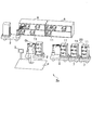
図1は、第1実施形態に係る物品搬送システムの概略構成を示す図である。
倉庫内に設置された物品搬送システムZには、物品を収納したトレイ(収納部)11が格納された固定棚6が複数設置されている。
(Schematic configuration of the system)
FIG. 1 is a diagram illustrating a schematic configuration of an article transport system according to the first embodiment.
In the article conveyance system Z installed in the warehouse, a plurality of fixed
トレイ搬送車(搬送装置)2は、複数の固定棚6の間を巡回し、トレイ11を取り出し、取り出したトレイ11を順にトレイ搬送車2上に積載して保持する。そして、トレイ搬送車2は、所定のトレイ11をすべて取り出して積載すると、作業ステーションPに移動する。なお、トレイ搬送車2の詳細な構成は後記する。
作業者Opは、作業ステーションPで待機しており、トレイ搬送車2が複数のトレイ11を積載して搬送してくると、コントローラ1から送信された指示に従って所定のトレイ11から、所定の数の物品を取り出すピッキング作業を実施する。作業者Opは、例えば、作業ステーションPに設置されているステーション端末3に表示される内容を参照してピッキング作業を行う。
The tray conveyance vehicle (conveyance device) 2 circulates between the plurality of fixed
The worker Op is waiting at the work station P, and when the
作業者Opは、指示されたピッキング作業がすべて終了するとコントローラ1に作業終了を通知する。例えば、作業者Opはステーション端末3に備えられている作業終了ボタン(不図示)を押下することで、コントローラ1に作業終了を通知する。また、作業者Opが作業終了を通知しなくとも、作業ステーションPに設置したセンサ等から作業終了タイミングを自動的に検知し、コントローラ12に通知してもよい。ここで、センサはバーコードリーダ(不図示)等であり、作業者Opは物品に貼付されているバーコードを、バーコードリーダにかざすことで、バーコードリーダは、どの物品がピッキングされたかを判定する。そして、ピッキング対象となっている物品のすべてがピッキングされると、バーコードリーダが作業終了をコントローラ1に通知してもよい。
The worker Op notifies the
トレイ搬送車2は、コントローラ1からのピッキング作業終了通知を受け、所定の固定棚6の位置にトレイ11をひとつずつ戻す。トレイ11を戻す位置は、取り出した位置に戻してもよいし、オーダの状況からトレイ11の使用頻度に応じて戻す位置を決定してもよい。また、トレイ搬送車2は、積載したトレイ11をそのまま所定の位置に降ろしてもよい。つまり、トレイ搬送車2は、固定棚6にトレイ11を戻さず、所定の位置に降ろしてもよい。
Upon receipt of the picking work end notification from the
(ハードウェア構成図)
図2は、第1実施形態に係る物品搬送システムのハードウェア構成例を示す図である。適宜、図1を参照する。
物品搬送システムZは、WMS(Warehouse Management System)4、コントローラ1、トレイ搬送車2及びステーション端末3を有する。
<WMS>
WMS4は、倉庫又は工場内での物品に関するデータと作業に関するデータとを管理する。物品に関するデータには、例えば、物品の識別情報、及び当該物品が格納されたトレイ11の識別情報、固定棚6の位置情報等が登録された物品格納データ等がある。また、作業に関するデータには、例えば、配送先と当該配送先に配送される物品の識別情報との関係等が登録されたオーダ等がある。WMS4は、図示しない入力装置を介して入力されたオーダを基にオーダデータ151を生成して、コントローラ1へ送信する。また、物品格納データをコントローラ1へ送信する。
(Hardware configuration diagram)
FIG. 2 is a diagram illustrating a hardware configuration example of the article transport system according to the first embodiment. Reference is made to FIG. 1 as appropriate.
The article transport system Z includes a WMS (Warehouse Management System) 4, a
<WMS>
The
<コントローラ>
コントローラ1は、WMS4から送信されたオーダを管理し、トレイ搬送車2にトレイ11の積載及び搬送の指示を行う。
コントローラ1は、一般的な計算機であり、メモリ101、送受信装置102、CPU(Central Processing Unit)103、入出力装置104及び記憶装置105を有する。メモリ101、入出力装置104、送受信装置102、CPU103及び記憶装置105は、バスを介して相互に接続されている。
CPU103は、各種演算処理を実行する。
記憶装置105は非揮発性の非一時的な記憶媒体であり、各種プログラム及び各種データが記憶される。
メモリ101は揮発性の一時的な記憶媒体である。メモリ101には、記憶装置105に記憶された各種プログラム及び各種データがロードされる。そして、CPU103がメモリ101にロードされた各種プログラムを実行し、メモリ101にロードされた各種データを読み書きする。その結果、メモリ101において、処理部110及び処理部110を構成するデータ受信処理部111、オーダ選択処理部112、トレイ検索部(収納部検索部)113、搬送車選択部(搬送装置選択部)114、経路生成部115、送信処理部116、指示処理部117が具現化している。
<Controller>
The
The
The
The
The
データ受信処理部111は、WMS4からオーダデータ151を受信し、受信したオーダデータ151を記憶装置105に格納する。また、データ受信処理部111は、WMS4から物品格納データを受信し、受信した物品格納格データを記憶装置105の棚データ152、トレイデータ153、物品データ154として格納する。また、データ受信処理部111は、トレイ搬送車2や、ステーション端末3から送信された情報も受信する。
The data
オーダ選択処理部112は、データ受信処理部111で受信したオーダデータ151のうち、作業に使用するオーダをひとつ又は複数選択する。オーダは、受信した順に選択されてもよいし、何らかの基準に基づいて選択されてもよい。
トレイ検索部113は、オーダ選択処理部112で選択したオーダに該当する物品が収納されているトレイ11の位置を、トレイデータ153、棚データ152を検索することで検索する。
The order
The
経路生成部115は、搬送するトレイ11を取り出し、作業ステーションPに向かうトレイ搬送車2の巡回経路(適宜、経路と称する)を生成する。経路は地図データ155に記憶されているトレイ搬送車2が移動する対象エリアの地図座標を用いて検索、管理する。なお、経路は、このような地図座標ではなく、ノード、リンクのID等を用いてもよい。経路は、トレイ搬送車2が、ピッキング対象となっている、すべてのトレイ11格納位置にアクセスし、かつ最短の経路を求める。このような最短の経路は、例えば巡回セールスマン問題を解く組み合わせ最適化法を用いて求めることができる。
送信処理部116は、経路生成部115で作成した搬送順に基づく経路や、搬送するトレイ11に関する情報を指示として作成し、トレイ搬送車2に送信する。
また、送信処理部116は、WMS4や、ステーション端末3へも情報を送信する。
指示処理部117は、トレイ搬送車2が作業ステーションPに到着したときに送信する到着通知をコントローラ1が受信すると、オーダの識別情報、トレイ11の識別情報等を含むピッキング指示データを生成する。ピッキング指示データは、送信処理部116によってステーション端末3へ送信される。
The
The
The
When the
記憶装置105には、オーダデータ151、棚データ(記憶部)152、トレイデータ153、物品データ154及び地図データ155等が格納されている。
オーダデータ151は、WMS4によって生成され、送信されたピッキングのオーダに関するデータであり、配送される物品の識別情報、配送される物品の個数、配送先に関する情報等が登録される。
棚データ152は、倉庫内における固定棚6の位置や、トレイ11が格納されている位置に関するデータ等が登録される。
トレイデータ153は、個々のトレイ11の構造や、そのトレイ11に格納されている物品に関するデータ等が登録される。
物品データ154は、個々の物品に関するデータ等が登録される。
地図データ155は、トレイ搬送車2が走行する領域(ここでは倉庫)の地図に関するデータである。
The
The
In the
In the
In the
The
なお、オーダデータ151、棚データ152、トレイデータ153及び物品データ154については後記する。
また、本実施形態では、WMS4から送信される物品格納データを基に、オーダデータ151、棚データ152、トレイデータ153及び物品データ154が生成されるとしているが、これらのデータが、予め、コントローラ1の記憶装置105に格納されていてもよい。
The
In the present embodiment, the
送受信装置102は、WMS4との間でデータを通信するインタフェースや、ステーション端末3との間でデータを通信するインタフェース等を有する。さらに、送受信装置102は、トレイ搬送車2との間でデータを通信するインタフェースも有する。なお、コントローラ1とWMS4及びステーション端末3とは、有線で接続されても無線で接続されてもよい。コントローラ1とトレイ搬送車2とは無線で接続されるものとする。
The transmission /
<トレイ搬送車>
トレイ搬送車2は、コントローラ1から受信した指示に従って移動し、所定のトレイ11を固定棚6から取り出し、トレイ11を積載して搬送する。トレイ搬送車2は、指示されたすべてのトレイ11を取り出し終わると、作業ステーションPに移動する。トレイ搬送車2は、作業ステーションPに到着すると、到着通知をコントローラ1に送信する。
<Tray carrier>
The
トレイ搬送車2は、メモリ201、送受信装置202、CPU203、及び記憶装置204を有する。メモリ201、送受信装置202、CPU203及び記憶装置204は、バスを介して相互に接続されている。
CPU203は、各種演算処理を実行する。
記憶装置204は非揮発性の非一時的な記憶媒体であり、各種データが記憶される。
メモリ201は揮発性の一時的な記憶媒体である。メモリ201では、CPU203によって各種プログラムが実行され、各種データが読み書きされる。その結果、メモリ201において、処理部210及び処理部210を構成する移動制御部211、到着通知部212、取出制御部213、回転制御部214が具現化している。
The
The
The
The
移動制御部211は、コントローラ1から送信された指示(経路)に従って、トレイ搬送車2を移動させる。
到着通知部212は、トレイ搬送車2が作業ステーションPに到着すると、トレイ搬送車2が作業ステーションPに到達した旨の情報である到着通知をコントローラ1へ送信する。
取出制御部213は、後記する取出装置22(図3)を制御する。
回転制御部214は、後記する回転部271(図14)を制御する。なお、トレイ搬送車2が回転部271を有さない場合、回転制御部214は省略されてもよい。
The
When the
The take-out
The
記憶装置204には、コントローラ1から送信された指示に含まれている経路データ241や、経路データ241と自己位置とをマッチングするための地図データ242を有している。
The
<ステーション端末>
ステーション端末3は、指示処理部117から受信したピッキング指示データに基づいて、該当トレイ11の位置から所定の数の物品を取り出す指示を表示装置304に表示する。作業者Opは表示装置304に表示されている指示に基づき物品のピッキング作業を実施する。ピッキング作業が終了すると、ステーション端末3はコントローラ1に作業終了通知を送信する。
<Station terminal>
Based on the picking instruction data received from the
ステーション端末3は、メモリ301、送受信装置302、CPU303、表示装置304及び読取装置305を有する。メモリ301、送受信装置302、CPU303、表示装置304及び読取装置305は、バスを介して相互に接続されている。
CPU303は、各種演算処理を実行する。
メモリ301は揮発性の一時的な記憶媒体である。メモリ301では、CPU303によって各種プログラムが実行され、各種データが読み書きされる。この結果、処理部310及び処理部310を構成する表示処理部311、作業監視部312、通知部313が具現化している。
The
The
The
表示処理部311は、コントローラ1から送信されたピッキング指示データに基づいて、ピッキング指示を表示装置304に表示させる。
作業監視部312は、読取装置305で読み取られた情報を基に、ピッキング作業の進捗度合いを監視する。
通知部313は、ピッキング作業が終了すると、作業終了通知をコントローラ1へ送信する。
The
The
When the picking work is completed, the
表示装置304は、作業者Opに対するピッキング指示を表示する。
読取装置305は、バーコードリーダや、RFIDリーダ等であり、物品に貼付されているバーコードや、RFIDタグの情報を読み取る。
The
The
<トレイ搬送車の詳細な構成>
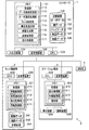
図3は、本実施形態に係るトレイ搬送車の外観例を示す図である。
トレイ搬送車2は、本体部21、取出装置22、格納部23を有している。本体部21の下部には、車輪が設置されており、前進、後進、方向転換等が可能である。
取出装置22は、固定棚6からトレイ11を取り出し、取り出したトレイ11を本体部21に設置されている格納部23に格納する。取出装置22の詳細は後記する。
<Detailed configuration of tray carrier>
FIG. 3 is a diagram illustrating an external appearance example of the tray transporter according to the present embodiment.
The
The take-out
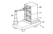
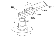
図4は、取出装置の具体的な構成例の一を示す図である。
図4に示すように、取出装置22は、上下伸縮部251、アーム部252及びキャッチャ部253を有している。
上下伸縮部251は、図4に示すように、トレイ搬送車2の本体部21に回転可能に設置されており、例えば、内部に備えられている多段油圧シリンダで伸縮する多段伸縮シリンダであり、垂直方向(図中Z方向)に伸縮可能である。なお、上下伸縮部251は、この構成に限らない。
アーム部252は、上下伸縮部251の上部に設置され、例えば、図4に示すような機構によって水平方向(図中X方向)に伸縮可能となっている。なお、アーム部252の伸縮機構は、図4に示すような機構に限らず、直動ガイドレール機構等が用いられてもよい。
アーム部252の先端には、フォーク式のキャッチャ部253が取り付けられている。
FIG. 4 is a diagram illustrating a specific configuration example of the take-out apparatus.
As illustrated in FIG. 4, the take-out
As shown in FIG. 4, the vertical extension /
The
A fork-
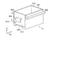
図5は、本実施形態に係るトレイの具体的な構成例の一を示す図である。
トレイ11には収納部601の左右の面にツメ602が設けられている。そして、このツメ602を前記したロボットハンドの先端にフォーク式のキャッチャ部253が引っ掛けることで、トレイ11を移動することを実現している。
また、トレイ11には前面、及び背面にフック603が設けられている(図5において、背面のフック603は隠れている)。さらに、さらに、トレイ11の底部には凹型のへこみ部604が設けられている。フック603及びへこみ部604の用途については後記する。
なお、トレイ11にはフック603、ツメ602、へこみ部604を全て備える必要はなく、それぞれの構成を1つ、又は複数備える構成を採用することも可能である。
なお、トレイ11には、上部に蓋がついていないことを想定しているが、蓋が付いていてもよい。
FIG. 5 is a diagram illustrating a specific configuration example of the tray according to the present embodiment.
The
In addition, the
Note that the
The
なお、トレイ11の面611は、矢印612の方向に開閉可能であり、作業者Opは面611を開けることで、トレイ11の中に入っている物品を取り出す。面611に対面する面613も同様に開閉可能である。ちなみに、図1等では図が煩雑になるのを避けるため、面611が開閉可能となる構造については図示省略してある。
Note that the
次に、図4と、図5とを参照して、図4に示す取出装置22によるトレイ11の運搬について説明する。
図4に示すように、アーム部252の先端にフォーク式のキャッチャ部253が取り付けられている。取出装置22は、上下伸縮部251による図中Y方向への回転、及び、上下伸縮部251及びアーム部252の伸縮により、キャッチャ部253をトレイ11の左右の面に設けられたツメ602(後記)の下部に差し入れる。その後、取出装置22は、上下伸縮部251を伸長させることで、トレイ11を持ち上げ、その後、アーム部252が縮退することで、トレイ11が固定棚6から引き出される。引き出したトレイ11をトレイ搬送車2の格納部23に格納する際には、トレイ11が引き出されるときの動作と反対の動作が行われる。
Next, with reference to FIG. 4 and FIG. 5, conveyance of the
As shown in FIG. 4, a fork-
<データ構成>
(オーダデータ)
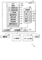
図6は、本実施形態に係るオーダデータの例を示す図である。
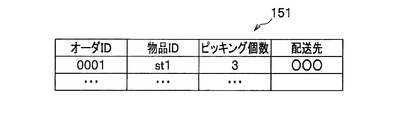
オーダデータ151は、オーダID、物品ID、ピッキング個数及び配送先等の各欄を有している。
オーダIDは、オーダが生成されたときにWMS4によって付与されるオーダの識別情報である。
物品IDは、物品毎に付与されている識別情報である。
ピッキング個数は、ピッキングされる個数である。
配送先は、ピッキングされた物品の配送先である。
<Data structure>
(Order data)
FIG. 6 is a diagram illustrating an example of order data according to the present embodiment.
The
The order ID is order identification information given by the
The article ID is identification information assigned to each article.
The number of picking is the number to be picked.
The delivery destination is a delivery destination of the picked article.
(棚データ)
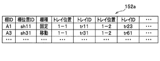
図7は、本実施形態に係る棚データの例を示す図である。
棚データ152は、棚ID、棚位置ID、トレイ位置及びトレイIDの各欄を有している。トレイ位置、トレイIDは、対の情報となっており、この対の情報が棚IDに対して複数格納されている。
棚IDは、固定棚6毎に付与されている識別情報である。
棚位置IDは、倉庫内における固定棚6の位置を示す識別情報である。棚位置IDは、図示しない棚位置データ等で座標と一対一に対応付けられているため、棚位置IDが定められると、倉庫内における固定棚6の位置も定まる。なお、棚位置IDと対応付けられる座標とは、固定棚6の中央部の座標が考えられるが、この他の部分の座標が用いられてもよい。
(Shelf data)
FIG. 7 is a diagram illustrating an example of shelf data according to the present embodiment.
The
The shelf ID is identification information given to each fixed
The shelf position ID is identification information indicating the position of the fixed
トレイ位置はトレイ11が格納されている固定棚6における間口の位置を示し、トレイIDはトレイ11毎に付与されている識別情報である。例えば、トレイID「tr11」を有するトレイ11のトレイ位置は、棚ID「A1」を有する固定棚6の下から1段目、向かって左から1つ目の間口に格納されている(トレイ位置「1−1」)。同様に、トレイID「tr23」を有するトレイ11のトレイ位置は、棚ID「A1」を有する固定棚6の下から1段目、向かって左から2つ目の間口に格納されている(トレイ位置「1−2」)。
The tray position indicates the position of the frontage in the fixed
(トレイデータ)
図8は、本実施形態に係るトレイデータの例を示す図である。
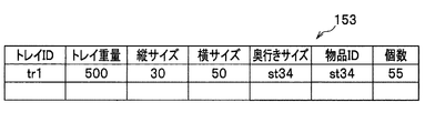
トレイデータ153は、トレイID、トレイ重量、縦サイズ、横サイズ、奥行きサイズ、物品ID及び個数の各欄を有している。
トレイIDは、トレイ11毎に付与されている識別情報である。
トレイ重量は、トレイ11の重量(中に格納されている物品の重量を含まない)である。
縦サイズは、トレイ11の縦方向(図5のZ軸方向)の長さである。
横サイズは、トレイ11の横方向(図5のX軸方向)の長さである。
奥行きサイズは、トレイ11の奥行き方向(図5のY軸方向)の長さである。
物品IDは、該当するトレイ11に格納されている物品を示す識別情報である。
個数は、該当するトレイ11に格納されている物品の個数である。
例えば、トレイID「tr1」を有するトレイ11には、物品ID「st34」で示される物品が55個格納されている。
(Tray data)
FIG. 8 is a diagram illustrating an example of tray data according to the present embodiment.
The
The tray ID is identification information assigned to each
The tray weight is the weight of the tray 11 (not including the weight of the articles stored therein).
The vertical size is the length of the
The horizontal size is the length of the
The depth size is the length of the
The article ID is identification information indicating an article stored in the corresponding
The number is the number of articles stored in the corresponding
For example, the
(物品データ)
図9は、本実施形態に係る物品データの例を示す図である。
物品データ154は、物品に付与される識別情報である物品IDと、その物品の重量との各欄を有している。
なお、第1実施形態では、トレイデータ153のトレイ重量、縦サイズ、横サイズ、奥行きサイズの各欄及び物品データ154が省略されてもよい。
(Article data)
FIG. 9 is a diagram illustrating an example of article data according to the present embodiment.
The
In the first embodiment, the tray weight, vertical size, horizontal size, and depth size columns of the
(フローチャート)
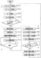
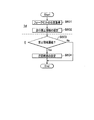
図10は、第1実施形態に係るピッキングシステムにおける処理の手順を示すフローチャートである。適宜、図1〜図9を参照する。
まず、WMS4がオーダデータ151を送信し(S101)、コントローラ1のデータ受信処理部111がオーダデータ151を受信する(S102)。データ受信処理部111は、受信したオーダデータ151を記憶装置105に格納する。物品格納データは、予めWMS4から送信され、棚データ152、トレイデータ153、物品データ154として格納される。
次に、オーダ選択処理部112が、オーダデータ151の中から1つのオーダを選択する(S103)。具体的には、オーダ選択処理部112は記憶装置105のオーダデータ151から未処理のオーダレコードを1つ又は複数取得する。前記したように、オーダは、受信した順に選択されてもよいし、何らかの基準に基づいて選択されてもよい。なお、選択されるオーダの数は、格納部23の棚数等である。
次に、トレイ検索部113が、トレイデータ153、棚データ152を検索して、ピッキング対象のトレイ11の位置(トレイ位置)を検索する(S104)。
(flowchart)
FIG. 10 is a flowchart illustrating a processing procedure in the picking system according to the first embodiment. Reference is made to FIGS.
First, the
Next, the order
Next, the
トレイ位置の抽出は以下の手順で行われる。
(A1)まず、トレイ検索部113は、ステップS103で選択したオーダ(オーダレコード)からピッキング対象の物品IDを取得する。
(A2)次に、トレイ検索部113は、(A1)で取得した物品IDをキーとして、トレイデータ153を検索して、ピッキング対象となっている物品を収納しているトレイ11のトレイIDを取得する。
(A3)そして、トレイ検索部113は、(A2)で取得したトレイIDをキーとして、棚データ152を検索し、棚位置IDと、トレイ位置を取得する。
このとき、ひとつの種類の物品が複数のトレイ11に別れて格納されている場合、対象トレイ検索部113は、該当する物品が格納されているすべてのトレイ11の位置及びトレイ11の識別情報を検索する。
Extraction of the tray position is performed according to the following procedure.
(A1) First, the
(A2) Next, the
(A3) Then, the
At this time, when one type of article is stored separately in the plurality of
次に、オーダ選択処理部112は、すべてのオーダについて、トレイ位置の検索を完了したか否かを判定する(S105)。
ステップS105の結果、すべてのオーダについて、トレイ位置の検索を完了していない場合(S105→No)、オーダ選択処理部112はステップS103へ処理を戻す。
Next, the order
As a result of step S105, when the tray position search has not been completed for all orders (S105 → No), the order
ステップS105の結果、すべてのオーダについて、トレイ位置の検索を完了している場合(S105→Yes)、搬送車選択部114は、取得した棚位置IDを基に、トレイ搬送車2を選択する(S111)。このとき選択されるトレイ搬送車2は、取得されたトレイ位置に最も近いところを走行し、かつ、固定棚6を搬送中ではないトレイ搬送車2である。なお、コントローラ1は、トレイ搬送車2の位置を常に把握している。
As a result of step S105, when the tray position search has been completed for all orders (S105 → Yes), the transport
次に、経路生成部115は、ステップS111で選択したトレイ搬送車2の位置、棚位置ID及びトレイ位置を基に、経路を生成する(S112)。このとき、経路生成部115は、ピッキング対象となるトレイ11をすべて巡回し、かつ、経路距離が最短となるよう経路を生成する。
そして、送信処理部116は、ステップS111で選択したトレイ搬送車2に経路データ241を送信すると共に、オーダID、棚位置、トレイ位置を組とした搬送車制御情報を送信する(S113)。なお、棚位置は、前記したように棚位置IDをキーとして、図示しない棚位置データを検索することで取得される。
経路データ241、搬送車制御情報を受信したトレイ搬送車2の移動制御部211は、経路データ241に従って走行しながら、搬送車制御情報に含まれる棚位置、トレイ位置にてトレイ11を積載しつつ、作業ステーションPへ移動する(S114)。
Next, the
Then, the
The
トレイ搬送車2の移動制御部211は、自身が作業ステーションPに到着したか否かを判定する(S115)。ステップS115の処理は公知の技術であるため、ここでは詳細な説明を省略する。
ステップS115の結果、作業ステーションPに到着していない場合(S115→No)、移動制御部211はステップS114に処理を戻し、トレイ搬送車2は移動を続ける。
The
If the result of step S115 is that the work station P has not been reached (S115 → No), the
ステップS115の結果、作業ステーションPに到着した場合(S115→Yes)、到着通知部212がコントローラ1へ到着通知を送信する(S121)。到着通知には、オーダID等が含まれている。
到着通知を受信したコントローラ1の指示処理部117は、到着通知に含まれているオーダIDをキーとして、オーダデータ151、トレイデータ153を検索し、オーダID、トレイID、物品ID、ピッキング個数等が組となったピッキング指示データを生成する(S122)。
そして、送信処理部116は、生成したピッキング指示データをステーション端末3へ送信する(S123)。
As a result of step S115, when arrival at the work station P (S115 → Yes), the
The
Then, the
ピッキング指示データを受信したステーション端末3の表示処理部311は、表示装置304にトレイID、物品ID、ピッキング個数といったピッキング情報を表示する(S124)。ステップS124は、表示処理部311は、格納部23におけるピッキング対象のトレイ11の位置を表示装置304に表示させてもよい。このような情報は、以下のようにして管理できる。すなわち、トレイ搬送車2の格納部23における各間口に識別情報を予め付しておく。コントローラ1の処理部110は、トレイ搬送車2の格納部23において、どの間口に、どのトレイ11を格納するかを決めておく。すなわち、処理部110は、トレイIDと、格納部23の間口の識別情報をひも付けて記憶しておく。この情報が、ステーション端末3へ送られることで、ステーション端末3の表示処理部311が、格納部23におけるピッキング対象のトレイ11の位置を表示装置304に表示させることができる。
作業者Opは、表示装置304の表示に従ってピッキングを行う。
Upon receiving the picking instruction data, the
The worker Op performs picking according to the display on the
ステーション端末3の作業監視部312は、すべてのピッキングが終了したか否かを判定する(S125)。
例えば、作業監視部312は、以下の手順にて作業を監視する。ステーション端末3には、図2で示すように、バーコードリーダや、RFIDリーダ等の読取装置305が設置されている。作業者Opは、ピッキング対象の物品をピッキングする毎に、物品に貼付されているバーコードや、RFIDタグを読取装置305にあてる。作業監視部312は、送信された物品に関する情報を基に、どの物品がどの数だけピッキングされたかを管理する。
The
For example, the
ステップS125の結果、すべてのピッキングが終了していない場合(S125→No)、作業監視部312はステップS125へ処理を戻す。
ステップS125の結果、すべてのピッキングが終了している場合(S125→Yes)、ステーション端末3の通知部313が作業終了通知をコントローラ1へ送信する(S131)。作業終了通知には、作業が終了したオーダのオーダID等が含まれている。
As a result of step S125, when all picking has not been completed (S125 → No), the
As a result of step S125, when all picking has been completed (S125 → Yes), the
作業終了通知を受信したコントローラ1の送信処理部116は、作業終了通知をWMS4へ送信する(S132)。作業終了通知を受信したWMS4はステップS101へ処理を戻り、新たなオーダデータ151をWMS4から受信する。
Upon receiving the work end notification, the
なお、ステップS112及びステップS113の処理は、所定時間毎に行われてもよい。また、オーダ選択処理部112は、ステップS103において、トレイデータ153及び物品データ154を参照して、搬送するトレイ11の重量が所定の重量を超えないよう、オーダを選択してもよい。
Note that the processing of step S112 and step S113 may be performed every predetermined time. Further, in step S103, the order
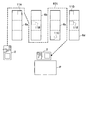
図11は、図10の処理によって生成された経路の例を示す図である。
トレイ搬送車2は、固定棚6aに格納されているトレイ11A、固定棚6bに格納されているトレイ11B、固定棚6cに格納されているトレイ11C、格納6dに格納されているトレイ11D及びトレイ11Eを順に取り出す。その後、取出したトレイ11A〜11Eを積載して作業ステーションPに搬送する。ここで、コントローラ1は、待機しているトレイ搬送車2から最も近いトレイ11Aを最初の取出対象とし、次にトレイ11Aからから最も近い(距離が最も短くなる)トレイ11Bを次の巡回先とする。そして、コントローラ1は、同様に、トレイ11Bから距離の近いトレイ11Cを取出対象とし、以下、同様にトレイ11C→トレイ11D→トレイ11Eの順にトレイ搬送車2が巡回するよう経路601を生成する。
FIG. 11 is a diagram illustrating an example of a route generated by the process of FIG.
The
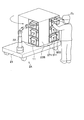
(トレイ搬送車における各機構の変形例)
図12は、第1実施形態における取出装置の他の変形例を示す図である。
図12における取出装置22bは、上下伸縮部251、テレスコピックアーム252bを有している。
上下伸縮部251は、図4に示す機構と同様であるので、ここでの説明を省略する。
テレスコピックアーム252bは各アーム281A,281B,281Cを有している。このうち、アーム281A,281Bの上部には、例えば、ピニオンギアが設けられており、このピニオンギアと噛み合うラックギア(不図示)がアーム281B,281Cの下部に備えられている。そして、ピニオンギアが回転することにより、テレスコピックアーム252bが図中X方向に直線的に伸縮する。ここでは、テレスコピックアーム252bが3段のアーム281A,281B,281Cを有する構造であるが、3段に限らない。
(Modification of each mechanism in the tray transporter)
FIG. 12 is a view showing another modification of the take-out device in the first embodiment.
The take-out
The vertical
The
次に、図5と図12とを参照して、図12における取出装置22bによるトレイ11の運搬について説明する。
図5に示すように、トレイ11には前面、及び背面にフック603が設けられている(図5において、背面のフック603は隠れている)。
図5に示すトレイ11の下部に設けられているへこみ部604に、図12に示すテレスコピックアーム252bが上下、前後に移動されることで差し入れられる。その後、上下伸縮部251が伸長されることで、トレイ11が持ち上げられ、その後、テレスコピックアーム252bが縮退することで、トレイ11が固定棚6から引き出される。引き出したトレイ11をトレイ搬送車2の格納部23に格納する際には、トレイ11が引き出されるときの動作と反対の動作が行われる。
Next, transportation of the
As shown in FIG. 5, hooks 603 are provided on the front surface and the back surface of the tray 11 (in FIG. 5, the
The
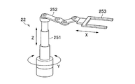
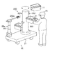
図13は、第1実施形態における格納部の他の変形例の一を示す図である。
図13に示す格納部23Aは、固定棚6の幅に設けられた2つの枠に複数のツメ部261が枠の内側に向けて設けられている。このツメ部261で、図5に示すトレイ11のツメ602が支えられることで、格納部23Aはトレイ11を格納する。
FIG. 13 is a diagram illustrating another modification of the storage unit in the first embodiment.
In the
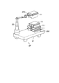
図14は、第1実施形態に係るトレイ搬送車の構成例の一を示す図である。
図14において、図3と同様の構成については、同一の符号を付して説明を省略する。
図14に示すトレイ搬送車2Aは、図3の格納部23Bの下部に回転部271が設けられている。トレイ搬送車2Aが、作業ステーションP(図1)に到着すると、この回転部271が回転することにより、格納部23Bの取出し口が作業者Opの方向に向けられる。トレイ搬送車2Aの処理部210が、自身がどちらに向いているかを検知することは容易であるので、回転制御部214がどの程度、回転部271を回転させるかを算出することは容易である。
なお、トレイ11のフック603は、図14に示すように面611を開閉させる際の取っ手にもなる。
FIG. 14 is a diagram illustrating an example of a configuration of the tray transporter according to the first embodiment.
14, the same components as those in FIG. 3 are denoted by the same reference numerals and description thereof is omitted.
A
The
図14に示す構成とすることで、トレイ搬送車2Aが作業ステーションPに到着すると、トレイ11の取出し口を作業者Opのいる方向に向けることが可能となるので、ピッキング作業の効率を向上させることができる。
With the configuration shown in FIG. 14, when the
また、図14に示すトレイ搬送車2Aでは、格納部23Bが直方体の形を有しており、その側面それぞれにトレイ11の取出口が備えられている。取出装置22が格納部23Bにトレイ11を格納する際には、回転部271が格納部23Bを回転させることで、それぞれの側面に設けられている取出口へトレイ11を順に格納する。また、作業者Opがトレイ11を取り出す際には、回転部271が格納部23Bを回転させることで、それぞれの側面に設けられている取出口からトレイ11が順に取り出される。
このようにすることで、トレイ搬送車2Aが、図1に示すトレイ搬送車2より多くのトレイ11を搬送することができる。
なお、図14では、格納部23Bの形状を直方体の形を有しており、その側面それぞれにトレイ11の取出口が備えられている形としたが、これに限らず、図3に示すような格納部23を有してもよい。
Further, in the
By doing in this way, the
In FIG. 14, the shape of the
前記したように、格納部23Bの各間口に予め識別情報を付しておくことで、どのトレイ11が、どの間口に格納されているかが管理される。この情報が、トレイ搬送車2へ送信されることで、トレイ搬送車2の回転制御部214(図2)は、回転部271をどの程度回転させるかを決定することができる。
As described above, by attaching identification information to each frontage of the
図15は、第1実施形態に係るトレイ搬送車の別の構成例の一を示す図である。
図15に示すトレイ搬送車2Bの格納部23Cは、例えば、ポール267に対して、2段のテレスコピックアーム264が上下方向(Z軸方向)に複数備えられている。縮退状態にある各テレスコピックアーム264上に固定棚6から取り出されたトレイ11が載置される。トレイ11がテレスコピックアーム264上に載置された状態で、トレイ搬送車2Bは、作業ステーションPに向かう。トレイ搬送車2Bが作業ステーションPに到達すると、作業者Opのいる方向へテレスコピックアーム264が伸長することで、トレイ11が作業者Opに差し出される。
なお、トレイ11が載置される箇所は、図15のようなテレスコピックアーム264ではなく、単なる板状のものとしてもよい。
FIG. 15 is a diagram showing one example of another configuration example of the tray transporter according to the first embodiment.
The
It should be noted that the place where the
図15に示す構成とすることで、トレイ搬送車2Bが作業ステーションPに到着すると、トレイ11が作業者Opに差し出されるので、ピッキング作業の効率を向上させることができる。
ポール267は回転可能に備えられており、トレイ搬送車2Dが作業ステーションPに到着すると、ポール267が回転し、テレスコピックアーム264上のトレイ11の取り出し口が作業者Opの方向に向くようにする。図15では、ポール267が回転して、トレイ11の取り出し口が作業者Opの方向に向いている状態を示している。
With the configuration shown in FIG. 15, when the
The
図16は、第1実施形態に係るトレイ搬送車の別の構成例を示す図である。
図16に示すトレイ搬送車2Cにおける取出装置22aは、上下伸縮部251、アーム部252a及びキャッチャ部253aを有している。
上下伸縮部251は、図4に示す機構と同様であるので、ここでの説明を省略する。
アーム部252aは棒状の形状を有しており、上下伸縮部251の上部内部に設置されているステッピングモータ等でアーム部252aが図中X軸方向に直線的に伸縮する。なお、アーム部252aは図16に示す構造に限らず、図4に示すような機構等でもよい。
アーム部252aの先端に取り付けられているキャッチャ部253aはフックとなっている。
また、格納部23Dは、ポール263に複数のフック262が設けられている構成を有している。
FIG. 16 is a diagram illustrating another configuration example of the tray transporter according to the first embodiment.
The take-out
The vertical
The
A
The
ここで、図5と図16とを参照して、図16に示す取出装置22aの動作について説明する。
図16に示す、キャッチャ部253aのフックが、図5に示すトレイ11のフック603にひっかけられた後、上下伸縮部251が伸長することで、トレイ11が持ち上げられる。その後、アーム部252aが縮退することで、トレイ11が固定棚6から引き出される。引き出したトレイ11をトレイ搬送車2Cの格納部23Dに格納する際には、トレイ11が引き出されるときの動作と反対の動作が行われる。
また、ポール263は回転可能に備えられており、トレイ搬送車2Cが作業ステーションPに到着すると、ポール263が回転し、ピッキング対象のトレイ11が作業者Opの方向に向くようにする。
Here, with reference to FIG. 5 and FIG. 16, operation | movement of the
The hook of the
The
格納部23Dの各フック262に予め識別情報を付しておくことで、どのトレイ11が、どの間口に格納されているかが管理される。この情報が、トレイ搬送車2へ送信されることで、トレイ搬送車2の回転制御部214(図2)は、ポール263をどの程度回転させるかを決定することができる。
By attaching identification information to each
図16に示す構成とすることで、トレイ搬送車2Cが作業ステーションPに到着すると、ピッキング対象のトレイ11が作業者Opのいる方向に向けられるので、ピッキング作業の効率を向上させることができる。
また、図16に示すように、ポール263の周方向にいろいろな方向にフック262が設けられている。このようにすることで、作業ステーションPにトレイ搬送車2Cが移動した際に、このポール263を回転させることで作業者Opがトレイ11中の商品をピッキングすることを容易にしている。
With the configuration shown in FIG. 16, when the
Further, as shown in FIG. 16, hooks 262 are provided in various directions in the circumferential direction of the
第1実施形態によれば、トレイ搬送車2はコントローラ1の指示に従って固定棚6から複数のトレイ11を取り出し、そのトレイ11をまとめて作業ステーションPに搬送する。これにより、作業ステーションPにおいて作業者Opは一度の搬送で搬送されてきたトレイ11から、該当物品を多数取り出すことができ、作業者Opのピッキング効率を向上させることができる。
According to the first embodiment, the
第1実施形態に係る物品搬送システムZによれば、ピッキング作業に必要なトレイ11だけを搬送することができることから、特許文献2に記載の技術のように無駄なトレイ11を運ぶことがなくなる。このため、全体的なトレイ搬送車2の移動距離を減らすことができ、トレイ搬送車2の稼働効率を向上させることができる。また、トレイ搬送車2の数を減らすことができ、コストを削減することも可能となる。
According to the article conveyance system Z according to the first embodiment, since only the
また、特許文献1の技術では、初期に設計した棚の位置や、棚の段数を変更する等といったレイアウトの変更が困難である。これに対して、第1実施形態に係る物品搬送システムZによれば、棚データ152、トレイデータ153、物品データ154のデータを変更するだけで、初期に設計した固定棚6の位置や、固定棚6の段数を変更する等といったレイアウトの変更を容易に行うことができる。
Also, with the technique of
さらに、第1実施形態に係る物品搬送システムZによれば、ピッキングに必要なトレイ11のみを搬送することができるため、特許文献2に記載の技術のように棚毎搬送するシステムよりも、1回の搬送で可能なピッキング量を増加させることができる。このため、第1実施形態に係る物品搬送システムZは、作業効率を向上させることができる。
Furthermore, according to the article transport system Z according to the first embodiment, only the
[第2実施形態]
(トレイ搬送車)
図17は、第2実施形態に係るトレイ搬送車の構成例を示す図である。なお、図17において、図3と同様の構成については同一の符号を付して説明を省略する。
第2実施形態では、トレイ11に蓋がついており、トレイ11を積重させることができる場合について記載する。
トレイ搬送車2Fは、図3における格納部23を有しておらず、代わりに、トレイ11を積重させる積重部291を有している。
なお、トレイ搬送車2Fの取出装置22におけるキャッチャ部253は、トレイ11の幅に応じて、フォークの幅を変えることができるが、ここでは、その機構についての図示及び具体的な説明を省略する。
[Second Embodiment]
(Tray carrier)
FIG. 17 is a diagram illustrating a configuration example of a tray transporter according to the second embodiment. In FIG. 17, the same components as those in FIG.
In the second embodiment, the case where the
The
The
第2実施形態における物品搬送システムZのハードウェア構成は、経路生成部115が以下の処理を行うこと以外は図2に示すハードウェア構成図と同様である。
第2実施形態において経路生成部115は、トレイ検索部113で検索した複数のトレイ11を積重した場合、トレイ搬送車2に搭載可能な高さ以下であるか判定を行う。また、経路生成部115トレイ11同士の積重が可能な順を判定する。例えば、小さなトレイ11の上部には大きなトレイ11を積重することができない、等のあらかじめ定めたルールに基づく。経路生成部115は、トレイ11の積重順を判定するが、複数の積重パターンがあれば、すべて列挙する。そして、経路生成部115は、列挙された積重パターンから適当なひとつのパターンを選択する。なお、トレイ11のサイズが同じものが複数含まれていれば、同じサイズのどのトレイ11を上又は下にしてもよいので、すべての重ね順を列挙する。このように、第2実施形態において、経路生成部115は、トレイ11の取り出し順も計算して積重していくよう、経路を生成する。
以下、図18を参照して、経路生成部115の具体的な処理を説明する。
The hardware configuration of the article transport system Z in the second embodiment is the same as the hardware configuration diagram shown in FIG. 2 except that the
In the second embodiment, when the plurality of
Hereinafter, specific processing of the
(フローチャート)
図18は、第2実施形態に係るピッキングシステムの経路生成に係る処理の手順を示すフローチャートである。なお、図18は、図10のステップS112の処理を詳細に説明するものである。適宜、図2、図7〜図9を参照する。
まず、経路生成部115は、ピッキング対象となっているトレイ11に優先順位を付加する(S201)。このとき、経路生成部115は、サイズの大きなトレイ11の優先順位を高くし、小さなトレイ11の優先順位を低くする。あるいは、経路生成部115は、重いトレイ11の優先順位を高くし、サイズの小さなトレイ11の優先順位を低くする。トレイ11のサイズと、トレイ11の重量とのどちらの優先順位を高くするかは、管理者等が設定可能であるが、ここでは、トレイ11のサイズの優先順位を重量より高くすることとする。また、経路生成部115は、トレイ11のサイズの優先順位と、重量の優先順位とを乗算した値をトレイ11の優先順位としてもよい。
(flowchart)
FIG. 18 is a flowchart illustrating a procedure of processing related to route generation of the picking system according to the second embodiment. FIG. 18 explains in detail the processing in step S112 in FIG. Reference is made to FIGS. 2 and 7 to 9 as appropriate.
First, the
そして、経路生成部115は、優先順位を基に経路を生成する(S202)。ここで、経路生成部115は、各トレイ11が格納されている固定棚6(トレイ11の格納場所)を中継地点とする。そして、優先順位の高いトレイ11の格納場所から順に巡回する経路を作成する。
このとき、経路生成部115は、トレイデータ153を参照し、優先順位の高い順からトレイ11を選択するたびに、選択されたトレイ11の高さを累積加算する。そして、経路生成部115は、累積加算の結果が所定の閾値を超えると、現在選択されているトレイ11の前に選択されたトレイ11までを積重対象とする。このようにすることで、経路生成部115は、過積重を防止することができる。
Then, the
At this time, the
なお、同じ優先順位のトレイ11が存在する場合、経路生成部115は、以下のように、すべての経路を作成する。例えば、同じ優先順位のトレイ11「A」、「B」、「C」があり、トレイ11「A」〜「C」より優先順位の低いトレイ11「D」が存在する場合、以下の6通りの経路を作成する。
(1)A→B→C→D (2)A→C→B→D (3)B→C→A→D (4)B→A→C→D (5)C→A→B→D (6)C→B→A→D
Note that, when the
(1) A → B → C → D (2) A → C → B → D (3) B → C → A → D (4) B → A → C → D (5) C → A → B → D (6) C → B → A → D
その後、経路生成部115は、経路を決定する(S203)。ここで、経路生成部115は、前記(1)〜(6)のように複数の経路が生成された場合、最も作業ステーションPまでの距離が短い経路を選択することで、経路を決定する。ここで、サイズ順でトレイ11を積重することを想定しているが、重量順でトレイ11を積重する場合でも同様の処理で経路を生成することができる。
Thereafter, the
図19は、第2実施形態に係る経路生成処理で生成された巡回経路を示す図である。
固定棚6aには一番サイズの大きいトレイ11Fが格納されている。また、固定棚6bには最も小さいサイズのトレイ11Jが格納されている。固定棚6cには、トレイ11Fの次にサイズの大きいトレイ11Gが格納されている。そして、固定棚6dには、最も小さいサイズのトレイ11Iと、トレイ11Iの次にサイズの小さいトレイ11Hが格納されている。つまり、各トレイ11の大きさは、トレイ11F>トレイ11G>トレイ11H>トレイ11I=トレイ11Jの順となっている。
FIG. 19 is a diagram illustrating a cyclic route generated by the route generation process according to the second embodiment.
The
経路生成部115は、トレイデータ153の縦サイズ、横サイズ及び奥行きサイズの欄を参照して、トレイ11F〜11Jのサイズを比較し、最もサイズの大きいトレイ11Fから取り出すよう経路を設定する。次に、経路生成部115は、トレイ11Fの次にサイズの大きいトレイ11Gを取り出すよう経路を設定する。そして、経路生成部115はトレイ11Gの次にサイズの大きいトレイ11Hを取り出すよう経路を設定する。トレイ11I及びトレイ11Jのサイズは、同じであるので、経路生成部115は、トレイ11I→トレイ11Jの経路及びトレイ11J→トレイ11Iの経路の両方を生成する。そして、経路生成部115は、作業ステーションPまでの経路の距離が最も短くなるトレイ11Iを先に取り出すトレイ11とする。つまり、経路生成部115は、トレイ11I→トレイ11Jの経路を選択する。
この結果、経路602が経路生成部115によって生成される。
The
As a result, the
なお、第2実施形態では、トレイ11の重量が、トレイデータ153に格納されているトレイ重量と、トレイデータ153と物品データ154から算出される物品の総重量とから求められるものとしているが、これに限らない。例えば、固定棚6の各間口に重量検知器が備えられ、これによってトレイ11の重量が測定されてもよい。
In the second embodiment, the weight of the
トレイ11を積重させる場合において、サイズの小さいトレイ11の上部にサイズの大きいトレイ11を設置することは、バランスの面から困難である。第2実施形態によれば、トレイ11のサイズによって、固定棚6から取り出す順番を決定し、さらに複数のトレイ11を積重することで、移動の効率化を行うことができる。
つまり、トレイ搬送車2Fが、図3に示すような格納部23にトレイ11を格納するのではなく、トレイを積重することにより、トレイ11を搬送する際には、搬送中にトレイ11がくずれないよう、トレイ11を積重する必要が生じる。本実施形態に係る物品搬送システムZによれば、トレイ11を大きい順もしくは重い順に積重するので、搬送中にトレイ11がくずれることを防止することができる。
When stacking the
That is, when the
[第3実施形態]
図20は、第3実施形態に係る物品搬送システムの概略構成を示す図である。
第3実施形態では、取出装置22を有していない搬送ユニット7を利用することで、作業効率を向上させることを目的とする。
図20において、図1と同様の構成については同一の符号を付して説明を省略する。
物品搬送システムZaにおいて、トレイ搬送車2は、ひとつ又は複数の搬送ユニット7を接続している。なお、トレイ搬送車2は搬送ユニット7を接続せず、単独で移動してもよい。搬送ユニット7は、取出装置22を有しておらず、上部にトレイ11が搭載可能な格納部23を有している。つまり、搬送ユニット7は、取出装置22を有していない以外はトレイ搬送車2と同様の構成を有している。搬送ユニット7は、図示しない連結器等によってトレイ搬送車2と物理的に連結可能である。トレイ搬送車2と、搬送ユニット7とが物理的に接続されている場合、動力はトレイ搬送車2が有するものとする。
トレイ搬送車2は、固定棚6からトレイ11を取り出すと、各搬送ユニット7の格納部23に積載する。積載方法は、第1実施形態と同様である。つまり、トレイ搬送車2は、取出装置22を用いて、トレイ11を搬送ユニット7、トレイ搬送車2に積載していく。
[Third Embodiment]
FIG. 20 is a diagram illustrating a schematic configuration of an article transport system according to the third embodiment.
The third embodiment aims to improve work efficiency by using the transport unit 7 that does not have the take-out
In FIG. 20, the same components as those in FIG.
In the article transport system Za, the
When the
このように、第3実施形態によれば、トレイ搬送車2と搬送ユニット7とが連携することにより、第1実施形態に示す物品搬送システムZより、一度に多くのトレイ11を搬送することが可能となる。
また、搬送ユニット7は、独立に駆動装置を有していてもよく、トレイ搬送車2に追随して移動するようにしてもよい。この場合、搬送ユニット7はトレイ搬送車2と物理的に連結していても、連結していなくてもよい。
As described above, according to the third embodiment, the
Moreover, the conveyance unit 7 may have a drive device independently, and you may make it move following the
第3実施形態によれば、第1実施形態の物品搬送システムZより作業の効率を向上させることができる。つまり、第1実施形態に示す物品搬送システムZより多くのトレイ11を一度に搬送することができるため、トータルの作業者Opの待ち時間を減らすことができ、第1実施形態の物品搬送システムZより作業の効率を向上させることができる。
また、搬送ユニット7には取出装置22を設置する必要がないため、すべてを取出装置22を備えたトレイ搬送車2とするよりコストを抑えることができる。
According to the third embodiment, work efficiency can be improved compared to the article transport system Z of the first embodiment. That is, since
Moreover, since it is not necessary to install the take-out
なお、トレイ11が蓋を有していることで、積重可能である場合、搬送ユニット7を第2実施形態のトレイ搬送車2Fから取出装置22を除いた構成としてもよい。この場合、コントローラ1は第2実施形態と同様の経路生成し、順にトレイ搬送車2F及び搬送ユニット7にトレイ11を積重していくことで、サイズ順に積重して搬送することが可能となる。
例えば、コントローラ1の経路生成部115は、まず、サイズが大きい等、優先順位の高いトレイ11を搬送ユニット7及びトレイ搬送車2Fに積重するよう経路を生成する。そして、サイズが中くらいのトレイ11を搬送ユニット7及びトレイ搬送車2Fに積重するよう経路を生成する。最後に、経路生成部115は、最もサイズの小さいトレイ11を搬送ユニット7及びトレイ搬送車2Fに積重するよう経路を生成する。また、経路生成部115は、トレイデータ153を参照して、搬送ユニット7及びトレイ搬送車2Fに積重されるトレイ11の高さが所定の高さ以下となるようにする。
In addition, when the
For example, the
[第4実施形態]
第4実施形態では、搬送車の選択及びトレイ搬送車2の渋滞が発生したときの対処について説明する。なお、第4実施形態における物品搬送システムZのハードウェア構成は図2に示すハードウェア構成と同様であるので、ここでの図示及び説明を省略する。
第4実施形態において、搬送車選択部114は、倉庫内に複数存在するトレイ搬送車2のうち、トレイ11の搬送に最適なトレイ搬送車2を決定する。
[Fourth Embodiment]
In the fourth embodiment, selection of a transport vehicle and a countermeasure when a traffic jam occurs in the
In 4th Embodiment, the conveyance
(フローチャート)
図21は、第4実施形態に係るコントローラの搬送車選択処理の手順を示すフローチャートである。なお、図21の処理は図10のステップS121のタイミングで行われる処理である。適宜、図2を参照する。
まず、搬送車選択部114は、倉庫内に存在する各トレイ搬送車2の位置を特定する(S301)。倉庫内に存在するトレイ搬送車2の位置特定は公知の技術であるので、ここでは詳細な説明を省略する。
次に、搬送車選択部114は、複数存在するトレイ搬送車2のうち、搬送作業を行っていないトレイ搬送車2を検索する(S302)。トレイ搬送車2が搬送作業を行っているか否かは、例えば、図示しないトレイ搬送車2のリストにおいて、搬送中のトレイ搬送車2にフラグを立てること等で容易に判定できる。
(flowchart)
FIG. 21 is a flowchart illustrating a procedure of the transport vehicle selection process of the controller according to the fourth embodiment. 21 is a process performed at the timing of step S121 in FIG. Reference is made to FIG. 2 as appropriate.
First, the transport
Next, the transport
そして、搬送車選択部114は、ステップS302で検索したトレイ搬送車2の中から、トレイ11を搬送するトレイ搬送車2を選択し(S303)、処理部110aは処理を図10のステップS122へリターンする。
ステップS303において、作業を行っていないトレイ搬送車2が複数存在する場合、搬送車選択部114は、ステップS301で特定した各トレイ搬送車2の位置を基に、搬送対象のトレイ11が格納されている位置に最も近いトレイ搬送車2を選択する。また、搬送車選択部114は、搬送作業を行っていないトレイ搬送車2のうち、巡回経路の総走行距離が最も短くなるトレイ搬送車2を選択してもよい。この場合、経路生成部115は、搬送作業を行っていないトレイ搬送車2のそれぞれについて巡回経路を生成する。
And the conveyance
In step S303, when there are a plurality of
さらに、すべてのトレイ搬送車2が作業中であった場合、搬送車選択部114は、以下の処理を行ってもよい。すなわち、搬送車選択部114は、処理対象となっているトレイ搬送車2における作業の終了時間と、他のトレイ搬送車2が搬送対象となっているトレイ11の位置まで向かう時間とを比較する。そして、搬送車選択部114は、処理対象となっているトレイ搬送車2の作業終了後に次の作業を割り当てた方が、他のトレイ搬送車2に作業を割り当てるよりも早いと判定した場合、作業中のトレイ搬送車2を選択してもよい。この場合、搬送車選択部114は、各トレイ搬送車2の位置や、速度、予め入力されている推定作業時間等から、トレイ搬送車2の作業終了時間を推定する。
Furthermore, when all the
第4実施形態によれば、トレイ搬送車2が複数存在する場合には、トレイ搬送車2の位置と作業状態から、適切なトレイ搬送車2に作業を割り振ることができる。
また、第4実施形態によれば、作業を行っていないトレイ搬送車2が複数存在する場合、搬送車選択部114は、対象のトレイ11が格納されている位置に最も近いトレイ搬送車2を選択することで、トレイ搬送車2がトレイ11の格納位置まで移動する距離を短くできる。これにより、物品搬送システムZbは、トレイ搬送車2の移動時間を短縮することができる。また、物品搬送システムZbは、トレイ搬送車2の搬送作業偏りを軽減することができる。
なお、搬送車選択部114によって作業対象となるトレイ搬送車2を決定すると、経路生成部115はトレイ搬送車2の現在の位置から各トレイ11の位置を鑑み、トレイ11を取り出すための搬送順序を作成する。この処理は、第1実施形態と同様の処理である。
According to the fourth embodiment, when there are a plurality of
Further, according to the fourth embodiment, when there are a plurality of
When the transport
[第5実施形態]
(ハードウェア構成図)
図22は、第5実施形態に係る物品搬送システムのハードウェア構成例を示す図である。
第5実施形態に示す物品搬送システムZbは、トレイ搬送車2が搬送中に他のトレイ搬送車2の影響を軽減しながら移動する。
特に、トレイ搬送車2の渋滞が発生したときの対処について説明する。
なお、図22において、図2と同様の構成については、同一の符号を付して説明を省略する。
図22において、図2と異なる点は、コントローラ1aの処理部110aが渋滞処理部(経路変更部)119を有している点である。
渋滞処理部119は、倉庫内において、トレイ搬送車2の渋滞が生じているか否かを判定し、渋滞が生じている場合、トレイ搬送車2に経路を変更するよう指示する。
なお、トレイ搬送車2及びステーション端末3については、図2と同様であるので、その詳細な構成については図示及び説明を省略する。
[Fifth Embodiment]
(Hardware configuration diagram)
FIG. 22 is a diagram illustrating a hardware configuration example of the article transport system according to the fifth embodiment.
The article transport system Zb shown in the fifth embodiment moves while reducing the influence of other
In particular, how to deal with the occurrence of a traffic jam in the
In FIG. 22, the same components as those in FIG. 2 are denoted by the same reference numerals and description thereof is omitted.
22 is different from FIG. 2 in that the
The traffic
Since the
(フローチャート)
図23は、第5実施形態に係るコントローラの渋滞時における処理の手順を示すフローチャートである。図23の処理は、適宜のタイミングで行われる処理である。適宜、図22を参照する。
まず、渋滞処理部119が、渋滞が生じているか否かを判定する(S401)。渋滞処理部119は、経路の予約が不可能であることをコントローラ1aから通知されたり、トレイ搬送車2の速度が閾値以下である状態が所定時間続いているトレイ搬送車2を検出されたりすると、渋滞が発生していると判定する。なお、トレイ搬送車2は、経路生成部115が作成した経路のうち、一定区間又は一定時間毎に経路を予約し、予約が完了すると該区間を進行するが、他のトレイ搬送車2によって予約する区間が占拠されていると、トレイ搬送車2は、経路の予約が不可能である旨をコントローラ1aへ通知する。
(flowchart)
FIG. 23 is a flowchart illustrating a processing procedure when the controller according to the fifth embodiment is congested. The process of FIG. 23 is a process performed at an appropriate timing. Reference is made to FIG. 22 as appropriate.
First, the traffic
ステップS401の結果、渋滞が生じていない場合(S401→No)、コントローラ1aの渋滞処理部119は処理を終了する。
ステップS401の結果、渋滞が生じている場合(S401→Yes)、渋滞処理部119は、渋滞で進むことができないトレイ搬送車2を特定する(S402)。
そして、渋滞処理部119は、特定したトレイ搬送車2に対して、積載中止を指示し(S403)、経路生成部115は、作業ステーションPへ向かうよう指示。具体的には、経路生成部115は、現在のトレイ搬送車2の位置から作業ステーションPへ向かう経路を生成し、送信処理部116がトレイ搬送車2へ生成した経路を送信する。このとき、渋滞処理部119は、例えば、トレイ搬送車2の位置と、最初に生成した経路から、トレイ搬送車2が現在どのトレイ11を取出しているかを特定し、さらに残っているトレイIDをWMS4へ送信する。WMS4では、送信されたトレイIDを基に、新たにオーダデータ151を生成する。
このようにすることで、作業予定であったが、他のトレイ搬送車2の影響によって作業が完遂できなかったトレイ11が存在しても、この作業については次の搬送に作業を繰り越すことができる。
If no traffic jam occurs as a result of step S401 (S401 → No), the traffic
As a result of step S401, when a traffic jam occurs (S401 → Yes), the traffic
Then, the traffic
By doing in this way, even if there is a
そして、トレイ搬送車2の移動制御部211は作業ステーションPへトレイ搬送車2を移動させる(S404)。
なお、図24の処理は省略されてもよい。
Then, the
Note that the process of FIG. 24 may be omitted.
このように、第5実施形態では、トレイ搬送車2の渋滞が生じていると判定され場合、トレイ11の取出作業を停止し、トレイ搬送車2を作業ステーションPへ向かわせる。
このようにすることで、トレイ搬送車2の渋滞が生じていても、とりあえず、積載しているトレイ11を作業ステーションPに搬送することができるので、時間短縮を図ることができる。
つまり、他のトレイ搬送車2による干渉があっても、状況に応じて搬送経路や搬送作業を変更することによって、効率のよい搬送を実施することができる。
As described above, in the fifth embodiment, when it is determined that there is a traffic jam in the
By doing in this way, even if there is a traffic jam in the
That is, even if there is interference from another
なお、トレイ搬送車2が複数台同じ領域で運行している場合、コントローラ1aは、他のトレイ搬送車2の位置と作業状況から、指示された経路を変更し、その時点において最短時間で移動できる経路へ変更してもよい。
When a plurality of
また、第5実施形態において、経路の予約が不可能であるか否かで渋滞の検出を行っているが、これに限らない。例えば、トレイ搬送車2同士で互いの位置を通知し合い、所定範囲に所定台数以上のトレイ搬送車2がある場合、トレイ搬送車2の処理部210が、渋滞が発生していると判定してもよい。あるいは、トレイ搬送車2の速度が所定速度以下になったら、渋滞処理部119は渋滞が発生していると判定してもよい。
また、コントローラ1aは経路決定時点で他のトレイ搬送車2の移動や作業状態を予測し、他のトレイ搬送車2の存在によって渋滞や待ちが発生する場合には、他のトレイ搬送車2を迂回するように経路を決定してもよい。
In the fifth embodiment, the congestion is detected based on whether or not the route reservation is possible, but the present invention is not limited to this. For example, when the
Further, the
[第6実施形態]
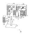
図24は、第6実施形態に係る物品搬送システムの概略構成を示す図である。図24において、図1と同様の構成については同一の符号を付して説明を省略する。
図24では、固定棚6と移動棚61とが混在する場合について説明する。
物品搬送システムZcにおいて、固定棚6に格納されているトレイ11は、トレイ搬送車2によって搬送される。搬送方法は、第1〜5実施形態の手法による。
移動棚61は、トレイ11又は物品を格納しており、棚搬送車(棚搬送装置)62によって搬送される。
移動棚61は、床下に棚搬送車62が入り込める程度の空間を有している。棚搬送車62は移動棚61の下に入り込み、移動棚61自体を持ち上げて搬送する。
棚搬送車62による移動棚61の搬送は、公知の技術であるため、棚搬送車62の詳細な処理については説明を省略する。
なお、移動棚61には、トレイ11又は物品が格納されている。
[Sixth Embodiment]
FIG. 24 is a diagram illustrating a schematic configuration of an article transport system according to the sixth embodiment. In FIG. 24, the same components as those in FIG.
In FIG. 24, the case where the fixed
In the article transport system Zc, the
The
The
Since the conveyance of the
The
移動棚61は、トレイ搬送車2によって、一度持ち上げられると複数種類の物品を搬送することが可能であるため、例えば、多頻度品が主に格納される。一方、固定棚6には、例えば、低頻度品を格納し、必要なトレイ11のみを搬送することが可能である。このように、第6実施形態によれば、利用頻度に応じて物品の格納先を変える等、柔軟な物品の格納が可能となる。なお、利用頻度ではなく、他の基準に基づいて格納先が選択されてもよい。
Since the
(ハードウェア構成図)
図25は、第6実施形態に係る物品搬送システムのハードウェア構成例を示す図である。
図25において、図2と同様の構成については、同一の符号を付して説明を省略する。
図25において、図2と異なる点は、物品搬送システムZcが、棚搬送車62を有している点である。さらに、図25において、図2と異なる点は、コントローラ1bの処理部110bが、搬送車種選択部(搬送装置種選択部)120を有している点である。さらに、図25において、図2と異なる点は、コントローラ1bの記憶装置105が、棚データ152aを有している点である。
搬送車種選択部120は、ピッキング対象となっている棚の種類に応じて、搬送車の種類(トレイ搬送車2、棚搬送車62)を選択する。
棚データ152aについては、後記する。
なお、トレイ搬送車2及びステーション端末3については、図2と同様であるので、その詳細な構成については図示及び説明を省略する。
また、棚搬送車62は、公知の技術であるため、その詳細な構成については図示及び説明を省略する。
(Hardware configuration diagram)
FIG. 25 is a diagram illustrating a hardware configuration example of the article transport system according to the sixth embodiment.
In FIG. 25, the same components as those in FIG.
25 is different from FIG. 2 in that the article transport system Zc has a
The transport vehicle type selection unit 120 selects the type of transport vehicle (
The
Since the
Moreover, since the
(棚データ)
図26は、第6実施形態に係る棚データの例を示す図である。
図26に示す棚データ152aが、図7に示す棚データ152と異なる点は、棚種の欄を有している点である。
棚種は、該当する棚の種類(固定棚6を示す「固定」、移動棚61を示す「移動」)が格納されている。
(Shelf data)
FIG. 26 is a diagram illustrating an example of shelf data according to the sixth embodiment.
The
The shelf type stores the type of the corresponding shelf (“fixed” indicating the fixed
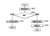
(フローチャート)
図27は、第6実施形態に係るピッキングシステムにおける処理の手順を示すフローチャートである。図27は、図10のステップS111で行われる処理である。適宜、図25及び図26を参照する。
まず、搬送車種選択部120は、棚データ152aを参照して棚種情報を取得する(S501)。
具体的には、図10のステップS104の段階で取得された棚IDをキーとして、棚データ152aの棚種の欄を参照することで、棚種情報を取得する。
(flowchart)
FIG. 27 is a flowchart illustrating a processing procedure in the picking system according to the sixth embodiment. FIG. 27 shows the processing performed in step S111 of FIG. Reference is made to FIGS. 25 and 26 as appropriate.
First, the transport vehicle type selection unit 120 acquires shelf type information with reference to the
Specifically, the shelf type information is acquired by referring to the column of the shelf type of the
次に、搬送車種選択部120は、棚種が固定棚6であるか、移動棚61であるかを判定する(S502)。
ステップS502の結果、棚種が固定棚6である場合(S502→固定棚)、搬送車種選択部120は、搬送車として、トレイ搬送車2を選択し(S503)、図10のステップS112の処理へリターンする。
また、ステップS502の結果、棚種が移動棚61である場合(S502→移動棚)、搬送車種選択部120は、棚搬送車62を選択し(S504)、経路生成部115は棚搬送車62へ送信するための経路を生成する(S505)。棚搬送車62の経路は公知の技術であるので、ここでの説明を省略する。
Next, the transport vehicle type selection unit 120 determines whether the shelf type is the fixed
As a result of step S502, when the shelf type is the fixed shelf 6 (S502 → fixed shelf), the transport vehicle type selection unit 120 selects the
If the result of step S502 is that the shelf type is the moving shelf 61 (S502 → moving shelf), the transport vehicle type selection unit 120 selects the shelf transport vehicle 62 (S504), and the
なお、第6実施形態において、トレイ搬送車2に関する処理は第1実施形態に示す処理と同様であり、棚搬送車62に関する処理は公知の技術であるので、具体的な説明は省略する。
第6実施形態によれば、物品の使用頻度等の状態に応じて棚(固定棚6と移動棚61)や、搬送車(トレイ搬送車2、棚搬送車62)を使い分けることにより、ピッキングステーションへの搬送効率を向上させることができ、ピッキング効率を向上させることができる。
In the sixth embodiment, the process related to the
According to the sixth embodiment, a picking station can be used by properly using shelves (fixed
[第7実施形態]
第7実施形態の説明の前に、第7実施形態に係る物品搬送システムZdの課題と目的を説明する。通常の固定棚6や、移動棚61では、作業者Opの手の届く高さの固定棚6や、移動棚61が用いられる。このため、固定棚6や、移動棚61の上方に無駄な空間ができてしまう。また、第6実施形態に示すような棚搬送車62による移動棚61を用いる場合も、棚搬送車62で持ち上げることができる移動棚61の重量や、高さに制限ができてしまうため、やはり、移動棚61の上方に無駄な空間ができてしまう。
第7実施形態では、ピッキング作業の効率を向上させつつ、棚の上方を有効に利用することができることを目的とする。
[Seventh Embodiment]
Prior to the description of the seventh embodiment, the problem and purpose of the article transport system Zd according to the seventh embodiment will be described. In the normal fixed
The seventh embodiment aims to effectively use the upper part of the shelf while improving the efficiency of the picking work.
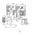
(システムの概略構成)
図28は、第7実施形態に係る物品搬送システムの概略構成を示す図である。なお、図28において、図1と同様の構成については同一の符号を付して説明を省略する。
物品搬送システムZdにおいて、固定棚6aは、下部に空間を有している。固定棚6aの棚段には物品が格納されたトレイ11が格納されたり、物品が直接格納されたりしている。物品搬送システムZdにおけるトレイ搬送車2は、第1〜第4実施形態と同様の構成を有するトレイ搬送車2の取出装置22によって、固定棚6aに格納されたトレイ11を取り出す。
移動棚61は、一定の高さを持つ棚である。移動棚61は、第6実施形態と同様、下方に棚搬送車62が侵入可能な空間を有している。第6実施形態と同様、棚搬送車62が移動棚61の下部空間に入り込み、移動棚61を持ち上げて搬送することで移動棚61が搬送される。
そして、移動棚61は固定棚6aの下部空間に設置される。
(Schematic configuration of the system)
FIG. 28 is a diagram illustrating a schematic configuration of an article transport system according to the seventh embodiment. In FIG. 28, the same components as those in FIG.
In the article transport system Zd, the fixed
The
The
このように、固定棚6aと移動棚61を上下方向に位置することにより、倉庫の上空間(移動棚61の上方の空間)を活用でき、倉庫内の保管効率を高めることができる。
また、トレイ搬送車2が上方に位置する固定棚6aの取り出し作業に時間を有する場合には、固定棚6aには低頻度品が格納される。これにより、時間がかかる上方の固定棚6aへのアクセス回数を減らすことができ、ピッキング作業全体の効率を上げることができる。
Thus, by positioning the fixed
In addition, when the
なお、第7実施形態において、トレイ搬送車2に関する処理は第1実施形態に示す処理と同様であり、棚搬送車62に関する処理は公知の技術であるので、具体的な説明は省略する。
In the seventh embodiment, the process related to the
[第8実施形態]
第8実施形態では、人が操作する機械と、トレイ搬送車2や、棚搬送車62等の自律装置が混在する場合について説明する。
(システムの概略構成)
図29は、第8実施形態に係る物品搬送システムの概略構成例を示す図である。なお、図29において、図1と同一の構成については、同一の符号を付して説明を省略する。
図29に示す物品搬送システムZeにおいて、固定棚6a及び移動棚61は第6実施形態と同様の構成を有している。
つまり、第6実施形態と同様、固定棚6aの下部空間に、移動棚61が設置されている。固定棚6aの物品は、トレイ搬送車2や、作業者Opが操作するフォークリフト(非自律移動装置)80によって取り出される。作業者Opは、監督者や、コントローラ1d(図30)の指示に従ってフォークリフト80を運転して物品を取り出したり、格納したりする。
[Eighth Embodiment]
In the eighth embodiment, a case will be described in which a machine operated by a person and autonomous devices such as the
(Schematic configuration of the system)
FIG. 29 is a diagram illustrating a schematic configuration example of an article transport system according to the eighth embodiment. 29, the same components as those in FIG. 1 are denoted by the same reference numerals, and the description thereof is omitted.
In the article transport system Ze shown in FIG. 29, the fixed
That is, like the sixth embodiment, the moving
第8実施形態では、人が操縦するフォークリフト80と、トレイ搬送車2や、棚搬送車62が衝突せずに移動するようにするため、フォークリフト80の位置がコントローラ1dに通知される。
フォークリフト80には、付属として取り付け可能な自己位置を取得・送信でき、着脱可能なアタッチメント装置(位置通知装置)8が取り付けられている。
In the eighth embodiment, the position of the
The
(ハードウェア構成図)
図30は、第8実施形態に係る物品搬送システムのハードウェア構成例である。
図30に示す物品搬送システムZeは、コントローラ1d、トレイ搬送車2、ステーション端末3に加えて、フォークリフト80(図29)に設置されるアタッチメント装置8を有している点で図2に示す物品搬送システムZと異なっている。
(Hardware configuration diagram)
FIG. 30 is a hardware configuration example of the article transport system according to the eighth embodiment.
The article conveyance system Ze shown in FIG. 30 has the
アタッチメント装置8は、メモリ801、送受信装置802、CPU803を有する。メモリ801、送受信装置802、CPU803は、バスを介して相互に接続されている。
CPU803は、各種演算処理を実行する。
メモリ801は揮発性の一時的な記憶媒体である。メモリ801では、CPU803によって各種プログラムが実行され、各種データが読み書きされる。その結果、メモリ801において、処理部810及び処理部810を構成する位置特定部811及び位置通知部812が具現化している。
The
The
The
位置特定部811は、倉庫内におけるアタッチメント装置8の位置を推定する。位置の推定は、アタッチメント装置8に内蔵されている図示しないカメラが床面等に貼付されたマーカを読み取ることによって自己位置を取得する。又は、アタッチメント装置8に内蔵されている図示しないレーザスキャナによる周辺の形状認識と地図との照合によって自己位置が推定されてもよい。あるいは、倉庫内に設置されたビーコン等の発信情報によって自己位置が推定されてもよい。なお、自己位置の推定手法は、これらの手法に限らない。
位置通知部812は、位置特定部811で推定されたアタッチメント装置8の位置(フォークリフト80の位置)をコントローラ1dへ通知する
The
The position notification unit 812 notifies the
また、コントローラ1dは、処理部110dが位置管理部(禁止領域設定部)121を有している点で、図2に示すコントローラ1と異なっている。
位置管理部121は、アタッチメント装置8から受信したフォークリフト80の位置(アタッチメント装置8の位置)を地図データ155に基づいて管理する。そして、位置管理部121は、フォークリフト80が位置する地図のリンク上にはトレイ搬送車2が走行しないように設定する。すなわち、位置管理部121は、フォークリフト80の周囲所定範囲をトレイ搬送車2の走行禁止領域とする。
The
The
(フローチャート)
図31は、第8実施形態に係る物品管理システムにおける処理の手順を示すフローチャートである。なお、図31の処理は、ピッキングシステムにおいて、所定の間隔で行われている処理である。適宜、図30を参照する。
位置管理部121が、フォークリフト80に取り付けられている位置通知部812から、フォークリフト80の位置を取得する(S601)。
次に、位置管理部121が、取得したフォークリフト80の位置を基に、トレイ搬送車2及び棚搬送車62の走行禁止領域を設定する(S602)。
そして、位置管理部121は、送信処理部116を介して走行禁止領域をトレイ搬送車2及び棚搬送車62に通知する。
(flowchart)
FIG. 31 is a flowchart illustrating a processing procedure in the article management system according to the eighth embodiment. Note that the processing in FIG. 31 is processing performed at a predetermined interval in the picking system. Reference is made to FIG. 30 as appropriate.
The
Next, the
Then, the
以下、トレイ搬送車2における処理について記載するが、棚搬送車62においても同様の処理が行われる。
トレイ搬送車2の移動制御部211は、これから予約しようとする経路が走行禁止領域を通過するか否かを判定する(S603)。
ステップS603の結果、これから予約しようとする経路が走行禁止領域を通過しない場合(S603→No)、トレイ搬送車2の移動制御部211は処理を終了する。
ステップS603の結果、これから予約しようとする経路が走行禁止領域を通過する場合(S603→Yes)、トレイ搬送車2の移動制御部211は迂回経路を設定する(S604)。
なお、本実施形態では、トレイ搬送車2が迂回経路を設定するものとしたが、これから予約しようとする経路が走行禁止領域を通過することを検知したトレイ搬送車2の移動制御部211が、コントローラ1dに走行禁止領域を通過する旨と、自己位置とを送信し、コントローラ1dの経路生成部115が迂回経路を生成してもよい。
Hereinafter, although the process in the
The
As a result of step S603, when the route to be reserved does not pass the travel prohibition area (S603 → No), the
As a result of step S603, when the route to be reserved passes through the travel prohibition area (S603 → Yes), the
In the present embodiment, the
図32は、第8実施形態に係る走行禁止領域の例を示す図である。
倉庫701の内部に棚702が設置されている。ここで、棚702は、固定棚6a及び移動棚61である。フォークリフト80が図32に示す位置に存在すると、この位置から所定範囲の周辺の領域が走行禁止領域711となる。
FIG. 32 is a diagram illustrating an example of a travel prohibited area according to the eighth embodiment.
A
第8実施形態によれば、フォークリフト80等、人が操作する装置と、トレイ搬送車2や、棚搬送車62のような自律移動する装置とが混在する場合、フォークリフト80の位置をトレイ搬送車2や、棚搬送車62に通知するために、新たなフォークリフト80を導入することなく、着脱可能なアタッチメント装置8の利用により、汎用的なフォークリフト80を使用することができる。これにより、利便性の向上を図ることができるとともに、コストを抑えることができる。
また、フォークリフト80の位置の周辺が走行禁止領域として設定されることで、フォークリフト80とトレイ搬送車2や、棚搬送車62の衝突を防ぐように、トレイ搬送車2や、棚搬送車62を制御することができる。これより、安全性を向上させることができる。
According to the eighth embodiment, when a device operated by a person such as the
Further, since the vicinity of the position of the
位置通知部812が、フォークリフト80の位置を逐次通知する場合、通知されたフォークリフト80の位置の時間変動から、コントローラ1d側でフォークリフト80の走行、停止の判定を行うことができる。コントローラ1dの位置管理部121は、このようなフォークリフト80の走行、停止状態の情報から、トレイ搬送車2が走行を制限する領域を適宜更新設定してもよい。例えば、位置管理部121は、停止中にはフォークリフト80が存在する地図データ155で定義する走行禁止領域でもトレイ搬送車2や、棚搬送車62が走行してもよいが、フォークリフト80が走行中であれば、走行方向の所定リンクを走行禁止領域とする、等と設定してもよい。
When the position notification unit 812 sequentially notifies the position of the
なお、第8実施形態では人が操作する機械としてフォークリフト80を例に説明したが、これに限らない。また、自律移動体として棚搬送車62としたが、これに限らず、トレイ搬送車2としてもよい。
そして、第8実施形態では、アタッチメント装置8は、コントローラ1と通信を行っているが、アタッチメント装置8と、トレイ搬送車2及び棚搬送車62との間で通信が行われてもよい。
また、各実施形態において、トレイ搬送車2は、固定棚6からトレイ11を取り出しているが、これに限らず、移動棚61からトレイ11を取り出すようにしてもよい。
In the eighth embodiment, the
In the eighth embodiment, the
Moreover, in each embodiment, although the
本発明は前記した実施形態に限定されるものではなく、様々な変形例が含まれる。例えば、前記した実施形態は本発明を分かりやすく説明するために詳細に説明したものであり、必ずしも説明したすべての構成を有するものに限定されるものではない。また、ある実施形態の構成の一部を他の実施形態の構成に置き換えることが可能であり、ある実施形態の構成に他の実施形態の構成を加えることも可能である。また、各実施形態の構成の一部について、他の構成の追加・削除・置換をすることが可能である。 The present invention is not limited to the above-described embodiment, and includes various modifications. For example, the above-described embodiment has been described in detail for easy understanding of the present invention, and is not necessarily limited to having all the configurations described. In addition, a part of the configuration of a certain embodiment can be replaced with the configuration of another embodiment, and the configuration of another embodiment can be added to the configuration of a certain embodiment. In addition, it is possible to add, delete, and replace other configurations for a part of the configuration of each embodiment.
また、前記した各構成、機能、各部110〜117,119〜121,210〜214,310〜313,810〜812、記憶装置105,204等は、それらの一部又はすべてを、例えば集積回路で設計すること等によりハードウェアで実現してもよい。また、図2、図22、図25、図30に示すように、前記した各構成、機能等は、CPU103,203,303,803等のプロセッサがそれぞれの機能を実現するプログラムを解釈し、実行することによりソフトウェアで実現してもよい。各機能を実現するプログラム、テーブル、ファイル等の情報は、HD(Hard Disk)に格納すること以外に、メモリ101,201,301,801や、SSD(Solid State Drive)等の記録装置、又は、IC(Integrated Circuit)カードや、SD(Secure Digital:登録商標)カード、DVD(Digital Versatile Disc:登録商標)等の記録媒体に格納することができる。
また、各実施形態において、制御線や情報線は説明上必要と考えられるものを示しており、製品上必ずしもすべての制御線や情報線を示しているとは限らない。実際には、ほとんどすべての構成が相互に接続されていると考えてよい。
In addition, each of the above-described configurations, functions,
In each embodiment, control lines and information lines are those that are considered necessary for explanation, and not all control lines and information lines are necessarily shown on the product. In practice, it can be considered that almost all configurations are connected to each other.
1,1a,1b,1d コントローラ
2,2A,2B,2C,2F トレイ搬送車(搬送装置)
3 ステーション端末
4 WMS
6 固定棚
7 搬送ユニット
8 アタッチメント装置(位置通知装置)
11 トレイ(収納部)
21 本体部
22,22a,22b 取出装置(取得部)
23,23A,23B,23C,23D 格納部(積載部)
61 移動棚
62 棚搬送車(棚搬送装置)
80 フォークリフト(非自律移動装置)
110,110a,110b、110d,210,310,810 処理部
111 データ受信処理部
112 オーダ選択処理部
113 トレイ検索部(収納部検索部)
114 搬送車選択部(搬送装置選択部)
115 経路生成部
116 送信処理部
117 指示処理部
119 渋滞処理部(経路変更部)
120 搬送車種選択部(搬送装置種選択部)
121 位置管理部(禁止領域設定部)
151 オーダデータ
152,152a 棚データ(記憶部)
153 トレイデータ
154 物品データ
155,242 地図データ
211 移動制御部
212 到着通知部
213 取出制御部
214 回転制御部
241 経路データ
251 上下伸縮部
252,252a,253a アーム部
253 キャッチャ部
261 ツメ部
262,603 フック
264 テレスコピックアーム
263,267 ポール
271 回転部
281A〜281C アーム
191 積重部
304 表示装置
305 読取装置
311 表示処理部
312 作業監視部
313 通知部
601 収納部
602 ツメ
604 へこみ部
711 走行禁止領域
811 位置特定部
812 位置通知部
Z,Za〜Ze 物品搬送システム
1, 1a, 1b,
6 fixed shelf 7
11 Tray (storage section)
21
23, 23A, 23B, 23C, 23D Storage unit (loading unit)
61 Moving
80 Forklift (non-autonomous mobile device)
110, 110a, 110b, 110d, 210, 310, 810
114 Conveyor selection unit (conveyor selection unit)
115
120 Conveying vehicle type selection unit (conveying device type selection unit)
121 Location management unit (prohibited area setting unit)
151
153
Claims (15)
前記収納部の位置に関する情報を基に、ピッキング対象となっている、複数の収納部の前記棚における収納位置を検索する収納部検索部、
前記収納部検索部が検索した各収納部の位置を巡回する経路を生成する経路生成部、
及び、生成した前記経路の情報と、前記収納部の収納位置と、を搬送装置に送信する送信部
を備えるコントローラと、
前記経路の情報に従って自律移動しつつ、前記収納部の収納位置に基づいて、前記複数の収納部を取得する取得部、
及び、前記取得した複数の収納部を積載する積載部
を備える搬送装置と、
を有することを特徴とする物品搬送システム。 A storage unit storing information on the position of the storage unit stored in the shelf;
A storage unit search unit that searches for storage positions in the shelves of a plurality of storage units that are to be picked based on information on the position of the storage unit,
A path generation unit that generates a path for patrol the position of each storage unit searched by the storage unit search unit;
And a controller including a transmission unit that transmits the generated information on the route and the storage position of the storage unit to the transfer device;
An acquisition unit that acquires the plurality of storage units based on a storage position of the storage unit while autonomously moving according to the information of the route;
And a transport device comprising a stacking unit for stacking the acquired plurality of storage units,
An article conveying system comprising:
ピッキング作業を行う場所である作業ステーションに到着すると、前記積載部が作業者の方向へ向くよう、回転させる回転部
を有することを特徴とする請求項1に記載の物品搬送システム。 The transfer device
The article transport system according to claim 1, further comprising: a rotating unit that rotates the stacking unit so that the stacking unit faces a worker when the worker arrives at a work station that is a place where picking work is performed.
前記経路生成部は、前記収納部がサイズ又は重量の大きい順に前記搬送装置に積重されるよう、前記経路を生成する
ことを特徴とする請求項1に記載の物品搬送システム Information on the size or weight of the storage unit is stored in the storage unit,
The article transport system according to claim 1, wherein the path generation unit generates the path so that the storage unit is stacked on the transport device in order of size or weight.
ことを特徴とする請求項3に記載の物品搬送システム。 The article transport system according to claim 3, wherein the path generation unit prevents a height when the storage unit is stacked on the transport device from exceeding a predetermined height.
複数存在する前記搬送装置のうち、搬送作業を行っていない前記搬送装置を選択する搬送装置選択部
を有することを特徴とする請求項1に記載の物品搬送システム。 The controller is
The article transport system according to claim 1, further comprising: a transport device selection unit that selects the transport device that is not performing a transport operation among the plurality of transport devices.
前記搬送装置が、次の前記収納部を取得するまでの時間が所定の時間以上となる場合、前記搬送装置の経路を変更する経路変更部
を有することを特徴とする請求項1に記載の物品搬送システム。 The controller is
2. The article according to claim 1, further comprising: a path changing unit configured to change a path of the transport device when a time until the transport device acquires the next storage unit is equal to or longer than a predetermined time. Conveying system.
取得する予定のすべての前記収納部が取得されていなくても、ピッキング作業を行う場所である作業ステーションへ、前記搬送装置を向かわせる
ことを特徴とする請求項6に記載の物品搬送システム。 The route changing unit
The article transport system according to claim 6, wherein the transport device is directed to a work station that is a place where picking work is performed even if all the storage units to be acquired are not acquired.
を有することを特徴とする請求項1に記載の物品搬送システム。 The article transport system according to claim 1, further comprising a shelf transport device configured to transport a movable shelf that is a shelf that is movably installed.
前記記憶部に、棚が、固定して設置されている棚である固定棚であるか、前記移動棚であるかの情報が格納されており、
前記ピッキング対象となっている前記棚が、前記固定棚であれば、当該固定棚を搬送する搬送車として、前記搬送装置を選択し、前記ピッキング対象となっている前記棚が、前記移動棚であれば、当該移動棚を搬送する搬送車として、前記棚搬送装置を選択する搬送装置種選択部
を有することを特徴とする請求項8に記載の物品搬送システム。 The controller is
In the storage unit, information on whether the shelf is a fixed shelf that is a fixedly installed shelf or the moving shelf is stored,
If the shelf to be picked is the fixed shelf, the transport device is selected as a transport vehicle for transporting the fixed shelf, and the shelf to be picked is the movable shelf. If there exists, it has a conveyance apparatus kind selection part which selects the said shelf conveyance apparatus as a conveyance vehicle which conveys the said movable shelf, The article conveyance system of Claim 8 characterized by the above-mentioned.
ことを特徴とする請求項8に記載の物品搬送システム。 The article transport system according to claim 8, wherein a space capable of storing the movable shelf is provided at a lower portion of the fixed shelf that is a shelf that is fixedly installed.
人が操縦している非自律移動装置の位置を取得し、前記非自律移動装置の位置から所定範囲を走行禁止領域とする禁止領域設定部
を有することを特徴とする請求項1記載の物品搬送システム。 The controller is
The article conveyance according to claim 1, further comprising: a prohibited area setting unit that acquires a position of a non-autonomous mobile device that a person is maneuvering and sets a predetermined range from the position of the non-autonomous mobile apparatus as a travel prohibited area. system.
前記位置通知装置が、前記コントローラへ前記非自律移動装置の位置を送信する
ことを特徴とする請求項11に記載の物品搬送システム。 The non-autonomous mobile device includes a detachable position notification device,
The article transfer system according to claim 11, wherein the position notification device transmits the position of the non-autonomous mobile device to the controller.
前記収納部の位置に関する情報を基に、ピッキング対象となっている、複数の収納部の前記棚における収納位置を検索し、
検索した各収納部の位置を巡回する経路を生成し、
生成した前記経路の情報と、前記収納部の収納位置と、を搬送装置に送信するコントローラから前記経路の情報を受信する受信部と、
前記経路の情報に従って自律移動しつつ、前記収納部の収納位置に基づいて、前記複数の収納部を取得する取得部と、
前記取得した複数の収納部を積載する積載部と、
を有することを特徴とする搬送装置。 Stores information about the location of the storage unit stored on the shelf,
Based on the information on the position of the storage unit, search the storage position in the shelf of the plurality of storage units that are picking target,
Generate a route that goes around the location of each retrieved storage unit,
A receiving unit that receives the information on the path from a controller that transmits the generated information on the path and the storage position of the storage unit to a transfer device;
An acquisition unit that acquires the plurality of storage units based on the storage position of the storage unit while autonomously moving according to the information of the route;
A loading unit for loading the plurality of storage units acquired;
A conveying apparatus comprising:
を有することを特徴とする請求項13に記載の搬送装置。 The transport apparatus according to claim 13, further comprising: a rotating unit that rotates the stacking unit so that the stacking unit faces a worker when it arrives at a work station where a picking operation is performed.
棚に格納されている収納部の位置に関する情報を格納し、
前記収納部の位置に関する情報を基に、ピッキング対象となっている、複数の収納部の前記棚における収納位置を検索し、
検索した各収納部の位置を巡回する経路を生成し、
生成した前記経路の情報と、前記収納部の収納位置と、を搬送装置に送信し、
搬送装置が、
前記経路の情報に従って自律移動しつつ、前記収納部の収納位置に基づいて、前記複数の収納部を取得し、
前記取得した複数の収納部を積載する
を有することを特徴とする物品搬送方法。 The controller
Stores information about the location of the storage unit stored on the shelf,
Based on the information on the position of the storage unit, search the storage position in the shelf of the plurality of storage units that are picking target,
Generate a route that goes around the location of each retrieved storage unit,
The generated route information and the storage position of the storage unit are transmitted to the transfer device,
The transport device
While autonomously moving according to the route information, based on the storage position of the storage unit, obtain the plurality of storage units,
The article transporting method comprising: stacking the plurality of acquired storage units.
Priority Applications (5)
| Application Number | Priority Date | Filing Date | Title |
|---|---|---|---|
| JP2016024780A JP6510436B2 (en) | 2016-02-12 | 2016-02-12 | Article conveying system, conveying apparatus and article conveying method |
| US15/762,953 US10793353B2 (en) | 2016-02-12 | 2017-01-27 | Article transportation system, transportation device, and article transportation method |
| CN201910981621.5A CN110712910B (en) | 2016-02-12 | 2017-01-27 | Article conveyance system, conveyance device, and article conveyance method |
| CN201780003227.3A CN108137232B (en) | 2016-02-12 | 2017-01-27 | Article carrying system, handling device and article carrying method |
| PCT/JP2017/003034 WO2017138377A1 (en) | 2016-02-12 | 2017-01-27 | Article transportation system, transportation device, and article transportation method |
Applications Claiming Priority (1)
| Application Number | Priority Date | Filing Date | Title |
|---|---|---|---|
| JP2016024780A JP6510436B2 (en) | 2016-02-12 | 2016-02-12 | Article conveying system, conveying apparatus and article conveying method |
Related Child Applications (1)
| Application Number | Title | Priority Date | Filing Date |
|---|---|---|---|
| JP2019071752A Division JP6770128B2 (en) | 2019-04-04 | 2019-04-04 | Goods transport system and goods transport method |
Publications (3)
| Publication Number | Publication Date |
|---|---|
| JP2017141102A true JP2017141102A (en) | 2017-08-17 |
| JP2017141102A5 JP2017141102A5 (en) | 2019-02-07 |
| JP6510436B2 JP6510436B2 (en) | 2019-05-08 |
Family
ID=59563254
Family Applications (1)
| Application Number | Title | Priority Date | Filing Date |
|---|---|---|---|
| JP2016024780A Active JP6510436B2 (en) | 2016-02-12 | 2016-02-12 | Article conveying system, conveying apparatus and article conveying method |
Country Status (4)
| Country | Link |
|---|---|
| US (1) | US10793353B2 (en) |
| JP (1) | JP6510436B2 (en) |
| CN (2) | CN108137232B (en) |
| WO (1) | WO2017138377A1 (en) |
Cited By (28)
| Publication number | Priority date | Publication date | Assignee | Title |
|---|---|---|---|---|
| CN108423355A (en) * | 2018-04-26 | 2018-08-21 | 北京极智嘉科技有限公司 | Handling system and method for carrying |
| JP2019131403A (en) * | 2019-04-04 | 2019-08-08 | 株式会社日立製作所 | Article carrier system, carrier device and article carrier method |
| JP2019137543A (en) * | 2018-02-14 | 2019-08-22 | 株式会社日立物流 | Picking system and control method of picking system |
| JP2019156559A (en) * | 2018-03-13 | 2019-09-19 | 株式会社日立製作所 | Conveyance system |
| JP2020500800A (en) * | 2017-01-16 | 2020-01-16 | 浙江国自機器人技術有限公司Zhejiang Guozi Robotics Co., Ltd. | How to transport cargo by robot |
| JP2020500799A (en) * | 2017-01-16 | 2020-01-16 | 浙江国自機器人技術有限公司Zhejiang Guozi Robotics Co., Ltd. | Robot for transporting containers |
| JP2020050479A (en) * | 2018-09-26 | 2020-04-02 | 株式会社日立製作所 | Article transport system |
| JP2020104986A (en) * | 2018-12-27 | 2020-07-09 | パナソニックIpマネジメント株式会社 | Article shipping method, program, and article shipping system |
| JP2020152461A (en) * | 2019-03-18 | 2020-09-24 | 株式会社東芝 | Article conveyance control apparatus, article conveyance control system, and program |
| JP2020179485A (en) * | 2019-04-26 | 2020-11-05 | 川崎重工業株式会社 | Robot, mobile type storage device, and robot control method |
| WO2021010502A1 (en) * | 2019-07-12 | 2021-01-21 | 엘지전자 주식회사 | Robot and method for managing article by using same |
| CN112469647A (en) * | 2018-05-22 | 2021-03-09 | 匹克八西普科技股份有限公司 | Transfer station configured to handle goods and goods container sorting method |
| JP2021062797A (en) * | 2019-10-16 | 2021-04-22 | トヨタ自動車株式会社 | Product conveyance system, product conveyance robot, and storage box |
| JP2021100887A (en) * | 2018-04-26 | 2021-07-08 | 北京極智嘉科技股▲ふん▼有限公司 | Robot, conveyance system and method |
| JP6919045B1 (en) * | 2020-10-22 | 2021-08-11 | 株式会社富士通アドバンストエンジニアリング | Picking device, picking system, picking program and picking method |
| WO2021171965A1 (en) * | 2020-02-27 | 2021-09-02 | オムロン株式会社 | Mobile manipulator |
| JP2021529712A (en) * | 2018-10-26 | 2021-11-04 | 北京極智嘉科技股▲ふん▼有限公司Beijing Geekplus Technology Co.,Ltd. | Inventory areas, inventory management systems and methods that integrate the preparation and sorting of goods |
| JP2022506001A (en) * | 2019-09-30 | 2022-01-17 | ハイ ロボティクス カンパニー リミテッド | Transport robots, pick-up methods, and intelligent warehouse systems |
| JP2022507412A (en) * | 2018-11-14 | 2022-01-18 | ハイ ロボティクス カンパニー リミテッド | Material handling methods, equipment, storage media and computer equipment |
| JP2022508567A (en) * | 2019-01-21 | 2022-01-19 | ハイ ロボティクス カンパニー リミテッド | Intelligent warehouse system, cargo pickup / placement method and its background processing terminal |
| JP2022022157A (en) * | 2020-07-24 | 2022-02-03 | ハイ ロボティクス カンパニー リミテッド | Freight transport method, equipment, server and transport robot |
| JP2022519113A (en) * | 2019-02-01 | 2022-03-18 | ハイ ロボティクス カンパニー リミテッド | Transfer robot |
| JP2022530464A (en) * | 2019-04-24 | 2022-06-29 | ハイ ロボティクス カンパニー リミテッド | Intelligent warehouse storage system, processing terminal, warehouse storage robot and intelligent warehouse storage method |
| US11542135B2 (en) | 2019-02-01 | 2023-01-03 | Hai Robotics Co., Ltd. | Handling robot |
| US11597598B2 (en) | 2019-02-01 | 2023-03-07 | Hai Robotics Co., Ltd. | Handling robot |
| WO2023140359A1 (en) * | 2022-01-21 | 2023-07-27 | 株式会社 東芝 | Conveyance control device, warehouse management system, conveyance control method, program, and computer-readable storage medium |
| JP7425408B2 (en) | 2020-03-27 | 2024-01-31 | 株式会社ダイフク | Goods storage equipment |
| JP7476819B2 (en) | 2021-02-16 | 2024-05-01 | トヨタ自動車株式会社 | TRANSPORT SYSTEM AND TRANSPORT METHOD |
Families Citing this family (53)
| Publication number | Priority date | Publication date | Assignee | Title |
|---|---|---|---|---|
| WO2018006966A1 (en) * | 2016-07-07 | 2018-01-11 | Abb Schweiz Ag | A sequencing station |
| US11270371B2 (en) * | 2017-03-10 | 2022-03-08 | Walmart Apollo, Llc | System and method for order packing |
| EP3418246A1 (en) * | 2017-06-20 | 2018-12-26 | Magazino GmbH | Robot to pick up and transport objects, corresponding use and method |
| WO2019103894A1 (en) | 2017-11-21 | 2019-05-31 | Target Brands, Inc. | Warehousing and order fulfillment systems and methods |
| EP3495097A3 (en) * | 2017-12-11 | 2019-09-11 | Linde Material Handling GmbH | Mobile order picking robot with coupled articulated rotating axes of the robot arm |
| US11173605B2 (en) * | 2018-02-26 | 2021-11-16 | dogugonggan Co., Ltd. | Method of controlling mobile robot, apparatus for supporting the method, and delivery system using mobile robot |
| CN108500949A (en) * | 2018-06-06 | 2018-09-07 | 北京极智嘉科技有限公司 | Mobile robot with multiple catching devices |
| JP6848934B2 (en) * | 2018-06-19 | 2021-03-24 | 株式会社ダイフク | Goods carrier |
| JP7065287B2 (en) * | 2018-06-22 | 2022-05-12 | パナソニックIpマネジメント株式会社 | Mobile devices, transport devices, mobile systems, and methods of movement |
| JP7215706B6 (en) * | 2018-07-11 | 2023-02-14 | メトロウェザー株式会社 | Flight path calculation system, flight path calculation program, and unmanned aircraft path control method |
| JP7052611B2 (en) | 2018-07-13 | 2022-04-12 | 株式会社ダイフク | Goods sorting equipment |
| US10556334B1 (en) * | 2018-07-13 | 2020-02-11 | Vecna Robotics, Inc. | System and method of asynchronous robotic retrieval and delivery of items between two sites |
| US10549915B1 (en) * | 2018-07-13 | 2020-02-04 | Vecna Robotics, Inc. | System and method of asynchronous robotic retrieval and delivery of items |
| JP7283522B2 (en) * | 2018-07-13 | 2023-05-30 | 株式会社ダイフク | Goods sorting equipment |
| US10857676B2 (en) * | 2018-07-13 | 2020-12-08 | Taiwan Semiconductor Manufacturing Co., Ltd. | Photoresist bottle replacement system |
| US20210009390A1 (en) * | 2018-08-28 | 2021-01-14 | Lingdong Technology (Beijing) Co. Ltd | Self-driving vehicle management systems and methods |
| NO345595B1 (en) * | 2018-09-28 | 2021-05-03 | Pickr As | System and method for automated storage, picking, and packing of items |
| US11623826B2 (en) * | 2018-11-09 | 2023-04-11 | Walmart Apollo, Llc | System having robotic workstation |
| EP3884445A1 (en) * | 2018-11-22 | 2021-09-29 | Pick8Ship Technology AG | Cargo transport vehicle and cargo logistics system |
| JP2020083548A (en) * | 2018-11-26 | 2020-06-04 | 株式会社日立インダストリアルプロダクツ | Transport system, transport control unit and logistics layout |
| EP3904238A4 (en) * | 2018-12-25 | 2022-08-24 | Beijing Geekplus Technology Co., Ltd. | Transfer robot, warehouse logistics system and article transferring method |
| CN109720769B (en) * | 2018-12-29 | 2021-01-26 | 广州远联物流服务有限公司 | Warehousing method and device of intelligent logistics warehouse |
| CA3126277A1 (en) * | 2019-01-08 | 2020-07-16 | Berkshire Grey, Inc. | Systems and methods for distributing induction of objects to a plurality of object processing systems |
| CN109592280A (en) * | 2019-01-21 | 2019-04-09 | 深圳市海柔创新科技有限公司 | A kind of intelligent warehousing system, cargo pick and place method and its background process terminal |
| US11276026B2 (en) * | 2019-02-14 | 2022-03-15 | 6 River Systems, Inc. | Methods and apparatus for using a moveable sort wall to facilitate assembly of product orders |
| US10464106B1 (en) | 2019-02-15 | 2019-11-05 | Coupang Corp. | Systems and methods for modular camp sortation and dynamic loading layout generation |
| CN109941652A (en) * | 2019-04-19 | 2019-06-28 | 北京极智嘉科技有限公司 | A kind of transfer robot |
| CN112308473B (en) * | 2019-07-24 | 2023-08-04 | 菜鸟智能物流控股有限公司 | Control method and device of mobile device |
| US11465846B2 (en) * | 2019-08-02 | 2022-10-11 | Packsize Llc | Dynamic cart optimization system |
| CN111776559B (en) * | 2019-09-09 | 2021-10-15 | 北京京东乾石科技有限公司 | Warehouse shuttle car |
| JP7226268B2 (en) * | 2019-11-25 | 2023-02-21 | トヨタ自動車株式会社 | Transport system, transport method and program |
| US20210163226A1 (en) * | 2019-12-02 | 2021-06-03 | Google Llc | AGV Payload Storage Swapping System |
| JP7243603B2 (en) * | 2019-12-09 | 2023-03-22 | トヨタ自動車株式会社 | Transfer robot system |
| IT202000002137A1 (en) * | 2020-02-04 | 2021-08-04 | Granitifiandre Spa | METHOD AND APPARATUS FOR STORAGE OF SLABS |
| US11465843B2 (en) | 2020-02-25 | 2022-10-11 | Crown Equipment Corporation | Materials handling vehicle and goods storage and retrieval system comprising mobile storage carts, transporters, and materials handling vehicles |
| US11465839B2 (en) | 2020-02-25 | 2022-10-11 | Crown Equipment Corporation | System comprising a multilevel warehouse racking system comprising tote transfer zones, materials handling vehicles, and transporters, and methods of use thereof |
| US11251064B2 (en) * | 2020-03-02 | 2022-02-15 | Taiwan Semiconductor Manufacturing Co., Ltd. | Wafer frame sorter and stocker |
| CN113515110A (en) * | 2020-03-25 | 2021-10-19 | 北京极智嘉科技股份有限公司 | Method and device for controlling robot stacking |
| JP7449770B2 (en) * | 2020-04-28 | 2024-03-14 | 三菱重工業株式会社 | Terminal, control system, control method and program |
| CN111798183A (en) * | 2020-07-07 | 2020-10-20 | 深圳市海柔创新科技有限公司 | Library management method, device, system and storage medium |
| CA3132331A1 (en) * | 2020-09-29 | 2022-03-29 | Dianomix Inc. | Delivery vehicle with unloading arm |
| DE102020125472A1 (en) | 2020-09-30 | 2022-03-31 | Bayerische Motoren Werke Aktiengesellschaft | Vehicle with gripping device for gripping an object |
| DE102020126248A1 (en) | 2020-10-07 | 2022-04-07 | Jungheinrich Aktiengesellschaft | Mobile transport vehicle |
| CN114405834A (en) * | 2020-10-13 | 2022-04-29 | 菜鸟智能物流控股有限公司 | Data processing method and device, sorting equipment, electronic equipment and storage medium |
| CN112356030B (en) * | 2020-11-05 | 2022-04-22 | 苏州工业园区卡鲁生产技术研究院 | Robot control method, device, computer equipment and storage medium |
| CN112388639B (en) * | 2020-11-13 | 2021-11-19 | 盛铭睿 | Article taking and placing system, method, control device, robot device and storage medium |
| NO346544B1 (en) * | 2020-11-30 | 2022-09-26 | Autostore Tech As | A remotely operated picking vehicle, an automated storage and retrieval system, and a method of handling products in the system |
| JP2022124852A (en) * | 2021-02-16 | 2022-08-26 | トヨタ自動車株式会社 | Transportation system and transportation method |
| JP2022124843A (en) * | 2021-02-16 | 2022-08-26 | トヨタ自動車株式会社 | Carrying system and carrying method |
| CN114249055B (en) * | 2021-12-31 | 2022-12-13 | 深圳市海柔创新科技有限公司 | Material box processing method, device, equipment, storage system and storage medium |
| JP2023122827A (en) * | 2022-02-24 | 2023-09-05 | オムロン株式会社 | Conveyance system and conveyance method |
| CN114735393B (en) * | 2022-03-31 | 2024-02-09 | 河南云迹智能技术有限公司 | Slideway type container and robot interaction system and goods transmission method |
| WO2024003966A1 (en) * | 2022-06-27 | 2024-01-04 | 日本電信電話株式会社 | Equipment information management system, and equipment information management method |
Citations (9)
| Publication number | Priority date | Publication date | Assignee | Title |
|---|---|---|---|---|
| US4678390A (en) * | 1986-03-26 | 1987-07-07 | Societe Anonyme Redoute Catalogue | Automated self-powered material handling truck |
| US20130177379A1 (en) * | 2012-01-06 | 2013-07-11 | Kuka Systems Corporation North America | Automated layer picking and storage system |
| JP5377961B2 (en) * | 2005-07-19 | 2013-12-25 | アマゾン・テクノロジーズ・インコーポレーテッド | Method and system for retrieving inventory items |
| US20140350710A1 (en) * | 2013-05-24 | 2014-11-27 | Amazon Technologies, Inc. | Tote Based Item Tracking |
| US20150032252A1 (en) * | 2013-07-25 | 2015-01-29 | IAM Robotics, LLC | System and method for piece-picking or put-away with a mobile manipulation robot |
| US20150073589A1 (en) * | 2013-09-09 | 2015-03-12 | Dematic Corp. | Autonomous mobile picking |
| WO2015052825A1 (en) * | 2013-10-11 | 2015-04-16 | 株式会社日立製作所 | Transfer robot system |
| WO2015070841A1 (en) * | 2013-11-18 | 2015-05-21 | Grenzebach Maschinenbau Gmbh | Method and device for order picking in warehouses largely by machine |
| US20150375398A1 (en) * | 2014-06-26 | 2015-12-31 | Robotex Inc. | Robotic logistics system |
Family Cites Families (24)
| Publication number | Priority date | Publication date | Assignee | Title |
|---|---|---|---|---|
| JPH0747403B2 (en) | 1990-05-22 | 1995-05-24 | インベストロニカ・ソシエダッド・アノニマ | Program-controlled box / container operation / transfer device |
| JPH11322027A (en) | 1998-05-11 | 1999-11-24 | Ishida Co Ltd | Article sorting system |
| US6748292B2 (en) * | 2002-07-15 | 2004-06-08 | Distrobot Systems, Inc. | Material handling method using autonomous mobile drive units and movable inventory trays |
| MXPA05008227A (en) | 2003-02-03 | 2006-01-17 | Kiva Sys Inc | Material handling system and method using autonomous mobile drive units and movable inventory trays. |
| JP2004277062A (en) | 2003-03-14 | 2004-10-07 | Matsushita Electric Ind Co Ltd | Warehouse system using unmanned carrier and carrying-in/out method of warehouse |
| JP2005206272A (en) | 2004-01-20 | 2005-08-04 | Toyota Industries Corp | Article carrying method and article carrying system |
| JP2005255395A (en) | 2004-03-15 | 2005-09-22 | Nippon Yusoki Co Ltd | Automated storage and retrieval warehouse |
| US7920962B2 (en) | 2006-06-19 | 2011-04-05 | Kiva Systems, Inc. | System and method for coordinating movement of mobile drive units |
| US8649899B2 (en) * | 2006-06-19 | 2014-02-11 | Amazon Technologies, Inc. | System and method for maneuvering a mobile drive unit |
| US8311902B2 (en) | 2007-01-05 | 2012-11-13 | Amazon Technologies, Inc. | System and method for filling an order |
| JP2010018411A (en) * | 2008-07-11 | 2010-01-28 | Hitachi Ltd | Method, device and system for managing warehousing/delivery |
| US8594835B2 (en) * | 2009-04-10 | 2013-11-26 | Symbotic, LLC | Control system for storage and retrieval systems |
| KR101720704B1 (en) | 2010-03-12 | 2017-03-28 | 심보틱 엘엘씨 | Replenishment and order fulfillment system |
| CN101968860A (en) * | 2010-10-09 | 2011-02-09 | 北京物资学院 | Order sorting method and system |
| EP3360842A1 (en) * | 2011-08-29 | 2018-08-15 | Crown Equipment Corporation | Forklift navigation system |
| EP4219345A1 (en) | 2012-04-09 | 2023-08-02 | Opex Corporation | Method and apparatus for sorting or retrieving items |
| JP5790977B2 (en) | 2012-04-11 | 2015-10-07 | 株式会社ダイフク | Position measurement system for goods transport equipment |
| FI126364B (en) * | 2012-05-25 | 2016-10-31 | Konecranes Global Oy | Determining the travel distance of the hoist |
| US9663293B2 (en) | 2012-10-08 | 2017-05-30 | Amazon Technologies, Inc. | Replenishing a retail facility |
| DE102013106640B8 (en) * | 2013-06-25 | 2015-03-05 | Motum | Storage and picking system for picking with autonomously movable storage and retrieval machines |
| US20160229631A1 (en) | 2013-12-24 | 2016-08-11 | Hitachi, Ltd. | Picking System |
| US10214354B2 (en) * | 2014-12-18 | 2019-02-26 | Nextshift Robotics, Inc. | Method and system for automated transport of items |
| CN204872439U (en) * | 2015-08-13 | 2015-12-16 | 无锡普智联科高新技术有限公司 | Warehouse system based on cloud framework unified platform |
| BR112018014378A2 (en) * | 2016-01-14 | 2018-12-11 | Crown Equipment Corporation | material goods storage system, and method for transporting goods. |
-
2016
- 2016-02-12 JP JP2016024780A patent/JP6510436B2/en active Active
-
2017
- 2017-01-27 CN CN201780003227.3A patent/CN108137232B/en active Active
- 2017-01-27 CN CN201910981621.5A patent/CN110712910B/en active Active
- 2017-01-27 WO PCT/JP2017/003034 patent/WO2017138377A1/en active Application Filing
- 2017-01-27 US US15/762,953 patent/US10793353B2/en active Active
Patent Citations (9)
| Publication number | Priority date | Publication date | Assignee | Title |
|---|---|---|---|---|
| US4678390A (en) * | 1986-03-26 | 1987-07-07 | Societe Anonyme Redoute Catalogue | Automated self-powered material handling truck |
| JP5377961B2 (en) * | 2005-07-19 | 2013-12-25 | アマゾン・テクノロジーズ・インコーポレーテッド | Method and system for retrieving inventory items |
| US20130177379A1 (en) * | 2012-01-06 | 2013-07-11 | Kuka Systems Corporation North America | Automated layer picking and storage system |
| US20140350710A1 (en) * | 2013-05-24 | 2014-11-27 | Amazon Technologies, Inc. | Tote Based Item Tracking |
| US20150032252A1 (en) * | 2013-07-25 | 2015-01-29 | IAM Robotics, LLC | System and method for piece-picking or put-away with a mobile manipulation robot |
| US20150073589A1 (en) * | 2013-09-09 | 2015-03-12 | Dematic Corp. | Autonomous mobile picking |
| WO2015052825A1 (en) * | 2013-10-11 | 2015-04-16 | 株式会社日立製作所 | Transfer robot system |
| WO2015070841A1 (en) * | 2013-11-18 | 2015-05-21 | Grenzebach Maschinenbau Gmbh | Method and device for order picking in warehouses largely by machine |
| US20150375398A1 (en) * | 2014-06-26 | 2015-12-31 | Robotex Inc. | Robotic logistics system |
Cited By (49)
| Publication number | Priority date | Publication date | Assignee | Title |
|---|---|---|---|---|
| JP2020500800A (en) * | 2017-01-16 | 2020-01-16 | 浙江国自機器人技術有限公司Zhejiang Guozi Robotics Co., Ltd. | How to transport cargo by robot |
| JP2020500799A (en) * | 2017-01-16 | 2020-01-16 | 浙江国自機器人技術有限公司Zhejiang Guozi Robotics Co., Ltd. | Robot for transporting containers |
| JP2019137543A (en) * | 2018-02-14 | 2019-08-22 | 株式会社日立物流 | Picking system and control method of picking system |
| JP2019156559A (en) * | 2018-03-13 | 2019-09-19 | 株式会社日立製作所 | Conveyance system |
| JP2021100887A (en) * | 2018-04-26 | 2021-07-08 | 北京極智嘉科技股▲ふん▼有限公司 | Robot, conveyance system and method |
| CN108423355A (en) * | 2018-04-26 | 2018-08-21 | 北京极智嘉科技有限公司 | Handling system and method for carrying |
| JP7216755B2 (en) | 2018-04-26 | 2023-02-01 | 北京極智嘉科技股▲ふん▼有限公司 | ROBOT, TRANSPORT SYSTEM AND METHOD |
| US11827450B2 (en) | 2018-04-26 | 2023-11-28 | Beijing Geekplus Technology Co., Ltd. | Robot |
| US11932491B2 (en) | 2018-05-22 | 2024-03-19 | Pick8Ship Technology Ag | Transfer station configured to handle cargo and cargo receptacle sorting method |
| CN112469647A (en) * | 2018-05-22 | 2021-03-09 | 匹克八西普科技股份有限公司 | Transfer station configured to handle goods and goods container sorting method |
| JP7165547B2 (en) | 2018-09-26 | 2022-11-04 | 株式会社日立インダストリアルプロダクツ | Article transport system, control device and control method |
| JP2020050479A (en) * | 2018-09-26 | 2020-04-02 | 株式会社日立製作所 | Article transport system |
| JP2021529712A (en) * | 2018-10-26 | 2021-11-04 | 北京極智嘉科技股▲ふん▼有限公司Beijing Geekplus Technology Co.,Ltd. | Inventory areas, inventory management systems and methods that integrate the preparation and sorting of goods |
| JP7018547B2 (en) | 2018-10-26 | 2022-02-10 | 北京極智嘉科技股▲ふん▼有限公司 | A warehouse management system and method that integrates the preparation and sorting of goods. |
| JP2022507412A (en) * | 2018-11-14 | 2022-01-18 | ハイ ロボティクス カンパニー リミテッド | Material handling methods, equipment, storage media and computer equipment |
| JP7230198B2 (en) | 2018-11-14 | 2023-02-28 | ハイ ロボティクス カンパニー リミテッド | Cargo handling methods, devices, storage media and computer equipment |
| US11645619B2 (en) | 2018-11-14 | 2023-05-09 | Hai Robotics Co., Ltd. | Material handling method, equipment, storage medium and computer device |
| JP7296571B2 (en) | 2018-12-27 | 2023-06-23 | パナソニックIpマネジメント株式会社 | Goods shipping method, program and goods shipping system |
| JP2020104986A (en) * | 2018-12-27 | 2020-07-09 | パナソニックIpマネジメント株式会社 | Article shipping method, program, and article shipping system |
| JP2022508567A (en) * | 2019-01-21 | 2022-01-19 | ハイ ロボティクス カンパニー リミテッド | Intelligent warehouse system, cargo pickup / placement method and its background processing terminal |
| US11565882B2 (en) | 2019-01-21 | 2023-01-31 | Hai Robotics Co., Ltd. | Intelligent warehousing system, method for fetching and placing material and background processing terminal thereof |
| JP7387842B2 (en) | 2019-01-21 | 2023-11-28 | ハイ ロボティクス カンパニー リミテッド | Intelligent warehouse system, cargo pickup/placement method and its background processing terminal |
| JP7148735B2 (en) | 2019-01-21 | 2022-10-05 | ハイ ロボティクス カンパニー リミテッド | Intelligent warehouse system, cargo pick-up/placement method and its background processing terminal |
| US11945706B2 (en) | 2019-02-01 | 2024-04-02 | Hai Robotics Co., Ltd. | Handling robot |
| JP7256278B2 (en) | 2019-02-01 | 2023-04-11 | ハイ ロボティクス カンパニー リミテッド | Conveyor robot |
| JP2022519113A (en) * | 2019-02-01 | 2022-03-18 | ハイ ロボティクス カンパニー リミテッド | Transfer robot |
| US11597598B2 (en) | 2019-02-01 | 2023-03-07 | Hai Robotics Co., Ltd. | Handling robot |
| US11542135B2 (en) | 2019-02-01 | 2023-01-03 | Hai Robotics Co., Ltd. | Handling robot |
| US11851278B2 (en) | 2019-02-01 | 2023-12-26 | Hai Robotics Co., Ltd. | Handling robot |
| JP7134120B2 (en) | 2019-03-18 | 2022-09-09 | 株式会社東芝 | ARTICLE CONVEYANCE CONTROL DEVICE, ARTICLE CONVEYANCE CONTROL SYSTEM, AND PROGRAM |
| JP2020152461A (en) * | 2019-03-18 | 2020-09-24 | 株式会社東芝 | Article conveyance control apparatus, article conveyance control system, and program |
| JP2019131403A (en) * | 2019-04-04 | 2019-08-08 | 株式会社日立製作所 | Article carrier system, carrier device and article carrier method |
| JP2022530464A (en) * | 2019-04-24 | 2022-06-29 | ハイ ロボティクス カンパニー リミテッド | Intelligent warehouse storage system, processing terminal, warehouse storage robot and intelligent warehouse storage method |
| JP7433339B2 (en) | 2019-04-24 | 2024-02-19 | ハイ ロボティクス カンパニー リミテッド | Intelligent warehousing system, processing terminal, warehousing robot and intelligent warehousing method |
| JP2020179485A (en) * | 2019-04-26 | 2020-11-05 | 川崎重工業株式会社 | Robot, mobile type storage device, and robot control method |
| JP7339762B2 (en) | 2019-04-26 | 2023-09-06 | 川崎重工業株式会社 | MOBILE CONTAINING DEVICE AND ROBOT CONTROL METHOD |
| WO2021010502A1 (en) * | 2019-07-12 | 2021-01-21 | 엘지전자 주식회사 | Robot and method for managing article by using same |
| JP7237138B2 (en) | 2019-09-30 | 2023-03-10 | ハイ ロボティクス カンパニー リミテッド | Transport robot, pick-up method, and intelligent warehouse system |
| JP2022506001A (en) * | 2019-09-30 | 2022-01-17 | ハイ ロボティクス カンパニー リミテッド | Transport robots, pick-up methods, and intelligent warehouse systems |
| JP7207258B2 (en) | 2019-10-16 | 2023-01-18 | トヨタ自動車株式会社 | Article transfer system, article transfer robot, and storage box |
| JP2021062797A (en) * | 2019-10-16 | 2021-04-22 | トヨタ自動車株式会社 | Product conveyance system, product conveyance robot, and storage box |
| WO2021171965A1 (en) * | 2020-02-27 | 2021-09-02 | オムロン株式会社 | Mobile manipulator |
| JP7425408B2 (en) | 2020-03-27 | 2024-01-31 | 株式会社ダイフク | Goods storage equipment |
| JP2022022157A (en) * | 2020-07-24 | 2022-02-03 | ハイ ロボティクス カンパニー リミテッド | Freight transport method, equipment, server and transport robot |
| JP7161586B2 (en) | 2020-07-24 | 2022-10-26 | ハイ ロボティクス カンパニー リミテッド | Cargo transport method, device, server and transport robot |
| JP6919045B1 (en) * | 2020-10-22 | 2021-08-11 | 株式会社富士通アドバンストエンジニアリング | Picking device, picking system, picking program and picking method |
| JP2022068557A (en) * | 2020-10-22 | 2022-05-10 | 株式会社富士通アドバンストエンジニアリング | Picking device, picking system, picking program, and picking method |
| JP7476819B2 (en) | 2021-02-16 | 2024-05-01 | トヨタ自動車株式会社 | TRANSPORT SYSTEM AND TRANSPORT METHOD |
| WO2023140359A1 (en) * | 2022-01-21 | 2023-07-27 | 株式会社 東芝 | Conveyance control device, warehouse management system, conveyance control method, program, and computer-readable storage medium |
Also Published As
| Publication number | Publication date |
|---|---|
| US20180265297A1 (en) | 2018-09-20 |
| US10793353B2 (en) | 2020-10-06 |
| CN108137232B (en) | 2019-11-19 |
| JP6510436B2 (en) | 2019-05-08 |
| CN110712910A (en) | 2020-01-21 |
| WO2017138377A1 (en) | 2017-08-17 |
| CN110712910B (en) | 2021-04-20 |
| CN108137232A (en) | 2018-06-08 |
Similar Documents
| Publication | Publication Date | Title |
|---|---|---|
| JP6510436B2 (en) | Article conveying system, conveying apparatus and article conveying method | |
| JP6770128B2 (en) | Goods transport system and goods transport method | |
| JP6739299B2 (en) | Transport system and transport method | |
| KR102404136B1 (en) | Warehousing management system and method | |
| US11398001B2 (en) | Order processing systems using picking robots | |
| JP5982729B2 (en) | Transport management device, transport system, and transport management program | |
| EP3283407B1 (en) | Autonomous order fulfillment and inventory control robots | |
| US9129250B1 (en) | Automated inventory management | |
| JP2018507151A (en) | Storage material handling system | |
| JP2020508274A (en) | Robot, transfer system and method | |
| CN110998620B (en) | Robot for queuing to complete order operation | |
| TW201827318A (en) | Item picking method and apparatus | |
| JP6609371B2 (en) | Picking system and picking method | |
| JP2020509981A (en) | Case picking for robots | |
| KR20210127952A (en) | Robot congestion management | |
| JP7022802B2 (en) | Transport system, controller and transport method | |
| KR20210126635A (en) | Proximity robot object detection and avoidance | |
| JP2003285906A (en) | Carrying system | |
| WO2022242295A1 (en) | Scheduling system and method for intelligent mobile robot | |
| CN112520283B (en) | Automated transport, storage and retrieval system and method | |
| JP2007290783A (en) | Position detection method of carrier machine in warehouse and management method of article | |
| KR20230082620A (en) | Dynamic item loading management using mobile robots |
Legal Events
| Date | Code | Title | Description |
|---|---|---|---|
| A621 | Written request for application examination |
Free format text: JAPANESE INTERMEDIATE CODE: A621 Effective date: 20180329 |
|
| A521 | Request for written amendment filed |
Free format text: JAPANESE INTERMEDIATE CODE: A523 Effective date: 20181218 |
|
| TRDD | Decision of grant or rejection written | ||
| A01 | Written decision to grant a patent or to grant a registration (utility model) |
Free format text: JAPANESE INTERMEDIATE CODE: A01 Effective date: 20190305 |
|
| A61 | First payment of annual fees (during grant procedure) |
Free format text: JAPANESE INTERMEDIATE CODE: A61 Effective date: 20190404 |
|
| R150 | Certificate of patent or registration of utility model |
Ref document number: 6510436 Country of ref document: JP Free format text: JAPANESE INTERMEDIATE CODE: R150 |
|
| S111 | Request for change of ownership or part of ownership |
Free format text: JAPANESE INTERMEDIATE CODE: R313111 |
|
| R350 | Written notification of registration of transfer |
Free format text: JAPANESE INTERMEDIATE CODE: R350 |
|
| R157 | Certificate of patent or utility model (correction) |
Free format text: JAPANESE INTERMEDIATE CODE: R157 |