JP7588944B1 - Roof structure of outdoor distribution board - Google Patents

Roof structure of outdoor distribution board Download PDF

Info

Publication number
JP7588944B1
JP7588944B1 JP2023080519A JP2023080519A JP7588944B1 JP 7588944 B1 JP7588944 B1 JP 7588944B1 JP 2023080519 A JP2023080519 A JP 2023080519A JP 2023080519 A JP2023080519 A JP 2023080519A JP 7588944 B1 JP7588944 B1 JP 7588944B1
Authority
JP
Japan
Prior art keywords
cover
switchboard
roof
upper plate
roof cover
Prior art date
Legal status (The legal status is an assumption and is not a legal conclusion. Google has not performed a legal analysis and makes no representation as to the accuracy of the status listed.)
Active
Application number
JP2023080519A
Other languages
Japanese (ja)
Other versions
JP2024167149A (en
Inventor
和也 瀬越
Original Assignee
西芝電機株式会社
Priority date (The priority date is an assumption and is not a legal conclusion. Google has not performed a legal analysis and makes no representation as to the accuracy of the date listed.)
Filing date
Publication date
Application filed by 西芝電機株式会社 filed Critical 西芝電機株式会社
Priority to JP2023080519A priority Critical patent/JP7588944B1/en
Application granted granted Critical
Publication of JP7588944B1 publication Critical patent/JP7588944B1/en
Publication of JP2024167149A publication Critical patent/JP2024167149A/en
Active legal-status Critical Current
Anticipated expiration legal-status Critical

Links

Images

Landscapes

  • Patch Boards (AREA)

Abstract

【課題】配電盤の防水性を確保しながらも増設する対応を容易とし、かつ、そのコストも低減することができる配電盤の屋根構造を提供する。【解決手段】屋根カバー5の両端部において上方に延在する上部プレート53及び上部プレート54は、列設された複数の配電盤1において中間に位置する場合には、隣り合う上部プレート54又は上部プレート53とともに中間部用カバー6で上方から覆われ、列設された複数の配電盤1において端部に位置する場合には端部用カバー7で上方から覆われ、中間部用カバー6及び端部用カバー7は、ともに防水構造を有して着脱可能に構成される。【選択図】図2[Problem] To provide a roof structure for a switchboard that ensures waterproofing of the switchboard while facilitating expansion and reducing the cost. [Solution] When the upper plates 53 and 54 extending upward at both ends of the roof cover 5 are located in the middle of the multiple switchboards 1 arranged in a row, they are covered from above with an intermediate cover 6 together with the adjacent upper plates 54 or 53, and when they are located at the end of the multiple switchboards 1 arranged in a row, they are covered from above with an end cover 7, and both the intermediate cover 6 and the end cover 7 have a waterproof structure and are configured to be removable. [Selected Figure] Figure 2

Description

本発明は、屋外に設置される受配電盤(以下、単に「配電盤」とする)の屋根構造に関する。 The present invention relates to a roof structure for a distribution board (hereinafter simply referred to as a "distribution board") that is installed outdoors.

配電盤の内部には、制御機器や回路機器などの各種機器が収容される。したがって、そのような配電盤を屋外に設置する場合には、雨滴などによって各種機器が影響を受けることを防止し、あるいは保守や点検の利便性を向上させるための種々の工夫がなされる。 The switchboard houses various devices such as control devices and circuit devices. Therefore, when such a switchboard is installed outdoors, various measures are taken to prevent the devices from being affected by raindrops, etc., and to improve the convenience of maintenance and inspection.

例えば、特許文献1では、配電盤の上面において、本体よりも前方に突出する庇を有する屋根を設けるようにしたものが提案されている。 For example, Patent Document 1 proposes providing a roof with eaves on the top surface of a switchboard that protrudes forward beyond the main body.

特開2000-139006号公報JP 2000-139006 A

ここで、そのような配電盤の屋根構造の従来例を、図1を用いて説明する。図1は、従来例に係る配電盤が列設された状態の正面図である。なお、配電盤(配電盤1)の基本的な構成は本発明の実施形態におけるものと同様であるため、ここでの説明は省略する。また、複数の配電盤を連結させて並列に設置する(列設する)ことは「列盤」ともいわれる。 Here, a conventional example of a roof structure for such a switchboard will be described with reference to FIG. 1. FIG. 1 is a front view of a conventional example of a switchboard installed in a row. Note that the basic structure of the switchboard (switchboard 1) is similar to that in the embodiment of the present invention, so a description thereof will be omitted here. In addition, connecting multiple switchboards and installing them in parallel (installing them in a row) is also called "row boards."

図1では、三個の配電盤1が列設された状態を例示している。ここでは、右端に位置する(右側の列盤端となる)配電盤1を右端配電盤1aとし、左端に位置する(左側の列盤端となる)配電盤1を左端配電盤1cとし、配電盤1aと配電盤1cの間に位置する(列盤の中間となる)配電盤1を中間配電盤1bとして説明している。 Figure 1 illustrates an example of three switchboards 1 arranged in a row. Here, the switchboard 1 located at the right end (the end of the row on the right side) is referred to as the right-end switchboard 1a, the switchboard 1 located at the left end (the end of the row on the left side) is referred to as the left-end switchboard 1c, and the switchboard 1 located between switchboards 1a and 1c (the middle of the row) is referred to as the middle switchboard 1b.

右端配電盤1aの上部には、右端用の屋根カバー501が設置されている。また、中間配電盤1bの上部には、中間用の屋根カバー502が設置されている。また、左端配電盤1cの上部には、左端用の屋根カバー503が設置されている。 A right-end roof cover 501 is installed on top of the right-end switchboard 1a. A middle roof cover 502 is installed on top of the middle switchboard 1b. A left-end roof cover 503 is installed on top of the left-end switchboard 1c.

屋根カバー501~503は、防水構造を有し、それぞれが配電盤1a~1cのフレーム(後述の正面側フレーム2Aや背面側フレーム2B参照)の上面にボルトで固定される。また、右端配電盤1aのフレームの右側面及び左端配電盤1cのフレームの左側面(すなわち、列設された配電盤1a~1cにおける両端の外側面)には、側面化粧板(図1では図示省略)が取り付けられる。なお、側面化粧板は、基本的に後述の側面化粧板4と同様の構成である。 The roof covers 501-503 have a waterproof structure and are each fixed with bolts to the upper surfaces of the frames of the switchboards 1a-1c (see the front frame 2A and rear frame 2B described below). In addition, side decorative panels (not shown in Figure 1) are attached to the right side of the frame of the right-most switchboard 1a and the left side of the frame of the left-most switchboard 1c (i.e., the outer surfaces of both ends of the lined-up switchboards 1a-1c). The side decorative panels are basically configured in the same way as side decorative panel 4 described below.

また、屋根カバー501~503は、配電盤1の正面側及び背面側のそれぞれで所定長の庇(後述の正面側庇8Aや背面側庇8B参照)が形成されるように奥行方向の長さが設定されているとともに、配電盤1の正面側から背面側に向かって下り傾斜を有する形状となっている(後述の図4参照)。 The roof covers 501 to 503 are sized to have a depth such that a predetermined length of eaves (see front eaves 8A and rear eaves 8B described below) is formed on each of the front and rear sides of the switchboard 1, and are shaped to slope downward from the front side to the rear side of the switchboard 1 (see Figure 4 described below).

中間用の屋根カバー502は、隣り合う他の配電盤1の屋根カバー(例えば、屋根カバー501や屋根カバー503)に干渉しないように、その幅方向の長さが配電盤1の幅方向の長さと同じ(ないし略同じ)となるように設定されている。また、その左右端部(両端部)には、上方に延在する上部プレート(図1では図示省略)が設けられている。なお、屋根カバー502は、基本的に後述の屋根カバー5と同様の構成である。 The intermediate roof cover 502 is set so that its widthwise length is the same (or approximately the same) as the widthwise length of the switchboard 1 so as not to interfere with the roof covers of other adjacent switchboards 1 (e.g., roof cover 501 and roof cover 503). In addition, upper plates (not shown in FIG. 1) extending upward are provided on the left and right ends (both ends). The roof cover 502 is basically configured in the same way as the roof cover 5 described below.

右端用の屋根カバー501は、右端配電盤1aの左端側(すなわち、図1において中間配電盤1bと隣り合う側)は屋根カバー502と同様の構成であるが、右端側は屋根カバー502とは異なる構成となっており、上部プレートは設けられておらず、フレームの右側面端から所定長(例えば、30mm程度)突出する突出部(符号省略)が設けられている。なお、右端配電盤1aの右側面に取り付けられた側面化粧板は、その上部がフレームの上面端を越えて所定長(例えば、50mm程度)上方に延在する構成であり、その延在した上部が屋根カバー501の突出部によって覆われる。これにより、右端配電盤1aにおいて、その屋根部分とフレーム部分の合わせ目に雨滴などが浸入することを防止している。 The right-end roof cover 501 has the same configuration as roof cover 502 on the left end side of the right-end switchboard 1a (i.e., the side adjacent to the intermediate switchboard 1b in FIG. 1), but the right end side has a different configuration from roof cover 502, with no upper plate provided and a protruding part (reference number omitted) that protrudes a predetermined length (e.g., about 30 mm) from the right side edge of the frame. The side decorative panel attached to the right side of the right-end switchboard 1a has an upper part that extends upward a predetermined length (e.g., about 50 mm) beyond the top edge of the frame, and the extended upper part is covered by the protruding part of roof cover 501. This prevents raindrops and the like from entering the joint between the roof part and the frame part of the right-end switchboard 1a.

左端用の屋根カバー503は、左端配電盤1cの右端側(すなわち、図1において中間配電盤1bと隣り合う側)は屋根カバー502と同様の構成であるが、左端側は屋根カバー502とは異なる構成となっており、上部プレートは設けられておらず、フレームの左側面端から所定長(例えば、30mm程度)突出する突出部(符号省略)が設けられている。なお、左端配電盤1cの左側面に取り付けられた側面化粧板は、その上部がフレームの上面端を越えて所定長(例えば、50mm程度)上方に延在する構成であり、その延在した上部が屋根カバー503の突出部によって覆われる。これにより、左端配電盤1cにおいて、その屋根部分とフレーム部分の合わせ目に雨滴などが浸入することを防止している。 The left-end roof cover 503 has the same configuration as roof cover 502 on the right end side of the left-end switchboard 1c (i.e., the side adjacent to the intermediate switchboard 1b in FIG. 1), but the left end side has a different configuration from roof cover 502, with no upper plate provided, and a protruding part (reference number omitted) that protrudes a predetermined length (e.g., about 30 mm) from the left side edge of the frame. The side decorative panel attached to the left side of the left-end switchboard 1c has an upper part that extends upward a predetermined length (e.g., about 50 mm) beyond the top edge of the frame, and the extended upper part is covered by the protruding part of roof cover 503. This prevents raindrops and the like from entering the joint between the roof part and the frame part of the left-end switchboard 1c.

各屋根カバーの隣り合う上部プレート(例えば、図1において、屋根カバー501の左端部側の上部プレートと屋根カバー502の右端部側の上部プレート、及び屋根カバー502の左端部側の上部プレートと屋根カバー503の右端部側の上部プレート)は、中間部用カバー6によってともに被覆される。これにより、列設された配電盤1間(例えば、図1において、右端配電盤1a・中間配電盤1bの間、及び中間配電盤1b・左端配電盤1cの間)の合わせ目に雨滴などが浸入することを防止している。なお、中間部用カバー6の基本的な構成は本発明の実施形態におけるものと同様であるため、ここでの説明は省略する。 The adjacent upper plates of each roof cover (for example, in FIG. 1, the upper plate on the left end side of roof cover 501 and the upper plate on the right end side of roof cover 502, and the upper plate on the left end side of roof cover 502 and the upper plate on the right end side of roof cover 503) are both covered by the middle cover 6. This prevents raindrops and the like from penetrating the joints between the row-arranged switchboards 1 (for example, in FIG. 1, between the right end switchboard 1a and the middle switchboard 1b, and between the middle switchboard 1b and the left end switchboard 1c). Note that the basic configuration of the middle cover 6 is the same as that in the embodiment of the present invention, so a description thereof will be omitted here.

ところで、上述の従来例で配電盤1を増設しようとする場合(すなわち、列設させる配電盤1を増加させる場合)には、増設したい端側にある配電盤1の屋根カバーを、中間用の屋根カバーに交換する必要が生じる。 However, when trying to add more switchboards 1 to the conventional example described above (i.e., when increasing the number of switchboards 1 to be installed in a row), it becomes necessary to replace the roof cover of the switchboard 1 at the end where you want to add more with a middle roof cover.

ここで、図1において、配電盤1cのさらに左側に配電盤1を増設する場合を例に挙げて説明する。この場合、まず、配電盤1b上の屋根カバー502と配電盤1c上の屋根カバー503との間を被覆する中間部用カバー6を取り外す。次いで、配電盤1c上の屋根カバー503を取り外し(配電盤1c左側面の側面化粧板も取り外して)、新たに屋根カバー502を設置する。次いで、増設する配電盤1を設置し(該配電盤1の左側面に側面化粧板を取り付けて)、該配電盤1上に屋根カバー503を設置する。最後に、配電盤1b上の屋根カバー502と配電盤1c上の屋根カバー502との間に中間部用カバー6を取り付けるとともに、配電盤1c上の屋根カバー502と増設した配電盤1上の屋根カバー503との間に中間部用カバー6を取り付けるといった作業が必要となる。 Here, an example will be described in which a switchboard 1 is installed to the left of the switchboard 1c in FIG. 1. In this case, first, the intermediate cover 6 covering the area between the roof cover 502 on the switchboard 1b and the roof cover 503 on the switchboard 1c is removed. Next, the roof cover 503 on the switchboard 1c is removed (the side decorative panel on the left side of the switchboard 1c is also removed), and a new roof cover 502 is installed. Next, the additional switchboard 1 is installed (the side decorative panel is attached to the left side of the switchboard 1), and the roof cover 503 is installed on the switchboard 1. Finally, the intermediate cover 6 is installed between the roof cover 502 on the switchboard 1b and the roof cover 502 on the switchboard 1c, and the intermediate cover 6 is installed between the roof cover 502 on the switchboard 1c and the roof cover 503 on the additional switchboard 1.

なお、屋根カバーを交換する際には、既設の配電盤を現場で分解し、クレーンや門型を組んでチェンブロックで釣り上げるなどの作業が必要となる。このため、増設工事が大掛かりになり、配電盤を増設する対応が容易に行えないという問題があった。 When replacing the roof cover, the existing distribution board must be disassembled on-site and then lifted up using a crane or a gate-type structure with a chain block. This makes the expansion work large-scale, and creates the problem that it is not easy to install additional distribution boards.

また、従来例では、防水性の確保などを目的として、両端用の屋根カバー(屋根カバー501や屋根カバー503)を、中間用の屋根カバー(屋根カバー502)とは異なる構成としているため、設計や製造にかかるコストが増大してしまうという問題もあった。 In addition, in the conventional example, in order to ensure waterproofing, the roof covers for both ends (roof cover 501 and roof cover 503) are configured differently from the middle roof cover (roof cover 502), which increases the costs of design and manufacturing.

本発明の実施形態は、上記課題を解決するためになされたもので、配電盤の防水性を確保しながらも増設する対応を容易とし、かつ、そのコストも低減することができる配電盤の屋根構造を提供することを目的とする。 The embodiment of the present invention has been made to solve the above problems, and aims to provide a roof structure for a switchboard that ensures waterproofing of the switchboard while facilitating expansion and reducing the cost.

上記課題を解決するために、本発明の実施形態に係る配電盤の屋根構造は、屋外において複数列設される配電盤(例えば、後述の配電盤1)の屋根構造において、前記配電盤は、各種機器がその内部に収容されるフレーム(例えば、後述の正面側フレーム2A及び背面側フレーム2B)を有し、該フレームの上部に屋根カバー(例えば、後述の屋根カバー5)が設置される構成であり、前記屋根カバーは、両端部において上方に延在する上部プレート(例えば、後述の上部プレート53,54)を有し、前記上部プレートは、列設された複数の前記配電盤において中間に位置する場合には、隣り合う前記上部プレートとともに中間部用カバー(例えば、後述の中間部用カバー6)で上方から覆われ、列設された複数の前記配電盤において端部に位置する場合には端部用カバー(例えば、後述の端部用カバー7)で上方から覆われ、前記中間部用カバー及び端部用カバーは、ともに防水構造を有して着脱可能に構成され、かつ、ともに前記上部プレートに貫通穴を設けることなく前記屋根カバーに固定可能に構成され、前記上部プレートは、前記屋根カバーの一端部側で上方に延在する第1上部プレート(例えば、後述の上部プレート53)と、前記屋根カバーの他端部側で上方に延在する第2上部プレート(例えば、後述の上部プレート54)からなり、前記端部用カバーは、列設された複数の前記配電盤において一端部側を覆う第1端部用カバー(例えば、後述の右端部用カバー7a)と、列設された複数の前記配電盤において他端部側を覆う第2端部用カバー(例えば、後述の左端部用カバー7b)からなり、前記中間部用カバー及び前記第1端部用カバーは、前記第1上部プレートの内側面に設けた複数の取付座(例えば、後述の取付座55)にネジ止めされることにより前記屋根カバーに固定され、前記第2端部用カバーは、前記第2端部用カバーの内部において前記第2上部プレートの外側面に当接する位置に設けた複数の当たり部(例えば、後述の当たり部76)と、前記第2端部用カバーの外部から前記第2上部プレートの内側面に向かって挿入された押止用ネジ(例えば、後述のネジ74)の先端とで前記第2上部プレートを挟持することにより前記屋根カバーに固定されることを特徴とする。 In order to solve the above problems, the roof structure of a switchboard according to an embodiment of the present invention is a roof structure for a switchboard (e.g., a switchboard 1 described later) that is installed outdoors in a row, the switchboard has a frame (e.g., a front frame 2A and a rear frame 2B described later) in which various devices are housed, and a roof cover (e.g., a roof cover 5 described later) is installed on the upper part of the frame, the roof cover has upper plates (e.g., upper plates 53, 54 described later) extending upward at both ends, and the upper plates are arranged so as to cover the row When the upper plate is located at the middle of the plurality of switchboards arranged in a row, it is covered from above with an intermediate cover (e.g., intermediate cover 6 described later) together with the adjacent upper plate, and when the upper plate is located at the end of the plurality of switchboards arranged in a row, it is covered from above with an end cover (e.g., end cover 7 described later). Both the intermediate cover and the end cover have a waterproof structure and are configured to be removable, and both are configured to be fixed to the roof cover without providing a through hole in the upper plate, and the upper plate is a cover for the roof cover. The roof cover is made up of a first upper plate (e.g., upper plate 53 described later) extending upward from one end side and a second upper plate (e.g., upper plate 54 described later) extending upward from the other end side of the roof cover, and the end cover is made up of a first end cover (e.g., right end cover 7a described later) covering one end side of the plurality of switchboards arranged in a row, and a second end cover (e.g., left end cover 7b described later) covering the other end side of the plurality of switchboards arranged in a row, and the intermediate cover and the first end cover are made up of the first upper plate The second end cover is fixed to the roof cover by screwing it into a plurality of mounting seats (e.g., mounting seats 55 described below) provided on the inner surface of the roof cover, and the second end cover is fixed to the roof cover by clamping the second upper plate between a plurality of abutment portions (e.g., abutment portion 76 described below) provided inside the second end cover at a position abutting the outer surface of the second upper plate and the tip of a retaining screw (e.g., screw 74 described below) inserted from the outside of the second end cover toward the inner surface of the second upper plate .

本発明の実施形態によれば、配電盤の防水性を確保しながらも増設する対応を容易とし、かつ、そのコストも低減することができる配電盤の屋根構造を提供することができる。 According to an embodiment of the present invention, it is possible to provide a roof structure for a switchboard that ensures waterproofing of the switchboard while facilitating expansion and reducing the cost.

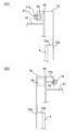
従来例に係る配電盤が列設された状態の正面図である。FIG. 11 is a front view of a state in which conventional switchboards are arranged in a row. 本発明の実施形態に係る配電盤1が列設された状態の正面図である。FIG. 2 is a front view of a state in which the switchboards 1 according to the embodiment of the present invention are arranged in a row. 本発明の実施形態に係る配電盤1が列設された状態の背面図である。FIG. 2 is a rear view of the switchboards 1 according to the embodiment of the present invention arranged in a row. 本発明の実施形態に係る配電盤1が列設された状態の右側面図である。FIG. 2 is a right side view of the switchboards 1 according to the embodiment of the present invention arranged in a row. (A)は、屋根カバー5の断面図(正面視)であり、(B)は、中間部用カバー6の取り付け状態を示す図である。1A is a cross-sectional view (front view) of the roof cover 5, and FIG. 1B is a diagram showing the attached state of the intermediate cover 6. FIG. (C)は、右端部用カバー7aの取り付け状態を示す図であり、(D)は、左端部用カバー7bの取り付け状態を示す図である。1C is a diagram showing the attached state of the right end cover 7a, and FIG. 1D is a diagram showing the attached state of the left end cover 7b. 本発明の実施形態に係る配電盤1の増設作業に関する説明図である。FIG. 2 is an explanatory diagram relating to an expansion work of the switchboard 1 according to the embodiment of the present invention. 本発明の実施形態に係る配電盤1の増設作業に関する説明図である。FIG. 2 is an explanatory diagram relating to an expansion work of the switchboard 1 according to the embodiment of the present invention.

以下、本発明に係る配電盤の屋根構造の実施形態について、図面を参照して説明する。 Below, an embodiment of the roof structure for a switchboard according to the present invention will be described with reference to the drawings.

[構成]
(全体構成)
本発明の実施形態に係る配電盤1は、正面側フレーム2A、背面側フレーム2B、正面側盤扉3A、背面側盤扉3B、及び側面化粧板4などを備える(図2~図4等参照)。なお、配電盤1の内部に収容される制御機器や回路機器などの各種機器についてはその説明を省略している。また、本発明の実施形態では、配電盤1は屋外に設置されるものとしているが、その目的に反しない限り屋内に設置されるものであってもよい。
[composition]
(Overall composition)
The switchboard 1 according to the embodiment of the present invention includes a front frame 2A, a rear frame 2B, a front panel door 3A, a rear panel door 3B, and a side decorative panel 4 (see Figs. 2 to 4, etc.). Note that a description of various devices such as control devices and circuit devices housed inside the switchboard 1 is omitted. In addition, although the switchboard 1 is installed outdoors in the embodiment of the present invention, it may be installed indoors as long as it does not contradict the purpose of the switchboard 1.

また、図2及び図3では、図1と同様、三個の配電盤1が列設された状態を例示しており、正面側からみて右端に位置する配電盤1を右端配電盤1aとし、正面側からみて左端に位置する配電盤1を左端配電盤1cとし、配電盤1aと配電盤1cの間に位置する配電盤1を中間配電盤1bとして説明している。 Also, in Figures 2 and 3, as in Figure 1, three switchboards 1 are illustrated arranged in a row, with the switchboard 1 located at the right end as viewed from the front being the right-end switchboard 1a, the switchboard 1 located at the left end as viewed from the front being the left-end switchboard 1c, and the switchboard 1 located between switchboard 1a and switchboard 1c being the intermediate switchboard 1b.

配電盤1は、正面側フレーム2A及び背面側フレーム2Bにより矩形の筐体として構成され、例えば、その幅は800mm、高さは2300mm、奥行は2000mm程度に設定されている(図2~図4参照)。また、配電盤1は、地上高150mm程度に設定されたチャンネルベース9を介してコンクリートの基礎上に固定される(図4参照)。むろん、これらの寸法はあくまで一例にすぎない。 The switchboard 1 is configured as a rectangular housing made up of a front frame 2A and a rear frame 2B, and is set, for example, to a width of about 800 mm, a height of 2300 mm, and a depth of about 2000 mm (see Figures 2 to 4). The switchboard 1 is also fixed onto a concrete foundation via a channel base 9 that is set about 150 mm above ground (see Figure 4). Of course, these dimensions are merely examples.

正面側フレーム2Aは、鋼板を折り曲げて柱状にした部材を、ネジを用いて溶接レスで直方体に組み上げて構成され、その内部に各種機器が収容される。また、少なくとも配電盤1における正面側が開口しており、その開口に正面側盤扉3Aが取り付けられる。なお、背面側フレーム2B側は、配電盤1における正面側と同様に開口して(背面側フレーム2B内と連通して)、奥行がある機器が収容可能な構成としてもよいし、例えば、仕切り板によって仕切られて、正面側フレーム2A内に収容された各種機器と背面側フレーム2B内に収容された各種機器との配線などに必要な一部分のみが開口する構成としてもよい。 The front frame 2A is constructed by folding steel plates into columns and assembling them into a rectangular parallelepiped shape using screws without welding, and various devices are housed inside. At least the front side of the switchboard 1 is open, and a front panel door 3A is attached to this opening. The rear frame 2B side may be open like the front side of the switchboard 1 (connected to the inside of the rear frame 2B) so that devices with depth can be housed, or it may be divided by a partition plate, and only a portion necessary for wiring between the various devices housed in the front frame 2A and the various devices housed in the rear frame 2B is open.

背面側フレーム2Bは、基本的に正面側フレーム2Aと同様の構成であるが、背面側フレーム2Bでは、少なくとも配電盤1における背面側が開口しており、その開口に背面側盤扉3Bが取り付けられる。なお、配電盤1を列設する際には、一の配電盤1の各フレームと他の配電盤1の各フレームの隣り合う面がネジで強固に締結される。また、配電盤1のフレームは、正面側フレーム2Aと背面側フレーム2Bとに分割されることなく一個のフレーム(例えば、これをフレーム2とする)で構成されるものであってもよい。 The rear frame 2B is basically the same as the front frame 2A, but in the rear frame 2B, at least the rear side of the switchboard 1 is open, and a rear panel door 3B is attached to the opening. When the switchboards 1 are arranged in a row, the adjacent faces of each frame of one switchboard 1 and each frame of another switchboard 1 are firmly fastened with screws. In addition, the frame of the switchboard 1 may be composed of a single frame (for example, this may be called frame 2) without being divided into the front frame 2A and the rear frame 2B.

正面側盤扉3Aは、鋼板を正面側フレーム2A側に折り曲げて袋構造とした扉状の部材で構成され、正面側フレーム2Aの当たり面はパッキンが全周に配された防水構造となっている。また、一端部側(例えば、図2では右端部側)の裏面にヒンジ(図示省略)を有するとともに、他端部側(例えば、図2では左端部側)の表面にハンドル(符号省略)を有し、正面側フレーム2Aの開口(配電盤1の正面側)を開閉自在としている。なお、正面側盤扉3Aの厚みは40mm程度に設定されている(図4参照)。 The front panel door 3A is made of a door-like member in which a steel plate is folded towards the front frame 2A to form a bag structure, and the contact surface of the front frame 2A is waterproofed with gasket arranged all around. It also has a hinge (not shown) on the back surface of one end side (e.g., the right end side in FIG. 2) and a handle (not shown) on the surface of the other end side (e.g., the left end side in FIG. 2), allowing the opening of the front frame 2A (the front side of the switchboard 1) to be opened and closed freely. The thickness of the front panel door 3A is set to about 40 mm (see FIG. 4).

背面側盤扉3Bは、基本的に正面側盤扉3Aと同様の構成であるが、背面側盤扉3Bでは、一端部側(例えば、図3では左端部側)の裏面にヒンジ(図示省略)を有するとともに、他端部側(例えば、図3では右端部側)の表面にハンドル(符号省略)を有し、背面側フレーム2Bの開口(配電盤1の背面側)を開閉自在としている。なお、背面側盤扉3Bの厚みは40mm程度に設定されている(図4参照)。 The rear panel door 3B is basically configured in the same way as the front panel door 3A, but the rear panel door 3B has a hinge (not shown) on the back surface of one end (e.g., the left end in FIG. 3) and a handle (not shown) on the surface of the other end (e.g., the right end in FIG. 3), allowing the opening in the rear frame 2B (the rear side of the switchboard 1) to be opened and closed freely. The thickness of the rear panel door 3B is set to about 40 mm (see FIG. 4).

側面化粧板4は、防水構造を有し、配電盤1の両側面、あるいは配電盤1が列設される場合には両端となる配電盤1の外側面(例えば、図2では配電盤1aの右側面、及び配電盤1cの左側面)に取り付け可能に構成され、正面側フレーム2A及び背面側フレーム2Bの外部露出面をふさぐ。なお、側面化粧板4は、その上部が正面側フレーム2A及び背面側フレーム2Bの上面端を越えて所定長(例えば、50mm程度)上方に延在する構成であり(図4では斜線で図示)、その延在した上部は、後述の端部用カバー7によって覆われる。 The side decorative panels 4 have a waterproof structure and are configured to be attachable to both sides of the switchboard 1, or to the outer sides of the switchboard 1 that are both ends when the switchboards 1 are installed in a row (for example, the right side of the switchboard 1a and the left side of the switchboard 1c in FIG. 2), and cover the externally exposed surfaces of the front frame 2A and the rear frame 2B. The upper part of the side decorative panel 4 extends upward by a predetermined length (for example, about 50 mm) beyond the upper surface ends of the front frame 2A and the rear frame 2B (shown by diagonal lines in FIG. 4), and the extended upper part is covered by the end cover 7 described below.

また、本発明の実施形態では、配電盤1の上部(フレームの上面)に屋根カバー5が設置される。屋根カバー5は、基本的に上述の中間用の屋根カバー502と同様の構成であり、その幅方向の長さは配電盤1の幅方向の長さと同じ(ないし略同じ)となるように設定され、配電盤1の正面側及び背面側のそれぞれで所定長の庇(正面側庇8A及び背面側庇8B)が形成されるように奥行方向の長さが設定されているとともに、配電盤1の正面側から背面側に向かって下り傾斜を有する形状となっている(図4参照)。 In addition, in an embodiment of the present invention, a roof cover 5 is installed on the top of the switchboard 1 (on the top surface of the frame). The roof cover 5 is basically configured in the same way as the intermediate roof cover 502 described above, and its width is set to be the same (or approximately the same) as the width of the switchboard 1. The depth is set so that eaves of a predetermined length (front eaves 8A and rear eaves 8B) are formed on the front and rear sides of the switchboard 1, respectively, and the roof cover 5 has a shape that slopes downward from the front side to the rear side of the switchboard 1 (see FIG. 4).

なお、本発明の実施形態では、屋根カバー5によって形成される配電盤1の正面側庇8A及び背面側庇8Bは、それぞれ配電盤1の端部から200mm程度突出する構成としている(図4参照)。むろん、これらの寸法はあくまで一例にすぎない。例えば、配電盤1の正面側(図4では左側)において保守や点検に必要な範囲は、配電盤1の端部から2000mm程度、配電盤1の背面側(図4では右側)において保守や点検に必要な範囲は、配電盤1の端部から1000mm程度であることから、それを加味して庇の長さを変動させてもよい。 In this embodiment of the present invention, the front eaves 8A and rear eaves 8B of the switchboard 1 formed by the roof cover 5 are each configured to protrude approximately 200 mm from the end of the switchboard 1 (see FIG. 4). Of course, these dimensions are merely examples. For example, the range required for maintenance and inspection on the front side of the switchboard 1 (left side in FIG. 4) is approximately 2000 mm from the end of the switchboard 1, and the range required for maintenance and inspection on the rear side of the switchboard 1 (right side in FIG. 4) is approximately 1000 mm from the end of the switchboard 1, so the length of the eaves may be changed taking this into account.

また、屋根カバー5は、防水構造を有し、配電盤1のフレーム(正面側フレーム2A及び背面側フレーム2B)の上面にボルトで固定される。なお、本発明の実施形態において「防水構造を有する」とは、例えば、構造上、雨滴などの浸入経路となり得る箇所が形成されない設計とすることや、あらかじめ溶接などを行って雨滴などの浸入経路となり得る箇所をふさいでおくことのみならず、雨滴などの浸入経路となり得る箇所にコーキング剤などによる防水処理を事後的に施すことも含まれる。 The roof cover 5 has a waterproof structure and is fixed with bolts to the upper surface of the frame (front frame 2A and rear frame 2B) of the switchboard 1. In the embodiment of the present invention, "having a waterproof structure" includes, for example, not only a design that does not form any points that can serve as infiltration paths for raindrops, etc., or sealing off any points that can serve as infiltration paths for raindrops, etc. by welding in advance, but also the subsequent application of waterproofing treatment using a caulking agent, etc. to any points that can serve as infiltration paths for raindrops, etc.

(屋根カバー5)
ここで、図5(A)を参照して屋根カバー5の構成をさらに説明する。屋根カバー5は、上面部51、底面部52、右端部側の上部プレート53、左端部側の上部プレート54、取付座55などを備える。上面部51、底面部52、上部プレート53(及び屋根カバー5の右側面部)、上部プレート54(及び屋根カバー5の左側面部)は、屋根カバー5の内部が中空となるように鋼板で構成される。また、屋根カバー5の上面側は、上面部51、上部プレート53,54によってコの字を起こした(上向きに開口する凹状の)断面形状を有する。
(Roof cover 5)
Here, the configuration of the roof cover 5 will be further described with reference to Fig. 5 (A). The roof cover 5 comprises an upper surface portion 51, a bottom surface portion 52, an upper plate 53 on the right end side, an upper plate 54 on the left end side, and a mounting seat 55. The upper surface portion 51, the bottom surface portion 52, the upper plate 53 (and the right side portion of the roof cover 5), and the upper plate 54 (and the left side portion of the roof cover 5) are made of steel plates so that the inside of the roof cover 5 is hollow. In addition, the upper surface side of the roof cover 5 has a cross-sectional shape that is U-shaped (concave with an upward opening) created by the upper surface portion 51 and the upper plates 53 and 54.

なお、屋根カバー5は、該屋根カバー5を配電盤1の正面側フレーム2A及び背面側フレーム2Bに固定するための固定部を備えているが、図5(A)では図示を省略している。この固定部は、配電盤1の各フレームの上面と底面部52を、各フレーム側から固定するものであってもよいし、上面部51側から固定するものであってもよい。 The roof cover 5 has fixing parts for fixing the roof cover 5 to the front frame 2A and rear frame 2B of the switchboard 1, but these are not shown in FIG. 5(A). These fixing parts may fix the top and bottom surfaces 52 of each frame of the switchboard 1 from each frame side, or may fix from the top surface 51 side.

上部プレート53,54は、屋根カバー5の左右端部(両端部)において上方に延在し、右端部側の上部プレート53の内側にはナットが溶接された取付座55が所定間隔で複数設けられている。なお、本発明の実施形態では、左端部側の上部プレート54の内側には取付座55を設けない構成としているが、これを設ける構成とし、後述の左端部用カバー7bを、後述の中間部用カバー6や右端部用カバー7aと同様の手法にて取り付け可能にしてもよい。なお、本発明の実施形態では、右端部用カバー7a及び左端部用カバー7bを総称し「端部用カバー7」として説明する場合がある。 The upper plates 53, 54 extend upward at the left and right ends (both ends) of the roof cover 5, and multiple mounting seats 55 with nuts welded are provided at predetermined intervals on the inside of the upper plate 53 on the right end side. Note that in the embodiment of the present invention, the mounting seats 55 are not provided on the inside of the upper plate 54 on the left end side, but it is possible to provide them and make it possible to attach the left end cover 7b described below in the same manner as the middle cover 6 and right end cover 7a described below. Note that in the embodiment of the present invention, the right end cover 7a and the left end cover 7b may be collectively referred to as the "end covers 7".

また、本発明の実施形態では、各屋根カバー5の隣り合う上部プレート53,54(例えば、図2において、配電盤1b上部の屋根カバー5の上部プレート53と配電盤1a上部の屋根カバー5の上部プレート54、及び配電盤1c上部の屋根カバー5の上部プレート53と配電盤1b上部の屋根カバー5の上部プレート54)は、コの字を伏せた(下向きに開口する凹状の)断面形状を有する中間部用カバー6によって被覆される。なお、中間部用カバー6は、後述の右端部用カバー7aと同様、上部プレート53,54の上方のみならず、屋根カバー5の正面側や背面側も40mm程度突出して被覆するように構成されている(図4参照)。これにより、列設された配電盤1間(例えば、図2において、右端配電盤1a・中間配電盤1bの間、及び中間配電盤1b・左端配電盤1cの間)の合わせ目に雨滴などが浸入することを防止している。 In addition, in the embodiment of the present invention, the adjacent upper plates 53, 54 of each roof cover 5 (for example, in FIG. 2, the upper plate 53 of the roof cover 5 on the upper part of the switchboard 1b and the upper plate 54 of the roof cover 5 on the upper part of the switchboard 1a, and the upper plate 53 of the roof cover 5 on the upper part of the switchboard 1c and the upper plate 54 of the roof cover 5 on the upper part of the switchboard 1b) are covered by the middle cover 6 having a cross-sectional shape of an inverted U-shape (concave opening downward). Note that, like the right end cover 7a described later, the middle cover 6 is configured to protrude about 40 mm to cover not only the upper parts 53, 54 but also the front side and the back side of the roof cover 5 (see FIG. 4). This prevents raindrops and the like from entering the joints between the switchboards 1 arranged in a row (for example, in FIG. 2, between the right end switchboard 1a and the middle switchboard 1b, and between the middle switchboard 1b and the left end switchboard 1c).

(中間部用カバー6)
ここで、図5(B)を参照して中間部用カバー6の構成(取り付け状態)をさらに説明する。中間部用カバー6の左側面には、取付座55と対応する各位置にネジ穴62が複数設けられており、中間部用カバー6を隣り合う上部プレート53,54の上方から被せた後、締結用のネジ61をネジ穴62から挿入して取付座55にネジ止めすることにより中間部用カバー6が取り付けられる。
(Middle section cover 6)
5(B) , the configuration (attached state) of the intermediate cover 6 will be further described. A plurality of screw holes 62 are provided on the left side surface of the intermediate cover 6 at positions corresponding to the mounting seats 55. After the intermediate cover 6 is placed over the adjacent upper plates 53, 54 from above, fastening screws 61 are inserted through the screw holes 62 and screwed to the mounting seats 55, thereby attaching the intermediate cover 6.

(端部用カバー7)
また、本発明の実施形態では、右端配電盤1a上の屋根カバー5の右端部側の上部プレート53は、右端部用カバー7aによって被覆される。なお、右端部用カバー7aは、上部プレート53の上方のみならず、屋根カバー5の正面側や背面側も40mm程度突出して被覆するように構成されている(図4参照)。ここで、図6(C)を参照して右端部用カバー7aの構成(取り付け状態)をさらに説明する。
(End Cover 7)
In the embodiment of the present invention, the upper plate 53 on the right end side of the roof cover 5 on the right end switchboard 1a is covered by the right end cover 7a. The right end cover 7a is configured to protrude about 40 mm to cover not only the upper part of the upper plate 53 but also the front side and the back side of the roof cover 5 (see FIG. 4). Here, the configuration (attached state) of the right end cover 7a will be further described with reference to FIG. 6(C).

右端部用カバー7aは、コの字を伏せた(下向きに開口する凹状の)断面形状であり、右端部用カバー7aの左側面には、取付座55と対応する各位置にネジ穴71aが複数設けられ、右端部用カバー7aを上部プレート53の上方から被せた後、締結用のネジ61をネジ穴71aから挿入して取付座55にネジ止めすることにより取り付けられる点は基本的に中間部用カバー6と同様であるが、右端部用カバー7aの右側面には、正面側フレーム2A及び背面側フレーム2Bの上面端を越えて上方に延在された側面化粧板4の上部を覆う垂れ部72aが設けられる点において異なる構成となっている。 The right end cover 7a has a cross-sectional shape that resembles an upside-down U (concave shape that opens downwards), and the left side of the right end cover 7a has multiple screw holes 71a at positions corresponding to the mounting seats 55. After the right end cover 7a is placed over the upper plate 53 from above, the right end cover 7a is attached by inserting fastening screws 61 through the screw holes 71a and screwing it into the mounting seats 55, which is basically the same as the middle cover 6. However, the right end cover 7a has a different configuration in that the right side of the right end cover 7a has a hanging portion 72a that covers the upper part of the side decorative panel 4 that extends upward beyond the top edges of the front frame 2A and rear frame 2B.

すなわち、列設された配電盤1a~1cの右端部側では、屋根部分とフレーム部分の合わせ目(屋根カバー5の底面部52と、正面側フレーム2A及び背面側フレーム2Bの上面との間)が側面化粧板4の上部(延在させた部分)によって覆われ、さらにその側面化粧板4の上部が右端部用カバー7aによって上方から覆われるように構成されている。これにより、右端配電盤1aの右端側において、屋根部分とフレーム部分の合わせ目に雨滴などが浸入することを防止している。なお、垂れ部72aには、さらに所定位置にL字アングル73aが設けられ、その防水効果を高めている。 That is, at the right end of the row of switchboards 1a to 1c, the seam between the roof and frame (between the bottom surface 52 of roof cover 5 and the upper surfaces of front frame 2A and rear frame 2B) is covered by the upper part (extended part) of side decorative plate 4, and the upper part of the side decorative plate 4 is further covered from above by right end cover 7a. This prevents raindrops and the like from entering the seam between the roof and frame at the right end of right-end switchboard 1a. An L-shaped angle 73a is also provided at a specified position on the hanging part 72a to enhance its waterproofing effect.

また、本発明の実施形態では、左端配電盤1c上の屋根カバー5の左端部側の上部プレート54は、左端部用カバー7bによって被覆される。なお、左端部用カバー7bは、上述の右端部用カバー7aと同様、上部プレート54の上方のみならず、屋根カバー5の正面側や背面側も40mm程度突出して被覆するように構成されている(図4参照)。ここで、図6(D)を参照して左端部用カバー7bの構成(取り付け状態)をさらに説明する。 In addition, in this embodiment of the present invention, the upper plate 54 on the left end side of the roof cover 5 on the left end switchboard 1c is covered by the left end cover 7b. Note that, like the right end cover 7a described above, the left end cover 7b is configured to protrude and cover not only the upper part of the upper plate 54 but also the front and back sides of the roof cover 5 by about 40 mm (see FIG. 4). Here, the configuration (attached state) of the left end cover 7b will be further explained with reference to FIG. 6(D).

左端部用カバー7bは、コの字を伏せた(下向きに開口する凹状の)断面形状であって、その左側面において、側面化粧板4の上部を覆う垂れ部72bが設けられ(また該垂れ部72bにはL字アングル73bが設けられ)、これにより、左端配電盤1cの左端側(列設された配電盤1a~1cの左端部側)において、屋根部分とフレーム部分の合わせ目に雨滴などが浸入することを防止している点は基本的に右端部用カバー7aと同様である。 The left end cover 7b has a cross-sectional shape resembling an upside-down U (a concave shape that opens downwards), and on its left side is provided a hanging portion 72b that covers the upper part of the side decorative panel 4 (and an L-shaped angle 73b is provided on said hanging portion 72b), which prevents raindrops and the like from entering the seam between the roof and frame on the left end side of the left end distribution board 1c (the left end side of the row of distribution boards 1a-1c), which is basically the same as the right end cover 7a.

もっとも、屋根カバー5の上部プレート54には取付座55を設けない構成としているので(図5(A)参照)、左端部用カバー7bは右端部用カバー7aとは異なる手法で取り付けられる。なお、上述の如く、上部プレート54の内側にも取付座55を設けるようにし、左端部用カバー7bを右端部用カバー7aと同様に(勝手違いに)構成して取り付けられるものとしてもよい。また、上部プレート53の内側にも取付座55を設けないようにし、右端部用カバー7aを左端部用カバー7bと同様に(勝手違いに)構成して取り付けられるものとしてもよい。すなわち、右端部用カバー7a及び左端部用カバー7bは、左右対称となる端部用カバー7として構成されるものであってもよい。 However, since the upper plate 54 of the roof cover 5 is configured without the mounting seat 55 (see FIG. 5(A)), the left end cover 7b is attached in a different manner to the right end cover 7a. As described above, the mounting seat 55 may also be provided on the inside of the upper plate 54, and the left end cover 7b may be configured and attached in the same manner as the right end cover 7a (opposite sides). Also, the mounting seat 55 may not be provided on the inside of the upper plate 53, and the right end cover 7a may be configured and attached in the same manner as the left end cover 7b (opposite sides). In other words, the right end cover 7a and the left end cover 7b may be configured as end covers 7 that are symmetrical on the left and right.

左端部用カバー7bの右側面には、所定間隔で複数のネジ穴71bが設けられる。また、その内側には各ネジ穴71bに対応する位置に複数のナット75が溶接で取り付けられる。また、左端部用カバー7bの左側面の内側には、各ナット75に対応する対向位置に複数の当たり部76が溶接で取り付けられる。左端部用カバー7bを上部プレート54の上方から被せ、押止用のネジ74をネジ穴71bから挿入してナット75に螺嵌していくと、ネジ74の先端と当たり部76とによって上部プレート54の当接面が挟持され、固定される。 The right side surface of the left end cover 7b has a number of screw holes 71b at a predetermined interval. A number of nuts 75 are attached by welding to the inside of the cover at positions corresponding to the screw holes 71b. A number of abutments 76 are attached by welding to the inside of the left side surface of the left end cover 7b at positions opposite the nuts 75. When the left end cover 7b is placed over the upper plate 54 from above and the retaining screw 74 is inserted through the screw hole 71b and screwed into the nut 75, the abutment surface of the upper plate 54 is clamped and fixed by the tip of the screw 74 and the abutment 76.

[作用]
上記のように構成された配電盤1の屋根構造の作用を、図7及び図8を用いて説明する。なお、図7及び図8では、一個の配電盤1(配電盤1a)が設置された状態から、さらに一個の配電盤1(配電盤1b)を増設する際の作業工程の一例を示している。
[Action]
The function of the roof structure of the switchboard 1 configured as above will be described with reference to Fig. 7 and Fig. 8. Fig. 7 and Fig. 8 show an example of a work process when adding another switchboard 1 (switchboard 1b) to a state where one switchboard 1 (switchboard 1a) has already been installed.

図7(1)では、屋根カバー5が設置され、屋根カバー5の上部プレート53に右端部用カバー7aが取り付けられ、屋根カバー5の上部プレート54に左端部用カバー7bが取り付けられた配電盤1aが設置された状態を示している。 Figure 7 (1) shows the state in which the roof cover 5 is installed, the right end cover 7a is attached to the upper plate 53 of the roof cover 5, and the left end cover 7b is attached to the upper plate 54 of the roof cover 5, and the distribution board 1a is installed.

配電盤1aの左側に配電盤1bを増設する場合、まず、配電盤1aの屋根カバー5に取り付けられた左端部用カバー7bを取り外す。具体的には、ネジ穴71bから挿入されていたネジ74を押止方向とは逆方向に回し、上部プレート54を、ネジ74の先端と当たり部76との挟持から解放する(図6(D)参照)。なお、図示は省略しているが、配電盤1aの左側面に取り付けられていた側面化粧板4も取り外される。 When adding a switchboard 1b to the left of the switchboard 1a, first remove the left end cover 7b attached to the roof cover 5 of the switchboard 1a. Specifically, turn the screw 74 inserted through the screw hole 71b in the opposite direction to the retaining direction, and release the upper plate 54 from being clamped between the tip of the screw 74 and the contact portion 76 (see FIG. 6(D)). Although not shown in the figure, the side decorative panel 4 attached to the left side of the switchboard 1a is also removed.

次いで、図7(2)に示すように、配電盤1aの左側に配電盤1bを設置した後、これらのフレーム同士を連結する。なお、図示は省略しているが、配電盤1bの左側面には側面化粧板4が取り付けられる。次いで、図8(3)に示すように、配電盤1aの屋根カバー5と配電盤1bの屋根カバー5との合わせ目に中間部用カバー6を取り付ける。具体的には、中間部用カバー6の左側面に設けられたネジ穴62にネジ61を挿入し、ネジ61を締結方向に回して配電盤1bの屋根カバー5の上部プレート53に設けられた取付座55に締結する(図5(B)参照)。 Next, as shown in FIG. 7(2), after placing the switchboard 1b on the left side of the switchboard 1a, these frames are connected to each other. Although not shown, a side decorative panel 4 is attached to the left side of the switchboard 1b. Next, as shown in FIG. 8(3), the intermediate cover 6 is attached to the joint between the roof cover 5 of the switchboard 1a and the roof cover 5 of the switchboard 1b. Specifically, a screw 61 is inserted into a screw hole 62 provided on the left side of the intermediate cover 6, and the screw 61 is turned in the fastening direction to fasten it to the mounting seat 55 provided on the upper plate 53 of the roof cover 5 of the switchboard 1b (see FIG. 5(B)).

最後に、図8(4)に示すように、配電盤1bの屋根カバー5に左端部用カバー7bを取り付ける。具体的には、左端部用カバー7bの右側面に設けられたネジ穴71bからネジ74を挿入し、ネジ74の先端と当たり部76とによって配電盤1b左端側の上部プレート54が挟持されて固定されるまでネジ74を押止方向に回す(図6(D)参照)。なお、図8(3)の作業工程と図8(4)の作業工程はその順序が逆であってもよい。 Finally, as shown in FIG. 8(4), the left end cover 7b is attached to the roof cover 5 of the switchboard 1b. Specifically, a screw 74 is inserted through a screw hole 71b provided on the right side surface of the left end cover 7b, and the screw 74 is turned in the pressing direction until the upper plate 54 on the left end side of the switchboard 1b is clamped and fixed by the tip of the screw 74 and the contact portion 76 (see FIG. 6(D)). Note that the order of the work steps in FIG. 8(3) and FIG. 8(4) may be reversed.

ここで、図示は省略しているが、例えば、既設の配電盤1の右側に配電盤1を増設する場合の、右端部用カバー7aの取り外し及び取り付け作業についても説明する。右端部用カバー7aを取り外す場合には、ネジ穴71aから挿入されていたネジ61を締結方向とは逆方向に回し、取付座55との締結を解除する(図6(C)参照)。また、右端部用カバー7aを取り付ける場合には、ネジ穴71aにネジ61を挿入し、ネジ61を締結方向に回して取付座55に締結する(図6(C)参照)。 Although not shown in the figures, the removal and installation of the right end cover 7a will be described for the case where an additional switchboard 1 is installed on the right side of an existing switchboard 1. When removing the right end cover 7a, the screw 61 inserted through the screw hole 71a is turned in the opposite direction to the fastening direction to release the fastening to the mounting base 55 (see FIG. 6(C)). When installing the right end cover 7a, the screw 61 is inserted into the screw hole 71a and turned in the fastening direction to fasten the screw 61 to the mounting base 55 (see FIG. 6(C)).

本発明の実施形態に係る配電盤1の屋根構造では、配電盤1を増設する際、右端部用カバー7aや左端部用カバー7bを中間部用カバー6に交換する作業を行えばよく(むろん、列設した配電盤1を撤去する際にはその逆の作業を行えばよく)、屋根カバー5を交換する作業が必要ない。すなわち、大掛かりな増設工事は不要となる。また、これに加え、配電盤1がどこに列設されるものであっても屋根カバー5の構成を共通化することできる。 In the roof structure of the switchboard 1 according to the embodiment of the present invention, when adding a switchboard 1, it is sufficient to replace the right end cover 7a and the left end cover 7b with the middle cover 6 (of course, the reverse is done when removing a switchboard 1 that has been installed in a row), and there is no need to replace the roof cover 5. In other words, there is no need for large-scale expansion work. In addition, the configuration of the roof cover 5 can be made common regardless of where the switchboard 1 is installed in a row.

また、上述の如く、中間部用カバー6は、その左側面のネジ穴62からネジ61を挿入し、上部プレート53の左側面に設けられた取付座55にネジ止めすれば屋根カバー5への固定が可能となっている(図5(B)参照)。また、右端部用カバー7aは、その左側面のネジ穴71aからネジ61を挿入し、上部プレート53の左側面に設けられた取付座55にネジ止めすれば屋根カバー5への固定が可能となっている(図6(C)参照)。また、左端部用カバー7bは、その右側面のネジ穴71bからネジ74を挿入してナット75に螺嵌させ、ネジ74の先端と当たり部76とによって上部プレート54を挟持すれば屋根カバー5への固定が可能となっている(図6(D)参照)。すなわち、上部プレート53,54自体に貫通穴(貫通部)を設けることなくそれらの固定が可能となっている。したがって、そのような貫通穴から雨滴などが浸入することを防止できるし、防水処理を簡素化することもできるようになる。 As described above, the middle cover 6 can be fixed to the roof cover 5 by inserting the screw 61 through the screw hole 62 on the left side and screwing it into the mounting seat 55 on the left side of the upper plate 53 (see FIG. 5B). The right end cover 7a can be fixed to the roof cover 5 by inserting the screw 61 through the screw hole 71a on the left side and screwing it into the mounting seat 55 on the left side of the upper plate 53 (see FIG. 6C). The left end cover 7b can be fixed to the roof cover 5 by inserting the screw 74 through the screw hole 71b on the right side and screwing it into the nut 75, and clamping the upper plate 54 between the tip of the screw 74 and the contact portion 76 (see FIG. 6D). That is, the upper plates 53 and 54 can be fixed without providing a through hole (through portion) in the plates themselves. Therefore, it is possible to prevent raindrops and the like from entering through such a through hole, and it is also possible to simplify the waterproofing treatment.

さらに、中間部用カバー6、右端部用カバー7a、及び左端部用カバー7bのいずれもがネジ止めするだけで既定位置に設置できるので、増設時に現場で調整作業を行う必要も生じにくくなる。 Furthermore, the middle cover 6, right end cover 7a, and left end cover 7b can all be installed in the designated position simply by screwing them in place, reducing the need for on-site adjustment work when adding additional units.

なお、本発明の実施形態に係る配電盤1の屋根構造では、正面側から背面側に向かって下り傾斜を有する屋根カバー5の上面部51と、中間部用カバー6の側面と、右端部用カバー7aの垂れ部72aが設けられていない側面又は左端部用カバー7bの垂れ部72bが設けられていない側面とで、屋根カバー5上の雨滴を後方に排出する樋部が形成されることとなる。 In the roof structure of the switchboard 1 according to the embodiment of the present invention, a gutter that drains raindrops on the roof cover 5 to the rear is formed by the top surface 51 of the roof cover 5, which slopes downward from the front side to the rear side, the side of the middle cover 6, and the side of the right end cover 7a that does not have the hanging portion 72a or the side of the left end cover 7b that does not have the hanging portion 72b.

この点、図1で説明した従来例では、中間用の屋根カバー502上の雨滴は後方に排出され得るものの、右端用の屋根カバー501や左端用の屋根カバー503上の雨滴は後方のみならず、それぞれ右方や左方にも排出され得るため、水たまりの発生箇所が増加して浸水リスクが高まる、あるいは排水路を背面側以外にも設ける必要があるなどといった問題が生じていたが、本発明の実施形態に係る配電盤1の屋根構造では、そのような問題は生じなくなる。 In this regard, in the conventional example described in FIG. 1, although raindrops on the middle roof cover 502 can be drained to the rear, raindrops on the right-end roof cover 501 and the left-end roof cover 503 can be drained not only to the rear but also to the right and left, respectively, resulting in problems such as an increase in the number of places where puddles form, increasing the risk of flooding, or the need to provide drainage channels on other sides besides the back side. However, with the roof structure of the switchboard 1 according to the embodiment of the present invention, such problems do not arise.

[効果]
ここまで説明したように、本発明の実施形態に係る配電盤1の屋根構造では、屋根カバー5の両端部において上方に延在する上部プレート53及び上部プレート54は、列設された複数の配電盤1において中間に位置する場合には、隣り合う上部プレート54又は上部プレート53とともに中間部用カバー6で上方から覆われ、列設された複数の配電盤1において端部に位置する場合には端部用カバー7で上方から覆われ、中間部用カバー6及び端部用カバー7は、ともに防水構造を有して着脱可能に構成される。これにより、配電盤1の防水性を確保しながらも増設する対応を容易とし、かつ、そのコストも低減することができる。
[effect]
As described above, in the roof structure of the switchboard 1 according to the embodiment of the present invention, the upper plates 53 and 54 extending upward at both ends of the roof cover 5 are covered from above by the middle cover 6 together with the adjacent upper plates 54 or 53 when located at the middle of the multiple switchboards 1 arranged in a row, and are covered from above by the end cover 7 when located at the end of the multiple switchboards 1 arranged in a row, and both the middle cover 6 and the end cover 7 have a waterproof structure and are configured to be removable. This makes it easy to expand the switchboard 1 while ensuring its waterproofness, and also reduces the cost.

また、本発明の実施形態に係る配電盤1の屋根構造では、中間部用カバー6及び端部用カバー7は、ともに上部プレート53,54に貫通穴を設けることなく屋根カバー5に固定可能に構成される。これにより、配電盤1の防水性や増設時の作業効率をさらに高めることができるため、上述の効果をより顕著なものとすることができる。 In addition, in the roof structure of the switchboard 1 according to the embodiment of the present invention, the middle cover 6 and the end cover 7 are both configured to be fixed to the roof cover 5 without providing through holes in the upper plates 53, 54. This further improves the waterproofing of the switchboard 1 and the work efficiency during expansion, making the above-mentioned effects even more pronounced.

また、本発明の実施形態に係る配電盤1の屋根構造では、屋根カバー5は、配電盤1の正面側から背面側に向かって下り傾斜を有する形状であり、屋根カバー5と、中間部用カバー6と、端部用カバー7とで屋根カバー5上の雨滴を後方に排出する樋部が形成される。これにより、配電盤1の排水性などをさらに高めることができるため、上述の効果をより顕著なものとすることができる。 In addition, in the roof structure of the switchboard 1 according to the embodiment of the present invention, the roof cover 5 has a shape that slopes downward from the front side to the rear side of the switchboard 1, and the roof cover 5, the middle cover 6, and the end cover 7 form a gutter that drains raindrops on the roof cover 5 to the rear. This can further improve the drainage properties of the switchboard 1, making the above-mentioned effects even more pronounced.

以上、本発明のいくつかの実施形態を説明したが、これらの実施形態は、例として提示したものであり、発明の範囲を限定することは意図していない。また、これら新規な実施形態は、その他の様々な形態で実施されることが可能であり、発明の要旨を逸脱しない範囲で、種々の省略、置き換え、変更を行うことができる。これら実施形態やその変形は、発明の範囲や要旨に含まれるとともに、特許請求の範囲に記載された発明とその均等の範囲に含まれる。 Although several embodiments of the present invention have been described above, these embodiments are presented as examples and are not intended to limit the scope of the invention. Furthermore, these novel embodiments can be implemented in various other forms, and various omissions, substitutions, and modifications can be made without departing from the gist of the invention. These embodiments and their modifications are included within the scope and gist of the invention, and are included in the scope of the invention and its equivalents as set forth in the claims.

1…配電盤、2A…正面側フレーム、2B…背面側フレーム、3A…正面側盤扉、3B…背面側盤扉、4…側面化粧板、5…屋根カバー、6…中間部用カバー、7…端部用カバー、7a…右端部用カバー、7b…左端部用カバー、8A…正面側庇、8B…背面側庇、9…チャンネルベース、51…上面部、52…底面部、53,54…上部プレート、55…取付座、61…ネジ、62,71a,71b…ネジ穴、72a,72b…垂れ部、73a,73b…L字アングル、74…ネジ、75…ナット、76…当たり部、501,502,503…屋根カバー
Reference Signs List 1: distribution board, 2A: front frame, 2B: rear frame, 3A: front panel door, 3B: rear panel door, 4: side decorative panel, 5: roof cover, 6: middle cover, 7: end cover, 7a: right end cover, 7b: left end cover, 8A: front eaves, 8B: rear eaves, 9: channel base, 51: upper surface, 52: bottom surface, 53, 54: upper plate, 55: mounting base, 61: screws, 62, 71a, 71b: screw holes, 72a, 72b: hanging portions, 73a, 73b: L-shaped angles, 74: screws, 75: nuts, 76: contact portions, 501, 502, 503: roof cover

Claims (1)

屋外において複数列設される配電盤の屋根構造において、
前記配電盤は、各種機器がその内部に収容されるフレームを有し、該フレームの上部に屋根カバーが設置される構成であり、
前記屋根カバーは、両端部において上方に延在する上部プレートを有し、
前記上部プレートは、列設された複数の前記配電盤において中間に位置する場合には、隣り合う前記上部プレートとともに中間部用カバーで上方から覆われ、列設された複数の前記配電盤において端部に位置する場合には端部用カバーで上方から覆われ、
前記中間部用カバー及び端部用カバーは、ともに防水構造を有して着脱可能に構成され、かつ、ともに前記上部プレートに貫通穴を設けることなく前記屋根カバーに固定可能に構成され、
前記上部プレートは、前記屋根カバーの一端部側で上方に延在する第1上部プレートと、前記屋根カバーの他端部側で上方に延在する第2上部プレートからなり、
前記端部用カバーは、列設された複数の前記配電盤において一端部側を覆う第1端部用カバーと、列設された複数の前記配電盤において他端部側を覆う第2端部用カバーからなり、
前記中間部用カバー及び前記第1端部用カバーは、前記第1上部プレートの内側面に設けた複数の取付座にネジ止めされることにより前記屋根カバーに固定され、
前記第2端部用カバーは、前記第2端部用カバーの内部において前記第2上部プレートの外側面に当接する位置に設けた複数の当たり部と、前記第2端部用カバーの外部から前記第2上部プレートの内側面に向かって挿入された押止用ネジの先端とで前記第2上部プレートを挟持することにより前記屋根カバーに固定されることを特徴とする配電盤の屋根構造。
In a roof structure for a switchboard that is installed in a row outdoors,
The switchboard has a frame in which various devices are housed, and a roof cover is installed on an upper portion of the frame,
The roof cover has an upper plate extending upwardly at each end;
When the upper plate is located at the middle of the plurality of switchboards arranged in a row, the upper plate is covered from above with a middle cover together with the adjacent upper plates, and when the upper plate is located at the end of the plurality of switchboards arranged in a row, the upper plate is covered from above with an end cover;
the intermediate cover and the end cover are both configured to be waterproof and detachable , and are both configured to be fixed to the roof cover without providing a through hole in the upper plate;
The upper plate includes a first upper plate extending upward from one end of the roof cover and a second upper plate extending upward from the other end of the roof cover,
The end cover includes a first end cover that covers one end side of the plurality of switchboards arranged in a row, and a second end cover that covers the other end side of the plurality of switchboards arranged in a row,
the intermediate cover and the first end cover are fixed to the roof cover by being screwed to a plurality of mounting seats provided on an inner surface of the first upper plate,
A roof structure for a distribution board, characterized in that the second end cover is fixed to the roof cover by clamping the second upper plate between a plurality of abutment portions provided at a position inside the second end cover that abuts the outer surface of the second upper plate and the tip of a retaining screw inserted from the outside of the second end cover toward the inner surface of the second upper plate .
JP2023080519A 2023-05-16 2023-05-16 Roof structure of outdoor distribution board Active JP7588944B1 (en)

Priority Applications (1)

Application Number Priority Date Filing Date Title
JP2023080519A JP7588944B1 (en) 2023-05-16 2023-05-16 Roof structure of outdoor distribution board

Applications Claiming Priority (1)

Application Number Priority Date Filing Date Title
JP2023080519A JP7588944B1 (en) 2023-05-16 2023-05-16 Roof structure of outdoor distribution board

Publications (2)

Publication Number Publication Date
JP7588944B1 true JP7588944B1 (en) 2024-11-25
JP2024167149A JP2024167149A (en) 2024-12-03

Family

ID=93587996

Family Applications (1)

Application Number Title Priority Date Filing Date
JP2023080519A Active JP7588944B1 (en) 2023-05-16 2023-05-16 Roof structure of outdoor distribution board

Country Status (1)

Country Link
JP (1) JP7588944B1 (en)

Also Published As

Publication number Publication date
JP2024167149A (en) 2024-12-03

Similar Documents

Publication Publication Date Title
EP2169139A1 (en) Fixing structure of solar battery module, frame for the solar battery module, and fixing member
JP2019190269A (en) Solar panel installation frame
AU2015396638B2 (en) Electrical connection device for a photovoltaic system
EP1355019B1 (en) Awning installing device
PL207562B1 (en) Drainage and sealing system, and panel set-up containing this system
JP3395597B2 (en) Solar cell frame
JP2018048525A (en) Opening/closing device for construction and waterproof structure
JP2024167149A (en) Roof structure of outdoor distribution board
JP3504108B2 (en) Roof waterproof structure with a rooftop installation base
JP3504109B2 (en) Roof waterproof structure with a rooftop installation base
JP2011202504A (en) Supporting member for exterior construction
JPH10317598A (en) Roof with rooftop equipment such as solar cell modules
JP2008095418A (en) Exterior construction support member and exterior structure using the support member
JP2514301B2 (en) Solar panel mounting structure
JP2001156322A (en) Waterproof structure of solar battery panel
JP5101857B2 (en) Exterior construction support member and exterior structure using the support member
JP2005299345A (en) Sealing structure of extrusion molding cement plate joint, water drip material for extrusion molding cement plate and outer wall non-scaffold construction method using extrusion molding cement plate
JP4311817B2 (en) Joint seal structure between roof panels with solar cells
JP2018048524A (en) Waterproof panel in open/close device for building and assembly method of the waterproof panel
KR102966038B1 (en) Waterproof Clamp Structure
JP2005282124A (en) Panel installing structure
JP7748272B2 (en) Top surface weatherproofing structure of building unit
JP2000240241A (en) Solar cell panel fitting structure
CN218406086U (en) Fixed bearing structure and building integrated photovoltaic structure
JP3650964B2 (en) balcony

Legal Events

Date Code Title Description
A621 Written request for application examination

Free format text: JAPANESE INTERMEDIATE CODE: A621

Effective date: 20230516

A131 Notification of reasons for refusal

Free format text: JAPANESE INTERMEDIATE CODE: A131

Effective date: 20240709

A521 Request for written amendment filed

Free format text: JAPANESE INTERMEDIATE CODE: A523

Effective date: 20240823

TRDD Decision of grant or rejection written
A01 Written decision to grant a patent or to grant a registration (utility model)

Free format text: JAPANESE INTERMEDIATE CODE: A01

Effective date: 20241112

A61 First payment of annual fees (during grant procedure)

Free format text: JAPANESE INTERMEDIATE CODE: A61

Effective date: 20241112

R150 Certificate of patent or registration of utility model

Ref document number: 7588944

Country of ref document: JP

Free format text: JAPANESE INTERMEDIATE CODE: R150