JP7588942B2 - Method of charging reduced iron into electric furnace - Google Patents
Method of charging reduced iron into electric furnace Download PDFInfo
- Publication number
- JP7588942B2 JP7588942B2 JP2021208485A JP2021208485A JP7588942B2 JP 7588942 B2 JP7588942 B2 JP 7588942B2 JP 2021208485 A JP2021208485 A JP 2021208485A JP 2021208485 A JP2021208485 A JP 2021208485A JP 7588942 B2 JP7588942 B2 JP 7588942B2
- Authority
- JP
- Japan
- Prior art keywords
- reduced iron
- electric furnace
- charging
- melting
- iron
- Prior art date
- Legal status (The legal status is an assumption and is not a legal conclusion. Google has not performed a legal analysis and makes no representation as to the accuracy of the status listed.)
- Active
Links
- XEEYBQQBJWHFJM-UHFFFAOYSA-N Iron Chemical compound [Fe] XEEYBQQBJWHFJM-UHFFFAOYSA-N 0.000 title claims description 173
- 238000000034 method Methods 0.000 title claims description 34
- 239000002994 raw material Substances 0.000 claims description 48
- 229910000831 Steel Inorganic materials 0.000 claims description 44
- 239000010959 steel Substances 0.000 claims description 44
- 230000008018 melting Effects 0.000 claims description 32
- 238000002844 melting Methods 0.000 claims description 32
- 239000002184 metal Substances 0.000 claims description 13
- 229910052751 metal Inorganic materials 0.000 claims description 13
- OKTJSMMVPCPJKN-UHFFFAOYSA-N Carbon Chemical compound [C] OKTJSMMVPCPJKN-UHFFFAOYSA-N 0.000 claims description 7
- 229910052799 carbon Inorganic materials 0.000 claims description 7
- 238000004519 manufacturing process Methods 0.000 claims description 4
- 239000004484 Briquette Substances 0.000 claims 1
- 239000007787 solid Substances 0.000 description 34
- 229910052742 iron Inorganic materials 0.000 description 14
- UQSXHKLRYXJYBZ-UHFFFAOYSA-N Iron oxide Chemical compound [Fe]=O UQSXHKLRYXJYBZ-UHFFFAOYSA-N 0.000 description 12
- 239000002893 slag Substances 0.000 description 11
- 239000000203 mixture Substances 0.000 description 8
- 238000004088 simulation Methods 0.000 description 8
- 238000010586 diagram Methods 0.000 description 6
- 238000002474 experimental method Methods 0.000 description 5
- 238000010079 rubber tapping Methods 0.000 description 5
- 238000007664 blowing Methods 0.000 description 4
- 230000000052 comparative effect Effects 0.000 description 4
- 238000010891 electric arc Methods 0.000 description 4
- 239000000463 material Substances 0.000 description 4
- 238000009628 steelmaking Methods 0.000 description 4
- 230000004907 flux Effects 0.000 description 3
- 239000007789 gas Substances 0.000 description 3
- 238000007670 refining Methods 0.000 description 3
- 229910001341 Crude steel Inorganic materials 0.000 description 2
- MYMOFIZGZYHOMD-UHFFFAOYSA-N Dioxygen Chemical compound O=O MYMOFIZGZYHOMD-UHFFFAOYSA-N 0.000 description 2
- QVGXLLKOCUKJST-UHFFFAOYSA-N atomic oxygen Chemical compound [O] QVGXLLKOCUKJST-UHFFFAOYSA-N 0.000 description 2
- 230000033228 biological regulation Effects 0.000 description 2
- 230000007423 decrease Effects 0.000 description 2
- 229910001882 dioxygen Inorganic materials 0.000 description 2
- 239000012768 molten material Substances 0.000 description 2
- 229910052760 oxygen Inorganic materials 0.000 description 2
- 239000001301 oxygen Substances 0.000 description 2
- 230000000704 physical effect Effects 0.000 description 2
- 238000004064 recycling Methods 0.000 description 2
- 238000003756 stirring Methods 0.000 description 2
- 238000004458 analytical method Methods 0.000 description 1
- 230000015572 biosynthetic process Effects 0.000 description 1
- 238000004364 calculation method Methods 0.000 description 1
- 239000000356 contaminant Substances 0.000 description 1
- 238000005261 decarburization Methods 0.000 description 1
- 230000006866 deterioration Effects 0.000 description 1
- 230000000694 effects Effects 0.000 description 1
- 239000012530 fluid Substances 0.000 description 1
- 229910002804 graphite Inorganic materials 0.000 description 1
- 239000010439 graphite Substances 0.000 description 1
- 230000002452 interceptive effect Effects 0.000 description 1
- 239000000155 melt Substances 0.000 description 1
- 239000005416 organic matter Substances 0.000 description 1
- 239000002245 particle Substances 0.000 description 1
- 239000012071 phase Substances 0.000 description 1
- 239000011435 rock Substances 0.000 description 1
- 239000007790 solid phase Substances 0.000 description 1
- 238000007711 solidification Methods 0.000 description 1
- 230000008023 solidification Effects 0.000 description 1
Classifications
-
- Y—GENERAL TAGGING OF NEW TECHNOLOGICAL DEVELOPMENTS; GENERAL TAGGING OF CROSS-SECTIONAL TECHNOLOGIES SPANNING OVER SEVERAL SECTIONS OF THE IPC; TECHNICAL SUBJECTS COVERED BY FORMER USPC CROSS-REFERENCE ART COLLECTIONS [XRACs] AND DIGESTS
- Y02—TECHNOLOGIES OR APPLICATIONS FOR MITIGATION OR ADAPTATION AGAINST CLIMATE CHANGE
- Y02P—CLIMATE CHANGE MITIGATION TECHNOLOGIES IN THE PRODUCTION OR PROCESSING OF GOODS
- Y02P10/00—Technologies related to metal processing
- Y02P10/20—Recycling
Landscapes
- Refinement Of Pig-Iron, Manufacture Of Cast Iron, And Steel Manufacture Other Than In Revolving Furnaces (AREA)
- Vertical, Hearth, Or Arc Furnaces (AREA)
Description
本発明は、アーク式の電気炉にて還元鉄を用いて溶鋼を製造するにあたり、電気炉へ還元鉄を装入する技術に関する。 The present invention relates to a technique for charging reduced iron into an electric arc furnace when producing molten steel using reduced iron in the electric arc furnace.
従来、電気炉で鋼を製造するに際しては、スクラップや還元鉄などの鉄源をフラックスと一緒に炉内に装入し、アークにより鉄源を加熱し溶解している。その鉄源が十分に溶解した後、ランスより酸素ガスを溶鋼に吹き込みながら脱りんを行っている。
近年では、CO2の削減やリサイクルの観点から電気炉による製鋼法の重要性が再認識されつつある。このようなことから、電気炉の操業において、スクラップや還元鉄などを溶解原料として用いられることが考えられる。
Conventionally, when producing steel in an electric furnace, iron sources such as scrap and reduced iron are charged into the furnace together with flux, and the iron sources are heated and melted by an electric arc. After the iron sources are fully melted, dephosphorization is performed by blowing oxygen gas into the molten steel from a lance.
In recent years, the importance of steelmaking using electric furnaces has been reaffirmed from the perspective of reducing CO2 emissions and recycling. For this reason, it is considered that scrap and reduced iron can be used as melting materials in the operation of electric furnaces.
特許文献1は、電気炉で酸化鉄を含有する原料を溶解するにあたり鉄歩留の高い方法が開示されている。具体的には、電極と攪拌用インペラーと底吹き羽口を有する電気炉において、これらの位置関係を適正化(簡単に記載すると羽口を電極に近い側に設置)することで、酸化鉄含有鉄原料を用いても鉄歩留を高くできるものとされている。
特許文献2は、アーク炉において還元鉄を原料として用いるときの温度制御方法が開示されている。具体的には、還元鉄はスラグに装入し、スラグ温度低下時は電力を増加させて電極を上昇させ、溶鋼温度低下時は電力を増加させて電極を降下させることとされている。
Patent Document 1 discloses a method for achieving a high iron yield when melting raw materials containing iron oxide in an electric furnace. Specifically, it is said that by optimizing the positional relationship of an electric furnace having electrodes, a stirring impeller, and a bottom-blowing tuyeres (simply put, by placing the tuyeres closer to the electrodes), it is possible to increase the iron yield even when using raw materials containing iron oxide.
Patent Document 2 discloses a temperature control method when reduced iron is used as a raw material in an arc furnace. Specifically, the reduced iron is charged into slag, and when the slag temperature drops, the power is increased to raise the electrodes, and when the molten steel temperature drops, the power is increased to lower the electrodes.
特許文献3は、電気炉の設備およびそれを用いた製造方法が開示されている。具体的には、投入用物質(鉄含有物、炭素含有物、フラックス、処理済み有機物の軽量分画および数種のガス)を供給し、予熱用シャフト、投入用シャフト、炉容器、デカンター容器、精錬用容器のいずれか一つ又は複数に配された、プロセス生産物(粗鋼、スラグおよび排ガス)を溶融、精錬、加熱を行うとともに、前記プロセス生産物の排出することを、精錬用容器から粗鋼を不連続的に取り出しつつ、プラントの各部分の直前直後でプロセス過程に影響を与えたり、妨げたりすることなく、連続的または半連続的に行うことが好ましいとされている。また、精錬用容器内の金属浴の高さは、再混合を避けるように、炉容器内の金属浴高さよりも低く保たれることが好ましいとされている。 Patent Document 3 discloses an electric furnace and a manufacturing method using the same. Specifically, it is preferable to supply input materials (iron-containing material, carbon-containing material, flux, light fraction of treated organic matter, and several types of gases), melt, refine, and heat process products (crude steel, slag, and exhaust gas) arranged in one or more of a preheating shaft, an input shaft, a furnace vessel, a decanter vessel, and a refining vessel, and discharge the process products continuously or semi-continuously while discontinuously removing crude steel from the refining vessel without affecting or interfering with the process immediately before or after each part of the plant. It is also preferable to keep the height of the metal bath in the refining vessel lower than the height of the metal bath in the furnace vessel to avoid remixing.
特許文献4は、炉壁の損耗が少なく、作業能率の優れた還元鉄溶解用アーク炉が開示されている。具体的には、6本ある電極のうち、3本ずつを分けて昇降・旋回制御が可能な炉であり、6本電極とすることで、炉壁へのダメージを分散するものとされている。また3本ずつ昇降・旋回を独立制御できることで、スクラップ装入作業が能率的に短時間で行えることとされている。 Patent Document 4 discloses an arc furnace for melting reduced iron that causes little wear to the furnace walls and has excellent work efficiency. Specifically, the furnace has six electrodes, and three of them can be lifted and rotated separately. By having six electrodes, damage to the furnace walls is dispersed. In addition, by being able to independently control the lifting and rotation of three electrodes at a time, scrap charging work can be carried out efficiently in a short time.
ところで、還元鉄は、脈石成分や空隙がスクラップと比較して多く熱伝導率が小さいため、電気炉の操業において溶解させる原料として用いる場合、スクラップより溶解し難いものである。つまり、還元鉄を如何に溶融させるか(固体の状態を可能な限り残さないこと)が重要となってくる。したがって、溶解原料を電気炉に装入するにあたり、その溶解原料に関する条件を規定する必要があると考えられる。 However, reduced iron is more difficult to melt than scrap when used as a raw material to be melted in electric furnaces because it contains more gangue components and voids and has a lower thermal conductivity than scrap. In other words, it is important to know how to melt the reduced iron (remain in a solid state as little as possible). Therefore, it is considered necessary to specify the conditions for the raw material to be melted when it is charged into an electric furnace.
しかしながら、特許文献1~4には、スクラップや還元鉄などを溶解原料として用いてアーク式の電気炉において鋼を製造する技術が開示されているが、還元鉄を溶解するにあたり技術的懸念があると考えられる。
特許文献1は、電極と攪拌用インペラーと底吹き羽口の位置を規定しているが、酸化鉄を含有する原料の装入方法に関しては開示も示唆もないため、原料装入の状況によっては電気炉の操業性が悪化する虞がある。また、電気炉の設備を改造しなければならず、手間やコストなどがかかり大掛かりなものとなり、実操業においては適さない。
However, although Patent Documents 1 to 4 disclose techniques for producing steel in an arc-type electric furnace using scrap, reduced iron, or the like as a melting raw material, there are considered to be technical concerns in melting the reduced iron.
Although Patent Document 1 specifies the positions of the electrodes, the stirring impeller, and the bottom-blowing tuyere, it does not disclose or suggest a method for charging raw materials containing iron oxide, so that the operability of the electric furnace may deteriorate depending on the conditions of raw material charging. In addition, the electric furnace equipment must be modified, which is a large-scale project that requires time and cost, and is not suitable for practical operation.
特許文献2は、アーク炉の温度制御に関する記載があるものの、酸化鉄を含有する原料の装入方法に関しては開示も示唆もないため、原料装入の状況によっては電気炉の操業性が悪化する虞がある。
特許文献3は、溶融鉄を製造するプラントの装置構成が開示されているものの、酸化鉄を含有する原料の装入方法に関しては開示も示唆もないため、原料装入の状況によっては電気炉の操業性が悪化する虞がある。
Although Patent Document 2 describes temperature control of an electric arc furnace, it neither discloses nor suggests a method for charging raw materials containing iron oxide, and therefore there is a risk that the operability of the electric furnace may deteriorate depending on the conditions of raw material charging.
Although Patent Document 3 discloses the equipment configuration of a plant for producing molten iron, it does not disclose or suggest a method for charging raw materials containing iron oxide, and therefore there is a risk that the operability of the electric furnace may deteriorate depending on the conditions of raw material charging.
特許文献4は、アーク炉の電極(位置関係などの構成)に関する記載があるものの、酸化鉄を含有する原料の装入方法に関しては開示も示唆もないため、原料装入の状況によっては電気炉の操業性が悪化する虞がある。
そこで、本発明は、上記問題点に鑑み、電気炉にて還元鉄を溶解するにあたって、規定した還元鉄の装入条件を満たすようにすることで、還元鉄装入時の溶鋼の流動性を確保するとともに、還元鉄溶解時に溶融性に優れるようになり、電気炉での作業時間を延ばすことなく効率よく溶解することができる電気炉への還元鉄装入方法を提供することを目的とする。
Although Patent Document 4 describes the electrodes of an arc furnace (the configuration such as the positional relationship), it neither discloses nor suggests a method for charging raw materials containing iron oxide, and therefore there is a risk that the operability of the electric furnace may deteriorate depending on the conditions of raw material charging.
In view of the above problems, an object of the present invention is to provide a method for charging reduced iron into an electric furnace, which satisfies specified charging conditions for reduced iron when melting reduced iron in an electric furnace, thereby ensuring the fluidity of molten steel when the reduced iron is charged and achieving excellent melting properties when the reduced iron is melted, thereby enabling efficient melting without extending the operating time in the electric furnace.
上記の目的を達成するため、本発明においては以下の技術的手段を講じた。
本発明にかかる電気炉への還元鉄装入方法は、アーク式の電気炉で、還元鉄を含む溶解原料を用いて溶鋼を製造する方法であって、前記電気炉は、上部が開口された本体を有し、内部には電極が上方から挿入されており、前記溶解原料は、炭素を含有する還元鉄で形成されたブリケットであり、前記電気炉内で初装原料を予め溶解させることで形成される溶湯に、前記溶解原料を追加で装入するに際しては、前記電気炉内への装入開始から装入終了までに装入した前記溶解原料中の前記還元鉄の総装入量である還元鉄装入量を、前記装入開始から前記装入終了までに要した時間で除することで平均装入速度を求め、求められた前記平均装入速度を投入電力で除して得られるものを、前記還元鉄の比装入速度sとした場合に、前記還元鉄の比装入速度sが、0.07t/min/MW未満となるように、前記溶解原料を前記電気炉内に装入することを特徴とする。
In order to achieve the above object, the present invention provides the following technical solutions.
The method for charging reduced iron into an electric furnace according to the present invention is a method for producing molten steel using molten raw materials containing reduced iron in an arc-type electric furnace, the electric furnace having a main body with an open top and electrodes inserted therein from above, the molten raw materials being briquettes made of reduced iron containing carbon, and when additionally charging the molten raw materials into a molten metal formed by previously melting initial raw materials in the electric furnace, the molten raw materials are charged into the electric furnace such that, when an average charging rate is calculated by dividing a reduced iron charging amount, which is a total charging amount of the reduced iron in the molten raw materials charged from the start of charging to the end of charging into the electric furnace, by a time required from the start of charging to the end of charging, and the calculated average charging rate is divided by an input power to obtain a specific charging rate s of the reduced iron, the specific charging rate s of the reduced iron is less than 0.07 t/min/MW .
本発明によれば、電気炉にて還元鉄を溶解するにあたって、規定した還元鉄の装入条件を満たすようにすることで、還元鉄装入時の溶鋼の流動性を確保するとともに、還元鉄溶解時に溶融性に優れるようになり、電気炉での作業時間を延ばすことなく効率よく溶解することができる。 According to the present invention, by satisfying the specified conditions for charging reduced iron when melting reduced iron in an electric furnace, the fluidity of molten steel is ensured when charging reduced iron, and the melting properties are excellent when melting the reduced iron, allowing efficient melting without extending the operating time in the electric furnace.
以下、本発明にかかる電気炉への還元鉄装入方法の実施形態を、図を参照して説明する。なお、以下に説明する実施形態は、本発明を具体化した一例であって、その具体例をもって本発明の構成を限定するものではない。
まず、本発明にかかる還元鉄Rの装入方法が行われる電気炉1について説明する。ただし、本発明の還元鉄Rの装入方法は、以下に例示する電気炉1以外の型式のものであってもよい。
Hereinafter, an embodiment of a method for charging reduced iron into an electric furnace according to the present invention will be described with reference to the drawings. Note that the embodiment described below is an example of the present invention, and the configuration of the present invention is not limited to this specific example.
First, an electric furnace 1 in which the method for charging reduced iron R according to the present invention is performed will be described. However, the method for charging reduced iron R according to the present invention may be applied to electric furnaces of a type other than the electric furnace 1 exemplified below.
図1に、本発明の電気炉1における還元鉄Rの装入方法の概略の模式図を示す。
図1に示すように、電気炉1は、上下に分割可能となっている。つまり、電気炉1は、上部が開口され且つ還元鉄R(冷鉄源)などが装入可能な本体2と、その本体2の開口を覆う蓋体3と、を有している。本体2と蓋体3の内部は、耐火レンガなどが施工されている。
FIG. 1 is a schematic diagram showing a method for charging reduced iron R into an electric furnace 1 according to the present invention.
As shown in Fig. 1, the electric furnace 1 can be divided into an upper part and an lower part. That is, the electric furnace 1 has a main body 2 which is open at the top and into which reduced iron R (cold iron source) or the like can be charged, and a lid 3 which covers the opening of the main body 2. The insides of the main body 2 and the lid 3 are lined with firebricks or the like.
電気炉1の側面には、排滓口4が形成されている。また、電気炉1には、排滓口4と反対側の側面に溶鋼Mを出鋼する出鋼口5が形成されている。電気炉1は、開蓋状態で装入
された還元鉄R等の原料及びフラックスなどを本体2内部で溶解して溶湯M(溶鋼M)として収容可能となっている。
電気炉1には、上方から内部に向かって挿し込まれる複数の電極6が設けられている。本実施形態では、電極6が3本挿入されている。この電極6は、黒鉛電極であって三相交流が供給されており、電極6と内部に装入された還元鉄Rとの間にアークを発生して還元鉄Rが溶解して溶湯Mを形成可能となっている。
A slag outlet 4 is formed on a side surface of the electric furnace 1. In addition, a tapping port 5 for tapping molten steel M is formed on the side surface of the electric furnace 1 opposite to the slag outlet 4. The electric furnace 1 is capable of melting raw materials such as reduced iron R and flux, which are charged with the lid open, inside the main body 2 and storing the melted metal M (molten steel M).
The electric furnace 1 is provided with a plurality of electrodes 6 that are inserted from above toward the inside. In this embodiment, three electrodes 6 are inserted. The electrodes 6 are graphite electrodes to which three-phase alternating current is supplied, and an arc is generated between the electrodes 6 and the reduced iron R charged inside, whereby the reduced iron R melts and a molten metal M can be formed.
電気炉1の排滓口4からは、酸素ランス(図示略)が挿し込み可能となっている。酸素ランスから溶湯Mに対して酸素ガスを吹き込むことで、滓化を促進して脱りん処理や脱炭処理ができるようになっている。
なお、電気炉1には姿勢を傾動させる炉傾動装置(図示略)が設けられている。この炉傾動装置を作動させて排滓口4が低くなるように電気炉1を傾動させることで、スラグが排滓口4から排滓がされる。また、炉傾動装置を作動させて出鋼口5が低くなるように電気炉1を傾動させることで、溶鋼Mが出鋼口5から出鋼される。
An oxygen lance (not shown) can be inserted from the slag outlet 4 of the electric furnace 1. By blowing oxygen gas from the oxygen lance into the molten metal M, it is possible to promote slag formation and perform dephosphorization and decarburization.
The electric furnace 1 is provided with a furnace tilting device (not shown) for tilting the position. By operating this furnace tilting device to tilt the electric furnace 1 so that the slag discharge port 4 is lowered, slag is discharged from the slag discharge port 4. In addition, by operating the furnace tilting device to tilt the electric furnace 1 so that the tapping port 5 is lowered, molten steel M is tapped from the tapping port 5.
図1に、本発明の電気炉1への還元鉄Rの装入方法の概略を模式的に示す。すなわち、還元鉄Rの比装入速度sが規定を満たした場合の電気炉1の状況を、図1に示す。
図1に示すように、本発明にかかる電気炉1への還元鉄Rの装入(投入)方法は、アーク式の電気炉1で、還元鉄Rを用いて溶鋼Mを製造する方法であって、還元鉄Rを電気炉1内に装入するに際して、還元鉄Rの比装入速度sを、0.07t/min/MW未満とすることを特徴とする。
1 shows a schematic outline of a method of charging reduced iron R into an electric furnace 1 according to the present invention. That is, FIG. 1 shows the state of the electric furnace 1 when the specific charging rate s of reduced iron R satisfies a regulation.
As shown in FIG. 1 , the method of charging (feeding) reduced iron R into an electric furnace 1 according to the present invention is a method of producing molten steel M using reduced iron R in an arc-type electric furnace 1, and is characterized in that when charging the reduced iron R into the electric furnace 1, the specific charging rate s of the reduced iron R is set to less than 0.07 t/min/MW.
次いで、本発明の電気炉1への還元鉄Rの装入方法を具体的に説明する。
アーク式の電気炉1にて、還元鉄Rを溶解原料として用いて溶鋼Mを製造するに際しては、日本国内においては一般的に、電気炉1にて溶解する原料はスクラップを用いている。なお、電気炉1を電炉1とも呼称することもある。
また、ガスの価格が安く且つスクラップ価格が高い諸外国においては、直接還元鉄Rを電気炉1の溶解原料として用いている(参考文献:(森井簾,電気炉製鋼法(2000)などを参照)。
Next, a method for charging the reduced iron R into the electric furnace 1 of the present invention will be specifically described.
When molten steel M is produced in an arc-type electric furnace 1 using reduced iron R as a melting raw material, in Japan, scrap is generally used as the raw material melted in the electric furnace 1. The electric furnace 1 may also be referred to as an electric furnace 1.
In addition, in foreign countries where the price of gas is low and the price of scrap is high, direct reduced iron R is used as a raw material for melting in an electric furnace 1 (see references such as Morii Suzue, Electric Furnace Steelmaking Method (2000)).
ところが、近年ではCO2の削減やリサイクルの観点から電気炉1による製鋼法の重要性が再認識されつつある。このようなことから、我が国においても、スクラップだけでは賄いきれない分、還元鉄Rを溶解原料として用いた電気炉1の操業が積極的に行われてゆくことが予想される。
このことから、本願発明者は、アーク式の電気炉1で炭素を含有する還元鉄Rを溶解原料として用いて溶鋼Mを製造する場合に適用可能な技術を研究した。
However, in recent years, the importance of steelmaking using electric furnaces 1 is being recognized again from the viewpoint of CO2 reduction and recycling. For this reason, it is expected that in Japan too, the operation of electric furnaces 1 using reduced iron R as the melting raw material will be actively carried out to compensate for the inability to meet demand with scrap alone.
In view of this, the inventors of the present application have studied a technique applicable to the production of molten steel M in an arc-type electric furnace 1 using reduced iron R containing carbon as a melting raw material.
表1に、炭素を含有する還元鉄Rの組成の一例として、HBI(Hot Briquetted Iron)の組成を示す。なお、表1については、詳しくは(田中英年,神鋼R&D Vol.64(2014),No.1,p2-7.)や、(田中英年ら,鉄と鋼92(2006),p1022-1028.)などの参考文献を参照するとよい。また、表1は、あくまでも一例であって、還元鉄RとしてはHBIに限定しない。
HBIの定義は、「650 ℃以上の温度でブリケットにした、5g/cm3以上の見掛密度をもつ還元鉄(JIS M 8700:2013より)」を基にしている。
Table 1 shows the composition of HBI (Hot Briquetted Iron) as an example of the composition of carbon-containing reduced iron R. For details of Table 1, please refer to references such as (Tanaka Hidetoshi, Kobe Steel R&D Vol. 64 (2014), No. 1, pp. 2-7.) and (Tanaka Hidetoshi et al., Tetsu to Hagane 92 (2006), pp. 1022-1028.). Table 1 is merely an example, and reduced iron R is not limited to HBI.
The definition of HBI is based on "reduced iron briquetted at a temperature of 650°C or higher and having an apparent density of 5g/cm3 or more (JIS M 8700:2013)."

表1に示すように、HBI(還元鉄R)は、1mass%超のCを含んでいる。また、表1については、その他不可避的混入成分を含むものとしている。
なお例えば、スクラップと、炭素を含有する還元鉄Rと、を組み合わせて溶解原料とし
ても良く、その溶解原料の組み合わせについては特に限定しない。
還元鉄Rを電気炉1内に装入する場合において、以下のようなことが挙げられる。
As shown in Table 1, HBI (reduced iron R) contains more than 1 mass% C. Table 1 also includes other unavoidable contaminant components.
For example, scrap and reduced iron R containing carbon may be combined to form the raw material for melting, and the combination of the raw materials for melting is not particularly limited.
When the reduced iron R is charged into the electric furnace 1, the following points are considered.
電気炉1では、炉内容積の関係上、初期の装入タイミングで全ての原料を装入することができない場合がある。その場合は、初装原料の溶解が一定程度進行して原料の嵩が減少した後に、還元鉄Rを追加で装入する。
すなわち、本発明における「還元鉄Rの装入」は、初装原料(溶解しやすいスクラップなど)を溶解させて電気炉1内に溶湯M(溶鋼M)が存在するところに、スクラップより溶解しにくい「還元鉄Rを追加で装入する」ことを指す。つまり、本発明では、追加原料Rとして還元鉄Rを電気炉1内に装入する。
In the electric furnace 1, due to the internal volume of the furnace, it may not be possible to charge all the raw materials at the initial charging timing. In that case, reduced iron R is additionally charged after the melting of the initial raw materials progresses to a certain extent and the bulk of the raw materials decreases.
That is, "charging reduced iron R" in the present invention refers to "additionally charging reduced iron R, which is less meltable than scrap, into the electric furnace 1 where the initial raw material (easily melting scrap, etc.) is melted and molten metal M (molten steel M) is present. That is, in the present invention, reduced iron R is charged into the electric furnace 1 as additional raw material R.
このように、本発明は、溶解原料として用いる還元鉄Rの一部または全部を、断続的あるいは連続的に、規定の装入速度で電気炉1内に追加で装入することを対象とする。
ところで、還元鉄Rは、脈石成分や空隙がスクラップと比較して多く熱伝導率が小さいため、電気炉1の操業において溶解させる追加原料Rとして用いる場合、スクラップより溶解し難いものである。
In this manner, the present invention is directed to additionally charging a part or all of the reduced iron R used as the melting raw material into the electric furnace 1 intermittently or continuously at a specified charging rate.
Incidentally, reduced iron R has a larger amount of gangue components and voids and a smaller thermal conductivity than scrap, and therefore, when used as additional raw material R to be melted in the operation of the electric furnace 1, it is more difficult to melt the reduced iron R than scrap.
図2に、還元鉄Rの比装入速度sが規定から外れた(s≧0.07t/min/MW)場合の電気炉1の状況を示す。
図2に示すように、冷鉄源の還元鉄Rを電気炉1へ装入するときには、還元鉄R固有の最適な装入条件が存在すると考えられる。理由としては、スクラップと同じ装入条件で還元鉄Rを電気炉1へ装入した場合、還元鉄R固有の最適な装入速度を上回る条件となり、過剰に溶湯Mの温度が低下することによる溶湯M(溶鋼M)の凝固や還元鉄Rが固体のまま存在することによって、固相率f(ある領域における固体の体積分率)が増大して溶鋼Mの流動性の低下が生じ、熱の拡散が生じにくくなり、結果的に還元鉄Rを溶解する作業時間が増加してしまう。
FIG. 2 shows the state of the electric furnace 1 when the specific charging rate s of the reduced iron R is out of the specified range (s≧0.07 t/min/MW).
2, when the reduced iron R, which is a cold iron source, is charged into the electric furnace 1, it is considered that there are optimal charging conditions specific to the reduced iron R. The reason is that if the reduced iron R is charged into the electric furnace 1 under the same charging conditions as for scrap, the conditions will exceed the optimal charging speed specific to the reduced iron R, and the temperature of the molten metal M will drop excessively, causing solidification of the molten metal M (molten steel M) or the reduced iron R remaining in a solid state, increasing the solid fraction f (volume fraction of solid in a certain region) and causing a decrease in the fluidity of the molten steel M, making it difficult for heat to diffuse, and as a result, increasing the operation time for melting the reduced iron R.
そのため、還元鉄Rを装入したときの固相率fが、溶鋼Mの流動性を確保するための上限の閾値を上回らないように、還元鉄Rの電気炉1への装入速度を制御することが必要となってくる。
図2の「上から見た図」のように、還元鉄Rの比装入速度s≧0.07t/min/MWとなると、電炉1中心付近の溶湯Mに向かって追加で装入された各還元鉄Rが電炉1内で「密」の状態で配置されて、大きな塊のような状況になることで、元々溶融されにくいものが更に溶融されにくくなり、固相率fが0.7以上(詳細は後述)となり、溶鋼Mの流動性が低下してしまう。
Therefore, it becomes necessary to control the charging rate of the reduced iron R into the electric furnace 1 so that the solid fraction f when the reduced iron R is charged does not exceed an upper threshold value for ensuring the fluidity of the molten steel M.
As shown in the "top view" of Figure 2, when the specific charging rate s of the reduced iron R becomes 0.07 t/min/MW or more, each piece of reduced iron R additionally charged toward the molten metal M near the center of the electric furnace 1 is arranged in a "dense" state inside the electric furnace 1, forming a large lump-like state, which makes it even more difficult to melt what was originally difficult to melt, and the solid fraction f becomes 0.7 or more (details will be described later), thereby reducing the fluidity of the molten steel M.
一方、図1の「上から見た図」のように、還元鉄Rの比装入速度s<0.07t/min/MWを満たすと、電炉1中心(電極6のピッチサークル)付近の溶湯Mに向かって追加で装入された各還元鉄Rが離れるように配置されることで、還元鉄Rが電炉1内で「粗」の状態で配置されて溶融されやすくなり、固相率fが0.7未満(詳細は後述)となり、溶鋼Mの流動性を確保することができる。 On the other hand, as shown in the "top view" of Figure 1, when the specific charging rate s of reduced iron R is less than 0.07 t/min/MW, each additionally charged piece of reduced iron R is positioned away from the molten metal M near the center of the electric furnace 1 (the pitch circle of the electrode 6), so that the reduced iron R is positioned in a "rough" state in the electric furnace 1 and is easily melted, the solid fraction f is less than 0.7 (details will be described later), and the fluidity of the molten steel M can be ensured.
ところで、電気炉1への還元鉄Rの装入位置としては、電極6近傍の高温となる位置(いわゆるホットスポット)の方が良い(例えば、特開昭58-141314号公報の第2図などを参照)。このことより、還元鉄Rの装入位置は、電極6の内側で且つ、溶鋼Mの温度が高い電炉1の中心付近とする方が良いことは容易に類推される。
しかしながら、還元鉄Rの装入領域内の固相率fに及ぼす還元鉄Rの装入速度についてこれまで研究された事例は調査したが無かった。上記したように、還元鉄Rの装入速度の制御は、還元鉄Rを溶融させるために必要なものであると知見し、本願発明者は研究するに至った。
Incidentally, the best position for charging the reduced iron R into the electric furnace 1 is a position (so-called hot spot) near the electrode 6 where the temperature becomes high (see, for example, FIG. 2 of JP-A-58-141314). From this, it can be easily inferred that the best position for charging the reduced iron R is inside the electrode 6 and near the center of the electric furnace 1 where the temperature of the molten steel M is high.
However, there have been no studies conducted so far on the effect of the charging speed of the reduced iron R on the solid fraction f in the charging region of the reduced iron R. As described above, the inventors of the present application found that control of the charging speed of the reduced iron R is necessary for melting the reduced iron R, and have conducted research into this.
なお、本発明おいて、固相率fを検討する領域については、後ほど示す表5や図4などにて説明する。
本実施形態では、溶鋼Mの流動が生じる固相率fの限界値(流動限界固相率f)について、0.7とした(例えば、特開2005-111544号公報やWO2019/203137号公報などを参照)。すなわち、固相率fが0.7以上となると、溶鋼Mの流動が生じなくなり、熱の拡散が生じにくくなるため、還元鉄Rの溶解に時間を要することとなる。
In the present invention, the region in which the solid fraction f is considered will be described later with reference to Table 5, FIG.
In this embodiment, the limit value of the solid fraction f at which the molten steel M flows (fluidity limit solid fraction f) is set to 0.7 (see, for example, JP 2005-111544 A and WO 2019/203137 A). That is, when the solid fraction f is 0.7 or more, the molten steel M does not flow and heat is not easily diffused, so that it takes time to melt the reduced iron R.
従って、還元鉄Rを追加で装入するに際しては、装入領域の固相率fが0.7以上とならない還元鉄Rの装入条件とすることが、電気炉1の操業性を確保するためには必要である。
そこで、還元鉄Rの電気炉1内への装入速度(比装入速度s)と、還元鉄Rの装入領域内における固相率fの関係を、後ほど示すシミュレーションによって研究した。なお、シミュレーションの説明については、表2~表5および図4などに示す。
Therefore, when additionally charging reduced iron R, in order to ensure the operability of the electric furnace 1, it is necessary to set the charging conditions of the reduced iron R such that the solid fraction f of the charging region does not become 0.7 or more.
Therefore, a relationship between the charging speed (specific charging speed s) of the reduced iron R into the electric furnace 1 and the solid fraction f in the charging region of the reduced iron R was studied by a simulation to be described later. The simulation will be explained in Tables 2 to 5, FIG. 4, etc.
上記のシミュレーションから、固相率fが0.7以上とならない、すなわち0.7を下回る還元鉄Rの装入条件として、還元鉄Rの比装入速度s<0.07t/min/MWと導かれた。
なお、本発明は還元鉄Rの装入時の速度を対象としているので、還元鉄Rの比装入速度sが0(ゼロ)より大きい数値であることは自明である。つまり、還元鉄Rの比装入速度sについては、0(ゼロ)は含まない。
From the above simulation, the specific charging rate s of the reduced iron R < 0.07 t/min/MW was derived as the charging condition for the reduced iron R such that the solid fraction f does not become 0.7 or more, i.e., falls below 0.7.
In addition, since the present invention is directed to the charging speed of the reduced iron R, it is self-evident that the specific charging speed s of the reduced iron R is a numerical value greater than 0 (zero). In other words, the specific charging speed s of the reduced iron R does not include 0 (zero).
図3に、還元鉄Rの比装入速度s(t/min/MW)と、還元鉄Rの固相率fの関係(シミュレーション結果)を示す。
図3に示すように、固相率f<0.7と、還元鉄Rの比装入速度sの一次近似式との交点が0.07t/min/MWである。このことから、還元鉄Rの比装入速度s<0.07t/min/MWが好ましいと知見した。
FIG. 3 shows the relationship between the specific charging rate s (t/min/MW) of the reduced iron R and the solid fraction f of the reduced iron R (simulation results).
As shown in Fig. 3, the intersection point between the solid fraction f<0.7 and the linear approximation of the specific charging rate s of the reduced iron R is 0.07 t/min/MW. From this, it was found that the specific charging rate s of the reduced iron R is preferably set to s<0.07 t/min/MW.
以上、本願発明者が鋭意研究した結果、追加原料Rとして還元鉄Rを電気炉1内に装入する際には、還元鉄Rの比装入速度sを0.07t/min/MW未満とした。
ここで、表2に、本実施形態に関するパラメータ(溶鋼MおよびHBI単体(還元鉄R)の物性値、シミュレーションで用いた流体近似後のHBIの物性(前提条件)など)の定義について示す。
As a result of the intensive research conducted by the inventors of the present application, when the reduced iron R is charged into the electric furnace 1 as the additional raw material R, the specific charging rate s of the reduced iron R is set to less than 0.07 t/min/MW.
Here, Table 2 shows definitions of parameters related to this embodiment (physical property values of molten steel M and HBI alone (reduced iron R), physical properties of HBI after fluid approximation used in the simulation (preconditions), etc.).
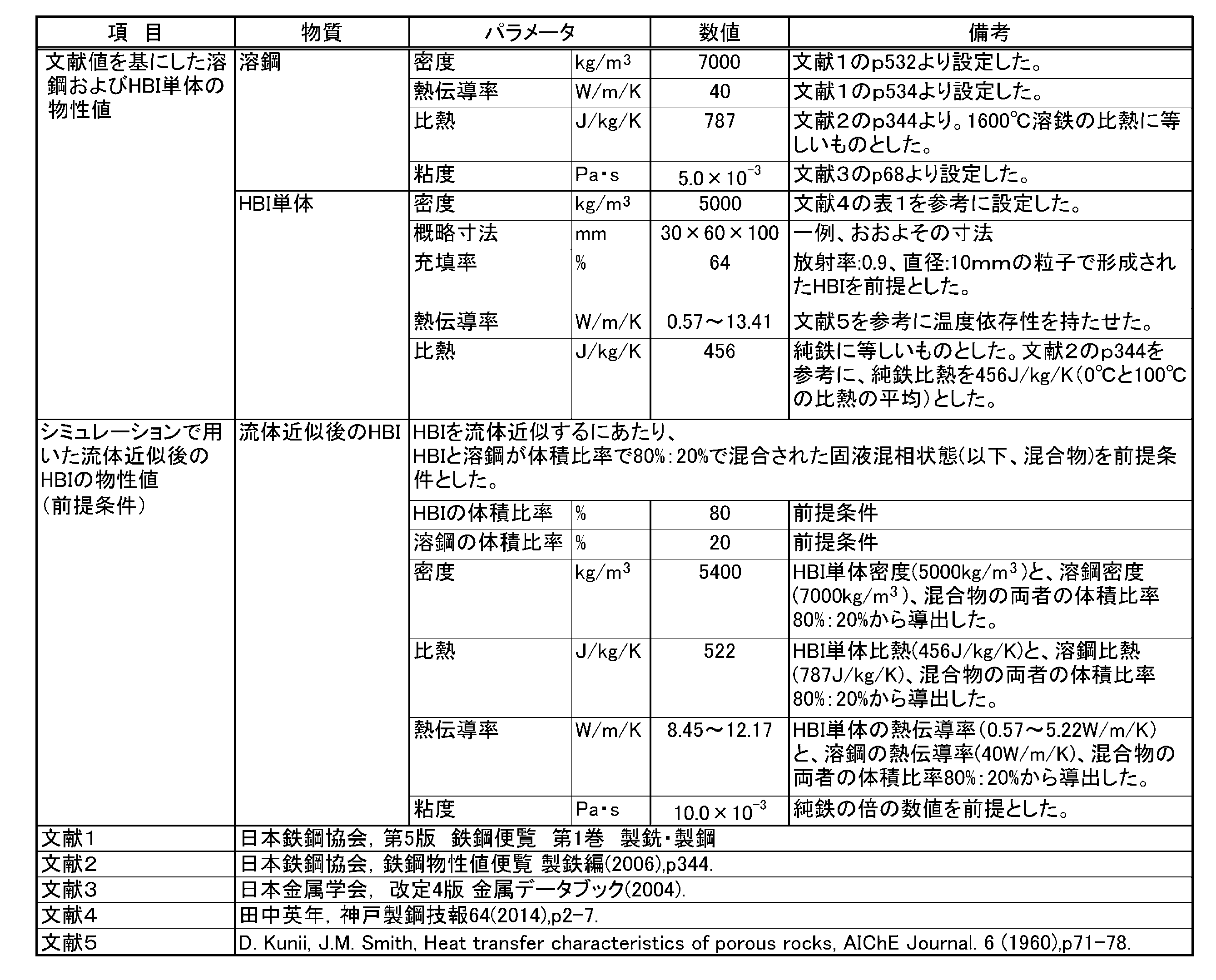
表2に示すように、HBI単体(還元鉄R)について、小さな粒子状のものを固めて塊(
インゴット)とし、その大きさは例えば(30×60×100mm)とした。これは一例であり、この大きさに限定されない。
表3に、計算条件に関する、HBI単体(還元鉄R)の温度ごとの熱伝導率(W/m/K)と、溶鋼Mの温度ごとの熱伝導率(W/m/K)、および、混合物Xの温度ごとの熱伝導率(W/m/K)について示す。
As shown in Table 2, for HBI alone (reduced iron R), small particles are solidified and turned into lumps (
The size of the toner cartridge is, for example, 30×60×100 mm. This is just an example, and the toner cartridge is not limited to this size.
Table 3 shows the thermal conductivity (W/m/K) of HBI alone (reduced iron R) at each temperature, the thermal conductivity (W/m/K) of molten steel M at each temperature, and the thermal conductivity (W/m/K) of mixture X at each temperature, for the calculation conditions.

なお、表3は100℃毎の熱伝導率を示しているが、例えば800℃超900℃未満のある温度における混合物の熱伝導率は、800℃と900℃を説明変数、10.86と11.47を非説明変数として一次近似を行い、その近似式にある温度を代入することで熱伝導率を算出した。
また、表3に示す、HBI単体の熱伝導率は、表2の文献5(D.Kunii,J.M.Smith,Heat transfer characteristics of porous rocks,AIChE Journal.6(1960),p71-78.)に基づいている。また、溶鋼Mの熱伝導率は、表2の文献1(日本鉄鋼協会,第5版 鉄鋼便覧 第1巻 製銑・製鋼)に基づいている。
It should be noted that Table 3 shows the thermal conductivity for every 100°C. For example, the thermal conductivity of the mixture at a temperature greater than 800°C and less than 900°C was calculated by performing a first-order approximation using 800°C and 900°C as explanatory variables and 10.86 and 11.47 as non-explanatory variables, and then substituting the temperature in the approximation formula.
The thermal conductivity of HBI alone shown in Table 3 is based on Reference 5 in Table 2 (D. Kunii, JM Smith, Heat transfer characteristics of porous rocks, AIChE Journal. 6 (1960), p71-78.) The thermal conductivity of molten steel M is based on Reference 1 in Table 2 (Iron and Steel Institute of Japan, 5th Edition, Steel Handbook, Vol. 1, Iron and Steelmaking).
[実施例]
以下に、本発明の電気炉1への還元鉄Rの装入方法に従って実施した実施例及び、本発明と比較するために実施した比較例について、説明する。なお、本実施例に記載した内容は本発明の例示であって、これに限定されるものではない。
本実施例における実施条件については、以下の通りである。
表4に、本実施例における実施条件(流動伝熱解析、固相(固体)の判断方法、固相率fの計算方法など)について示す。
[Example]
Examples carried out according to the method of charging reduced iron R into an electric furnace 1 of the present invention and comparative examples carried out for comparison with the present invention will be described below. Note that the contents described in the examples are merely examples of the present invention, and the present invention is not limited thereto.
The conditions for carrying out this embodiment are as follows.
Table 4 shows the implementation conditions (flow heat transfer analysis, method of determining the solid phase (solid), method of calculating the solid fraction f, etc.) in this embodiment.

表4に示すように、本実施形態では、純鉄の融点である1539℃を閾値とし、溶鋼Mの温度:1539℃以下を、固体が存在しているものとした。
また、初期の電気炉1内の溶融物について、体積:15t、温度:1600℃のものとした。この初期の溶融物(溶鋼M)がある中に、追加原料RとしてHBI(還元鉄R)を装入するものとした。
As shown in Table 4, in this embodiment, the melting point of pure iron, 1539° C., is set as the threshold value, and a temperature of molten steel M of 1539° C. or lower is considered to be a solid state.
The initial molten material in the electric furnace 1 had a volume of 15 tons and a temperature of 1600° C. HBI (reduced iron R) was charged as additional raw material R into this initial molten material (molten steel M).
HBI(還元鉄R)について、装入前温度:20℃、装入速度:0.2t/min,0.5t/min,1t/min、装入量合計:5tとした。また、投入電力について、6MW,12MWとした。
表5に、還元鉄Rの装入速度(t/min)、還元鉄Rの比装入速度s(t/min/MW)、固相率fの算出方法などについて示す。
For HBI (reduced iron R), the temperature before charging was 20°C, the charging speed was 0.2t/min, 0.5t/min, 1t/min, and the total charging amount was 5t. The input power was 6MW and 12MW.
Table 5 shows the charging rate (t/min) of the reduced iron R, the specific charging rate s (t/min/MW) of the reduced iron R, and a method for calculating the solid fraction f.

図4に、シミュレーションにおける固相率fの算出方法の概要を示す。
図4に示すように、電極6は等間隔に(平面視で略正三角形の頂点に配置されるように)3本配置している。
追加原料Rとして用いるHBI(還元鉄R)の装入位置は、3本配置された電極6に囲まれた領域の中心(電炉1の中心)付近に装入する。
FIG. 4 shows an outline of a method for calculating the solid fraction f in the simulation.
As shown in FIG. 4, three electrodes 6 are disposed at equal intervals (so as to be disposed at the vertices of a substantially equilateral triangle in a plan view).
The HBI (reduced iron R) used as the additional raw material R is charged near the center of the area surrounded by the three electrodes 6 (the center of the electric furnace 1).
なお、混合物Xは、電気炉1内において、初装原料(スクラップなど)を溶解させた溶鋼Mと、装入した還元鉄Rとが、混ざり合って存在する部分である。
還元鉄Rの比装入速度s(t/min/MW)は、還元鉄Rの装入速度(t/min)を電力(MW)で除した値である。本発明では、還元鉄Rの比装入速度sを0.07t/min/MW未満と規定した。
なお、還元鉄Rの装入速度(t/min)は、単位時間当たりの還元鉄Rの装入量を算出し平均装入速度とした値である。
The mixture X is a portion in the electric furnace 1 where the molten steel M obtained by melting the initial charge of raw materials (such as scrap) and the charged reduced iron R are mixed together.
The specific charging rate s (t/min/MW) of the reduced iron R is a value obtained by dividing the charging rate (t/min) of the reduced iron R by the electric power (MW). In the present invention, the specific charging rate s of the reduced iron R is specified to be less than 0.07 t/min/MW.
The charging speed (t/min) of the reduced iron R is an average charging speed calculated by calculating the charging amount of the reduced iron R per unit time.
固相率f(0以上1以下)=(b)÷(a)で表わされる。
(a)は、電極6のピッチサークル(PC)の中心と同じ中心で電極6の最外周を通る円Aを底面とする円柱の範囲内において、混合物Xが存在する領域の体積(m3)である。ただし、本実施形態では、円Aの直径:1346mmである。
(b)は、(a)で混合物Xの体積を求めた領域の中で、溶鋼Mの温度が1539℃以下の領域の体積(m3)である。
表6に、本発明の電気炉1への還元鉄Rの装入方法に従って実施した実施例及び、本発明と比較するために実施した比較例を示す。
Solid fraction f (0 to 1) is expressed as (b) ÷ (a).
(a) is the volume ( m3) of the region where the mixture X exists within the range of a cylinder whose base is a circle A that is the same center as the center of the pitch circle (PC) of the electrode 6 and passes through the outermost circumference of the electrode 6. In this embodiment, however, the diameter of the circle A is 1346 mm.
(b) is the volume (m 3 ) of the region where the temperature of molten steel M is 1539°C or lower, within the region in which the volume of mixture X is determined in (a).
Table 6 shows examples carried out according to the method of charging reduced iron R into the electric furnace 1 of the present invention, and comparative examples carried out for comparison with the present invention.

表6、図3などに示すように、本実施例の実験番号1は、電力が12MWの場合であって、還元鉄Rの比装入速度sが0.017t/min/MWとなり0.07t/min/MW未満を満たし、固相率fが0.663となり0.7未満を満たすこととなり、良好な結果を得た。すなわち、還元鉄Rは溶融され、溶鋼Mの流動性を確保することができるようになった。
本実施例の実験番号2は、電力が12MWの場合であって、還元鉄Rの比装入速度sが0.042t/min/MWとなり0.07t/min/MW未満を満たし、固相率fが0.691となり0.7未満を満たすこととなり、良好な結果を得た。すなわち、還元鉄Rは溶融され、溶鋼Mの流動性を確保することができるようになった。
3, etc., in experiment number 1 of this embodiment, the power was 12 MW, the specific charging rate s of the reduced iron R was 0.017 t/min/MW, which satisfied the requirement of less than 0.07 t/min/MW, and the solid fraction f was 0.663, which satisfied the requirement of less than 0.7, and thus good results were obtained. In other words, the reduced iron R was melted, and the fluidity of the molten steel M was ensured.
In the experiment No. 2 of this embodiment, the electric power was 12 MW, and the specific charging rate s of the reduced iron R was 0.042 t/min/MW, which satisfied the requirement of being less than 0.07 t/min/MW, and the solid fraction f was 0.691, which satisfied the requirement of being less than 0.7, so that good results were obtained. In other words, the reduced iron R was melted, and the fluidity of the molten steel M was ensured.
一方、比較例の実験番号3は、電力が12MWの場合であって、還元鉄Rの比装入速度sが0.083t/min/MWとなり0.07t/min/MW未満を満たさず、固相率fが0.705となり0.7未満を満たさないため、求める結果から外れることとなった。すなわち、還元鉄Rは溶融されず、溶鋼Mの流動性を確保することができない。
本実施例の実験番号4は、電力が6MWの場合であって、還元鉄Rの比装入速度sが0.033t/min/MWとなり0.07t/min/MW未満を満たし、固相率fが0.672となり0.7未満を満たすこととなり、良好な結果を得た。すなわち、還元鉄Rは溶融され、溶鋼Mの流動性を確保することができるようになった。
On the other hand, in the case of the comparative example, experiment number 3, in which the electric power was 12 MW, the specific charging rate s of the reduced iron R was 0.083 t/min/MW, which did not satisfy the requirement of being less than 0.07 t/min/MW, and the solid fraction f was 0.705, which did not satisfy the requirement of being less than 0.7, and therefore the result was outside the desired range. In other words, the reduced iron R was not melted, and the fluidity of the molten steel M could not be ensured.
In the experiment No. 4 of this embodiment, the electric power was 6 MW, and the specific charging rate s of the reduced iron R was 0.033 t/min/MW, which satisfied the requirement of less than 0.07 t/min/MW, and the solid fraction f was 0.672, which satisfied the requirement of less than 0.7, so that good results were obtained. In other words, the reduced iron R was melted, and the fluidity of the molten steel M was ensured.
一方、比較例の実験番号5、6は、電力が6MWの場合であって、還元鉄Rの比装入速度sが0.083t/min/MW,0.167t/min/MWとなり0.07t/min/MW未満を満たさず、固相率fが0.720,0.756となり0.7未満を満たさないため、求める結果から外れることとなった。すなわち、還元鉄Rは溶融されず、溶鋼Mの流動性を確保することができない。
上記の結果より、追加原料Rとして還元鉄Rを電気炉1へ装入する際には、還元鉄Rの
比装入速度sを0.07t/min/MW未満とすると、固相率fが0.7未満となり、還元鉄Rは溶融され、溶鋼Mの流動性を確保することができるようになることを知見した。
On the other hand, in the comparative examples, experiment numbers 5 and 6, the power was 6 MW, the specific charging rate s of the reduced iron R was 0.083 t/min/MW and 0.167 t/min/MW, which did not satisfy the requirement of less than 0.07 t/min/MW, and the solid fraction f was 0.720 and 0.756, which did not satisfy the requirement of less than 0.7, so that the results were outside the desired range. In other words, the reduced iron R was not melted, and the fluidity of the molten steel M could not be ensured.
From the above results, it has been found that when reduced iron R is charged into the electric furnace 1 as additional raw material R, if the specific charging rate s of the reduced iron R is less than 0.07 t/min/MW, the solid fraction f becomes less than 0.7, the reduced iron R is melted, and the fluidity of the molten steel M can be ensured.
繰り返しになるが、還元鉄Rを追加で装入したときの固相率fについて説明する。
上で詳説したように、溶鋼Mの流動性を確保するためには、固相率fを0.7未満にする必要がある。
図2に示すように、本発明では、還元鉄Rの比装入速度sを0.07t/min/MW未満とすることで、固相率fを0.7未満に維持することができる。このようにすることで、溶鋼Mの流動性を確保することができるようになるため、冷鉄源の還元鉄Rを追加で装入することによる電気炉1操業時の作業性の悪化を招くことは無い。
Again, the solid fraction f when reduced iron R is additionally charged will be described.
As explained in detail above, in order to ensure the fluidity of the molten steel M, the solid fraction f needs to be less than 0.7.
2, in the present invention, the solid fraction f can be maintained at less than 0.7 by setting the specific charging rate s of the reduced iron R to less than 0.07 t/min/MW. This ensures the fluidity of the molten steel M, and therefore does not lead to a deterioration in workability during operation of the electric furnace 1 due to additional charging of the reduced iron R as a cold iron source.
以上、本発明の電気炉1への還元鉄Rの装入(投入)方法によれば、電気炉1にて還元鉄Rを溶解するにあたって、還元鉄Rを追加で電気炉1内に装入するとき、還元鉄Rの比装入速度sを、0.07t/min/MW未満とすることで、還元鉄R装入時の溶鋼Mの流動性を確保することができるとともに、還元鉄R溶解時に溶融性に優れるようになり、電気炉1での作業時間を延ばすことなく効率よく溶解することができる。 According to the method of charging (introducing) reduced iron R into an electric furnace 1 of the present invention, when additional reduced iron R is charged into the electric furnace 1 to melt the reduced iron R in the electric furnace 1, the specific charging rate s of the reduced iron R is set to less than 0.07 t/min/MW, thereby ensuring the fluidity of the molten steel M when the reduced iron R is charged, and the reduced iron R has excellent melting properties when melted, allowing it to be melted efficiently without extending the operating time in the electric furnace 1.
なお、今回開示された実施形態はすべての点で例示であって制限的なものではないと考えられるべきである。
特に、今回開示された実施形態において、明示されていない事項、例えば、運転条件や操業条件、各種パラメータ、構成物の寸法、重量、体積などは、当業者が通常実施する範囲を逸脱するものではなく、通常の当業者であれば、容易に想定することが可能な値を採用している。
It should be noted that the embodiments disclosed herein should be considered as illustrative in all respects and not restrictive.
In particular, in the embodiments disclosed herein, matters not explicitly stated, such as operating conditions, operating conditions, various parameters, dimensions, weights, volumes of components, etc., do not deviate from the scope of ordinary practice of a person skilled in the art, and values that a person of ordinary skill in the art could easily assume are used.
1 電気炉(電炉)
2 本体
3 蓋体
4 排滓口
5 出鋼口
6 電極
M 溶鋼(溶湯)
R 還元鉄(追加原料)
X 混合物
1. Electric furnace (electric furnace)
2 Body 3 Lid 4 Slag outlet 5 Steel tapping outlet 6 Electrode M Molten steel (molten metal)
R Reduced iron (additional raw material)
X Mixture
Claims (1)
前記電気炉は、上部が開口された本体を有し、内部には電極が上方から挿入されており、
前記溶解原料は、炭素を含有する還元鉄で形成されたブリケットであり、
前記電気炉内で初装原料を予め溶解させることで形成される溶湯に、前記溶解原料を追加で装入するに際しては、
前記電気炉内への装入開始から装入終了までに装入した前記溶解原料中の前記還元鉄の総装入量である還元鉄装入量を、前記装入開始から前記装入終了までに要した時間で除することで平均装入速度を求め、求められた前記平均装入速度を投入電力で除して得られるものを、前記還元鉄の比装入速度sとした場合に、
前記還元鉄の比装入速度sが、0.07t/min/MW未満となるように、前記溶解原料を前記電気炉内に装入する
ことを特徴とする電気炉における原料溶解方法。 A method for producing molten steel using a molten raw material containing reduced iron in an arc-type electric furnace, comprising the steps of:
The electric furnace has a main body with an open top, and an electrode is inserted into the main body from above.
The melting raw material is a briquette formed of reduced iron containing carbon,
When the molten raw materials are additionally charged into the molten metal formed by previously melting the initial charge raw materials in the electric furnace,
An average charging rate is calculated by dividing a total amount of reduced iron charged in the molten raw materials from the start of charging to the end of charging into the electric furnace by a time required from the start of charging to the end of charging, and the calculated average charging rate is divided by an input power to obtain a specific charging rate s of the reduced iron.
The melting raw material is charged into the electric furnace so that the specific charging rate s of the reduced iron is less than 0.07 t/min/MW.
2. A method for melting raw materials in an electric furnace.
Priority Applications (1)
| Application Number | Priority Date | Filing Date | Title |
|---|---|---|---|
| JP2021208485A JP7588942B2 (en) | 2021-12-22 | 2021-12-22 | Method of charging reduced iron into electric furnace |
Applications Claiming Priority (1)
| Application Number | Priority Date | Filing Date | Title |
|---|---|---|---|
| JP2021208485A JP7588942B2 (en) | 2021-12-22 | 2021-12-22 | Method of charging reduced iron into electric furnace |
Publications (2)
| Publication Number | Publication Date |
|---|---|
| JP2023093079A JP2023093079A (en) | 2023-07-04 |
| JP7588942B2 true JP7588942B2 (en) | 2024-11-25 |
Family
ID=87000847
Family Applications (1)
| Application Number | Title | Priority Date | Filing Date |
|---|---|---|---|
| JP2021208485A Active JP7588942B2 (en) | 2021-12-22 | 2021-12-22 | Method of charging reduced iron into electric furnace |
Country Status (1)
| Country | Link |
|---|---|
| JP (1) | JP7588942B2 (en) |
Families Citing this family (1)
| Publication number | Priority date | Publication date | Assignee | Title |
|---|---|---|---|---|
| JP2025128503A (en) * | 2024-02-22 | 2025-09-03 | 株式会社神戸製鋼所 | Carbon oxide reduction method, steel manufacturing method, carbon oxide reduction device, and steel manufacturing device |
Citations (4)
| Publication number | Priority date | Publication date | Assignee | Title |
|---|---|---|---|---|
| JP2003105415A (en) | 2001-10-01 | 2003-04-09 | Kobe Steel Ltd | Method and device for producing molten metal |
| JP2012007225A (en) | 2010-06-28 | 2012-01-12 | Kobe Steel Ltd | Method for producing molten steel using particulate metallic iron |
| JP2018119693A (en) | 2017-01-23 | 2018-08-02 | 新日鐵住金株式会社 | Hollow electrode for electric furnace and electric furnace |
| CN108950132A (en) | 2018-09-12 | 2018-12-07 | 中冶京诚工程技术有限公司 | Electric furnace smelting device and method |
Family Cites Families (2)
| Publication number | Priority date | Publication date | Assignee | Title |
|---|---|---|---|---|
| JPS5613420A (en) * | 1979-07-12 | 1981-02-09 | Nikko Sangyo:Kk | Method and apparatus for rapid melting of direct-reduced iron |
| ATA121393A (en) * | 1993-06-21 | 1998-07-15 | Voest Alpine Ind Anlagen | CONVERTER AND METHOD FOR PRODUCING STEEL |
-
2021
- 2021-12-22 JP JP2021208485A patent/JP7588942B2/en active Active
Patent Citations (4)
| Publication number | Priority date | Publication date | Assignee | Title |
|---|---|---|---|---|
| JP2003105415A (en) | 2001-10-01 | 2003-04-09 | Kobe Steel Ltd | Method and device for producing molten metal |
| JP2012007225A (en) | 2010-06-28 | 2012-01-12 | Kobe Steel Ltd | Method for producing molten steel using particulate metallic iron |
| JP2018119693A (en) | 2017-01-23 | 2018-08-02 | 新日鐵住金株式会社 | Hollow electrode for electric furnace and electric furnace |
| CN108950132A (en) | 2018-09-12 | 2018-12-07 | 中冶京诚工程技术有限公司 | Electric furnace smelting device and method |
Also Published As
| Publication number | Publication date |
|---|---|
| JP2023093079A (en) | 2023-07-04 |
Similar Documents
| Publication | Publication Date | Title |
|---|---|---|
| JP4060034B2 (en) | Method for producing molten iron in dual furnace | |
| CN102439387B (en) | Steel production equipment | |
| JP5552754B2 (en) | Arc furnace operation method | |
| US11536514B2 (en) | Electric furnace and method for melting and reducing iron oxide-containing iron raw material | |
| JP3699123B2 (en) | Manufacturing method of iron for casting | |
| JPH0442452B2 (en) | ||
| CN1268187A (en) | Method of making iron and steel | |
| SE452476B (en) | PROCEDURE FOR MOLDING OF IRON SCRAP | |
| US20010025550A1 (en) | Process for manufacturing molten metal iron | |
| RU97118334A (en) | INSTALLATION AND METHOD FOR PRODUCING IRON MELTS | |
| JP5236926B2 (en) | Manufacturing method of molten steel | |
| JP6237664B2 (en) | Arc furnace operating method and molten steel manufacturing method | |
| JP5549198B2 (en) | Steel making method using steel scrap | |
| JP7588942B2 (en) | Method of charging reduced iron into electric furnace | |
| JP5589688B2 (en) | Hot metal production method | |
| JP3721154B2 (en) | Method for refining molten metal containing chromium | |
| JP5625654B2 (en) | Hot metal production method | |
| CN111801431A (en) | Melting plants for steel production | |
| CN117280048A (en) | Electric furnace and steel making method | |
| EP4653554A1 (en) | Molten-iron production method | |
| EP0843020B1 (en) | Double hearth electric arc furnace for continuous melting | |
| KR20140027099A (en) | Method and apparatus for making liquid iron and steel | |
| JPH11344287A (en) | Arc furnace operation method | |
| JP3629740B2 (en) | Hot metal production method | |
| JPS6036613A (en) | Production of raw molten nickel-containing stainless steel |
Legal Events
| Date | Code | Title | Description |
|---|---|---|---|
| A621 | Written request for application examination |
Free format text: JAPANESE INTERMEDIATE CODE: A621 Effective date: 20230901 |
|
| A977 | Report on retrieval |
Free format text: JAPANESE INTERMEDIATE CODE: A971007 Effective date: 20240522 |
|
| A131 | Notification of reasons for refusal |
Free format text: JAPANESE INTERMEDIATE CODE: A131 Effective date: 20240625 |
|
| A521 | Request for written amendment filed |
Free format text: JAPANESE INTERMEDIATE CODE: A523 Effective date: 20240821 |
|
| TRDD | Decision of grant or rejection written | ||
| A01 | Written decision to grant a patent or to grant a registration (utility model) |
Free format text: JAPANESE INTERMEDIATE CODE: A01 Effective date: 20241112 |
|
| A61 | First payment of annual fees (during grant procedure) |
Free format text: JAPANESE INTERMEDIATE CODE: A61 Effective date: 20241112 |
|
| R150 | Certificate of patent or registration of utility model |
Ref document number: 7588942 Country of ref document: JP Free format text: JAPANESE INTERMEDIATE CODE: R150 |