JP7588932B2 - Motor Control Method - Google Patents
Motor Control Method Download PDFInfo
- Publication number
- JP7588932B2 JP7588932B2 JP2020152099A JP2020152099A JP7588932B2 JP 7588932 B2 JP7588932 B2 JP 7588932B2 JP 2020152099 A JP2020152099 A JP 2020152099A JP 2020152099 A JP2020152099 A JP 2020152099A JP 7588932 B2 JP7588932 B2 JP 7588932B2
- Authority
- JP
- Japan
- Prior art keywords
- motor
- torque
- driver
- rotation speed
- command torque
- Prior art date
- Legal status (The legal status is an assumption and is not a legal conclusion. Google has not performed a legal analysis and makes no representation as to the accuracy of the status listed.)
- Active
Links
- 238000000034 method Methods 0.000 title claims description 22
- 230000035939 shock Effects 0.000 claims description 44
- 230000008859 change Effects 0.000 claims description 18
- 101150070189 CIN3 gene Proteins 0.000 description 13
- 238000010586 diagram Methods 0.000 description 11
- 238000004891 communication Methods 0.000 description 10
- 230000004043 responsiveness Effects 0.000 description 10
- 230000004044 response Effects 0.000 description 9
- 230000001629 suppression Effects 0.000 description 9
- 230000008569 process Effects 0.000 description 6
- 230000001133 acceleration Effects 0.000 description 4
- 238000009499 grossing Methods 0.000 description 4
- 230000003111 delayed effect Effects 0.000 description 3
- 230000000694 effects Effects 0.000 description 3
- 230000005540 biological transmission Effects 0.000 description 2
- 230000004048 modification Effects 0.000 description 2
- 238000012986 modification Methods 0.000 description 2
- 238000012545 processing Methods 0.000 description 2
- 230000036962 time dependent Effects 0.000 description 2
- 230000009471 action Effects 0.000 description 1
- 230000007423 decrease Effects 0.000 description 1
- 230000003247 decreasing effect Effects 0.000 description 1
- 238000013461 design Methods 0.000 description 1
- 230000001360 synchronised effect Effects 0.000 description 1
Images


Classifications
-
- Y—GENERAL TAGGING OF NEW TECHNOLOGICAL DEVELOPMENTS; GENERAL TAGGING OF CROSS-SECTIONAL TECHNOLOGIES SPANNING OVER SEVERAL SECTIONS OF THE IPC; TECHNICAL SUBJECTS COVERED BY FORMER USPC CROSS-REFERENCE ART COLLECTIONS [XRACs] AND DIGESTS
- Y02—TECHNOLOGIES OR APPLICATIONS FOR MITIGATION OR ADAPTATION AGAINST CLIMATE CHANGE
- Y02T—CLIMATE CHANGE MITIGATION TECHNOLOGIES RELATED TO TRANSPORTATION
- Y02T10/00—Road transport of goods or passengers
- Y02T10/60—Other road transportation technologies with climate change mitigation effect
- Y02T10/64—Electric machine technologies in electromobility
-
- Y—GENERAL TAGGING OF NEW TECHNOLOGICAL DEVELOPMENTS; GENERAL TAGGING OF CROSS-SECTIONAL TECHNOLOGIES SPANNING OVER SEVERAL SECTIONS OF THE IPC; TECHNICAL SUBJECTS COVERED BY FORMER USPC CROSS-REFERENCE ART COLLECTIONS [XRACs] AND DIGESTS
- Y02—TECHNOLOGIES OR APPLICATIONS FOR MITIGATION OR ADAPTATION AGAINST CLIMATE CHANGE
- Y02T—CLIMATE CHANGE MITIGATION TECHNOLOGIES RELATED TO TRANSPORTATION
- Y02T10/00—Road transport of goods or passengers
- Y02T10/60—Other road transportation technologies with climate change mitigation effect
- Y02T10/72—Electric energy management in electromobility
Landscapes
- Electric Propulsion And Braking For Vehicles (AREA)
Description
本発明は、車両の走行用の動力を発生するモータの制御方法に関する。 The present invention relates to a method for controlling a motor that generates power for driving a vehicle.
電気自動車(EV:Electric Vehicle)などの電動車両には、走行用の駆動源としてのモータを制御するため、EV-ECU(Electronic Control Unit:電子制御ユニット)およびINV(Inverter:インバータ)を搭載したものがある。INVには、昇圧回路およびインバータ回路を含む高電圧回路が設けられている。モータには、高電圧回路から出力される交流電力が供給される。また、EV-ECUおよびINVは、それぞれマイコン(マイクロコントローラ)を備えている。EV-ECUとINVとは、CAN(Controller Area Network)通信プロトコルによる通信が可能に接続されている。 Some electric vehicles, such as electric vehicles (EVs), are equipped with an EV-ECU (Electronic Control Unit) and an INV (Inverter) to control the motor that serves as the driving source for driving. The INV is equipped with a high-voltage circuit that includes a boost circuit and an inverter circuit. The motor is supplied with AC power output from the high-voltage circuit. The EV-ECU and INV each include a microcontroller. The EV-ECU and INV are connected so that they can communicate using the CAN (Controller Area Network) communication protocol.
図5は、モータトルク制御の流れを示す図である。図6は、アクセル開度、ドライバ要求トルク、指示トルクおよび実行トルクの時間変化の一例を示す図である。 Figure 5 shows the flow of motor torque control. Figure 6 shows an example of the change over time in the accelerator opening, driver requested torque, command torque, and actual torque.
EV-ECUおよびINVでは、マイコンにより、モータトルク制御のための処理が実行される。 In the EV-ECU and INV, the microcomputer executes processing for motor torque control.
すなわち、EV-ECUでは、ドライバ情報が読み込まれる(ステップS81)。ドライバ情報は、ドライバによるアクセル操作やブレーキ操作などのドライバ操作の情報である。INVでは、モータ状態パラメータが計測される(ステップS91)。モータ状態パラメータは、モータ回転数およびモータトルクなど、モータの状態を表すパラメータである。INVで計測されたモータ状態パラメータは、INVからEV-ECUに送信される。そして、EV-ECUでは、ドライバ情報およびモータ状態パラメータから、ドライバの要求に応じたドライバ要求トルクが算出され(ステップS82)、そのドライバ要求トルクに基づいて、指示トルクが設定される。指示トルクは、EV-ECUからINVに送信され、INVでは、高電圧回路から指示トルクに応じた交流電力が出力されるように、高電圧回路の動作が制御される(ステップS92:モータ制御実行)。 That is, the EV-ECU reads the driver information (step S81). The driver information is information on the driver's operations such as the accelerator operation and the brake operation by the driver. The INV measures the motor state parameters (step S91). The motor state parameters are parameters that indicate the state of the motor, such as the motor rotation speed and the motor torque. The motor state parameters measured by the INV are transmitted from the INV to the EV-ECU. The EV-ECU then calculates the driver request torque according to the driver's request from the driver information and the motor state parameters (step S82), and sets the command torque based on the driver request torque. The command torque is transmitted from the EV-ECU to the INV, and the INV controls the operation of the high-voltage circuit so that AC power according to the command torque is output from the high-voltage circuit (step S92: execute motor control).
ドライバ要求トルクがモータトルクの目標とされて、その目標とモータ状態パラメータに含まれるモータトルクとの偏差が大きい場合は、モータから出力されるモータトルク(実行トルク)が急峻に立ち上がり、電動車両の駆動系(ドライブシャフト)のねじれによるショックが発生する。そのため、EV-ECUでは、図6に示されるように、ドライバ要求トルクに対して指示トルクの立ち上がりを緩やかにするトルクなまし処理が行われる(ステップS83)。そして、トルクなまし処理により設定された指示トルクがEV-ECUからINVに送信される。 When the driver requested torque is set as the target for the motor torque and there is a large deviation between the target and the motor torque included in the motor state parameters, the motor torque (actual torque) output from the motor rises sharply, causing a shock due to twisting of the drive system (drive shaft) of the electric vehicle. For this reason, the EV-ECU performs a torque smoothing process (step S83) to smooth the rise of the command torque relative to the driver requested torque, as shown in FIG. 6. The command torque set by the torque smoothing process is then transmitted from the EV-ECU to the INV.
ところが、INVとEV-ECUとの間でモータ状態パラメータおよび指示トルクの通信が行われるため、ドライバ操作に対して実行トルクの立ち上がりが遅れる。これがトルクなまし処理と相まって、ドライバ操作に対するモータトルクの応答性が悪化する。しかも、モータ情報パラメータがINVからEV-ECUに送信されるため、同時刻におけるドライバ情報とモータ情報パラメータとを制御に用いることが困難であり、モータのフィードバック制御の精度が低い。そのため、トルクなまし処理を行っても、駆動系のねじれによるショックの発生の抑制が困難である。 However, because communication of motor state parameters and command torque takes place between the INV and EV-ECU, the rise of the effective torque is delayed in response to driver operation. This, combined with the torque smoothing process, deteriorates the responsiveness of the motor torque to driver operation. Furthermore, because the motor information parameters are sent from the INV to the EV-ECU, it is difficult to use driver information and motor information parameters at the same time for control, and the accuracy of the motor feedback control is low. Therefore, even if torque smoothing is performed, it is difficult to suppress the occurrence of shocks caused by torsion in the drive system.
本発明の目的は、ドライバ操作に対するモータトルクの応答性の確保と、駆動系のねじれによるショックの発生の抑制とを両立できる、モータ制御方法を提供することである。 The object of the present invention is to provide a motor control method that can ensure the responsiveness of the motor torque to the driver's operation while suppressing the occurrence of shocks due to torsion in the drive system.
前記の目的を達成するため、本発明の一の局面に係るモータ制御方法は、走行用の動力を発生するモータと、指示トルクを設定する制御ユニットと、制御ユニットと双方向に通信可能に接続され、指示トルクに応じた回路動作により交流電力をモータに供給するインバータ回路を備えるインバータとを搭載した車両におけるモータ制御方法であって、インバータは、モータの状態を計測して、モータの状態を表すモータ状態パラメータを制御ユニットに送信し、制御ユニットは、ドライバによる車両の加減速のためのドライバ操作の情報を取得して、当該ドライバ操作の情報およびインバータから受信したモータ状態パラメータから、ドライバの要求に応じたドライバ要求トルクを求め、ドライバ要求トルクをモータが発生するモータトルクの目標として、その目標に応じた指示トルクを設定し、その設定した指示トルクが予め定めたショック発生トルク値を超えた場合、所定時間、指示トルクを低減する。 In order to achieve the above object, a motor control method according to one aspect of the present invention is a motor control method for a vehicle equipped with a motor that generates power for driving, a control unit that sets a command torque, and an inverter that is connected to the control unit so as to be able to communicate bidirectionally and has an inverter circuit that supplies AC power to the motor by circuit operation according to the command torque, in which the inverter measures the state of the motor and transmits motor state parameters representing the state of the motor to the control unit, the control unit acquires information on the driver's operation for accelerating or decelerating the vehicle by the driver, determines a driver request torque according to the driver's request from the information on the driver's operation and the motor state parameters received from the inverter, sets a command torque according to the target, with the driver request torque as a target for the motor torque generated by the motor, and reduces the command torque for a predetermined time if the set command torque exceeds a predetermined shock generating torque value.
この方法によれば、制御ユニットでは、自ら取得したドライバ操作の情報と、インバータから受信したモータ状態パラメータとから、ドライバ操作によるドライバの要求に応じたドライバ要求トルクが求められる。そして、ドライバ要求トルクがモータトルクの目標とされて、その目標に応じた指示トルクが設定される。インバータでは、指示トルクに応じた交流電力がモータに供給されるように、インバータの回路動作が制御される。そのため、ドライバ操作に対してモータから出力されるモータトルク(実行トルク)が急峻に立ち上がる。その結果、ドライバ操作に対して良好な応答性で車両が加速する。 According to this method, the control unit obtains a driver request torque according to the driver's request based on the driver's operation information acquired by the control unit and the motor state parameters received from the inverter. The driver request torque is then set as a target for the motor torque, and a command torque according to the target is set. The inverter controls the inverter circuit operation so that AC power according to the command torque is supplied to the motor. Therefore, the motor torque (actual torque) output from the motor in response to the driver's operation rises sharply. As a result, the vehicle accelerates with good responsiveness to the driver's operation.
しかし、モータトルクが所定以上の値まで急峻に立ち上がると、車両の駆動系に大きなねじれが生じ、そのねじれが解消されるときにショックが発生する。 However, if the motor torque rises sharply above a certain value, a large twist occurs in the vehicle's drivetrain, and a shock occurs when the twist is released.
そこで、指示トルクが予め定められたショック発生トルク値を超えた場合、その後の所定時間、指示トルクが低減される。これにより、駆動系のねじれが解消される方向にモータトルクが働くので、駆動系に大きなねじれが生じることを抑制でき、ねじれが解消されるときのショックの発生を抑制することができる。 Therefore, when the command torque exceeds a predetermined shock generating torque value, the command torque is reduced for a predetermined period of time thereafter. This causes the motor torque to act in a direction that eliminates the torsion in the drive system, preventing a large torsion from occurring in the drive system and preventing the occurrence of a shock when the torsion is eliminated.
よって、ドライバ操作に対するモータトルクの応答性の確保と、駆動系のねじれによるショックの発生の抑制とを両立させることができる。 This makes it possible to ensure the responsiveness of the motor torque to the driver's operation while also suppressing the occurrence of shocks caused by twisting of the drive system.
本発明の他の局面に係るモータ制御方法は、走行用の動力を発生するモータと、指示トルクを設定する制御ユニットと、制御ユニットと双方向に通信可能に接続され、指示トルクに応じた回路動作により交流電力をモータに供給するインバータ回路を備えるインバータとを搭載した車両におけるモータ制御方法であって、インバータは、モータの状態を計測して、モータの状態を表すモータ状態パラメータを制御ユニットに送信し、制御ユニットは、ドライバによる車両の加減速のためのドライバ操作の情報を取得して、当該ドライバ操作の情報およびインバータから受信したモータ状態パラメータから、ドライバの要求に応じたドライバ要求トルクを求め、ドライバ要求トルクをモータが発生するモータトルクの目標として、その目標に応じた指示トルクを設定し、モータトルクが目標に到達する時点を含む所定時間では、現在のモータ回転数とドライブシャフト回転数をモータ回転数に換算した回転数(又はそれに類するもの)との偏差に応じた指示トルクを設定する。 A motor control method according to another aspect of the present invention is a motor control method for a vehicle equipped with a motor that generates power for driving, a control unit that sets a command torque, and an inverter that is connected to the control unit so as to be able to communicate bidirectionally and has an inverter circuit that supplies AC power to the motor by circuit operation according to the command torque, in which the inverter measures the state of the motor and transmits motor state parameters representing the state of the motor to the control unit, the control unit acquires information on the driver's operation for accelerating or decelerating the vehicle by the driver, determines a driver request torque according to the driver's request from the information on the driver's operation and the motor state parameters received from the inverter, sets a command torque according to the target for the motor torque generated by the motor as the driver request torque, and sets a command torque according to the target at a predetermined time including the time when the motor torque reaches the target, and sets a command torque according to the deviation between the current motor rotation speed and the rotation speed (or a similar value) obtained by converting the drive shaft rotation speed into the motor rotation speed.
この方法によれば、制御ユニットでは、自ら取得したドライバ操作の情報と、インバータから受信したモータ状態パラメータとから、ドライバ操作によるドライバの要求に応じたドライバ要求トルクが求められる。そして、ドライバ要求トルクがモータトルクの目標とされて、その目標に応じた指示トルクが設定される。インバータでは、指示トルクに応じた交流電力がモータに供給されるように、インバータの回路動作が制御される。そのため、ドライバ操作に対してモータから出力されるモータトルク(実行トルク)が急峻に立ち上がる。その結果、ドライバ操作に対して良好な応答性で車両が加速する。 According to this method, the control unit obtains a driver request torque according to the driver's request based on the driver's operation information acquired by the control unit and the motor state parameters received from the inverter. The driver request torque is then set as a target for the motor torque, and a command torque according to the target is set. The inverter controls the inverter circuit operation so that AC power according to the command torque is supplied to the motor. Therefore, the motor torque (actual torque) output from the motor in response to the driver's operation rises sharply. As a result, the vehicle accelerates with good responsiveness to the driver's operation.
かかる制御は、フィードフォワード制御であり、フィードフォワード制御では、外乱による駆動系ねじれを考慮したトルク制御が困難である。一方、フィードバック制御を常に行った場合、モータトルクにハンチングが発生し、車両の加速の滑らかさが損なわれる。また、モータ状態パラメータがインバータから制御ユニットに送信される構成では、同時刻におけるドライバ情報とモータ情報パラメータとを制御に用いることが困難であるため、フィードバック制御の精度が低くなる。その結果、車両の駆動系のねじれによるショックの発生を抑制する処理が行われても、そのショックの発生を抑制できないおそれがある。 This type of control is feedforward control, and with feedforward control, it is difficult to control the torque while taking into account the torsion of the drive system due to external disturbances. On the other hand, if feedback control is always performed, hunting occurs in the motor torque, impairing the smoothness of vehicle acceleration. Also, in a configuration in which motor state parameters are transmitted from the inverter to the control unit, it is difficult to use driver information and motor information parameters at the same time for control, and the accuracy of the feedback control is low. As a result, even if a process is performed to suppress the occurrence of shock due to torsion of the vehicle's drive system, the occurrence of the shock may not be suppressed.
そこで、モータトルクが目標に到達する時点を含む所定時間に限り、現在のモータ回転数とドライブシャフト回転数をモータ回転数に換算した回転数(又はそれに類するもの)との偏差に応じた指示トルクが設定されて、モータトルクのフィードバック制御が行われる。これにより、モータトルクのハンチングを抑制しつつ、モータトルクを目標に到達させることができる。しかも、精度の低いフィードバック制御が常には行われないので、駆動系のねじれによるショックの発生を抑制する処理が行われる場合に、ショックの発生を良好に抑制することができる。 Therefore, only for a predetermined time including the time when the motor torque reaches the target, a command torque is set according to the deviation between the current motor rotation speed and the rotation speed (or a similar value) obtained by converting the drive shaft rotation speed into the motor rotation speed, and feedback control of the motor torque is performed. This makes it possible to make the motor torque reach the target while suppressing hunting of the motor torque. Moreover, since low-precision feedback control is not always performed, when processing is performed to suppress the occurrence of shock due to torsion in the drive system, the occurrence of shock can be suppressed effectively.
よって、ドライバ操作に対するモータトルクの応答性の確保と、駆動系のねじれによるショックの発生の抑制とを両立させることができる。 This makes it possible to ensure the responsiveness of the motor torque to the driver's operation while also suppressing the occurrence of shocks caused by twisting of the drive system.
制御ユニットからインバータに指示トルクが送信されるので、その通信時間分、指示トルクの出力に対してインバータの応答が遅れる。そのため、モータトルクの目標と実際のモータトルクとの偏差に応じた指示トルクは、指示トルクの出力に対するインバータの応答の遅れを考慮して、モータトルクの時間変化がモータ回転数の時間変化と逆位相となるように設定されることが好ましい。 Since the command torque is transmitted from the control unit to the inverter, the inverter's response to the command torque output is delayed by the communication time. Therefore, it is preferable that the command torque corresponding to the deviation between the target motor torque and the actual motor torque is set so that the time change of the motor torque is in the opposite phase to the time change of the motor rotation speed, taking into account the delay in the inverter's response to the command torque output.
モータ回転数の時間変化とモータトルクの時間変化とが逆位相になるので、駆動系のねじれを小さくでき、そのねじれによるショックの発生を一層抑制することができる。 Because the time change in motor rotation speed and the time change in motor torque are in opposite phase, torsion in the drive system can be reduced, further suppressing the occurrence of shocks caused by torsion.
なお、本発明は、モータ制御方法の形態で実現できるだけでなく、たとえば、モータを制御するシステムの形態で実現することもできる。 The present invention can be realized not only in the form of a motor control method, but also in the form of a system for controlling a motor, for example.
すなわち、本発明は、走行用の動力を発生するモータを搭載した車両に用いられて、モータを制御するシステムであって、指示トルクを設定する制御ユニットと、制御ユニットと双方向に通信可能に接続され、指示トルクに応じた回路動作により交流電力をモータに供給するインバータ回路を備えるインバータとを含み、インバータは、モータの状態を計測して、モータの状態を表すモータ状態パラメータを制御ユニットに送信し、制御ユニットは、ドライバによる車両の加減速のためのドライバ操作の情報を取得して、当該ドライバ操作の情報およびインバータから受信したモータ状態パラメータから、ドライバの要求に応じたドライバ要求トルクを求め、ドライバ要求トルクをモータが発生するモータトルクの目標として、その目標に応じた指示トルクを設定し、その設定した指示トルクが予め定めたショック発生トルク値を超えた場合、所定時間、指示トルクを低減する、モータ制御システムとして実現することができる。 In other words, the present invention is a system for use in a vehicle equipped with a motor that generates power for driving, and controls the motor, including a control unit that sets a command torque, and an inverter that is connected to the control unit so as to be able to communicate bidirectionally and has an inverter circuit that supplies AC power to the motor by circuit operation according to the command torque, the inverter measures the state of the motor and transmits motor state parameters representing the state of the motor to the control unit, the control unit acquires information about the driver's operation for accelerating or decelerating the vehicle by the driver, determines a driver request torque according to the driver's request from the information about the driver's operation and the motor state parameters received from the inverter, sets a command torque according to the target for the motor torque generated by the motor as the driver request torque, and can be realized as a motor control system that reduces the command torque for a predetermined period of time if the set command torque exceeds a predetermined shock generating torque value.
この構成によれば、前述した本発明の一の局面に係るモータ制御方法と同様の作用効果を奏することができる。 This configuration can achieve the same effects as the motor control method according to one aspect of the present invention described above.
また、本発明は、走行用の動力を発生するモータを搭載した車両に用いられて、モータを制御するシステムであって、指示トルクを設定する制御ユニットと、制御ユニットと双方向に通信可能に接続され、指示トルクに応じた回路動作により交流電力をモータに供給するインバータ回路を備えるインバータとを含み、インバータは、モータの状態を計測して、モータの状態を表すモータ状態パラメータを制御ユニットに送信し、制御ユニットは、ドライバによる車両の加減速のためのドライバ操作の情報を取得して、当該ドライバ操作の情報およびインバータから受信したモータ状態パラメータから、ドライバの要求に応じたドライバ要求トルクを求め、ドライバ要求トルクをモータが発生するモータトルクの目標として、その目標に応じた指示トルクを設定し、モータトルクが目標に到達する時点を含む所定時間では、現在のモータ回転数とドライブシャフト回転数をモータ回転数に換算した回転数(又はそれに類するもの)との偏差に応じた指示トルクを設定する、モータ制御システムとして実現することもできる。 The present invention can also be realized as a motor control system that is used in a vehicle equipped with a motor that generates power for driving, and that controls the motor, and includes a control unit that sets a command torque, and an inverter that is connected to the control unit so as to be able to communicate bidirectionally and has an inverter circuit that supplies AC power to the motor by circuit operation according to the command torque, the inverter measures the state of the motor and transmits motor state parameters that represent the state of the motor to the control unit, the control unit acquires information about the driver's operation for accelerating or decelerating the vehicle by the driver, determines a driver request torque according to the driver's request from the information about the driver's operation and the motor state parameters received from the inverter, sets a command torque according to the target for the motor torque generated by the motor using the driver request torque as a target, and sets a command torque according to the target at a predetermined time including the time when the motor torque reaches the target, and sets a command torque according to the deviation between the current motor rotation speed and the rotation speed (or a similar value) obtained by converting the drive shaft rotation speed into the motor rotation speed.
この構成によれば、前述した本発明の他の局面に係るモータ制御方法と同様の作用効果を奏することができる。 This configuration can achieve the same effects as the motor control methods according to the other aspects of the present invention described above.
本発明によれば、ドライバ操作に対するモータトルクの応答性の確保と、駆動系のねじれによるショックの発生の抑制とを両立することができる。 The present invention makes it possible to ensure the responsiveness of the motor torque to the driver's operation while suppressing the occurrence of shocks due to torsion in the drive system.
以下では、本発明の実施の形態について、添付図面を参照しつつ詳細に説明する。 The following describes in detail an embodiment of the present invention with reference to the attached drawings.
<制御システム>
図1は、本発明の一実施形態に係るモータ制御方法が実施される制御システム1の構成を示すブロック図である。
<Control System>
FIG. 1 is a block diagram showing the configuration of a
制御システム1は、たとえば、駆動モータ2を走行用の駆動源として搭載した電気自動車(EV:Electric Vehicle)に搭載される。駆動モータ2は、たとえば、回転子に永久磁石を用いた永久磁石同期モータ(PMSM:Permanent Magnet Synchronous Motor)である。
The
制御システム1には、EV-ECU(Electronic Control Unit:電子制御ユニット)3およびINV(Inverter:インバータ)4が含まれる。
The
EV-ECU3は、マイコン(マイクロコントローラ)11を備えている。マイコン11には、CPU、フラッシュメモリなどの不揮発性メモリおよびDRAM(Dynamic Random Access Memory)などの揮発性メモリが内蔵されている。また、EV-ECU3は、INV4や電気自動車に搭載される他のECUとの間でのCAN(Controller Area Network)通信プロトコルによる双方向のデータ通信(以下、単に「CAN通信」という。)を可能にするため、CANトランシーバ12を備えている。
The EV-
INV4は、マイコン21を備えている。マイコン21には、マイコン11と同様、CPU、フラッシュメモリなどの不揮発性メモリおよびDRAMなどの揮発性メモリが内蔵されている。また、INV4は、EV-ECU3との間でのCAN通信プロトコルによる双方向のデータ通信を可能にするため、CANトランシーバ22を備えている。
INV4 is equipped with a
INV4は、駆動モータ2に駆動電流を供給する高電圧回路23を備えている。高電圧回路23は、直流電力を昇圧する昇圧コンバータ回路(図示せず)と、昇圧コンバータによる昇圧後の直流電力を交流電力に変換するインバータ回路24とを含む。電気自動車には、複数の二次電池を組み合わせた組電池からなるバッテリ(図示せず)が搭載されており、プラス配線25は、バッテリの正極端子に接続され、マイナス配線26は、バッテリの負極端子に接続されている。
INV4 is equipped with a high-
INV4では、マイコン21により、ゲートドライブ回路(図示せず)によりインバータ回路24が制御される。駆動モータ2には、インバータ回路24により変換された交流電力が供給される。
In INV4, the
<モータトルク制御>
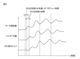
図2Aおよび図2Bは、モータトルク制御の流れを示す図である。図3は、アクセル開度、ドライバ要求トルクおよび指示トルクの時間変化の一例を示す図である。図4は、モータ回転数、F/Bトルクおよび実行トルクの時間変化の一例を示す図である。
<Motor torque control>
Fig. 2A and Fig. 2B are diagrams showing the flow of motor torque control. Fig. 3 is a diagram showing an example of time-dependent changes in accelerator opening, driver requested torque, and command torque. Fig. 4 is a diagram showing an example of time-dependent changes in motor rotation speed, F/B torque, and effective torque.
EV-ECU3のマイコン11およびINV4のマイコン21は、駆動モータ2が発生するモータトルクを制御するため、次に述べる処理を実行する。
The
EV-ECU3では、ドライバ操作の情報であるドライバ情報が読み込まれる(ステップS1)。ドライバ操作は、電気自動車の加減速のためのドライバによる操作である。ドライバ操作には、アクセル操作(たとえば、アクセルペダルの操作)やブレーキ操作(たとえば、ブレーキペダルの操作)が含まれ、ドライバ操作の情報には、アクセル操作によるアクセル開度の情報およびブレーキ操作によるブレーキのオン/オフの情報が含まれる。
The EV-
一方、INV4では、駆動モータ2の状態を表すモータ状態パラメータが計測される(ステップS21)。モータ状態パラメータには、駆動モータ2の回転数であるモータ回転数および駆動モータ2が発生するモータトルクが含まれる。INV4で計測されたモータ状態パラメータは、CAN通信により、INV4からEV-ECU3に送信される。
Meanwhile, in INV4, motor state parameters that represent the state of the
モータ状態パラメータを受信したEV-ECU3では、その受信したモータ状態パラメータと、自ら取得したドライバ情報とから、ドライバが要求する加速が得られるモータトルクであるドライバ要求トルクが算出される(ステップS2)。ドライバが要求する加速の度合いは、ドライバ操作に現れる。すなわち、ドライバが要求する加速の度合いが大きいほど、アクセル操作によるアクセル開度が大きくなる。EV-ECU3では、現在の駆動モータ2のモータ回転数およびモータトルクならびにアクセル開度などからドライバ要求トルクが算出される。
The EV-
つづいて、EV-ECU3では、ドライバ要求トルクをモータトルクの目標として、その目標に応じた指示トルクを設定した場合に、指示トルクがショック発生トルク値を超えるか否かが判断される(ステップS3)。ショック発生トルク値は、たとえば、それ以上のモータトルクが駆動モータ2から出力されると電気自動車の駆動系にねじれによるショックが発生する限界値であり、予め計算により求められている。
Next, the EV-
指示トルクがショック発生トルク値を超えない場合(ステップS3のNO)、モータトルクが目標に到達する時点を含む所定時間内であるか否かが判断される。具体的には、次の判断ステップS6~S11のすべてが肯定される場合、モータトルクが目標に到達する時点を含む所定時間内であると判断され、次の判断ステップS6~S11のいずれか1つが少なくとも否定される場合、所定時間内ではないと判断される。 If the command torque does not exceed the shock generating torque value (NO in step S3), it is determined whether or not it is within a predetermined time including the time when the motor torque reaches the target. Specifically, if all of the following decision steps S6 to S11 are positive, it is determined that it is within the predetermined time including the time when the motor torque reaches the target, and if at least one of the following decision steps S6 to S11 is negative, it is determined that it is not within the predetermined time.
S6:アクセル開度が第1値以上増加してから第1時間内である。
S7:ブレーキオフから第2時間内である。
S8:アクセル開度の変化が第2値以下である。
S9:アクセル開度が減少していない。
S10:ブレーキオフである。
S11:指示トルクが第3値以上である。
S6: The first time period has elapsed since the accelerator opening degree increased by the first value or more.
S7: Within the second time period from brake-off.
S8: The change in the accelerator opening is equal to or smaller than a second value.
S9: The accelerator opening is not decreased.
S10: The brake is off.
S11: The command torque is equal to or greater than a third value.
ここで、第1値は、駆動系ねじれでショックが発生するトルク指示値を出力するアクセル開度である。第1時間は、指示トルクがドライバ要求トルクに到達するまでの予想時間である。第2時間は、ブレーキオフ後にドライバがアクセルを踏んでから指示トルクがドライバ要求トルクに到達するまでの予想時間である。第2値は、アクセル開度に応じて算出されるトルクの増加分で駆動系ねじれによるショックが発生するアクセル開度変化量である。第3値は、指示トルクが目標トルクに到達する際に発生する駆動系ショックをF/B制御で取り切れる最大のトルク値である。 Here, the first value is the accelerator opening that outputs a torque command value that generates a shock due to driveline torsion. The first time is the predicted time until the command torque reaches the driver requested torque. The second time is the predicted time until the command torque reaches the driver requested torque after the driver steps on the accelerator after the brake is released. The second value is the amount of change in accelerator opening that is the increase in torque calculated according to the accelerator opening and generates a shock due to driveline torsion. The third value is the maximum torque value that can be completely removed by F/B control from the driveline shock that occurs when the command torque reaches the target torque.
モータトルクが目標に到達する時点を含む所定時間内でない場合(図2BのステップS6~S11のいずれかでNO)、EV-ECU3では、ドライバ要求トルクがモータトルクの目標とされて、その目標に応じた指示トルクが設定される(ステップS13)。指示トルクは、EV-ECU3からINV4に送信される。
If it is not within the predetermined time including the time when the motor torque reaches the target (NO in any of steps S6 to S11 in FIG. 2B), the EV-
INV4では、EV-ECU3から指示トルクを受信すると、高電圧回路23から指示トルクに応じた交流電力が出力されるように、高電圧回路23(インバータ回路24)の動作が制御される(ステップS22:モータ制御実行)。
When INV4 receives a command torque from the EV-
一方、指示トルクがショック発生トルク値を超える場合(ステップS3のYES)、EV-ECU3では、駆動系のねじれによるショックの発生を抑制するためのショック抑制制御が行われているか否かが判断される(ステップS4)。指示トルクがショック発生トルク値を超えると判断された場合、その判断からの所定時間、EV-ECU3では、ショック抑制制御が行われる。ショック抑制制御では、ショック抑制トルクが算出されて(ステップS5)、その算出されたショック抑制トルクが指示トルクから減算される。ショック抑制トルクは、たとえば、図3に示されるように、時刻T1で指示トルクがショック発生トルク値を超えると判断された場合、時刻T1から時刻T2までの所定時間において、指示トルクが時間経過に伴って減少した後に増加するように設定される。実施例としてSin波形を模擬した波形を使用する際は、その周波数および振幅は、マップまたは演算により、駆動モータ2のモータ回転数に応じて設定される。
On the other hand, when the command torque exceeds the shock generating torque value (YES in step S3), the EV-
ドライバ要求トルクに応じた指示トルクが設定されて(ステップS13)、その指示トルクによるモータトルクの制御が進むうちに、モータトルクが目標に到達する時点を含む所定時間内になると(ステップS11のYES、時刻T3)、EV-ECU3では、現在のモータ回転数とドライブシャフト回転数をモータ回転数に換算した回転数(又はそれに類するもの)との偏差に係数をかけたトルクがF/Bトルクとして算出される(ステップS12)。そして、EV-ECU3では、F/Bトルクに応じた指示トルクが設定され(ステップS13)、その指示トルクがINV4に送信される。INV4では、EV-ECU3から指示トルクを受信すると、高電圧回路23から指示トルクに応じた交流電力が出力されるように、高電圧回路23の動作が制御される(ステップS22)。すなわち、時刻T3から時刻T4までの所定時間において、駆動モータ2のモータトルクがフィードバック制御され、このフィードバック制御により、モータトルクが目標に収束する。
The command torque corresponding to the driver request torque is set (step S13), and as the control of the motor torque by the command torque progresses, when the motor torque reaches the target within a predetermined time (YES in step S11, time T3), the EV-
このとき、EV-ECU3とINV4との間での通信分、指示トルクの送信に対するINV4の応答が遅れる。そのため、EV-ECU3では、図4に示されるように、INV4の応答遅れを考慮したディレイ時間が設定されて、指示トルク(F/Bトルク)の位相が駆動モータ2のモータ回転数の時間変化に対してディレイ時間分ずらされる。これにより、駆動モータ2が発生するモータトルクは、その時間変化がモータ回転数の時間変化と逆位相となる。
At this time, the response of INV4 to the transmission of the command torque is delayed by the amount of communication between the EV-
<作用効果>
以上のように、EV-ECU3では、自ら取得したドライバ操作の情報と、INV4から受信したモータ状態パラメータとから、ドライバ操作によるドライバの要求に応じたドライバ要求トルクが求められる。そして、ドライバ要求トルクがモータトルクの目標とされて、その目標に応じた指示トルクが設定される。INV4では、指示トルクに応じた交流電力が駆動モータ2に供給されるように、高電圧回路23の回路動作が制御される。そのため、ドライバ操作に対して駆動モータ2から出力されるモータトルク(実行トルク)が急峻に立ち上がる。その結果、ドライバ操作に対して良好な応答性で車両が加速する。
<Action and effect>
As described above, the EV-
指示トルクが予め定められたショック発生トルク値を超える場合、その後の所定時間、ショック抑制トルクが設定されて、ショック抑制トルク分、指示トルクが低減される。これにより、駆動系のねじれが解消される方向にモータトルクが働くので、駆動系に大きなねじれが生じることを抑制でき、ねじれが解消されるときのショックの発生を抑制することができる。 If the command torque exceeds a predetermined shock generating torque value, a shock suppression torque is set for a predetermined period of time thereafter, and the command torque is reduced by the amount of the shock suppression torque. This causes the motor torque to act in a direction that eliminates the torsion in the drive system, thereby preventing a large torsion from occurring in the drive system and preventing the occurrence of a shock when the torsion is eliminated.
ドライバ要求トルクをモータトルクの目標として、その目標に応じた指示トルクを設定する制御は、フィードフォワード制御であり、フィードフォワード制御では、外乱による駆動系ねじれを考慮したトルク制御が困難である。そこで、モータトルクが目標に到達する時点を含む所定時間に限り、現在のモータ回転数とドライブシャフト回転数をモータ回転数に換算した回転数(又はそれに類するもの)との偏差に応じた指示トルクが設定されて、モータトルクのフィードバック制御が行われる。これにより、モータトルクのハンチングを抑制しつつ、モータトルクを目標に収束させることができる。しかも、精度の低いフィードバック制御が常には行われないので、駆動系のねじれによるショックの発生を抑制する処理、つまりショック抑制制御によるショックの発生を良好に抑制することができる。 Control that sets the driver request torque as the target for the motor torque and sets the command torque according to that target is feedforward control, but with feedforward control, it is difficult to control the torque while taking into account drive system twist due to disturbance. Therefore, feedback control of the motor torque is performed by setting a command torque according to the deviation between the current motor rotation speed and the rotation speed (or a similar value) obtained by converting the drive shaft rotation speed into the motor rotation speed, only for a predetermined time including the time when the motor torque reaches the target. This makes it possible to converge the motor torque to the target while suppressing hunting of the motor torque. Moreover, because low-precision feedback control is not always performed, the process of suppressing the occurrence of shock due to twist in the drive system, that is, the occurrence of shock due to shock suppression control, can be suppressed well.
また、そのフィードバック制御では、指示トルクは、指示トルクの送信に対するINV4の応答遅れを考慮して、モータトルクの時間変化がモータ回転数の時間変化と逆位相となるように、モータ回転数の時間変化に対して位相をずらして設定される。モータトルクの時間変化がモータ回転数の時間変化と逆位相になることにより、駆動系のねじれを小さくでき、そのねじれによるショックの発生を抑制することができる。 In addition, in this feedback control, the command torque is set out of phase with respect to the time change in motor rotation speed, taking into account the response delay of INV4 to the transmission of the command torque, so that the time change in motor torque is in the opposite phase to the time change in motor rotation speed. By making the time change in motor torque in the opposite phase to the time change in motor rotation speed, it is possible to reduce torsion in the drive system and suppress the occurrence of shocks due to that torsion.
よって、ドライバ操作に対するモータトルクの応答性の確保と、駆動系のねじれによるショックの発生の抑制とを両立させることができる。 This makes it possible to ensure the responsiveness of the motor torque to the driver's operation while also suppressing the occurrence of shocks caused by twisting of the drive system.
しかも、EV-ECU3のプログラムの変更により、モータトルクの応答性の確保およびショックの発生の抑制を両立させることができるので、EV-ECU3のハード構成を従来のものから変更しなくてよく、また、INV4については、従来のものを使用することができる。そのため、制御システム1のコストを安価に抑えることができる。
Moreover, by changing the program of the EV-ECU3, it is possible to ensure the responsiveness of the motor torque and suppress the occurrence of shocks at the same time, so there is no need to change the hardware configuration of the EV-ECU3 from the conventional one, and the conventional INV4 can be used. This allows the cost of the
<変形例>
以上、本発明の一実施形態について説明したが、本発明は、他の形態で実施することもできる。
<Modification>
Although one embodiment of the present invention has been described above, the present invention can be embodied in other forms.
たとえば、前述の実施形態では、制御システム1が電気自動車に搭載されているとしたが、制御システム1は、駆動モータを走行用の駆動源として搭載したハイブリッド車(HV:Hybrid Vehicle)に搭載されてもよい。
For example, in the above embodiment, the
その他、前述の構成には、特許請求の範囲に記載された事項の範囲で種々の設計変更を施すことが可能である。 In addition, various design modifications can be made to the above-mentioned configuration within the scope of the claims.
2:駆動モータ(モータ)
3:EV-ECU(制御ユニット)
4:INV(インバータ)
11:マイコン
21:マイコン
24:インバータ回路
2: Drive motor (motor)
3: EV-ECU (control unit)
4: INV (inverter)
11: Microcomputer 21: Microcomputer 24: Inverter circuit
Claims (1)
前記インバータは、前記モータの状態を計測して、前記モータの状態を表すモータ状態パラメータを前記制御ユニットに送信し、
前記制御ユニットは、ドライバによる前記車両の加減速のためのドライバ操作の情報を取得して、当該ドライバ操作の情報および前記インバータから受信した前記モータ状態パラメータから、ドライバの要求に応じたドライバ要求トルクを求め、前記ドライバ要求トルクを前記モータが発生するモータトルクの目標として、その目標に応じた前記指示トルクを設定し、前記モータトルクを前記目標に収束させるフィードバック制御のために、前記指示トルクが、前記指示トルクが前記目標に到達する際に発生するショックを前記フィードバック制御で取り切れる最大のトルク値以上になったことに応じて、現在のモータ回転数とドライブシャフト回転数をモータ回転数に換算した回転数との偏差に応じた前記指示トルクを設定し、
前記偏差に応じた前記指示トルクは、前記モータトルクの時間変化がモータ回転数の時間変化と逆位相となるように設定される、モータ制御方法。 A motor control method for a vehicle equipped with a motor that generates power for driving, a control unit that sets a command torque, and an inverter that is connected to the control unit so as to be able to communicate bidirectionally and has an inverter circuit that supplies AC power to the motor by a circuit operation according to the command torque, comprising:
The inverter measures a state of the motor and transmits a motor state parameter representing the state of the motor to the control unit;
the control unit acquires information about a driver operation for accelerating or decelerating the vehicle by the driver, determines a driver requested torque corresponding to a request from the driver's operation information and the motor state parameters received from the inverter, sets the driver requested torque as a target for a motor torque generated by the motor and sets the command torque corresponding to the target, and for feedback control to converge the motor torque to the target, sets the command torque corresponding to a deviation between a current motor rotation speed and a rotation speed obtained by converting the drive shaft rotation speed into a motor rotation speed when the command torque becomes equal to or greater than a maximum torque value that can completely remove a shock generated when the command torque reaches the target by the feedback control,
A motor control method, wherein the command torque corresponding to the deviation is set so that a time change in the motor torque is in opposite phase to a time change in the motor rotation speed.
Priority Applications (1)
| Application Number | Priority Date | Filing Date | Title |
|---|---|---|---|
| JP2020152099A JP7588932B2 (en) | 2020-09-10 | 2020-09-10 | Motor Control Method |
Applications Claiming Priority (1)
| Application Number | Priority Date | Filing Date | Title |
|---|---|---|---|
| JP2020152099A JP7588932B2 (en) | 2020-09-10 | 2020-09-10 | Motor Control Method |
Publications (2)
| Publication Number | Publication Date |
|---|---|
| JP2022046176A JP2022046176A (en) | 2022-03-23 |
| JP7588932B2 true JP7588932B2 (en) | 2024-11-25 |
Family
ID=80779698
Family Applications (1)
| Application Number | Title | Priority Date | Filing Date |
|---|---|---|---|
| JP2020152099A Active JP7588932B2 (en) | 2020-09-10 | 2020-09-10 | Motor Control Method |
Country Status (1)
| Country | Link |
|---|---|
| JP (1) | JP7588932B2 (en) |
Families Citing this family (1)
| Publication number | Priority date | Publication date | Assignee | Title |
|---|---|---|---|---|
| KR20240044128A (en) | 2022-09-28 | 2024-04-04 | 현대자동차주식회사 | Motor driving apparatus and method controlling for the same |
Citations (12)
| Publication number | Priority date | Publication date | Assignee | Title |
|---|---|---|---|---|
| JP2005102492A (en) | 2003-09-05 | 2005-04-14 | Nissan Motor Co Ltd | Driving force control device |
| JP2011195093A (en) | 2010-03-23 | 2011-10-06 | Honda Motor Co Ltd | Controller for driving device for vehicle |
| JP2012175729A (en) | 2011-02-17 | 2012-09-10 | Toyota Motor Corp | Electric car |
| JP2013255409A (en) | 2012-06-05 | 2013-12-19 | Hyundai Motor Co Ltd | Vibration reduction algorithm for vehicle having no torque converter |
| JP2014128088A (en) | 2012-12-26 | 2014-07-07 | Mitsubishi Motors Corp | Electric-vehicle-drive-system vibration suppression and control device |
| WO2015059784A1 (en) | 2013-10-23 | 2015-04-30 | 三菱電機株式会社 | Motor control device and motor control method |
| JP2016096657A (en) | 2014-11-14 | 2016-05-26 | トヨタ自動車株式会社 | Vehicle driven by electric motor and method for controlling the vehicle |
| JP2017192248A (en) | 2016-04-15 | 2017-10-19 | 日産自動車株式会社 | Electric vehicle control method and electric vehicle control apparatus |
| JP2017195672A (en) | 2016-04-19 | 2017-10-26 | 三菱電機株式会社 | Control device for rotating electrical machine |
| JP2017221056A (en) | 2016-06-09 | 2017-12-14 | 日産自動車株式会社 | Electric-vehicular control method and control apparatus |
| JP2018067997A (en) | 2016-10-18 | 2018-04-26 | 三菱自動車工業株式会社 | Electric vehicle travel control device |
| JP2018191433A (en) | 2017-05-08 | 2018-11-29 | 三菱電機株式会社 | Control device for rotating electrical machine |
-
2020
- 2020-09-10 JP JP2020152099A patent/JP7588932B2/en active Active
Patent Citations (12)
| Publication number | Priority date | Publication date | Assignee | Title |
|---|---|---|---|---|
| JP2005102492A (en) | 2003-09-05 | 2005-04-14 | Nissan Motor Co Ltd | Driving force control device |
| JP2011195093A (en) | 2010-03-23 | 2011-10-06 | Honda Motor Co Ltd | Controller for driving device for vehicle |
| JP2012175729A (en) | 2011-02-17 | 2012-09-10 | Toyota Motor Corp | Electric car |
| JP2013255409A (en) | 2012-06-05 | 2013-12-19 | Hyundai Motor Co Ltd | Vibration reduction algorithm for vehicle having no torque converter |
| JP2014128088A (en) | 2012-12-26 | 2014-07-07 | Mitsubishi Motors Corp | Electric-vehicle-drive-system vibration suppression and control device |
| WO2015059784A1 (en) | 2013-10-23 | 2015-04-30 | 三菱電機株式会社 | Motor control device and motor control method |
| JP2016096657A (en) | 2014-11-14 | 2016-05-26 | トヨタ自動車株式会社 | Vehicle driven by electric motor and method for controlling the vehicle |
| JP2017192248A (en) | 2016-04-15 | 2017-10-19 | 日産自動車株式会社 | Electric vehicle control method and electric vehicle control apparatus |
| JP2017195672A (en) | 2016-04-19 | 2017-10-26 | 三菱電機株式会社 | Control device for rotating electrical machine |
| JP2017221056A (en) | 2016-06-09 | 2017-12-14 | 日産自動車株式会社 | Electric-vehicular control method and control apparatus |
| JP2018067997A (en) | 2016-10-18 | 2018-04-26 | 三菱自動車工業株式会社 | Electric vehicle travel control device |
| JP2018191433A (en) | 2017-05-08 | 2018-11-29 | 三菱電機株式会社 | Control device for rotating electrical machine |
Also Published As
| Publication number | Publication date |
|---|---|
| JP2022046176A (en) | 2022-03-23 |
Similar Documents
| Publication | Publication Date | Title |
|---|---|---|
| CA3030812C (en) | Torque control method and torque control device | |
| JP5477030B2 (en) | Control device for electric vehicle | |
| JP2020127281A (en) | Control device for electric vehicle | |
| JP6814830B2 (en) | Control systems, vehicle systems, and control methods | |
| JP6122958B2 (en) | Power generation control device and power generation control method | |
| WO2005012026A1 (en) | Vehicle slip control system and method | |
| KR101755467B1 (en) | Apparatus and method of controlling motor of electric vehicle for reducing vibration | |
| JP7426250B2 (en) | Vehicle control device | |
| JP6711315B2 (en) | Control device and in-vehicle system | |
| JP7588932B2 (en) | Motor Control Method | |
| JP3214285B2 (en) | Power generation control method and device in series hybrid vehicle | |
| WO2024053413A1 (en) | Motor control device, and motor control program | |
| JP2021114822A (en) | vehicle | |
| JP6259312B2 (en) | Boost converter control device and boost converter control method | |
| JP5953783B2 (en) | Motor torque control method for electric vehicle | |
| JP2023023269A (en) | Vehicle control method and vehicle control device | |
| JP6332298B2 (en) | vehicle | |
| JP7706487B2 (en) | Hybrid vehicle control device | |
| JP2025069823A (en) | Vehicle control device | |
| JP7356400B2 (en) | Vehicle control device | |
| JP2024036127A (en) | Motor control device and motor control program | |
| JP7625946B2 (en) | Electric motor control method and electric motor control system | |
| WO2024053412A1 (en) | Motor control device and motor control program | |
| JP5733140B2 (en) | Electric vehicle | |
| JP2025171032A (en) | control device |
Legal Events
| Date | Code | Title | Description |
|---|---|---|---|
| A621 | Written request for application examination |
Free format text: JAPANESE INTERMEDIATE CODE: A621 Effective date: 20230802 |
|
| A977 | Report on retrieval |
Free format text: JAPANESE INTERMEDIATE CODE: A971007 Effective date: 20240131 |
|
| A131 | Notification of reasons for refusal |
Free format text: JAPANESE INTERMEDIATE CODE: A131 Effective date: 20240206 |
|
| A521 | Request for written amendment filed |
Free format text: JAPANESE INTERMEDIATE CODE: A523 Effective date: 20240405 |
|
| A131 | Notification of reasons for refusal |
Free format text: JAPANESE INTERMEDIATE CODE: A131 Effective date: 20240723 |
|
| A521 | Request for written amendment filed |
Free format text: JAPANESE INTERMEDIATE CODE: A523 Effective date: 20240918 |
|
| TRDD | Decision of grant or rejection written | ||
| A01 | Written decision to grant a patent or to grant a registration (utility model) |
Free format text: JAPANESE INTERMEDIATE CODE: A01 Effective date: 20241112 |
|
| A61 | First payment of annual fees (during grant procedure) |
Free format text: JAPANESE INTERMEDIATE CODE: A61 Effective date: 20241112 |
|
| R150 | Certificate of patent or registration of utility model |
Ref document number: 7588932 Country of ref document: JP Free format text: JAPANESE INTERMEDIATE CODE: R150 |