JP2011195093A - Controller for driving device for vehicle - Google Patents

Controller for driving device for vehicle Download PDF

Info

Publication number
JP2011195093A
JP2011195093A JP2010066376A JP2010066376A JP2011195093A JP 2011195093 A JP2011195093 A JP 2011195093A JP 2010066376 A JP2010066376 A JP 2010066376A JP 2010066376 A JP2010066376 A JP 2010066376A JP 2011195093 A JP2011195093 A JP 2011195093A
Authority
JP
Japan
Prior art keywords
gear
torque
transmission
speed
shaft
Prior art date
Legal status (The legal status is an assumption and is not a legal conclusion. Google has not performed a legal analysis and makes no representation as to the accuracy of the status listed.)
Pending
Application number
JP2010066376A
Other languages
Japanese (ja)
Inventor
Masahiro Takeuchi
雅大 武内
Current Assignee (The listed assignees may be inaccurate. Google has not performed a legal analysis and makes no representation or warranty as to the accuracy of the list.)
Honda Motor Co Ltd
Original Assignee
Honda Motor Co Ltd
Priority date (The priority date is an assumption and is not a legal conclusion. Google has not performed a legal analysis and makes no representation as to the accuracy of the date listed.)
Filing date
Publication date
Application filed by Honda Motor Co Ltd filed Critical Honda Motor Co Ltd
Priority to JP2010066376A priority Critical patent/JP2011195093A/en
Publication of JP2011195093A publication Critical patent/JP2011195093A/en
Pending legal-status Critical Current

Links

Images

Classifications

    • YGENERAL TAGGING OF NEW TECHNOLOGICAL DEVELOPMENTS; GENERAL TAGGING OF CROSS-SECTIONAL TECHNOLOGIES SPANNING OVER SEVERAL SECTIONS OF THE IPC; TECHNICAL SUBJECTS COVERED BY FORMER USPC CROSS-REFERENCE ART COLLECTIONS [XRACs] AND DIGESTS
    • Y02TECHNOLOGIES OR APPLICATIONS FOR MITIGATION OR ADAPTATION AGAINST CLIMATE CHANGE
    • Y02TCLIMATE CHANGE MITIGATION TECHNOLOGIES RELATED TO TRANSPORTATION
    • Y02T10/00Road transport of goods or passengers
    • Y02T10/60Other road transportation technologies with climate change mitigation effect
    • Y02T10/62Hybrid vehicles

Abstract

PROBLEM TO BE SOLVED: To compensate torque displacement due to torsional oscillation generated at the output shaft of a transmission accompanied by the traveling of a vehicle according to the state of the transmission.SOLUTION: The controller of a driving device for a vehicle is provided with: an internal combustion engine; a motor; and the transmission having a first input shaft connected to the motor, and connected via a first disconnection part to the internal combustion engine, a second input shaft connected via a second disconnection part to the internal combustion engine, an output shaft for outputting a power to a driven part, a first gear group arranged on the first input shaft, and configured of a plurality of gears connected via a first synchronizing part to the first input shaft, a second gear group arranged on the second input shaft, and configured of a plurality of gears connected via a second synchronizing part to the second input shaft, and a third gear group arranged on the output shaft, and configured of a plurality of gears in which the gears of the first gear group and the gears of the second gear group are engaged with each other. The controller of the driving device for a vehicle includes: a torque detection part for detecting torque to be output by the output shaft of the transmission; and a control part for controlling the motor so that the torque for compensating torque displacement due to torsional oscillation can be generated according to the transmission path of a power in the transmission.

Description

本発明は、車両の走行に伴い変速機の出力軸で発生するねじり振動を補償する車両用駆動装置の制御装置に関する。   The present invention relates to a control device for a vehicle drive device that compensates for torsional vibration generated at an output shaft of a transmission as the vehicle travels.

ドライバーのアクセル操作による加速時に、駆動系のトルクが増加するために、ねじり振動が発生するのは、良く知られた現象である。例えば、図5(a)に示すように、矩形波入力をエンジンの制御指令値として入れると、エンジントルクは、図5(b)に示すように、指令値入力から所定時間遅れて大きな勾配aにより立ち上がる応答特性を示す。そして、駆動軸トルクは、図5(c)に示すように、指令値入力から所定時間遅れて大きな勾配aにより立ち上がるが、勾配aが大きいため、目標トルクを超えてオーバーシュートし、その後、目標トルクより小さくなったり大きくなったりを繰り返し、徐々に目標トルクに収束してゆく応答特性を示す。このように、駆動系の伝達特性の共振周波数にあわせて、ねじり振動が発生する。   It is a well-known phenomenon that torsional vibration occurs because the torque of the drive system increases during acceleration by the driver's accelerator operation. For example, as shown in FIG. 5 (a), when a rectangular wave input is input as an engine control command value, the engine torque has a large gradient a after a predetermined time delay from the command value input as shown in FIG. 5 (b). Shows the response characteristics that rise. As shown in FIG. 5C, the drive shaft torque rises with a large gradient a with a predetermined time delay from the command value input. However, since the gradient a is large, the drive shaft torque overshoots beyond the target torque, and then the target It shows the response characteristic that gradually becomes smaller than or larger than the torque and gradually converges to the target torque. Thus, torsional vibration is generated in accordance with the resonance frequency of the transfer characteristic of the drive system.

特許文献1に開示されたハイブリッド車両は、動力源としてエンジン及びモータ/ジェネレータを備え、回転方向力を緩衝するねじりダンパ手段を介してエンジンの出力軸とモータ/ジェネレータの回転軸とを結合し、弾性変形可能なマウント部材を介して動力源を車体側に支持している。当該ハイブリッド車両の振動制御装置は、エンジントルク変動分の爆発周波数が、ねじりダンパ手段に関するエンジン出力軸とモータ/ジェネレータ回転軸との相対回転になる動力源のねじり振動系と、マウント部材に関する車体に対する動力源の相対変位になる変位振動系との共振周波数と略一致する場合に、これら振動系の共振を励起する加振力が最小となるようエンジン回転速度に応じて所定係数を求める。このため、駆動系のねじり振動およびマウント系の変位振動を軽減することができる。   The hybrid vehicle disclosed in Patent Document 1 includes an engine and a motor / generator as power sources, and couples the output shaft of the engine and the rotation shaft of the motor / generator via torsional damper means for buffering the rotational force. A power source is supported on the vehicle body side via a resiliently deformable mount member. The vibration control apparatus of the hybrid vehicle includes a torsional vibration system of a power source in which an explosion frequency corresponding to engine torque fluctuation is a relative rotation between an engine output shaft and a motor / generator rotation shaft related to the torsion damper means, and a vehicle body related to a mount member. When the resonance frequency with the displacement vibration system that is the relative displacement of the power source substantially coincides, a predetermined coefficient is obtained according to the engine speed so that the excitation force that excites the resonance of these vibration systems is minimized. For this reason, the torsional vibration of the drive system and the displacement vibration of the mount system can be reduced.

また、特許文献2には、第1と第2の伝動装置入力軸と、1つの伝動装置出力軸と、伝動装置出力軸と伝動装置入力軸の間に設けられた多数の歯車対とを有する自動車用の伝動装置が開示されている。当該伝動装置では、駆動軸と伝動装置出力軸の間の力流にツウマスはずみ車等のねじり振動減衰装置が作用している。また、特許文献3には、駆動力源と回転装置との間に設けられたトルク伝達装置で車両の始動時に発生するねじり振動を回避する駆動力源の制御装置が開示されている。   Patent Document 2 includes first and second transmission device input shafts, one transmission device output shaft, and a large number of gear pairs provided between the transmission device output shaft and the transmission device input shaft. A transmission for an automobile is disclosed. In the transmission device, a torsional vibration damping device such as a towing flywheel acts on the force flow between the drive shaft and the transmission device output shaft. Patent Document 3 discloses a control device for a driving force source that avoids torsional vibration that occurs when the vehicle is started with a torque transmission device provided between the driving force source and the rotating device.

また、特許文献4には、トルク応答の遅いエンジン及びトルク応答の速いモータが搭載されたパワートレインと、ドライバー操作に応じた車両の目標駆動力を求める目標駆動力演算手段とを備え、目標駆動力演算手段により求められた目標駆動力をエンジンとモータの出力制御により実現する車両の駆動力制御装置が開示されている。当該駆動力制御装置は、モータへ出力する制御指令である目標モータトルクを演算する目標モータトルク演算手段を有する。目標モータトルク演算手段は、エンジンへ制御指令を出力する時点から駆動軸トルクが立ち上がる時点までの応答遅れ時間を利用した出力開始タイミングと、エンジンへの制御指令によるパワートレインのねじ振動成分を減衰する合成出力波形を生成する傾きとを持つ目標モータトルクを演算する。このようにして、ドライバーの加速要求に応答良く応えながら、ねじり振動を有効に低減している。   Further, Patent Document 4 includes a power train equipped with an engine having a slow torque response and a motor having a fast torque response, and target drive force calculating means for obtaining a target drive force of the vehicle in accordance with a driver operation. There is disclosed a vehicle driving force control device that realizes a target driving force obtained by a force calculation means by output control of an engine and a motor. The driving force control device includes target motor torque calculation means for calculating a target motor torque that is a control command to be output to the motor. The target motor torque calculation means attenuates the output start timing using the response delay time from the time when the control command is output to the engine to the time when the drive shaft torque rises, and the screw vibration component of the power train due to the control command to the engine A target motor torque having a slope for generating a composite output waveform is calculated. In this way, the torsional vibration is effectively reduced while responding to the driver's acceleration request with good response.

特開2009−67216号公報JP 2009-67216 A 特開2002−89594号公報JP 2002-89594 A 特開2003−291661号公報JP 2003-291661 A 特開2003−333710号公報JP 2003-333710 A

上記特許文献1〜4に開示の装置では、ねじり振動を低減する際、駆動源と足軸の間に設けられる変速機の状態については考慮されていない。また、特許文献3に記載の装置は、車両の始動時に発生するねじり振動の回避については開示しているが、通常走行時に発生するねじり振動については対策されていない。   In the devices disclosed in Patent Documents 1 to 4, when the torsional vibration is reduced, the state of the transmission provided between the drive source and the foot shaft is not considered. The device described in Patent Document 3 discloses the avoidance of torsional vibration that occurs when the vehicle starts, but does not take measures against torsional vibration that occurs during normal travel.

本発明の目的は、車両の走行に伴い変速機の出力軸で発生するねじり振動によるトルクの変位を変速機の状態に応じて補償する車両用駆動装置の制御装置を提供することである。   An object of the present invention is to provide a control device for a vehicle drive device that compensates for displacement of torque due to torsional vibration generated at an output shaft of a transmission as the vehicle travels according to the state of the transmission.

上記課題を解決して係る目的を達成するために、請求項1に記載の発明の車両用駆動装置の制御装置は、内燃機関(例えば、後述の実施形態のエンジン6)と、電動機(例えば、後述の実施形態のモータ7)と、前記電動機に接続されるとともに第1断接手段(例えば、後述の実施形態の第1クラッチ41)を介して選択的に前記内燃機関に接続される第1入力軸(例えば、後述の実施形態の第1主軸11)と、第2断接手段(例えば、後述の実施形態の第2クラッチ42)を介して選択的に前記内燃機関に接続される第2入力軸(例えば、後述の実施形態の第2中間軸16)と、被駆動部(例えば、後述の実施形態の駆動輪DW,DW)に動力を出力する出力軸(例えば、後述の実施形態のカウンタ軸14)と、前記第1入力軸上に配置され第1同期装置(例えば、後述の実施形態のロック機構61、第1変速用シフター51)を介して前記第1入力軸に選択的に連結される複数のギヤ(例えば、後述の実施形態の遊星歯車機構30、第3速用駆動ギヤ23a、第5速用駆動ギヤ25a)よりなる第1ギヤ群と、前記第2入力軸上に配置され第2同期装置(例えば、後述の実施形態の第2変速用シフター52)を介して前記第2入力軸に選択的に連結される複数のギヤ(例えば、後述の実施形態の第2速用駆動ギヤ22a、第4速用駆動ギヤ24a)よりなる第2ギヤ群と、前記出力軸上に配置され前記第1ギヤ群のギヤと前記第2ギヤ群のギヤとが噛合する複数のギヤ(例えば、後述の実施形態の第1共用従動ギヤ23b、第2共用従動ギヤ24b)よりなる第3ギヤ群と、を有する変速機(例えば、後述の実施形態の変速機20)と、を備えた車両用駆動装置の制御装置であって、前記変速機の前記出力軸が出力するトルクを検出するトルク検出部(例えば、後述の実施形態のトルクセンサ103)と、前記変速機で選択されている動力の伝達経路に応じて、前記トルク検出部によって検出されたねじり振動によるトルクの変位を補償する分のトルクを発生するよう前記電動機を制御する制御部(例えば、後述の実施形態の制御装置2)と、を備えたことを特徴としている。   In order to solve the above-described problems and achieve the object, a control device for a vehicle drive device according to a first aspect of the present invention includes an internal combustion engine (for example, an engine 6 in an embodiment described later), an electric motor (for example, A motor 7) of an embodiment described later and a first connected to the electric motor and selectively connected to the internal combustion engine via first connecting / disconnecting means (for example, a first clutch 41 of the embodiment described later). A second is selectively connected to the internal combustion engine via an input shaft (for example, a first main shaft 11 of an embodiment described later) and a second connecting / disconnecting means (for example, a second clutch 42 of an embodiment described later). An output shaft (for example, an embodiment described later) that outputs power to an input shaft (for example, a second intermediate shaft 16 of an embodiment described later) and a driven part (for example, drive wheels DW, DW of an embodiment described later). Counter shaft 14) and disposed on the first input shaft A plurality of gears (for example, planets of the embodiments described later) that are selectively connected to the first input shaft via a first synchronization device (for example, a lock mechanism 61 and a first shifter 51 for shifting described later). A first gear group including a gear mechanism 30, a third speed drive gear 23a, and a fifth speed drive gear 25a) and a second synchronizer (for example, a first gear in an embodiment described later) disposed on the second input shaft. It comprises a plurality of gears (for example, a second speed drive gear 22a and a fourth speed drive gear 24a in the embodiments described later) that are selectively coupled to the second input shaft via a two-speed shifter 52). A plurality of gears (for example, a first shared driven gear 23b in an embodiment described later, which are arranged on the output shaft and meshed with the gears of the first gear group and the gears of the second gear group disposed on the output shaft) A third gear group comprising a second shared driven gear 24b), A vehicle drive device control device including a transmission (e.g., a transmission 20 in an embodiment described later), and a torque detection unit (e.g., a torque detection unit that detects torque output from the output shaft of the transmission). The torque sensor 103 of the embodiment described later) and a torque for compensating for the displacement of the torque due to the torsional vibration detected by the torque detector according to the power transmission path selected by the transmission are generated. And a control unit (for example, a control device 2 according to an embodiment described later) for controlling the electric motor.

さらに、請求項2に記載の発明の車両用駆動装置の制御装置では、前記制御部は、前記トルク検出部が検出したトルクの変位とは逆位相のトルクを発生するよう前記電動機を制御することを特徴としている。   Furthermore, in the control device for a vehicle drive device according to the second aspect of the invention, the control unit controls the electric motor to generate a torque having a phase opposite to that of the torque detected by the torque detection unit. It is characterized by.

さらに、請求項3に記載の発明の車両用駆動装置の制御装置では、前記変速機で選択されている前記内燃機関からの動力の伝達経路が、前記第2入力軸を介した伝達経路のとき、当該制御装置は、前記第1断接手段は締結せずに、前記第1同期装置を介して前記第1ギヤ群が有する複数のギヤの内の1つによって前記第1入力軸と前記出力軸を連結して、前記電動機と前記出力軸の間の経路を締結することを特徴としている。   Furthermore, in the control apparatus for a vehicle drive device according to the third aspect of the present invention, when the transmission path of power from the internal combustion engine selected by the transmission is a transmission path via the second input shaft. The control device does not fasten the first connecting / disconnecting means, and the first input shaft and the output by one of a plurality of gears of the first gear group via the first synchronization device. A shaft is connected to fasten a path between the electric motor and the output shaft.

請求項1〜3に記載の発明の車両用駆動装置の制御装置によれば、車両の走行に伴い変速機の出力軸で発生するねじり振動によるトルクの変位を変速機の状態に応じて補償できる。   According to the control device for a vehicle drive device of the first to third aspects of the present invention, it is possible to compensate for the displacement of torque due to torsional vibration generated at the output shaft of the transmission as the vehicle travels according to the state of the transmission. .

HEVの内部構成の一例を示すブロック図Block diagram showing an example of the internal configuration of HEV モータ及び変速機の断面図Cross section of motor and transmission モータ及び変速機の内部構成の概念図Conceptual diagram of internal configuration of motor and transmission 変速機の出力軸に発生するトルクのねじり振動の一例を示すグラフGraph showing an example of torsional vibration of torque generated on the output shaft of the transmission (a)エンジンへの制御指令値の一例を示すグラフ、(b)制御指令値に応じたエンジントルクの応答を示すグラフ、及び(c)駆動軸トルクの応答を示すグラフ(A) A graph showing an example of a control command value to the engine, (b) a graph showing a response of the engine torque according to the control command value, and (c) a graph showing a response of the drive shaft torque

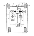
HEV(Hybrid Electrical Vehicle:ハイブリッド電気自動車)は、内燃機関(以下「エンジン」という)及び/又は電動機(以下「モータ」という)の駆動力によって走行する。図1は、HEVの内部構成の一例を示すブロック図である。図1に示すHEV(以下、単に「車両」という。)は、駆動源としてのエンジン(ENG)6と、駆動源としてのモータ(MOT)7と、バッテリ3と、インバータ(INV)101と、変速機(T/M)20と、トルクセンサ103と、制御装置2とを備える。   An HEV (Hybrid Electrical Vehicle) travels by the driving force of an internal combustion engine (hereinafter referred to as “engine”) and / or an electric motor (hereinafter referred to as “motor”). FIG. 1 is a block diagram showing an example of the internal configuration of the HEV. HEV (hereinafter simply referred to as “vehicle”) shown in FIG. 1 includes an engine (ENG) 6 as a drive source, a motor (MOT) 7 as a drive source, a battery 3, an inverter (INV) 101, A transmission (T / M) 20, a torque sensor 103, and a control device 2 are provided.

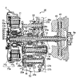
以下、各構成要素の関係と変速機20の内部構成等について、図2及び図3を参照しながら説明する。図2は、モータ及び変速機の断面図である。また、図3は、モータ及び変速機の内部構成の概念図である。   Hereinafter, the relationship between the components and the internal configuration of the transmission 20 will be described with reference to FIGS. 2 and 3. FIG. 2 is a cross-sectional view of the motor and the transmission. FIG. 3 is a conceptual diagram of the internal configuration of the motor and the transmission.

エンジン6は、例えばガソリンエンジン又はディーゼルエンジンであり、このエンジン6のクランク軸6aには、変速機20の第1クラッチ41(第1断接手段)と第2クラッチ(第2断接手段)42が設けられている。   The engine 6 is, for example, a gasoline engine or a diesel engine. A first clutch 41 (first connecting / disconnecting means) 42 and a second clutch (second connecting / disconnecting means) 42 of the transmission 20 are connected to the crankshaft 6 a of the engine 6. Is provided.

モータ7は、3相ブラシレスDCモータであり3n個の電機子71aで構成されたステータ71と、このステータ71に対向するように配置されたロータ72とを有している。各電機子71aは、鉄芯71bと、この鉄芯71bに巻き回されたコイル71cで構成されており、不図示のケーシングに固定され、回転軸を中心に周方向にほぼ等間隔で並んでいる。3n個のコイル71cは、n組のU相、V相、W相の3相コイルを構成している。   The motor 7 is a three-phase brushless DC motor, and includes a stator 71 composed of 3n armatures 71 a and a rotor 72 disposed so as to face the stator 71. Each armature 71a includes an iron core 71b and a coil 71c wound around the iron core 71b. The armature 71a is fixed to a casing (not shown) and is arranged at substantially equal intervals in the circumferential direction around the rotation axis. Yes. The 3n coils 71c constitute n sets of U-phase, V-phase, and W-phase three-phase coils.

ロータ72は、鉄芯72aと、回転軸を中心にほぼ等間隔で並んだn個の永久磁石72bを有しており、隣り合う各2つの永久磁石72bの極性は、互いに異なっている。鉄芯72aを固定する固定部72cは、中空円筒状を有し、後述する遊星歯車機構30のリングギヤ35の外周側に配置され、遊星歯車機構30のサンギヤ32に連結されている。これにより、ロータ72は、遊星歯車機構30のサンギヤ32と一体に回転するように構成されている。   The rotor 72 has an iron core 72a and n permanent magnets 72b arranged at almost equal intervals around the rotation axis, and the polarities of two adjacent permanent magnets 72b are different from each other. The fixing portion 72c for fixing the iron core 72a has a hollow cylindrical shape, is disposed on the outer peripheral side of the ring gear 35 of the planetary gear mechanism 30 described later, and is connected to the sun gear 32 of the planetary gear mechanism 30. Accordingly, the rotor 72 is configured to rotate integrally with the sun gear 32 of the planetary gear mechanism 30.

遊星歯車機構30は、サンギヤ32と、このサンギヤ32と同軸上に配置され、かつ、このサンギヤ32の周囲を取り囲むように配置されたリングギヤ35と、サンギヤ32とリングギヤ35に噛合されたプラネタリギヤ34と、このプラネタリギヤ34を自転可能、かつ、公転可能に支持するキャリア36とを有している。このようにして、サンギヤ32とリングギヤ35とキャリア36が、相互に差動回転自在に構成されている。   The planetary gear mechanism 30 includes a sun gear 32, a ring gear 35 that is arranged coaxially with the sun gear 32 and that surrounds the sun gear 32, and a planetary gear 34 that meshes with the sun gear 32 and the ring gear 35. And a carrier 36 that supports the planetary gear 34 so as to be capable of rotating and revolving. In this way, the sun gear 32, the ring gear 35, and the carrier 36 are configured to be differentially rotatable with respect to each other.

リングギヤ35には、同期機構(シンクロナイザー機構)を有しリングギヤ35の回転を停止(ロック)可能に構成されたロック機構61(シンクロ機構)が設けられている。なお、ロック機構61の代わりにブレーキ機構を用いてもよい。   The ring gear 35 is provided with a lock mechanism 61 (synchronization mechanism) that has a synchronization mechanism (synchronizer mechanism) and is configured to stop (lock) rotation of the ring gear 35. A brake mechanism may be used instead of the lock mechanism 61.

図1に示すように、モータ7は、インバータ101を介してバッテリ3に接続されている。バッテリ3は、直列に接続された複数の蓄電セルを有し、例えば100〜200Vの高電圧を供給する。蓄電セルは、例えば、リチウムイオン電池やニッケル水素電池である。インバータ101は、バッテリ3からの直流電圧を交流電圧に変換して3相電流をモータ7に供給する。また、インバータ101は、モータ7の回生動作時に入力される交流電圧を直流電圧に変換してバッテリ3に充電する。したがって、モータ7は、バッテリ3から供給された電力によって駆動され、また、減速走行時における駆動輪DW,DWの回転やエンジン6の動力により回生発電を行って、バッテリ3の充電(エネルギー回収)を行うことが可能である。   As shown in FIG. 1, the motor 7 is connected to the battery 3 via the inverter 101. The battery 3 has a plurality of power storage cells connected in series, and supplies a high voltage of 100 to 200 V, for example. The storage cell is, for example, a lithium ion battery or a nickel metal hydride battery. Inverter 101 converts a DC voltage from battery 3 into an AC voltage and supplies a three-phase current to motor 7. Further, the inverter 101 converts the AC voltage input during the regenerative operation of the motor 7 into a DC voltage and charges the battery 3. Therefore, the motor 7 is driven by the electric power supplied from the battery 3 and performs regenerative power generation by the rotation of the drive wheels DW and DW and the power of the engine 6 at the time of decelerating traveling to charge the battery 3 (energy recovery). Can be done.

変速機20は、エンジン6及び/又はモータ7からの動力を駆動輪DW,DWに伝達するための、いわゆるツインクラッチ式変速機である。変速機20は、前述した第1クラッチ41及び第2クラッチ42と、遊星歯車機構30と、後述する複数の変速ギヤ群とを備える。   The transmission 20 is a so-called twin clutch transmission for transmitting the power from the engine 6 and / or the motor 7 to the drive wheels DW and DW. The transmission 20 includes the first clutch 41 and the second clutch 42 described above, a planetary gear mechanism 30, and a plurality of transmission gear groups described later.

より具体的に、変速機20は、エンジン6のクランク軸6aと同軸(回転軸線A1)上に配置された第1主軸11(第1の入力軸)と、第2主軸12と、連結軸13と、回転軸線A1と平行に配置された回転軸線B1を中心として回転自在なカウンタ軸14(出力軸)と、回転軸線A1と平行に配置された回転軸線C1を中心として回転自在な第1中間軸15と、回転軸線A1と平行に配置された回転軸線D1を中心として回転自在な第2中間軸16(第2の入力軸)と、回転軸線A1と平行に配置された回転軸線E1を中心として回転自在なリバース軸17を備えている。   More specifically, the transmission 20 includes a first main shaft 11 (first input shaft) disposed on the same axis (rotation axis A1) as the crank shaft 6a of the engine 6, a second main shaft 12, and a connecting shaft 13. A counter shaft 14 (output shaft) rotatable around a rotation axis B1 arranged in parallel with the rotation axis A1, and a first intermediate rotatable around a rotation axis C1 arranged in parallel with the rotation axis A1. Centered on a shaft 15, a second intermediate shaft 16 (second input shaft) rotatable around a rotation axis D1 arranged in parallel with the rotation axis A1, and a rotation axis E1 arranged in parallel with the rotation axis A1 Is provided with a rotatable reverse shaft 17.

第1主軸11には、エンジン6側に第1クラッチ41が設けられ、エンジン6側とは反対側に遊星歯車機構30のサンギヤ32とモータ7のロータ72が取り付けられている。従って、第1主軸11は、第1クラッチ41によって選択的にエンジン6のクランク軸6aと連結されるとともにモータ7と直結され、エンジン6及び/又はモータ7の動力がサンギヤ32に伝達されるように構成されている。   The first main shaft 11 is provided with a first clutch 41 on the engine 6 side, and a sun gear 32 of the planetary gear mechanism 30 and a rotor 72 of the motor 7 are attached to the side opposite to the engine 6 side. Accordingly, the first main shaft 11 is selectively connected to the crankshaft 6 a of the engine 6 by the first clutch 41 and directly connected to the motor 7 so that the power of the engine 6 and / or the motor 7 is transmitted to the sun gear 32. It is configured.

第2主軸12は、第1主軸11より短く中空に構成されており、第1主軸11のエンジン6側の周囲を覆うように相対回転自在に配置されている。また、第2主軸12には、エンジン6側に第2クラッチ42が設けられ、エンジン6側とは反対側にアイドル駆動ギヤ27aが一体に取り付けられている。従って、第2主軸12は、第2クラッチ42によって選択的にエンジン6のクランク軸6aと連結され、エンジン6の動力がアイドル駆動ギヤ27aへ伝達されるように構成されている。   The second main shaft 12 is configured to be shorter and hollow than the first main shaft 11, and is disposed so as to be relatively rotatable so as to cover the periphery of the first main shaft 11 on the engine 6 side. The second main shaft 12 is provided with a second clutch 42 on the engine 6 side, and an idle drive gear 27a is integrally attached to the opposite side to the engine 6 side. Accordingly, the second main shaft 12 is selectively connected to the crankshaft 6a of the engine 6 by the second clutch 42, and the power of the engine 6 is transmitted to the idle drive gear 27a.

連結軸13は、第1主軸11より短く中空に構成されており、第1主軸11のエンジン6側とは反対側の周囲を覆うように相対回転自在に配置されている。また、連結軸13には、エンジン6側に第3速用駆動ギヤ23aが一体に取り付けられ、エンジン6側とは反対側に遊星歯車機構30のキャリア36が一体に取り付けられている。従って、プラネタリギヤ34の公転により連結軸13に取り付けられたキャリア36と第3速用駆動ギヤ23aが一体に回転するように構成されている。   The connecting shaft 13 is configured to be shorter and hollow than the first main shaft 11, and is disposed so as to be relatively rotatable so as to cover the periphery of the first main shaft 11 on the side opposite to the engine 6. Further, a third speed drive gear 23 a is integrally attached to the connecting shaft 13 on the engine 6 side, and a carrier 36 of the planetary gear mechanism 30 is integrally attached to the opposite side of the engine 6 side. Therefore, the carrier 36 attached to the connecting shaft 13 and the third-speed drive gear 23a are configured to rotate integrally by the revolution of the planetary gear 34.

さらに、第1主軸11には、第1主軸11と相対回転自在に第5速用駆動ギヤ25aが設けられるとともに、第1主軸11と一体に回転するリバース従動ギヤ28bが取り付けられている。さらに第3速用駆動ギヤ23aと第5速用駆動ギヤ25aとの間には、第1主軸11と第3速用駆動ギヤ23a又は第5速用駆動ギヤ25aとを連結又は開放する第1変速用シフター51(第1同期装置)が設けられている。そして、第1変速用シフター51が第3速用接続位置でインギヤするときには、第1主軸11と第3速用駆動ギヤ23aが連結して一体に回転し、第5速用接続位置でインギヤするときには、第1主軸11と第5速用駆動ギヤ25aが一体に回転し、第1変速用シフター51がニュートラル位置にあるときには、第1主軸11は第3速用駆動ギヤ23aと第5速用駆動ギヤ25aに対し相対回転する。なお、第1主軸11と第3速用駆動ギヤ23aが一体に回転するとき、第1主軸11に取り付けられたサンギヤ32と第3速用駆動ギヤ23aに連結軸13で連結されたキャリア36が一体に回転するとともに、リングギヤ35も一体に回転し、遊星歯車機構30が一体となる。また、第1変速用シフター51がニュートラル位置にあって、ロック機構61が接続されると、リングギヤ35がロックされ、サンギヤ32の回転が減速されてキャリア36に伝達される。   Further, the first main shaft 11 is provided with a fifth speed drive gear 25 a that is rotatable relative to the first main shaft 11, and a reverse driven gear 28 b that rotates integrally with the first main shaft 11. Further, a first main shaft 11 and a third speed drive gear 23a or a fifth speed drive gear 25a are connected or released between the third speed drive gear 23a and the fifth speed drive gear 25a. A shift shifter 51 (first synchronization device) is provided. When the first speed-shifting shifter 51 is in-gear at the third speed connection position, the first main shaft 11 and the third speed drive gear 23a are connected to rotate integrally and in-gear at the fifth speed connection position. Sometimes, the first main shaft 11 and the fifth speed drive gear 25a rotate integrally, and when the first speed change shifter 51 is in the neutral position, the first main shaft 11 has the third speed drive gear 23a and the fifth speed drive gear 25a. It rotates relative to the drive gear 25a. When the first main shaft 11 and the third speed drive gear 23a rotate together, the sun gear 32 attached to the first main shaft 11 and the carrier 36 connected to the third speed drive gear 23a by the connecting shaft 13 are provided. While rotating integrally, the ring gear 35 also rotates together, and the planetary gear mechanism 30 is united. When the first shifter 51 is in the neutral position and the lock mechanism 61 is connected, the ring gear 35 is locked and the rotation of the sun gear 32 is decelerated and transmitted to the carrier 36.

第1中間軸15には、第2主軸12に取り付けられたアイドル駆動ギヤ27aと噛合する第1アイドル従動ギヤ27bが一体に取り付けられている。   A first idle driven gear 27 b that meshes with an idle drive gear 27 a attached to the second main shaft 12 is integrally attached to the first intermediate shaft 15.

第2中間軸16には、第1中間軸15に取り付けられた第1アイドル従動ギヤ27bと噛合する第2アイドル従動ギヤ27cが一体に取り付けられている。第2アイドル従動ギヤ27cは、前述したアイドル駆動ギヤ27aと第1アイドル従動ギヤ27bとともに第1アイドルギヤ列27Aを構成している。また、第2中間軸16には、第1主軸11周りに設けられた第3速用駆動ギヤ23aと第5速用駆動ギヤ25aと対応する位置にそれぞれ第2中間軸16と相対回転可能な第2速用駆動ギヤ22aと第4速用駆動ギヤ24aとが設けられている。さらに第2中間軸16には、第2速用駆動ギヤ22aと第4速用駆動ギヤ24aとの間に、第2中間軸16と第2速用駆動ギヤ22a又は第4速用駆動ギヤ24aとを連結又は開放する第2変速用シフター52(第2同期装置)が設けられている。そして、第2変速用シフター52が第2速用接続位置でインギヤするときには、第2中間軸16と第2速用駆動ギヤ22aとが一体に回転し、第2変速用シフター52が第4速用接続位置でインギヤするときには、第2中間軸16と第4速用駆動ギヤ24aとが一体に回転し、第2変速用シフター52がニュートラル位置にあるときには、第2中間軸16は第2速用駆動ギヤ22aと第4速用駆動ギヤ24aに対し相対回転する。   A second idle driven gear 27 c that meshes with a first idle driven gear 27 b attached to the first intermediate shaft 15 is integrally attached to the second intermediate shaft 16. The second idle driven gear 27c constitutes the first idle gear train 27A together with the idle drive gear 27a and the first idle driven gear 27b described above. The second intermediate shaft 16 is rotatable relative to the second intermediate shaft 16 at positions corresponding to the third speed drive gear 23a and the fifth speed drive gear 25a provided around the first main shaft 11, respectively. A second speed drive gear 22a and a fourth speed drive gear 24a are provided. Further, the second intermediate shaft 16 includes a second intermediate shaft 16 and a second speed drive gear 22a or a fourth speed drive gear 24a between the second speed drive gear 22a and the fourth speed drive gear 24a. Is provided with a second shifter 52 (second synchronizer). When the second shifter 52 shifts in-gear at the second speed connection position, the second intermediate shaft 16 and the second speed drive gear 22a rotate together, and the second shifter 52 shifts to the fourth speed. When in-gearing at the connecting position, the second intermediate shaft 16 and the fourth speed drive gear 24a rotate together, and when the second shifter shifter 52 is in the neutral position, the second intermediate shaft 16 is in the second speed. The drive gear 22a and the fourth speed drive gear 24a rotate relative to each other.

カウンタ軸14には、エンジン6側とは反対側から順に第1共用従動ギヤ23bと、第2共用従動ギヤ24bと、パーキングギヤ21と、ファイナルギヤ26aとが一体に取り付けられている。
ここで、第1共用従動ギヤ23bは、連結軸13に取り付けられた第3速用駆動ギヤ23aと噛合して第3速用駆動ギヤ23aと共に第3速用ギヤ対23を構成し、第2中間軸16に設けられた第2速用駆動ギヤ22aと噛合して第2速用駆動ギヤ22aと共に第2速用ギヤ対22を構成する。
第2共用従動ギヤ24bは、第1主軸11に設けられた第5速用駆動ギヤ25aと噛合して第5速用駆動ギヤ25aと共に第5速用ギヤ対25を構成し、第2中間軸16に設けられた第4速用駆動ギヤ24aと噛合して第4速用駆動ギヤ24aと共に第4速用ギヤ対24を構成する。
ファイナルギヤ26aは差動ギヤ機構8と噛合して、差動ギヤ機構8は、駆動軸9,9を介して駆動輪DW,DWに連結されている。従って、カウンタ軸14に伝達された動力はファイナルギヤ26aから差動ギヤ機構8、駆動軸9,9、駆動輪DW,DWへと出力される。
A first shared driven gear 23b, a second shared driven gear 24b, a parking gear 21, and a final gear 26a are integrally attached to the counter shaft 14 in order from the side opposite to the engine 6 side.
Here, the first shared driven gear 23b meshes with the third speed drive gear 23a attached to the connecting shaft 13 to form the third speed gear pair 23 together with the third speed drive gear 23a, The second speed gear pair 22 is configured together with the second speed drive gear 22a by meshing with the second speed drive gear 22a provided on the intermediate shaft 16.
The second shared driven gear 24b meshes with the fifth speed drive gear 25a provided on the first main shaft 11 to form the fifth speed gear pair 25 together with the fifth speed drive gear 25a, and the second intermediate shaft. 16 is engaged with a fourth speed drive gear 24a to constitute a fourth speed gear pair 24 together with the fourth speed drive gear 24a.
The final gear 26 a meshes with the differential gear mechanism 8, and the differential gear mechanism 8 is connected to the drive wheels DW and DW via the drive shafts 9 and 9. Therefore, the power transmitted to the counter shaft 14 is output from the final gear 26a to the differential gear mechanism 8, the drive shafts 9, 9, and the drive wheels DW, DW.

リバース軸17には、第1中間軸15に取り付けられた第1アイドル従動ギヤ27bと噛合する第3アイドル従動ギヤ27dが一体に取り付けられている。第3アイドル従動ギヤ27dは、前述したアイドル駆動ギヤ27aと第1アイドル従動ギヤ27bとともに第2アイドルギヤ列27Bを構成している。また、リバース軸17には、第1主軸11に取り付けられた後進用従動ギヤ28bと噛合する後進用駆動ギヤ28aがリバース軸17と相対回転自在に設けられている。後進用駆動ギヤ28aは、後進用従動ギヤ28bとともに後進用ギヤ列28を構成している。さらに後進用駆動ギヤ28aのエンジン6側とは反対側にリバース軸17と後進用駆動ギヤ28aとを連結又は開放する後進用シフター53が設けられている。そして、後進用シフター53が後進用接続位置でインギヤするときには、リバース軸17と後進用駆動ギヤ28aとが一体に回転し、後進用シフター53がニュートラル位置にあるときには、リバース軸17と後進用駆動ギヤ28aとが相対回転する。   A third idle driven gear 27d that meshes with a first idle driven gear 27b attached to the first intermediate shaft 15 is integrally attached to the reverse shaft 17. The third idle driven gear 27d constitutes a second idle gear train 27B together with the above-described idle drive gear 27a and first idle driven gear 27b. The reverse shaft 17 is provided with a reverse drive gear 28 a that meshes with a reverse driven gear 28 b attached to the first main shaft 11 so as to be rotatable relative to the reverse shaft 17. The reverse drive gear 28a constitutes the reverse gear train 28 together with the reverse driven gear 28b. Further, a reverse shifter 53 for connecting or releasing the reverse shaft 17 and the reverse drive gear 28a is provided on the opposite side of the reverse drive gear 28a from the engine 6 side. When the reverse shifter 53 is in-gear at the reverse connection position, the reverse shaft 17 and the reverse drive gear 28a rotate together. When the reverse shifter 53 is at the neutral position, the reverse shaft 17 and the reverse drive The gear 28a rotates relative to the gear 28a.

なお、第1変速用シフター51、第2変速用シフター52、後進用シフター53は、接続する軸とギヤの回転数を一致させる同期機構(シンクロナイザー機構)を有するクラッチ機構を用いている。   The first shifter 51, the second shifter 52, and the reverse shifter 53 use a clutch mechanism having a synchronization mechanism (synchronizer mechanism) for matching the shaft to be connected and the rotational speed of the gear.

このように構成された変速機20は、2つの変速軸の一方の変速軸である第1主軸11上に第3速用駆動ギヤ23aと第5速用駆動ギヤ25aからなる奇数段ギヤ群(第1ギヤ群)が設けられ、2つの変速軸の他方の変速軸である第2中間軸16上に第2速用駆動ギヤ22aと第4速用駆動ギヤ24aからなる偶数段ギヤ群(第2ギヤ群)が設けられる。なお、変速機20の偶数段ギヤ群が第6速用駆動ギヤをさらに有し、かつ、奇数段ギヤ群が第7速用駆動ギヤをさらに有しても良い。   The transmission 20 configured as described above has an odd-numbered gear group consisting of a third speed drive gear 23a and a fifth speed drive gear 25a on the first main shaft 11, which is one of the two transmission shafts. A first gear group) and an even-stage gear group (first gear group) composed of a second-speed drive gear 22a and a fourth-speed drive gear 24a on the second intermediate shaft 16, which is the other of the two transmission shafts. 2 gear groups) are provided. The even-numbered gear group of the transmission 20 may further include a sixth-speed driving gear, and the odd-numbered gear group may further include a seventh-speed driving gear.

本実施形態の変速機20は、上記説明した構成であるため、以下説明する第1〜第5の伝達経路を有する。
(1)第1伝達経路は、エンジン6のクランク軸6aが、第1主軸11、遊星歯車機構30、連結軸13、第3速用ギヤ対23(第3速用駆動ギヤ23a、第1共用従動ギヤ23b)、カウンタ軸14、ファイナルギヤ26a、差動ギヤ機構8、駆動軸9,9を介して、駆動輪DW,DWに連結される伝達経路である。ここで、遊星歯車機構30の減速比は、第1伝達経路を介して駆動輪DW,DWに伝達されるエンジントルクが第1速相当となるように設定されている。即ち、遊星歯車機構30の減速比と第3速用ギヤ対23の減速比をかけ合わせた減速比が第1速相当となるように設定されている。
Since the transmission 20 of the present embodiment has the above-described configuration, the transmission 20 has first to fifth transmission paths described below.
(1) In the first transmission path, the crankshaft 6a of the engine 6 includes the first main shaft 11, the planetary gear mechanism 30, the connecting shaft 13, and the third speed gear pair 23 (third speed drive gear 23a, first common use). This is a transmission path connected to the drive wheels DW and DW via the driven gear 23b), the counter shaft 14, the final gear 26a, the differential gear mechanism 8, and the drive shafts 9 and 9. Here, the reduction gear ratio of the planetary gear mechanism 30 is set so that the engine torque transmitted to the drive wheels DW and DW via the first transmission path corresponds to the first speed. That is, the reduction ratio obtained by multiplying the reduction ratio of the planetary gear mechanism 30 and the reduction ratio of the third speed gear pair 23 is set to be equivalent to the first speed.

(2)第2伝達経路は、エンジン6のクランク軸6aが、第2主軸12、第1アイドルギヤ列27A(アイドル駆動ギヤ27a、第1アイドル従動ギヤ27b、第2アイドル従動ギヤ27c)、第2中間軸16、第2速用ギヤ対22(第2速用駆動ギヤ22a、第1共用従動ギヤ23b)又は第4速用ギヤ対24(第4速用駆動ギヤ24a、第2共用従動ギヤ24b)、カウンタ軸14、ファイナルギヤ26a、差動ギヤ機構8、駆動軸9,9を介して、駆動輪DW,DWに連結される伝達経路である。 (2) In the second transmission path, the crankshaft 6a of the engine 6 has the second main shaft 12, the first idle gear train 27A (the idle drive gear 27a, the first idle driven gear 27b, the second idle driven gear 27c), the second 2 intermediate shaft 16, second speed gear pair 22 (second speed drive gear 22a, first shared driven gear 23b) or fourth speed gear pair 24 (fourth speed drive gear 24a, second shared driven gear) 24b), a transmission path connected to the drive wheels DW and DW via the counter shaft 14, the final gear 26a, the differential gear mechanism 8, and the drive shafts 9 and 9.

(3)第3伝達経路は、エンジン6のクランク軸6aが、第1主軸11、第3速用ギヤ対23(第3速用駆動ギヤ23a、第1共用従動ギヤ23b)又は第5速用ギヤ対25(第5速用駆動ギヤ25a、第2共用従動ギヤ24b)、カウンタ軸14、ファイナルギヤ26a、差動ギヤ機構8、駆動軸9,9を介して、遊星歯車機構30を介さずに、駆動輪DW,DWに連結される伝達経路である。 (3) In the third transmission path, the crankshaft 6a of the engine 6 is used for the first main shaft 11, the third speed gear pair 23 (the third speed drive gear 23a, the first shared driven gear 23b) or the fifth speed. Through the gear pair 25 (the fifth speed drive gear 25a and the second shared driven gear 24b), the counter shaft 14, the final gear 26a, the differential gear mechanism 8, and the drive shafts 9 and 9, without the planetary gear mechanism 30. And a transmission path coupled to the drive wheels DW and DW.

(4)第4伝達経路は、モータ7が、遊星歯車機構30又は第3速用ギヤ対23(第3速用駆動ギヤ23a、第1共用従動ギヤ23b)又は第5速用ギヤ対25(第5速用駆動ギヤ25a、第2共用従動ギヤ24b)、カウンタ軸14、ファイナルギヤ26a、差動ギヤ機構8、駆動軸9,9を介して、駆動輪DW,DWに連結される伝達経路である。 (4) In the fourth transmission path, the motor 7 is connected to the planetary gear mechanism 30 or the third speed gear pair 23 (third speed drive gear 23a, first shared driven gear 23b) or fifth speed gear pair 25 ( 5th speed drive gear 25a, second shared driven gear 24b), counter shaft 14, final gear 26a, differential gear mechanism 8, and drive shafts 9 and 9 are connected to drive wheels DW and DW. It is.

(5)第5伝達経路は、エンジン6のクランク軸6aが、第2主軸12、第2アイドルギヤ列27B(アイドル駆動ギヤ27a、第1アイドル従動ギヤ27b、第3アイドル従動ギヤ27d)、リバース軸17、後進用ギヤ列28(後進用駆動ギヤ28a、後進用従動ギヤ28b)、遊星歯車機構30、連結軸13、第3速用ギヤ対23(第3速用駆動ギヤ23a、第1共用従動ギヤ23b)、カウンタ軸14、ファイナルギヤ26a、差動ギヤ機構8、駆動軸9,9を介して、駆動輪DW,DWに連結される伝達経路である。 (5) In the fifth transmission path, the crankshaft 6a of the engine 6 is connected to the second main shaft 12, the second idle gear train 27B (idle drive gear 27a, first idle driven gear 27b, third idle driven gear 27d), reverse Shaft 17, reverse gear train 28 (reverse drive gear 28a, reverse driven gear 28b), planetary gear mechanism 30, connecting shaft 13, third speed gear pair 23 (third speed drive gear 23a, first common use) This is a transmission path connected to the drive wheels DW and DW via the driven gear 23b), the counter shaft 14, the final gear 26a, the differential gear mechanism 8, and the drive shafts 9 and 9.

トルクセンサ103は、変速機20が有するカウンタ軸14の出力トルクを検出する。トルクセンサ103の検出結果を示す情報は、制御装置2に送られる。   The torque sensor 103 detects the output torque of the counter shaft 14 included in the transmission 20. Information indicating the detection result of the torque sensor 103 is sent to the control device 2.

制御装置2は、バッテリ3からモータ7への電力供給及びモータ7からバッテリ3へのエネルギー回生を制御する。また、制御装置2は、加速要求、制動要求、エンジン回転数、モータ回転数、モータ温度、第1主軸11及び第2主軸12の各回転数、カウンタ軸14等の回転数、車速、シフトポジション、並びに、SOC(State of Charge)などに関する情報が入力される。さらに、制御装置2には、トルクセンサ103が検出したカウンタ軸14のトルクを示す情報も入力される。一方、制御装置2は、エンジン6を制御する信号、モータ7を制御する信号、バッテリ3の発電状態・充電状態・放電状態などを示す信号、第1変速用シフター51、第2変速用シフター52及び後進用シフター53を制御する信号、並びに、ロック機構61の接続(ロック)と開放(ニュートラル)を制御する信号などを出力する。   The control device 2 controls power supply from the battery 3 to the motor 7 and energy regeneration from the motor 7 to the battery 3. Further, the control device 2 performs acceleration request, braking request, engine rotation speed, motor rotation speed, motor temperature, rotation speeds of the first main spindle 11 and the second main spindle 12, rotation speed of the counter shaft 14, etc., vehicle speed, shift position. In addition, information on SOC (State of Charge) and the like is input. Furthermore, information indicating the torque of the counter shaft 14 detected by the torque sensor 103 is also input to the control device 2. On the other hand, the control device 2 includes a signal for controlling the engine 6, a signal for controlling the motor 7, a signal indicating the power generation state / charge state / discharge state of the battery 3, the first shifter shifter 51, and the second shifter shifter 52. And a signal for controlling the reverse shifter 53, a signal for controlling the connection (lock) and release (neutral) of the lock mechanism 61, and the like.

制御装置2が、変速機20の第1クラッチ41及び第2クラッチ42の断接を制御するとともに、ロック機構61、第1変速用シフター51、第2変速用シフター52及び後進用シフター53の接続位置を制御(プレシフト)することにより、車両はエンジン6で第1〜第5速走行及び後進走行を行うことができる。   The control device 2 controls connection / disconnection of the first clutch 41 and the second clutch 42 of the transmission 20 and connects the lock mechanism 61, the first shifter 51, the second shifter 52, and the reverse shifter 53. By controlling (pre-shifting) the position, the vehicle can perform first to fifth speed traveling and reverse traveling with the engine 6.

車両が第1速走行を行う際、制御装置2が第1クラッチ41を締結しロック機構61を接続することで第1伝達経路を介して駆動力が駆動輪DW,DWに伝達される。また、車両が第2速走行を行う際、制御装置2が第2クラッチ42を締結して第2変速用シフター52を第2速用接続位置でインギヤすることで第2伝達経路を介して駆動力が駆動輪DW,DWに伝達される。また、車両が第3速走行を行う際、制御装置2が第1クラッチ41を締結して第1変速用シフター51を第3速用接続位置でインギヤすることで第3伝達経路を介して駆動力が駆動輪DW,DWに伝達される。   When the vehicle travels at the first speed, the control device 2 engages the first clutch 41 and connects the lock mechanism 61 so that the driving force is transmitted to the drive wheels DW and DW via the first transmission path. Further, when the vehicle travels at the second speed, the control device 2 is driven through the second transmission path by engaging the second clutch 42 and in-gearing the second shifter shifter 52 at the second speed connection position. Force is transmitted to the drive wheels DW and DW. Further, when the vehicle travels at the third speed, the control device 2 is driven through the third transmission path by engaging the first clutch 41 and in-gearing the first shifter 51 at the third speed connection position. Force is transmitted to the drive wheels DW and DW.

また、車両が第4速走行を行う際、制御装置2が第1クラッチ41を締結して第2変速用シフター52を第4速用接続位置でインギヤすることで第2伝達経路を介して駆動力が駆動輪DW,DWに伝達される。また、車両が第5速走行を行う際、制御装置2が第1変速用シフター51を第5速用接続位置でインギヤすることで第3伝達経路を介して駆動力が駆動輪DW,DWに伝達される。さらに、車両が後進走行を行う際、制御装置2が第2クラッチ42を締結して後進用シフター53を接続することで、第5伝達経路を介して後進走行が行われる。   Further, when the vehicle travels in the fourth speed, the control device 2 is driven through the second transmission path by engaging the first clutch 41 and in-gearing the second shifter shifter 52 at the fourth speed connection position. Force is transmitted to the drive wheels DW and DW. Further, when the vehicle travels at the fifth speed, the control device 2 in-gears the first shifter shifter 51 at the fifth speed connection position so that the driving force is applied to the drive wheels DW and DW via the third transmission path. Communicated. Furthermore, when the vehicle travels backward, the control device 2 engages the second clutch 42 and connects the reverse shifter 53, whereby the reverse travel is performed via the fifth transmission path.

また、エンジン走行中にロック機構61を接続したり、第1及び第2変速用シフター51、52をプレシフトすることでモータ7でアシストしたり回生したり、さらにアイドリング中であってもエンジン6をモータ7で始動したりバッテリ3を充電することもできる。さらに、第1及び第2クラッチ41、42を切断してモータ7でEV走行を行うこともできる。EV走行の走行モードとしては、第1及び第2クラッチ41、42を切断して、ロック機構61を接続することで第4伝達経路を介して走行する第1速EVモードと、第1変速用シフター51を第3速用接続位置でインギヤすることで第4伝達経路を介して走行する第3速EVモードと、第1変速用シフター51を第5速用接続位置でインギヤすることで第4伝達経路を介して走行する第5速EVモードとが存在する。   Further, the engine 6 can be assisted or regenerated by connecting the lock mechanism 61 while the engine is running, the first and second shifter shifters 51 and 52 are pre-shifted, and further idling. The motor 7 can be started and the battery 3 can be charged. Further, the first and second clutches 41 and 42 can be disconnected and the EV 7 can be driven by the motor 7. The EV travel mode includes a first speed EV mode in which the first and second clutches 41 and 42 are disconnected and the lock mechanism 61 is connected to travel through the fourth transmission path, and the first speed change mode. The third speed EV mode that travels through the fourth transmission path by in-gearing the shifter 51 at the third-speed connection position, and the fourth speed by in-gearing the first shifter 51 at the fifth-speed connection position. There is a fifth speed EV mode that travels via a transmission path.

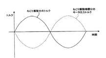
上述したようにドライバーのアクセル操作による加速時には、エンジン6又はモータ7から出力されるトルクが増加するために、変速機20のカウンタ軸14にトルクのねじり振動が発生する。本実施形態の制御装置2は、トルクセンサ103から入力された情報に基づいて、変速機20のカウンタ軸14に発生するトルクのねじり振動を打ち消すよう、モータ7の動作を制御する。例えば、図4の実線に示すように、ねじり振動によって生じたトルクの変化が正弦波状であるとき、制御装置2は、図4に点線で示すように、ねじり振動によって生じたトルクとは逆位相のトルクを出力するようモータ7を制御する。なお、モータ7が負のトルクを出力することは、モータ7を回生動作させることを同義である。   As described above, at the time of acceleration due to the accelerator operation of the driver, the torque output from the engine 6 or the motor 7 increases, so that a torsional vibration of torque occurs in the counter shaft 14 of the transmission 20. The control device 2 of the present embodiment controls the operation of the motor 7 so as to cancel the torsional vibration of the torque generated in the counter shaft 14 of the transmission 20 based on the information input from the torque sensor 103. For example, as shown by the solid line in FIG. 4, when the change in torque caused by the torsional vibration is sinusoidal, the control device 2 has a phase opposite to that of the torque produced by the torsional vibration as shown by the dotted line in FIG. The motor 7 is controlled so as to output the torque. Note that outputting a negative torque by the motor 7 is synonymous with causing the motor 7 to perform a regenerative operation.

以下、制御装置2によるねじり振動の補償制御について詳細に説明する。制御装置2は、変速機20が上記説明した第1〜第5伝達経路の内、どの伝達経路で動力を伝達しており、車両が第何速走行を行っているかに応じて、モータ7の動力を制御する。例えば、エンジン6からの動力が第1伝達経路で伝達されており、車両が第1速走行を行っているとき、動力は第1速相当の減速比でカウンタ軸14に伝達されている。このとき、制御装置2は、ねじり振動分のトルクを第1速の減速比で割った逆位相の動力をモータ7が出力するよう制御する。   Hereinafter, torsional vibration compensation control by the control device 2 will be described in detail. The control device 2 controls the motor 7 according to which transmission path the transmission 20 transmits power from among the first to fifth transmission paths described above, and how fast the vehicle is traveling. Control power. For example, when the power from the engine 6 is transmitted through the first transmission path and the vehicle is traveling at the first speed, the power is transmitted to the counter shaft 14 at a reduction ratio corresponding to the first speed. At this time, the control device 2 controls the motor 7 to output the power in the opposite phase obtained by dividing the torque for the torsional vibration by the reduction ratio of the first speed.

また、エンジン6からの動力が第2伝達経路で伝達されており、第2クラッチ42が締結され第2変速用シフター52が第2速用接続位置でインギヤされているため車両が第2速走行を行っているとき、エンジン6からの動力は第2速相当の減速比でカウンタ軸14に伝達されている。但し、このとき、モータ7とカウンタ軸14の間の経路は切断されている。したがって、本実施形態では、制御装置2は、ロック機構61を接続(1速プレシフト)するか、第1変速用シフター51を第3速用接続位置でインギヤ(3速プレシフト)するよう変速機20を制御することにより、モータ7とカウンタ軸14の間の経路を接続する。このとき、制御装置2は、ねじり振動分のトルクを第2速の減速比で割った逆位相の動力をモータ7が出力するよう制御する。   Further, since the power from the engine 6 is transmitted through the second transmission path, the second clutch 42 is engaged, and the second shifter 52 is in-gear at the second speed connection position, so that the vehicle travels at the second speed. When the engine is running, the power from the engine 6 is transmitted to the counter shaft 14 at a reduction ratio corresponding to the second speed. However, at this time, the path between the motor 7 and the counter shaft 14 is disconnected. Therefore, in the present embodiment, the control device 2 connects the lock mechanism 61 (first speed preshift) or shifts the first shifter 51 in-gear (third speed preshift) at the third speed connection position. Is connected to connect the path between the motor 7 and the counter shaft 14. At this time, the control device 2 controls the motor 7 to output the power in the opposite phase obtained by dividing the torque for the torsional vibration by the reduction ratio of the second speed.

また、エンジン6からの動力が第3伝達経路で伝達されており、第1クラッチ41が締結され第1変速用シフター51が第3速用接続位置でインギヤされているため車両が第3速走行を行っているとき、エンジン6からの動力は第3速相当の減速比でカウンタ軸14に伝達されている。したがって、制御装置2は、ねじり振動分のトルクを第3速の減速比で割った逆位相の動力をモータ7が出力するよう制御する。   Further, since the power from the engine 6 is transmitted through the third transmission path, the first clutch 41 is engaged, and the first shifter 51 is in-gear at the third speed connection position, so that the vehicle travels at the third speed. When the engine is running, the power from the engine 6 is transmitted to the countershaft 14 at a reduction ratio corresponding to the third speed. Therefore, the control device 2 controls the motor 7 to output power in the opposite phase obtained by dividing the torque for torsional vibration by the reduction ratio of the third speed.

また、エンジン6からの動力が第2伝達経路で伝達されており、第2クラッチ42が締結され第2変速用シフター52が第4速用接続位置でインギヤされているため車両が第4速走行を行っているとき、エンジン6からの動力は第4速相当の減速比でカウンタ軸14に伝達されている。但し、このとき、モータ7とカウンタ軸14の間の経路は切断されている。したがって、本実施形態では、制御装置2は、第1変速用シフター51を第3速用接続位置でインギヤ(3速プレシフト)するか、第1変速用シフター51を第5速用接続位置でインギヤ(5速プレシフト)するよう変速機20を制御することにより、モータ7とカウンタ軸14の間の経路を接続する。このとき、制御装置2は、ねじり振動分のトルクを第4速の減速比で割った逆位相の動力をモータ7が出力するよう制御する。   Further, since the power from the engine 6 is transmitted through the second transmission path, the second clutch 42 is engaged, and the second shifter shifter 52 is in-gear at the fourth speed connection position, so that the vehicle travels at the fourth speed. Is being performed, the power from the engine 6 is transmitted to the countershaft 14 at a reduction ratio corresponding to the fourth speed. However, at this time, the path between the motor 7 and the counter shaft 14 is disconnected. Therefore, in the present embodiment, the control device 2 in-gears the first speed-shifting shifter 51 at the third-speed connection position (three-speed preshift) or moves the first speed-shifting shifter 51 in-gear at the fifth-speed connection position. The path between the motor 7 and the counter shaft 14 is connected by controlling the transmission 20 to perform (5-speed preshift). At this time, the control device 2 controls the motor 7 to output the power in the opposite phase obtained by dividing the torque for torsional vibration by the reduction ratio of the fourth speed.

また、エンジン6からの動力が第3伝達経路で伝達されており、第1クラッチ41が締結され第1変速用シフター51が第5速用接続位置でインギヤされているため車両が第5速走行を行っているとき、エンジン6からの動力は第5速相当の減速比でカウンタ軸14に伝達されている。したがって、制御装置2は、ねじり振動分のトルクを第5速の減速比で割った逆位相の動力をモータ7が出力するよう制御する。   Further, since the power from the engine 6 is transmitted through the third transmission path, the first clutch 41 is engaged, and the first shifter 51 is in gear at the fifth speed connection position, so that the vehicle travels at the fifth speed. Is being performed, the power from the engine 6 is transmitted to the countershaft 14 at a reduction ratio corresponding to the fifth speed. Therefore, the control device 2 controls the motor 7 to output power in the opposite phase obtained by dividing the torque for torsional vibration by the reduction ratio of the fifth speed.

なお、モータ7からの動力が第4伝達経路で伝達されているとき、制御装置2は、ねじり振動分のトルクを選択中の変速に対応する減速比で割った逆位相の動力でモータ7の出力を補償しても良い。   When the power from the motor 7 is transmitted through the fourth transmission path, the control device 2 uses the reverse phase power obtained by dividing the torque for the torsional vibration by the reduction ratio corresponding to the selected speed change. The output may be compensated.

以上説明したように、本実施形態によれば、変速機20のカウンタ軸14にトルクのねじり振動が発生しても、モータ7の出力又は回生動作によって当該ねじり振動によるトルクの変位を打ち消すことができる。   As described above, according to the present embodiment, even if a torque torsional vibration is generated on the counter shaft 14 of the transmission 20, the torque displacement due to the torsional vibration can be canceled by the output of the motor 7 or the regenerative operation. it can.

2 制御装置
3 バッテリ
6 エンジン(内燃機関)
7 モータ(電動機)
11 第1主軸(第1の入力軸)
14 カウンタ軸(出力軸)
16 第2中間軸(第2の入力軸)
20 変速機
22a 第2速用駆動ギヤ
23a 第3速用駆動ギヤ
23b 第1共用従動ギヤ
24a 第4速用駆動ギヤ
24b 第2共用従動ギヤ
25a 第5速用駆動ギヤ
30 遊星歯車機構
41 第1クラッチ(第1断接手段)
42 第2クラッチ(第2断接手段)
51 第1変速用シフター(第1同期装置)
52 第2変速用シフター(第2同期装置)
61 ロック機構(シンクロ機構)
101 インバータ
103 トルクセンサ
2 Control device 3 Battery 6 Engine (internal combustion engine)
7 Motor (electric motor)
11 First spindle (first input shaft)
14 Counter shaft (output shaft)
16 Second intermediate shaft (second input shaft)
20 Transmission 22a Second speed drive gear 23a Third speed drive gear 23b First shared driven gear 24a Fourth speed drive gear 24b Second shared driven gear 25a Fifth speed drive gear 30 Planetary gear mechanism 41 First Clutch (first connecting / disconnecting means)
42 Second clutch (second connecting / disconnecting means)
51 First shifter (first synchronizer)
52 Second shifter (second synchronizer)
61 Lock mechanism (synchro mechanism)
101 Inverter 103 Torque sensor

Claims (3)

内燃機関と、
電動機と、
前記電動機に接続されるとともに第1断接手段を介して選択的に前記内燃機関に接続される第1入力軸と、第2断接手段を介して選択的に前記内燃機関に接続される第2入力軸と、被駆動部に動力を出力する出力軸と、前記第1入力軸上に配置され第1同期装置を介して前記第1入力軸に選択的に連結される複数のギヤよりなる第1ギヤ群と、前記第2入力軸上に配置され第2同期装置を介して前記第2入力軸に選択的に連結される複数のギヤよりなる第2ギヤ群と、前記出力軸上に配置され前記第1ギヤ群のギヤと前記第2ギヤ群のギヤとが噛合する複数のギヤよりなる第3ギヤ群と、を有する変速機と、を備えた車両用駆動装置の制御装置であって、
前記変速機の前記出力軸が出力するトルクを検出するトルク検出部と、
前記変速機で選択されている動力の伝達経路に応じて、前記トルク検出部によって検出されたねじり振動によるトルクの変位を補償する分のトルクを発生するよう前記電動機を制御する制御部と、
を備えたことを特徴とする車両用駆動装置の制御装置。
An internal combustion engine;
An electric motor,
A first input shaft connected to the electric motor and selectively connected to the internal combustion engine via first connecting / disconnecting means, and a first input shaft selectively connected to the internal combustion engine via second connecting / disconnecting means. 2 input shafts, an output shaft for outputting power to the driven part, and a plurality of gears arranged on the first input shaft and selectively connected to the first input shaft via a first synchronization device A first gear group, a second gear group comprising a plurality of gears arranged on the second input shaft and selectively coupled to the second input shaft via a second synchronization device; and on the output shaft And a transmission having a third gear group including a plurality of gears arranged and meshed with the gears of the first gear group and the gears of the second gear group. And
A torque detector for detecting torque output by the output shaft of the transmission;
A control unit that controls the electric motor to generate torque corresponding to the displacement of torque caused by torsional vibration detected by the torque detection unit according to a power transmission path selected by the transmission;
A control device for a vehicle drive device, comprising:
請求項1に記載の車両用駆動装置の制御装置であって、
前記制御部は、前記トルク検出部が検出したトルクの変位とは逆位相のトルクを発生するよう前記電動機を制御することを特徴とする車両用駆動装置の制御装置。
A control device for a vehicle drive device according to claim 1,
The control unit for a vehicle drive device, wherein the control unit controls the electric motor to generate a torque having a phase opposite to that of the torque detected by the torque detection unit.
請求項1又は2に記載の車両用駆動装置の制御装置であって、
前記変速機で選択されている前記内燃機関からの動力の伝達経路が、前記第2入力軸を介した伝達経路のとき、
当該制御装置は、前記第1断接手段は締結せずに、前記第1同期装置を介して前記第1ギヤ群が有する複数のギヤの内の1つによって前記第1入力軸と前記出力軸を連結して、前記電動機と前記出力軸の間の経路を締結することを特徴とする車両用駆動装置の制御装置。
A control device for a vehicle drive device according to claim 1 or 2,
When the transmission path of power from the internal combustion engine selected by the transmission is a transmission path via the second input shaft,
The control device does not fasten the first connecting / disconnecting means, and the first input shaft and the output shaft by one of a plurality of gears of the first gear group via the first synchronization device. Are connected, and the path | route between the said electric motor and the said output shaft is fastened, The control apparatus of the drive device for vehicles characterized by the above-mentioned.
JP2010066376A 2010-03-23 2010-03-23 Controller for driving device for vehicle Pending JP2011195093A (en)

Priority Applications (1)

Application Number Priority Date Filing Date Title
JP2010066376A JP2011195093A (en) 2010-03-23 2010-03-23 Controller for driving device for vehicle

Applications Claiming Priority (1)

Application Number Priority Date Filing Date Title
JP2010066376A JP2011195093A (en) 2010-03-23 2010-03-23 Controller for driving device for vehicle

Publications (1)

Publication Number Publication Date
JP2011195093A true JP2011195093A (en) 2011-10-06

Family

ID=44873818

Family Applications (1)

Application Number Title Priority Date Filing Date
JP2010066376A Pending JP2011195093A (en) 2010-03-23 2010-03-23 Controller for driving device for vehicle

Country Status (1)

Country Link
JP (1) JP2011195093A (en)

Citations (6)

* Cited by examiner, † Cited by third party
Publication number Priority date Publication date Assignee Title
JP2003333710A (en) * 2002-05-13 2003-11-21 Nissan Motor Co Ltd Traction controller for vehicle
JP2004232560A (en) * 2003-01-30 2004-08-19 Honda Motor Co Ltd Accessory drive device for internal combustion engine
JP2005315358A (en) * 2004-04-28 2005-11-10 Toyota Motor Corp Controller of stepped automatic transmission for vehicle
JP2009067216A (en) * 2007-09-12 2009-04-02 Nissan Motor Co Ltd Vibration control device for hybrid car
JP2009248730A (en) * 2008-04-04 2009-10-29 Aisin Ai Co Ltd Hybrid power apparatus
JP2009262578A (en) * 2008-04-21 2009-11-12 Aisin Ai Co Ltd Hybrid power device

Patent Citations (6)

* Cited by examiner, † Cited by third party
Publication number Priority date Publication date Assignee Title
JP2003333710A (en) * 2002-05-13 2003-11-21 Nissan Motor Co Ltd Traction controller for vehicle
JP2004232560A (en) * 2003-01-30 2004-08-19 Honda Motor Co Ltd Accessory drive device for internal combustion engine
JP2005315358A (en) * 2004-04-28 2005-11-10 Toyota Motor Corp Controller of stepped automatic transmission for vehicle
JP2009067216A (en) * 2007-09-12 2009-04-02 Nissan Motor Co Ltd Vibration control device for hybrid car
JP2009248730A (en) * 2008-04-04 2009-10-29 Aisin Ai Co Ltd Hybrid power apparatus
JP2009262578A (en) * 2008-04-21 2009-11-12 Aisin Ai Co Ltd Hybrid power device

Similar Documents

Publication Publication Date Title
US10246081B2 (en) Transmission for engaging a driving gear of a first gear group before selecting a driving gear of a second gear group
JP5279908B2 (en) Control device for vehicle drive device
JP5354817B2 (en) Power transmission device for hybrid vehicle
WO2011125915A1 (en) Hybrid-vehicle driving apparatus
JP5330130B2 (en) Control device for power output device
JPWO2012008461A1 (en) Control device and control method for hybrid vehicle
JP2008296778A (en) Coupling device, transmission and power output device therewith, and control method for coupling device
JP2011213166A (en) Driving device for hybrid vehicle
JP5732457B2 (en) Vehicle control apparatus and control method
JP2011079379A (en) Drive device for vehicle
JP2008256075A (en) Power transmission device
JP5656440B2 (en) Control device for vehicle drive device
WO2015034025A1 (en) Hybrid vehicle drive device
JP4329749B2 (en) Control device for vehicle drive device
JP5203312B2 (en) Control device for power output device
JP5455716B2 (en) Control device for drive device for hybrid vehicle
JP5334877B2 (en) Vehicle drive device
JP6476154B2 (en) Hybrid vehicle
JP2014046860A (en) Hybrid system
JP6068300B2 (en) Control device for power output device
JP2013049323A (en) Vehicle and failure detection method of vehicle
JP5452557B2 (en) Control device and control method for hybrid vehicle
JP2011235706A (en) Apparatus and method for control of driving device for vehicle
JP2011213162A (en) Device for controlling vehicle-driving apparatus
JP6515127B2 (en) Control device for hybrid vehicle

Legal Events

Date Code Title Description
A621 Written request for application examination

Free format text: JAPANESE INTERMEDIATE CODE: A621

Effective date: 20121128

A131 Notification of reasons for refusal

Free format text: JAPANESE INTERMEDIATE CODE: A131

Effective date: 20130709

A521 Written amendment

Free format text: JAPANESE INTERMEDIATE CODE: A523

Effective date: 20130829

A02 Decision of refusal

Free format text: JAPANESE INTERMEDIATE CODE: A02

Effective date: 20140114