JP7588198B2 - Vehicle spoiler - Google Patents
Vehicle spoiler Download PDFInfo
- Publication number
- JP7588198B2 JP7588198B2 JP2023190670A JP2023190670A JP7588198B2 JP 7588198 B2 JP7588198 B2 JP 7588198B2 JP 2023190670 A JP2023190670 A JP 2023190670A JP 2023190670 A JP2023190670 A JP 2023190670A JP 7588198 B2 JP7588198 B2 JP 7588198B2
- Authority
- JP
- Japan
- Prior art keywords
- plate
- adhesive
- piece
- standing
- lower member
- Prior art date
- Legal status (The legal status is an assumption and is not a legal conclusion. Google has not performed a legal analysis and makes no representation as to the accuracy of the status listed.)
- Active
Links
- 239000000853 adhesive Substances 0.000 claims description 114
- 230000001070 adhesive effect Effects 0.000 claims description 114
- 230000002093 peripheral effect Effects 0.000 claims description 22
- 229920003002 synthetic resin Polymers 0.000 claims description 7
- 239000000057 synthetic resin Substances 0.000 claims description 7
- 239000004839 Moisture curing adhesive Substances 0.000 claims 5
- 230000008023 solidification Effects 0.000 claims 1
- 238000007711 solidification Methods 0.000 claims 1
- 238000002347 injection Methods 0.000 description 11
- 239000007924 injection Substances 0.000 description 11
- 230000010354 integration Effects 0.000 description 8
- 238000004519 manufacturing process Methods 0.000 description 8
- 230000000694 effects Effects 0.000 description 4
- 238000000034 method Methods 0.000 description 4
- 230000008569 process Effects 0.000 description 4
- 238000013459 approach Methods 0.000 description 3
- 230000008901 benefit Effects 0.000 description 3
- 238000002788 crimping Methods 0.000 description 3
- 238000003860 storage Methods 0.000 description 3
- 230000006872 improvement Effects 0.000 description 2
- 239000000463 material Substances 0.000 description 2
- 230000000149 penetrating effect Effects 0.000 description 2
- JOYRKODLDBILNP-UHFFFAOYSA-N Ethyl urethane Chemical compound CCOC(N)=O JOYRKODLDBILNP-UHFFFAOYSA-N 0.000 description 1
- 230000009471 action Effects 0.000 description 1
- 238000005452 bending Methods 0.000 description 1
- 238000000071 blow moulding Methods 0.000 description 1
- 239000011248 coating agent Substances 0.000 description 1
- 238000000576 coating method Methods 0.000 description 1
- 230000006378 damage Effects 0.000 description 1
- 230000007423 decrease Effects 0.000 description 1
- 238000005516 engineering process Methods 0.000 description 1
- 238000009434 installation Methods 0.000 description 1
- 238000005304 joining Methods 0.000 description 1
- 230000013011 mating Effects 0.000 description 1
- 238000013008 moisture curing Methods 0.000 description 1
- 238000003825 pressing Methods 0.000 description 1
- 230000000087 stabilizing effect Effects 0.000 description 1
- 238000003466 welding Methods 0.000 description 1
Images


Classifications
-
- Y—GENERAL TAGGING OF NEW TECHNOLOGICAL DEVELOPMENTS; GENERAL TAGGING OF CROSS-SECTIONAL TECHNOLOGIES SPANNING OVER SEVERAL SECTIONS OF THE IPC; TECHNICAL SUBJECTS COVERED BY FORMER USPC CROSS-REFERENCE ART COLLECTIONS [XRACs] AND DIGESTS
- Y02—TECHNOLOGIES OR APPLICATIONS FOR MITIGATION OR ADAPTATION AGAINST CLIMATE CHANGE
- Y02T—CLIMATE CHANGE MITIGATION TECHNOLOGIES RELATED TO TRANSPORTATION
- Y02T10/00—Road transport of goods or passengers
- Y02T10/80—Technologies aiming to reduce greenhouse gasses emissions common to all road transportation technologies
- Y02T10/82—Elements for improving aerodynamics
Landscapes
- Standing Axle, Rod, Or Tube Structures Coupled By Welding, Adhesion, Or Deposition (AREA)
Description
本発明は自動車の車両用スポイラに関する。 The present invention relates to a spoiler for an automobile vehicle.
例えば、ワゴンタイプ,ワンボックスタイプ等の自動車のルーフエンドやリアウィンド上部には車幅方向に延びるスポイラが取付けられる場合がある。このスポイラは合成樹脂材料を用いて中空状に形成される。そのためブロー成形で造られることもあったが、最近はアンテナ内臓やワイパー格納等といった機能が付加されるケースが多いことから射出成形品のアッパー部材とロア部材で一体化する二枚合わせのスポイラが増えている。そして、アッパー部材とロア部材との一体化には、特許第5246692号公報等による振動溶着によるものの他、接着剤を用いた貼り合せ品が存在する。 接着剤を用いたスポイラは、アッパー部材とロア部材の外周部分等の平面に接着剤を塗布した後、両者を貼り合せて一体化している。ただ、この接着剤による製法は、接着剤を塗布する平面を確保しなければならず、接着強度を高めるべく接着面積を多く稼ぐ必要がある。意匠形状によっては、平面の確保が難しい場合もある。 こうしたことから、接着剤を用いたケースの改良発明がいくつか提案されている(例えば特許文献1)。 For example, spoilers that extend in the width direction of the vehicle may be attached to the roof end or the upper part of the rear window of a wagon type or one-box type vehicle. These spoilers are formed into a hollow shape using synthetic resin material. For this reason, they were sometimes made by blow molding, but recently, there are many cases where functions such as built-in antennas and windshield wiper storage are added, so two-piece spoilers that are integrated with injection-molded upper and lower parts are becoming more common. In addition to vibration welding as described in Patent No. 5246692, etc., the upper and lower parts are integrated with each other by bonding them together using adhesive. Spoilers that use adhesive are integrated by applying adhesive to the flat surfaces of the outer periphery of the upper and lower parts, and then bonding the two together. However, this manufacturing method using adhesive requires a flat surface to apply the adhesive, and it is necessary to secure a large bonding area to increase the adhesive strength. Depending on the design shape, it may be difficult to ensure a flat surface. For this reason, several improvements to cases that use adhesives have been proposed (for example, Patent Document 1).
特許文献1は、その請求項3で「一方の部材に形成した接着剤介在空間形成用突形状部の表面及び他方の部材に形成した接着剤介在空間形成用溝形状部の表面のうち少なくともいずれかの表面の一部ないし全部を皺面に形成した」中空状成型品の発明を開示する。段落0015で「…上記の構成とすることにより、接着剤介在空間形成用突形状部と接着剤介在空間形成用溝形状部との間の接着面積が広がり、その結果接着強度が向上する」としている。
しかし、特許文献1の皺面形成による接着強度の向上にも限界があって、該皺面形成の広がりだけでは貼り合せ強度を確保できないケースがある。 現状は、必要強度を確保するため、機械締結(ビス締結)を組み合わせることが結構多い。例えば、図10,図11のごとくアッパー部材内面8bの外周部分811に接着剤4を塗布する。次いで、アッパー部材本体81に設けた受片部82にロア部材主部91に設けた板片部92が対向するようにして、アッパー部材8の外周部分811とロア部材9の外周部分911を接着剤4で貼り合せ一体化する。そして、受片部82と板片部92とをビスVで締結するが、機械締結追加により、コストアップや意匠面の歪みを生むリスクアップの問題をかかえている。
However, there is a limit to the improvement in adhesive strength by forming the wrinkled surface as described in
本発明は、上記問題を解決するもので、スポイラの意匠形状によって接着剤の平面確保が難しくても、新たな接着剤用平面の確保を可能にし、しかも、接着面を単に増やすだけでなく、接着剤の特徴を生かして、接着剤のみで貼り合せ強度を格段に高める車両用スポイラを提供することを目的とする。場合によっては、機械締結なしでも可能になり、機械締結による歪みをなくし低コスト化につながる車両用スポイラを提供することを目的とする。 The present invention aims to solve the above problems by providing a vehicle spoiler that makes it possible to ensure a new flat surface for adhesive even when it is difficult to ensure a flat surface for adhesive due to the spoiler's design shape, and that does not simply increase the adhesive surface but also takes advantage of the characteristics of the adhesive to significantly increase the bonding strength using adhesive alone. In some cases, it is possible to do this without mechanical fastening, eliminating distortion caused by mechanical fastening and leading to lower costs.
上記目的を達成すべく、第1の発明の要旨は、アッパー部材とロア部材とが、双方の外周部分を接着剤で貼り合せて一体化している合成樹脂製車両用スポイラであって、前記アッパー部材の本体内面に起立形成された立板片と、前記一体化に伴い、該立板片が前記ロア部材の外面側へ突き出るよう、該立板片に対応する該ロア部材の主部に設けられたスリットと、該スリットに係る長手方向の孔縁沿いに設けられ、前記一体化に伴い、前記立板片の板面に板面が対向して近接し、前記ロア部材の主部外面に起立形成された板片状体と、該板片状体と前記立板片との両対向板面間の隙間に充填され、双方を接着一体化している前記接着剤の固化部と、を具備することを特徴とする車両用スポイラにある。第2の発明たる車両用スポイラは、第1の発明で、立板片が前記アッパー部材の射出成形本体から延在形成された射出成形部分であり、且つ前記板片状体が前記ロア部材の射出成形主部から延在形成された射出成形部分であることを特徴とする。第3の発明たる車両用スポイラは、第1又は2の発明で、スリットに係る長手方向の両孔縁沿いの前記ロア部材に、前記板片状体がそれぞれ形成されていることを特徴とする。第4の発明たる車両用スポイラは、第1~3の発明で、板片状体の前記孔縁側とは反対側の基端周りに在る前記主部に板厚を貫通する開口が設けられ、且つその内面側開口よりも外面側開口の方を大きくしていることを特徴とする。第5の発明たる車両用スポイラは、第1~4の発明で、板片状体と前記立板片との両対向板面間の隙間を充填した前記接着剤の固化部が、該両対向板面の先端を越えて該板片状体の頂面上及び該立板片の頂面上にまで連続して設けられていることを特徴とする。第6の発明たる車両用スポイラは、第1~5の発明で、立板片は、その頂部の部位で、頂面に近づくにつれ該立板片の板片幅を小さくしていることを特徴とする。第7の発明の発明たる車両用スポイラは、第1~6の発明で、立板片の頂部に係る板厚を、頂面に向けて徐々に小さくしていることを特徴とする。 In order to achieve the above object, the gist of the first invention is a synthetic resin vehicle spoiler in which an upper member and a lower member are integrated by bonding the outer peripheries of both members together with an adhesive, the vehicle spoiler comprising: a standing plate piece formed upright on the inner surface of the main body of the upper member; a slit provided in a main portion of the lower member corresponding to the standing plate piece so that the standing plate piece protrudes toward the outer surface of the lower member as a result of the integration; a plate-shaped body formed upright on the outer surface of the main portion of the lower member along a longitudinal hole edge related to the slit, which becomes adjacent to and faces the plate surface of the standing plate piece as a result of the integration; and a solidified portion of the adhesive which fills the gap between the opposing plate surfaces of the plate-shaped body and the standing plate piece and bonds the two together. A vehicle spoiler according to a second invention is the first invention , characterized in that the upright plate piece is an injection molded portion extending from the injection molded main body of the upper member, and the plate-shaped body is an injection molded portion extending from the injection molded main portion of the lower member. A vehicle spoiler according to a third invention is the first or second invention , characterized in that the plate-shaped body is formed on the lower member along both hole edges in the longitudinal direction related to the slit. A vehicle spoiler according to a fourth invention is the first to third inventions , characterized in that an opening penetrating the plate thickness is provided in the main portion around the base end of the plate-shaped body on the opposite side to the hole edge side, and the outer side opening is larger than the inner side opening. The vehicle spoiler according to the fifth invention is characterized in that, in the first to fourth inventions , the solidified portion of the adhesive filling the gap between the opposing plate surfaces of the plate-piece-like body and the standing plate piece is continuously provided beyond the tips of the opposing plate surfaces onto the top surface of the plate-piece-like body and onto the top surface of the standing plate piece. The vehicle spoiler according to the sixth invention is characterized in that, in the first to fifth inventions , the standing plate piece has a plate width that is narrower at its top portion as it approaches the top surface. The vehicle spoiler according to the seventh invention is characterized in that, in the first to sixth inventions , the plate thickness at the top of the standing plate piece is gradually narrowed toward the top surface.
本発明の車両用スポイラは、貼り合せ面がアッパー部材の本体及びロア部材の主部に平面を十分確保できなくても、該本体及び主部に起立させて接着一体化できる立板片と板片状体を設けるので、接着面積が増大し接着強度を高めることができる。接着面積を増やすにとどまらず、例えばアッパー部材本体がロア部材主部から剥がれる剥離力に弱い接着剤の短所が現れる際は、立板片と板片状体の上記板面にある接着面において剪断力に強い接着剤の長所が働く。立板片と板片状体の接着面で、剪断力の極めて強い接着剤の特性が有効に働いて阻止するので、アッパー部材とロア部材の一体化維持に多大な効を奏する。 The vehicle spoiler of the present invention provides standing plate pieces and plate-like bodies that can be raised and bonded to the main body and main part of the upper member and the main part of the lower member, even if the bonding surfaces cannot be sufficiently flat on the main body of the upper member and the main part of the lower member, thereby increasing the bonding area and increasing the bonding strength. Not only does it increase the bonding area, but when a disadvantage of an adhesive that is weak against peeling forces appears, such as the main body of the upper member peeling off from the main part of the lower member, the advantages of an adhesive that is strong against shear forces come into play at the bonding surfaces of the standing plate pieces and plate-like bodies. The extremely strong shear force properties of the adhesive work effectively at the bonding surfaces of the standing plate pieces and plate-like bodies to prevent this, which is extremely effective in maintaining the integration of the upper member and the lower member.
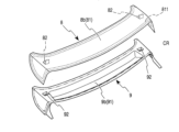
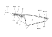
以下、本発明に係る車両用スポイラ(以下、単に「スポイラ」ともいう。)について詳述する。図1~図11は本発明のスポイラの一形態で、図1はロア部材の斜視図、図2はアッパー部材の斜視図、図3はロア部材とアッパー部材を重ね合わせた斜視図、図4は図3の部分拡大図、図5は板片状体と立板片との隙間に接着剤の固化部を形成したスポイラの説明横断面図、図6は図5の部分拡大図、図7,図8は図5の板片状体と立板片周りにおけるスポイラを製造する各工程断面図、図9は図6に代わる他態様図を示す。尚、各図は判り易くするため、簡略化し且つ発明要部を強調図示する。 The vehicle spoiler (hereinafter, simply referred to as "spoiler") according to the present invention will be described in detail below. Figures 1 to 11 show one embodiment of the spoiler of the present invention, with Figure 1 being a perspective view of the lower member, Figure 2 being a perspective view of the upper member, Figure 3 being a perspective view of the lower member and the upper member superimposed, Figure 4 being a partial enlargement of Figure 3, Figure 5 being an explanatory cross-sectional view of a spoiler in which a solidified portion of adhesive is formed in the gap between the plate-shaped body and the standing plate, Figure 6 being a partial enlargement of Figure 5, Figures 7 and 8 being cross-sectional views of each process of manufacturing the spoiler around the plate-shaped body and the standing plate in Figure 5, and Figure 9 being a view of another embodiment in place of Figure 6. Note that each figure is simplified and the essential parts of the invention are emphasized for ease of understanding.
(1)車両用スポイラ 車両用スポイラは、立板片22を有する合成樹脂製アッパー部材2と、スリット30と板片状体32を有する合成樹脂製ロア部材3と、を具備し、双方の外周部分211,311を接着剤4で貼り合せて一体化したものである。図5のような自動車7で、ワゴンタイプのルーフエンド71近くのバックドアに、紙面垂直方向の車幅方向に延びる翼状の本スポイラ1が取付けられる。符号215,315がアッパー部材2,ロア部材3の車両前方側の外周縁になる。
(1) Vehicle spoiler The vehicle spoiler comprises a synthetic resin
アッパー部材2は、車幅方向に長いスポイラ1の上半部を形成する平板状の射出成形品である(図2)。車幅方向に長く伸びた本体21の両サイドは下方へ屈曲し、ガード部を形成する。アッパー部材2は、図5の車両取付け状態で、上面が意匠面になる略平坦な表面21aを形成する本体21と、該本体21の内面21bに起立形成された立板片22と、を備える。
The
立板片22は、アッパー部材2とロア部材3との重ね合わせでロア部材3のスリット30を通って、車両取付け状態でロア部材3の下面側、すなわち外面31a側へ突き出るように、アッパー部材本体21に立設するリブ状の突片である(図6)。 本実施形態の立板片22は、アッパー部材2の射出成形本体21から延在形成された射出成形部分になっている。車両前方寄りの設置スペースを確保できる箇所で、アッパー部材2の車幅方向両サイド近くの本体内面21bに、立板片22を一対設ける。ここでは、従来技術の図11に示す機械締結用の受片部82,板片部92,ビスVをなしにして、空いた空間に立板片22を設ける。図2のような方形の立板片22が、その基端周りの本体内面21bに対して略垂直起立する。前記ガード部を除いたアッパー部材本体21で、接着剤4が塗布される外周部分211の帯状主要面に対しても、立板片22が略垂直起立するよう設定される。立板片22に係る板片幅Wの幅方向に関しては車幅方向に合わせているが、これに限らず車両前後方向等でもよい。立板片22は、頂部221の部位で、頂面22fに近づくにつれ板片幅Wを小さくし、スリット30への立板片22の挿入を容易にしている。 立板片22の数は、そのスペース確保ができれば、多く設ける方が好ましい。立板片22は、板面22dに接着剤4が塗布されて、次に述べるロア部材3の板片状体32との接着一体化を強力にするため、板面22dの大きいものがより好ましい。
The standing
ロア部材3は、前記アッパー部材2と一体化される二枚合わせスポイラ1の下半部で、図1のごとく車幅方向に長い射出成形品である。ロア部材3は、その外周縁315,316よりもアッパー部材2の外周縁215,216の方を少し大きめにして、これに被われる図5のような横断面形状になっている。ロア部材3のメイン部たる主部31に、凹んだ格納壁部分312を形成する。ロア部材3とアッパー部材2が接着剤4で貼り合せて一体化されたとき、アッパー部材2で該格納壁部分312の開口側を被って、アンテナ等を格納する中空部Sが形成される。 このロア部材3には、スポイラ下部本体を形成する主部31に、スリット30と板片状体32とが設けられる。
The
スリット30は、アッパー部材2とロア部材3の接着一体化に伴い、立板片22がロア部材3の外面側、詳しくは主部31の外面31a側へ突き出るよう、該立板片22に対応するロア部材主部31に形成された細長孔である。該スリット30は、立板片22の最大横断面形状に合せた大きさにして、該立板片22の根元が嵌合する大きさにする。立板片22を該スリット30に挿入し、アッパー部材2とロア部材3とが接着剤4を介して重なり合って一体化できるよう、該立板片22の横断面形状に合わせた図1ごとくの縦長矩形孔のスリット30になっている。スリット30は、本体内面21bに起立した立板片22と対向するロア部材主部31の、車幅方向両サイド近くに設けられる。ロア部材3には該スリット30に沿って板片状体32が設けられる。
The
板片状体32は、前記スリット30に係る長手方向の孔縁301沿いに設けられ、前
記ロア部材3の主部外面31aにリブ状に起立形成された突出片である(図1)。板片状体32が、スリット30の長手方向の孔縁301に沿って設けられるとは、図7のように板片状体32の基端321がスリット30の孔縁301に一致するのは勿論、図1,図4のごとく長手方向の孔縁301から僅かに離れた位置に設けられるのも含む。板片状体32は、ロア部材3の射出成形主部31から延在形成された射出成形部分になっている。アッパー部材2とロア部材3との接着一体化に伴い、ロア部材3の外面31a側へ突き出る前記立板片22の板面22dと、板片状体32の板面32dとが対向し近接する状態にして、該板片状体32が主部外面31aに立設する。板片状体32の板面32dは、立板片22との接着面積ができるだけ大きくなるよう、立板片22の板面22dと略同形状とする。 スリット30に係る長手方向の一方の孔縁301沿いに一の板片状体32を立設するだけでもよいが、本実施形態は、スリット30に係る長手方向の両孔縁301,301沿いのロア部材主部31に、板片状体32をそれぞれ形成している。両板片状体32は、立板片22をスリット30に円滑挿入させて、該立板片22の起立安定を保つ位置決めリブにもなる。両板片状体32のそれぞれが立板片22と隙間εを形成し、両隙間εに接着剤4の固化部4Bが埋まる。
The plate-piece-
接着剤4の固化部4Bは、板片状体32と立板片22との両対向板面22d,32d間の隙間εに充填され、双方を接着一体化している接着剤4の硬化部である。スリット30に挿通した立板片22の板面22dに対し、板面32dを対向させ近接する板片状体32がロア部材主部31に起立している。よって、図3のようにアッパー部材2とロア部材3を合わせると、立板片22と板片状体32間に図4ごとくの隙間εができる。アッパー部材2とロア部材3で一体化した二枚合わせの本スポイラ1では、該隙間εに、立板片22と板片状体32とを一体化する接着剤4の固化部4Bが詰まっている(図6)。
The solidified
ここで、隙間εを埋める接着剤4の厚みは薄いが、接着強さの面からいえば、接着剤固化部4Bの層は連続している限り薄い方が好適とされ、良好な接着剤固化部4Bを形成する。しかも、本実施形態の固化部4Bは、図6のごとく立板片22の両板面22d,22dに形成される。立板片22の両板面22d,22dと、スリット30に係る長手方向の両孔縁301沿いに形成した板片状体32の対向板面32d間の二つの隙間εにそれぞれ充填される固化部4B2が在るスポイラ1になっている。 また、板片状体32と立板片22との両対向板面22d,32d間の隙間εに充填した接着剤4の固化部4B2は、該両対向板面22d,32dの先端322を越えて板片状体32の頂面32f上及び該立板片22の頂面22f上にまで連続形成される。板片状体32及び該立板片22の頂面22f,32f上の固化部4B3が、アッパー部材2とロア部材3の剥がれ防止に役立つ。
Here, the thickness of the adhesive 4 filling the gap ε is thin, but in terms of adhesive strength, it is preferable that the layer of the adhesive solidified
接着剤4の固化部4Bに関しては、隙間εだけに限らず、従来のスポイラ1と同様、アッパー部材2とロア部材3の外周部分211,311を接着剤4で貼り合せて、図5のごとく両者を一体化する接着剤4の固化部4Bも形成される。ロア部材内面31bの外周縁315,316を外縁にした帯状の外周部分311と、これに対応するアッパー部材内面21bの部位の外周部分211とに、接着剤4が挟着されて硬化し、固化部4B1となっている。該固化部4B1は、図1,図2のような外周部分211,311上に周回形成されるのが望ましいが、意匠面形状の制限等により断続形成されていてもよい。
The solidified
ちなみに、ここで用いた接着剤4は一液湿気硬化型のウレタン接着剤4である。本スポイラ用接着剤4の特性としては、一液型でなくてもよいが、分子量が高く粘性の高いものが好ましい。具体的には30,000~1,000,000mPa・sの範囲のものがより好ましい。起立する立板片22の板面22dに低粘度の接着剤4を塗布すると、すぐに流れ落ち拡がってしまうが、接着剤4が高粘性であるため、隙間εを埋める該接着剤4が板面22d及びその付近にとどまり易い。加えて、立板片22に接着剤4を塗布して30秒程度で接着剤4の初期圧着硬化を完了させることができ、後述する圧治具Tから取り出した後のスポイラ1の、ハンドリングがし易くなる。隙間εに接着剤4の固化部4Bをスピーディに形成でき、生産性向上にも貢献する所望のスポイラ1になっている。
The adhesive 4 used here is a one-component moisture-curing
さらに、本実施形態のスポイラ1は、図4,図7のように板片状体32の前記孔縁301側とは反対側の基端321周りに在る前記主部31に、板厚を貫通する開口33を設けている。且つその内面側開口33bよりも外面側開口33aの方を大きく形成する。該外面側開口33aを含む開口33内に図6のように接着剤4の固化部4B4を充填形成して、アンカーにする。該固化部4B4がアッパー部材2とロア部材3の剥がれ防止用ストッパになる。図8(ニ)のごとく、開口33の該固化部4B4は、内面側開口33b周りのロア部材主部31とこれに対向するアッパー部材本体21とに挟着された固化部4Bとにつながっているので、ストッパとしてより有効に働く。 また、図9に、スリット30の一孔縁301にのみ板片状体32が起立する他態様のスポイラ1を示す。立板片22の頂部221に係る板厚tを、頂面22fに向けて徐々に小さくして、斜面2211を形成する。該斜面2211を含む頂面22f周りに接着剤4の固化部4B3を設けることで、アッパー部材2とロア部材3の更なる剥がれ防止に役立つようにしている。 符号22eは立板片22の板厚面、符号32eは板片状体32の板厚面、符号302はスリット30の短手方向の孔縁、符号39は相手部材への取付板部分、符号CRは屈曲ラインを示す。尚、本発明はアッパー部材2,ロア部材3を、アウター部材,インナー部材に置換えることができる。同様の作用,効果を得るからである。 斯かるスポイラ1は、例えば次に述べる車両用スポイラの製造方法によって造ることができる。
Furthermore, in the
(2)車両用スポイラの製造方法 車両用スポイラの製造方法は、アッパー部材2とロア部材3の双方内面21b,31bの外周部分211,311を接着剤4で貼り合せて一体化すると共に、立板片22と板片状体32との隙間εに充填した接着剤4を硬化させて両者を一体化する製法である。 アッパー部材2は本体内面21bに立板片22を起立形成し、前記一体化に伴い、該立板片22がロア部材3の外面側へ突き出るよう、立板片22に対応するロア部材3の主部31にスリット30を設ける。またロア部材3は、該スリット30に係る長手方向の孔縁301沿いの主部外面31aに、前記一体化に伴う立板片22の板面22dと板面32dとが対向して近接する板片状体32を起立形成している。 図5のようなスポイラ1は、図1のロア部材3,図2のアッパー部材2,接着剤4,圧着治具Tを準備して、例えば次のようにして造られる。
(2) Manufacturing method of vehicle spoiler The manufacturing method of the vehicle spoiler is a manufacturing method in which the outer
まず、アッパー部材内面21bとロア部材内面31bが向き合うよう、アッパー部材用治具の下治具5にアッパー部材2をセットすると共に、ロア部材用治具の上治具6にロア部材3をセットする。アッパー部材2を本体用受け面51で支え、ロア部材3を主部用受け面61で支える。主部用受け面61には、二つの板片状体32が収められる凹所62と、前記開口33用の囲い部63とが形成されている。 次に、双方の外周部分211,311又は一方の外周部分211(又は311)に接着剤4を塗布すると共に、立板片22の板面22dに接着剤4を塗布する。ここでは、アッパー部材2の外周部分211にのみ接着剤4を塗布し、また立板片22周りの本体内面21b上を含めて、該立板片22の全面を覆うように接着剤4を塗布する。そして、立板片22がスリット30と対向する図7(イ)の状態とする。
First, the
続いて、圧着工程に移る。ロア部材3をセットした上治具6を、図7(ロ)の白抜矢印のごとく下降させ、立板片22をスリット30に挿入する。同図の立板片22を覆う接着剤4の粘り気のある糊状ペースト4Aが、該立板片22と共に凹所62内へ入り込み、また内面側開口33bから開口33内にも入り込む。
Then, we move to the crimping process. The
さらに、上治具6を図8(ハ)の白抜矢印のごとく下降させ、接着剤4を介してアッパー部材2とロア部材3とを、圧着治具で圧着する同図の状態にする。スリット30に挿通した立板片22は主部31の外面31a側へ突き出て、該立板片22の両板面22d,22dに各板片状体32の板面32dが隙間εを介して対向する。そして、立板片22を覆っていた接着剤4が該隙間εを埋める。該接着剤4は、図7(ロ)~図8のごとく対向板面22d,32dの先端322を越えて、該板片状体32の頂面32f上及び該立板片22の頂面22f上にある余剰空間621をも埋める。ここでは、上治具6へのロア部材3のセットで、板片状体頂面32f及び立板片頂面22fと凹所62の底面との間に余剰空間621を設けている。スリット30への挿通を終え、立板片22の主部外面31a側へ突き出し完了した図8(ハ)の状態で、該余剰空間621が接着剤4で埋まる形になっている。 また、該立板片22の突き出し完了と並行して、本体内面21bの外周部分211に塗布した接着剤4で、該外周部分211と主部内面31bの外周部分311とが貼り合わさる。
Furthermore, the
しかる後、図8(ハ)の状態を所定時間保ち、接着剤4を硬化させる。アッパー部材2,ロア部材3の外周部分211,311で挟まれた接着剤4と、立板片22の板面22dへの接着剤4の塗布により両対向板面22d,32d間の隙間εを埋め充填された接着剤4とを、硬化させて固化部4Bを形成する。頂面22f,32f上の固化部4B3,開口33の固化部4B4も形成する。 その後、上治具6を図8(ニ)の白抜矢印のごとく上昇させる。下治具5上に固化部4Bによるアッパー部材2とロア部材3との一体品が現れ、これを取り出し、所望のスポイラ1を得る。
Then, the state shown in FIG. 8(c) is maintained for a predetermined time to harden the adhesive 4. The adhesive 4 sandwiched between the outer
板片状体32は、立板片22の一方の板面22d側に設けるだけでもよいが、本実施形態はスリット30に係る長手方向の両孔縁301沿いのロア部材3にそれぞれ設けている。立板片22の両板面22d,22dに各板片状体32の板面32dが隙間εを介して対向する。立板片22の両板面22d,22dに接着剤4を塗布した後、スリット30に挿通させた立板片22を主部31の外面側へ突き出し、立板片22の両板面22d,22dと二つ在る板片状体32のそれぞれの対向板面32dとの各隙間εに充填された接着剤4を硬化させて固化部4Bを形成する。立板片22の両板面22d,22dに固化部4Bを設けることによって、片方の板面22dだけに比べ、接着面を倍増させた所望のスポイラ1が得られる。 符号35は必要に応じて設ける接着剤4の流れ防止堰、符号69は離型コーティングを示す。他の構成は(1)の車両用スポイラで述べたものと同様で、その説明を省略する。(1)と同一符号は、同一又は相当部分を示す。
The plate-shaped
(3)効果 このように構成した車両用スポイラは、アッパー部材2とロア部材3との貼り合せ強度を効果的に高め、スポイラ製品の品質向上,信頼性向上を図り、優れた効果を発揮する。 第1の発明のごとく、本体内面21bに起立する立板片22と、立板片22に対応する主部31に設けたスリット30と、アッパー部材2とロア部材3の一体化によって立板片22の板面22dに板面32dが近接して、主部外面31aに起立する板片状体32と、両対向板面22d,32d間の隙間εに充填し接着一体化する接着剤4の固化部4Bと、を具備すると、スポイラ1の意匠形状によって接着剤4の平面確保が難しいケースでも、新たな接着剤用平面を容易に確保できる。スポイラ1の意匠面形状に自由度を与える。本体内面21bが多少でこぼこしていても、そこに立板片22を起立させて、該立板片22と板片状体32の平面状両板面22d,32dを接着一体化させることができる。貼り合せ面の外周部分211,311が平面でなくても、立板片22,板状片32の設定ができるため、スポイラ1の形状自由度が上がる。立板片22と板片状体32を設ける空間確保さえできれば、スポイラ1の意匠形状に制限されない。立板片22と板片状体32を形成するだけで、容易に接着面を追加増大させて貼り合せ強度を高めることができる。
(3) Effect The vehicle spoiler thus constructed effectively increases the bonding strength between the
また、アッパー部材2の本体内面21bに起立形成された立板片22とロア部材3の板片状体32との隙間εに接着剤4の固化部4Bを形成すると、双方を接着一体化する接着面が、外周部分211,311での接着面と角度を大きく変えるので、接着剤4の特性を生かして貼り合せ強度を格段に高める。 アッパー部材本体21に起立する立板片22とロア部材主部31に起立する板片状体32とを接着一体化している接着剤固化部4Bの接着面は、アッパー部材内面21bの外周部分211とロア部材内面31bの外周部分311を一体化している接着剤固化部4Bの主要接着面に対して、図6のように略直交する形になっている。 接着剤4の強さとして剪断強さと剥離強さがあるが、通常、一方の強さを大きくすると他方の強さが低下する性質をもつ(新保正樹:接着強さと破壊,「接着ハンドブック第2版」,54頁,日刊工業新聞社(1991))。例えば剪断強さを大きく設定した接着剤4を用いた場合、外周部分211,311を一体化している接着剤固化部4B1は剥離強さが低下しており、ロア部材3からアッパー部材2が図6の上方へ剥がれ易くなる。しかし、外周部分211,311を一体化している接着剤固化部4B1の接着面に対し、垂直に近い角度で交差する隙間充填固化部4B2の接着面が存在することで、先に剪断強さを大きく設定していた接着剤4の剪断力が有効に働き、その威力を発揮する。ロア部材3からアッパー部材2が図6の上方へ剥がれようとするのを、隙間充填固化部4B2の剪断力が強力に働き、阻止できる。ロア部材3からアッパー部材2が図6の上方へ剥がすのに要する外力を大幅アップさせることになる。剪断強さと剥離強さを逆にした接着剤4を用いる場合は、外周部分の固化部4B1に係る接着面の剥離強さに加え、更に該接着面に交差する隙間充填固化部4B2に係る接着面の剪断強さで効果的に増強補完でき、極めて理にかなったスポイラ1になっている。
In addition, when solidified
さらに、アッパー部材2の立板片22がロア部材3に設けたスリット30を突き出る構成であるので、接着剤固化部4B1の接着面の剪断力が弱くて、ロア部材3からアッパー部材2が横ずれで外れようとすると、スリット30の孔縁301,302周りのロア部材主部31、及び板片状体32が立板片22の動きを止める。アッパー部材2の横ずれを阻止できる。ロア部材3に対しアッパー部材2が剪断方向に外れ難い構造になっている。 さらにいえば、立板片22を、スリット30に挿通し主部31の外面31a側へ突き出して、アッパー部材2とロア部材3とを貼り合せて一体化する構成であるので、立板片22をスリット30に挿通すれば、アッパー部材2がロア部材3に対し自律的に位置決めされるので、両者を一体化する二枚合わせ作業が極めて容易になっている。位置ズレの心配がない。
Furthermore, since the standing
上述のごとく、アッパー部材本体21に起立する立板片22と、ロア部材主部31に起立する板片状体32と、両板面22d,32d間に隙間充填固化部4B2とを設けるので、本発明が単に接着剤4の接着面を増やすにとどまらず、該隙間充填固化部4B2の接着一体化が接着剤4の特性を生かして、ロア部材3とアッパー部材2の一体化維持に大きく貢献する。 立板片22,板片状体32によって貼り合せ強度を高くでき、機械締結代替えの可能性がある。機械締結による歪みをなくし低コスト化につながる。
As described above, the
第2の発明のごとく、立板片22がアッパー部材2の射出成形本体21から延在形成された射出成形部分であり、且つ板片状体32がロア部材3の射出成形主部31から延在形成された射出成形部分であると、低コスト化できる。 第3の発明のごとく、スリット30に係る長手方向の両孔縁301沿いのロア部材3に、板片状体32がそれぞれ形成されると、立板片22の両方の板面22d,22dに板片状体32と一体化する接着剤4の隙間充填固化部4B2を設けることができる。板片状体32を一枚増やす小スペース確保だけで、隙間充填固化部4B2の接着面を倍増でき、接着力を効果的に増大できる。 加えて、スリット30の両孔縁301沿いに一対の板片状体32が起立すると、スリット30に挿通し主部外面31aに突き出る立板片22を位置決め保持するので、アッパー部材2とロア部材3の貼り合せ時にずれたりぐらついたりせず、作業性向上,品質安定させる。
As in the second invention , if the standing
第4の発明のごとく、板片状体32の孔縁301側とは反対側の基端321周りに在る主部31に板厚を貫通する開口33が設けられ、且つその内面側開口33bよりも外面側開口33aの方を大きくすると、例えば隙間充填固化部4B2から外面側開口33a上に連なる開口33に固化部4B4を充填することによって、該固化部4B4をアッパー部材2とロア部材3の剥がれ防止用ストッパにできる。 第5の発明のごとく、板片状体32と立板片22との両対向板面22d,32d間の隙間εを充填した接着剤4の固化部4B2が、該両対向板面22d,32dの先端322を越えて該板片状体32の頂面32f上及び該立板片22の頂面22f上にまで連続して設けられると、頂面22f,32f上の固化部4B3はアッパー部材2とロア部材3とが剥がれる際にこれを阻止する抵抗部分になる。アッパー部材2とロア部材3との一体化維持に効を奏する。
As in the fourth invention , when an
第6の発明のごとく、立板片頂部221の部位で、頂面22fに近づくにつれ立板片22の板片幅Wを小さくすると、スリット30への立板片22の挿入が楽になる。 第7の発明のごとく、立板片22の頂部221に係る板厚tを、頂面22fに向けて徐々に小さくすると、該頂面22fに向けて小さくなる傾斜面2211上に固化部4Bを設けることによって、該固化部4Bをアッパー部材2とロア部材3の剥がれ防止用ストッパにできる。 かくのごとく、本車両用スポイラは、上述した種々の優れた効果を発揮し、極めて有益である。
As in the sixth invention , if the plate width W of the standing
尚、本発明は前記実施形態に示すものに限られず、目的,用途に応じて本発明の範囲で種々変更できる。アッパー部材2,立板片22,ロア部材3,スリット30,板片状体32,接着剤4,圧着治具T等の形状,大きさ,個数,材質等は用途に合わせて適宜選択できる。例えば実施形態の板片状体33は、立板片22の板面22dと対向する板面33dが平面であれば足り、反対面側は蒲鉾状の凸形になる板片状体33でもよい。
The present invention is not limited to the above embodiment, and can be modified in various ways within the scope of the present invention depending on the purpose and application. The shape, size, number, material, etc. of the
1 スポイラ 2 アッパー部材 22 本体(アッパー部材本体) 21b 本体内面(アッパー部材内面) 211 本体の外周部分 22 立板片 22d 板面 3 ロア部材 30 スリット 31 主部(ロア部材主部) 31b 主部内面(ロア部材内面) 311 主部の外周部分 32 板片状体 32d 板面 33 開口 4 接着剤 4B 固化部 4B1 外周部分の固化部(固化部) 4B2 隙間充填固化部(固化部) ε 隙間
1
Claims (4)
前記外周部分以外の箇所において、
前記第1部材に起立形成された立板片と、
前記第2部材に起立形成された板片状体と、
前記立板片と前記板片状体との間に充填された湿気硬化型接着剤の固化部と、を具備することを特徴とする車両用スポイラ。 A synthetic resin vehicle spoiler in which outer peripheral portions of a first member and a second member are bonded together with an adhesive to form an integrated body,
At a location other than the outer circumferential portion,
A standing plate piece formed upright on the first member;
A plate-shaped body formed upright on the second member;
a solidified portion of a moisture-curing adhesive filled between the upright plate piece and the plate-shaped body.
前記第1部材に起立形成された立板片と、
前記第2部材に起立形成された一対の板片状体と、
前記立板片と各板片状体の間に充填された前記湿気硬化型接着剤の固化部と、を具備し、
前記固化部が前記各板片状体の頂面と前記第1部材との間の空間を埋めていることを特徴とする車両用スポイラ。 A synthetic resin vehicle spoiler in which a first member and a second member are bonded together with a moisture-curing adhesive,
A standing plate piece formed upright on the first member;
A pair of plate-shaped bodies formed upright on the second member;
A solidified portion of the moisture-curing adhesive filled between the standing plate and each plate-shaped body ,
A vehicle spoiler, characterized in that the solidified portion fills a space between a top surface of each of the plate-shaped bodies and the first member .
前記第1部材に起立形成された立板片と、
前記第2部材に起立形成された板片状体と、
前記立板片と前記板片状体の間に充填された前記湿気硬化型接着剤の固化部と、を具備し、
前記固化部が前記立板片及び前記板片状体の頂面上にまで連続して設けられ、該頂面上
に設けられた固化部が外部に露出していることを特徴とする車両用スポイラ。 A synthetic resin vehicle spoiler in which a first member and a second member are bonded together with a moisture-curing adhesive,
A standing plate piece formed upright on the first member;
A plate-shaped body formed upright on the second member;
A solidified portion of the moisture-curing adhesive filled between the upright plate piece and the plate-shaped body ,
The solidification portion is provided continuously on the top surfaces of the upright plate and the plate-like body,
A vehicle spoiler, characterized in that a solidified portion provided on the vehicle spoiler is exposed to the outside .
に設けられた固化部が外部に露出している請求項1又は2に記載の車両用スポイラ。 3. The vehicle spoiler according to claim 1, wherein the solidified portion is provided continuously onto the top surfaces of the upright plate piece and the plate-shaped body, and the solidified portion provided on the top surfaces is exposed to the outside.
Priority Applications (1)
| Application Number | Priority Date | Filing Date | Title |
|---|---|---|---|
| JP2023190670A JP7588198B2 (en) | 2020-01-14 | 2023-11-08 | Vehicle spoiler |
Applications Claiming Priority (2)
| Application Number | Priority Date | Filing Date | Title |
|---|---|---|---|
| JP2020003541A JP7383499B2 (en) | 2020-01-14 | 2020-01-14 | vehicle spoiler |
| JP2023190670A JP7588198B2 (en) | 2020-01-14 | 2023-11-08 | Vehicle spoiler |
Related Parent Applications (1)
| Application Number | Title | Priority Date | Filing Date |
|---|---|---|---|
| JP2020003541A Division JP7383499B2 (en) | 2020-01-14 | 2020-01-14 | vehicle spoiler |
Publications (2)
| Publication Number | Publication Date |
|---|---|
| JP2024020316A JP2024020316A (en) | 2024-02-14 |
| JP7588198B2 true JP7588198B2 (en) | 2024-11-21 |
Family
ID=77058882
Family Applications (2)
| Application Number | Title | Priority Date | Filing Date |
|---|---|---|---|
| JP2020003541A Active JP7383499B2 (en) | 2020-01-14 | 2020-01-14 | vehicle spoiler |
| JP2023190670A Active JP7588198B2 (en) | 2020-01-14 | 2023-11-08 | Vehicle spoiler |
Family Applications Before (1)
| Application Number | Title | Priority Date | Filing Date |
|---|---|---|---|
| JP2020003541A Active JP7383499B2 (en) | 2020-01-14 | 2020-01-14 | vehicle spoiler |
Country Status (1)
| Country | Link |
|---|---|
| JP (2) | JP7383499B2 (en) |
Families Citing this family (1)
| Publication number | Priority date | Publication date | Assignee | Title |
|---|---|---|---|---|
| KR20240040211A (en) * | 2022-09-21 | 2024-03-28 | 현대자동차주식회사 | Vehicle spoiler and manufacturing method thereof |
Citations (3)
| Publication number | Priority date | Publication date | Assignee | Title |
|---|---|---|---|---|
| JP2014091442A (en) | 2012-11-05 | 2014-05-19 | Kasai Kogyo Co Ltd | Interior material for vehicle |
| JP2015030306A (en) | 2013-07-31 | 2015-02-16 | ダイキョーニシカワ株式会社 | Vehicle back door assembly structure |
| JP2019044005A (en) | 2017-08-30 | 2019-03-22 | Dic株式会社 | Moisture-curable hot melt adhesive and laminate |
Family Cites Families (7)
| Publication number | Priority date | Publication date | Assignee | Title |
|---|---|---|---|---|
| JPS5725345A (en) * | 1980-07-23 | 1982-02-10 | Asahi Chem Ind Co Ltd | Molded product for exterior automative trim and attachment thereof |
| JPH0245888U (en) * | 1988-09-26 | 1990-03-29 | ||
| JPH0249680U (en) * | 1988-09-30 | 1990-04-06 | ||
| JPH0686228B2 (en) * | 1989-01-30 | 1994-11-02 | 本田技研工業株式会社 | Rear spoiler for vehicle |
| JPH08150963A (en) * | 1994-11-30 | 1996-06-11 | Nissan Motor Co Ltd | Hollow molded product |
| JP5551572B2 (en) | 2010-11-25 | 2014-07-16 | 株式会社イノアックコーポレーション | Spoiler |
| JP2013067319A (en) | 2011-09-26 | 2013-04-18 | Inoac Corp | On-vehicle spoiler and its mounting structure |
-
2020
- 2020-01-14 JP JP2020003541A patent/JP7383499B2/en active Active
-
2023
- 2023-11-08 JP JP2023190670A patent/JP7588198B2/en active Active
Patent Citations (3)
| Publication number | Priority date | Publication date | Assignee | Title |
|---|---|---|---|---|
| JP2014091442A (en) | 2012-11-05 | 2014-05-19 | Kasai Kogyo Co Ltd | Interior material for vehicle |
| JP2015030306A (en) | 2013-07-31 | 2015-02-16 | ダイキョーニシカワ株式会社 | Vehicle back door assembly structure |
| JP2019044005A (en) | 2017-08-30 | 2019-03-22 | Dic株式会社 | Moisture-curable hot melt adhesive and laminate |
Also Published As
| Publication number | Publication date |
|---|---|
| JP2024020316A (en) | 2024-02-14 |
| JP2021109580A (en) | 2021-08-02 |
| JP7383499B2 (en) | 2023-11-20 |
Similar Documents
| Publication | Publication Date | Title |
|---|---|---|
| US20050257362A1 (en) | Procede de fabrication d'une piece de carrosserie de vehicule automobile, piece de carrosserie | |
| US8132386B2 (en) | Use of a window glass comprising a profiled bead for installing it in an opening | |
| US7083212B2 (en) | Applique for A-pillar area of vehicle | |
| US20110266716A1 (en) | Sealing Molding With Insert For Forming Closeout Surface | |
| US20200307708A1 (en) | Vehicle Structural Component and Method for Producing a Vehicle Structural Component | |
| US10040227B2 (en) | Method for manufacturing a vehicle interior trim part intended for covering an airbag | |
| JPH10196620A (en) | Connecting method by which one component is connected to another component | |
| JP2024020316A (en) | vehicle spoiler | |
| US20180304822A1 (en) | Trim part with integrated antenna | |
| KR20090122427A (en) | A method of assembling the glass onto its holder by gluing, and means for implementing the method | |
| ES2303031T5 (en) | Manufacturing procedure of a car vehicle structure part, structure part, technical front face crossbar and bumper beam | |
| JP6800068B2 (en) | Vehicle backdoor and its manufacturing method | |
| JP7426834B2 (en) | Manufacturing method of vehicle spoiler | |
| US20030168890A1 (en) | Car body part and method of its production | |
| JP2001515422A (en) | Method of forming a bond between a member and a component | |
| JPH1053026A (en) | Mounting structure of automobile weather strip | |
| JP3861535B2 (en) | Fixing structure and fixing method of resin outer plate in automobile body | |
| JPH1178540A (en) | Weather strip | |
| JP6164677B2 (en) | Method of manufacturing ceiling interior member with duct | |
| JPS60219181A (en) | Fixing of quarter window glass | |
| JP3366547B2 (en) | Joint structure of partition sash | |
| US20070012400A1 (en) | Bonding method | |
| JPH0436967Y2 (en) | ||
| JPH05155271A (en) | Vehicular interior panel | |
| JPH03112720A (en) | Window mold |
Legal Events
| Date | Code | Title | Description |
|---|---|---|---|
| A521 | Request for written amendment filed |
Free format text: JAPANESE INTERMEDIATE CODE: A523 Effective date: 20231108 |
|
| A621 | Written request for application examination |
Free format text: JAPANESE INTERMEDIATE CODE: A621 Effective date: 20231108 |
|
| A977 | Report on retrieval |
Free format text: JAPANESE INTERMEDIATE CODE: A971007 Effective date: 20240510 |
|
| A131 | Notification of reasons for refusal |
Free format text: JAPANESE INTERMEDIATE CODE: A131 Effective date: 20240528 |
|
| A521 | Request for written amendment filed |
Free format text: JAPANESE INTERMEDIATE CODE: A523 Effective date: 20240723 |
|
| TRDD | Decision of grant or rejection written | ||
| A01 | Written decision to grant a patent or to grant a registration (utility model) |
Free format text: JAPANESE INTERMEDIATE CODE: A01 Effective date: 20241105 |
|
| A61 | First payment of annual fees (during grant procedure) |
Free format text: JAPANESE INTERMEDIATE CODE: A61 Effective date: 20241111 |
|
| R150 | Certificate of patent or registration of utility model |
Ref document number: 7588198 Country of ref document: JP Free format text: JAPANESE INTERMEDIATE CODE: R150 |