JP7586840B2 - Vacuum gripper for warped workpieces - Google Patents
Vacuum gripper for warped workpieces Download PDFInfo
- Publication number
- JP7586840B2 JP7586840B2 JP2021567842A JP2021567842A JP7586840B2 JP 7586840 B2 JP7586840 B2 JP 7586840B2 JP 2021567842 A JP2021567842 A JP 2021567842A JP 2021567842 A JP2021567842 A JP 2021567842A JP 7586840 B2 JP7586840 B2 JP 7586840B2
- Authority
- JP
- Japan
- Prior art keywords
- gripper
- suction
- opening
- workpiece
- openings
- Prior art date
- Legal status (The legal status is an assumption and is not a legal conclusion. Google has not performed a legal analysis and makes no representation as to the accuracy of the status listed.)
- Active
Links
Images


Classifications
-
- H10P72/78—
-
- B—PERFORMING OPERATIONS; TRANSPORTING
- B25—HAND TOOLS; PORTABLE POWER-DRIVEN TOOLS; MANIPULATORS
- B25J—MANIPULATORS; CHAMBERS PROVIDED WITH MANIPULATION DEVICES
- B25J11/00—Manipulators not otherwise provided for
- B25J11/0095—Manipulators transporting wafers
-
- B—PERFORMING OPERATIONS; TRANSPORTING
- B25—HAND TOOLS; PORTABLE POWER-DRIVEN TOOLS; MANIPULATORS
- B25J—MANIPULATORS; CHAMBERS PROVIDED WITH MANIPULATION DEVICES
- B25J15/00—Gripping heads and other end effectors
- B25J15/0014—Gripping heads and other end effectors having fork, comb or plate shaped means for engaging the lower surface on a object to be transported
-
- B—PERFORMING OPERATIONS; TRANSPORTING
- B25—HAND TOOLS; PORTABLE POWER-DRIVEN TOOLS; MANIPULATORS
- B25J—MANIPULATORS; CHAMBERS PROVIDED WITH MANIPULATION DEVICES
- B25J15/00—Gripping heads and other end effectors
- B25J15/0052—Gripping heads and other end effectors multiple gripper units or multiple end effectors
- B25J15/0061—Gripping heads and other end effectors multiple gripper units or multiple end effectors mounted on a modular gripping structure
-
- B—PERFORMING OPERATIONS; TRANSPORTING
- B25—HAND TOOLS; PORTABLE POWER-DRIVEN TOOLS; MANIPULATORS
- B25J—MANIPULATORS; CHAMBERS PROVIDED WITH MANIPULATION DEVICES
- B25J15/00—Gripping heads and other end effectors
- B25J15/06—Gripping heads and other end effectors with vacuum or magnetic holding means
- B25J15/0616—Gripping heads and other end effectors with vacuum or magnetic holding means with vacuum
- B25J15/0625—Gripping heads and other end effectors with vacuum or magnetic holding means with vacuum provided with a valve
-
- B—PERFORMING OPERATIONS; TRANSPORTING
- B25—HAND TOOLS; PORTABLE POWER-DRIVEN TOOLS; MANIPULATORS
- B25J—MANIPULATORS; CHAMBERS PROVIDED WITH MANIPULATION DEVICES
- B25J15/00—Gripping heads and other end effectors
- B25J15/06—Gripping heads and other end effectors with vacuum or magnetic holding means
- B25J15/0616—Gripping heads and other end effectors with vacuum or magnetic holding means with vacuum
- B25J15/0683—Details of suction cup structure, e.g. grooves or ridges
-
- H10P72/7602—
Landscapes
- Engineering & Computer Science (AREA)
- Robotics (AREA)
- Mechanical Engineering (AREA)
- Manipulator (AREA)
- Physics & Mathematics (AREA)
- Condensed Matter Physics & Semiconductors (AREA)
- General Physics & Mathematics (AREA)
- Manufacturing & Machinery (AREA)
- Computer Hardware Design (AREA)
- Microelectronics & Electronic Packaging (AREA)
- Power Engineering (AREA)
- Container, Conveyance, Adherence, Positioning, Of Wafer (AREA)
Description
本発明は、ウェハ処理に関する。より詳細には、本発明は、反ったワークピースを把持するように適合された吸着グリッパに関する。 The present invention relates to wafer processing. More particularly, the present invention relates to a suction gripper adapted to grip a warped workpiece.
多くの用途では、平らで薄いワークピースの把持および操作が必要である。例えば、集積回路や他の電子部品などの半導体デバイスの製造では、典型的にウェハの形をした半導体基板を、基板に処理工程を適用するために、または基板を検査するために、操作しなければならない。基板を把持するアームは、基板を処理または検査のために必要な位置に搬送するように操作され得る。 Many applications require the gripping and manipulation of flat, thin workpieces. For example, in the manufacture of semiconductor devices such as integrated circuits and other electronic components, semiconductor substrates, typically in the form of wafers, must be manipulated to apply processing steps to the substrate or to inspect the substrate. The arm that grips the substrate can be manipulated to transport the substrate to the required position for processing or inspection.
半導体基板を把持するための典型的なアームは、その基板をアームに保持するために吸着を行い得る。典型的に、吸着は、基板の移動、回転、または傾斜などの操作中に、アームが基板をしっかりと安定して把持し得るために、平らな基板の表面上の3つの異なる点で行われる必要がある。 A typical arm for gripping a semiconductor substrate may use suction to hold the substrate on the arm. Typically, suction must be applied at three different points on the surface of a flat substrate so that the arm can firmly and stably grip the substrate during operations such as moving, rotating, or tilting the substrate.
従って、本発明の実施形態によれば、ワークピースを把持するグリッパが提供され、グリッパは、平らなグリッパ表面を有する本体と、少なくとも1つの流量制限器と、を含み、グリッパ表面は、グリッパ表面上に分配された複数の開口部を含み、開口部のそれぞれは、吸着源に接続可能であり、少なくとも1つの流量制限器は、複数の開口部と、吸着源へのグリッパのコネクタと、の間に配置され、複数の開口部のそれぞれの開口部を通じた流入を制限し、吸着が複数の開口部に行われ、、ワークピース表面の一部が、複数の開口部のうちの少なくとも1つの開口部を覆い、別の開口部が覆われていないままであるとき、覆われた開口部での吸着力が、ワークピース表面を把持するのに十分な強さであるようになっている。 Thus, according to an embodiment of the present invention, there is provided a gripper for gripping a workpiece, the gripper comprising a body having a flat gripper surface and at least one flow restrictor, the gripper surface including a plurality of openings distributed thereon, each of the openings being connectable to a suction source, the at least one flow restrictor being disposed between the plurality of openings and a connector of the gripper to the suction source to restrict flow through each of the plurality of openings, suction being applied to the plurality of openings, such that when a portion of the workpiece surface covers at least one of the plurality of openings while another opening remains uncovered, the suction force at the covered opening is strong enough to grip the workpiece surface.
さらに、本発明の一実施形態によれば、本体は、単一の基部から延びる複数のアームを含む。 Further, according to one embodiment of the present invention, the body includes multiple arms extending from a single base.
さらに、本発明の実施形態によれば、コネクタから複数の開口部の開口部への導管は、複数のアームのアームに沿って延びる。 Further, according to an embodiment of the present invention, the conduit from the connector to the opening of the plurality of openings extends along the arm of the plurality of arms.
さらに、本発明の実施形態によれば、グリッパ表面は連続している。 Furthermore, according to an embodiment of the present invention, the gripper surface is continuous.
さらに、本発明の実施形態によれば、少なくとも1つの流量制限器は、複数の開口部の開口部と、その開口部とコネクタとの間の流体接続を形成する導管と、の間に配置される。 Further, according to an embodiment of the present invention, at least one flow restrictor is disposed between an opening of the plurality of openings and a conduit that forms a fluid connection between the opening and the connector.
さらに、本発明の実施形態によれば、流量制限器は、複数のバッフルを含む。 Further, in accordance with an embodiment of the present invention, the flow restrictor includes a plurality of baffles.
さらに、本発明の実施形態によれば、流量制限器は、内部に取り付けられた千鳥状の対向フィンを有する自己適応型セグメント化オリフィス(SASO)を含む。 Further, in accordance with an embodiment of the present invention, the flow restrictor includes a self-adapting segmented orifice (SASO) having staggered opposed fins mounted therein.
さらに、本発明の実施形態によれば、流量制限器は、狭窄部を含む。 Further, according to an embodiment of the present invention, the flow restrictor includes a constriction portion.
さらに、本発明の実施形態によれば、流量制限器は、ニードル弁を含む。 Further, according to an embodiment of the present invention, the flow restrictor includes a needle valve.
さらに、本発明の実施形態によれば、複数の開口部の開口部は、弾性シール構造を含み、弾性シール構造は、ワークピース表面が弾性シール構造と接触しているときに、吸着がその開口部に行われたときに、その開口部とワークピース表面との間にシールを形成するように構成される。 Further, according to an embodiment of the present invention, an opening of the plurality of openings includes a resilient seal structure configured to form a seal between the opening and the workpiece surface when suction is applied to the opening when the workpiece surface is in contact with the resilient seal structure.
さらに、本発明の実施形態によれば、弾性シール構造は、弾性カップを含む。 Further, according to an embodiment of the present invention, the elastic seal structure includes an elastic cup.
さらに、本発明の実施形態によれば、弾性シール構造は、パッドまたはガスケットを含む。 Further, according to an embodiment of the present invention, the elastic sealing structure includes a pad or gasket.
さらに、本発明の実施形態によれば、弾性シール構造は、ポリマーを含む。 Further, according to an embodiment of the present invention, the elastic seal structure includes a polymer.
さらに、本発明の実施形態によれば、ポリマーは、シリコーンを含む。 Further, according to an embodiment of the present invention, the polymer comprises silicone.
さらに、本発明の実施形態によれば、弾性シール構造は、複数の開口部の開口部に挿入可能なステムを介して、グリッパ表面に接続可能である。 Further, according to an embodiment of the present invention, the elastic sealing structure can be connected to the gripper surface via a stem that can be inserted into an opening of the multiple openings.
さらに、本発明の実施形態によれば、ステムは、平らな側面を形成するように横方向に切り落とされたシリンダの形である。 Further, in accordance with an embodiment of the present invention, the stem is in the form of a cylinder that is cut transversely to form flat sides.
さらに、本発明の実施形態によれば、少なくとも1つの流量制限器は、側面と、ステムを取り囲む円筒面と、の間の空間に配置される。 Further, according to an embodiment of the present invention, at least one flow restrictor is disposed in the space between the side surface and the cylindrical surface surrounding the stem.
さらに、本発明の実施形態によれば、複数の開口部の開口部は、その開口部をグリッパ表面からワークピース表面に向かって外側に伸長する伸長機構を含む。 Further, in accordance with an embodiment of the present invention, an opening of the plurality of openings includes an extension mechanism that extends the opening outwardly from the gripper surface toward the workpiece surface.
さらに、本発明の実施形態によれば、伸長機構は、開口部がワークピース表面と接触していないときに、開口部を外側に延ばすように構成される。 Further, according to an embodiment of the present invention, the extension mechanism is configured to extend the opening outward when the opening is not in contact with the workpiece surface.
さらに、本発明の実施形態によれば、伸長機構は、吸着が開口部に行われ、開口部がワークピースの表面と接触しているときに、吸着力が開口部をグリッパ表面の方へ引き寄せることを可能にするように構成される。 Further, according to an embodiment of the present invention, the extension mechanism is configured to enable an adhesive force to pull the opening toward the gripper surface when suction is applied to the opening and the opening is in contact with the surface of the workpiece.
本発明をより良く理解し、その実用的用途を理解するために、以下の図が、提供および以下で参照される。図は、例としてのみ与えられ、決して本発明の範囲を限定するものではないことに留意すべきである。同様の構成要素は、同様の符号で示されている。 In order to better understand the present invention and appreciate its practical applications, the following figures are provided and referenced below. It should be noted that the figures are given by way of example only and are not intended to limit the scope of the invention in any way. Similar components are indicated with similar reference numerals.
以下の詳細な説明では、本発明の完全な理解を提供するために、多くの具体的な詳細が記載されている。しかしながら、これらの具体的な詳細なしに本発明が実施され得ることが、当業者によって理解されるであろう。他の例では、周知の方法、手順、構成要素、モジュール、ユニット、および/または回路は、本発明を不明瞭にしないように詳細に記載されていない。 In the following detailed description, numerous specific details are set forth in order to provide a thorough understanding of the present invention. However, it will be understood by those skilled in the art that the present invention may be practiced without these specific details. In other instances, well-known methods, procedures, components, modules, units, and/or circuits have not been described in detail so as not to obscure the present invention.
本発明の実施形態は、この点に関して限定されないが、例えば、「処理する」、「計算する」、「算出する」、「決定する」、「確立する」、「分析する」、「チェックする」などの用語を利用する議論は、コンピュータ、コンピューティングプラットフォーム、コンピューティングシステム、または、コンピュータのレジスタおよび/またはメモリ内の物理(例えば、電子)量として表されるデータを、コンピュータのレジスタおよび/またはメモリ内のまたは動作および/またはプロセスを実行するための命令を記憶することができる他の情報非一時記憶媒体(例えば、メモリ)内の物理量として同様に表される他のデータに、操作および/または変換する他の電子コンピューティングデバイス、の動作および/またはプロセスを指し得る。本発明の実施形態はこの点に関して限定されないが、本明細書で使用される「複数(plurality)および(a plurality)」という用語は、例えば、「複数」または「2つ以上」を含み得る。「複数(plurality)および(a plurality)」という用語は、本明細書全体を通して、2つ以上の構成要素、デバイス、要素、ユニット、パラメータなどを記載するために使用され得る。明示的に述べられていない限り、本明細書に記載される方法の実施形態は、特定の順序または順番に制約されない。さらに、記載された方法の実施形態またはその要素のいくつかは、同時に、同じ時点で、または同時進行で発生または実行され得る。別段の指示がない限り、本明細書で使用される「または」という接続詞は、包括的(記載されたオプションのいずれかまたは全て)であると理解されるべきである。 Although embodiments of the invention are not limited in this respect, for example, discussions utilizing terms such as "processing," "calculating," "computing," "determining," "establishing," "analyzing," "checking," and the like, may refer to operations and/or processes of a computer, computing platform, computing system, or other electronic computing device that manipulates and/or converts data represented as physical (e.g., electronic) quantities in the registers and/or memory of the computer to other data similarly represented as physical quantities in the registers and/or memory of the computer or in other information non-transitory storage media (e.g., memory) capable of storing instructions for performing operations and/or processes. Although embodiments of the invention are not limited in this respect, the terms "plurality" and (a plurality) as used herein may include, for example, "multiple" or "two or more." The terms "plurality" and (a plurality) may be used throughout this specification to describe two or more components, devices, elements, units, parameters, and the like. Unless expressly stated, the method embodiments described herein are not constrained to a particular order or sequence. Moreover, some of the described method embodiments or elements thereof may occur or be performed simultaneously, at the same time, or concurrently. Unless otherwise indicated, the conjunction "or" as used herein should be understood to be inclusive (any or all of the described options).
本発明の実施形態によれば、ワークピースを把持するためのグリッパは、複数の吸着開口部が分配された平らなグリッパ表面を有するグリッパ本体を含む。いくつかの例では、グリッパ本体は、1つ以上の別個のアームに分割されてよく、それは、例えば、単一の基部から分岐するかまたは延びる、またはその他である。 According to an embodiment of the invention, a gripper for gripping a workpiece includes a gripper body having a flat gripper surface with a plurality of suction openings distributed thereon. In some examples, the gripper body may be split into one or more separate arms, which may, for example, branch or extend from a single base, or otherwise.
吸着開口部のそれぞれは、導管を介して吸着源に接続可能である。例えば、吸着源は、ブロワー、真空ポンプ、または他の吸着源を含んでよい。それぞれの吸着開口部は、1つ以上のコネクタを介して吸着源に接続されてよい。ワークピースの表面に接触する吸着開口部に吸着が提供されると、吸着力は、ワークピースをその吸着開口部に保持し得る。 Each of the suction openings can be connected to a suction source via a conduit. For example, the suction source can include a blower, a vacuum pump, or other suction source. Each suction opening can be connected to the suction source via one or more connectors. When suction is provided to a suction opening that contacts a surface of the workpiece, a suction force can hold the workpiece to the suction opening.
1つ以上の流量制限器は、吸着開口部のそれぞれと吸着源との間の流体経路に配置される。流量制限器は、それぞれの開口部を通じた流入速度を、例えば、その吸着開口部がワークピースの表面に接触していないときに、制限するように構成される。流量制限器の作用により、ワークピース表面と接触している把持面上の吸着開口部は、開口部のいくつかがワークピース表面と接触していないときであっても(例えば、ワークピース表面の反りや傾きのため)、反ったワークピースの非平面表面をしっかりと把持し得る。典型的なワークピースは、薄くて名目上平坦な半導体基板またはウェハ、窓ガラス、または、理想的には平坦であるが、例えば1つ以上の処理ステップ中に、反りが生じ得る別の種類のワークピースを、含み得る。 One or more flow restrictors are disposed in a fluid path between each of the suction openings and the suction source. The flow restrictors are configured to limit the flow rate through each opening, for example, when that suction opening is not in contact with the surface of the workpiece. Through the action of the flow restrictors, the suction openings on the gripping surface in contact with the workpiece surface can securely grip the non-planar surface of a warped workpiece even when some of the openings are not in contact with the workpiece surface (e.g., due to warping or tilting of the workpiece surface). Typical workpieces can include thin, nominally flat semiconductor substrates or wafers, window glass, or another type of workpiece that is ideally flat but may warp, for example, during one or more processing steps.
いくつかの例では、十分な数の開口部は、平らな把持面上に分配されてよく、開口部のうちの少なくとも2つ(好ましくは少なくとも3つ)が、ワークピース表面の一部を開口部に引き寄せることができる可能性が高いようになっており、ワークピース表面の一部を開口部でアームに保持するようになっている(例えば、ワークピース表面とアームの把持面との間で生じた摩擦および吸引の結果として)。代替的にまたは追加的に、1つ以上の吸着開口部は、吸着開口部をグリッパ表面からワークピース表面の方へ延長するように構成された伸長機構を備えてよい。この延長は、十分な数の開口部が反ったワークピース表面に接触し、従ってそれを把持することを確実にし得る。 In some examples, a sufficient number of openings may be distributed on the flat gripping surface such that at least two (preferably at least three) of the openings are likely to be able to attract a portion of the workpiece surface to the opening, thereby holding the portion of the workpiece surface to the arm at the opening (e.g., as a result of friction and suction created between the workpiece surface and the gripping surface of the arm). Alternatively or additionally, one or more of the suction openings may include an extension mechanism configured to extend the suction opening from the gripper surface toward the workpiece surface. This extension may ensure that a sufficient number of openings contact and thus grip the warped workpiece surface.
ワークピース表面が反っている場合、吸着開口部の少なくともいくつかは、ワークピース表面によって覆われないままであり得る。それぞれの吸着開口部の流量制限器は、覆われていない吸着開口部を通じた空気の流入が、覆われた表面によって行われる吸着を壊さないように、吸着を制限し得る。例えば、吸着は、ワークピースを確実に把持するのに十分な深さの真空を作り出し得る。それ故に、グリッパアームは、ワークピース表面をしっかりと把持し続け得る。従って、例えば、アームを移動させたり、回転させたり、傾斜させたりする、グリッパの操作は、把持されたワークピースを確実に操作し得る。例えば、全ての吸着開口部がワークピースによってシールされている場合、真空は、800mbarのゲージ圧に達し得る。吸着開口部の全てがワークピースによって覆われていない場合、真空は、100mbarのゲージ圧に達し得る。他の例では、他の真空レベルが達成されてよい。 If the workpiece surface is warped, at least some of the suction openings may remain uncovered by the workpiece surface. A flow restrictor at each suction opening may limit suction such that air inflow through the uncovered suction openings does not destroy the suction provided by the covered surface. For example, the suction may create a vacuum deep enough to securely grip the workpiece. The gripper arm may therefore continue to grip the workpiece surface securely. Thus, manipulation of the gripper, for example by moving, rotating or tilting the arm, may reliably manipulate the gripped workpiece. For example, if all suction openings are sealed by the workpiece, the vacuum may reach a gauge pressure of 800 mbar. If all suction openings are not covered by the workpiece, the vacuum may reach a gauge pressure of 100 mbar. In other examples, other vacuum levels may be achieved.
流量制限器がない場合、覆われていない開口部を通じた制限されていない流入は、覆われていない開口部から吸着コネクタへの直接流となり、ほとんどまたは全く圧力損失がないことに、留意されたい。従って、ワークピース表面がいくつかの吸着開口部に接触する箇所では、吸着が行われないであろう。 Note that without a flow restrictor, unrestricted flow through the uncovered openings would result in direct flow from the uncovered openings to the suction connector with little or no pressure loss. Thus, suction would not occur where the workpiece surface contacts some of the suction openings.
一例では、吸着導管は、グリッパアームの内部に沿って、吸着コネクタから吸着開口部のそれぞれの位置まで延びる。吸着導管とそれぞれの吸着開口部との間の開口導管は、流量制限器を含む。例えば、流量制限器は、バッフル、フィン、狭窄部、または、その吸着開口部を通る流入の速度を制限する他の構造を、含んでよい。場合によっては、流量制限器は、自己適応型セグメント化オリフィス(SASO)を含んでよく、それは、内部に取り付けられた千鳥状の対向フィンを含み、このフィンは、流れにおける渦の生成を促進することによって流れ抵抗を増加させるように構成される。流量制限器は、他の種類の流量制限構造を含んでよく、吸着開口部と吸着源への接続部との間の他の場所に配置されてよい。 In one example, the suction conduit extends from the suction connector along the interior of the gripper arm to the location of each of the suction openings. The open conduit between the suction conduit and each of the suction openings includes a flow restrictor. For example, the flow restrictor may include a baffle, fin, constriction, or other structure that limits the rate of inflow through the suction opening. In some cases, the flow restrictor may include a self-adaptive segmented orifice (SASO), which includes internally mounted staggered opposed fins that are configured to increase flow resistance by promoting the creation of vortices in the flow. The flow restrictor may include other types of flow restricting structures and may be located elsewhere between the suction openings and the connection to the suction source.
それぞれの吸着開口部には、グリッパアームとワークピースとの間の摩擦力を高める構造が設けられてよい。例えば、それぞれの吸着開口部は、弾性材料で作られた、カップ、パッド、ガスケット、またはニップルの形の弾性シール構造によって取り囲まれてよい。吸着によってワークピース表面が吸着開口部の方へ引き寄せられると、内側に引っ張る力によって、弾性シール構造がグリッパアームの表面に対して平らになり得る。弾性シール構造がアームの表面に対して平らになることで、ワークピース表面とアーム表面との間の接触面積が増加し、従ってワークピースがアーム表面上を摺動するのに抵抗する摩擦力が増加し得る。弾性シール構造が作られる材料は、必要な摩擦を提供する一方で、ワークピース表面への弾性シール構造の材料の付着によるワークピース表面の汚染のリスクを最小限に抑えるように、選択されてよい。例えば、適切な材料は、シリコーン、または別のポリマーまたは他の適切な材料を含んでよい。 Each suction opening may be provided with a structure that increases the friction between the gripper arm and the workpiece. For example, each suction opening may be surrounded by an elastic sealing structure in the form of a cup, pad, gasket, or nipple made of an elastic material. When the workpiece surface is drawn toward the suction opening by suction, the inward pulling force may cause the elastic sealing structure to flatten against the surface of the gripper arm. The flattening of the elastic sealing structure against the surface of the arm may increase the contact area between the workpiece surface and the arm surface, and therefore the frictional force that resists the workpiece sliding over the arm surface. The material from which the elastic sealing structure is made may be selected to provide the necessary friction while minimizing the risk of contamination of the workpiece surface due to adhesion of the material of the elastic sealing structure to the workpiece surface. For example, a suitable material may include silicone, or another polymer, or other suitable material.
流量制限器を備えた吸着開口部は、反ったワークピースの取り扱いにおいて有利なトレードオフを提供し得る。一方で、グリップアームまたは表面が限られた数の吸着開口部を有する場合、反ったワークピースと吸着開口部との間の接触による吸着開口部の封止は、ウェハが、吸着開口部が存在しないグリッパアームの部分にのみ接触し得るため、確実に行うことができない。吸着開口部からの流入量を増やすと、ワークピースの一部を吸着開口部に引き込んでシールを作ることがある。他方で、グリッパアームが、ワークピースの確実かつ正確な操作を可能にするのに十分な強度でワークピースを把持し得るために、ワークピースが吸着開口部を封止する箇所での真空度が、必要な摩擦力を提供するために十分に深くなければならない。吸着源が、全ての吸着開口部に必要な深さの真空を提供できるようにするために、封止されていない吸着開口部を通じた流入を制限する必要がある。従って、それぞれの吸着開口部に流量制限器を設けて吸着開口部を通じた流入を制限することにより、反ったワークピースとの接触により封止された吸着開口部が、ワークピースをグリッパアームに保持するのに十分な摩擦力を提供することを可能にし得る。従って、ワークピースが吸着開口部のいくつかを封止していない場合に、ワークピースは、グリッパアームによって確実かつ信頼性が高く操縦され得る。 Suction openings with flow restrictors may provide a favorable trade-off in handling warped workpieces. On the one hand, if a gripping arm or surface has a limited number of suction openings, sealing of the suction openings by contact between the warped workpiece and the suction openings cannot be done reliably because the wafer may only contact parts of the gripper arm where there are no suction openings. Increasing the flow rate through the suction openings may pull a portion of the workpiece into the suction opening to create a seal. On the other hand, in order for the gripper arm to grip the workpiece with sufficient strength to allow reliable and accurate manipulation of the workpiece, the vacuum where the workpiece seals the suction opening must be deep enough to provide the necessary frictional force. In order for the suction source to provide the necessary depth of vacuum to all suction openings, it is necessary to limit the flow through unsealed suction openings. Thus, providing each suction opening with a flow restrictor to limit the flow through the suction openings may allow the suction openings that are sealed by contact with the warped workpiece to provide sufficient frictional force to hold the workpiece to the gripper arm. Thus, when the workpiece does not block some of the suction openings, the workpiece can be reliably and reliably manipulated by the gripper arm.
図1は、本発明の一実施形態による、反ったワークピースを把持するように構成されたワークピースグリッパの概略上面図である。 FIG. 1 is a schematic top view of a workpiece gripper configured to grip a warped workpiece in accordance with one embodiment of the present invention.
ワークピースグリッパ10は、少なくとも1つの平らなグリッパ表面13を含むグリッパ本体を含む。複数の吸着グリッパ14が、グリッパ表面13に分配されている。
The
図示の例では、グリッパ本体11は、グリッパ基部20から外側に延びる2つのグリッパアーム12を含む。複数の吸着グリッパ14は、それぞれのグリッパアーム12の長さに沿って分配される。それぞれの吸着グリッパ14は、吸着開口部16を含む。ワークピース15が、ワークピースグリッパ10のグリッパアーム12によって把持されるときに、ワークピース15は、吸着グリッパ14のいくつかで覆うように配置されてよい。ワークピース15の表面の領域がその吸着グリッパ14に近接しているときに吸着グリッパ14の吸着開口部16に行われる吸着は、吸着グリッパ14によって把持されるように、その領域を吸着開口部16およびグリッパ表面13に向かって引き寄せ得る。
In the illustrated example, the
他の例では、2つより多いグリッパアーム12があってよい、または、グリッパ表面13が、別々のアームの代わりに連続した面を含んでよい。吸着グリッパ14の数は、図示された数よりも多くても少なくてもよく、それぞれのグリッパアーム12上の分布は、図示されたパターンとは異なってよい。吸着グリッパは、図示された例とは異なる形状、例えば、対称または非対称のいずれか、を有してよい。他の例では、それぞれの吸着グリッパの吸着開口部は、吸着グリッパの中心になくてよい。別の例では、グリッパ本体11は、例えば、グリッパ本体11の両側に、2つのグリッパ表面13を含んでよい。
In other examples, there may be more than two
場合によっては、グリッパアーム12または吸着グリッパ14は、ワークピースグリッパ10が様々なサイズのワークピース15を把持できるように配置されてよい。例えば、吸着グリッパ14の1セットは、より小さいワークピースのサイズであるまたはそれよりも小さい、領域に配置されてよい。吸着グリッパ14の1つ以上の他のセットは、第1セットの外側であって、1つ以上のより大きなサイズのワークピースに対応する領域内に配置されてよい。例えば、図示されている2つのグリッパアーム12間の距離よりも小さい直径または他の寸法を有するワークピースのグリッパを可能にするために、それぞれが吸着グリッパ14を有する1つ以上の追加のグリッパアーム12が、図示の例の2つのグリッパアーム12間に配置されてよい。
In some cases, the
例えば、ワークピースグリッパは、異なるサイズのワークピース15を取り扱うように構成されてよい。この場合、いくつかの吸着グリッパ14は、より小さいワークピース15の端部を超えているより大きいワークピース15の外側領域を把持するように、グリッパ表面13に配置されてよい。小さいワークピース15を把持するときに、これらの外側の吸着グリッパ14は覆われないままでよい。しかしながら、これらの外側の吸着グリッパ14(他の吸着グリッパ14も同様)には、流量制限器が設けられているので、より小さいワークピース15によって覆われている内側の吸着グリッパ14は、覆われている内側の吸着グリッパ14によって把持されてよい。
For example, the workpiece grippers may be configured to handle
ワークピースグリッパ10は、グリッパ基部20を介して操作機構に接続されてよい。例えば、操作機構は、その機構に接続されたワークピースグリッパ10を、移動、回転、または傾斜させるように動作され得る機構を含んでよい。吸着コネクタ18は、吸着源に接続されてよい。例えば、吸着源は、真空ポンプ、ブロワー、または他の吸着機構を含んでよい。吸着コネクタ18は、図示されているように、グリッパ基部20に配置されてよい、またはワークピースグリッパ10の他の場所に配置されてよい。
The
いくつかの例では、ワークピースグリッパ10は、2つ以上の吸着コネクタ18を含んでよい。例えば、ワークピースグリッパ10のそれぞれのグリッパアーム12は、別個の吸着コネクタ18を介して単一または別個の吸着源に接続されてよい。他の配置も可能である。
In some examples, the
典型的に、それぞれの吸着開口部16は、例えば、グリッパ本体11の内部にある、導管を介して吸着コネクタ18に接続される。1つ以上の流量制限器が、それぞれの吸着開口部16と、吸着コネクタ18に接続される吸着源と、の間に配置される。
Typically, each
別の例では、グリッパ表面13は、単一の連続した、分岐していない表面を形成してよく、グリッパ本体11は、単一の分岐していない本体を含んでよい。
In another example, the
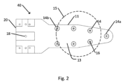
図2は、連続したグリッパ表面を有する図1に示すワークピースグリッパの変形例の概略上面図である。 Figure 2 is a schematic top view of a variation of the workpiece gripper shown in Figure 1 having a continuous gripper surface.
ワークピースグリッパ40のグリッパ本体11は、分岐していないアームを有する連続した本体の形である。同等に、ワークピースグリッパ40のグリッパ本体11は、単一のアームから構成されていると考えられ得る。同様に、グリッパ表面13は、連続した表面の形である(グリッパ表面13上の任意の2つの吸着グリッパ14が、その全長が介在する空間を横切ることなくグリッパ表面13に沿って延びる線分によって接続され得るように)。いくつかの例では、グリッパ本体11は、グリッパ本体11の対向する面に、2つの同様のまたは異なるグリッパ表面13を有してよい。
The
図示の例では、吸着グリッパ14は、2列に配置され、例えば、それぞれの列が内部吸着チャネルに沿った位置に対応する。他の例では、吸着グリッパ14は、グリッパ表面13に他の方法で配置されてよい。
In the illustrated example, the
連続したグリッパ表面13に沿った吸着グリッパ14の配置は、例えば、小さいワークピース15の実質的な部分または全体が、グリッパ表面13の異なるアーム間の空間に位置する可能性を排除することによって、異なるサイズのワークピース15を把持する際の柔軟性を高めることを可能にし得る。上述したように、それぞれの吸着グリッパ14を通る流入を制限する流量制限器は、ワークピース15によって覆われていない任意の吸着グリッパ14aを通る、またはワークピース15によって部分的に覆われている吸着グリッパ14bを通る、流入を制限し得る。
Arrangement of the
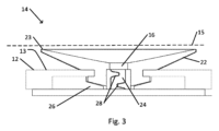
図3は、図1に示すワークピースグリッパの吸着グリッパを通る概略断面図である。 Figure 3 is a schematic cross-sectional view through the suction gripper of the workpiece gripper shown in Figure 1.
図示の例では、吸着グリッパ14は、単一の吸着開口部16を含む。他の例では、吸着グリッパは、複数の吸着開口部を含んでよい。
In the illustrated example, the
吸着は、例えば、吸着グリッパ14が配置されるグリッパアーム12に沿って、グリッパ本体11の内部に延び得る吸着チャネル26を介して、吸着開口部16に行われてよい。例えば、吸着チャネル26の近位端は、ワークピースグリッパ10の吸着コネクタ18と流体的に接続されてよい。典型的に、単一の吸着チャネル26は、1つ以上の吸着開口部16に接続されてよい。例えば、単一のグリッパアーム12に沿った全ての吸着開口部16は、単一の吸着チャネル26に開口してよい。
Suction may occur to the
図示の例では、吸着開口部16は、流量制限器24を介して吸着チャネル26に(例えば、図3に示す断面の平面外にある開口部を介して)接続されている。図示の例では、流量制限器24は、複数のバッフル28によって流れが偏向される迷路チャネルの形である。代替的にまたは追加的に、流量制限器24は、例えば、SASO構造を含む別の形、または、1つ以上のバッフル、フィン、狭窄部、湾曲部、ねじれ、屈曲部、または、吸着開口部16および流量制限器24を介した空気または別の流体の流入速度を制限するための他の構造の、別の構成を、有してよい。流量制限器24は、調整可能または調整不能なニードル弁または他の狭窄部を含んでよい。
In the illustrated example, the
図示の例では、流量制限器24は、吸着開口部16と吸着チャネル26との間に配置されている。代替的にまたは追加的に、流量制限器24は、吸着チャネル26または吸着コネクタ18内、吸着チャネル26と吸着コネクタ18との間、または吸着開口部16と吸着コネクタ18との間の流体経路の他の場所(例えば、吸着チャネル26が2つ以上の分岐チャネルに分岐し、それぞれが異なる吸着開口部16に接続する箇所)に配置されてよい。例えば、単一の流量制限器24は、2つ以上の吸着開口部16を介した流入を制限する役割を果たし得る。流量制限器24は、グリッパ基部20内、または吸着源と吸着コネクタ18との間の導管内に、配置されてよい。
In the illustrated example, the
図示の例では、吸着開口部16は、弾性カップ22の形の弾性シール構造によって取り囲まれている。ワークピース15の表面が吸着開口部16の近傍に配置され、吸着が吸着開口部16に行われるときに、ワークピース15は、吸着開口部16およびグリッパ表面13に向かって引き寄せられ得る。ワークピース15が弾性カップ22のリム23に接触するときに、ワークピース15と弾性カップ22のリム23との間の接触が、シールを形成し得る。従って、吸着は、周囲の空気圧がワークピース15を吸着開口部16に向かって押すように、弾性カップ22内に部分的な真空を形成し得る。
In the illustrated example, the
吸着開口部16の方へのワークピース15のさらなる引き寄せは、弾性カップ22をグリッパ表面13の方へ押し付け得る。弾性カップ22の柔軟性および弾性は、弾性カップ22がワークピース15とグリッパ表面13との間で平坦化することを可能にし得る。弾性カップ22の平坦化は、弾性カップ22とワークピース15との間の接触面積を増加させ得る。接触面積の増加は、ワークピース15と平坦化された弾性カップ22との間の摩擦力、従ってワークピース15と吸着グリッパ14との間の摩擦力を、増加させ得る。
Further pulling of the
代替的にまたは追加的に、弾性シール構造は、別の形態を有してよい。例えば、弾性シール構造は、パッド、ガスケット、変形可能なニップル、または、吸着開口部16とワークピース15との間にシールを形成し、ワークピース15と吸着グリッパ14との間の摩擦力を促進し得る、他の構造、の形態を有してよい。
Alternatively or additionally, the resilient sealing structure may have another form. For example, the resilient sealing structure may have the form of a pad, a gasket, a deformable nipple, or other structure that may form a seal between the
場合によっては、例えば、ワークピース15の表面が反っている場合、1つ以上の吸着グリッパ14は、吸着開口部16を覆ってワークピース15とその吸着開口部16との間に気密シールを形成するのに、ワークピース15の表面をその吸着グリッパ14の吸着開口部16の方へ十分に引き寄せないことがある。吸着開口部16と吸着コネクタ18との間の流入経路における流量制限器24の存在は、覆われていない吸着開口部16を通る流入速度を制限し得る。全ての覆われていない吸着開口部16を通る流入速度のため、覆われて密封された吸着開口部16に加えられる吸着(ワークピース15表面が、吸着開口部16の少なくともいくつか、好ましくは少なくとも3つに接触すると仮定)は、ワークピース15をしっかりと把持してワークピース15の信頼性の高い正確な操作を可能にするのに十分であり得る。(流量制限器がない場合、吸着コネクタ18を介して行われる全ての吸着は、覆われていない吸着開口部を通る流入の増加を引き起こし、覆われた吸着開口部を介した吸着の適用を中断または阻止する可能性がある。)
In some cases, for example when the surface of the
図示の例では、それぞれの吸着グリッパ14およびその弾性カップ22(または同様の弾性シール構造)は、ワークピース15に面するグリッパアーム12の表面から一定の距離延びている。それぞれのグリッパアーム12上の吸着グリッパ14の数および配置、ならびにグリッパアーム22の数および形状は、最小数量の吸着グリッパ14が、反ったワークピースであっても(例えば、ワークピース15を使用不能にしない反りの範囲内で)その表面を把持することができるように設計され得る。例えば、場合によっては、2つ以上の吸着グリッパ14によるワークピースの把持は、ワークピースグリッパ10がワークピースをしっかりと把持するのに十分であり得る。場合によっては、3つ以上の吸着グリッパ14によるワークピースの把持は、ワークピースを安定して確実に把持するのに十分であると考えられ得る。
In the illustrated example, each
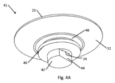
図4Aは、図3に示す吸着グリッパの変形例を概略的に示す。図4Bは、図4Aに示す吸着グリッパの概略断面図である。 Figure 4A shows a schematic diagram of a modified suction gripper shown in Figure 3. Figure 4B shows a schematic cross-sectional view of the suction gripper shown in Figure 4A.
吸着グリッパ41は、吸着グリッパ14(図3)と同様に構成され、弾性カップ22によって取り囲まれた吸着開口部16を含む。例えば、弾性カップ22は、シリコーンなどの可撓性および弾性ポリマー、または別の弾性材料から形成されてよい。
The
一例では、吸着グリッパ41は、グリッパ表面13上の円形開口部に保持されてよい。円形開口部の下のグリッパ本体11の領域は、吸着チャネル26を含んでよい。例えば、円形開口部は、吸着チャネル26に開口してよい。円形開口部の直径は、リップ46の直径よりも小さく、リップ46と弾性カップ22との間の溝48の直径よりも大きくてよい。リップ46も、弾性材料で構成されてよい。例えば、リップ46と弾性カップ22は、単一ピースとして製造、例えば、成形されてよい。
In one example, the
例えば、吸着グリッパ41をグリッパ表面13の円形開口部に取り付けるために、吸着グリッパ41のステム42は、リップ46が開口部を通過するまで、開口部に挿入されてよい(例えば、挿入中に曲げられたり、他の方法で歪められたりして)。リップ46が円形開口部を通過すると、リップ46の弾性は、円形開口部から吸着グリッパ41が外れるのを防止するように、リップ46を開き得る。例えば、リップ46の近位外面は、円形開口部を通じたリップ46の挿入を可能にするためにリップ46の曲げまたは折り畳みを容易にするように、弾性カップ22の方へ外側および遠位方向に先細りになってよい。先細りは、ステム42の方へ近位方向にリップ4が曲がるのを妨げ、従って円形開口部からのリップ46の引き抜きを妨げ得る。
For example, to attach the
図示の例では、ステム42は、平らな側面44を形成するように横方向に切り落とされた円柱の形であってよい。流量制限器24は、吸着グリッパ41の遠位端の吸着開口部16を、ステム42の側面44と、弾性カップ22およびリップ46を含む外側ピースの円筒状内表面50と、の間の領域に接続する。従って、円筒状内面50は、ステム42の長さの少なくとも一部を取り囲む。側面44と円筒状内面50との間の領域は、吸着開口部16とステム42の近位(例えば、リップ46へ)の端部との間の流体的な接続を形成する。図示の例では、流量制限器24のバッフル28は、側面42と円筒状内表面50との間の空間に位置している。
In the illustrated example, the
吸着導管26に開口している円形開口部にステム42が挿入される場合の例では、側面44に沿った場合を除くステム42の円筒状外面と円筒状内面50との間のぴったりとした境界面によって流入が遮断され得る。側面44と円筒状内面50との間の空間は、吸着開口部16と吸着導管26との間の流体的な接続を形成する。吸着開口部16と吸着導管26との間の流体的な接続は、流量制限器24を形成するための構造(図示の例ではバッフル28、または他の構造)を含む。従って、ワークピース15の表面と接触していない場合でも、吸着グリッパ41を介した流入が制限され得る。
In the example where the
吸着グリッパの他の構成も可能である。 Other configurations of suction grippers are possible.
代替的にまたは追加的に、ワークピースグリッパ10の1つ以上の吸着グリッパは、調節可能な長さだけグリッパアーム12からワークピース15の方へ伸長可能であってよい。反ったワークピースが複数の伸長可能な吸着グリッパによって把持されてグリッパアーム12の方へ引き寄せられるときに、伸長可能な吸着グリッパのいくつかは、反りを補償しながら把持を維持するように、グリッパアーム12から外側に延びてよい。
Alternatively or additionally, one or more suction grippers of the
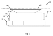
図5は、吸着グリッパがワークピースグリッパから伸長可能である吸着グリッパの変形例の概略側面図である。 Figure 5 is a schematic side view of a modified suction gripper in which the suction gripper is extendable from the workpiece gripper.
伸長可能な吸着グリッパ30は、伸長可能な吸着グリッパ30の遠位端(図示の例では、弾性カップ22が配置されている)をグリッパアーム12から可変距離だけ伸長するための伸長機構32を含む。可変距離を変化させるための伸長機構32の伸長および後退または圧縮は、矢印34で表される。
The
図示の例では、伸長可能な吸着グリッパ30は、図3に示す吸着グリッパ14と同様に構成されている。例えば、伸長可能な吸着グリッパ30は、吸着開口部16(図5の側面図では見えない)を取り囲む弾性シール構造(図示のように弾性カップ22の形態、またはパッド、ガスケット、ニップル、または他の弾性シール構造)を含む。吸着開口部16は、1つ以上の流量制限器24を、吸着開口部16と、吸着開口部16および伸長可能な吸着グリッパ30に吸着を行う吸着源(例えば、吸着コネクタ18または同様の構造)への接続部と、の間に備える。例えば、流量制限器24は、伸長可能な吸着グリッパ30、グリッパアーム12、グリッパ基部20の中、またはワークピースグリッパ10の中の他の場所に配置されてよい。
In the illustrated example, the
伸長機構32の一例では、伸長機構32は、伸長可能な吸着グリッパ30がワークピースを把持していないときに、伸長可能な吸着グリッパ30を完全に伸長するように構成される機構を含む。従って、伸長可能な吸着グリッパ30がワークピースの表面の一部を把持するまで、伸長可能な吸着グリッパ30は通常伸長する。
In one example of the
一例では、伸長機構32は、圧縮されていないときに完全に伸長する1つ以上の弾性機械要素または空気圧要素を含んでよい。例えば、弾性要素は、圧縮されていないときに完全に伸長する1つ以上の圧縮可能なばねまたは棒を含んでよい。圧縮可能な要素は、伸長機構32の遠位端付近の点から近位点、例えばグリッパアーム12内まで、伸長機構32内に延びてよい。要素が圧縮されると、伸長機構32の一部がグリッパアーム12内に押し込まれ得る、または、伸長機構32の伸縮または折り畳み可能な壁が短くなり得る。
In one example, the
別の例として、伸長機構32の外壁は、弾性アコーディオン折り目を含んでよい、または、圧縮力が伸長機構32の壁をくしゃくしゃにしたり押しつぶしたりすることを可能にする一方で、圧縮力が取り除かれると壁がその圧縮されていない伸長形状を回復することを可能にするように、別の方法で構成される。
As another example, the outer walls of the
空気圧要素は、圧縮力を受けたときに管が短くなることを可能にする2つ以上の伸縮セグメントを有するシール管を含んでよい。例えば、シール管は、伸長機構32の遠位端付近の点から、例えばグリッパアーム12内の、近位点まで、伸長機構32内に延びてよい。代替的にまたは追加的に、伸長機構32は、加圧空気または別の流体が導入され得るチャンバを含んでよい。例えば、空気は、吸着開口部16に吸着を行う吸着源の排気機構からチャンバ内に吹き込まれてよい。
The pneumatic element may include a sealing tube having two or more telescoping segments that allow the tube to shorten when subjected to a compressive force. For example, the sealing tube may extend into the
通常伸長した伸長可能な吸着グリッパ30を用いて、ワークピースの表面を(例えば、ロボットまたは他の自動機構によって、または手動制御機構によって、または他の方法で)、1つ以上の伸長した伸長可能な吸着グリッパ30を含むワークピースグリッパ10のグリッパアーム12に接近させてよい。典型的に、ワークピース15がグリッパアーム12に近づく際に、ワークピースグリッパ10のそれぞれの伸長可能な吸着グリッパ30の吸着開口部16(同様に伸長可能でない任意の吸着グリッパ14の吸着開口部16)に吸着が行われる。
Using the typically extended
典型的に、ワークピース15の表面の領域が1つ以上の伸長可能な吸着グリッパ30の遠位端に十分に近づけられると、ワークピース15の表面の1つ以上の領域が、伸長した伸長可能な伸長可能な吸着グリッパ30の遠位端で弾性シール構造の一部(例えば、弾性カップ22のリム23の一部)に最初に接触し得る。その伸長可能な吸着グリッパ30に行われる吸着は、弾性シール構造とワークピース15の表面とを共に引き寄せ得る。従って、弾性シール構造は、ワークピース15とその伸長可能な吸着グリッパ30との間にシールを形成し得る。例えば、弾性カップ22の形の弾性シール構造のリム全体は、ワークピース15の表面の方へ引き寄せられ、物理的に接触し得る。従って、弾性カップ22(または他の弾性シール構造)の内部は、唯一の開口部が吸着開口部16であるチャンバを形成し得る。
Typically, when an area of the surface of the
この場合、吸着開口部16に吸着を継続的に行うことは、ワークピース15の表面と弾性カップ22(または他の弾性封止構造)との間に形成されたチャンバから流体を引き出し得る。その結果、吸着力が、伸長機構32の遠位方向に押す力に打ち勝って、伸長可能な吸着グリッパ30の遠位端を、ワークピース15の取り付けられた表面と共に、グリッパアーム12の方へ近位方向に引き寄せ得る。ワークピース15の表面の近位内側への動きは、ワークピース15の表面が、他の伸長可能な吸着グリッパ30または吸着グリッパ14によって同様に把持される可能性を高め得る。
In this case, continued suction to the
流量制限器24の存在は、ワークピース15の表面と接触しておらず、従ってワークピース15の表面によってシールされていない、任意の伸長可能な吸着グリッパ30または吸着グリッパ14を通じた流入を制限し得る。制限された流入は、従って、ワークピース15の表面と接触している任意の伸長可能な吸着グリッパ30または吸着グリッパ14によって加えられる吸着力が、接触を維持することができることを保証し得る。
The presence of the
代替的にまたは追加的に、伸長機構32は、制御可能なモータ(例えば、モータの円運動を伸長機構32の直線運動に変換するトランスミッションを有する電動モータ)またはアクチュエータ(例えば電動式の、リニアアクチュエータ)を含んでよく、アクチュエータは、例えばワークピースグリッパ10のコントローラによって、伸長可能な吸着グリッパ30の遠位端を伸長または後退させるように動作可能である。例えば、グリッパアーム12、伸長可能な吸着グリッパ30、またはワークピースグリッパ10は、伸長可能な吸着グリッパ30の近くにあるワークピース15の表面の部分の近接を感知するように構成されたセンサを備えてよい。近接が検知されると、伸長機構32は、ワークピース15の方へ伸長可能な吸着グリッパ30を伸長させるように動作し得る。接触が検知されると(例えば、その伸長可能な吸着グリッパ30の吸着開口部16を介した流入量の減少を検出するセンサによって)、伸長機構32は、ワークピース15の表面をグリッパアーム12の方へ引っ張るように動作し得る。
Alternatively or additionally, the
伸長機構32の動作には、他の種類の機構も可能である。伸長機構32は、流量制限器24によって制限されるそれぞれの吸着開口部16を通じた制限された流入にもかかわらず、ワークピース15の表面を把持するのに表面に十分に近い伸長可能な吸着グリッパ30の遠位端の位置決めを可能にすることによって、ワークピースグリッパ10によるワークピースの把持を容易にし得る。
Other types of mechanisms are possible for the operation of the
異なる実施形態が本明細書に開示されている。特定の実施形態の特徴は、他の実施形態の特徴と組み合わせられてよく、従って、特定の実施形態は、複数の実施形態の特徴の組み合わせであってよい。本発明の実施形態の上述の記載は、例示および説明の目的で提示されている。網羅的にすることや、開示された正確な形態に本発明を限定することを意図していない。上記の教示に照らして、多くの修正、変形、置換、変更、および同等が可能であることが、当業者には理解されるであろう。従って、添付の「特許請求の範囲」は、全てのそのような修正および変更を本発明の真の趣旨の範囲内に含まれるとしてカバーすることを意図していることを、理解されたい。 Different embodiments are disclosed herein. Features of certain embodiments may be combined with features of other embodiments, and thus, a particular embodiment may be a combination of features of more than one embodiment. The foregoing description of the embodiments of the present invention has been presented for purposes of illustration and description. It is not intended to be exhaustive or to limit the invention to the precise form disclosed. It will be appreciated by those skilled in the art that many modifications, variations, substitutions, changes, and equivalents are possible in light of the above teachings. It is therefore to be understood that the appended claims are intended to cover all such modifications and variations as fall within the true spirit and scope of the present invention.
本発明の特定の特徴が本明細書で図示および説明されてきたが、多くの修正、置換、変更、および同等が、当業者には今や思い浮かぶであろう。従って、添付の「特許請求の範囲」は、全てのそのような修正および変更を本発明の真の趣旨の範囲内に含まれるとしてカバーすることを意図していることを、理解されたい。
While certain features of the invention have been illustrated and described herein, many modifications, substitutions, changes, and equivalents will now occur to those skilled in the art. It is therefore to be understood that the appended claims are intended to cover all such modifications and changes as fall within the true spirit of the invention.
Claims (16)
前記グリッパ表面は、前記グリッパ表面上に分配された複数の開口部を含み、前記開口部のそれぞれは、吸着源に接続可能であり、
前記少なくとも1つの流量制限器は、前記複数の開口部と、前記吸着源への前記グリッパのコネクタと、の間に配置され、前記複数の開口部のそれぞれの開口部を通じた流入を制限し、吸着が前記複数の開口部に行われ、ワークピース表面の一部が、前記複数の開口部のうちの少なくとも1つの開口部を覆い、別の開口部が覆われていないままであるとき、覆われた開口部での吸着力が、前記ワークピース表面を把持するのに十分な強さであり、
前記複数の開口部の開口部は、弾性シール構造を含み、前記弾性シール構造は、前記ワークピース表面が前記弾性シール構造と接触しているときに、吸着がその開口部に行われたときに、その開口部と前記ワークピース表面との間にシールを形成するように構成され、
前記弾性シール構造は、前記複数の開口部の前記開口部に挿入可能なステムを介して、前記グリッパ表面に接続可能であり、
前記ステムは、平らな側面を形成するように横方向に切り落とされたシリンダの形であり、
前記少なくとも1つの流量制限器は、前記側面と、前記ステムを取り囲む円筒面と、の間の空間に配置される、グリッパ。 A gripper for gripping a workpiece , the gripper comprising : a body having a flat gripper surface; and at least one flow restrictor;
the gripper surface includes a plurality of openings distributed on the gripper surface, each of the openings being connectable to a suction source;
the at least one flow restrictor is disposed between the plurality of openings and a connector of the gripper to the suction source and restricts flow through each opening of the plurality of openings such that when suction is applied to the plurality of openings and a portion of a workpiece surface covers at least one opening of the plurality of openings while another opening remains uncovered, a suction force at the covered opening is strong enough to grip the workpiece surface;
an opening of the plurality of openings includes a resilient seal structure configured to form a seal between the opening and the workpiece surface when suction is applied to the opening when the workpiece surface is in contact with the resilient seal structure;
the resilient sealing structure is connectable to the gripper surface via a stem insertable into an opening of the plurality of openings;
said stem being in the form of a cylinder cut transversely to form flat sides;
The at least one flow restrictor is disposed in a space between the side surface and a cylindrical surface surrounding the stem .
Applications Claiming Priority (3)
| Application Number | Priority Date | Filing Date | Title |
|---|---|---|---|
| US201962848601P | 2019-05-16 | 2019-05-16 | |
| US62/848,601 | 2019-05-16 | ||
| PCT/IL2020/050514 WO2020230125A1 (en) | 2019-05-16 | 2020-05-13 | Suction gripper for warped workpiece |
Publications (2)
| Publication Number | Publication Date |
|---|---|
| JP2022532720A JP2022532720A (en) | 2022-07-19 |
| JP7586840B2 true JP7586840B2 (en) | 2024-11-19 |
Family
ID=73288861
Family Applications (1)
| Application Number | Title | Priority Date | Filing Date |
|---|---|---|---|
| JP2021567842A Active JP7586840B2 (en) | 2019-05-16 | 2020-05-13 | Vacuum gripper for warped workpieces |
Country Status (7)
| Country | Link |
|---|---|
| US (1) | US12327753B2 (en) |
| EP (1) | EP3969400A4 (en) |
| JP (1) | JP7586840B2 (en) |
| KR (1) | KR102867740B1 (en) |
| CN (1) | CN113853348B (en) |
| TW (1) | TWI875759B (en) |
| WO (1) | WO2020230125A1 (en) |
Families Citing this family (3)
| Publication number | Priority date | Publication date | Assignee | Title |
|---|---|---|---|---|
| KR20230127984A (en) * | 2021-01-11 | 2023-09-01 | 에이에스엠엘 네델란즈 비.브이. | A gripper and a lithographic apparatus including the gripper |
| JP7641187B2 (en) * | 2021-06-23 | 2025-03-06 | 株式会社ダイヘン | Workpiece transport hand |
| CN114131621B (en) * | 2021-10-29 | 2024-12-24 | 赛莱克斯微系统科技(北京)有限公司 | A wafer transport robot |
Citations (8)
| Publication number | Priority date | Publication date | Assignee | Title |
|---|---|---|---|---|
| JP2002517088A (en) | 1998-05-27 | 2002-06-11 | バリアン・セミコンダクター・エクイップメント・アソシエイツ・インコーポレイテッド | Batch type end effector for semiconductor wafer handling |
| JP2003509227A (en) | 1999-08-25 | 2003-03-11 | コア フロー リミテッド | Automatic adaptive vacuum holding system |
| JP2004119488A (en) | 2002-09-24 | 2004-04-15 | Tokyo Electron Ltd | Vacuum suction device, substrate transfer device and substrate processing device |
| US20060054774A1 (en) | 2001-12-27 | 2006-03-16 | Yuval Yassour | High-performance non-contact support platforms |
| JP2011211119A (en) | 2010-03-30 | 2011-10-20 | Fuji Electric Co Ltd | Wafer carrying device and wafer carrying method |
| JP5379589B2 (en) | 2009-07-24 | 2013-12-25 | 東京エレクトロン株式会社 | Vacuum suction pad, transfer arm and substrate transfer device |
| JP2018140445A (en) | 2015-07-20 | 2018-09-13 | ライフロボティクス株式会社 | Robot device |
| JP2018157221A (en) | 2014-03-06 | 2018-10-04 | カスケード マイクロテック インコーポレイテッドCascade Microtech,Incorporated | Wafer handling end effector |
Family Cites Families (17)
| Publication number | Priority date | Publication date | Assignee | Title |
|---|---|---|---|---|
| IL131589A (en) * | 1999-08-25 | 2007-05-15 | Yuval Yassour | Apparatus for inducing forces by fluid injection |
| US6467824B2 (en) * | 2001-03-13 | 2002-10-22 | Data I/O Corporation | Floating seal pick and place system and unit therefor |
| JP2004119448A (en) | 2002-09-24 | 2004-04-15 | Nec Kyushu Ltd | Apparatus and method for plasma etching |
| US7055875B2 (en) * | 2003-07-11 | 2006-06-06 | Asyst Technologies, Inc. | Ultra low contact area end effector |
| US8382174B2 (en) * | 2009-10-08 | 2013-02-26 | University Of Maryland | System, method, and apparatus for suction gripping |
| KR20140124871A (en) * | 2011-02-28 | 2014-10-27 | 샌디스크 세미컨덕터 (상하이) 컴퍼니, 리미티드 | Non-uniform vacuum profile die attach tip |
| US9401296B2 (en) * | 2011-11-29 | 2016-07-26 | Persimmon Technologies Corporation | Vacuum robot adapted to grip and transport a substrate and method thereof with passive bias |
| DE102011056029A1 (en) | 2011-12-05 | 2013-06-06 | Rehau Ag + Co | Transport method for storing fiber mats, transport device and a device for gripping a flat semi-finished product |
| US8864202B1 (en) * | 2013-04-12 | 2014-10-21 | Varian Semiconductor Equipment Associates, Inc. | Spring retained end effector contact pad |
| JP5861677B2 (en) * | 2013-07-08 | 2016-02-16 | 株式会社安川電機 | Adsorption structure, robot hand and robot |
| JP6224437B2 (en) * | 2013-11-26 | 2017-11-01 | 東京エレクトロン株式会社 | Substrate transfer device |
| US9415519B2 (en) * | 2014-07-01 | 2016-08-16 | Varian Semiconductor Equipment Associates, Inc. | Composite end effector and method of making a composite end effector |
| CA2996868C (en) * | 2015-08-26 | 2021-02-16 | Berkshire Grey, Inc. | Systems and methods for providing vacuum valve assemblies for end effectors |
| CN105552016A (en) * | 2015-12-23 | 2016-05-04 | 苏州工业园区纳米产业技术研究院有限公司 | Structure transformation and transformation method for coating machine manipulator suitable for warped wafer |
| KR101820722B1 (en) * | 2016-05-17 | 2018-01-24 | 금오공과대학교 산학협력단 | Apparatus of vacuum adhesion for plat panel |
| US9975255B1 (en) * | 2016-12-15 | 2018-05-22 | Jabil Inc. | Apparatus, system and method for providing a conformable vacuum cup for an end effector |
| JP6442563B1 (en) * | 2017-05-30 | 2018-12-19 | キヤノン株式会社 | Conveying hand, conveying apparatus, lithographic apparatus, article manufacturing method and holding mechanism |
-
2020
- 2020-05-13 EP EP20805594.7A patent/EP3969400A4/en not_active Withdrawn
- 2020-05-13 JP JP2021567842A patent/JP7586840B2/en active Active
- 2020-05-13 TW TW109115930A patent/TWI875759B/en active
- 2020-05-13 WO PCT/IL2020/050514 patent/WO2020230125A1/en not_active Ceased
- 2020-05-13 US US17/607,029 patent/US12327753B2/en active Active
- 2020-05-13 CN CN202080036144.6A patent/CN113853348B/en active Active
- 2020-05-13 KR KR1020217041171A patent/KR102867740B1/en active Active
Patent Citations (8)
| Publication number | Priority date | Publication date | Assignee | Title |
|---|---|---|---|---|
| JP2002517088A (en) | 1998-05-27 | 2002-06-11 | バリアン・セミコンダクター・エクイップメント・アソシエイツ・インコーポレイテッド | Batch type end effector for semiconductor wafer handling |
| JP2003509227A (en) | 1999-08-25 | 2003-03-11 | コア フロー リミテッド | Automatic adaptive vacuum holding system |
| US20060054774A1 (en) | 2001-12-27 | 2006-03-16 | Yuval Yassour | High-performance non-contact support platforms |
| JP2004119488A (en) | 2002-09-24 | 2004-04-15 | Tokyo Electron Ltd | Vacuum suction device, substrate transfer device and substrate processing device |
| JP5379589B2 (en) | 2009-07-24 | 2013-12-25 | 東京エレクトロン株式会社 | Vacuum suction pad, transfer arm and substrate transfer device |
| JP2011211119A (en) | 2010-03-30 | 2011-10-20 | Fuji Electric Co Ltd | Wafer carrying device and wafer carrying method |
| JP2018157221A (en) | 2014-03-06 | 2018-10-04 | カスケード マイクロテック インコーポレイテッドCascade Microtech,Incorporated | Wafer handling end effector |
| JP2018140445A (en) | 2015-07-20 | 2018-09-13 | ライフロボティクス株式会社 | Robot device |
Also Published As
| Publication number | Publication date |
|---|---|
| EP3969400A1 (en) | 2022-03-23 |
| KR20220008899A (en) | 2022-01-21 |
| KR102867740B1 (en) | 2025-10-13 |
| US20220216090A1 (en) | 2022-07-07 |
| TW202101660A (en) | 2021-01-01 |
| EP3969400A4 (en) | 2023-06-14 |
| JP2022532720A (en) | 2022-07-19 |
| TWI875759B (en) | 2025-03-11 |
| WO2020230125A1 (en) | 2020-11-19 |
| CN113853348A (en) | 2021-12-28 |
| US12327753B2 (en) | 2025-06-10 |
| CN113853348B (en) | 2025-02-21 |
Similar Documents
| Publication | Publication Date | Title |
|---|---|---|
| JP7586840B2 (en) | Vacuum gripper for warped workpieces | |
| JP6514254B2 (en) | Gripping tool and gripping system | |
| US20090142169A1 (en) | Vacuum Assisted Manipulation of Objects | |
| US11298833B2 (en) | Gripper, grasping device, and industrial robot | |
| US20190210231A1 (en) | Gripping tool and gripping system | |
| US20250096021A1 (en) | Chuck for acquiring a warped workpiece | |
| US10875196B2 (en) | Gripping device and industrial robot | |
| CN110877344A (en) | Multi-degree-of-freedom pneumatic flexible manipulator | |
| US11267137B1 (en) | Controlling end effector suction area using expandable bladder | |
| US20200238541A1 (en) | Gripping device and industrial robot | |
| US11749551B2 (en) | Chuck for acquiring a warped workpiece | |
| JP3917528B2 (en) | Suction pad | |
| CN115052720A (en) | End effector, programmable motion device, and method of operating a programmable motion device | |
| JP2012009751A (en) | Vacuum tweezers | |
| US10625428B2 (en) | End effector with selectively deformable interface | |
| CN1152534A (en) | Vacuum tweezers | |
| JP2024517231A (en) | Chuck for catching warped workpieces | |
| JP2012009540A (en) | Vacuum tweezers | |
| CN120641250A (en) | Gripper module for improving the grip of objects | |
| KR20250006291A (en) | Substrate container with door gasket | |
| JP2018122408A (en) | Gripping device | |
| JP2000312428A (en) | Cable guide device | |
| KR20030055663A (en) | Tweezer for moving wafer |
Legal Events
| Date | Code | Title | Description |
|---|---|---|---|
| A621 | Written request for application examination |
Free format text: JAPANESE INTERMEDIATE CODE: A621 Effective date: 20230511 |
|
| A977 | Report on retrieval |
Free format text: JAPANESE INTERMEDIATE CODE: A971007 Effective date: 20240531 |
|
| A131 | Notification of reasons for refusal |
Free format text: JAPANESE INTERMEDIATE CODE: A131 Effective date: 20240625 |
|
| A521 | Request for written amendment filed |
Free format text: JAPANESE INTERMEDIATE CODE: A523 Effective date: 20240920 |
|
| TRDD | Decision of grant or rejection written | ||
| A01 | Written decision to grant a patent or to grant a registration (utility model) |
Free format text: JAPANESE INTERMEDIATE CODE: A01 Effective date: 20241008 |
|
| A61 | First payment of annual fees (during grant procedure) |
Free format text: JAPANESE INTERMEDIATE CODE: A61 Effective date: 20241107 |
|
| R150 | Certificate of patent or registration of utility model |
Ref document number: 7586840 Country of ref document: JP Free format text: JAPANESE INTERMEDIATE CODE: R150 |