JP7581393B2 - Substrate Processing Equipment - Google Patents
Substrate Processing Equipment Download PDFInfo
- Publication number
- JP7581393B2 JP7581393B2 JP2023008307A JP2023008307A JP7581393B2 JP 7581393 B2 JP7581393 B2 JP 7581393B2 JP 2023008307 A JP2023008307 A JP 2023008307A JP 2023008307 A JP2023008307 A JP 2023008307A JP 7581393 B2 JP7581393 B2 JP 7581393B2
- Authority
- JP
- Japan
- Prior art keywords
- substrate
- liquid
- mounting table
- hole
- cooling
- Prior art date
- Legal status (The legal status is an assumption and is not a legal conclusion. Google has not performed a legal analysis and makes no representation as to the accuracy of the status listed.)
- Active
Links
Images


Landscapes
- Cleaning Or Drying Semiconductors (AREA)
Description
本発明の実施形態は、基板処理装置に関する。 An embodiment of the present invention relates to a substrate processing apparatus.
インプリント用テンプレート、フォトリソグラフィ用マスク、半導体ウェーハなどの基板の表面に付着したパーティクルなどの汚染物を除去する方法として、凍結洗浄法が提案されている。 Freeze cleaning has been proposed as a method for removing particles and other contaminants from the surfaces of substrates such as imprint templates, photolithography masks, and semiconductor wafers.
凍結洗浄法においては、まず、基板の表面に純水などの液体を供給して液膜を形成する。次に、基板の表面側に冷却ガスを供給して液膜を凍結させる。液膜が凍結して凍結膜が形成される際に汚染物が凍結膜に取り込まれることで、汚染物が基板の表面から分離される。次に、凍結膜に純水などの液体を供給して凍結膜を融解し、液体とともに汚染物を基板の表面から除去する。(例えば、特許文献1を参照)
凍結洗浄法を実施可能な基板処理装置を用いれば、基板の表面から汚染物を効率よく除去することができる。
In the freeze cleaning method, first, a liquid such as pure water is supplied to the surface of the substrate to form a liquid film. Next, a cooling gas is supplied to the surface side of the substrate to freeze the liquid film. When the liquid film freezes to form a frozen film, contaminants are captured in the frozen film, and the contaminants are separated from the surface of the substrate. Next, a liquid such as pure water is supplied to the frozen film to melt it, and the contaminants are removed from the surface of the substrate together with the liquid (see, for example, Patent Document 1).
By using a substrate processing apparatus capable of carrying out the freeze cleaning method, contaminants can be efficiently removed from the surface of a substrate.
しかしながら、凍結洗浄法を実施可能な基板処理装置においては、基板の周辺において、基板の表面に供給された液体が凍結したり、凍結洗浄処理を行う雰囲気に含まれている水分により霜が発生したりするという問題がある。
そのため、基板の周辺において不要な凍結が生じるのを抑制することができる基板処理装置の開発が望まれていた。
However, in substrate processing apparatuses capable of performing the freeze cleaning method, there are problems in that the liquid supplied to the surface of the substrate may freeze around the substrate, and frost may be generated due to moisture contained in the atmosphere in which the freeze cleaning process is performed.
Therefore, there has been a demand for the development of a substrate processing apparatus capable of suppressing the occurrence of unnecessary freezing around the substrate.
本発明が解決しようとする課題は、基板の周辺において不要な凍結が生じるのを抑制することができる基板処理装置を提供することである。 The problem that the present invention aims to solve is to provide a substrate processing apparatus that can prevent unnecessary freezing from occurring around the substrate.
実施形態に係る基板処理装置は、中心軸周りに回転可能な載置台と、前記載置台に設けられ、基板を保持する複数の保持部と、前記載置台と前記基板との間の空間に、冷却ガスを供給可能な冷却部と、前記基板の、前記載置台側とは反対側の面に液体を供給可能な液体供給部と、を備えている。前記基板を保持する際には、前記複数の保持部のそれぞれは、前記載置台の面に沿って、前記中心軸に向かう方向に移動して、前記基板の周縁、および、前記載置台と前記基板との間の空間を囲み、前記空間が、前記複数の保持部により閉鎖される。
A substrate processing apparatus according to an embodiment includes a mounting table rotatable about a central axis, a plurality of holders provided on the mounting table for holding a substrate, a cooling unit capable of supplying a cooling gas to a space between the mounting table and the substrate, and a liquid supply unit capable of supplying a liquid to a surface of the substrate opposite to the mounting table. When holding the substrate, each of the plurality of holders moves along the surface of the mounting table in a direction toward the central axis to surround the periphery of the substrate and the space between the mounting table and the substrate, and the space is closed by the plurality of holders .
本発明の実施形態によれば、基板の周辺において不要な凍結が生じるのを抑制することができる基板処理装置が提供される。 According to an embodiment of the present invention, a substrate processing apparatus is provided that can prevent unnecessary freezing from occurring around the substrate.
以下、図面を参照しつつ、実施の形態について例示をする。なお、各図面中、同様の構成要素には同一の符号を付して詳細な説明は適宜省略する。
以下に例示をする基板100は、例えば、半導体ウェーハ、インプリント用テンプレート、フォトリソグラフィ用マスク、MEMS(Micro Electro Mechanical Systems)に用いられる板状体、フラットパネルディスプレイ用基板などとすることができる。ただし、基板100は、例示をしたものに限定されるわけではない。
Hereinafter, an embodiment will be described with reference to the drawings. In the drawings, the same components are denoted by the same reference numerals, and detailed description thereof will be omitted as appropriate.
The
なお、基板100の洗浄面には、パターンである凹凸部が形成されていてもよいし、凹凸部が形成されていなくてもよい。凹凸部が形成されていない基板は、例えば、凹凸部が形成される前の基板(例えば、いわゆるバルク基板)などとすることができる。
The cleaning surface of the
また、以下においては、一例として、基板100が、フォトリソグラフィ用マスクである場合を説明する。基板100が、フォトリソグラフィ用マスクである場合には、基板100の平面形状は、例えば、正方形とすることができる。
In the following, as an example, a case where the
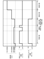
図1は、本実施の形態に係る基板処理装置1を例示するための模式断面図である。
図2は、図1における載置部2の模式断面図である。
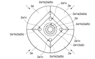
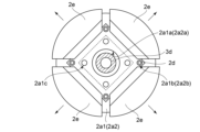
図3は、図1における載置部2のA-A線方向の模式図である。
図1~図3は、載置部2(載置台2a)に基板100を載置した状態、すなわち、基板100に凍結洗浄処理を施す際の状態を表している。
FIG. 1 is a schematic cross-sectional view illustrating a
FIG. 2 is a schematic cross-sectional view of the
FIG. 3 is a schematic diagram of the
1 to 3 show a state in which a
図1に示すように、基板処理装置1には、例えば、載置部2、冷却部3、第1液体供給部4、第2液体供給部5、チャンバ6、送風部7、排気部8、およびコントローラ9が設けられている。
As shown in FIG. 1, the
図1~図3に示すように、載置部2は、例えば、載置台2a、回転軸2b、駆動部2c、リフトピン2d、および保持部2eを有する。
As shown in Figures 1 to 3, the
載置台2aは、チャンバ6の内部に設けられている。載置台2aは、中心軸周りに回転可能となっている。
載置台2aは、例えば、部分2a1(第2の部分の一例に相当する)、および部分2a2(第1の部分の一例に相当する)を有する(図2参照)。
部分2a1は、板状を呈している。部分2a1は、例えば、円板状を呈している。部分2a1は、部分2a2の上に設けられている。また、部分2a1の上面は、平坦な面であり、載置台2aの面に相当する。部分2a1の中央部分には、部分2a1の厚み方向を貫通する孔2a1a(第1の孔の一例に相当する)が設けられている。また、部分2a1の、リフトピン2dと対向する位置には、部分2a1の厚み方向を貫通する孔2a1bが設けられている。また、部分2a1の、孔2a1aと孔2a1bとの間の領域には、載置台2a(部分2a1)と基板100との間の空間に供給された冷却ガス3a1を排出するための孔2a1c(第2の孔の一例に相当する)が設けられている。孔2a1cは、部分2a1を厚み方向に貫通している。孔2a1cは、少なくとも1つ設けることができる。ただし、複数の孔2a1cが設けられていれば、前述した冷却ガス3a1の排出が容易となる。また、複数の孔2a1cは、載置台2aの中心軸を中心として、点対称となる位置に設けることができる。この様にすれば、載置台2aの中心軸に対して均等な排気を行うことができるので、基板100の面内の温度がばらつくのを抑制することができる。
The mounting table 2a is provided inside the
The mounting table 2a has, for example, a portion 2a1 (corresponding to an example of a second portion) and a portion 2a2 (corresponding to an example of a first portion) (see FIG. 2).
The portion 2a1 has a plate shape. The portion 2a1 has, for example, a disk shape. The portion 2a1 is provided on the portion 2a2. The upper surface of the portion 2a1 is a flat surface, which corresponds to the surface of the mounting table 2a. A hole 2a1a (corresponding to an example of a first hole) penetrating the thickness direction of the portion 2a1 is provided in the center of the portion 2a1. A hole 2a1b penetrating the thickness direction of the portion 2a1 is provided in a position of the portion 2a1 facing the
また、孔2a1cが載置台2aに載置された基板100の四隅周辺に設けられることで、最終的に基板100の四隅周辺から載置台2aの外部に冷却ガス3a1が排出される。このため、基板100と載置台2aの間に基板100の四隅へと向かう冷却ガス3a1の流れが生まれ、基板100の四隅も十分冷却される。
また、載置台2aの外部に冷却ガス3a1を排出する流路2a3は、基板100の四隅に向かう方向(冷却ガス3a1を排出するための孔2a1cの中心と孔2a1cの中心を結んだ線の方向)に平行な方向に設けられることが好ましい。
Furthermore, by providing holes 2a1c around the four corners of
In addition, it is preferable that the flow path 2a3 for discharging the cooling gas 3a1 to the outside of the mounting table 2a be provided in a direction parallel to the direction toward the four corners of the substrate 100 (the direction of the line connecting the center of the hole 2a1c for discharging the cooling gas 3a1 and the center of the hole 2a1c).
部分2a2は、板状を呈している。部分2a2は、例えば、円板状を呈している。部分2a2の中央部分には、部分2a2の厚み方向を貫通する孔2a2a(第3の孔の一例に相当する)が設けられている。孔2a2aは、孔2a1aと同芯に設けることができる。また、部分2a2の、リフトピン2dと対向する位置には、部分2a2の厚み方向を貫通する孔2a2bが設けられている。孔2a2bは、孔2a1bと同芯に設けることができる。
The portion 2a2 is plate-shaped. The portion 2a2 is, for example, disk-shaped. A hole 2a2a (corresponding to an example of a third hole) is provided in the center of the portion 2a2, penetrating the thickness direction of the portion 2a2. The hole 2a2a can be provided concentrically with the hole 2a1a. Furthermore, a hole 2a2b is provided in the portion 2a2 at a position facing the
部分2a2の平面形状、平面寸法、および厚みは、部分2a1の平面形状、平面寸法、および厚みと同じとすることもできるし、これらの少なくともいずれかが異なるものとすることもできる。 The planar shape, planar dimensions, and thickness of portion 2a2 may be the same as the planar shape, planar dimensions, and thickness of portion 2a1, or at least any of these may be different.
部分2a1と部分2a2との間には、載置台2a(部分2a1)と基板100との間の空間に供給された冷却ガス3a1を、載置台2aの外部に排出する流路2a3が設けられている。流路2a3は、例えば、載置台2aの外部に繋がっている。また、流路2a3は、例えば、冷却ノズル3dと、孔2a1aおよび孔2a2aと、の間の隙間(第1の隙間の一例に相当する)に繋がっている。また、孔2a1cは、流路2a3と、載置台2aと基板100との間の空間と、に繋がっている。
Between the portion 2a1 and the portion 2a2, a flow path 2a3 is provided that discharges the cooling gas 3a1 supplied to the space between the mounting table 2a (portion 2a1) and the
後述するように、基板100の周縁と、載置台2a(部分2a1)と基板100との間の空間は、保持部2eにより囲まれている。そのため、載置台2a(部分2a1)と基板100との間の空間に供給された冷却ガス3a1は、孔2a1c、および流路2a3を介して、載置台2aの外側に排出される。また、載置台2a(部分2a1)と基板100との間の空間に供給された冷却ガス3a1は、孔2a1a、および流路2a3を介して、載置台2aの外側に排出される。
As described below, the periphery of the
流路2a3は、例えば、溝とすることができる。溝は、少なくとも1つ設けることができる。ただし、複数の溝(流路2a3)が設けられていれば、前述した冷却ガス3a1の排出が容易となる。また、複数の溝(流路2a3)は、載置台2aの中心軸を中心として、点対称となる位置に設けることができる。この様にすれば、載置台2aの中心軸に対して均等な排気を行うことができるので、基板100の面内の温度がばらつくのを抑制することができる。また、溝は、部分2a1、および部分2a2の少なくともいずれかに設けることができる。
また、部分2a1の部分2a2と対向する面、および、部分2a2の部分2a1と対向する面の少なくともいずれかに突起を設け、部分2a1と部分2a2との間に設けられた隙間を流路2a3としてもよい。この様にすれば、冷却ガス3a1の排出が容易となり、且つ、載置台2aの中心軸に対して均等な排気を行うことが容易となる。基板100の面内の温度がばらつくのをさらに効果的に抑制することができる。
The flow path 2a3 may be, for example, a groove. At least one groove may be provided. However, if multiple grooves (flow paths 2a3) are provided, the cooling gas 3a1 described above may be easily discharged. The multiple grooves (flow paths 2a3) may be provided at positions that are point symmetrical with respect to the central axis of the mounting table 2a. In this way, the exhaust can be performed uniformly with respect to the central axis of the mounting table 2a, so that the temperature variation within the surface of the
In addition, a protrusion may be provided on at least one of the surface of the portion 2a1 facing the portion 2a2 and the surface of the portion 2a2 facing the portion 2a1, and the gap provided between the portion 2a1 and the portion 2a2 may be used as the flow path 2a3. In this way, the cooling gas 3a1 can be easily discharged, and it is easy to uniformly exhaust the gas with respect to the central axis of the mounting table 2a. The temperature variation within the surface of the
図1に示すように、回転軸2bの一方の端部は、部分2a2の、部分2a1の側とは反対の面に設けられている。回転軸2bの他方の端部は、チャンバ6の外部に設けられている。回転軸2bは、チャンバ6の外部において駆動部2cと接続されている。
As shown in FIG. 1, one end of the
回転軸2bは、例えば、筒状を呈している。回転軸2bの載置台2a(部分2a2)側の端部は、開口している。
回転軸2bの、載置台2a側とは反対側の端部には、冷却ノズル3dが取り付けられている。回転軸2bの、載置台2a側とは反対側の端部と、冷却ノズル3dとの間には、図示しない回転軸シールが設けられている。そのため、回転軸2bの、載置台2a側とは反対側の端部は、気密となるように封止されている。
The
A cooling
駆動部2cは、チャンバ6の外部に設けられている。駆動部2cは、回転軸2bと接続されている。駆動部2cは、モータなどの回転機器を有する。駆動部2cの回転力は、回転軸2bを介して載置台2aに伝達される。そのため、駆動部2cにより載置台2a、ひいては複数の保持部2eに保持された基板100を回転させることができる。
The driving
また、駆動部2cは、回転の開始と回転の停止のみならず、回転数(回転速度)を変化させることができる。この場合、駆動部2cは、例えば、サーボモータなどの制御モータを備えたものとすることができる。
The driving
リフトピン2dは、棒状を呈し、複数設けることができる。リフトピン2dは、部分2a1の孔2a1b、および、部分2a2の孔2a2bに挿入可能となっている。複数のリフトピン2dは、図示しない昇降装置により昇降される。複数のリフトピン2dは、保持部2eと、図示しない搬送装置との間で基板100の受け渡しを行う(図8参照)。
The lift pins 2d are rod-shaped and multiple lift pins can be provided. The lift pins 2d can be inserted into the holes 2a1b in the portion 2a1 and the holes 2a2b in the portion 2a2. The
保持部2eは、基板100を保持する。保持部2eは、載置台2a(部分2a1)の一方の主面に、複数設けられる。例えば、図3に示すように、保持部2eは、基板100の辺ごとに設けることができる。複数の保持部2eのそれぞれは、載置台2a(部分2a1)の面に沿って、回転軸2bに向かう方向に移動可能となっている。また、複数の保持部2eのそれぞれは、回転軸2bから離れる方向に移動可能となっている(図9参照)。
The holding
例えば、図3に示すように、基板100を保持する際には、複数の保持部2eのそれぞれは、載置台2a(部分2a1)の面に沿って、中心軸に向かう方向に移動する。複数の保持部2eは、基板100を保持するとともに、基板100の周縁、および、載置台2a(部分2a1)と基板100との間の空間を囲む。
また、複数の保持部2eにより基板100が保持されると、載置台2a(部分2a1)の面に平行な方向、および、載置台2a(部分2a1)の面に垂直な方向における、基板100の位置合わせが行われる。
3, when holding the
Furthermore, when the
図3に示すように、複数の保持部2eが、載置された基板100を保持した際には、複数の保持部2eの外形寸法は、基板100の角を含む外接円よりも大きくすることができる。なお、図3に例示をした複数の保持部2eの輪郭は円であるが、四角形や六角形などの多角形としてもよい。
As shown in FIG. 3, when the multiple holding
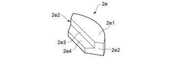
図4は、保持部2eを例示するための模式斜視図である。
図4に示すように、保持部2eは、板状を呈し、上面2e1、側面2e2、内側面2e3、および斜面2e4を有する。
上面2e1は、例えば、載置台2a(部分2a1)の面に略平行な平坦面となっている。上面2e1の、基板100側(内側面2e3側)の辺の長さは、基板100の表面100bの辺の長さと略同じになっている。また、複数の保持部2eが、載置された基板100を保持した際には、上面2e1と、載置台2a(部分2a1)の面との間の距離が、基板100の表面100bと、載置台2a(部分2a1)の面との間の距離と同じになる。つまり、複数の保持部2eが基板100を保持したときには、上面2e1と基板100の表面100bとが同じ高さになる。なお、上面2e1と、載置台2a(部分2a1)の面との間の距離が、基板100の表面100bと、載置台2a(部分2a1)の面との間の距離よりも、0.1mm程度小さくなるようにしてもよい。
FIG. 4 is a schematic perspective view illustrating the holding
As shown in FIG. 4, the holding
The upper surface 2e1 is, for example, a flat surface that is approximately parallel to the surface of the mounting table 2a (part 2a1). The length of the side of the upper surface 2e1 on the
そのため、図1~図3に示すように、複数の保持部2eが、載置された基板100を保持した際には、基板100の周囲を囲み、且つ、基板100の表面100bと略同一面内にある平坦面が形成される。この様にすれば、後述する解凍工程において、液体101と、液体101が凍結したものと、を基板100の表面100bから円滑に排出することができる。
As a result, as shown in Figures 1 to 3, when the multiple holding
図4に示すように、側面2e2は、上面2e1に接続されている。側面2e2は、例えば、載置台2a(部分2a1)の面に略垂直な平坦面となっている。図3に示すように、複数の保持部2eが、載置された基板100を保持した際には、隣接する保持部2eの側面2e2同士が接触する。
As shown in FIG. 4, the side surface 2e2 is connected to the upper surface 2e1. The side surface 2e2 is, for example, a flat surface that is approximately perpendicular to the surface of the mounting table 2a (portion 2a1). As shown in FIG. 3, when the multiple holding
内側面2e3は、上面2e1と側面2e2に接続されている。内側面2e3は、基板100の側面と対向している。内側面2e3は、例えば、載置台2a(部分2a1)の面に略垂直な平坦面となっている。図1~図3に示すように、複数の保持部2eが、載置された基板100を保持した際には、内側面2e3は、基板100の側面と接触する。
The inner surface 2e3 is connected to the upper surface 2e1 and the side surface 2e2. The inner surface 2e3 faces the side surface of the
そのため、図1~図3に示すように、複数の保持部2eが、載置された基板100を保持した際には、載置台2a(部分2a1)と基板100との間の空間が、複数の保持部2eにより閉鎖される。この様にすれば、載置台2a(部分2a1)と基板100との間の空間を流れる冷却ガス3a1が、基板100の外側に流れるのを抑制することができる。
Therefore, as shown in Figures 1 to 3, when the multiple holding
ここで、後述する予備工程、冷却工程、解凍工程などにおいて、基板100の表面100bに供給された液体101と、載置台2a(部分2a1)と基板100との間の空間に供給された冷却ガス3a1とが、基板100の周縁の近傍において交わる。すると、基板100の周辺において、載置台2aや載置台2aの近傍に設けられた部材などが凍結するおそれがある。なお、基板100の周縁の近傍には、基板100の裏面100aの外周も含まれる。つまり、基板100の裏面100aの外周に液体101が回り込むおそれがある。基板100の裏面100aに回り込んだ液体101は、汚染物を含んでいるおそれがあり、基板100の裏面100aを汚染するおそれがある。
また、冷却ガス3a1が基板100の外側に流れると、凍結洗浄処理を行う雰囲気に含まれている水分により、基板100の周縁近傍や、載置台2aの近傍に設けられた部材などに霜が発生するおそれがある。
基板100の周辺において、これらのような不要な凍結が生じると、基板処理装置1の故障が発生したり、凍結洗浄処理の効果が低減したりするおそれがある。
Here, in the preliminary process, cooling process, thawing process, etc. described later, the liquid 101 supplied to the
Furthermore, if the cooling gas 3a1 flows to the outside of the
If such unwanted freezing occurs around the
本実施の形態に係る保持部2eとすれば、冷却ガス3a1が、基板100の外側に流れるのを抑制することができるので、基板100の周辺において不要な凍結が生じるのを抑制することができる。また、基板100の裏面100aにおける凍結も抑制することができる。
The holding
斜面2e4は、図4に示すように、内側面2e3と側面2e2に接続されている。斜面2e4は、基板100の裏面100aの下方に位置している。斜面2e4は、載置台2a(部分2a1)の面(基板100の裏面100a)に対して傾斜している。斜面2e4と、載置台2a(部分2a1)の面との間の距離は、内側面2e3側になるに従い漸増している。
As shown in FIG. 4, the inclined surface 2e4 is connected to the inner surface 2e3 and the side surface 2e2. The inclined surface 2e4 is located below the
基板100を、複数の保持部2eに保持させた際には、基板100の裏面100aの縁(エッジ)が、斜面2e4と接触する。そのため、保持部2eと、基板100の裏面100aの縁とを線接触させることができる。保持部2eと、基板100の裏面100aの縁とを線接触させれば、基板100に汚れや損傷などが発生するのを抑制することができる。
また、基板100の裏面100aの縁に面取り加工が施されている場合がある。この場合には、面取り加工が施された部分が、斜面2e4と接触する。そのため、基板100の裏面100aが保持部2eと接触するのを抑制することができるので、基板100の裏面100aに損傷や汚れなどが発生するのをより抑制することができる。
また、保持部2eの斜面2e4をバリカンの刃のように櫛歯状に形成してもよい。あるいは、保持部2eの外周方向にむけて複数の溝を保持部2eの斜面2e4に形成してもよい。このようにすることで、基板100との接触部分を少なくできる。また、冷却ガス3a1が基板100の端まで届きやすくなる。
When the
In addition, the edge of the
In addition, the inclined surface 2e4 of the holding
保持部2eの表面は、液体101、102に対する撥液性を有していることができる。保持部2eの表面が撥液性を有していれば、液体101、102が保持部2eの表面に残留するのを抑制することができる。そのため、残留した液体101、102が凍結することで、保持部2eの移動が阻害されたり、液体101、102の排出が阻害されたりするのを抑制することができる。
The surface of the holding
例えば、撥液性の高い材料を用いて保持部2eを形成したり、保持部2eの表面に撥液性の高い材料を含む膜を形成したりすることができる。撥液性の高い材料は、例えば、トリフルオロメチル基などの飽和フルオロアルキル基、フルオロシリル基、アルキルシリル基、長鎖アルキル基などの官能基を有する材料とすることができる。例えば、保持部2eは、フッ素樹脂を含むことができる。例えば、保持部2eは、ステンレスなどの金属を含む基部の表面に、フッ素樹脂を含む膜が形成されたものとすることができる。
For example, the holding
また、保持部2eの表面が、フラクタル構造を有していてもよい。フラクタル構造は、例えば、保持部2eの表面を、プラズマや腐食性液などを用いてエッチングすることで形成することができる。なお、前述した官能基を有する材料を含む膜の表面をフラクタル構造とすることもできる。
The surface of the holding
また、保持部2eの、少なくとも基板100を保持する部分は、熱伝導率の高い樹脂で覆われていることができる。例えば、保持部2eの、側面2e2、内側面2e3、および斜面2e4は、熱伝導率の高い樹脂で覆うことができる。
内側面2e3、および斜面2e4は、基板100と接触する。隣接する保持部2eの側面2e2同士は接触する。そのため、側面2e2、内側面2e3、および斜面2e4が樹脂で覆われていれば、これらの面に損傷が発生するのを抑制することができる。
また、これらの面が熱伝導率の高い樹脂で覆われていれば、温度変化に対する応答性を向上させることができる。そのため、後述する予備工程や冷却工程において、基板100の熱が保持部2eに逃げるのを抑制することができる。
At least a portion of the holding
The inner side surface 2e3 and the inclined surface 2e4 come into contact with the
Furthermore, if these surfaces are covered with a resin having high thermal conductivity, the responsiveness to temperature changes can be improved, and therefore, the heat of the
次に、図1に戻って、基板処理装置1に設けられた他の構成要素について説明する。
図1に示すように、冷却部3は、載置台2a(部分2a1)と、基板100の裏面100aと、の間の空間に、冷却ガス3a1を供給する。冷却部3は、冷却液部3a、フィルタ3b、流量制御部3c、および冷却ノズル3dを有する。冷却液部3a、フィルタ3b、および流量制御部3cは、チャンバ6の外部に設けられている。
Next, returning to FIG. 1, other components provided in the
1, the
冷却液部3aは、冷却液の収納、および冷却ガス3a1の生成を行う。冷却液は、冷却ガス3a1を液化したものである。冷却ガス3a1は、基板100の材料と反応し難いガスであれば特に限定はない。冷却ガス3a1は、例えば、窒素ガス、ヘリウムガス、アルゴンガスなどの不活性ガスとすることができる。
The cooling liquid section 3a stores the cooling liquid and generates the cooling gas 3a1. The cooling liquid is a liquefied version of the cooling gas 3a1. There are no particular limitations on the cooling gas 3a1, so long as it is a gas that does not easily react with the material of the
冷却液部3aは、冷却液を収納するタンクと、タンクに収納された冷却液を気化させる気化部とを有する。タンクには、冷却液の温度を維持するための冷却装置が設けられている。気化部は、冷却液の温度を上昇させて、冷却液から冷却ガス3a1を生成する。気化部においては、例えば、外気温度を利用したり、熱媒体による加熱を用いたりすることができる。冷却ガス3a1の温度は、液体101の凝固点以下の温度であればよい。 The cooling liquid section 3a has a tank that stores the cooling liquid, and an evaporation section that evaporates the cooling liquid stored in the tank. The tank is provided with a cooling device for maintaining the temperature of the cooling liquid. The evaporation section increases the temperature of the cooling liquid to generate cooling gas 3a1 from the cooling liquid. In the evaporation section, for example, the outside air temperature or heating by a heat medium can be used. The temperature of the cooling gas 3a1 may be any temperature that is equal to or lower than the freezing point of the liquid 101.
なお、冷却液部3aが、タンクに収納された冷却液を気化させて冷却ガス3a1を生成する場合を例示したが、不活性ガスをチラーなどで冷却して、冷却ガス3a1とすることもできる。この様にすれば、冷却液部を簡素化できる。 In the above example, the cooling liquid section 3a vaporizes the cooling liquid stored in the tank to generate the cooling gas 3a1, but the cooling gas 3a1 can also be produced by cooling an inert gas using a chiller or the like. In this way, the cooling liquid section can be simplified.
フィルタ3bは、配管を介して、冷却液部3aに接続されている。フィルタ3bは、冷却液に含まれていたパーティクルなどの汚染物が、基板100側に流出するのを抑制する。
The
流量制御部3cは、配管を介して、フィルタ3bに接続されている。流量制御部3cは、冷却ガス3a1の流量を制御する。流量制御部3cは、例えば、MFC(Mass Flow Controller)などとすることができる。また、流量制御部3cは、冷却ガス3a1の供給圧力を制御することで冷却ガス3a1の流量を間接的に制御するものであってもよい。この場合、流量制御部3cは、例えば、APC(Auto Pressure Controller)などとすることができる。
The flow
冷却液部3aにおいて冷却液から生成された冷却ガス3a1の温度は、ほぼ所定の温度となっている。そのため、流量制御部3cにより、冷却ガス3a1の流量を制御することで基板100の温度、ひいては基板100の表面100bにある液体101の温度を制御することができる。この場合、流量制御部3cにより、冷却ガス3a1の流量を制御することで、後述する過冷却工程において液体101の過冷却状態を生じさせることができる。
The temperature of the cooling gas 3a1 generated from the cooling liquid in the cooling liquid section 3a is approximately a predetermined temperature. Therefore, by controlling the flow rate of the cooling gas 3a1 with the flow
冷却ノズル3dは、筒状を呈している。冷却ノズル3dは、流量制御部3cにより流量が制御された冷却ガス3a1を、載置台2a(部分2a1)と基板100との間の空間に供給する。載置台2a(部分2a1)と基板100との間の空間に供給された冷却ガス3a1は、基板100の裏面100aに直接供給される。
The cooling
冷却ノズル3dは、回転軸2bの内部に挿通されている。冷却ノズル3dの一方の端部は、回転軸2bの外部に設けられ、流量制御部3cと接続されている。前述した様に、載置台2a(部分2a1、部分2a2)は回転する。一方、冷却ノズル3dは、チャンバ6などに固定されている。そのため、図2に示すように、冷却ノズル3dの他方の端部は、部分2a1の孔2a1a、および部分2a2の孔2a2aに隙間(第1の隙間の一例に相当する)を介して設けられている。
The cooling
しかしながら、冷却ノズル3dと、孔2a1aの内壁および孔2a2aの内壁と、の間に隙間が設けられていると、この隙間を介して、冷却ガス3a1が回転軸2bの内部に侵入することになる。冷却ガス3a1が回転軸2bの内部に侵入すると、回転軸2bと冷却ノズル3dとの間において凍結が発生する場合がある。この部分に凍結が発生すると、載置台2aの回転が妨げられたり、基板処理装置1の故障が発生したりするおそれがある。
However, if there is a gap between the cooling
そのため、図2に示すように、冷却ノズル3dの端部の近傍には、シール部3d1が設けられている。
シール部3d1は、例えば、基部3d1a、および凸部3d1bを有する。
基部3d1aは、板状を呈し、冷却ノズル3dの外側面に設けられている。例えば、基部3d1aは、円板状を呈し、冷却ノズル3dの中心軸に略直交する方向に突出している。
凸部3d1bは、環状を呈し、基部3d1aの周縁近傍に設けられている。凸部3d1bは、例えば、冷却ノズル3dの中心軸に略平行な方向に突出している。
For this reason, as shown in FIG. 2, a seal portion 3d1 is provided near the end of the
The seal portion 3d1 has, for example, a base portion 3d1a and a protrusion 3d1b.
The base portion 3d1a is plate-shaped and provided on the outer surface of the
The protrusion 3d1b has an annular shape and is provided near the periphery of the base 3d1a. The protrusion 3d1b protrudes, for example, in a direction substantially parallel to the central axis of the
部分2a2の孔2a2aの内壁には、溝2a2c(第1の溝の一例に相当する)が設けられている。基部3d1aの周縁近傍、および凸部3d1bは、隙間(第2の隙間の一例に相当する)を介して溝2a2cに設けられている。シール部3d1と、溝2a2cとの間の隙間は、冷却ノズル3dと孔2a2aの内壁との間の隙間よりも小さい。そのため、冷却ガス3a1が、シール部3d1と、溝2a2cとの間の隙間を流れにくくなるので、冷却ガス3a1が回転軸2bの内部に侵入するのを抑制することができる。
A groove 2a2c (corresponding to an example of a first groove) is provided on the inner wall of the hole 2a2a of the portion 2a2. The vicinity of the periphery of the base 3d1a and the protrusion 3d1b are provided in the groove 2a2c via a gap (corresponding to an example of a second gap). The gap between the seal portion 3d1 and the groove 2a2c is smaller than the gap between the cooling
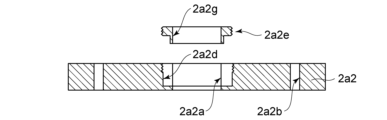
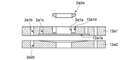
図5は、溝2a2cの形成を例示するための模式分解図である。
図5に示すように、部分2a2の孔2a2aの内壁と、部分2a2の部分2a1の側の面と、に開口する凹部2a2dを設けることができる。そして、凹部2a2dの内壁に、ピース2a2eを取り付けることで、溝2a2cを形成することができる。
FIG. 5 is a schematic exploded view for illustrating the formation of groove 2a2c.
5, a recess 2a2d can be provided that opens to the inner wall of the hole 2a2a of the portion 2a2 and to the surface of the portion 2a2 on the side of the portion 2a1. Then, a piece 2a2e can be attached to the inner wall of the recess 2a2d to form a groove 2a2c.
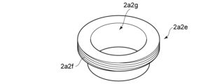
図6は、ピース2a2eを例示するための模式斜視図である。
図6に示すように、ピース2a2eの一方の端部側には、拡径部2a2fを設けることができる。拡径部2a2fの側面に雄ネジを設け、凹部2a2dの内壁に雌ネジを設けることができる。
また、ピース2a2eには中心軸方向を貫通する孔2a2gを設けることができる。ピース2a2eの孔2a2gの径寸法は、部分2a2の孔2a2aの径寸法と同じとすることができる。
FIG. 6 is a schematic perspective view illustrating piece 2a2e.
6, an enlarged diameter portion 2a2f may be provided on one end side of the piece 2a2e. A male thread may be provided on the side surface of the enlarged diameter portion 2a2f, and a female thread may be provided on the inner wall of the recess 2a2d.
The piece 2a2e may be provided with a hole 2a2g penetrating in the central axis direction. The diameter of the hole 2a2g of the piece 2a2e may be the same as the diameter of the hole 2a2a of the portion 2a2.
凹部2a2dの内壁に、ピース2a2eを取り付けることで、溝2a2cを形成すれば、溝2a2cの形成が容易となる。また、部分2a2と冷却ノズル3dとの組立作業が容易となる。
By attaching piece 2a2e to the inner wall of recess 2a2d, groove 2a2c can be formed, which makes it easier to form groove 2a2c. In addition, this makes it easier to assemble part 2a2 and cooling
図1に示すように、第1液体供給部4は、基板100の表面100bに液体101を供給する。後述する凍結工程において、液体101が液体から固体に変化(液固相変化)すると体積が変化するので圧力波が生じる。この圧力波により、基板100の表面100bに付着している汚染物が分離されると考えられる。そのため、液体101は、基板100の材料と反応し難いものであれば特に限定はない。
As shown in FIG. 1, the first liquid supply unit 4 supplies liquid 101 to the
なお、液体101を凍結した際に体積が増える液体とすれば、体積増加に伴う物理力を利用して、基板100の表面に付着している汚染物を分離できるとも考えられる。そのため、液体101は、基板100の材料と反応し難く、且つ、凍結した際に体積が増える液体とすることができる。例えば、液体101は、水(例えば、純水や超純水など)や、水を主成分とする液体などとすることができる。
If
水を主成分とする液体とする場合、水以外の成分が余り多くなると、体積増加に伴う物理力を利用することが難しくなるので、汚染物の除去率が低下するおそれがある。そのため、水以外の成分の濃度は、5wt%以上、30wt%以下とすることができる。 When using a liquid whose main component is water, if there are too many components other than water, it becomes difficult to utilize the physical force that accompanies the increase in volume, and there is a risk that the rate of removal of contaminants will decrease. Therefore, the concentration of components other than water can be set to 5 wt% or more and 30 wt% or less.
また、液体101にはガスを溶存させることができる。ガスは、例えば、炭酸ガス、オゾンガス、水素ガスなどとすることができる。 In addition, gas can be dissolved in the liquid 101. The gas can be, for example, carbon dioxide gas, ozone gas, hydrogen gas, etc.
第1液体供給部4は、例えば、液体収納部4a、供給部4b、流量制御部4c、および液体ノズル4dを有する。液体収納部4a、供給部4b、および流量制御部4cは、チャンバ6の外部に設けられている。
The first liquid supply unit 4 has, for example, a
液体収納部4aは、前述した液体101を収納する。
供給部4bは、配管を介して、液体収納部4aに接続されている。供給部4bは、液体収納部4aに収納されている液体101を液体ノズル4dに向けて供給する。供給部4bは、例えば、液体101に対する耐性を有するポンプなどとすることができる。なお、供給部4bがポンプである場合を例示したが、供給部4bはポンプに限定されるわけではない。例えば、供給部4bは、液体収納部4aの内部にガスを供給し、液体収納部4aに収納されている液体101を圧送するものとしてもよい。
The
The
流量制御部4cは、配管を介して、供給部4bに接続されている。流量制御部4cは、供給部4bにより供給される液体101の流量を制御する。流量制御部4cは、例えば、流量制御弁とすることができる。また、流量制御部4cは、液体101の供給の開始と供給の停止をも行うことができる。
The flow
液体ノズル4dは、チャンバ6の内部に設けられている。液体ノズル4dは、筒状を呈している。液体ノズル4dの一方の端部は、配管を介して、流量制御部4cに接続されている。液体ノズル4dの他方の端部は、載置台2aに載置された基板100の表面100bに対向している。そのため、液体ノズル4dから吐出した液体101は、基板100の表面100bに供給される。
The
また、液体ノズル4dの他方の端部(液体101の吐出口)は、基板100の表面100bの略中央に位置している。液体ノズル4dから吐出した液体101は、基板100の表面100bの略中央から拡がり、基板100の表面100bで略一定の厚みを有する液膜が形成される。
The other end of the
第2液体供給部5は、基板100の表面100bに液体102を供給する。第2液体供給部5は、液体収納部5a、供給部5b、流量制御部5c、および液体ノズル4dを有する。
The second
液体102は、後述する解凍工程において用いることができる。そのため、液体102は、基板100の材料と反応し難く、且つ、後述する乾燥工程において基板100の表面100bに残留し難いものであれば特に限定はない。液体102は、例えば、水(例えば、純水や超純水など)や、水を主成分とする液体とすることができる。
The liquid 102 can be used in the thawing process described below. Therefore, there are no particular limitations on the liquid 102, so long as it is unlikely to react with the material of the
液体収納部5aは、前述した液体収納部4aと同様とすることができる。供給部5bは、前述した供給部4bと同様とすることができる。流量制御部5cは、前述した流量制御部4cと同様とすることができる。
The
なお、液体102と液体101が同じである場合には、第2液体供給部5を省くことができる。また、液体ノズル4dを兼用する場合を例示したが、液体101を吐出する液体ノズルと、液体102を吐出する液体ノズルを別々に設けることもできる。
When liquid 102 and liquid 101 are the same, the second
また、液体102の温度は、液体101の凝固点よりも高い温度とすることができる。また、液体102の温度は、凍結した液体101を解凍できる温度とすることもできる。液体102の温度は、例えば、常温(20℃)程度とすることができる。
The temperature of the liquid 102 can be set to a temperature higher than the freezing point of the liquid 101. The temperature of the liquid 102 can also be set to a temperature at which the
なお、第2液体供給部5が省かれる場合には、液体101の温度は、液体101の凝固点よりも高い温度とすることができる。また、液体101の温度は、凍結した液体101を解凍できる温度とすることもできる。液体101の温度は、例えば、常温(20℃)程度とすることができる。
When the second
チャンバ6は、箱状を呈している。チャンバ6の内部にはカバー6aが設けられている。カバー6aは、基板100に供給され、基板100が回転することで基板100の外部に排出された液体101、102を受け止める。カバー6aは、筒状を呈している。カバー6aの、載置台2a側とは反対側の端部の近傍(カバー6aの上端近傍)は、カバー6aの中心に向けて屈曲している。そのため、基板100の上方に飛び散る液体101、102の捕捉が容易となる。
The
また、チャンバ6の内部には仕切り板6bが設けられている。仕切り板6bは、カバー6aの外面と、チャンバ6の内面との間に設けられている。
A
チャンバ6の底面側の側面には複数の排出口6cが設けられている。図1の場合には、排出口6cが2つ設けられている。使用済みの冷却ガス3a1、空気7a、液体101、および液体102は、排出口6cからチャンバ6の外部に排出される。排出口6cには排気管6c1が接続されている。また、排出口6cには液体101、102を排出する排出管6c2が接続されている。
排出口6cは基板100よりも下方に設けられている。そのため、冷却ガス3a1が排出口6cから排気されることでダウンフローの流れが作りだされる。その結果、パーティクルの舞い上がりを防ぐことができる。
The
平面視において、複数の排出口6cは、チャンバ6の中心に対して対称となるように設けられている。この様にすれば、チャンバ6の中心に対して、冷却ガス3a1の排気方向が対称となる。冷却ガス3a1の排気方向が対称となれば、冷却ガス3a1の排気が円滑となる。
In a plan view, the
送風部7は、チャンバ6の天井面に設けられている。なお、送風部7は、天井側であれば、チャンバ6の側面に設けることもできる。送風部7は、ファンなどの送風機とフィルタを備えることができる。フィルタは、例えば、HEPAフィルタ(High Efficiency Particulate Air Filter)などとすることができる。
The
送風部7は、仕切り板6bとチャンバ6の天井との間の空間に空気7a(外気)を供給する。そのため、仕切り板6bとチャンバ6の天井との間の空間の圧力が外部の圧力より高くなる。その結果、送風部7により供給された空気7aを排出口6cに導くことが容易となる。また、パーティクルなどの汚染物が、排出口6cからチャンバ6の内部に侵入するのを抑制することができる。
The
排気部8は、排気管6c1に接続されている。排気部8は、使用済みの冷却ガス3a1、および空気7aを排気する。排気部8は、ポンプやブロアなどとすることができる。
The exhaust unit 8 is connected to the exhaust pipe 6c1. The exhaust unit 8 exhausts the used cooling gas 3a1 and
コントローラ9は、基板処理装置1に設けられた各要素の動作を制御する。コントローラ9は、例えば、CPU(Central Processing Unit)などの演算部と、半導体メモリなどの記憶部を有する。コントローラ9は、例えば、コンピュータとすることができる。記憶部には、基板処理装置1に設けられた各要素の動作を制御する制御プログラムを格納することができる。演算部は、記憶部に格納されている制御プログラム、操作者により入力されたデータなどを用いて、基板処理装置1に設けられた各要素の動作を制御する。
The controller 9 controls the operation of each element provided in the
次に、基板処理装置1の作用について例示をする。
図7は、基板処理装置1の作用を例示するためのタイミングチャートである。
なお、図7は、基板100が6025クオーツ(Qz)基板(152mm×152mm×6.35mm)、液体101および液体102が純水の場合である。
Next, the operation of the
FIG. 7 is a timing chart illustrating the operation of the
In addition, FIG. 7 shows a case where the
まず、チャンバ6の図示しない搬入搬出口を介して、基板100がチャンバ6の内部に搬入される。搬入された基板100は、複数の保持部2eに載置され、複数の保持部2eにより、基板100の保持と、基板100の位置合わせが行われる。
First, the
図8は、基板100の受け渡しを例示するための模式断面図である。
図9は、図8における載置部2のB-B線方向の模式図である。
例えば、図示しない搬送装置から処理前の基板100を受け取る際には、図8、および図9に示すように、複数の保持部2eを回転軸2bから離れる方向に移動させる。そして、図8に示すように、図示しない昇降装置により、リフトピン2dの先端を載置台2a(部分2a1)の上方に移動させて、図示しない搬送装置から処理前の基板100を受け取る。次に、図示しない昇降装置によりリフトピン2dを下降させて、処理前の基板100を保持部2eに受け渡す。この場合、図1、および図2に示すように、下降端において、リフトピン2dの先端が載置台2a(部分2a2)の下方に位置するようにする。この様にすれば、載置台2aの回転が可能となる。次に、図2および図3に示すように、複数の保持部2eを回転軸2bに向かって移動させる。そして、複数の保持部2eにより、基板100の保持と、基板100の位置合わせを行う。
FIG. 8 is a schematic cross-sectional view illustrating the transfer of the
FIG. 9 is a schematic diagram of the mounting
For example, when receiving the
複数の保持部2eに基板100が保持された後に、図7に示すように予備工程、液膜の形成工程、冷却工程(過冷却工程+凍結工程)、解凍工程、乾燥工程を含む凍結洗浄工程が行われる。
After the
まず、図7に示すように予備工程が実行される。予備工程においては、コントローラ9が、供給部4bおよび流量制御部4cを制御して、基板100の表面100bに、所定の流量の液体101を供給する。また、コントローラ9が、流量制御部3cを制御して、基板100の裏面100aに、所定の流量の冷却ガス3a1を供給する。また、コントローラ9が、駆動部2cを制御して、基板100を所定の回転数(第2の回転数)で回転させる。
この場合、液体101が、回転する基板100に供給され続ける状態となる。
First, a preliminary process is performed as shown in Fig. 7. In the preliminary process, the controller 9 controls the
In this case, the liquid 101 continues to be supplied to the
ここで、冷却部3による冷却ガス3a1の供給によりチャンバ6内の雰囲気が冷やされると、空気中のダストを含んだ霜が基板100に付着し、汚染の原因となるおそれがある。予備工程においては、基板100の表面100bに液体101を供給し続けているので、基板100を均一に冷却しつつ、基板100の表面100bへの霜の付着を防止することができる。
Here, if the atmosphere in the
例えば、図7に例示したものの場合には、第2の回転数を、例えば、50rpm~500rpm程度、液体101の流量を0.1L/min~1L/min程度、冷却ガス3a1の流量を40NL/min~200NL/min程度、予備工程の工程時間を1800秒程度とすることができる。なお、予備工程の工程時間は、基板100の面内温度が略均一となる時間であればよい。これらの条件は、予め実験やシミュレーションを行うことで求めることができる。
For example, in the example shown in FIG. 7, the second rotation speed can be, for example, about 50 rpm to 500 rpm, the flow rate of the liquid 101 can be about 0.1 L/min to 1 L/min, the flow rate of the cooling gas 3a1 can be about 40 NL/min to 200 NL/min, and the process time of the preliminary process can be about 1800 seconds. Note that the process time of the preliminary process may be any time that allows the in-plane temperature of the
予備工程における基板100の表面100bの液体101の温度は、液体101が供給され続けている状態であるため、供給される液体101の温度とほぼ同じとなる。例えば、供給される液体101の温度が常温(20℃)程度である場合、基板100の表面100bに存在する液体101(以下、液膜という)の温度は常温(20℃)程度となる。
The temperature of the liquid 101 on the
次に、図7に示すように液膜の形成工程が実行される。液膜の形成工程においては、予備工程において供給されていた液体101の供給を停止する。この場合、基板100の回転が維持されているので、基板100の表面100bにある液体101が排出される。そして、基板100の回転数を第2の回転数より遅い第1の回転数まで減速させる。第1の回転数は、例えば、0~50rpmの範囲とすればよい。基板100の回転数を第1の回転数とした後に、所定の量の液体101を基板100に供給して液膜を形成する。なお、冷却ガス3a1の供給は、維持されている。
Next, the liquid film forming process is performed as shown in FIG. 7. In the liquid film forming process, the supply of the liquid 101 that was supplied in the preliminary process is stopped. In this case, since the rotation of the
液膜の形成工程において形成される液膜の厚み(過冷却工程を行う際の液膜の厚み)は、200~1300μm程度とすることができる。例えば、コントローラ9は、液体101の供給量を制御して、基板100の表面100bの上にある液膜の厚みを200~1300μm程度にする。
The thickness of the liquid film formed in the liquid film formation process (the thickness of the liquid film when the supercooling process is performed) can be about 200 to 1300 μm. For example, the controller 9 controls the supply amount of the liquid 101 to make the thickness of the liquid film on the
次に、図7に示すように冷却工程(過冷却工程+凍結工程)が実行される。なお、本実施の形態では、冷却工程のうち、液体101が過冷却状態となってから凍結が始まるまでの工程を「過冷却工程」、過冷却状態の液体101が凍結状態となり、解凍工程により解凍が始まるまでを「凍結工程」と称する。
Next, the cooling process (supercooling process + freezing process) is carried out as shown in FIG. 7. In this embodiment, the cooling process from when the liquid 101 becomes supercooled to when freezing begins is called the "supercooling process," and the process from when the supercooled
ここで、液体101の冷却速度が余り速くなると液体101が過冷却状態とならず、すぐに凍結してしまう。そのため、コントローラ9は、冷却ガス3a1の流量、および、基板100の回転数の少なくともいずれかを制御することで、基板100の表面100bの液体101が過冷却状態となるようにする。
Here, if the cooling speed of the liquid 101 becomes too fast, the liquid 101 will not reach a supercooled state and will immediately freeze. Therefore, the controller 9 controls at least one of the flow rate of the cooling gas 3a1 and the rotation speed of the
液体101が過冷却状態となる条件は、基板100の大きさ、液体101の粘度、冷却ガス3a1の比熱などの影響を受ける。そのため、液体101が過冷却状態となる条件は、実験やシミュレーションを行うことで適宜決定することができる。
The conditions under which the liquid 101 becomes supercooled are affected by the size of the
図7に例示するように、冷却工程(過冷却工程+凍結工程)においては、冷却ガス3a1の流量および回転数は、液膜の形成工程と同じである。基板100の裏面100aに供給され続けている冷却ガス3a1により、基板100上の液膜の温度が、液膜の形成工程における液膜の温度よりもさらに下がり、過冷却状態となる。
As illustrated in FIG. 7, in the cooling process (supercooling process + freezing process), the flow rate and rotation speed of the cooling gas 3a1 are the same as in the liquid film formation process. The cooling gas 3a1 that continues to be supplied to the
過冷却状態においては、例えば、液膜の温度、パーティクルなどの汚染物の存在、振動などにより、液体101の凍結が開始する。例えば、パーティクルなどの汚染物が存在する場合、液体101の温度が、-20℃から-35℃程度になると液体101の凍結が開始する。 In a supercooled state, the liquid 101 begins to freeze due to, for example, the temperature of the liquid film, the presence of contaminants such as particles, vibration, etc. For example, if contaminants such as particles are present, the liquid 101 begins to freeze when the temperature of the liquid 101 falls to approximately -20°C to -35°C.
過冷却状態の液体101の凍結が開始すると、過冷却工程から凍結工程に移行する。
凍結工程においては、基板100の表面100bの液膜の少なくとも一部を凍結させる。本実施の形態に係る凍結洗浄工程では、液膜が完全に凍結して氷膜となる場合を説明する。
When the supercooled liquid 101 starts to freeze, the process moves from the supercooling process to the freezing process.
In the freezing step, at least a part of the liquid film on the
次に、図7に示すように解凍工程が実行される。なお、図7に例示をしたものは、液体101と液体102が同じ液体の場合である。そのため、図7では液体101と記載している。解凍工程においては、コントローラ9が、供給部4bおよび流量制御部4cを制御して、基板100の表面100bに、所定の流量の液体101を供給する。なお、液体101と液体102が異なる場合には、コントローラ9が、供給部5bおよび流量制御部5cを制御して、基板100の表面100bに、所定の流量の液体102を供給する。
Next, the thawing process is carried out as shown in FIG. 7. Note that the example shown in FIG. 7 shows a case where liquid 101 and liquid 102 are the same liquid. Therefore, liquid 101 is described in FIG. 7. In the thawing process, the controller 9 controls the
また、コントローラ9が、流量制御部3cを制御して、冷却ガス3a1の供給を停止させる。これにより氷膜の解凍が始まり、氷膜は徐々に液体101となってゆく。また、コントローラ9が、駆動部2cを制御して、基板100の回転数を第2の回転数よりも速い第3の回転数へと増加させる。基板100の回転が速くなれば、液体101と、氷膜の溶け残りと、を遠心力で振り切ることができる。そのため、液体101と、氷膜の溶け残りと、を基板100の表面100bから排出することができる。この際、基板100の表面100bから分離された汚染物も、これらとともに排出される。
The controller 9 also controls the
なお、液体101または液体102の供給量は、解凍ができるのであれば特に限定はない。また、第3の回転数は、液体101、氷膜の溶け残り、および汚染物が排出できるのであれば特に限定はない。
The amount of
次に、図7に示すように乾燥工程が実行される。乾燥工程においては、コントローラ9が、供給部4bおよび流量制御部4cを制御して、液体101の供給を停止させる。なお、液体101と液体102が異なる液体の場合には、コントローラ9が、供給部5bおよび流量制御部5cを制御して、液体102の供給を停止させる。
Next, the drying process is carried out as shown in FIG. 7. In the drying process, the controller 9 controls the
また、コントローラ9が、駆動部2cを制御して、基板100の回転数を、第3の回転数よりも速い第4の回転数にする。基板100の回転が速くなれば、基板100の乾燥を迅速に行うことができる。なお、第4の回転数は、乾燥ができるのであれば特に限定はない。
以上の様にすることで、基板100の処理(汚染物の除去)を行うことができる。
Furthermore, the controller 9 controls the driving
In this manner, the
次に、複数の保持部2eに保持されている処理済みの基板100を、図示しない搬送装置に受け渡す。図示しない搬送装置は、処理済みの基板100をチャンバ6の外部に搬出する。
Next, the processed
例えば、図8、および図9に示すように、複数の保持部2eを回転軸2bから離れる方向に移動させる。そして、図8に示すように、図示しない昇降装置により、リフトピン2dの先端を載置台2a(部分2a1)の上方に移動させて、複数の保持部2eから処理済みの基板100を受け取り、受け取った処理済みの基板100を、図示しない搬送装置に受け渡す。その後、図1、および図2に示すように、リフトピン2dを下降端まで下降させる。
以降、前述した手順を繰り返すことで、複数の基板100の凍結洗浄処理を行うことができる。
For example, as shown in Figures 8 and 9, the multiple holding
Thereafter, the above-mentioned procedure is repeated to perform the freeze cleaning process on a plurality of
図10は、他の実施形態に係る載置部12を例示するための模式断面図である。
図10に示すように、載置部12は、載置台12a、回転軸2b、駆動部2c、リフトピン2d、および保持部2eを有する。
なお、図10においては、駆動部2cは、省略している。
FIG. 10 is a schematic cross-sectional view illustrating a mounting
As shown in FIG. 10, the mounting
In addition, the driving
載置台12aは、例えば、部分12a1(第2の部分の一例に相当する)、および部分12a2(第1の部分の一例に相当する)を有する。
部分12a1は、前述した部分2a1に、凹部12a1aと溝12a1b(第2の溝の一例に相当する)をさらに設けたものである。シール部3d1の、基部3d1aの周縁近傍および凸部3d1bは、隙間(第3の隙間の一例に相当する)を介して溝12a1bに設けられている。凹部12a1aは、孔2a1aの内壁と、部分12a1の、部分12a2側の面に開口している。凹部12a1aの底面には、冷却ガス3a1を排出するための孔2a1cが開口している。なお、凹部12a1aは、部分12a2に設けられていてもよい。
The mounting table 12a has, for example, a portion 12a1 (corresponding to an example of a second portion) and a portion 12a2 (corresponding to an example of a first portion).
The portion 12a1 is obtained by further providing a recess 12a1a and a groove 12a1b (corresponding to an example of a second groove) to the above-mentioned portion 2a1. The vicinity of the periphery of the base 3d1a and the protrusion 3d1b of the seal portion 3d1 are provided in the groove 12a1b via a gap (corresponding to an example of a third gap). The recess 12a1a opens to the inner wall of the hole 2a1a and to the surface of the portion 12a1 on the portion 12a2 side. A hole 2a1c for discharging the cooling gas 3a1 is opened in the bottom surface of the recess 12a1a. The recess 12a1a may be provided in the portion 12a2.
部分12a2は、前述した部分2a2から溝2a2cを削除し、部分12a2の部分12a1側の面に傾斜面をさらに設けたものである。なお、傾斜面は省くこともできる。 The portion 12a2 is obtained by removing the groove 2a2c from the portion 2a2 described above, and by providing an inclined surface on the surface of the portion 12a2 facing the portion 12a1. The inclined surface may be omitted.
前述した、載置台2aの場合は、第1の部分2a1と第2の部分2a2との間に設けられた隙間を、冷却ガス3a1を排出するための流路2a3としている。これに対して、載置台12aの場合には、凹部12a1aを、冷却ガス3a1を排出するための流路12a3としている。そのため、載置部12の場合には、部分12a2の孔2a2aを介して、チャンバ6の底面側に冷却ガス3a1が排出される。
すなわち、流路12a3は、載置台12aの外部とは繋がらず、冷却ノズル3dと、部分2a1の孔2a1aおよび部分2a2の孔2a2aとの間の隙間に繋がっている。
孔2a1cは、流路12a3と、載置台12a(部分12a1)と基板100との間の空間と、に繋がっている。
In the case of the mounting table 2a described above, the gap between the first portion 2a1 and the second portion 2a2 serves as the flow path 2a3 for discharging the cooling gas 3a1. In contrast, in the case of the mounting table 12a, the recess 12a1a serves as the flow path 12a3 for discharging the cooling gas 3a1. Therefore, in the case of the mounting
That is, the flow path 12a3 is not connected to the outside of the mounting table 12a, but is connected to the gap between the cooling
Hole 2a1c is connected to flow path 12a3 and the space between mounting table 12a (portion 12a1) and
また、シール部3d1と、部分12a1に設けられた溝12a1bとにより、冷却ノズル3dから吐出した冷却ガス3a1が、孔2a1aの開口に侵入するのが抑制される。そのため、基板100の冷却に寄与しない冷却ガス3a1が生じるのを抑制することができる。
In addition, the sealing portion 3d1 and the groove 12a1b provided in the portion 12a1 prevent the cooling gas 3a1 discharged from the cooling
図11は、溝12a1bの形成を例示するための分解図である。
図11に示すように、部分12a1の孔2a1aの内壁と、部分12a1の基板100の側の面と、に開口する凹部12a1dを設けることができる。そして、凹部12a1dの内壁に、ピース2a2eを取り付けることで、溝12a1bを形成することができる。
FIG. 11 is an exploded view for illustrating the formation of the groove 12a1b.
11, a recess 12a1d can be provided that opens to the inner wall of hole 2a1a of portion 12a1 and to the surface of portion
凹部12a1dの内壁に、ピース2a2eを取り付けることで、溝12a1bを形成すれば、溝12a1bの形成が容易となる。また、部分12a1と冷却ノズル3dとの組立作業が容易となる。
By attaching piece 2a2e to the inner wall of recess 12a1d, groove 12a1b can be formed, which makes it easier to form groove 12a1b. In addition, this makes it easier to assemble part 12a1 and
図12は、他の実施形態に係る載置部を例示するための模式断面図である。
図13は、図12における載置部のC-C線方向の模式図である。
図14は、保持部を例示するための模式斜視図である。
図12に示すように、載置部22は、載置台22a、回転軸2b、駆動部2c、リフトピン2d、および保持部22eを有する。
なお、図12においては、回転軸2b、および駆動部2cは、省略している。
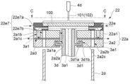
FIG. 12 is a schematic cross-sectional view for illustrating a mounting portion according to another embodiment.
FIG. 13 is a schematic diagram of the placement portion in FIG. 12 taken along line CC.
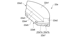
FIG. 14 is a schematic perspective view for illustrating the holding portion.
As shown in FIG. 12, the mounting
In FIG. 12, the
載置台22aは、例えば、部分22a1(第2の部分の一例に相当する)、および部分2a2(第1の部分の一例に相当する)を有する。
部分22a1は、前述した部分2a1と同様とすることができる。ただし、孔2a1c(第2の孔の一例に相当する)は、孔2a1bよりも部分22a1の周縁側に設けられている。
The mounting table 22a has, for example, a portion 22a1 (corresponding to an example of a second portion) and a portion 2a2 (corresponding to an example of a first portion).
The portion 22a1 may be similar to the portion 2a1 described above, except that the hole 2a1c (corresponding to an example of a second hole) is provided closer to the periphery of the portion 22a1 than the hole 2a1b.
図12、および図13に示すように、保持部22eは、基板100を保持する。
図14に示すように、保持部22eは、板状を呈し、上面22e1、側面22e2、内側面22e3、支持面22e4、内周面22e5、および下面22e6を有する。
上面22e1は、例えば、前述した保持部2eの上面2e1と同様とすることができる。 側面22e2は、例えば、前述した保持部2eの側面2e2と同様とすることができる。
内側面22e3は、例えば、前述した保持部2eの内側面2e3と同様とすることができる。
支持面22e4は、基板100の周縁近傍を支持する。この場合、支持面22e4は、斜面とすることもできる。支持面22e4を斜面とする場合には、支持面22e4は、載置台22a(部分22a1)の面(基板100の裏面100a)に対して傾斜させることができる。例えば、支持面22e4と、載置台22a(部分22a1)の面との間の距離が、内側面22e3側になるに従い漸増するようにすることができる。例えば、支持面22e4は、前述した保持部2eの斜面2e4と同様とすることができる。支持面22e4が斜面となっていれば、基板100の裏面100aと支持面22e4とを線接触させることができる。そのため、基板100の裏面100aに損傷が発生するのを抑制することができる。
内周面22e5は、支持面22e4の、内側面2e3側とは反対側の端部に接続されている。内周面22e5は、支持面22e4の下方に設けられている。例えば、内周面22e5は、内側面2e3と平行な平坦面とすることができる。
下面22e6は、上面22e1と対向している。下面22e6は、上面22e1と平行な平坦面とすることができる。
As shown in FIGS. 12 and 13, the holding
As shown in FIG. 14, the holding
The upper surface 22e1 may be, for example, similar to the upper surface 2e1 of the holding
The inner surface 22e3 may be, for example, similar to the inner surface 2e3 of the holding
The support surface 22e4 supports the vicinity of the periphery of the
The inner circumferential surface 22e5 is connected to an end of the support surface 22e4 opposite to the inner surface 2e3. The inner circumferential surface 22e5 is provided below the support surface 22e4. For example, the inner circumferential surface 22e5 may be a flat surface parallel to the inner surface 2e3.
The lower surface 22e6 faces the upper surface 22e1. The lower surface 22e6 may be a flat surface parallel to the upper surface 22e1.
また、両側の側面22e2のそれぞれには、流路22e7を設けることができる。例えば、保持部22eは、前述した保持部2eに、流路22e7をさらに設けたものとすることができる。
流路22e7は、溝22e7a、および孔22e7bを有する。溝22e7aは、保持部22eの側面22e2と内周面22e5とに開口している。孔22e7bは、保持部22eの下面22e6と溝22e7aの内壁とに開口している。
図13に示すように、複数の保持部22eにより、基板100を保持した際には、保持部22eに設けられた溝22e7aが、隣接する保持部22eに設けられた溝22e7aと接続される。また、保持部22eに設けられた孔22e7bが、隣接する保持部22eに設けられた孔22e7bと接続される。この場合、保持部22eに設けられた孔22e7bと、隣接する保持部22eに設けられた孔22e7bとが、部分22a1に設けられた孔2a1cの上方に位置するようにすることができる。
In addition, a flow path 22e7 may be provided in each of the side surfaces 22e2 on both sides. For example, the holding
The flow passage 22e7 has a groove 22e7a and a hole 22e7b. The groove 22e7a opens to the side surface 22e2 and the inner circumferential surface 22e5 of the holding
13, when the
そのため、図12に示すように、複数の保持部22eにより、基板100を保持した際には、載置台22a(部分22a1)と基板100との間の空間に供給された冷却ガス3a1が、溝22e7a、孔22e7b、孔2a1c、および部分22a1と部分2a2との間の隙間を介して、載置部22(載置台22a)の外側に排出される。
Therefore, as shown in FIG. 12, when the
図13に示すように、流路22e7が設けられていれば、孔2a1cを部分22a1の周縁近傍であって、基板100の四隅周辺に設けることができる。そのため、載置台22a(部分22a1)と基板100との間の空間に供給された冷却ガス3a1を、基板100の四隅周辺に集中させることができる。また、流路22e7を介して孔2a1cに冷却ガス3a1を流すことで、基板100の四隅周辺に冷却ガス3a1を集めることができる。また、基板100の四隅周辺における冷却ガス3a1の流れを活発にすることができる。そのため、基板100の四隅周辺を効率的に冷却することができる。
また、載置台22aの内部を冷却ガス3a1が通過するため、載置台22aも冷却される。そのため、載置台22aを介して基板100を冷却することができるので、基板100の冷却が容易となる。
この場合、図13に示すように、溝22e7aは、載置台22aの中心から、基板100の四隅に向かう方向と平行となるようにすることが好ましい。
また、複数の保持部22eにより、基板100を保持した際には、リフトピン2dが挿通する孔2a1bが、複数の保持部22eにより塞がれるようにすることが好ましい。この様にすれば、載置台22a(部分22a1)と基板100との間の空間に供給された冷却ガス3a1が、孔2a1bを介して排出されるのを抑制することができる。そのため、基板100の四隅周辺に冷却ガス3a1を供給するのが容易となる。
As shown in FIG. 13, if the flow path 22e7 is provided, the holes 2a1c can be provided near the periphery of the portion 22a1 and around the four corners of the
In addition, since the cooling gas 3a1 passes through the inside of the mounting table 22a , the mounting table 22a is also cooled. Therefore, the
In this case, as shown in FIG. 13, it is preferable that the grooves 22e7a are parallel to the direction from the center of the mounting table 22a toward the four corners of the
In addition, when the
図15は、他の実施形態に係る載置部を例示するための模式断面図である。
図16は、図15における載置部のD-D線方向の模式図である。
図17は、保持部を例示するための模式斜視図である。
図15に示すように、載置部32は、載置台32a、回転軸2b、駆動部2c、リフトピン2d、および保持部32eを有する。
なお、図15においては、回転軸2b、および駆動部2cは、省略している。
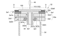
FIG. 15 is a schematic cross-sectional view for illustrating a mounting portion according to another embodiment.
FIG. 16 is a schematic diagram of the placement portion in FIG. 15 taken along line DD.
FIG. 17 is a schematic perspective view for illustrating the holding portion.
As shown in FIG. 15, the mounting
In FIG. 15, the
載置台32aは、例えば、部分32a1(第2の部分の一例に相当する)、および部分2a2(第1の部分の一例に相当する)を有する。
部分32a1は、前述した部分2a1と同様とすることができる。ただし、部分32a1には、孔2a1cが設けられていない。
The mounting table 32a has, for example, a portion 32a1 (corresponding to an example of the second portion) and a portion 32a2 (corresponding to an example of the first portion).
The portion 32a1 may be similar to the portion 2a1 described above, except that the portion 32a1 does not include the hole 2a1c.
図15、および図16に示すように、保持部32eは、基板100を保持する。
図17に示すように、保持部32eは、板状を呈し、上面32e1、側面32e2、内側面32e3、支持面32e4、内周面32e5、下面32e6、および外周面32e7を有する。
上面32e1は、例えば、前述した保持部22eの上面22e1と同様とすることができる。
側面32e2は、例えば、前述した保持部22eの側面22e2と同様とすることができる。
内側面32e3は、例えば、前述した保持部22eの内側面22e3と同様とすることができる。
支持面32e4は、例えば、前述した保持部22eの支持面22e4と同様とすることができる。
内周面32e5は、例えば、前述した保持部22eの内周面22e5と同様とすることができる。
下面32e6は、例えば、前述した保持部22eの下面22e6と同様とすることができる。
外周面32e7は、内側面32e3および内周面32e5と対向している。外周面32e7の一方の端部は、上面32e1の、内側面32e3側とは反対側の周縁に接続されている。外周面32e7の他方の端部は、下面32e6の、内周面32e5側とは反対側の周縁に接続されている。
As shown in FIGS. 15 and 16, the holding
As shown in FIG. 17, the holding
The upper surface 32e1 can be, for example, similar to the upper surface 22e1 of the holding
The side surface 32e2 may be similar to the side surface 22e2 of the holding
The inner surface 32e3 may be similar to the inner surface 22e3 of the holding
The support surface 32e4 may be, for example, similar to the support surface 22e4 of the holding
The inner circumferential surface 32e5 may be similar to the inner circumferential surface 22e5 of the holding
The lower surface 32e6 may be similar to the lower surface 22e6 of the holding
The outer peripheral surface 32e7 faces the inner peripheral surface 32e3 and the inner peripheral surface 32e5. One end of the outer peripheral surface 32e7 is connected to the periphery of the upper surface 32e1 on the opposite side to the inner peripheral surface 32e3. The other end of the outer peripheral surface 32e7 is connected to the periphery of the lower surface 32e6 on the opposite side to the inner peripheral surface 32e5.
また、両側の側面32e2のそれぞれには、流路32e8を設けることができる。例えば、保持部32eは、前述した保持部22eの流路22e7を流路32e8に代えたものとすることができる。
図16、および図17に示すように、流路32e8は、側面32e2、内周面32e5、および外周面32e7に開口している。
図16に示すように、複数の保持部32eにより、基板100を保持した際には、保持部32eに設けられた流路32e8が、隣接する保持部32eに設けられた流路32e8と接続される。
In addition, a flow path 32e8 may be provided in each of the side surfaces 32e2 on both sides. For example, the holding
As shown in FIGS. 16 and 17, the flow passage 32e8 opens to the side surface 32e2, the inner peripheral surface 32e5, and the outer peripheral surface 32e7.
As shown in FIG. 16, when the
そのため、図15に示すように、複数の保持部32eにより、基板100を保持した際には、載置台32a(部分32a1)と基板100との間の空間に供給された冷却ガス3a1が、流路32e8を介して、載置部32(載置台32a)の外側に排出される。
図16に示すように、流路32e8が設けられていれば、載置台32a(部分32a1)と基板100との間の空間に供給された冷却ガス3a1を、基板100の四隅周辺に集めることができる。また、基板100の四隅周辺における冷却ガス3a1の流れを活発にすることができる。そのため、基板100の四隅周辺を効率的に冷却することができる。
この場合、図15に示すように、流路32e8は、載置台32aの中心から、基板100の四隅に向かう方向と平行となるようにすることが好ましい。
また、複数の保持部32eにより、基板100を保持した際には、リフトピン2dが挿通する孔2a1bが、複数の保持部32eにより塞がれるようにすることが好ましい。この様にすれば、載置台32a(部分32a1)と基板100との間の空間に供給された冷却ガス3a1が、孔2a1bを介して排出されるのを抑制することができる。そのため、基板100の四隅周辺に冷却ガス3a1を供給するのが容易となる。
Therefore, as shown in FIG. 15, when the
16, if the flow path 32e8 is provided, the cooling gas 3a1 supplied to the space between the mounting table 32a (part 32a1) and the
In this case, as shown in FIG. 15, it is preferable that the flow path 32e8 is parallel to the direction from the center of the mounting table 32a toward the four corners of the
In addition, when the
すなわち、本実施の形態に係る載置部32としても、前述した載置部22と同様の効果を享受することができる。
ここで、前述した様に、単に、冷却ガス3a1が基板100の外側に流れると、凍結洗浄処理を行う雰囲気に含まれている水分により、基板100の周縁近傍に霜が発生するおそれがある。
しかしながら、図17に示すように、流路32e8は、外周面32e7に開口している。そのため、図15に示すように、冷却ガス3a1が載置部32の外側に排出される位置を、基板100の周縁から離すことができる。冷却ガス3a1が載置部32の外側に排出される位置が基板100の周縁から離れていれば、凍結洗浄処理を行う雰囲気に含まれている水分により、基板100の周縁近傍に霜が発生するのを抑制することができる。
That is, the
Here, as described above, if the cooling gas 3a1 simply flows to the outside of the
However, as shown in Fig. 17, the flow path 32e8 opens to the outer circumferential surface 32e7. Therefore, as shown in Fig. 15, the position where the cooling gas 3a1 is discharged to the outside of the mounting
以上、実施の形態について例示をした。しかし、本発明はこれらの記述に限定されるものではない。前述した実施形態に関して、当業者が適宜、構成要素の追加、削除若しくは設計変更を行ったもの、または、工程の追加、省略若しくは条件変更を行ったものも、本発明の特徴を備えている限り、本発明の範囲に包含される。 The above are examples of embodiments. However, the present invention is not limited to these descriptions. Regarding the above-mentioned embodiments, those skilled in the art who appropriately add or remove components or modify the design, or add or omit processes or change conditions, are also included within the scope of the present invention as long as they have the characteristics of the present invention.
例えば、基板処理装置1が備える各要素の形状、寸法、数、配置などは、例示をしたものに限定されるわけではなく適宜変更することができる。
また、以上においては、基板100の平面形状が四角形の場合を例示したが、基板100の平面形状が円形などの場合も同様とすることができる。
For example, the shape, size, number, arrangement, etc. of each element included in the
In the above, the planar shape of the
1 基板処理装置、2 載置部、2a 載置台、2a1 部分、2a2 部分、2a2c 溝、2a3 流路、12a3 流路、2e 保持部、3 冷却部、3a1 冷却ガス、3d 冷却ノズル、3d1 シール部、3d1a 基部、 3d1b 凸部、4 第1液体供給部、5 第2液体供給部、6 チャンバ、9 コントローラ、100 基板、100a 裏面、100b 表面、101 液体、102 液体 1 Substrate processing apparatus, 2 Placement section, 2a Placement table, 2a1 Part, 2a2 Part, 2a2c Groove, 2a3 Flow path, 12a3 Flow path, 2e Holder, 3 Cooling section, 3a1 Cooling gas, 3d Cooling nozzle, 3d1 Sealing section, 3d1a Base, 3d1b Convex section, 4 First liquid supply section, 5 Second liquid supply section, 6 Chamber, 9 Controller, 100 Substrate, 100a Back surface, 100b Front surface, 101 Liquid, 102 Liquid
Claims (8)
前記載置台に設けられ、基板を保持する複数の保持部と、
前記載置台と前記基板との間の空間に、冷却ガスを供給可能な冷却部と、
前記基板の、前記載置台側とは反対側の面に液体を供給可能な液体供給部と、
を備え、
前記基板を保持する際には、前記複数の保持部のそれぞれは、前記載置台の面に沿って、前記中心軸に向かう方向に移動して、前記基板の周縁、および、前記載置台と前記基板との間の空間を囲み、前記空間が、前記複数の保持部により閉鎖される基板処理装置。 A mounting table that is rotatable around a central axis;
a plurality of holders provided on the mounting table for holding substrates;
a cooling unit capable of supplying a cooling gas to a space between the mounting table and the substrate;
a liquid supply unit capable of supplying liquid to a surface of the substrate opposite to the mounting table side;
Equipped with
When holding the substrate, each of the multiple holding parts moves along the surface of the mounting table in a direction toward the central axis to surround the edge of the substrate and the space between the mounting table and the substrate, and the space is closed by the multiple holding parts .
前記第1の部分と、前記第2の部分と、の間には、前記載置台と前記基板との間の空間に供給された前記冷却ガスを、前記載置台の外部に排出する流路が設けられている請求項1記載の基板処理装置。 The mounting table has a first portion having a plate shape and a second portion having a plate shape and provided on the first portion,
2. The substrate processing apparatus according to claim 1, further comprising a flow path provided between the first portion and the second portion for discharging the cooling gas supplied to the space between the stage and the substrate to the outside of the stage.
前記第1の部分は、厚み方向を貫通し、前記第1の孔と同芯に設けられた第3の孔を有し、
前記冷却部は、筒状を呈し、前記第1の孔および前記第3の孔に第1の隙間を介して設けられた冷却ノズルを有し、
前記流路は、前記載置台の外部と、前記第1の隙間と、に繋がり、
前記第2の孔は、前記流路と、前記載置台と前記基板との間の空間と、に繋がっている請求項2記載の基板処理装置。 the second portion has a first hole and a second hole penetrating in a thickness direction;
the first portion has a third hole penetrating the thickness direction and provided concentrically with the first hole,
the cooling portion has a cylindrical shape and includes a cooling nozzle provided in the first hole and the third hole with a first gap therebetween;
the flow path is connected to an outside of the mounting table and to the first gap,
3. The substrate processing apparatus according to claim 2, wherein the second hole is connected to the flow path and a space between the stage and the substrate.
環状を呈し、前記基部の周縁近傍に設けられた凸部と、
をさらに備え、
前記第1の部分の前記第3の孔の内壁には、第1の溝が設けられ、
前記基部の周縁近傍、および前記凸部は、第2の隙間を介して前記第1の溝に設けられている請求項3記載の基板処理装置。 A plate-shaped base portion provided on an outer surface of the cooling nozzle;
A convex portion having an annular shape and provided near the periphery of the base portion;
Further equipped with
a first groove is provided on an inner wall of the third hole of the first portion;
The substrate processing apparatus according to claim 3 , wherein the vicinity of the periphery of the base and the protrusion are provided in the first groove with a second gap therebetween.
前記第1の部分は、厚み方向を貫通し、前記第1の孔と同芯に設けられた第3の孔を有し、
前記冷却部は、筒状を呈し、前記第1の孔および前記第3の孔に第1の隙間を介して設けられた冷却ノズルを有し、
前記流路は、前記載置台の外部とは繋がらず、前記第1の隙間と繋がり、
前記第2の孔は、前記流路と、前記載置台と前記基板との間の空間と、に繋がっている請求項2記載の基板処理装置。 the second portion has a first hole and a second hole penetrating in a thickness direction;
the first portion has a third hole penetrating the thickness direction and provided concentrically with the first hole,
the cooling portion has a cylindrical shape and includes a cooling nozzle provided in the first hole and the third hole with a first gap therebetween;
the flow path is not connected to an outside of the mounting table but is connected to the first gap,
3. The substrate processing apparatus according to claim 2, wherein the second hole is connected to the flow path and a space between the stage and the substrate.
環状を呈し、前記基部の周縁近傍に設けられた凸部と、
をさらに備え、
前記第2の部分の前記第1の孔の内壁には、第2の溝が設けられ、
前記基部の周縁近傍、および前記凸部は、第3の隙間を介して前記第2の溝に設けられている請求項5記載の基板処理装置。 A plate-shaped base portion provided on an outer surface of the cooling nozzle;
A convex portion having an annular shape and provided near the periphery of the base portion;
Further equipped with
a second groove is provided on an inner wall of the first hole of the second portion;
The substrate processing apparatus according to claim 5 , wherein the vicinity of the periphery of the base and the protrusion are provided in the second groove with a third gap therebetween.
Priority Applications (5)
| Application Number | Priority Date | Filing Date | Title |
|---|---|---|---|
| CN202310114890.8A CN116666298A (en) | 2022-02-28 | 2023-02-15 | Substrate processing equipment |
| TW112105654A TWI886442B (en) | 2022-02-28 | 2023-02-17 | Substrate processing equipment |
| US18/114,377 US12472534B2 (en) | 2022-02-28 | 2023-02-27 | Substrate processing apparatus |
| KR1020230026765A KR102810048B1 (en) | 2022-02-28 | 2023-02-28 | Substrate processing apparatus |
| JP2024190741A JP2025003744A (en) | 2022-02-28 | 2024-10-30 | Substrate Processing Equipment |
Applications Claiming Priority (2)
| Application Number | Priority Date | Filing Date | Title |
|---|---|---|---|
| JP2022029357 | 2022-02-28 | ||
| JP2022029357 | 2022-02-28 |
Related Child Applications (1)
| Application Number | Title | Priority Date | Filing Date |
|---|---|---|---|
| JP2024190741A Division JP2025003744A (en) | 2022-02-28 | 2024-10-30 | Substrate Processing Equipment |
Publications (2)
| Publication Number | Publication Date |
|---|---|
| JP2023126143A JP2023126143A (en) | 2023-09-07 |
| JP7581393B2 true JP7581393B2 (en) | 2024-11-12 |
Family
ID=87887038
Family Applications (1)
| Application Number | Title | Priority Date | Filing Date |
|---|---|---|---|
| JP2023008307A Active JP7581393B2 (en) | 2022-02-28 | 2023-01-23 | Substrate Processing Equipment |
Country Status (1)
| Country | Link |
|---|---|
| JP (1) | JP7581393B2 (en) |
Citations (8)
| Publication number | Priority date | Publication date | Assignee | Title |
|---|---|---|---|---|
| JP2009514208A (en) | 2005-10-26 | 2009-04-02 | セメス カンパニー リミテッド | Spin chuck |
| JP2009105367A (en) | 2007-10-22 | 2009-05-14 | Semes Co Ltd | Wafer spin chuck and etching apparatus equipped with spin chuck |
| JP2013074243A (en) | 2011-09-29 | 2013-04-22 | Shibaura Mechatronics Corp | Substrate processing apparatus and substrate processing method |
| JP2016189452A (en) | 2015-03-27 | 2016-11-04 | 株式会社Screenホールディングス | Substrate holding method and substrate processing apparatus |
| JP2018026436A (en) | 2016-08-09 | 2018-02-15 | 芝浦メカトロニクス株式会社 | Substrate processing apparatus and substrate processing method |
| JP2020080350A (en) | 2018-11-12 | 2020-05-28 | キオクシア株式会社 | Substrate processing equipment |
| JP2021163956A (en) | 2020-03-31 | 2021-10-11 | 芝浦メカトロニクス株式会社 | Substrate processing apparatus |
| JP2022082051A (en) | 2020-11-20 | 2022-06-01 | 株式会社東芝 | Cooling device and substrate processing apparatus |
-
2023
- 2023-01-23 JP JP2023008307A patent/JP7581393B2/en active Active
Patent Citations (8)
| Publication number | Priority date | Publication date | Assignee | Title |
|---|---|---|---|---|
| JP2009514208A (en) | 2005-10-26 | 2009-04-02 | セメス カンパニー リミテッド | Spin chuck |
| JP2009105367A (en) | 2007-10-22 | 2009-05-14 | Semes Co Ltd | Wafer spin chuck and etching apparatus equipped with spin chuck |
| JP2013074243A (en) | 2011-09-29 | 2013-04-22 | Shibaura Mechatronics Corp | Substrate processing apparatus and substrate processing method |
| JP2016189452A (en) | 2015-03-27 | 2016-11-04 | 株式会社Screenホールディングス | Substrate holding method and substrate processing apparatus |
| JP2018026436A (en) | 2016-08-09 | 2018-02-15 | 芝浦メカトロニクス株式会社 | Substrate processing apparatus and substrate processing method |
| JP2020080350A (en) | 2018-11-12 | 2020-05-28 | キオクシア株式会社 | Substrate processing equipment |
| JP2021163956A (en) | 2020-03-31 | 2021-10-11 | 芝浦メカトロニクス株式会社 | Substrate processing apparatus |
| JP2022082051A (en) | 2020-11-20 | 2022-06-01 | 株式会社東芝 | Cooling device and substrate processing apparatus |
Also Published As
| Publication number | Publication date |
|---|---|
| JP2023126143A (en) | 2023-09-07 |
Similar Documents
| Publication | Publication Date | Title |
|---|---|---|
| KR20180018330A (en) | Substrate processing device and substrate processing method | |
| JP7145990B2 (en) | Substrate processing equipment | |
| KR20220029402A (en) | Substrate processing apparatus and substrate processing method | |
| KR102896351B1 (en) | Substrate processing device | |
| JP7581393B2 (en) | Substrate Processing Equipment | |
| JP2024103790A (en) | Substrate Processing Equipment | |
| CN116666298A (en) | Substrate processing equipment | |
| JP7051947B2 (en) | Board processing equipment and board processing method | |
| JP2025003744A (en) | Substrate Processing Equipment | |
| JP7189993B2 (en) | Substrate processing equipment | |
| JP7316393B2 (en) | Substrate processing equipment | |
| JP7217778B2 (en) | SUBSTRATE PROCESSING APPARATUS AND SUBSTRATE PROCESSING METHOD | |
| JP7736505B2 (en) | Substrate Processing Equipment | |
| JP7691253B2 (en) | Substrate Processing Equipment | |
| JP7826054B2 (en) | Substrate Processing Equipment | |
| KR102844276B1 (en) | Substrate processing apparatus, and substrate processing method | |
| JP2026050335A (en) | Substrate processing equipment | |
| JP2023095206A (en) | Substrate processing equipment | |
| US12074055B2 (en) | Substrate treatment device | |
| KR20260037051A (en) | Substrate processing apparatus | |
| TW202612068A (en) | Substrate processing apparatus |
Legal Events
| Date | Code | Title | Description |
|---|---|---|---|
| A621 | Written request for application examination |
Free format text: JAPANESE INTERMEDIATE CODE: A621 Effective date: 20230731 |
|
| A977 | Report on retrieval |
Free format text: JAPANESE INTERMEDIATE CODE: A971007 Effective date: 20240424 |
|
| A131 | Notification of reasons for refusal |
Free format text: JAPANESE INTERMEDIATE CODE: A131 Effective date: 20240523 |
|
| A521 | Request for written amendment filed |
Free format text: JAPANESE INTERMEDIATE CODE: A523 Effective date: 20240719 |
|
| TRDD | Decision of grant or rejection written | ||
| A01 | Written decision to grant a patent or to grant a registration (utility model) |
Free format text: JAPANESE INTERMEDIATE CODE: A01 Effective date: 20240930 |
|
| A61 | First payment of annual fees (during grant procedure) |
Free format text: JAPANESE INTERMEDIATE CODE: A61 Effective date: 20241030 |
|
| R150 | Certificate of patent or registration of utility model |
Ref document number: 7581393 Country of ref document: JP Free format text: JAPANESE INTERMEDIATE CODE: R150 |