JP7581322B2 - A lower body support system to facilitate human performance of floor-level tasks - Google Patents
A lower body support system to facilitate human performance of floor-level tasks Download PDFInfo
- Publication number
- JP7581322B2 JP7581322B2 JP2022505400A JP2022505400A JP7581322B2 JP 7581322 B2 JP7581322 B2 JP 7581322B2 JP 2022505400 A JP2022505400 A JP 2022505400A JP 2022505400 A JP2022505400 A JP 2022505400A JP 7581322 B2 JP7581322 B2 JP 7581322B2
- Authority
- JP
- Japan
- Prior art keywords
- body support
- support structure
- assembly
- lower body
- coupled
- Prior art date
- Legal status (The legal status is an assumption and is not a legal conclusion. Google has not performed a legal analysis and makes no representation as to the accuracy of the status listed.)
- Active
Links
Images


Classifications
-
- A—HUMAN NECESSITIES
- A47—FURNITURE; DOMESTIC ARTICLES OR APPLIANCES; COFFEE MILLS; SPICE MILLS; SUCTION CLEANERS IN GENERAL
- A47C—CHAIRS; SOFAS; BEDS
- A47C9/00—Stools for specified purposes
- A47C9/02—Office stools; Workshop stools
- A47C9/027—Stools for work at ground level
-
- A—HUMAN NECESSITIES
- A45—HAND OR TRAVELLING ARTICLES
- A45B—WALKING STICKS; UMBRELLAS; LADIES' OR LIKE FANS
- A45B5/00—Walking sticks or umbrellas convertible into seats; Hunting sticks
-
- A—HUMAN NECESSITIES
- A47—FURNITURE; DOMESTIC ARTICLES OR APPLIANCES; COFFEE MILLS; SPICE MILLS; SUCTION CLEANERS IN GENERAL
- A47C—CHAIRS; SOFAS; BEDS
- A47C9/00—Stools for specified purposes
- A47C9/10—Camp, travelling, or sports stools
-
- A—HUMAN NECESSITIES
- A61—MEDICAL OR VETERINARY SCIENCE; HYGIENE
- A61H—PHYSICAL THERAPY APPARATUS, e.g. DEVICES FOR LOCATING OR STIMULATING REFLEX POINTS IN THE BODY; ARTIFICIAL RESPIRATION; MASSAGE; BATHING DEVICES FOR SPECIAL THERAPEUTIC OR HYGIENIC PURPOSES OR SPECIFIC PARTS OF THE BODY
- A61H1/00—Apparatus for passive exercising; Vibrating apparatus; Chiropractic devices, e.g. body impacting devices, external devices for briefly extending or aligning unbroken bones
- A61H1/02—Stretching or bending or torsioning apparatus for exercising
- A61H1/0237—Stretching or bending or torsioning apparatus for exercising for the lower limbs
-
- A—HUMAN NECESSITIES
- A61—MEDICAL OR VETERINARY SCIENCE; HYGIENE
- A61H—PHYSICAL THERAPY APPARATUS, e.g. DEVICES FOR LOCATING OR STIMULATING REFLEX POINTS IN THE BODY; ARTIFICIAL RESPIRATION; MASSAGE; BATHING DEVICES FOR SPECIAL THERAPEUTIC OR HYGIENIC PURPOSES OR SPECIFIC PARTS OF THE BODY
- A61H2201/00—Characteristics of apparatus not provided for in the preceding codes
- A61H2201/12—Driving means
- A61H2201/1253—Driving means driven by a human being, e.g. hand driven
-
- A—HUMAN NECESSITIES
- A61—MEDICAL OR VETERINARY SCIENCE; HYGIENE
- A61H—PHYSICAL THERAPY APPARATUS, e.g. DEVICES FOR LOCATING OR STIMULATING REFLEX POINTS IN THE BODY; ARTIFICIAL RESPIRATION; MASSAGE; BATHING DEVICES FOR SPECIAL THERAPEUTIC OR HYGIENIC PURPOSES OR SPECIFIC PARTS OF THE BODY
- A61H2201/00—Characteristics of apparatus not provided for in the preceding codes
- A61H2201/16—Physical interface with patient
- A61H2201/1602—Physical interface with patient kind of interface, e.g. head rest, knee support or lumbar support
- A61H2201/1628—Pelvis
- A61H2201/1633—Seat
-
- A—HUMAN NECESSITIES
- A61—MEDICAL OR VETERINARY SCIENCE; HYGIENE
- A61H—PHYSICAL THERAPY APPARATUS, e.g. DEVICES FOR LOCATING OR STIMULATING REFLEX POINTS IN THE BODY; ARTIFICIAL RESPIRATION; MASSAGE; BATHING DEVICES FOR SPECIAL THERAPEUTIC OR HYGIENIC PURPOSES OR SPECIFIC PARTS OF THE BODY
- A61H2201/00—Characteristics of apparatus not provided for in the preceding codes
- A61H2201/16—Physical interface with patient
- A61H2201/1602—Physical interface with patient kind of interface, e.g. head rest, knee support or lumbar support
- A61H2201/165—Wearable interfaces
- A61H2201/1652—Harness
-
- A—HUMAN NECESSITIES
- A61—MEDICAL OR VETERINARY SCIENCE; HYGIENE
- A61H—PHYSICAL THERAPY APPARATUS, e.g. DEVICES FOR LOCATING OR STIMULATING REFLEX POINTS IN THE BODY; ARTIFICIAL RESPIRATION; MASSAGE; BATHING DEVICES FOR SPECIAL THERAPEUTIC OR HYGIENIC PURPOSES OR SPECIFIC PARTS OF THE BODY
- A61H2203/00—Additional characteristics concerning the patient
- A61H2203/04—Position of the patient
- A61H2203/0418—Squatting, i.e. sitting on the heels
Landscapes
- Health & Medical Sciences (AREA)
- Epidemiology (AREA)
- Pain & Pain Management (AREA)
- Physical Education & Sports Medicine (AREA)
- Rehabilitation Therapy (AREA)
- Life Sciences & Earth Sciences (AREA)
- Animal Behavior & Ethology (AREA)
- General Health & Medical Sciences (AREA)
- Public Health (AREA)
- Veterinary Medicine (AREA)
- Manipulator (AREA)
- Special Chairs (AREA)
Description
関連出願の相互参照
本願は、2020年7月24日に出願された“Lower Body Support System To Facilitate Floor Level Task Execution By Humans”と題された米国特許出願第16/938,839号に対する優先権を主張し、この米国特許出願第16/938,839号は、2019年7月26日に出願された“Support Gear For Floor Level Tasks”と題された米国仮特許出願第62/879,247号から米国特許法第119条に基づき優先権を主張しており、どちらも、その全体を参照により本明細書に援用する。
CROSS-REFERENCE TO RELATED APPLICATIONS This application claims priority to U.S. patent application Ser. No. 16/938,839, filed July 24, 2020, and entitled “Lower Body Support System To Facilitate Floor Level Task Execution By Humans,” which in turn claims priority under 35
記載される実施形態は、機械的位置の範囲にわたって人間のユーザを安定して支持するウェアラブルな機械的構造体に関する。 The described embodiments relate to a wearable mechanical structure that stably supports a human user over a range of mechanical positions.
多くの労働関連活動は、作業者にとって不安定で時には安全でない恐れがある人間工学的に不快な体位でタスクを実行することを作業者に要求する。一例では、作業者は、溶接又は研削タスク等、地表レベルでタスクを実行するよう要求される。典型的には、これは、ワークピースに到達するために、立位から前屈する、しゃがんで前屈する、又は両膝をついて座って前屈することを作業者に要求する。これらの姿勢はいずれも、筋肉疲労を引き起こす恐れがあり、慢性的な背部痛及び損傷につながることが多くある。例えば、床レベル又はその近くでタスクを実行する作業者には、しゃがみ姿勢が比較的一般的である。しゃがみ位の工場作業者を観察すると、これらの作業者は、疲れるのと同じように、姿勢を変えるのを困難にする筋肉の記憶及びスキルを発達させる傾向があることが明らかになる。加えて、作業者は、地表レベルで身体を支えるために片手又は両手を使用することがあり、これは生産性を低下させる。 Many work-related activities require workers to perform tasks in ergonomically uncomfortable positions that may be unstable and sometimes unsafe for the worker. In one example, workers are required to perform tasks at ground level, such as welding or grinding tasks. Typically, this requires the worker to bend forward from a standing position, crouch and bend forward, or sit and bend forward on both knees to reach the workpiece. All of these positions can cause muscle fatigue and often lead to chronic back pain and injury. For example, crouching positions are relatively common among workers who perform tasks at or near floor level. Observing factory workers in a crouching position reveals that these workers tend to develop muscle memory and skills that make it difficult to change positions, as well as tiring. In addition, workers may use one or both hands to support their bodies at ground level, which reduces productivity.
様々なパッド及び支持構造体が、長時間地表レベルでタスクを実行する間に生じ得る緊張を和らげる試みで開発されてきた。その一例が、Hyundai Chairless Exoskeleton(H-CEX)である。H-CEXは、膝レベルより上でタスクを実行する際に人間のユーザの膝にかかるストレスを軽減するように設計された機械的な支持構造体である。人間のユーザは、ベルトを使用して、H-CEXを腰、大腿、及び膝において人体に固定する。一組の脚が椅子のように展開し、人間のユーザは座位をとる。残念ながら、支持脚は、人間のユーザの各下腿の後ろから突出する。これによって、動きが妨げられ、周囲の物と容易に衝突する。また、各支持脚の足は小さく、体重支持を制限する。その結果、人間のユーザは、筋力発揮によって大部分の体重を支えなければならず、臀部、大腿、ふくらはぎ、及び足指に疲労を引き起こす。加えて、各支持脚は手動で展開される。人間のユーザは、座位まで動く前に、手で各支持脚を明確に展開させなければならない。この明確な展開動作は、ワークフローを中断するため、望ましくない。最後に、H-CEXは、座った状態を支持する構造体(seated support structure)であり、これは、溶接又は研削動作等、床レベル又はその近くでの人間のタスク実行を支持するのに適していない。 Various pads and support structures have been developed in an attempt to relieve the strain that can occur while performing tasks at ground level for extended periods of time. One example is the Hyundai Chairless Exoskeleton (H-CEX). The H-CEX is a mechanical support structure designed to reduce stress on the knees of a human user while performing tasks above knee level. The human user secures the H-CEX to the human body at the waist, thighs, and knees using belts. A pair of legs deploys like a chair, and the human user assumes a seated position. Unfortunately, the support legs protrude from the back of each of the human user's lower legs. This restricts movement and easily collides with surrounding objects. Also, the feet of each support leg are small, limiting weight support. As a result, the human user must support most of the body weight through muscle exertion, causing fatigue in the hips, thighs, calves, and toes. In addition, each support leg is deployed manually. A human user must explicitly deploy each support leg by hand before moving to a seated position. This explicit deployment action is undesirable because it interrupts workflow. Finally, the H-CEX is a seated support structure that is not suitable for supporting a human performing tasks at or near floor level, such as welding or grinding operations.
大体において、従来のアプローチでは、地表レベルでタスクを実行する際の人体への負担が大幅に減ることはなかった。人間のユーザが地表レベル又はその近くで作業タスクを実行する間に、邪魔するのを最小限に抑えて人間のユーザを安定して支持するために利用可能なサポートギアに対する改善が所望されている。 For the most part, conventional approaches have not significantly reduced the strain on the human body when performing tasks at ground level. Improvements to the support gear available to stably support a human user with minimal interference while the human user performs work tasks at or near ground level are desirable.
地表レベル又はその近くにおいてしゃがみ位でタスク実行に従事している人間のユーザの体重を部分的に支持するウェアラブルシステムが、本明細書において示されている。しゃがみ位の人間のユーザの体重を支持することによって、タスク実行を向上させながら、疲労感、不快感、及び損傷のリスクが減る。 Presented herein is a wearable system that partially supports the weight of a human user engaged in task performance in a crouching position at or near ground level. By supporting the weight of a human user in a crouching position, fatigue, discomfort, and risk of injury are reduced while improving task performance.
一態様では、本明細書において記載されるウェアラブルシステムは受動的機構を利用し、支持機構の構成は、立位からしゃがみ位まで移行する間に人間のユーザの身体の動きによって変更され、その逆もまた同様である。 In one aspect, the wearable systems described herein utilize a passive mechanism, where the configuration of the support mechanism is altered by the movement of the human user's body while transitioning from a standing position to a crouching position, and vice versa.
さらなる態様では、各受動的下半身支持アセンブリが、しゃがみ位の人間のユーザの支持を強化するために、補助の身体支持構造体を含む。 In a further aspect, each passive lower body support assembly includes an auxiliary body support structure to enhance support of a human user in a crouching position.
別のさらなる態様では、各補助の身体支持構造体は、人間のユーザの尻部(the seat of human user)の後ろの位置から、人間のユーザの尻部の下の位置まで回転する尻部支持構造体の回転と協調して展開される。 In another further aspect, each auxiliary body support structure is deployed in coordination with the rotation of the seat support structure, which rotates from a position behind the seat of the human user to a position below the seat of the human user.
別の態様では、各主要な身体支持構造体は、人間のユーザの体重によって荷重がかかったときに地面の形状に適合する弾性材料から構築される。 In another aspect, each primary body support structure is constructed from a resilient material that conforms to the shape of the ground when loaded by the weight of a human user.
別の態様では、各受動的下半身支持アセンブリは、作業環境の地面に最も近い主要な身体支持構造体の端部又はその近くで主要な身体支持構造体に結合された補助の身体支持構造体を含み、しゃがみ位の人間のユーザの支持を強化している。 In another aspect, each passive lower body support assembly includes an auxiliary body support structure coupled to the primary body support structure at or near the end of the primary body support structure closest to the ground in the work environment to provide additional support for a human user in a crouching position.
別の態様では、各受動的下半身支持アセンブリは、主要な身体支持構造体に結合され、且つ直線ジョイントに沿って主要な身体支持構造体に対して並進するように強制される補助の身体支持構造体を含み、しゃがみ位の人間のユーザの快適さを向上させている。 In another aspect, each passive lower body support assembly includes an auxiliary body support structure coupled to the primary body support structure and constrained to translate relative to the primary body support structure along a linear joint to improve comfort for a human user in a crouching position.
上記は要約であり、従って、必然的に、詳細の簡素化、一般化、及び省略を含み、その結果、当業者は、本要約が単に例示的であり、決して限定的ではないことを正しく理解することになる。本明細書に記載される装置及び/又はプロセスの他の態様、発明に関する特徴、及び利点が、本明細書に記載される非限定的な詳細な説明において明らかになる。 The foregoing is a summary and thus necessarily contains simplifications, generalizations, and omissions of detail, so that those skilled in the art will appreciate that this summary is merely illustrative and in no way limiting. Other aspects, inventive features, and advantages of the devices and/or processes described herein will become apparent in the non-limiting detailed description set forth herein.
次に、本発明の一部の実施形態及び背景の例が詳細に参照され、これらの例は、添付の図面において例示されている。 Reference will now be made in detail to certain exemplary embodiments and background of the present invention, examples of which are illustrated in the accompanying drawings.
地表レベル又はその近くにおいてしゃがみ位でタスク実行に従事している人間のユーザの体重を部分的に支持するウェアラブルシステムが、本明細書において示されている。しゃがみ位の人間のユーザの体重を支持することによって、タスク実行を向上させながら、疲労感、不快感、及び損傷のリスクが減る。本明細書に記載されるウェアラブルシステムは、食品生産、装置組立、建設、ヘルスケア等の多くの産業において労働者によって利用されてもよい。 Presented herein is a wearable system that partially supports the weight of a human user engaged in task performance in a crouching position at or near ground level. Supporting the weight of a human user in a crouching position reduces fatigue, discomfort, and risk of injury while improving task performance. The wearable system described herein may be utilized by workers in many industries, such as food production, equipment assembly, construction, and healthcare.
一態様では、本明細書に記載されるウェアラブルシステムは受動的機構を利用し、支持機構の構成は、立位からしゃがみ位まで移行する間に人間のユーザの身体の動きによって変更され、その逆もまた同様である。 In one aspect, the wearable systems described herein utilize a passive mechanism, where the configuration of the support mechanism is altered by the movement of the human user's body while transitioning from a standing position to a crouching position, and vice versa.
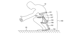
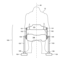
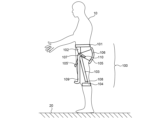
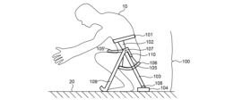
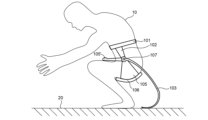
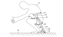
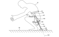
図1は、立っている構成における一実施形態のウェアラブルな下半身支持システム100の側面図の実例を描いている。図2は、しゃがんだ構成における図1に描かれているウェアラブルな下半身支持システムの側面図の実例を描いている。図3は、しゃがんだ構成における図2に描かれているウェアラブルな下半身支持システムの背面図の実例を描いている。
Figure 1 illustrates an example of a side view of an embodiment of a wearable lower
図1~3において描かれているように、ウェアラブルな下半身支持システム100は、腰又はその上で人間のユーザ10の下部胴体の周囲に巻き付けられるハーネス101(例えば、パッドベルト又はベルトのアレイ等)と、ハーネス101に固定して取り付けられた支持プレート要素102とを含む取り外し可能なハーネスアセンブリを含む。ハーネス101は、任意の適した取り付け機構(例えば、バックルファスナー、面ファスナー等)を使用して、人間のユーザ110の下部胴体に取り外し可能に取り付けられる。支持プレート要素102は、人間のユーザ10の両側、例えば矢状面の両側に配置される。加えて、ウェアラブルな下半身支持システム100は、尻部支持構造体106を含む。一部の実施形態において、尻部支持構造体106は、人間のユーザ10の尻部に適合する構造を含み、人間のユーザ10がしゃがみ位にあるときに、人間のユーザ10の尻部を支持する。
1-3, the wearable lower
加えて、ウェアラブルな下半身支持システム100は、人間のユーザ10の両側、例えば矢状面の両側に配置される受動的下半身支持アセンブリを含む。各受動的下半身支持アセンブリは、支持プレート要素102においてハーネスアセンブリに強固に結合された主要な身体支持構造体103を含む。各主要な身体支持構造体103は、作業環境の地面20に向かってハーネスアセンブリから下方に延びる。加えて、各受動的下半身支持アセンブリは、尻部支持構造体106に結合され、且つ回転ジョイント107において支持プレート要素102又は主要な身体支持構造体103に結合された尻部支持フレーム105を含む。尻部支持フレーム105は、回転ジョイント107を中心としてハーネスアセンブリに対して回転する。各尻部支持フレーム105は、回転ジョイント107から離れるように延びるレバーアーム部分105´を含む。一部の実施形態において、レバーアーム部分105´は、例えば、バックルファスナー、面ファスナー等のハーネス(図示せず)によって、人間のユーザ10の大腿上部に取り付けられる。一部の実施形態において、レバーアーム部分105´は、人間のユーザの大腿上部の前に向かって巻きつく。
In addition, the wearable lower
人間のユーザが立位からしゃがみ位まで動くに従い、人間のユーザ10の大腿上部は、レバーアーム部分105´との相互作用によって、回転ジョイント107を中心として尻部支持フレーム105を回転させる。例えば、人間のユーザ10が立位からしゃがみ位まで動くに従い、尻部支持フレーム105は、図2において見られるように時計回りの方向に回転ジョイント107を中心として回転する。回転ジョイント107を中心とした尻部支持フレーム105の回転は、人間のユーザ10の尻部の後ろの位置から人間のユーザ10の尻部の下の位置まで尻部支持構造体106を回転させる。この様式で、尻部支持構造体106は、人間のユーザ10がしゃがみ位をとる場合に人間のユーザ10の体重を支持するように位置する。図1~3において例示されているように、尻部支持構造体106によって支持される体重は、各尻部支持フレーム105を介して、及び回転ジョイント107を通して各主要な身体支持構造体103を介して地面20まで伝えられる。
As the human user moves from a standing position to a crouching position, the upper thighs of the
逆に、人間のユーザがしゃがみ位から立位まで動くに従い、人間のユーザ10の大腿上部が、レバーアーム部分105´との相互作用によって、回転ジョイント107を中心として尻部支持フレーム105を回転させる。例えば、人間のユーザ10がしゃがみ位から立位まで動くに従い、尻部支持フレーム105は、図2において見られるように反時計回りの方向に回転ジョイント107を中心として回転する。回転ジョイント107を中心とした尻部支持フレーム105の回転は、人間のユーザ10の尻部の下の位置から人間のユーザ10の尻部の後ろの位置まで尻部支持構造体106を回転させる。この様式で、尻部支持構造体106は、人間のユーザ10の邪魔にならないように位置し、人間のユーザ10の脚の前後に配置された支持構造体によって妨げられることなく、人間のユーザ10は作業環境の周りを歩くことができる。さらに、立ったり歩いたりするときに、人間のユーザ10の大腿の側面に主要な身体支持構造体を配置することによって、主要な身体支持構造体は、人間のユーザ10の移動運動を妨害せず、周囲の物との衝突を最小限に抑える。
Conversely, as the human user moves from a crouching position to a standing position, the upper thighs of the
立っているときの邪魔にならない位置からしゃがんでいるときの支持位置までのウェアラブルな下半身支持システム100の構成の変更を、人間のユーザ10の大腿上部から自然に駆動することによって、人間のユーザ10は、姿勢が変更するに従いウェアラブルな下半身支持システムに対して明確な手動の調整を行う必要なく、手元のタスクに集中することができる。
By naturally driving the change in configuration of the wearable lower
一般に、尻部支持構造体106、ハーネス101、又はその両方は、矢状面30に直交する方向において比較的剛性である。言い換えると、尻部支持構造体106、ハーネス101、又はその両方は、矢状面30に直交する方向において荷重を受けたときにほとんど変形しない。この様式で、支持プレート要素102への取り付け点における受動的下半身支持アセンブリは、人間のユーザ10の身体に対して比較的安定した位置に配置される。図3において例示されている実施形態では、支持プレート102は、矢状面に直交する方向において比較的小さな寸法を有する(すなわち、薄い)。この様式で、支持プレート要素102は、矢状面30に平行な方向において高い剛性を維持しながら、人間のユーザ10の身体の形状に適合することができる。
In general, the
図1及び2に描かれている実例において見られるように、主要な身体支持構造体103は、人間のユーザ10の脊椎にほぼ平行な方向に延びている。主要な身体支持構造体103は、人間のユーザ10の脊椎の下に延び、人間のユーザ10の尻部が地面20に接触することなく、地面20に接触する。この様式で、主要な身体支持構造体103は、人間のユーザ10の尻部が地面20の上方にあるしゃがみ位の人間のユーザ10の体重を支持する。
As seen in the illustrated example of Figures 1 and 2, the primary
図1~3に描かれている実施形態では、下半身支持システム100の各受動的下半身支持アセンブリは、作業環境の地面に最も近い主要な身体支持構造体103の端部において主要な身体支持構造体103に結合されたエンドエフェクタ構造体104を含む。この様式で、エンドエフェクタ構造体104は、人間のユーザ10の体重を支持するために地面20に接触する。
In the embodiment depicted in Figures 1-3, each passive lower body support assembly of the lower
一部の実施形態において、エンドエフェクタ構造体104は、図2において描かれているように、人間のユーザの体重によって荷重がかかったときに地面の形状に適合する弾性材料から構築された細長いプレート構造体を含む。
In some embodiments, the
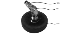
一部の実施形態において、エンドエフェクタ構造体104は、天然ゴム又は合成ゴム等のポリマー材料から構築された円盤形状の構造体を含む。
In some embodiments, the
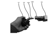
一部の実施形態において、エンドエフェクタ構造体104は、クイックチェンジカプラ機構を用いて、主要な身体支持構造体103に取り外し可能に結合される。
In some embodiments, the
一部の実施形態において、エンドエフェクタ構造体104は、主要な身体支持構造体とエンドエフェクタとの間で結合されるスイベル機構を含む。スイベル機構は、エンドエフェクタに、1つ以上の回転軸を中心として主要な身体支持構造体に対して回転するよう強制して、エンドエフェクタが、最大の接触領域にわたって地面20に接触することを確実にする。加えて、主要な身体支持構造体とエンドエフェクタとの間で結合されたスイベル機構は、ユーザが、しゃがみ位で支持されながら、左右及び前後にピッチするのを可能にする。
In some embodiments, the
図4は、天然ゴムから構築された円盤形状のエンドエフェクタ121を含むエンドエフェクタ構造体の実例を描いている。エンドエフェクタ121は、スイベル機構122に結合され、スイベル機構122は、次に、クイックチェンジカプラの一部分123Aに結合されている。
Figure 4 illustrates an example end effector structure that includes a disk-shaped
図5は、図4において描かれているエンドエフェクタ構造体が、クイックチェンジカプラ123を使用して主要な身体支持構造体103に取り付けられているところの実例を描いている。図5において描かれているように、スイベル122に取り付けられたクイックチェンジカプラの一部分123Aは、主要な身体支持構造体103に取り付けられたクイックチェンジカプラの一部分123Bにマッチする。エンドエフェクタは、クイックチェンジカプラを使用してツールなしで人間のユーザによって主要な身体支持構造体に取り外し可能に結合される。
Figure 5 illustrates an example of the end effector structure depicted in Figure 4 being attached to the main
さらなる態様では、各受動的下半身支持アセンブリは、しゃがみ位の人間のユーザの支持を強化するために、補助の身体支持構造体を含む。 In a further aspect, each passive lower body support assembly includes an auxiliary body support structure to enhance support of a human user in a crouching position.
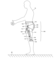
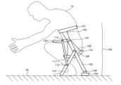
図6は、立っている構成における一実施形態の補助の身体支持構造体を含むウェアラブルな下半身支持システム100の側面図の実例を描いている。図7は、しゃがんだ構成における図6に描かれているウェアラブルな下半身支持システムの側面図の実例を描いている。図8は、補助の身体支持構造体及び主要な身体支持構造体によって地面に接触する点間の距離が最大である、しゃがんだ構成における図6に描かれているウェアラブルな下半身支持システムの側面図の実例を描いている。
Figure 6 illustrates an example of a side view of a wearable lower
図6~8において描かれているように、ウェアラブルな身体支持システム100の各受動的下半身支持アセンブリは、作業環境の地面20に向かってハーネスアセンブリから下方に延びる補助の身体支持構造体109を含む。補助の身体支持構造体109は、回転ジョイント107においてハーネスアセンブリの支持プレート要素102に結合されている。この様式で、補助の身体支持構造体109は、回転ジョイント107を中心としてハーネスアセンブリに対して回転する。一部の他の実施形態では、補助の身体支持構造体109は、回転ジョイント107とは異なる位置で、別の回転ジョイントにおいてハーネスアセンブリの支持プレート要素102に結合される。一部の他の実施形態では、補助の身体支持構造体109は、補助の身体支持構造体109と主要な身体支持構造体103との間の回転ジョイントにおいて主要な身体支持構造体103に結合される。
As depicted in Figures 6-8, each passive lower body support assembly of the wearable
人間のユーザが立位からしゃがみ位まで動くに従い、人間のユーザ10の大腿上部は、レバーアーム部分105´との相互作用によって、回転ジョイント107を中心として尻部支持フレーム105を回転させる。例えば、尻部支持フレーム105は、人間のユーザ10が立位からしゃがみ位まで動くに従い、図7において見られるように時計回りの方向に回転ジョイント107を中心として回転する。回転ジョイント107を中心とした尻部支持フレーム105の回転は、人間のユーザ10の尻部の後ろの位置から人間のユーザ10の尻部の下の位置まで尻部支持構造体106を回転させる。加えて、補助の支持構造体109は、下へ落ち、地面20に接触する。
As the human user moves from a standing position to a crouching position, the upper thighs of the
図8において描かれているように、補助の支持構造体109は、補助の支持構造体109のメカニカルストップ110が主要な身体支持構造体103に接触するまで、地面20に沿って摺動する。この構成において、人間のユーザ10がしゃがみ位をとる場合に、人間のユーザ10は、地面に接触する4点において安定して支持される。図6~8において例示されているように、尻部支持構造体106によって支持される体重は、各尻部支持フレーム105を介して、並びに回転ジョイント107を通して各主要な身体支持構造体103及び補助の身体支持構造体109を介して地面20に伝えられる。
As depicted in FIG. 8, the
別のさらなる態様において、各補助の身体支持構造体は、人間のユーザ10の尻部の後ろの位置から人間のユーザ10の尻部の下の位置まで回転する尻部支持構造体106の回転と協調して展開される。
In another further aspect, each auxiliary body support structure is deployed in coordination with the rotation of the
図9は、立っている構成における別の実施形態の補助の身体支持構造体を含むウェアラブルな下半身支持システム100の側面図の実例を描いている。図10は、しゃがんだ構成における図9に描かれているウェアラブルな下半身支持システムの側面図の実例を描いている。
Figure 9 illustrates an example of a side view of a wearable lower
図9~10において描かれているように、ウェアラブル身体支持システム100の各受動的下半身支持アセンブリは、作業環境の地面20に向かってハーネスアセンブリから下方に延びる補助の身体支持構造体115を含む。補助の身体支持構造体115は、回転ジョイント114において主要な身体支持構造体103に結合されている。この様式で、補助の身体支持構造体115は、回転ジョイント114を中心として主要な身体支持構造体103に対して回転する。加えて、補助の展開リンク111が、回転ジョイント115において身体支持構造体115に、及び、回転ジョイント113において尻部支持フレーム105に結合されている。この構成において、尻部支持フレーム105、主要な身体支持構造体103、補助の身体支持構造体115、及び補助の展開リンク111は、4バーリンケージ機構を形成している。
As depicted in Figures 9-10, each passive lower body support assembly of the wearable
人間のユーザが立位からしゃがみ位まで動くに従い、人間のユーザ10の大腿上部は、レバーアーム部分105´との相互作用によって、回転ジョイント107を中心として尻部支持フレーム105を回転させる。例えば、尻部支持フレーム105は、人間のユーザ10が立位からしゃがみ位まで動くに従い、図9において見られるように時計回りの方向に回転ジョイント107を中心として回転する。回転ジョイント107を中心とした尻部支持フレーム105の回転は、人間のユーザ10の尻部の後ろの位置から人間のユーザ10の尻部の下の位置まで尻部支持構造体106を回転させる。加えて、回転ジョイント107を中心とした尻部支持フレーム105の回転は、図10において描かれているように、補助の支持構造体115が地面20に向かって動くに従い、4バーリンケージに構成を変更させ、補助の支持構造体115を展開させる(すなわち、補助の身体支持構造体115と主要な身体支持構造体103との間の角度を増加させる)。
As the human user moves from a standing position to a crouching position, the upper thighs of the
逆に、人間のユーザ10がしゃがみ位から立位まで動くに従い、人間のユーザ10の大腿上部は、レバーアーム部分105´との相互作用によって、回転ジョイント107を中心として尻部支持フレーム105を回転させる。例えば、人間のユーザ10がしゃがみ位から立位まで動くに従い、尻部支持フレーム105は、図10において見られるように反時計回りの方向に回転ジョイント107を中心として回転する。回転ジョイント107を中心とした尻部支持フレーム105の回転は、人間のユーザ10の尻部の下の位置から人間のユーザ10の尻部の後ろの位置まで尻部支持構造体106を回転させる。加えて、回転ジョイント107を中心とした尻部支持フレーム105の回転は、図9において描かれているように、補助の支持構造体115が地面20から離れるように動くに従い、4バーリンケージに構成を変更させ、補助の支持構造体115を後退させる(すなわち、補助の身体支持構造体115と主要な身体支持構造体103との間の角度を減少させる)。
Conversely, as the
立っているときの邪魔にならない位置からしゃがんでいるときの支持位置までの補助の支持構造体の構成の変更を、人間のユーザ10の大腿上部から自然に駆動することによって、人間のユーザ10は、姿勢が変更するに従い補助の支持構造体に対して明確な手動の調整を行う必要なく、手元のタスクに集中することができる。
By naturally driving the change in configuration of the auxiliary support structure from an out-of-the-way position when standing to a support position when squatting from the upper thighs of the
別の態様では、各主要な身体支持構造体は、人間のユーザの体重によって荷重がかかったときに地面の形状に適合する弾性材料から構築される。 In another aspect, each primary body support structure is constructed from a resilient material that conforms to the shape of the ground when loaded by the weight of a human user.
図11は、人間のユーザの体重によって荷重がかかったときに地面の形状に適合する弾性材料から構築された主要な身体支持構造体を含むウェアラブルな下半身支持システム100の側面図の実例を描いている。
Figure 11 illustrates an example side view of a wearable lower
図11において描かれているように主要な身体支持構造体103は、人間のユーザがしゃがみ姿勢をとり且つ主要な身体支持構造体103に効果的に荷重をかけるに従い、地面20に接触し曲がる。主要な身体支持構造体103は、主要な身体支持構造体の一部が、人間のユーザの体重によって荷重がかかったときに地面の形状に適合し、且つ主要な身体支持構造体と地面20との間に大きな接触領域を効果的に形成するように、十分に柔軟である。例証的な弾性材料は、ポリマーベースの材料、金属等を含み、これらは、曲げ応力下で変形して、主要な身体支持構造体と地面20との間に大きな接触領域を形成する薄い幾何学的形状に形成される。
As depicted in FIG. 11, the primary
別の態様では、各受動的下半身支持アセンブリは、作業環境の地面に最も近い主要な身体支持構造体の端部又はその近くで主要な身体支持構造体に結合された補助の身体支持構造体を含み、しゃがみ位の人間のユーザの支持を強化している。 In another aspect, each passive lower body support assembly includes an auxiliary body support structure coupled to the primary body support structure at or near the end of the primary body support structure closest to the ground in the work environment to provide additional support for a human user in a crouching position.
図12は、作業環境の地面に最も近い主要な身体支持構造体の端部又はその近くで主要な身体支持構造体に結合された補助の身体支持構造体を含むウェアラブルな下半身支持システム100の側面図の実例を描いている。
Figure 12 illustrates an example side view of a wearable lower
補助の身体支持構造体118は、作業環境の地面20に最も近い主要な身体支持構造体103の端部又はその近くに配置された回転ジョイント117において主要な身体支持構造体103に結合されている。加えて、回転ジョイント117を中心とした補助の身体支持構造体117の回転によって復元力が発生するように、ねじりばね116が、主要な身体支持構造体103及び補助の身体支持構造体117に結合されている。
The secondary
図12において描かれているように、人間のユーザがしゃがみ姿勢をとり、且つ主要な身体支持構造体103に効果的に荷重をかけるに従い、補助の身体支持構造体118は、地面20に接触し、主要な身体支持構造体103に対して回転する。補助の身体支持構造体118が、人間のユーザの体重によって荷重がかかったときに地面の形状に適合し、且つ補助の身体支持構造体118と地面20との間に大きな接触領域を効果的に形成するように、補助の身体支持構造体118は十分に柔軟である。例証的な弾性材料は、ポリマーベースの材料、金属等を含み、これらは、曲げ応力下で変形して、補助の身体支持構造体118と地面20との間に大きな接触領域を形成する薄い幾何学的形状に形成される。
As depicted in FIG. 12, as the human user assumes a crouching position and effectively loads the primary
別の態様では、各受動的下半身支持アセンブリは、主要な身体支持構造体に結合され、且つ直線ジョイントに沿って主要な身体支持構造体に対して並進するように強制される補助の身体支持構造体を含み、しゃがみ位の人間のユーザの快適さを向上させている。 In another aspect, each passive lower body support assembly includes an auxiliary body support structure coupled to the primary body support structure and constrained to translate relative to the primary body support structure along a linear joint to improve comfort for a human user in a crouching position.
図13は、主要な身体支持構造体103に結合され、且つ直線ジョイントに沿って主要な身体支持構造体に対して並進するように強制される補助の身体支持構造体120を含むウェアラブルな下半身支持システム100の側面図の実例を描いている。
Figure 13 illustrates an example side view of a wearable lower
補助の身体支持構造体120は、作業環境の地面20に最も近い主要な身体支持構造体103の端部又はその近くに配置された直線(すなわち、並進)ジョイントにおいて主要な身体支持構造体103に結合されている。加えて、直線ジョイント軸130に沿った主要な身体支持構造体103に対する補助の身体支持構造体120の並進移動によって、復元力が発生するように、線形ばね119が、主要な身体支持構造体103及び補助の身体支持構造体120に結合されている。
The secondary
図13において描かれているように、人間のユーザがしゃがみ姿勢をとり、且つ主要な身体支持構造体103に効果的に荷重をかけるに従い、補助の身体支持構造体120は、エンドエフェクタ104を介して地面20に接触し、主要な身体支持構造体103に向かう方向において直線ジョイント軸130に沿って主要な身体支持構造体103に対して並進する。この様式で、主要な身体支持構造体及び補助の身体支持構造体を含む耐荷重性部材は、ウェアラブルな下半身支持システムに荷重をかける及びその荷重を軽減するときに人間のユーザの快適さを増大させる柔軟な部材である。
13, as the human user assumes a crouching position and effectively loads the primary
一般に、本明細書において記載される各身体支持構造体は、ウェアラブルな下半身支持システムに荷重をかける及びその荷重を軽減するときに人間のユーザの快適さを増大させるために、柔軟な二部品構造部材として構成されてもよい。 In general, each body support structure described herein may be configured as a flexible two-piece structural member to increase the comfort of a human user when loading and unloading the wearable lower body support system.
1つ以上の例証的な実施形態において、記載される機能は、ハードウェア、ソフトウェア、ファームウェア、又はそれらの任意の組み合わせで実装されてもよい。ソフトウェアで実装される場合、機能は、1つ以上の命令又はコードとして、コンピュータ読み取り可能媒体上に格納されてもよく又は送信されてもよい。コンピュータ読み取り可能媒体は、ある場所から別の場所へのコンピュータプログラムの転送を容易にする任意の媒体を含む通信媒体とコンピュータ記憶媒体との両方を含む。記憶媒体は、汎用コンピュータ又は専用コンピュータによってアクセス可能な任意の利用可能な媒体であってもよい。例として、限定するものではないが、そのようなコンピュータ読み取り可能媒体は、RAM、ROM、EEPROM、CD-ROM、若しくは他の光ディスク記憶装置、磁気ディスク記憶装置若しくは他の磁気記憶装置、又は、命令若しくはデータ構造の形態で所望のプログラムコード手段を運ぶ又は格納するために使用することができ、且つ、汎用コンピュータ若しくは専用コンピュータ、又は、汎用プロセッサ若しくは専用プロセッサによってアクセス可能な任意の他の媒体を含み得る。また、いずれの接続も、コンピュータ読み取り可能媒体と適宜呼ばれる。例えば、ソフトウェアが、同軸ケーブル、光ファイバケーブル、ツイストペア、デジタル加入者線(DSL)、又は赤外線、無線、及びマイクロ波等の無線技術を使用して、ウェブサイト、サーバ、又は他のリモートソースから送信される場合、同軸ケーブル、光ファイバケーブル、ツイストペア、DSL、又は赤外線、無線、及びマイクロ波等の無線技術は、媒体の定義に含まれる。ディスク(disk/disc)は、本明細書において使用される場合、コンパクトディスク(CD)、レーザディスク、光ディスク、デジタル多用途ディスク(DVD)、フロッピーディスク、及びブルーレイディスクを含み、ディスク(disk)は通常、磁気的にデータを再生し、ディスク(disc)は、レーザを用いて光学的にデータを再生する。上記の組み合わせも、コンピュータ読み取り可能媒体の範囲内に含まれるべきである。 In one or more illustrative embodiments, the functions described may be implemented in hardware, software, firmware, or any combination thereof. If implemented in software, the functions may be stored on or transmitted as one or more instructions or code on a computer-readable medium. Computer-readable media includes both computer storage media and communication media, including any medium that facilitates transfer of a computer program from one place to another. Storage media may be any available medium accessible by a general purpose or special purpose computer. By way of example, and not limitation, such computer-readable media may include RAM, ROM, EEPROM, CD-ROM, or other optical disk storage, magnetic disk storage, or other magnetic storage, or any other medium that can be used to carry or store desired program code means in the form of instructions or data structures and that can be accessed by a general purpose or special purpose computer, or a general purpose or special purpose processor. Any connection may also be referred to as a computer-readable medium, as appropriate. For example, if the software is transmitted from a website, server, or other remote source using coaxial cable, fiber optic cable, twisted pair, digital subscriber line (DSL), or wireless technologies such as infrared, radio, and microwave, the coaxial cable, fiber optic cable, twisted pair, DSL, or wireless technologies such as infrared, radio, and microwave are included in the definition of media. Disk/disc, as used herein, includes compact discs (CDs), laser discs, optical discs, digital versatile discs (DVDs), floppy disks, and Blu-ray discs, where disks typically reproduce data magnetically and discs reproduce data optically using lasers. Combinations of the above should also be included within the scope of computer-readable media.
ある特定の実施形態が教育目的で上述されているけれども、本特許文献の教示は、一般的な適用可能性を有し、上述の特定の実施形態に限定されない。従って、記載された実施形態の様々な特徴の様々な修正、適応、及び組み合わせを、特許請求の範囲に記載された本発明の範囲から逸脱することなく実施することができる。
Although certain specific embodiments are described above for educational purposes, the teachings of this patent document have general applicability and are not limited to the specific embodiments described above. Thus, various modifications, adaptations, and combinations of the various features of the described embodiments can be made without departing from the scope of the invention as set forth in the claims.
Claims (9)
前記ハーネスに取り付けられて前記ユーザの両側に配置される支持プレート要素と、support plate elements attached to the harness and positioned on either side of the user;
前記支持プレート要素に固定され、前記ユーザの立位で作業環境の地面に接することなく下方へ延び、前記ユーザのしゃがみ位で前記地面に接する主要な身体支持構造体と、a main body support structure secured to the support plate element, extending downwardly without contacting the ground of the work environment when the user is in a standing position, and contacting the ground when the user is in a crouching position;
前記支持プレート要素又は前記主要な身体支持構造体に回転ジョイントを中心として回転可能に結合されて前記ユーザの両側に配置される尻部支持フレームと、buttock support frames rotatably coupled to the support plate elements or the main body support structure about a rotation joint and positioned on either side of the user;
各々の前記尻部支持フレームに結合されて前記ユーザの尻部を支持する尻部支持構造体と、を備え、a hip support structure coupled to each of the hip support frames to support the user's hips;
各々の前記尻部支持フレームは、前記回転ジョイントから離れるように延びて前記ユーザの大腿上部に取り付けられるレバーアーム部分を含む、Each of the buttock support frames includes a lever arm portion extending away from the rotation joint and attached to the upper thigh of the user.
下半身支持システム。Lower body support system.
前記補助の身体支持構造は、前記ユーザの立位で前記主要な身体支持構造体よりも前記ユーザの後方側へ延びるメカニカルストップを有し、the secondary body support structure has a mechanical stop that extends further rearwardly of the user than the primary body support structure when the user is in a standing position;
前記メカニカルストップは、前記ユーザのしゃがみ位で前記主要な身体支持構造体に接触して前記回転ジョイントを中心とする前記ユーザの前方側への前記補助の身体支持構造体の回転を規制する、the mechanical stop contacts the main body support structure when the user is in a crouching position to restrict rotation of the secondary body support structure about the rotation joint toward the front of the user;
請求項1に記載の下半身支持システム。The lower body support system of claim 1 .
前記第2の回転ジョイントを中心に回転可能に前記主要な身体支持構造体に結合され、前記ユーザの立位で前記地面に接することなく下方へ延びる補助の身体支持構造体と、an auxiliary body support structure rotatably coupled to the main body support structure about the second revolute joint and extending downwardly without contacting the ground when the user is in a standing position;
前記補助の身体支持構造体に設けられた第3の回転ジョイントと、a third revolute joint provided on the auxiliary body support structure; and
前記レバーアーム部分に設けられた第4の回転ジョイントと、a fourth rotary joint provided in the lever arm portion;
前記第3の回転ジョイントを中心に回転可能に前記補助の身体支持構造体に結合されるとともに、前記第4の回転ジョイントを中心に回転可能に前記レバーアーム部分に結合される展開リンクと、をさらに備え、a deployment link rotatably coupled to the auxiliary body support structure about the third revolute joint and rotatably coupled to the lever arm portion about the fourth revolute joint;
前記展開リンクは、前記ユーザが立位からしゃがみ位まで動くに従い、前記回転ジョイントを中心として回転する前記レバーアーム部分に連動して前記補助の身体支持構造体を前記ユーザの前方側に展開させて前記地面に接触させる、The deployment link is linked to the lever arm portion that rotates about the rotary joint as the user moves from a standing position to a crouching position, to deploy the auxiliary body support structure forward of the user and into contact with the ground.
請求項1に記載の下半身支持システム。The lower body support system of claim 1 .
請求項1に記載の下半身支持システム。The lower body support system of claim 1 .
前記第2の回転ジョイントを中心とした回転に対する復元力が発生するように前記主要な支持構造体に回転可能に結合され、前記ユーザの立位で前記地面に接することなく下方へ延び、前記ユーザのしゃがみ位で前記地面に接触して前記主要な身体支持構造体に対して回転することで前記地面との間に接触領域を形成する補助の身体支持構造体と、をさらに備える、an auxiliary body support structure rotatably coupled to the main support structure so as to generate a restoring force against rotation about the second rotary joint, the auxiliary body support structure extending downwardly without contacting the ground when the user is in a standing position, and contacting the ground and rotating relative to the main body support structure to form a contact area with the ground when the user is in a crouching position;
請求項1に記載の下半身支持システム。The lower body support system of claim 1 .
前記直線ジョイントにおいて前記主要な身体支持構造体に結合され、前記ユーザの立位で前記地面に接することなく下方へ延び、前記ユーザのしゃがみ位で前記地面に接触して前記主要な身体支持構造体に対して並進する補助の身体支持構造体と、an auxiliary body support structure coupled to the main body support structure at the linear joint, extending downwardly without contacting the ground when the user is in a standing position, and contacting the ground and translating relative to the main body support structure when the user is in a crouching position;
前記直線ジョイントに沿った前記主要な身体支持構造体に対する前記補助の身体支持構造体の並進移動によって復元力を発生させる線形ばねと、をさらに備える、a linear spring generating a restoring force upon translation of the secondary body support structure relative to the primary body support structure along the linear joint.
請求項1に記載の下半身支持システム。The lower body support system of claim 1 .
尻部支持構造体と、
第1の受動的下半身支持アセンブリ及び第2の受動的下半身支持アセンブリと、
を含む下半身支持システムであって、
前記第1の受動的下半身支持アセンブリ及び前記第2の受動的下半身支持アセンブリは各々、
前記ハーネスアセンブリに強固に結合された主要な身体支持構造体であり、作業環境の地面に向かって前記ハーネスアセンブリから下方に延びる主要な身体支持構造体、及び
前記尻部支持構造体に強固に結合され、且つ回転ジョイントにおいて前記ハーネスアセンブリ又は前記主要な身体支持構造体に結合された尻部支持フレームであり、前記回転ジョイントを中心として前記ハーネスアセンブリに対して回転可能な尻部支持フレーム、
を含み、
前記第1の受動的下半身支持アセンブリは、人間のユーザの胴体の第1の側で前記ハーネスアセンブリ及び前記尻部支持構造体に結合され、前記第2の受動的下半身支持アセンブリは、前記第1の側とは反対の人間のユーザの胴体の第2の側で前記ハーネスアセンブリ及び前記尻部支持構造体に結合されており、
前記第1の受動的下半身支持アセンブリ及び前記第2の受動的下半身支持アセンブリは各々、
前記主要な身体支持構造体に結合され、直線ジョイントに沿って前記主要な身体支持構造体に対して並進するように強制される補助の身体支持構造体、及び
前記主要な身体支持構造体及び前記補助の身体支持構造体に結合されたばねであって、前記主要な身体支持構造体と前記補助の身体支持構造体との間の力が、前記直線ジョイントに沿って前記主要な身体支持構造体に対して前記補助の身体支持構造体を相対的に変位させることによって誘発される、ばね、
をさらに含む、下半身支持システム。 a harness assembly removably attached to a torso of a human user;
A buttocks support structure;
a first passive lower body support assembly and a second passive lower body support assembly;
A lower body support system comprising:
The first passive lower body support assembly and the second passive lower body support assembly each include:
a primary body support structure rigidly coupled to the harness assembly, the primary body support structure extending downwardly from the harness assembly toward a ground surface of the work environment; and a hip support frame rigidly coupled to the hip support structure and coupled to the harness assembly or the primary body support structure at a rotation joint, the hip support frame rotatable relative to the harness assembly about the rotation joint.
Including,
the first passive lower body support assembly is coupled to the harness assembly and the hip support structure on a first side of a human user's torso, and the second passive lower body support assembly is coupled to the harness assembly and the hip support structure on a second side of the human user's torso opposite the first side;
The first passive lower body support assembly and the second passive lower body support assembly each include:
a secondary body support structure coupled to the primary body support structure and constrained to translate relative to the primary body support structure along a linear joint; and
a spring coupled to the primary body support structure and the secondary body support structure, wherein a force between the primary body support structure and the secondary body support structure is induced by displacing the secondary body support structure relative to the primary body support structure along the linear joint;
The lower body support system further includes :
尻部支持構造体と、
第1の受動的下半身支持アセンブリ及び第2の受動的下半身支持アセンブリと、
を含む下半身支持システムであって、
前記第1の受動的下半身支持アセンブリ及び前記第2の受動的下半身支持アセンブリは各々、
前記ハーネスアセンブリに強固に結合された主要な身体支持構造体であり、作業環境の地面に向かって前記ハーネスアセンブリから下方に延びる主要な身体支持構造体、及び
前記尻部支持構造体に強固に結合され、且つ回転ジョイントにおいて前記ハーネスアセンブリ又は前記主要な身体支持構造体に結合された尻部支持フレームであり、前記回転ジョイントを中心として前記ハーネスアセンブリに対して回転可能な尻部支持フレーム、
を含み、
前記第1の受動的下半身支持アセンブリは、人間のユーザの胴体の第1の側で前記ハーネスアセンブリ及び前記尻部支持構造体に結合され、前記第2の受動的下半身支持アセンブリは、前記第1の側とは反対の人間のユーザの胴体の第2の側で前記ハーネスアセンブリ及び前記尻部支持構造体に結合されており、
前記第1の受動的下半身支持アセンブリ及び前記第2の受動的下半身支持アセンブリは各々、
前記作業環境の地面に最も近い前記主要な身体支持構造体の端部において前記主要な身体支持構造体に結合されたエンドエフェクタ構造体をさらに含み、
前記エンドエフェクタ構造体は、前記主要な身体支持構造体に取り外し可能に結合され、エンドエフェクタアセンブリが、前記主要な身体支持構造体に取り外し可能に結合されるクイックチェンジカプラを含み、前記クイックチェンジカプラは、ツールなしで前記人間のユーザによって、前記主要な身体支持構造体に結合され、前記主要な身体支持構造体から分離される、下半身支持システム。 a harness assembly removably attached to a torso of a human user;
A buttocks support structure;
a first passive lower body support assembly and a second passive lower body support assembly;
A lower body support system comprising:
The first passive lower body support assembly and the second passive lower body support assembly each include:
a primary body support structure rigidly coupled to the harness assembly, the primary body support structure extending downwardly from the harness assembly toward a ground surface of the work environment; and
a hip support frame rigidly coupled to the hip support structure and coupled to the harness assembly or the main body support structure at a rotation joint, the hip support frame rotatable relative to the harness assembly about the rotation joint;
Including,
the first passive lower body support assembly is coupled to the harness assembly and the hip support structure on a first side of a human user's torso, and the second passive lower body support assembly is coupled to the harness assembly and the hip support structure on a second side of the human user's torso opposite the first side;
The first passive lower body support assembly and the second passive lower body support assembly each include:
an end effector structure coupled to the main body support structure at an end of the main body support structure closest to a ground surface of the work environment;
A lower body support system, wherein the end effector structure is releasably coupled to the main body support structure, and the end effector assembly includes a quick-change coupler that is releasably coupled to the main body support structure, the quick-change coupler being coupled to and decoupled from the main body support structure by the human user without tools .
尻部支持構造体と、
第1の受動的下半身支持アセンブリ及び第2の受動的下半身支持アセンブリと、
を含む下半身支持システムであって、
前記第1の受動的下半身支持アセンブリ及び前記第2の受動的下半身支持アセンブリは各々、
前記ハーネスアセンブリに強固に結合された主要な身体支持構造体であり、作業環境の地面に向かって前記ハーネスアセンブリから下方に延びる主要な身体支持構造体、及び
前記尻部支持構造体に強固に結合され、且つ回転ジョイントにおいて前記ハーネスアセンブリ又は前記主要な身体支持構造体に結合された尻部支持フレームであり、前記回転ジョイントを中心として前記ハーネスアセンブリに対して回転可能な尻部支持フレーム、
を含み、
前記第1の受動的下半身支持アセンブリは、人間のユーザの胴体の第1の側で前記ハーネスアセンブリ及び前記尻部支持構造体に結合され、前記第2の受動的下半身支持アセンブリは、前記第1の側とは反対の人間のユーザの胴体の第2の側で前記ハーネスアセンブリ及び前記尻部支持構造体に結合されており、
前記第1の受動的下半身支持アセンブリ及び前記第2の受動的下半身支持アセンブリは各々、
第2の回転ジョイントにおいて前記主要な身体支持構造体に結合された補助の身体支持構造体であって、前記作業環境の地面に向かって前記主要な身体支持構造体から下方に延びる補助の身体支持構造体と、
第3の回転ジョイントにおいて前記補助の身体支持構造体、及び第4の回転ジョイントにおいて前記尻部支持フレームに結合されたリンク構造体と、
をさらに含む、下半身支持システム。 a harness assembly removably attached to a torso of a human user;
A buttocks support structure;
a first passive lower body support assembly and a second passive lower body support assembly;
A lower body support system comprising:
The first passive lower body support assembly and the second passive lower body support assembly each include:
a primary body support structure rigidly coupled to the harness assembly, the primary body support structure extending downwardly from the harness assembly toward a ground surface of the work environment; and
a hip support frame rigidly coupled to the hip support structure and coupled to the harness assembly or the main body support structure at a rotation joint, the hip support frame rotatable relative to the harness assembly about the rotation joint;
Including,
the first passive lower body support assembly is coupled to the harness assembly and the hip support structure on a first side of a human user's torso, and the second passive lower body support assembly is coupled to the harness assembly and the hip support structure on a second side of the human user's torso opposite the first side;
The first passive lower body support assembly and the second passive lower body support assembly each include:
an auxiliary body support structure coupled to the main body support structure at a second revolute joint, the auxiliary body support structure extending downwardly from the main body support structure toward a ground surface of the work environment;
a link structure coupled to the auxiliary body support structure at a third revolute joint and to the hip support frame at a fourth revolute joint;
The lower body support system further includes:
Applications Claiming Priority (5)
| Application Number | Priority Date | Filing Date | Title |
|---|---|---|---|
| US201962879247P | 2019-07-26 | 2019-07-26 | |
| US62/879,247 | 2019-07-26 | ||
| PCT/US2020/043617 WO2021021679A1 (en) | 2019-07-26 | 2020-07-24 | Lower body support system to facilitate floor level task execution by humans |
| US16/938,839 | 2020-07-24 | ||
| US16/938,839 US11877670B2 (en) | 2019-07-26 | 2020-07-24 | Lower body support system to facilitate floor level task execution by humans |
Publications (2)
| Publication Number | Publication Date |
|---|---|
| JP2022542169A JP2022542169A (en) | 2022-09-29 |
| JP7581322B2 true JP7581322B2 (en) | 2024-11-12 |
Family
ID=74188019
Family Applications (1)
| Application Number | Title | Priority Date | Filing Date |
|---|---|---|---|
| JP2022505400A Active JP7581322B2 (en) | 2019-07-26 | 2020-07-24 | A lower body support system to facilitate human performance of floor-level tasks |
Country Status (3)
| Country | Link |
|---|---|
| US (1) | US11877670B2 (en) |
| JP (1) | JP7581322B2 (en) |
| WO (1) | WO2021021679A1 (en) |
Families Citing this family (2)
| Publication number | Priority date | Publication date | Assignee | Title |
|---|---|---|---|---|
| JP7853030B2 (en) * | 2021-02-12 | 2026-04-28 | 住友重機械工業株式会社 | Support devices |
| FR3166044A1 (en) * | 2024-09-12 | 2026-03-13 | Grtgaz | Back support |
Citations (5)
| Publication number | Priority date | Publication date | Assignee | Title |
|---|---|---|---|---|
| US20060102423A1 (en) | 2004-07-12 | 2006-05-18 | Lang Tracy H | Safety harnesses |
| JP2007276086A (en) | 2006-04-11 | 2007-10-25 | Yaskawa Electric Corp | Robot and robot control method |
| US20110040216A1 (en) | 2005-03-31 | 2011-02-17 | Massachusetts Institute Of Technology | Exoskeletons for running and walking |
| JP2013208672A (en) | 2012-03-30 | 2013-10-10 | Fujitsu Ltd | Robot hand, robot and detaching method |
| JP2017100196A (en) | 2015-11-30 | 2017-06-08 | セイコーエプソン株式会社 | Robot and control method |
Family Cites Families (31)
| Publication number | Priority date | Publication date | Assignee | Title |
|---|---|---|---|---|
| US406328A (en) * | 1889-07-02 | Peters | ||
| US671638A (en) * | 1900-07-24 | 1901-04-09 | Edwin Slagle | Stool and cane. |
| US690122A (en) * | 1901-07-18 | 1901-12-31 | Edwin Slagle | Combined stool and cane. |
| US1220316A (en) * | 1916-06-27 | 1917-03-27 | Edward Bragg | Milking-stool. |
| US1417250A (en) * | 1920-04-14 | 1922-05-23 | Kelly Robert Emmett | Back brace |
| US1709200A (en) * | 1928-01-17 | 1929-04-16 | Westbrook | Sanitary milking rest |
| US2099345A (en) * | 1937-01-06 | 1937-11-16 | Peter A Olszanowski | Body support or stool |
| US4095842A (en) * | 1977-04-27 | 1978-06-20 | Tredhill Manufacturing Co. Inc. | Seat for gardening and the like |
| US4138156A (en) * | 1977-09-06 | 1979-02-06 | Bonner Darcy R | Wearable chair |
| JP2002125789A (en) | 2000-10-20 | 2002-05-08 | Haruo Miyamoto | Chair to be attached to body |
| US9616274B2 (en) * | 2005-03-01 | 2017-04-11 | Michael A. Wehrell | Swing training apparatus and method |
| US9561149B2 (en) * | 2008-01-07 | 2017-02-07 | Lite Run, Inc. | Suspension and body attachment system and differential pressure suit for body weight support devices |
| US7980625B2 (en) * | 2008-06-13 | 2011-07-19 | Christian Shane Worthington | Back jack |
| US20160135604A1 (en) * | 2013-07-04 | 2016-05-19 | Ofrees Co., Ltd. | Wearable chair apparatus |
| KR102146363B1 (en) * | 2013-10-31 | 2020-08-20 | 삼성전자주식회사 | Wearable robot and control method for the same |
| WO2015107577A1 (en) * | 2014-01-15 | 2015-07-23 | パナソニック株式会社 | Lower extremity support tool |
| US20160331486A1 (en) * | 2014-01-15 | 2016-11-17 | Panasonic Corporation | Working posture holding device |
| JP2016034461A (en) | 2014-08-01 | 2016-03-17 | 田中 佐知子 | Portable folding chair |
| EP3158893B1 (en) * | 2015-10-21 | 2021-04-28 | noonee AG | Seat unit for wearable sitting posture assisting device |
| US10213356B2 (en) * | 2015-12-10 | 2019-02-26 | Cadence Biomedical | Orthosis device |
| EP3241531A1 (en) * | 2016-05-04 | 2017-11-08 | noonee AG | Leg unit for a wearable sitting posture assisting device |
| JP6742196B2 (en) * | 2016-08-24 | 2020-08-19 | Cyberdyne株式会社 | Life activity detection device and life activity detection system |
| ES2808778T3 (en) * | 2016-11-08 | 2021-03-01 | Noonee Ag | Wearable sitting posture assist device |
| DE102018103300A1 (en) * | 2018-02-14 | 2019-08-14 | Noonee Ag | Portable sitting position help device |
| KR102588952B1 (en) * | 2018-11-02 | 2023-10-16 | 현대자동차주식회사 | Wearable chair with truss structure |
| KR102603039B1 (en) * | 2018-11-20 | 2023-11-16 | 현대자동차주식회사 | Wearable chair with four-link structure |
| KR102762504B1 (en) * | 2018-12-27 | 2025-02-06 | 삼성전자주식회사 | wearable chair |
| KR102681454B1 (en) * | 2019-04-02 | 2024-07-04 | 현대자동차주식회사 | Seating support device of wearable chair |
| JP7389982B2 (en) | 2019-05-28 | 2023-12-01 | 地方独立行政法人北海道立総合研究機構 | weight support device |
| US11826298B2 (en) * | 2019-10-16 | 2023-11-28 | Springactive, Inc. | Preloaded personal augmentation suit and method for assisted human motion |
| US11135123B2 (en) * | 2020-01-26 | 2021-10-05 | Dorian Hunter Alberti | Exoskeletal body support system |
-
2020
- 2020-07-24 JP JP2022505400A patent/JP7581322B2/en active Active
- 2020-07-24 WO PCT/US2020/043617 patent/WO2021021679A1/en not_active Ceased
- 2020-07-24 US US16/938,839 patent/US11877670B2/en active Active
Patent Citations (5)
| Publication number | Priority date | Publication date | Assignee | Title |
|---|---|---|---|---|
| US20060102423A1 (en) | 2004-07-12 | 2006-05-18 | Lang Tracy H | Safety harnesses |
| US20110040216A1 (en) | 2005-03-31 | 2011-02-17 | Massachusetts Institute Of Technology | Exoskeletons for running and walking |
| JP2007276086A (en) | 2006-04-11 | 2007-10-25 | Yaskawa Electric Corp | Robot and robot control method |
| JP2013208672A (en) | 2012-03-30 | 2013-10-10 | Fujitsu Ltd | Robot hand, robot and detaching method |
| JP2017100196A (en) | 2015-11-30 | 2017-06-08 | セイコーエプソン株式会社 | Robot and control method |
Also Published As
| Publication number | Publication date |
|---|---|
| WO2021021679A1 (en) | 2021-02-04 |
| US20210022513A1 (en) | 2021-01-28 |
| US11877670B2 (en) | 2024-01-23 |
| JP2022542169A (en) | 2022-09-29 |
Similar Documents
| Publication | Publication Date | Title |
|---|---|---|
| JP6483081B2 (en) | Non-human hip position for exoskeleton | |
| JP7581322B2 (en) | A lower body support system to facilitate human performance of floor-level tasks | |
| US9827162B1 (en) | Mobile body unweighted sit and stand chair assembly and method of operation | |
| WO2016021103A1 (en) | Movement assistance device | |
| US11613001B2 (en) | Leg augmentation systems and methods for use | |
| JPWO2018168112A1 (en) | Assistance device | |
| EP2055288B1 (en) | Walking assistance device | |
| WO2019198269A1 (en) | Walking assist device | |
| WO2001039633A1 (en) | Chair | |
| KR20090091206A (en) | Anterior support | |
| KR101690422B1 (en) | Assistant apparatus for sitting works | |
| CN112076058A (en) | Chair type massage machine and massage machine | |
| JP6550023B2 (en) | Attitude holding device | |
| JP2023552557A (en) | Hip exoskeleton structure for lifting and pressing | |
| US20200306120A1 (en) | Tilting mobility scooter device | |
| JP5987598B2 (en) | Body holder and transfer support device | |
| KR102493959B1 (en) | Assistive devices that support the muculoskeletal system | |
| JP7366596B2 (en) | Massage machine | |
| KR102493960B1 (en) | Wearing device with adjustable angle | |
| Verjans et al. | Modelling patient dynamics and controller impact analysis for a novel self-stabilizing patient transport aid | |
| KR20220143101A (en) | market device | |
| US20260053685A1 (en) | Assistance device equipped with handle and movement device using same | |
| KR20250033612A (en) | Dog wheelchair | |
| KR101454972B1 (en) | Chair putting on the human body | |
| JP6616483B1 (en) | Assist device |
Legal Events
| Date | Code | Title | Description |
|---|---|---|---|
| A711 | Notification of change in applicant |
Free format text: JAPANESE INTERMEDIATE CODE: A711 Effective date: 20230612 |
|
| A521 | Request for written amendment filed |
Free format text: JAPANESE INTERMEDIATE CODE: A821 Effective date: 20230612 |
|
| A621 | Written request for application examination |
Free format text: JAPANESE INTERMEDIATE CODE: A621 Effective date: 20230714 |
|
| A131 | Notification of reasons for refusal |
Free format text: JAPANESE INTERMEDIATE CODE: A131 Effective date: 20240521 |
|
| A521 | Request for written amendment filed |
Free format text: JAPANESE INTERMEDIATE CODE: A523 Effective date: 20240718 |
|
| TRDD | Decision of grant or rejection written | ||
| A01 | Written decision to grant a patent or to grant a registration (utility model) |
Free format text: JAPANESE INTERMEDIATE CODE: A01 Effective date: 20241001 |
|
| A61 | First payment of annual fees (during grant procedure) |
Free format text: JAPANESE INTERMEDIATE CODE: A61 Effective date: 20241030 |
|
| R150 | Certificate of patent or registration of utility model |
Ref document number: 7581322 Country of ref document: JP Free format text: JAPANESE INTERMEDIATE CODE: R150 |