KR20220143101A - market device - Google Patents
market device Download PDFInfo
- Publication number
- KR20220143101A KR20220143101A KR1020227032230A KR20227032230A KR20220143101A KR 20220143101 A KR20220143101 A KR 20220143101A KR 1020227032230 A KR1020227032230 A KR 1020227032230A KR 20227032230 A KR20227032230 A KR 20227032230A KR 20220143101 A KR20220143101 A KR 20220143101A
- Authority
- KR
- South Korea
- Prior art keywords
- armpit support
- armpit
- pair
- support
- person
- Prior art date
Links
Images


Classifications
-
- A—HUMAN NECESSITIES
- A61—MEDICAL OR VETERINARY SCIENCE; HYGIENE
- A61G—TRANSPORT, PERSONAL CONVEYANCES, OR ACCOMMODATION SPECIALLY ADAPTED FOR PATIENTS OR DISABLED PERSONS; OPERATING TABLES OR CHAIRS; CHAIRS FOR DENTISTRY; FUNERAL DEVICES
- A61G7/00—Beds specially adapted for nursing; Devices for lifting patients or disabled persons
- A61G7/10—Devices for lifting patients or disabled persons, e.g. special adaptations of hoists thereto
-
- A—HUMAN NECESSITIES
- A61—MEDICAL OR VETERINARY SCIENCE; HYGIENE
- A61G—TRANSPORT, PERSONAL CONVEYANCES, OR ACCOMMODATION SPECIALLY ADAPTED FOR PATIENTS OR DISABLED PERSONS; OPERATING TABLES OR CHAIRS; CHAIRS FOR DENTISTRY; FUNERAL DEVICES
- A61G5/00—Chairs or personal conveyances specially adapted for patients or disabled persons, e.g. wheelchairs
- A61G5/10—Parts, details or accessories
- A61G5/14—Standing-up or sitting-down aids
-
- A—HUMAN NECESSITIES
- A61—MEDICAL OR VETERINARY SCIENCE; HYGIENE
- A61G—TRANSPORT, PERSONAL CONVEYANCES, OR ACCOMMODATION SPECIALLY ADAPTED FOR PATIENTS OR DISABLED PERSONS; OPERATING TABLES OR CHAIRS; CHAIRS FOR DENTISTRY; FUNERAL DEVICES
- A61G7/00—Beds specially adapted for nursing; Devices for lifting patients or disabled persons
- A61G7/10—Devices for lifting patients or disabled persons, e.g. special adaptations of hoists thereto
- A61G7/104—Devices carried or supported by
- A61G7/1046—Mobile bases, e.g. having wheels
-
- A—HUMAN NECESSITIES
- A61—MEDICAL OR VETERINARY SCIENCE; HYGIENE
- A61G—TRANSPORT, PERSONAL CONVEYANCES, OR ACCOMMODATION SPECIALLY ADAPTED FOR PATIENTS OR DISABLED PERSONS; OPERATING TABLES OR CHAIRS; CHAIRS FOR DENTISTRY; FUNERAL DEVICES
- A61G7/00—Beds specially adapted for nursing; Devices for lifting patients or disabled persons
- A61G7/10—Devices for lifting patients or disabled persons, e.g. special adaptations of hoists thereto
- A61G7/1049—Attachment, suspending or supporting means for patients
Abstract
기대와, 피시중자의 좌우의 겨드랑이를 각각 지지하는 한 벌의 겨드랑이 지지부와, 상기 기대를 기준으로 하여 한 벌의 상기 겨드랑이 지지부를 적어도 상하 방향으로 이동시키는 구동부를 구비하는 시중 장치로서, 상기 겨드랑이 지지부는, 상기 피시중자의 적어도 상기 겨드랑이 및 상완부에 접촉하는 통상 표면부와, 상기 통상 표면부보다도 작은 마찰 계수를 가지고 상기 피시중자의 옆구리부에 접촉하는 마찰 저감 표면부를 가진다.A commercial device comprising: a base; a pair of axillary support for supporting the left and right armpits of the target person, respectively; has a normal surface portion in contact with at least the armpit and upper arm of the center of gravity, and a friction reducing surface portion in contact with the side of the center of gravity having a friction coefficient smaller than that of the normal surface portion.
Description
본 명세서는 피시중자의 겨드랑이를 지지하는 겨드랑이 지지부를 구비한 시중 장치에 관한 것이다.The present specification relates to a commercial device having an armpit support for supporting the armpit of a fisherman.
고령화 사회의 진전에 수반하여, 시중 장치의 요구가 증대하고 있다. 시중 장치는, 일반적으로, 피시중자의 신체의 일부를 지지한 지지 부재를 구동하여, 피시중자의 각종의 동작을 시중든다. 피시중자의 기립 동작이나 착좌(着座) 동작을 시중드는 시중 장치는, 피시중자의 좌우의 겨드랑이를 각각 지지하는 한 벌의 겨드랑이 지지부나, 피시중자의 상체를 지지하는 상체 지지부를 구비한 것이 많다. 시중 장치의 도입에 의해, 시중자 및 피시중자의 신체적인 부담이 경감됨과 아울러, 시중자의 일손 부족도 완화된다. 이런 종류의 시중 장치의 한 기술예가 특허 문헌 1에 개시되어 있다.With the progress of an aging society, demands for commercial devices are increasing. In general, the assisting device drives a support member that supports a part of the person's body to attend various operations of the person. Many assistive devices that assist the person's standing and sitting motions are provided with a pair of armpit supports that support the left and right armpits of the person, respectively, or an upper body support that supports the upper body of the person. The introduction of the assistive device reduces the physical burden of the attendant and the attendee, and also alleviates the labor shortage of the attendant. One technical example of this kind of commercial device is disclosed in
특허 문헌 1의 시중 장치는, 기대(基臺)와, 피시중자의 좌우의 겨드랑이를 지지하면서 기대에 대한 상대적인 이동이 가능한 겨드랑이 지지부와, 겨드랑이 지지부를 구동하는 구동부를 구비한다. 그리고, 겨드랑이 지지부는, 심(芯) 부재와, 심 부재에 대해 회전 가능하게 설치되고 피시중자의 동체에 접촉하는 외주(外周) 부재를 가진다. 이에 의하면, 외주 부재는, 피시중자의 자세 변화에 추종하면서 심 부재에 대해 회전할 수가 있다. 따라서, 피시중자와 겨드랑이 지지부의 사이에 발생하는 마찰력은, 완화되어 억제되고, 피시중자의 쾌적한 사용감이 실현된다.The commercial apparatus of
그런데, 특허 문헌 1의 시중 장치는, 심 부재에 대해 외주 부재가 회전함으로써, 피시중자의 옆구리부에 마찰력으로 생기는 아픔을 경감시킬 수 있는 점에서 바람직하다. 그렇지만, 외주 부재가 무한하게 회전하는 구성이라면, 겨드랑이 지지부가 피시중자를 안아 올리는 힘이 사라져 버려, 본래의 역할을 다할 수 없게 된다. 이 때문에, 외주 부재의 회전량은 제한되어 있고, 그 결과, 마찰력에 의해 생기는 아픔의 경감에는 한계가 있었다. 또, 겨드랑이 지지부는 피시중자의 체중의 반 이상에 상당하는 하중을 지지하는 경우가 있다. 이 경우, 피시중자는 겨드랑이 지지부가 양쪽 겨드랑이를 밀어 올리는 강한 압박감에 의해 아픔을 느끼는 일이 있었다.By the way, the market apparatus of
또한, 일부의 시중 장치에서는, 한 벌의 겨드랑이 지지부에 작용하는 하향의 하중에 응하여, 한 벌의 겨드랑이 지지부를 서로 접근하는 방향으로 요동 또는 이동시켜, 피시중자를 확실하게 지지할 수 있도록 한 구성도 채용되고 있다. 이 구성에 있어서, 피시중자는, 좌우의 겨드랑이 지지부가 옆구리부를 끼워 넣는 압박력에 의해 아픔을 느끼는 일이 있었다. 이 아픔은 몸집이 큰 체격의 피시중자에게 현저하게 되기 쉽다.In addition, in some commercial devices, in response to the downward load acting on the pair of armpit supports, the pair of armpit supports swings or moves in a direction approaching each other, so that the structure diagram can reliably support the fisherman. are being hired In this configuration, the recipient may feel pain due to the pressing force between the left and right armpit support portions sandwiching the flanks. This pain is likely to become conspicuous for a person with a large physique.
그러므로, 본 명세서에서는, 피시중자의 아픔을 경감하여 쾌적한 사용감을 실현한 시중 장치를 제공하는 것을 해결해야 할 과제로 한다.Therefore, in the present specification, it is a problem to be solved to provide a commercial device that reduces the pain of a person and realizes a comfortable feeling of use.
본 명세서는, 기대와, 피시중자의 좌우의 겨드랑이를 각각 지지하는 한 벌의 겨드랑이 지지부와, 상기 기대를 기준으로 하여 한 벌의 상기 겨드랑이 지지부를 적어도 상하 방향으로 이동시키는 구동부를 구비하는 시중 장치로서, 상기 겨드랑이 지지부는, 상기 피시중자의 적어도 상기 겨드랑이 및 상완(上腕)부에 접촉하는 통상(通常) 표면부와, 상기 통상 표면부보다도 작은 마찰 계수를 가지고 상기 피시중자의 옆구리부에 접촉하는 마찰 저감 표면부를 가지는 시중 장치를 개시한다.The present specification is a commercial device having a base, a pair of axillary support parts for supporting the left and right armpits of the target person, respectively; , The armpit support part has a friction coefficient smaller than that of the normal surface part and the normal surface part contacting at least the said armpit and the upper arm part of the said fish center, and the friction which contacts the side part of the said fish center part. A commercial device having a reduced surface portion is disclosed.
이에 의하면, 겨드랑이 지지부의 표면 중 피시중자의 옆구리부에 접촉하는 부분은 마찰 저감 표면부로 된다. 이 때문에, 마찰력에 의해 생기는 피시중자의 아픔이 경감된다. 따라서, 쾌적한 사용감을 실현한 시중 장치를 제공할 수가 있다.According to this, the portion of the surface of the armpit support portion that comes into contact with the lateral portion of the fisherman becomes the friction-reducing surface portion. For this reason, the pain caused by the frictional force is reduced. Accordingly, it is possible to provide a commercial device that realizes a comfortable feeling of use.
또, 본 명세서는, 기대와, 피시중자의 좌우의 겨드랑이를 각각 지지하는 한 벌의 겨드랑이 지지부와, 상기 기대를 기준으로 하여 한 벌의 상기 겨드랑이 지지부를 적어도 상하 방향으로 이동시키는 구동부를 구비하는 시중 장치로서, 상기 겨드랑이 지지부는, 심 부재와, 상기 심 부재를 덮으면서 탄성 변형이 가능하고, 그 중심보다도 하방에 상기 심 부재가 배치되는 외주 부재를 가지는 시중 장치를 개시한다.In addition, the present specification is a market having a base, a pair of axillary support parts for supporting the left and right armpits of the target person, respectively, and a driving part for moving the pair of axillary support parts at least in the vertical direction with respect to the base. Disclosed is a commercial device in which the axillary support part has a shim member and an outer circumferential member that is elastically deformable while covering the shim member and that the shim member is disposed below the center thereof.
이에 의하면, 겨드랑이 지지부를 구성하는 외주 부재의 상측의 두께를 종래보다도 크게 하여, 겨드랑이를 밀어 올리는 압박감의 발생을 억제할 수 있다. 이 때문에, 피시중자의 아픔이 경감된다. 따라서, 쾌적한 사용감을 실현한 시중 장치를 제공할 수가 있다.According to this, the thickness of the upper side of the outer peripheral member which comprises an armpit support part can be made larger than before, and generation|occurrence|production of the pressure feeling which pushes up an armpit can be suppressed. For this reason, the pain of the person receiving the receiver is reduced. Accordingly, it is possible to provide a commercial device that realizes a comfortable feeling of use.
또한, 본 명세서는, 기대와, 피시중자의 좌우의 겨드랑이를 각각 지지함과 아울러, 서로 접근 또는 이간하는 방향으로 요동 가능 또는 이동 가능한 한 벌의 겨드랑이 지지부와, 상기 기대를 기준으로 하여 한 벌의 상기 겨드랑이 지지부를 적어도 상하 방향으로 이동시키는 구동부와, 한 벌의 상기 겨드랑이 지지부가 서로 접근하는 방향의 요동 범위 또는 이동 범위를 제한하는 제한 기구를 구비하는 시중 장치를 개시한다.In addition, the present specification provides a pair of axillary support parts that support the base and the left and right armpits of the target person, respectively, and can swing or move in a direction to approach or separate from each other, and a pair of a pair of armpits based on the base. Disclosed is a commercial device comprising: a driving unit for moving the armpit support at least in an up-down direction; and a limiting mechanism for limiting a swing range or a movement range in a direction in which a pair of the armpit support parts approach each other.
이에 의하면, 한 벌의 겨드랑이 지지부가 서로 접근했을 때의 최접근 거리가 제한된다. 이 때문에, 피시중자의 옆구리부를 양측으로부터 끼워 넣는 압박력이 억제되어 피시중자의 아픔이 경감된다. 따라서, 쾌적한 사용감을 실현한 시중 장치를 제공할 수가 있다.According to this, the closest approach distance when a pair of armpit support parts approaches each other is limited. For this reason, the pressing force which pinches|interposes the lateral part of a target person from both sides is suppressed, and the pain of a target person is reduced. Accordingly, it is possible to provide a commercial device that realizes a comfortable feeling of use.
도 1은 제1 실시 형태의 시중 장치의 전체 구성을 나타내는 측면도이다.
도 2는 동체 지지부 및 겨드랑이 지지부를 포함한 지지 부재를 후방으로부터 본 도이다.
도 3은 도 2의 III-III 단면에 나타내는 겨드랑이 지지부의 단면도이다.
도 4는 제1 실시 형태의 시중 장치의 작용을 설명하는 도이다.
도 5는 제2 실시 형태의 겨드랑이 지지부의 후(後)부를 후방으로부터 본 도이다.
도 6은 제2 실시 형태의 시중 장치의 작용을 설명하는 도이다.
도 7은 제3 실시 형태의 시중 장치에 있어서, 제한 기구 및 조정부의 한 형태에 상당하는 제한 벨트(belt) 및 조정 버클(buckle)을 나타내는 사시도이다.
도 8은 제한 벨트 및 조정 버클의 기능을 설명하는 도이다.
도 9는 제3 실시 형태의 시중 장치의 작용을 설명하는 도이다.
도 10은 제4 실시 형태의 시중 장치의 제한 기구 및 조정부를 모식적으로 나타내는 도이다.
도 11은 각 실시 형태에 추가할 수 있는 겨드랑이 지지 어시스트(assist) 기구를 설명하는 사시도이다.BRIEF DESCRIPTION OF THE DRAWINGS It is a side view which shows the whole structure of the commercial apparatus of 1st Embodiment.
It is the figure which looked at the support member including a body support part and an armpit support part from the rear.
It is sectional drawing of the armpit support part shown in the III-III cross section of FIG.
It is a figure explaining the operation|action of the commercial apparatus of 1st Embodiment.
It is the figure which looked at the rear part of the armpit support part of 2nd Embodiment from the rear.
It is a figure explaining the operation|action of the commercial apparatus of 2nd Embodiment.
Fig. 7 is a perspective view showing a restraint belt and an adjustment buckle corresponding to one form of a restraint mechanism and an adjustment part in the commercial apparatus of the third embodiment;
Fig. 8 is a view for explaining the functions of the restraint belt and the adjustment buckle;
It is a figure explaining the operation|action of the commercial apparatus of 3rd Embodiment.
It is a figure which shows typically the limiting mechanism and adjustment part of the commercial apparatus of 4th Embodiment.
It is a perspective view explaining the armpit support-assist mechanism which can be added to each embodiment.
1. 제1 실시 형태의 시중 장치(1)의 전체 구성1. Overall configuration of
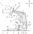
제1 실시 형태의 시중 장치(1)의 전체 구성에 대해, 도 1을 참고로 하여 설명한다. 도 1의 오른쪽 위의 화살표로 나타내듯이, 시중 장치(1)의 상하 전후를 정한다. 시중 장치(1)는, 예를 들면, 피시중자의 침대와 휠체어와의 사이의 이승(移乘)이나, 휠체어와 변좌와의 사이의 이승 등, 다른 2개소의 사이의 이승에 이용된다. 시중 장치(1)는, 피시중자의 상체를 지지하여, 좌위(座位) 자세로부터 기립 자세로의 기립 동작, 및 기립 자세로부터 좌위 자세로의 착좌(着座) 동작을 시중든다.An overall configuration of the
여기서, 기립 자세는, 엉덩이부가 좌면으로부터 떠서 다리부가 펴진 자세를 의미하고, 입위(立位) 자세 및 엉거주춤 자세를 포함한다. 즉, 기립 자세는, 상체가 대체로 직립한 입위 자세, 및 상체가 앞으로 기운 엉거주춤의 앞으로 구부린 자세 등을 포함한다. 또, 시중 장치(1)는, 이승하는 2개소가 떨어져 있는 경우에, 피시중자가 탑승하여 이동하는 용도로도 사용된다. 예를 들면, 시중 장치(1)는 피시중자가 거실로부터 화장실이나 식당 등으로 이동하는 용도로 사용된다. 시중 장치(1)는, 기대(2), 암(arm) 부재(3), 상체 지지부(4) 및 겨드랑이 지지부(5)를 포함한 지지 부재(6), 액츄에이터(actuator)(7), 및 도면 생략의 제어부 등으로 구성된다.Here, the standing posture means a posture in which the buttocks are lifted from the seating surface and the legs are stretched, and includes an upright posture and a squatting posture. That is, the standing posture includes an upright posture in which the upper body is generally upright, and a posture in which the upper body is leaned forward and bent forward. In addition, the
기대(2)는 피시중자가 탑승하는 부위이다. 기대(2)는 암 부재(3) 및 액츄에이터(7)가 조립된다. 기대(2)는, 풋 플레이트(foot plate)(20), 좌우 한 벌의 파이프 프레임(pipe frame)(21), 및 좌우 한 벌의 조립 프레임(22) 등으로 형성된다. 풋 플레이트(20)는, 금속제나 수지제의 판재로 형성되고, 바닥면 F보다도 조금 높은 위치에 수평으로 연재(延在)한다. 풋 플레이트(20)의 좌우의 가장자리는, 하방으로 절곡되어 있다. 풋 플레이트(20)는 피시중자가 다리를 싣는 부재이다.The base (2) is the part on which the fisherman rides. The
파이프 프레임(21)은 금속제의 파이프가 굽힘 가공되어 형성된다. 좌우 한 벌의 파이프 프레임(21)은, 풋 플레이트(20)의 하측에 부착되어 전방으로 연재한다. 각 파이프 프레임(21)의 전(前)부(211)는, 풋 플레이트(20)의 전방에서 상방으로 굴곡되어 있다. 한 벌의 파이프 프레임(21)의 전부(211)의 전(前)측에, 기립한 판 형상의 조립 프레임(22)이 각각 설치된다.The
좌우 한 벌의 조립 프레임(22)의 상부에, 요동 지지좌(29)가 각각 설치된다. 한 벌의 조립 프레임(22)의 하방에, 전륜(25)이 각각 설치된다. 파이프 프레임(21)의 전부(211)의 상단에, 위치 조정부(281)가 각각 설치된다. 위치 조정부(281)는, 피시중자의 체격 등에 맞추어, 무릎 댐 부재(28)의 전후 방향의 위치를 시중자 등이 조정하는 수동 조정 기구이다.A rocking support seat 29 is provided on the upper part of the left and right pair of assembly frames 22, respectively. Below the pair of assembly frames 22, the
무릎 댐 부재(28)는, 풋 플레이트(20)의 상방에 위치하고 있고, 피시중자의 무릎이 맞닿는 부위이다. 무릎 댐 부재(28)가 무릎의 위치를 정함으로써, 피시중자의 기립 동작이나 착좌 동작이 안정화된다. 무릎 댐 부재(28)는, 베이스 플레이트(282), 무릎 댐 본체(283), 및 2개의 지지 로드(rod)(284) 등으로 형성된다. 베이스 플레이트(282)는, 금속의 판재를 이용하여 좌우 방향으로 연재하도록 형성되고, 수직 방향보다도 약간 앞쪽으로 기울어져 배치된다. 무릎 댐 본체(283)는, 탄성 변형 가능한 우레탄 폼(urethan foam) 등으로 형성되고, 베이스 플레이트(282)의 후(後)측에 부착된다. 2개의 지지 로드(284)는, 금속의 봉재를 이용하여 형성되고, 베이스 플레이트(282)를 좌우의 위치 조정부(281)에 결합한다.The
풋 플레이트(20)의 앞쪽 가까운 위치에, 액츄에이터 지지재(23)가 설치된다. 풋 플레이트(20)의 앞쪽 가까운 하면의 좌우 양측에, 중륜(26)이 각각 설치된다. 풋 플레이트(20)의 후단부의 하면의 좌우 양측에, 후륜(27)이 각각 설치된다. 중륜(26) 및 후륜(27)은, 전륜(25)보다도 작은 직경이다. 전륜(25), 중륜(26), 및 후륜(27)은, 전타(轉舵)기능을 가진다. 따라서, 시중 장치(1)는, 직진 이동 및 선회 이동뿐만이 아니라, 횡 이동 및 피봇(pivot) 선회가 가능하다. 또한, 전륜(25)은 시중 장치(1)의 이동을 규제하는 락(lock) 기능을 구비한다.An
암 부재(3)는, 도 1에 나타내듯이, 측방으로부터 보아 도중에 굴절된 형상으로 형성된다. 암 부재(3)의 하부 가까이에, 좌우 한 벌의 요동축(31)이 설치된다. 한 벌의 요동축(31)은 각각 조립 프레임(22)의 요동 지지좌(29)에 요동 가능하게 지지된다. 암 부재(3)의 요동 각도 범위를 규제하기 위해, 도면 생략의 스토퍼(stopper) 기구가 요동 지지좌(29)의 근방에 설치된다. 이에 의해, 암 부재(3)는 기대(2)에 대해 상전(上前) 방향 및 하후(下後) 방향으로 요동 가능하게 되어 있다. 암 부재(3)는 피시중자의 기립 동작시에 상전 방향으로 요동한다(도 1에 있어서의 시계 회전의 요동). 또, 암 부재(3)는 피시중자의 착좌 동작 시에 하후 방향으로 요동한다.As shown in FIG. 1, the
암 부재(3)의 내부에, 도면 생략의 배터리(battery) 및 링크(link) 기구가 수납된다. 배터리는 액츄에이터(7) 및 제어부의 전원으로 된다. 암 부재(3)의 상부의 후측에 요동 지지부(부호 생략)가 설치되고, 요동 지지부에 요동 부재(32)가 설치된다. 요동 부재(32)는 암 부재(3)에 대해 요동한다. 다만, 피시중자가 지지 부재(6)에 접촉하기 이전의 초기 상태에 있어서, 요동 부재(32)는 링크 기구로 규제되어 요동하지 않는다. 또한, 본원 출원인은 링크 기구의 상세한 구성 예를 국제 공개 제2018/167856호에 개시하고 있다.A battery and a link mechanism (not shown) are housed inside the
요동 부재(32)는 후측에 베이스 플레이트(33)를 가진다. 베이스 플레이트(33)는 금속제나 수지제의 강성이 큰 판재를 이용하여 형성된다. 베이스 플레이트(33)는 핸들(34)을 전면에 가진다. 핸들(34)은, 대체로 사각형의 프레임(frame) 형상으로 형성되고, 암 부재(3)의 상방으로 연재한다. 핸들(34)은, 피시중자가 파지하는 부위임과 아울러, 시중 장치(1)를 이동시키기 위해 시중자가 파지하는 부위이기도 하다.The rocking
지지 부재(6)는 베이스 플레이트(33)의 후측에 설치된다. 지지 부재(6)는 상체 지지부(4) 및 한 벌의 겨드랑이 지지부(5)를 포함하여 구성된다. 상체 지지부(4)는 베이스 플레이트(33)의 후면에 부착된다. 상체 지지부(4)는 경질 완충 부재(41) 및 연질 완충 부재(42)가 적층되어 형성된다. 상체 지지부(4)는, 피시중자의 상반신, 주로 흉부로부터 복부의 근처를 지지한다.The
한 벌의 겨드랑이 지지부(5)는, 베이스 플레이트(33)의 좌우에 부착되고, 상체 지지부(4)의 좌우 양측에 배치된다. 겨드랑이 지지부(5)는, 둔각으로 굴곡하는 L자 형상으로 형성된다. 겨드랑이 지지부(5)의 굴곡 개소부터 상측의 기립한 상부는, 피시중자의 어깨에 맞닿는다. 겨드랑이 지지부(5)의 굴곡 개소부터 하측의 경사진 직선부는, 피시중자의 겨드랑이에 진입하여 상반신을 지지한다. 피시중자의 기립 동작시에, 겨드랑이 지지부(5)는, 피시중자를 안아 올리는 역할을 다한다. 겨드랑이 지지부(5)의 상세 구성에 대해서는 후술한다.A pair of
액츄에이터(7)는 기대(2)를 기준으로 하여 한 벌의 겨드랑이 지지부(5)를 적어도 상하 방향으로 이동시키는 구동부의 일실시 형태이다. 액츄에이터(7)는, 신축하는 직동 액츄에이터이고, 본체부(71), 가동부(72), 및 모터(73) 등으로 형성된다. 본체부(71)는, 상하로 긴 큰 직경의 원통 모양의 부재이고, 상부에 개구부를 가진다. 본체부(71)의 하단은 기대(2)의 액츄에이터 지지재(23)에 지지된다. 가동부(72)는 상하로 긴 가는 직경의 환봉 모양의 부재이다. 가동부(72)의 상단은 암 부재(3)의 링크 기구에 접속된다. 가동부(72)의 하부는 본체부(71)의 개구부에 감입(嵌入)되어 있다.The
모터(73)는 본체부(71)의 하부의 전측에 부착된다. 모터(73)는, 제어부에 의해 전류의 통전 방향이 전환 제어되고, 가동부(72)의 신장 동작 및 수축 동작을 구동한다. 이에 의해, 가동부(72)는 본체부(71)에 대해 신축 동작한다. 액츄에이터(7)는, 최소 길이로부터 소정의 도중 길이까지 신장하는 제1 신장 동작, 및 도중 길이로부터 최대 길이까지 신장하는 제2 신장 동작을 행한다.The
액츄에이터(7)의 제1 신장 동작에 의해, 지지 부재(6)는, 링크 기구를 통해 구동되고, 상전 방향으로 요동한다. 액츄에이터(7)의 제2 신장 동작에 의해, 암 부재(3)는, 링크 기구를 통해 구동되고, 상전 방향으로 요동한다. 이와 같이, 지지 부재(6)는 기대(2)에 대해 상방으로 이동하면서 전방으로도 이동한다. 이에 의해, 시중 장치(1)는 피시중자의 기립 동작을 시중든다. 또, 액츄에이터(7)의 수축 동작에 의해, 지지 부재(6)는 하방으로 이동하면서 후방으로도 이동한다. 이에 의해, 시중 장치(1)는 피시중자의 착좌 동작을 시중든다.By the first extension operation of the
도면 생략의 제어부는 조작기 및 제어 본체부 등으로 구성된다. 조작기는 액츄에이터(7)를 조작하는 상승 버튼 및 하강 버튼을 가진다. 조작기는 시중자에 의해 조작된다. 제어 본체부는 CPU(Central Processing Unit)를 가지고 소프트웨어(software)로 동작하는 컴퓨터 장치이다. 제어 본체부는, 상승 버튼 및 하강 버튼의 조작 정보에 응하여, 액츄에이터(7)에 흐르는 전류를 제어한다. 이에 의해, 액츄에이터(7)의 동작 및 정지, 및 신장 동작과 수축 동작의 전환이 제어된다.The control unit not shown in the drawing is constituted by a manipulator and a control body unit and the like. The manipulator has an up button and a down button for operating the
2. 겨드랑이 지지부(5)의 상세 구성 및 작용2. Detailed configuration and action of the armpit support (5)
다음에, 겨드랑이 지지부(5)의 상세 구성 및 작용에 대해, 도 2~도 4를 참고로 하여 설명한다. 도 2 및 도 3에 나타내듯이, 겨드랑이 지지부(5)는, 심 부재(51), 외주 부재(52), 통상(通常) 커버 부재(53), 및 마찰 저감 커버 부재(54)로 구성된다. 심 부재(51)는, 예를 들면, 금속제 또는 경질 수지제의 환봉이나 파이프가 L자 형상으로 굴곡되어 형성된다. 심 부재(51)의 굴곡 개소부터 상측의 상부, 및 굴곡 개소부터 하측의 직선부는, 겨드랑이 지지부(5)의 상부 및 직선부에 대응한다. 심 부재(51)는 피시중자의 체중을 지지할 수 있는 충분한 기계적 강도를 가진다.Next, the detailed structure and action of the
외주 부재(52)는, 탄성 변형이 가능한 쿠션(cushion)재를 이용하고, 심 부재(51)의 적어도 하측의 직선부의 외주를 덮는 두꺼운 통 형상으로 형성되어 있다. 외주 부재(52)를 형성하는 쿠션재의 재질로서 에틸렌 프로필렌(ethylene propylene) 고무를 원료로 하는 스펀지(sponge) 고무를 예시할 수 있다. 쿠션재로 이루어지는 외주 부재(52)는, 피시중자 M으로부터 작용하는 하중에 대해 용이하게 압축 변형한다. 외주 부재(52)는, 심 부재(51)에 대한 접착 등의 구속이 되어도 좋고, 심 부재(51)에 대해 소정의 각도 범위 내에서 회전 가능하게 되어도 좋다.The outer
통상 커버 부재(53)는, 예를 들면 합성 피혁을 이용하여 형성된다. 통상 커버 부재(53)는 외주 부재(52)의 외주를 덮는 통 형상으로 형성되어 있다. 통상 커버 부재(53)는 외주 부재(52)에 접착되어 외주 부재(52)와 함께 변형 가능하다. 통상 커버 부재(53)는 심 부재(51) 및 외주 부재(52)의 아래의 후측의 단면을 덮고 있어도 좋다.Usually, the
마찰 저감 커버 부재(54)는, 대략 사각형의 합성 수지제 시트(sheet), 예를 들면 폴리프로필렌(polypropylene)제 시트를 이용하여 형성된다. 도 3에 나타내듯이, 마찰 저감 커버 부재(54)는, 한 벌의 겨드랑이 지지부(5)의 상측으로부터 서로 마주 보는 내측을 경유하여 하측까지 연재한다. 마찰 저감 커버 부재(54)는 통상 커버 부재(53)의 외면에 접착되거나 또는 꿰매어 붙여져 배치된다.The friction
상기의 구성에 의하면, 마찰 저감 커버 부재(54)는 피시중자의 옆구리부에 접촉한다. 또, 통상 커버 부재(53)는 피시중자의 적어도 겨드랑이 및 상완부에 접촉한다. 여기서, 통상 커버 부재(53)의 표면은, 마찰 저감 커버 부재(54)와 비교하여 상대적으로 거칠고, 상대적으로 큰 마찰 계수를 가진다. 반대로, 마찰 저감 커버 부재(54)의 표면은, 상대적으로 매끄럽고, 상대적으로 작은 마찰 계수를 가진다. 따라서, 통상 커버 부재(53)는 피시중자의 적어도 겨드랑이 및 상완부에 접촉하는 통상 표면부를 구성한다. 또, 마찰 저감 커버 부재(54)는 통상 표면부보다도 작은 마찰 계수를 가지고 피시중자의 옆구리부에 접촉하는 마찰 저감 표면부를 구성한다.According to the configuration described above, the friction
도 4에 나타내는 피시중자 H의 기립 동작의 초기 상태에 있어서, 겨드랑이 지지부(5)는 피시중자 H의 겨드랑이의 하방의 옆구리부와 상완부의 사이에 위치한다. 시중 장치(1)에 의한 기립 동작의 시중이 시작되면, 겨드랑이 지지부(5)는 상방으로 이동하면서 피시중자 H를 안아 올린다. 이 때, 겨드랑이 지지부(5)는, 옆구리부에 접촉하면서 상승하여, 마찰력 F1이 발생한다. 이 마찰력 F1에 의해, 외주 부재(52)는, 마찰 저감 커버 부재(54)가 하강하는 회전 방향 R1(도 3 참조)으로 비틀림 변형하고, 압축 변형도 수반한다. 또, 피시중자 H의 옆구리부에는, 끌어올리는 방향의 마찰력 F1이 작용한다. 그래도, 옆구리부에 접촉하는 것은 마찰 저감 커버 부재(54)(마찰 저감 표면부)이기 때문에, 발생하는 마찰력 F1이 경감된다.In the initial state of the standing operation of the person H shown in FIG. 4, the
한편, 통상 커버 부재(53)는, 적당한 면압 및 마찰력으로 피시중자 H의 겨드랑이 및 상완부에 접촉하므로, 안아 올리는 힘이 확보된다. 따라서, 겨드랑이 지지부(5)는 피시중자 H를 안정적으로 안아 올릴 수가 있다. 만일, 통상 커버 부재(53)를 이용하지 않고, 외주 부재(52)의 전체 둘레를 마찰 저감 커버 부재(54)로 덮으면, 옆구리부나 상완부의 미끄럼 움직임이 과대하게 되고, 피시중자 H의 자세가 불안정화 할 우려가 생긴다.On the other hand, since the
제1 실시 형태의 시중 장치(1)에 의하면, 겨드랑이 지지부(5)의 표면 중 피시중자 H의 옆구리부에 접촉하는 부분은 마찰 저감 커버 부재(54)(마찰 저감 표면부)로 된다. 이 때문에, 마찰력 F1에 의해 생기는 피시중자 H의 아픔이 경감된다. 따라서, 쾌적한 사용감을 실현한 시중 장치(1)를 제공할 수가 있다.According to the
또한, 통상 커버 부재(53) 및 마찰 저감 커버 부재(54)의 재질의 조합은, 상기한 예로 한정되지 않고, 다른 재질의 조합이라도 좋다. 또, 마찰 저감 커버 부재(54)는, 통상 커버 부재(53)의 외면에 겹쳐서 배치되는 2층 구성이 아니고, 통상 커버 부재(53)에 형성된 대략 사각형의 절결부에 배치되는 1층 구성이라도 좋다. 또한, 통상 커버 부재(53)가 생략되고, 외주 부재(52)의 외면의 일부에 직접적으로 마찰 저감 커버 부재(54)가 접착되어 있어도 좋다. 이 경우, 마찰 저감 커버 부재(54)의 표면의 마찰 계수는, 외주 부재(52)의 외면의 마찰 계수보다도 작게 설정된다.In addition, the combination of the materials of the
3. 제2 실시 형태의 시중 장치(1)의 겨드랑이 지지부(5A)3.
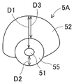
다음에, 제2 실시 형태의 시중 장치(1)에 대해, 도 5 및 도 6을 참고로 하여, 제1 실시 형태와 다른 점을 주로 설명한다. 제2 실시 형태에 있어서, 겨드랑이 지지부(5A) 이외의 구성은, 제1 실시 형태와 같다. 도 5에 나타내듯이, 제2 실시 형태의 겨드랑이 지지부(5A)는, 심 부재(51), 중간 부재(55), 및 외주 부재(52)로 구성된다.Next, with reference to FIG. 5 and FIG. 6, about the
심 부재(51)는 금속제 또는 경질 수지제의 환봉이나 파이프를 이용하여 형성된다. 중간 부재(55)는, 외주 부재(52)보다도 경질이지만 탄성 변형이 가능한 재질, 예를 들면 딱딱한 스펀지 고무를 이용하고, 심 부재(51)의 외주를 덮는 두꺼운 통 형상으로 형성되어 있다. 외주 부재(52)는, 쿠션재를 이용하고, 중간 부재(55)의 외주 중 상측을 덮고, 하측을 덮지 않는 형상으로 형성되어 있다. 또한, 중간 부재(55)는, 외주 부재(52)와 같은 재질로 형성되어도 좋고, 또는 외주 부재(52)와 일체로 형성되어도 좋다. 또, 겨드랑이 지지부(5A)의 옆구리부에 접촉하는 내측과 외측이 대칭 구조일 필요는 없다.The
본 제2 실시 형태에 있어서, 중간 부재(55)는, 심 부재(51)를 덮으면서 탄성 변형이 가능한 외주 부재(52)의 일부로 되어 있다. 이에 의하면, 중간 부재(55)를 포함한 외주 부재(52)의 중심보다도 하방에, 심 부재(51)가 배치된 것으로 된다. 또, 중간 부재(55)를 포함한 외주 부재(52)의 상측의 두께 D1이 하측의 두께 D2보다 크다. 또한, 상측의 두께 D1은, 대략 회전 대칭 단면을 가지는 종래의 겨드랑이 지지부의 그것보다도 크게 설정되어 있다.In the second embodiment, the
도 6에 나타내는 피시중자 H의 기립 동작의 도중 상태에 있어서, 피시중자 H의 체중에 의한 하중 W1이 겨드랑이 지지부(5A)에 작용한다. 이 반력으로서, 겨드랑이 지지부(5A)는, 피시중자 H의 겨드랑이를 밀어 올리므로, 피시중자 H는 겨드랑이에 압박감을 가진다. 그래도, 중간 부재(55)를 포함한 외주 부재(52)의 상측의 두께 D1이 크기 때문에, 종래보다도 큰 변형이 발생하여 압박감이 억제된다.In the state in the middle of the standing motion of the person H shown in FIG. 6 , the load W1 due to the weight of the person H acts on the
제2 실시 형태의 시중 장치(1)에 의하면, 겨드랑이 지지부(5A)를 구성하는 외주 부재(52)의 상측의 두께 D1을 종래보다도 크게 하여, 겨드랑이를 밀어 올리는 압박감의 발생을 억제할 수 있다. 이 때문에, 피시중자 H의 아픔이 경감된다. 따라서, 쾌적한 사용감을 실현한 시중 장치(1)를 제공할 수가 있다.According to the
또한, 중간 부재(55)를 포함한 외주 부재(52)의 두께를 전체 둘레에 걸쳐 일률적으로 크게 하는 것이 아니고, 상측의 두께 D1을 크게, 하측의 두께 D2를 작게 한다. 이에 의해, 겨드랑이 지지부(5A)의 대형화를 억제할 수가 있다. 이에 더하여, 하측의 두께 D2를 작게 함으로써, 겨드랑이 지지부(5A)와 바닥면 F와의 사이에 넓은 스페이스(space)를 확보할 수 있어 휠체어의 진입이 용이하게 된다. 이에 의해, 피시중자 H는 휠체어로부터 풋 플레이트(20)로 용이하게 이승할 수가 있어 사용 쾌적성이 향상된다.In addition, the thickness of the outer
또, 중간 부재(55)는, 탄성 변형하지 않는 솔리드(solid)한 재질로 형성하고, 심 부재(51)의 일부로 할 수가 있다. 이 변형 태양에 있어서, 외주 부재(52)는, 중간 부재(55)를 포함한 심 부재(51)의 상측을 덮고, 하측을 덮지 않는다. 다만, 외주 부재(52)의 상측의 두께 D3은, 종래의 겨드랑이 지지부의 그것보다도 크게 설정된다.In addition, the
4. 제3 실시 형태의 시중 장치(1)4. Commercial apparatus (1) of the third embodiment
다음에, 제3 실시 형태의 시중 장치(1)에 대해, 도 7~도 9를 참고로 하여, 제1 및 제2 실시 형태와 다른 점을 주로 설명한다. 제3 실시 형태의 시중 장치(1)는, 기대(2), 암 부재(3), 상체 지지부(4) 및 겨드랑이 지지부(5B)를 포함한 지지 부재(6), 액츄에이터(7), 도면 생략의 제어부에 더하여, 제한 벨트(81) 및 조정 버클(83)을 구비한다. 도 8에 있어서, 상체 지지부(4) 및 외주 부재(52)는, 도시 생략되어 있다.Next, about the
도 8에 나타내듯이, 겨드랑이 지지부(5B)를 구성하는 심 부재(51)는, 기립한 전(前)부의 내측에 부착판(56)을 가진다. 부착판(56)은 베이스 플레이트(33)의 후면에 지근(至近)하여 배치된다. 부착판(56)의 대체로 중앙에, 소정 위치(57)가 설정된다. 소정 위치(57)는 베이스 플레이트(33)에 의해 요동 가능하게 지지되어 있다. 이에 의해, 한 벌의 심 부재(51) 및 겨드랑이 지지부(5B)는, 화살표 M1로 나타내듯이, 소정 위치(57)를 요동 중심으로 하여 서로 접근하는 방향으로 요동 가능하게 된다. 또, 부착판(56)의 아래 가장자리의 심 부재(51)에 가까운 위치에 제한 위치(58)가 설정된다.As shown in FIG. 8, the
도 7 및 도 8에 나타내듯이, 대체로 사각형의 프레임 형상의 핸들(34)의 상부의 중앙에, 정점 위치(82)가 설정된다. 제한 벨트(81)는, 일방의 겨드랑이 지지부(5B)의 제한 위치(58)와, 타방의 겨드랑이 지지부(5B)의 제한 위치(58)를 묶으면서, 정점 위치(82)에 슬라이딩(sliding) 가능하게 되접어 꺾여 있다. 제한 벨트(81)는, 폭 방향으로 신축 가능하지만, 길이 방향으로는 신축하지 않는다. 또한, 핸들(34)은, 겨드랑이 지지부(5B)와 일체적으로 이동 및 요동하므로, 도 7 및 도 8에 나타낸 위치 관계는 항상 유지된다.7 and 8, the
제한 벨트(81)는, 팽팽하게 텐션(tension)이 생긴 상태로, 좌우의 제한 위치(58)를 규제하고, 부착판(56) 및 심 부재(51)의 요동 범위를 제한한다. 이에 의해, 겨드랑이 지지부(5B)의 요동 범위가 제한된다. 즉, 제한 벨트(81)는, 한 벌의 겨드랑이 지지부(5B)가 서로 접근할 때의 최접근 거리를 제한하는 기능을 가진다. 또, 제한 벨트(81)는, 한 벌의 겨드랑이 지지부(5B)가 서로 이간하는 방향에 관하여, 느슨함이 생길 뿐이고, 제한 기능을 가지지 않는다. 제한 벨트(81)는, 한 벌의 겨드랑이 지지부(5B)가 서로 접근하는 방향의 요동 범위 또는 이동 범위를 제한하는 제한 기구의 한 형태이다.The limiting
제한 벨트(81)의 일방의 제한 위치(58)와 정점 위치(82)의 사이에, 조정 버클(83)이 삽입되어 있다. 조정 버클(83)은 제한 벨트(81)의 길이를 조정하는 기능을 가진다. 시중자 등은 피시중자의 체격에 응하여 조정 버클(83)을 조작하여 제한 벨트(81)의 길이를 조정한다. 조정 버클(83)은, 피시중자의 체격에 응하여, 제한 기구(제한 벨트(81))가 제한하는 요동 범위 또는 이동 범위를 조정하는 조정부의 한 형태이다.An
도 9에 나타내는 피시중자 H의 기립 동작의 초기 상태에 있어서, 겨드랑이 지지부(5B)는, 피시중자 H의 겨드랑이의 하방의 옆구리부와 상완부의 사이에 위치한다. 이 때, 한 벌의 겨드랑이 지지부(5B)는, 피시중자 H의 옆구리부를 양측으로부터 끼워 넣기 때문에, 압박력 F2가 발생한다. 그래도, 제한 벨트(81)에 의해 한 벌의 겨드랑이 지지부(5B)의 최접근 거리가 제한되므로, 압박력 F2가 경감된다.In the initial state of the standing motion of the person H shown in FIG. 9, the
또, 피시중자 H가 몸집이 작은 경우에, 시중자 등은, 제한 벨트(81)를 길게 조정하여, 한 벌의 겨드랑이 지지부(5B)의 최접근 거리를 작게 설정한다. 한편, 피시중자 H가 몸집이 큰 경우에, 시중자 등은, 제한 벨트(81)를 짧게 조정하여, 한 벌의 겨드랑이 지지부(5B)의 최접근 거리를 크게 설정한다. 이에 의하면, 제한 벨트(81)의 길이를 조정함으로써, 한 벌의 겨드랑이 지지부(5B)의 최접근 거리를 피시중자 H의 체격에 적합시킬 수가 있고, 언제라도 압박력 F2를 적정하게 경감하는 효과가 발생한다.Moreover, when the person H is small, the attendant or the like adjusts the
제3 실시 형태의 시중 장치(1)에 의하면, 한 벌의 겨드랑이 지지부(5B)가 서로 접근했을 때의 최접근 거리가 제한된다. 이 때문에, 피시중자 H의 옆구리부를 양측으로부터 끼워 넣는 압박력 F2가 억제되어 피시중자 H의 아픔이 경감된다. 따라서, 쾌적한 사용감을 실현한 시중 장치(1)를 제공할 수가 있다.According to the
또한 좌우의 겨드랑이 지지부(5B)의 제한 위치(58)와 정점 위치(82)를 개별적으로 묶는 좌우 한 벌의 제한 벨트를 이용해도 좋다. 이 태양에서는, 한 벌의 제한 벨트의 각각에 조정 버클(83)을 설치한다. 또, 조정 버클(83)을 생략하는 것이 가능하다. 또한, 한 벌의 겨드랑이 지지부(5B)는, 요동하는 것이 아니고, 평행 상태를 유지하면서 서로 접근 또는 이간하는 방향으로 이동 가능이라도 좋다. 이 태양에 있어서, 제한 벨트(81)에 대신하는 제한 기구는, 한 벌의 겨드랑이 지지부(5B)가 서로 접근하는 방향의 이동 범위를 제한한다.Moreover, you may use the right and left pair of restraint belts which individually bind the
5. 제4 실시 형태의 시중 장치(1)5. Commercial apparatus (1) of the fourth embodiment
다음에, 제4 실시 형태의 시중 장치(1)에 대해, 도 10을 참고로 하여, 제1~제3 실시 형태와 다른 점을 주로 설명한다. 도 10에 있어서, 상체 지지부(4) 및 외주 부재(52)는, 도시 생략되어 있다. 제4 실시 형태의 시중 장치(1)는, 제3 실시 형태와 마찬가지로 심 부재(51) 및 겨드랑이 지지부(5B)가 요동하고, 제3 실시 형태와 다른 제한 기구 및 조정부를 구비한다. 제한 기구는, 한 벌의 제한 핀(pin)(86)과 제한 로드(rod)(87)에 의해 구성된다. 조정부로서, 로드 위치 조정부(88)가 설치된다.Next, about the
한 벌의 제한 핀(86)은, 제3 실시 형태의 제한 위치(58)에 대신하여, 좌우의 부착판(56)의 아래 가장자리 가까이의 심 부재(51)에 가까운 위치에 설치된다. 제한 로드(87)는, 좌우의 부착판(56)의 후면에 걸쳐 놓여져 설치되고, 제한 핀(86)보다도 하측에 배치된다. 겨드랑이 지지부(5B) 및 심 부재(51)가 서로 접근하는 방향 M1로 요동하는 도중에, 제한 핀(86)이 제한 로드(87)의 표면에 맞닿아 요동이 제한된다.A pair of limiting
제한 로드(87)의 좌우 방향의 중앙 부분은, 로드 위치 조정부(88)에 의해 지지되고, 상하 방향으로 슬라이드 이동 가능하게 되어 있다. 로드 위치 조정부(88)는 베이스 플레이트(33)를 관통하여 설치된다. 로드 위치 조정부(88)는 제한 로드(87)의 상하 방향의 위치를 조정하는 기능을 가진다. 시중자 등은, 베이스 플레이트(33)의 전측으로부터 로드 위치 조정부(88)를 조작하여, 화살표 M2로 나타내듯이, 제한 로드(87)의 상하 방향의 위치를 조정할 수가 있다.A central portion of the limiting
구체적으로, 피시중자가 몸집이 작은 경우에, 시중자 등은, 제한 로드(87)의 위치를 낮게 조정하여, 한 벌의 겨드랑이 지지부(5B)의 최접근 거리를 작게 설정한다. 한편, 피시중자가 몸집이 큰 경우에, 시중자 등은, 제한 로드(87)의 위치를 조금 높게 조정하여, 한 벌의 겨드랑이 지지부(5B)의 최접근 거리를 크게 설정한다. 이에 의하면, 제3 실시 형태와 마찬가지로, 한 벌의 겨드랑이 지지부(5B)의 최접근 거리를 피시중자의 체격에 적합시킬 수가 있어 언제라도 압박력을 경감하는 효과가 발생한다.Specifically, when the target person is small, the attendant or the like adjusts the position of the limiting
6. 겨드랑이 지지 어시스트 기구(9)6. Armpit Support Assist Mechanism (9)
다음에, 제1~제4 실시 형태의 시중 장치(1)에 추가할 수가 있는 겨드랑이 지지 어시스트 기구(9)에 대해, 도 11을 참고로 하여 설명한다. 겨드랑이 지지 어시스트 기구(9)는, 베이스 플레이트(33)의 전면 또는 후면에 설치된다. 도 11에 나타내듯이, 겨드랑이 지지 어시스트 기구(9)는, 한 벌의 겨드랑이 지지부(5B)(5, 5A)에 작용하는 하향의 하중 W2에 응하여, 한 벌의 겨드랑이 지지부(5B)(5, 5A)를 서로 접근하는 방향 M3으로 요동 또는 이동시킨다. 이에 의하면, 피시중자가 한 벌의 겨드랑이 지지부(5B)(5, 5A)에 기댔을 때에, 한 벌의 겨드랑이 지지부(5B)(5, 5A)는 서로 접근하여 확실하게 피시중자를 지지한다.Next, the armpit support-
본원 출원인은, 겨드랑이 지지 어시스트 기구(9)에 적용 가능한 기구의 일례를, 국제 공개 2015/011838호에 보유 위치 조정 기구로 이름 붙여 개시하고 있다. 또, 제3 실시 형태의 시중 장치(1)에 겨드랑이 지지 어시스트 기구(9)를 추가한 태양에서는, 피시중자의 자세의 좌우의 언밸런스(unbalance)를 억제하는 작용이 있다. 상술하면, 피시중자가 일방의 겨드랑이 지지부(5B)에 기댔을 때에, 그 겨드랑이 지지부(5B)는 요동하지만, 제한 벨트(81)가 팽팽하게 텐션이 생긴다. 이에 의해, 일방의 겨드랑이 지지부(5B)의 요동 범위가 제한되고, 타방의 겨드랑이 지지부(5B)와의 언밸런스가 억제된다. 결과적으로, 시중 장치(1)는 피시중자의 자세의 좌우의 언밸런스를 억제할 수가 있다.The applicant of this application names an example of the mechanism applicable to the armpit support-
7. 실시 형태의 변형 및 응용7. Modifications and Applications of Embodiments
또한 제1 실시 형태와 제2 실시 형태를 조합하여 실시할 수가 있다. 또, 제1 및 제2 실시 형태는, 제3 또는 제4 실시 형태와 조합할 수가 있다. 환언하면, 제1 및 제2 실시 형태의 시중 장치(1)는, 제3 또는 제4 실시 형태에 기재된 제한 기구 및 조정부를 구비해도 좋다. 그 외에도, 제1~제4 실시 형태는 여러 가지 변형이나 응용이 가능하다.Further, the first embodiment and the second embodiment can be combined and implemented. In addition, the first and second embodiments can be combined with the third or fourth embodiment. In other words, the
1:시중 장치
2:기대
20:풋 플레이트(foot plate)
21:파이프 프레임(pipe frame)
22:조립 프레임
3:암(arm) 부재
33:베이스 플레이트(base plate)
34:핸들(handle)
4:상체 지지부
5, 5A, 5B:겨드랑이 지지부
51:심(芯) 부재
52:외주(外周) 부재
53:통상(通常) 커버 부재
54:마찰 저감 커버 부재
55:중간 부재
56:부착판
57:소정 위치
58:제한 위치
6:지지 부재
7:액츄에이터(actuator)
81:제한 벨트(belt)
82:정점 위치
83:조정 버클(buckle)
86:제한 핀(pin)
87:제한 로드(rod)
88:로드 위치 조정부
9:겨드랑이 지지 어시스트(assist) 기구1: Marketing device 2: Expectation
20: foot plate
21: pipe frame
22: Assembly frame 3: Arm member
33: base plate
34: handle 4: upper body support
5, 5A, 5B: armpit support
51: core member 52: outer periphery member
53: Normal cover member
54: Friction reduction cover member
55: Intermediate member 56: Mounting plate
57: Predetermined position 58: Restricted position
6: support member
7: Actuator
81: Restriction belt 82: Vertex position
83: adjustment buckle 86: limit pin
87: limiting rod 88: rod position adjustment part
9: Armpit support assist mechanism
Claims (15)
피시중자의 좌우의 겨드랑이를 각각 지지하는 한 벌의 겨드랑이 지지부와,
상기 기대를 기준으로 하여 한 벌의 상기 겨드랑이 지지부를 적어도 상하 방향으로 이동시키는 구동부를 구비하는 시중 장치로서,
상기 겨드랑이 지지부는, 상기 피시중자의 적어도 상기 겨드랑이 및 상완부에 접촉하는 통상 표면부와, 상기 통상 표면부보다도 작은 마찰 계수를 가지고 상기 피시중자의 옆구리부에 접촉하는 마찰 저감 표면부를 가지는 시중 장치.anticipation and
A pair of armpit support parts that support the left and right armpits of the fisherman, respectively,
As a commercial device having a driving unit for moving the pair of armpit support at least in an up-down direction based on the expectation,
The armpit support part has a normal surface part in contact with at least the armpit and upper arm of the target person, and a friction reducing surface part having a friction coefficient smaller than that of the normal surface part and contacting the side part of the target person.
상기 겨드랑이 지지부는,
심 부재와,
상기 심 부재를 덮으면서 탄성 변형이 가능한 외주 부재와,
상기 외주 부재를 덮고, 상기 통상 표면부를 구성하는 통상 커버 부재와,
상기 외주 부재를 덮고, 상기 마찰 저감 표면부를 구성하는 마찰 저감 커버 부재를 가지는 시중 장치.According to claim 1,
The armpit support portion,
heart absent,
an outer peripheral member capable of elastic deformation while covering the core member;
a cylindrical cover member covering the outer peripheral member and constituting the cylindrical surface portion;
and a friction reducing cover member covering the outer circumferential member and constituting the friction reducing surface portion.
상기 마찰 저감 커버 부재는, 상기 통상 커버 부재의 외면에 겹쳐서 배치되는 시중 장치.3. The method of claim 2,
The friction reduction cover member is a commercial device disposed to overlap an outer surface of the normal cover member.
상기 통상 커버 부재는, 그 표면이 상대적으로 거친 합성 피혁이고, 상기 마찰 저감 커버 부재는, 그 표면이 상대적으로 매끄러운 합성 수지제 시트인 시중 장치.4. The method of claim 2 or 3,
The normal cover member is a synthetic leather having a relatively rough surface, and the friction reducing cover member is a synthetic resin sheet having a relatively smooth surface.
상기 겨드랑이 지지부는,
심 부재와,
상기 심 부재를 덮으면서 탄성 변형이 가능하고, 그 중심보다도 하방에 상기 심 부재가 배치되는 외주 부재를 가지는 시중 장치.5. The method according to any one of claims 1 to 4,
The armpit support portion,
heart absent,
A commercial apparatus having an outer peripheral member capable of elastically deforming the core member while covering the core member, wherein the core member is disposed below the center thereof.
피시중자의 좌우의 겨드랑이를 각각 지지하는 한 벌의 겨드랑이 지지부와,
상기 기대를 기준으로 하여, 한 벌의 상기 겨드랑이 지지부를 적어도 상하 방향으로 이동시키는 구동부를 구비하는 시중 장치로서,
상기 겨드랑이 지지부는,
심 부재와,
상기 심 부재를 덮으면서 탄성 변형이 가능하고, 그 중심보다도 하방에 상기 심 부재가 배치되는 외주 부재를 가지는 시중 장치.anticipation and
A pair of armpit support parts that support the left and right armpits of the fisherman, respectively,
Based on the expectation, as a commercial device having a driving unit for moving the pair of armpit support at least in the vertical direction,
The armpit support portion,
heart absent,
A commercial apparatus having an outer peripheral member capable of elastically deforming the core member while covering the core member, wherein the core member is disposed below the center thereof.
상기 외주 부재는, 상기 심 부재를 덮는 통 형상으로 형성되고, 상측의 두께가 하측의 두께보다 큰 시중 장치.7. The method of claim 5 or 6,
The outer circumferential member is formed in a cylindrical shape that covers the core member, and the thickness of the upper side is greater than the thickness of the lower side.
상기 외주 부재는, 상기 심 부재의 상측을 덮고, 상기 심 부재의 하측을 덮지 않는 시중 장치.7. The method of claim 5 or 6,
The outer peripheral member covers the upper side of the shim member, but does not cover the lower side of the shim member.
한 벌의 상기 겨드랑이 지지부는, 서로 접근 또는 이간하는 방향으로 요동 가능 또는 이동 가능하고,
한 벌의 상기 겨드랑이 지지부가 서로 접근하는 방향의 요동 범위 또는 이동 범위를 제한하는 제한 기구를 더 구비하는 시중 장치.9. The method according to any one of claims 1 to 8,
The armpit support part of a pair is swingable or movable in a direction approaching or separating from each other,
A commercial device further comprising a limiting mechanism for limiting a swing range or a range of movement in a direction in which the pair of armpit supports approach each other.
피시중자의 좌우의 겨드랑이를 각각 지지함과 아울러, 서로 접근 또는 이간하는 방향으로 요동 가능 또는 이동 가능한 한 벌의 겨드랑이 지지부와,
상기 기대를 기준으로 하여, 한 벌의 상기 겨드랑이 지지부를 적어도 상하 방향으로 이동시키는 구동부와,
한 벌의 상기 겨드랑이 지지부가 서로 접근하는 방향의 요동 범위 또는 이동 범위를 제한하는 제한 기구를 구비하는 시중 장치.anticipation and
A pair of axillary support parts that support each other's left and right armpits, and that can swing or move in a direction to approach or separate from each other,
Based on the expectation, a driving unit for moving the pair of the armpit support at least in the vertical direction;
A commercial device having a limiting mechanism for limiting a swing range or a range of movement in a direction in which the pair of the armpit support parts approach each other.
상기 겨드랑이 지지부의 소정 위치가 요동 가능하게 지지되어 있고,
상기 제한 기구는, 상기 겨드랑이 지지부의 상기 소정 위치 이외의 제한 위치와, 상기 겨드랑이 지지부와 일체적으로 이동하는 부재에 설치된 정점 위치를 묶는 제한 벨트인 시중 장치.11. The method of claim 9 or 10,
A predetermined position of the armpit support part is supported so that it can swing,
and the restriction mechanism is a restriction belt that binds a restriction position other than the predetermined position of the armpit support part and an apex position provided on a member that moves integrally with the armpit support part.
상기 제한 벨트는, 일방의 상기 겨드랑이 지지부의 상기 제한 위치와, 타방의 상기 겨드랑이 지지부의 상기 제한 위치를 묶으면서, 상기 정점 위치에서 슬라이딩 가능하게 되접어 꺾이는 시중 장치.12. The method of claim 11,
The restraint belt is slidably folded back at the apex position while binding the limiting position of the one side of the armpit support and the limiting position of the other side of the armpit support.
상기 피시중자의 체격에 응하여, 상기 제한 기구가 제한하는 상기 요동 범위 또는 상기 이동 범위를 조정하는 조정부를 더 구비하는 시중 장치.13. The method according to any one of claims 9 to 12,
and an adjustment unit for adjusting the swinging range or the moving range restricted by the limiting mechanism in response to the physique of the target person.
상기 피시중자의 체격에 응하여 상기 제한 벨트의 길이를 조정하는 조정 버클을 더 구비하는 시중 장치.13. The method of claim 11 or 12,
A commercial device further comprising an adjustment buckle for adjusting the length of the restraining belt in response to the physique of the person being fished.
한 벌의 상기 겨드랑이 지지부에 작용하는 하향의 하중에 응하여, 한 벌의 상기 겨드랑이 지지부를 서로 접근하는 방향으로 요동 또는 이동시키는 겨드랑이 지지 어시스트 기구를 더 구비하는 시중 장치.
15. The method according to any one of claims 1 to 14,
In response to a downward load acting on the pair of the armpit support, a commercial device further comprising an armpit support assist mechanism for swinging or moving the pair of the armpit support in a mutually approaching direction.
Applications Claiming Priority (1)
| Application Number | Priority Date | Filing Date | Title |
|---|---|---|---|
| PCT/JP2020/019829 WO2021234827A1 (en) | 2020-05-19 | 2020-05-19 | Assistive device |
Publications (1)
| Publication Number | Publication Date |
|---|---|
| KR20220143101A true KR20220143101A (en) | 2022-10-24 |
Family
ID=78708420
Family Applications (1)
| Application Number | Title | Priority Date | Filing Date |
|---|---|---|---|
| KR1020227032230A KR20220143101A (en) | 2020-05-19 | 2020-05-19 | market device |
Country Status (4)
| Country | Link |
|---|---|
| JP (1) | JP7420931B2 (en) |
| KR (1) | KR20220143101A (en) |
| CN (1) | CN115484914A (en) |
| WO (1) | WO2021234827A1 (en) |
Citations (1)
| Publication number | Priority date | Publication date | Assignee | Title |
|---|---|---|---|---|
| WO2018179294A1 (en) | 2017-03-30 | 2018-10-04 | 株式会社Fuji | Assistance device |
Family Cites Families (19)
| Publication number | Priority date | Publication date | Assignee | Title |
|---|---|---|---|---|
| JP2660144B2 (en) * | 1992-10-29 | 1997-10-08 | 繁雄 石岡 | Device with means of transport for nursing care |
| JP2005192779A (en) * | 2004-01-07 | 2005-07-21 | Sakai Medical Co Ltd | Body holder |
| US20070074749A1 (en) * | 2005-10-05 | 2007-04-05 | Jones Kathleen M | Padding for crutches |
| JP2008073485A (en) * | 2006-09-20 | 2008-04-03 | Junko Ujihara | Support tool for crutch |
| US8157757B2 (en) * | 2010-03-08 | 2012-04-17 | Sastry K Ganti | Special bed to self induce body traction |
| JP2012187284A (en) * | 2011-03-10 | 2012-10-04 | Yoshiro Nakamatsu | Antigravity longitudinal extension walking device |
| US20150182403A1 (en) * | 2013-01-18 | 2015-07-02 | Yi-Je Lim | A Mobile Robotic Lifting and Transferring System for Bariatric Patients |
| CN203790177U (en) * | 2014-04-09 | 2014-08-27 | 曹妍妍 | Split type easily operated orthopedic care bed |
| US10821043B2 (en) * | 2014-11-14 | 2020-11-03 | Qfix Systems, Llc | Patient transfer device and associated systems and methods |
| EP3323399B1 (en) * | 2015-07-14 | 2021-02-17 | FUJI Corporation | Patient care robot |
| JP7007912B2 (en) * | 2015-10-06 | 2022-01-25 | 株式会社Fuji | Caregiving device |
| CN109069334A (en) * | 2016-05-17 | 2018-12-21 | 株式会社富士 | Jie helps device |
| WO2017205849A1 (en) * | 2016-05-27 | 2017-11-30 | Evelyn & Bobbie, LLC | Garment frame, support structure, casing, and housing |
| EP3476795B1 (en) * | 2016-06-28 | 2023-08-02 | Kubota Corporation | Assist suit |
| JP6704508B2 (en) * | 2017-03-31 | 2020-06-03 | 株式会社Fuji | Assistance device |
| JP6767566B2 (en) * | 2017-03-31 | 2020-10-14 | 株式会社Fuji | Assistance device |
| CN209827313U (en) * | 2018-12-12 | 2019-12-24 | 广东东品美容医疗科技有限公司 | Multifunctional physiotherapy couch |
| CN210189813U (en) * | 2019-07-09 | 2020-03-27 | 萍乡学院 | Auxiliary standing robot |
| CN110974575A (en) * | 2019-12-25 | 2020-04-10 | 首都医科大学宣武医院 | Auxiliary supporting device for patient with mobility disability and using method thereof |
-
2020
- 2020-05-19 WO PCT/JP2020/019829 patent/WO2021234827A1/en active Application Filing
- 2020-05-19 JP JP2022523799A patent/JP7420931B2/en active Active
- 2020-05-19 CN CN202080100210.1A patent/CN115484914A/en active Pending
- 2020-05-19 KR KR1020227032230A patent/KR20220143101A/en unknown
Patent Citations (1)
| Publication number | Priority date | Publication date | Assignee | Title |
|---|---|---|---|---|
| WO2018179294A1 (en) | 2017-03-30 | 2018-10-04 | 株式会社Fuji | Assistance device |
Also Published As
| Publication number | Publication date |
|---|---|
| JPWO2021234827A1 (en) | 2021-11-25 |
| WO2021234827A1 (en) | 2021-11-25 |
| JP7420931B2 (en) | 2024-01-23 |
| CN115484914A (en) | 2022-12-16 |
Similar Documents
| Publication | Publication Date | Title |
|---|---|---|
| EP1401306B1 (en) | Seats | |
| US8177299B2 (en) | Chair more comfortable when seated in optimum posture while reclining | |
| JP5594366B2 (en) | Vehicle seat and rigidity setting method for vehicle seat | |
| JP6714766B2 (en) | Assistance device | |
| JP4919633B2 (en) | wheelchair | |
| JP6704508B2 (en) | Assistance device | |
| KR102359173B1 (en) | market device | |
| US8894591B2 (en) | Walking assistance device | |
| JPH10151033A (en) | Chair | |
| WO2007080667A1 (en) | Seat structure | |
| KR20220143101A (en) | market device | |
| WO2018179431A1 (en) | Assistance device | |
| KR102490709B1 (en) | market device | |
| WO2018179294A1 (en) | Assistance device | |
| JP6942592B2 (en) | Chair | |
| JP6923398B2 (en) | Cushions and wheelchairs | |
| JP2009219702A (en) | Reclining seat | |
| JPS6122501Y2 (en) | ||
| JP6898507B2 (en) | Assistance device | |
| JPH0527090Y2 (en) | ||
| JPH0529651Y2 (en) | ||
| JPWO2020208700A1 (en) | Caregiving device | |
| JP2013000447A (en) | Chair | |
| JPH08117053A (en) | Support device for vehicle seat cushion pad | |
| JP2007159842A (en) | Chair |