JP7578570B2 - Spacer expander and oil ring - Google Patents
Spacer expander and oil ring Download PDFInfo
- Publication number
- JP7578570B2 JP7578570B2 JP2021159344A JP2021159344A JP7578570B2 JP 7578570 B2 JP7578570 B2 JP 7578570B2 JP 2021159344 A JP2021159344 A JP 2021159344A JP 2021159344 A JP2021159344 A JP 2021159344A JP 7578570 B2 JP7578570 B2 JP 7578570B2
- Authority
- JP
- Japan
- Prior art keywords
- expander
- oil ring
- groove
- pair
- circumferential direction
- Prior art date
- Legal status (The legal status is an assumption and is not a legal conclusion. Google has not performed a legal analysis and makes no representation as to the accuracy of the status listed.)
- Active
Links
Images




Landscapes
- Pistons, Piston Rings, And Cylinders (AREA)
Description
本発明は、スペーサエキスパンダ、及びセグメントとスペーサエキスパンダとが組み合わされたオイルリングに関する。 The present invention relates to a spacer expander and an oil ring that combines a segment and a spacer expander.
一般的な自動車に搭載される内燃機関は、コンプレッションリング(圧力リング)とオイルリングとを含むピストンリングをピストンのリング溝に装着した構成を採用している。オイルリングは、シリンダ内壁面に付着した余分なエンジンオイル(潤滑油)をクランク室側に掻き落とすことでオイルの燃焼室側への流出(オイル上がり)を抑制するオイルシール機能や、潤滑油膜がシリンダ内壁面に適切に保持されるようにオイル量を調整することで内燃機関の運転に伴うピストンの焼き付きを防止する機能を有する。 Internal combustion engines installed in typical automobiles are configured with piston rings, including a compression ring and an oil ring, fitted into the ring groove of the piston. The oil ring has an oil seal function that prevents oil from leaking into the combustion chamber (oil rising) by scraping off excess engine oil (lubricant) adhering to the inner wall surface of the cylinder into the crank chamber, and a function to prevent piston seizure caused by the operation of the internal combustion engine by adjusting the amount of oil so that an appropriate lubricant film is maintained on the inner wall surface of the cylinder.
ここで、オイルリングとしては、シリンダ内壁面を摺動する一対のセグメント(サイドレールとも呼ばれる)と、一対のセグメントをシリンダ内壁面へ付勢するスペーサエキスパンダとを組み合わせた、3ピース型の組合せオイルリングが広く用いられている。また、3ピース型のオイルリングのスペーサエキスパンダとしては、オイルリングの径方向視において周方向に連続する波状(軸方向波状)のものが知られている。 The oil ring in use here is a three-piece combination oil ring that combines a pair of segments (also called side rails) that slide on the cylinder inner wall surface with a spacer expander that urges the pair of segments against the cylinder inner wall surface. Also, a spacer expander for a three-piece oil ring is known to have a circumferentially continuous wavy shape (axial wavy shape) when viewed radially from the oil ring.
従来のスペーサエキスパンダをピストンのリング溝に装着した場合、スペーサエキスパンダの合口端部同士がオイルリングの径方向に重なり、径方向外側に張り出した状態となる虞がある。このような状態のスペーサエキスパンダにセグメントを組み付けると、スペーサエキスパンダがセグメントに対して均一に当接せず、スペーサエキスパンダの合口端部の重なり部分においてセグメントが径方向外側に張り出すこととなる。この状態のオイルリングをシリンダのボアに挿入した場合、セグメントに付勢力が適切に付与されずにオイルの消費量が増大することや、セグメントの張り出した部分がシリンダの内壁に過度に圧接して焼き付きが生じることが起こり得る。従って、オイルリングがシール性能を十分に発揮するためには、スペーサエキスパンダの合口端部の重なりを防止することが重要である。 When a conventional spacer expander is fitted to the ring groove of a piston, there is a risk that the ends of the spacer expander will overlap in the radial direction of the oil ring and protrude radially outward. When a segment is assembled to a spacer expander in this state, the spacer expander will not abut evenly against the segment, and the segment will protrude radially outward at the overlapping portion of the spacer expander's ends. When an oil ring in this state is inserted into the bore of a cylinder, the segment may not be properly biased, increasing oil consumption, or the protruding portion of the segment may be excessively pressed against the inner wall of the cylinder, causing seizure. Therefore, in order for the oil ring to fully demonstrate its sealing performance, it is important to prevent the ends of the spacer expander from overlapping.
また、内燃機関の運転中におけるオイルリングの周方向の回転を防止することも重要となる場合もある。例えば、水平対向エンジン等のシリンダが水平または水平に近い状態で傾斜したエンジンでは、オイルリングが回転してセグメントの合口がシリンダの下部に位置した場合、エンジンの停止中にオイルが合口部を通って燃焼室に流入することがある。この状態でエンジンが起動されると、流入したオイルが燃焼することで、エンジン出力の低下や燃焼物によるピストンリングの固着等の不具合が招かれる虞がある。 It may also be important to prevent the oil ring from rotating circumferentially while the internal combustion engine is running. For example, in an engine such as a horizontally opposed engine where the cylinder is tilted horizontally or nearly horizontally, if the oil ring rotates and the joint of the segments is located at the bottom of the cylinder, oil may flow into the combustion chamber through the joint while the engine is stopped. If the engine is started in this state, the oil that has flowed in may burn, causing a decrease in engine power and problems such as the piston ring sticking due to combustion products.
上述の課題に関連して、特許文献1には、上下のサイドレール(セグメント)に合口端部を曲げて起立した係止突起を設け、この係止突起をリング溝の壁面に設けた凹部に入れ込んで係止することでサイドレールの回転を防止する技術が開示されている。また、特許文献2には、エキスパンダに係合突部を設け、この係合突部をリング溝に設けた係合穴に係合させる事でエキスパンダの回り止めを行うとともに、エキスパンダにC字状のジョイント線を挿通することで合口部の位置合わせを行う技術が開示されている。また、特許文献3には、環状のクリップの一端をリング溝のオイル戻し穴に係合させ、他端をエキスパンダに係合させ、更に、上レール(上側セグメント)の合口に形成された折曲げ部をエキスパンダに係合させることで、エキスパンダと上レールの回転を防止する技術が開示されている。
In relation to the above-mentioned problem,
しかしながら、特許文献1や特許文献3の技術では、サイドレール(または上レール)の合口部を折り曲げる必要があるため、サイドレールの寸度保証やスタック時の取扱いが困難である等、管理上の問題点が多く、また、サイドレールの折り曲げ部が折損する虞がある。また、特許文献2の技術では、係合突部を係合させる係合穴をリング溝に設ける必要があり、エキスパンダの回転防止とエキスパンダの合口端部の重なり防止とを異なる部材(係合突部とジョイント線)で行う必要があることから、構造の複雑化が招かれる。
However, the techniques of
本発明は、上述の問題に鑑みてなされたものであり、その目的は、軸方向波状のスペーサエキスパンダを備えるオイルリングにおいて、簡単な構造でスペーサエキスパンダの合口端部同士の重なりを防止すると共にオイルリングの周方向の回転を抑制することが可能な技術を提供することである。 The present invention was made in consideration of the above-mentioned problems, and its purpose is to provide a technology that can prevent overlapping of the joint ends of the spacer expanders with a simple structure and suppress circumferential rotation of the oil ring in an oil ring equipped with an axially wavy spacer expander.
上記課題を解決するために、本発明は、以下の構成を採用した。即ち、本発明は、内燃機関のピストンに形成されたリング溝に装着されるオイルリングにおいて、該オイルリングの軸方向に離間して設けられる一対のセグメントの間に設けられるスペーサエキスパンダであって、前記オイルリングの周方向に沿って環状に形成され、前記一対のセグメントを前記オイルリングの径方向における外側へ付勢するエキスパンダ本体であって、互いに対向することで合口を形成する一対の合口端部を含み、前記オイルリングの径方向視において周方向に連続する波状に形成されたエキスパンダ本体と、前記合口を跨いで前記オイルリングの周方向に沿って延在するように前記エキスパンダ本体の外周面に形成されたエキスパンダ溝と、前記エキスパンダ本体に装着される線状部材と、を備え、前記線状部材は、前記オイルリングの周方向に沿って円弧状に形成された嵌装部と、前記嵌装部の両端部のうち少なくとも一方に設けられ、前記嵌装部の端部から前記オイルリングの径方向内側に折れ曲がった屈曲部と、を含み、前記嵌装部は、前記合口に跨るように前記エキスパンダ溝に嵌装され、前記屈曲部の一部は、前記エキスパンダ本体の内周側に突出すると共に前記リング溝の内壁に形成された被挿入部に挿入される、スペーサエキスパンダである。 In order to solve the above problems, the present invention employs the following configuration. That is, the present invention relates to an oil ring that is fitted into a ring groove formed in a piston of an internal combustion engine, and is provided between a pair of segments that are spaced apart in the axial direction of the oil ring. The expander body is formed in an annular shape along the circumferential direction of the oil ring and biases the pair of segments outward in the radial direction of the oil ring. The expander body includes a pair of abutment ends that face each other to form abutments, and is formed in a wavy shape that continues in the circumferential direction when viewed in the radial direction of the oil ring. The expander body extends along the circumferential direction of the oil ring across the abutments. The spacer expander includes an expander groove formed on the outer peripheral surface of the expander body as shown in FIG. 1, and a linear member attached to the expander body, the linear member including a fitting portion formed in an arc shape along the circumferential direction of the oil ring, and a bent portion provided on at least one of both ends of the fitting portion and bent from the end of the fitting portion toward the radial inside of the oil ring, the fitting portion being fitted into the expander groove so as to straddle the gap, and a portion of the bent portion protruding toward the inner peripheral side of the expander body and inserted into an inserted portion formed on the inner wall of the ring groove.
本発明によると、線状部材の嵌装部がエキスパンダ本体の合口に跨るようにエキスパンダ溝に嵌装されることで、一対の合口端部同士が対向した姿勢が維持され、一対の合口端部同士が径方向や軸方向において重なることを防止できる。更に、線状部材の屈曲部の一部がエキスパンダ本体の内周側に突出してリング溝の被挿入部に挿入されることで、オイルリングがピストンに対して周方向に回転することを抑制できる。つまり、本発明によると、エキスパンダ本体の合口端部同士の重なり防止とオイルリングの回転抑制とを、線状部材を利用した比較的簡単な構成で実現できる。 According to the present invention, the fitting portion of the linear member is fitted into the expander groove so as to straddle the joint of the expander body, thereby maintaining the pair of joint ends facing each other and preventing the pair of joint ends from overlapping in the radial or axial direction. Furthermore, a part of the bent portion of the linear member protrudes toward the inner periphery of the expander body and is inserted into the inserted portion of the ring groove, thereby preventing the oil ring from rotating in the circumferential direction relative to the piston. In other words, according to the present invention, it is possible to prevent the joint ends of the expander body from overlapping and to prevent the oil ring from rotating with a relatively simple configuration that uses a linear member.
また、本発明において、前記エキスパンダ本体は、前記オイルリングの周方向に沿って間隔を空けて配列された複数の上片と、前記オイルリングが前記ピストンに組み付けられた際に前記オイルリングの軸方向において前記複数の上片よりも前記内燃機関におけるクランク室側に位置するように設けられた複数の下片であって、前記下片の夫々が前記オイルリングの周方向において前記上片の夫々と交互に配置されるように配列された、複数の
下片と、前記オイルリングの周方向において隣り合う前記上片と前記下片とを連結する複数の連結片と、を含み、前記上片は、上側ベース部と、前記オイルリングの径方向における前記上側ベース部の内側に起立形成され、前記一対のセグメントのうち前記内燃機関における燃焼室側に設けられた上側セグメントの内周面に当接することで当該上側セグメントを前記オイルリングの径方向の外側へ押圧する上側耳部と、を含み、前記下片は、下側ベース部と、前記オイルリングの径方向における前記下側ベース部の内側に起立形成され、前記一対のセグメントのうち前記内燃機関における前記クランク室側に設けられた下側セグメントの内周面に当接することで当該下側セグメントを前記オイルリングの径方向の外側へ押圧する下側耳部と、を含んでもよい。
Further, in the present invention, the expander body includes a plurality of upper pieces arranged at intervals along the circumferential direction of the oil ring, a plurality of lower pieces provided so as to be located closer to the crank chamber side of the internal combustion engine than the plurality of upper pieces in the axial direction of the oil ring when the oil ring is assembled to the piston, and the lower pieces are arranged so as to be alternately arranged with each other in the circumferential direction of the oil ring, and a plurality of connecting pieces connecting the upper pieces and the lower pieces adjacent to each other in the circumferential direction of the oil ring, and the upper pieces are each provided with an upper base portion and an oil ring. and an upper ear portion formed to rise from the inner side of the upper base portion in the radial direction of the oil ring and abutting against the inner peripheral surface of an upper segment of the pair of segments that is provided on the combustion chamber side of the internal combustion engine, thereby pressing the upper segment radially outwardly of the oil ring, and the lower piece may include a lower base portion and a lower ear portion formed to rise from the inner side of the lower base portion in the radial direction of the oil ring and abutting against the inner peripheral surface of a lower segment of the pair of segments that is provided on the crank chamber side of the internal combustion engine, thereby pressing the lower segment radially outwardly of the oil ring.
また、本発明において、前記屈曲部は、前記嵌装部の端部から折れ曲がって、周方向に隣り合う前記連結片同士の間である連結片間隙を通って前記エキスパンダ本体の内周側へ延びる延在部と、前記延在部の先端から折れ曲がって前記連結片における前記オイルリングの径方向内側の端部である内側端部に係合する係合部と、前記係合部の先端から折れ曲がって前記被挿入部に挿入される挿入部と、を含んでもよい。 In the present invention, the bent portion may include an extension portion that bends from an end of the fitting portion and extends toward the inner periphery of the expander body through a gap between the connecting pieces that are adjacent in the circumferential direction, an engagement portion that bends from a tip of the extension portion and engages with an inner end of the connecting piece that is an end of the oil ring on the radial inner side, and an insertion portion that bends from a tip of the engagement portion and is inserted into the inserted portion.
また、本発明において、前記屈曲部は、前記嵌装部の端部から折れ曲がって、周方向に隣り合う前記連結片同士の間である連結片間隙を通って前記エキスパンダ本体の内周側へ延びる第1延在部と、前記第1延在部の先端から折り返されて前記第1延在部が通る前記連結片間隙とは別の前記連結片間隙に挿入される第2延在部と、を含み、前記第1延在部と前記第2延在部との折り曲げ部が前記被挿入部に挿入されてもよい。 In addition, in the present invention, the bent portion includes a first extension portion that bends from an end of the fitting portion and extends through a connecting piece gap between adjacent connecting pieces in the circumferential direction toward the inner periphery of the expander body, and a second extension portion that is folded back from the tip of the first extension portion and inserted into a connecting piece gap other than the connecting piece gap through which the first extension portion passes, and the bent portion of the first extension portion and the second extension portion may be inserted into the inserted portion.
また、本発明において、前記一対のセグメントのうち、少なくとも一方の内周面には、前記オイルリングの軸方向に対して傾斜して延びる溝部と前記溝部を挟んで前記溝部に沿って延びる一対の土手状の突出部とを含む、回転抑制部が複数形成されてもよい。 In the present invention, the inner peripheral surface of at least one of the pair of segments may be formed with a plurality of rotation suppressing portions, including a groove portion extending at an angle with respect to the axial direction of the oil ring and a pair of bank-shaped protrusions extending along the groove portion on either side of the groove portion.
また、本発明は、一対のセグメントと上述のスペーサエキスパンダとが組み合わされたオイルリングとしても特定できる。即ち、本発明は、前記オイルリングの軸方向に離間して設けられる一対のセグメントと、前記一対のセグメントの間に設けられるスペーサエキスパンダと、を備え、前記スペーサエキスパンダは、前記オイルリングの周方向に沿って環状に形成され、前記一対のセグメントを前記オイルリングの径方向における外側へ付勢するエキスパンダ本体であって、互いに対向することで合口を形成する一対の合口端部を含み、前記オイルリングの径方向視において周方向に連続する波状に形成されたエキスパンダ本体と、前記合口を跨いで前記オイルリングの周方向に沿って延在するように前記エキスパンダ本体の外周面に形成されたエキスパンダ溝と、前記エキスパンダ本体に装着される線状部材と、を備え、前記線状部材は、前記オイルリングの周方向に沿って円弧状に形成された嵌装部と、前記嵌装部の両端部のうち少なくとも一方に設けられ、前記嵌装部の端部から前記オイルリングの径方向内側に折れ曲がった屈曲部と、を含み、前記嵌装部は、前記合口に跨るように前記エキスパンダ溝に嵌装され、前記屈曲部の一部は、前記エキスパンダ本体の内周側に突出すると共に前記リング溝の内壁に形成された被挿入部に挿入される、オイルリングであってもよい。 The present invention can also be specified as an oil ring in which a pair of segments and the above-mentioned spacer expander are combined. That is, the present invention is provided with a pair of segments spaced apart in the axial direction of the oil ring, and a spacer expander provided between the pair of segments, the spacer expander being an expander body formed in an annular shape along the circumferential direction of the oil ring and biasing the pair of segments outward in the radial direction of the oil ring, the expander body including a pair of joint ends that face each other to form a joint, and an expander body formed in a wavy shape that continues in the circumferential direction when viewed in the radial direction of the oil ring, and a front expander extending along the circumferential direction of the oil ring across the joint. The oil ring may include an expander groove formed on the outer peripheral surface of the expander body and a linear member attached to the expander body, the linear member including a fitting portion formed in an arc shape along the circumferential direction of the oil ring and a bent portion provided on at least one of both ends of the fitting portion and bent from the end of the fitting portion to the radially inward direction of the oil ring, the fitting portion being fitted into the expander groove so as to straddle the gap, and a portion of the bent portion protruding toward the inner peripheral side of the expander body and inserted into an insertion portion formed on the inner wall of the ring groove.
本発明によれば、軸方向波状のスペーサエキスパンダを備えるオイルリングにおいて、簡単な構造でスペーサエキスパンダの合口端部同士の重なりを防止すると共にオイルリングの周方向の回転を抑制することが可能となる。 According to the present invention, in an oil ring equipped with an axially wavy spacer expander, it is possible to prevent overlapping of the joint ends of the spacer expander with a simple structure and suppress circumferential rotation of the oil ring.
以下、図面を参照しながら、本発明の好ましい実施の形態について説明する。なお、以下の実施形態に記載されている構成は、特に記載がない限りは発明の技術的範囲をそれらのみに限定する趣旨のものではない。 Below, preferred embodiments of the present invention will be described with reference to the drawings. Note that the configurations described in the following embodiments are not intended to limit the technical scope of the invention unless otherwise specified.
[全体構成]
図1は、実施形態に係るオイルリング40を備える内燃機関100の部分断面図である。図1では、オイルリング40の周方向(周長方向)に直交する断面が図示されている。また、図2は、実施形態に係るオイルリング40がピストン20のリング溝30に装着された状態を示す側面図である。図2では、リング溝30に装着されたオイルリング40を径方向外側から視認した状態が図示されている。図1に示すように、内燃機関100では、シリンダ10の内壁面10aとシリンダ10に装着されたピストン20の外周面20aとの間に所定の離間距離が確保されることにより、ピストン隙間PC1が形成されている。また、ピストン20の外周面20aには、略矩形状の断面を有するリング溝30が形成されている。リング溝30は、燃焼室側に形成された上壁面301と、クランク室側に形成されて上壁面301に対向する下壁面302と、上壁面301と下壁面302の内周縁同士を接続する底壁面(底面)303とを有する。底壁面303には、ピストン20の内周面側(不図示)に連通するオイル戻し孔(ドレーンホール)30aが形成されている。リング溝30内のオイルは、オイル戻し孔30aを通ってピストン20の内側に排出される。このリング溝30には、本実施形態に係るオイルリング40が装着されている。なお、オイル戻し孔30aは、本発明に係る「被挿入部」の一例である。
[Overall configuration]
FIG. 1 is a partial cross-sectional view of an
オイルリング40は、ピストン20の往復運動に伴ってシリンダ10の内壁面10aを摺動する摺動部材である。オイルリング40は、いわゆる3ピース型の組合せオイルリングであり、図1に示すように、一対のセグメント1,1とスペーサエキスパンダ2とを備える。スペーサエキスパンダ2は、更に、エキスパンダ本体3とエキスパンダ溝4と線状部材5とを備える。オイルリング40は、リング溝30に装着されることでピストン20に組み付けられる。
The
以下、図1に示すように、オイルリング40の中心軸に沿う方向(軸方向)を「上下方向」と定義する。また、オイルリング40の軸方向のうち、内燃機関100における燃焼室側(図1における上側)を「上側」と定義し、その反対側、即ち、クランク室側(図1における下側)を「下側」と定義する。また、以下のオイルリング40の説明において、特に指定しない限りは、「周方向」とはオイルリング40の周方向(周長方向)のことを
指し、「径方向」とはオイルリング40の径方向のことを指し、「軸方向」とはオイルリング40の軸方向のことを指す。また、本明細書では、図1に示すように内燃機関のシリンダに装着されたピストンにオイルリングが組み付けられた状態を「使用状態」と称する。また、オイルリングがピストンに組み付けられる前の状態を「自由状態」と称する。より詳細には、自由状態とは、オイルリングがセグメント、エキスパンダ本体、及び線状部材の各構成部品に分解された状態であり、これらの構成部品の夫々が他の要素に拘束されていない状態のことを指す。以下、オイルリング40の各構成について説明する。
Hereinafter, as shown in FIG. 1, the direction along the central axis of the oil ring 40 (axial direction) is defined as the "upward/downward direction". In addition, in the axial direction of the
[セグメント]
一対のセグメント1,1は、オイルリング40の周方向に沿って環状に形成されており、互いに独立して軸方向に離間して設けられている。実施形態に係るオイルリング40は、一対のセグメント1,1を、同一の形状としている。但し、本発明は、一対のセグメントの形状が異なっていてもよい。以下、一対のセグメント1,1を区別して称する場合には、上側(燃焼室側)に設けられたセグメント1を上側セグメント1Uと称し、下側(クランク室側)に設けられたセグメント1を下側セグメント1Lと称する。これらを区別しないときは、単にセグメント1と称する。セグメント1の材質は特に限定されない。セグメント1の材質としては、SUSやSWRH等が例示される。
[segment]
The pair of
図1に示すように、セグメント1は、外周面11、内周面12、上面13、及び下面14を有する。上面13と下面14とによって、セグメント1の軸方向における幅が規定される。上側セグメント1Uは、使用状態において上面13がリング溝30の上壁面301に対向するように設けられる。下側セグメント1Lは、使用状態において下面14がリング溝30の下壁面302に対向するように設けられる。また、図2に示すように、セグメント1には、合口1aが形成されている。一対のセグメント1,1は、互いの合口1aが軸方向において重ならないように、リング溝30に装着される。
As shown in FIG. 1, the
[スペーサエキスパンダ]
図1に示すように、スペーサエキスパンダ2は、一対のセグメント1,1の間に設けられており、軸方向において波状に形成されたエキスパンダ本体3と、エキスパンダ本体3に形成されたエキスパンダ溝4と、エキスパンダ溝4に嵌装される線状部材5と、を備える。
[Spacer expander]
As shown in FIG. 1, the
エキスパンダ本体3は、オイルリング40の周方向に沿って環状に形成されている。エキスパンダ本体3は、外周面S1、内周面S2、上面S3、及び下面S4を含む。上面S3は、エキスパンダ本体3の軸方向両端面のうち、上側(燃焼室側)に配置される面である。下面S4は、エキスパンダ本体3の軸方向両端面のうち、下側(クランク室側)に配置される面である。つまり、エキスパンダ本体3は、使用状態において上面S3が上側セグメント1Uに対向し且つ下面S4が下側セグメント1Lに対向するように設けられる。エキスパンダ本体3の材質は特に限定されない。エキスパンダ本体3の材質としては、SUS等が例示される。
The
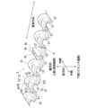
図3は、実施形態に係るエキスパンダ本体3の一部の斜視図である。図3に示すように、エキスパンダ本体3は、軸方向に変位する波状をなす周期要素が周方向に複数連なって構成されている。換言すると、エキスパンダ本体3は、オイルリング40の径方向視(径方向の外側または内側から視認したとき)において周方向に連続する波状に形成されている。具体的には、エキスパンダ本体3は、軸方向及び周方向に離間して周方向に交互に配置された複数の上片31及び下片32と、周方向において隣り合う上片31と下片32と連結する連結片33と、を含む。複数の上片31は、周方向に沿って間隔を空けて配列されている。複数の下片32は、オイルリング40がピストン20に組み付けられた際に(つまり使用状態において)複数の上片31よりも下側に位置するように、設けられている
。また、複数の下片32は、下片32の夫々が周方向において上片31の夫々と交互に配置されるように配列されている。上片31及び下片32は、軸方向と直交するように設けられており、軸方向において互いに離間している。連結片33は、周方向において隣り合う上片31と下片32の周方向における端部同士を連結している。また、図3に示すように、エキスパンダ本体3は、互いに対向することで合口G1を形成する一対の合口端部3a,3bを含む。なお、本発明に係るエキスパンダ本体の構造はこれに限定されるものではなく、軸方向に波状に形成されていればよい。
FIG. 3 is a perspective view of a part of the
図1に示すように、上片31は、上側ベース部310と上側耳部311と上側支持部312とを含む。上側ベース部310は、軸方向と直交するように径方向に延びている。上側耳部311は、径方向における上側ベース部310の内側に起立形成されており、上側ベース部310に対して上側に突出している。また、上側耳部311は、使用状態において上側セグメント1Uの内周面12に当接することで上側セグメント1Uを径方向の外側へ押圧する。上側支持部312は、径方向における上側ベース部310の外側に起立形成されており、上側ベース部310に対して上側に突出している。また、上側支持部312は、使用状態において上側セグメント1Uの下面14に当接することで上側セグメント1Uを支持する。また、上側耳部311の根元には貫通孔34が形成されている。なお、本発明に係る上片は上側支持部312を有さなくてもよい。
As shown in FIG. 1, the
図1に示すように、下片32は、下側ベース部320と下側耳部321と下側支持部322とを含む。下側ベース部320は、軸方向と直交するように径方向に延びている。下側耳部321は、径方向における下側ベース部320の内側に起立形成されており、下側ベース部320に対して下側に突出している。また、下側耳部321は、使用状態において下側セグメント1Lの内周面12に当接することで下側セグメント1Lを径方向の外側へ押圧する。下側支持部322は、径方向における下側ベース部320の外側に起立形成されており、下側ベース部320に対して下側に突出している。また、下側支持部322は、使用状態において下側セグメント1Lの上面13に当接することで下側セグメント1Lを支持する。また、下側耳部321の根元には貫通孔34が形成されている。なお、本発明に係る下片は下側支持部322を有さなくてもよい。
As shown in FIG. 1, the
ここで、図1の符号E1は連結片33における径方向外側の端部(外側端部)を示し、符号E2は連結片33における径方向内側の端部(内側端部)を示す。また、外側端部E1の軸方向における幅をb1とする。図1に示すように、本例のb1は、上側支持部312の下面と下側支持部322の上面との軸方向における距離と等しい。
In FIG. 1, E1 indicates the radially outer end (outer end) of the connecting
また、図1及び図3に示すように、連結片33の外側端部E1には、径方向外側(外周側)に開口した切り欠き37が形成されている。切り欠き37の内壁は、径方向内側へ凸状となった円弧状に形成されている。但し、本発明に係る切り欠きの形状は円弧状に限定されない。切り欠き37は、周方向に沿って配列するように複数の連結片33に設けられている。これにより、エキスパンダ本体3の外周面S1には、周方向に沿って延在し外周側に開口したエキスパンダ溝4が形成されている。エキスパンダ溝4は、複数の切り欠き37を含んで形成されており、図3に示すように、合口G1を跨いで延在している。実施形態に係るエキスパンダ溝4は、エキスパンダ本体3の全周に亘って形成されている。但し、本発明に係るエキスパンダ溝はこれに限定されない。エキスパンダ溝は、合口を跨ぐようにエキスパンダ本体の少なくとも一部に形成されていればよい。なお、本例ではエキスパンダ溝4が軸方向において連結片33の中央に形成されているが、エキスパンダ溝4の軸方向における位置は、上片31側または下片32側に寄っていてもよい。
As shown in Figs. 1 and 3, a
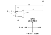
図4は、エキスパンダ本体3の外周径及び内周径を説明するための断面図である。図4の符号CA3は、エキスパンダ本体3の中心軸を示す。このとき、エキスパンダ本体3の
外周径、つまり、エキスパンダ本体3の最外周の曲率半径(エキスパンダ本体3の中心軸CA3から外周面S1までの距離)をR1とし、エキスパンダ本体3の内周径、つまり、エキスパンダ本体3の最内周の曲率半径(エキスパンダ本体3の中心軸CA3から内周面S2までの距離)をR2とする。即ち、R1はエキスパンダ本体3の外径であり、R2はエキスパンダ本体3の内径である。
Fig. 4 is a cross-sectional view for explaining the outer diameter and inner diameter of the
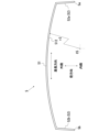
図5は、実施形態に係る線状部材5の上面図(軸方向の上側から視認した図)である。線状部材5は、線材を曲げ加工することで形成された線状の部材である。線状部材5の材質は特に限定されないが、スチール製や樹脂製のものを用いることができる。線状部材5の材質としては、SUS、SWP、樹脂等が例示される。図5に示すように、線状部材5は、嵌装部51と一対の屈曲部52,52とを含む。嵌装部51は、オイルリング40の周方向に沿って円弧状に延びている。図1に示すように、嵌装部51は、エキスパンダ本体3の外周面S1に形成されたエキスパンダ溝4の断面形状に対応するように、円形の断面形状を有している。但し、本発明はこれに限定されない。切り欠き37の断面形状と線状部材5の断面形状は必ずしも同一でなくてもよい。また、線状部材5の断面形状は円形でなくてもよい。また、嵌装部51の軸方向における幅w1(図1参照)は、連結片33の外側端部E1の軸方向における幅b1、即ち、軸方向における上側支持部312の下面と下側支持部322の上面との距離よりも小さい。
5 is a top view (viewed from above in the axial direction) of the
図5に示すように、嵌装部51の両端部には、夫々、屈曲部52が設けられている。以下、線状部材5が有する一対の屈曲部52,52を区別して説明する場合には、嵌装部51の一端部に接続された屈曲部52を第1屈曲部52aと称し、嵌装部51の他端部に接続された屈曲部52を第2屈曲部52bと称し、これらを区別しないで説明する場合には、単に屈曲部52と称する。屈曲部52は、嵌装部51の端部に接続されており、線状部材5が嵌装部51の端部から径方向内側に折れ曲がることで形成されている。本例の屈曲部52は、嵌装部51の端部から径方向内側へ真っ直ぐ延在している。屈曲部52の先端は、線状部材5の端部を構成する。具体的には、線状部材5の一端部5aは第1屈曲部52aに含まれ、他端部5bは第2屈曲部52bに含まれる。なお、本明細書では、線状部材の線長方向において、屈曲部が接続される嵌装部側を屈曲部の基端側とし、線状部材の端部側を屈曲部の先端側とする。
As shown in FIG. 5, a
ここで、図5の符号512は、線状部材5の嵌装部51の内周端部を示す。内周端部512は、嵌装部51の内周面の一部であって、嵌装部51において最も径方向内側に位置する部位である。また、符号C5は、嵌装部51がなす円弧の中心を示す。このとき、嵌装部51の内周端部512における線状部材5の曲率半径(嵌装部51の円弧の中心C5から内周端部512までの距離)をr2とする。
Here,
図6は、実施形態に係るスペーサエキスパンダ2の一部の斜視図である。図6では、一対の合口端部3a,3b同士を突き合わせた(当接させた)状態が図示されている。図6に示すように、スペーサエキスパンダ2では、線状部材5の嵌装部51が合口G1に跨るようにエキスパンダ本体3のエキスパンダ溝4に嵌装されている。嵌装部51とエキスパンダ溝4との嵌め合いは遊嵌状態となっている。
Figure 6 is a perspective view of a portion of the
このとき、本例に係るスペーサエキスパンダ2では、自由状態において、線状部材5の嵌装部51の内周端部512における円弧の曲率半径r2が一対の合口端部3a,3b同士を突き当てた状態のエキスパンダ本体3の最外周の曲率半径R1以下となるように、R1及びr2の寸法が設定されている。これにより、線状部材5がエキスパンダ溝4に嵌装された状態とすることができる。ここで、r2の寸法がR1の寸法未満の場合には、線状部材5がエキスパンダ溝4に嵌装されることで線状部材5が拡径されるため、線状部材5には縮径しようとする自己張力が生じる。そのため、線状部材5がエキスパンダ溝4に嵌
装されたスペーサエキスパンダ2では、線状部材5の内周端部512がエキスパンダ本体3を径方向の内側へ押圧した状態となる。これにより、線状部材5が合口G1に跨ってエキスパンダ溝4に嵌装された状態が維持される。
At this time, in the
図7は、実施形態に係るスペーサエキスパンダ2がリング溝30に装着された状態を示す上面図である。図7の符号G2は、周方向において隣り合う連結片33同士の間に形成された空間(以下、連結片間隙と称する)を示す。図7に示すように、線状部材5がエキスパンダ溝4に嵌装されたスペーサエキスパンダ2では、線状部材5の一対の屈曲部52,52が、連結片間隙G2を通ってエキスパンダ本体3の内周側に突出している。具体的には、第1屈曲部52aが合口端部3a側の連結片間隙G2を通り、第2屈曲部52bが合口端部3b側の連結片間隙G2を通っている。そして、スペーサエキスパンダ2がリング溝30に装着された状態では、一対の屈曲部52,52は、夫々の先端がオイル戻し孔30aに挿入されている。具体的には、リング溝30の底壁面303に形成された複数のオイル戻し孔30aのうち、一つのオイル戻し孔30aに第1屈曲部52aの端部5aが挿入されており、別のオイル戻し孔30aに第2屈曲部52bの端部5bが挿入されている。
Figure 7 is a top view showing the state in which the
スペーサエキスパンダ2では、屈曲部52の一部が連結片間隙G2を通ってスペーサエキスパンダ2の内周側に突出しているため、エキスパンダ本体3が線状部材5に対して周方向に回転しようとすると、屈曲部52と連結片33とが当接することとなる。そのため、エキスパンダ本体3と線状部材5との相対回転が抑制されている。そして、内周側に突出した屈曲部52の一部がオイル戻し孔30aに挿入されているため、線状部材5がピストン20に対して周方向に回転しようとすると、屈曲部52がオイル戻し孔30aの内壁に当接することとなる。そのため、線状部材5とピストン20との相対回転が抑制されている。これにより、スペーサエキスパンダ2がピストン20に対して周方向に回転することが抑制されている。なお、屈曲部52の先端部(つまり、線状部材5の端部5a,5b)のみをくの字状に折り曲げ、屈曲部52の折り曲げ部分がオイル戻し孔30aの内壁に当接するようにしてもよい。そうすることで、屈曲部52がオイル戻し孔30aの内壁を攻撃することを抑制できる。
In the
なお、セグメント1とエキスパンダ本体3のうち、少なくとも何れか一方の表面には、樹脂被膜、窒化処理被膜、Ni-Pめっき処理被膜、クロムめっき処理被膜、PVD処理被
膜、及びDLC処理被膜のうち少なくとも何れか1つの層を含む被膜が形成されてもよい。なお、「樹脂被膜」とは、樹脂材料により形成された被膜のことを指す。また、「窒化処理被膜」とは、窒化処理により金属表面に窒素を浸透させることで形成される被膜のことを指す。また、「Ni-Pめっき処理被膜」とは、無電解Ni-Pめっきにより形成された被膜のことを指す。また、「クロムめっき処理被膜」とは、クロムめっきにより形成された被膜のことを指す。クロムめっきは工業用クロムめっきとも呼ばれる。また、「PVD(physical vapor deposition)処理被膜」とは、PVD法により形成された被膜のことを
指す。また、「DLC(Diamond Like Carbon)処理被膜」とは、主として炭素の同素体
により構成される非晶質の硬質炭素被膜のことを指す。このような被膜を形成することで、セグメント1又はエキスパンダ本体3の耐摩耗性を高めることができる。
At least one of the
[オイルリングのピストンへの組付]
次に、実施形態に係るオイルリング40のピストン20への組付方法について説明する。オイルリング40をピストン20に組み付けるには、まず、エキスパンダ本体3をリング溝30に装着する。次に、嵌装部51をエキスパンダ溝4に嵌め込むと共に屈曲部52を連結片間隙G2に差し込むことで、線状部材5をエキスパンダ本体3に嵌装させる。線状部材5をエキスパンダ本体3Hに嵌装させることで、一対の合口端部3a,3b同士の重なりが嵌装部51によって防止される。その後、スペーサエキスパンダ2へ一対のセグ
メント1,1を装着する。上述のように、スペーサエキスパンダ2では、線状部材5が合口G1に跨ってエキスパンダ溝4に嵌装された状態が維持されている。そのため、スペーサエキスパンダ2へ一対のセグメント1,1を装着する際において、エキスパンダ本体3は一対の合口端部3a,3b同士が対向した姿勢に維持され、一対の合口端部3a,3b同士が重なることが防止される。これに加え、エキスパンダ本体3の内周側に突出した線状部材5の屈曲部52がオイル戻し孔30aに挿入されることで、内燃機関100の運転時におけるスペーサエキスパンダ2の周方向の回転が抑制される。
[Installation of oil ring to piston]
Next, a method of assembling the
[作用・効果]
以上のように、実施形態に係るスペーサエキスパンダ2は、オイルリング40の周方向に沿って環状に形成され、オイルリング40の径方向視において周方向に連続する波状に形成されたエキスパンダ本体3と、合口G1を跨いでオイルリング40の周方向に沿って延在するようにエキスパンダ本体3に形成されたエキスパンダ溝4と、エキスパンダ本体3に装着される線状部材5と、を備える。また、線状部材5は、オイルリング40の周方向に沿って円弧状に形成された嵌装部51と、嵌装部51の端部からオイルリング40の径方向内側に折れ曲がった屈曲部52を含む。そして、嵌装部51が合口G1に跨るようにエキスパンダ溝4に嵌装され、屈曲部52の一部がエキスパンダ本体3の内周側に突出してリング溝30の内壁に形成されたオイル戻し孔30aに挿入される。
[Action and Effects]
As described above, the
実施形態に係るスペーサエキスパンダ2によると、嵌装部51がエキスパンダ本体3の合口G1に跨るようにエキスパンダ溝4に嵌装されることで、スペーサエキスパンダ2へ一対のセグメント1,1を装着する際において、一対の合口端部3a,3b同士が対向した姿勢が維持され、一対の合口端部3a,3b同士が径方向や軸方向において重なることを防止できる。更に、スペーサエキスパンダ2によると、屈曲部52の一部がエキスパンダ本体3の内周側に突出してリング溝30のオイル戻し孔30aに挿入されることで、オイルリング40がピストン20に対して周方向に回転することを抑制できる。
According to the
このようなスペーサエキスパンダ2によれば、エキスパンダ本体3の一対の合口端部3a,3b同士の重なりを防止することで、オイルリング40のピストン20への組み付け作業においてセグメント1が組み付け難くなることや、ピストン20に組み付けられたオイルリング40がシール機能を十分に発揮できなくなることを防止できる。また、オイルリング40の周方向の回転を抑制することで、水平対向エンジン等のシリンダが水平または水平に近い状態で傾斜した内燃機関において、オイル上りによるオイル消費の悪化や燃焼阻害や、オイル燃焼によるスラッジ増加に伴うリング固着といった不具合を防止することができる。また、セグメントの合口端部を折り曲げることなくオイルリング40の回転を抑制できるため、セグメントのスタック性や曲げ加工部の折損の不具合が生じ難いという利点もある。このように、スペーサエキスパンダ2によると、エキスパンダ本体3の合口端部3a,3b同士の重なり防止とオイルリング40の回転抑制とを、線状部材5を利用した比較的簡単な構成で実現可能とする。
According to such a
更に、軸方向波状スペーサエキスパンダは、軸方向の幅や径方向の厚さが狭いため、線状部材を挿入するための孔を設けるのは困難であるが、実施形態に係るスペーサエキスパンダ2は、溝を設けることで線状部材5を嵌装する構造を採用している。これにより、軸方向波状スペーサエキスパンダでありながらも、一対の合口端部同士の重なりを防止することが可能となっている。更に、実施形態に係るスペーサエキスパンダ2は、エキスパンダ本体3に形成され外部に開口したエキスパンダ溝4に線状部材5を嵌装する構成を採用している。これにより、合口端部同士をピンなどで固定する技術とは異なり、スペーサエキスパンダ2をピストン20に対して容易に着脱することできる。そのため、セグメント1とスペーサエキスパンダ2とを含めたオイルリング40の交換が容易となる。これにより、オイルリング40を補用品(補修用部品)として利用することができる。
Furthermore, since the axial wavy spacer expander has a narrow axial width and a narrow radial thickness, it is difficult to provide a hole for inserting a linear member, but the
更に、実施形態に係るスペーサエキスパンダ2のエキスパンダ溝4は、オイルリング40の周方向に沿って配列するように複数の連結片33の外側端部E1に設けられた切り欠き37によってエキスパンダ本体3の外周面S1に形成されている。そして、軸方向における線状部材5の嵌装部51の幅w1は、軸方向における連結片33の外側端部E1の幅b1(本例では、軸方向における上側支持部312の下面と下側支持部322の上面との距離)よりも小さい。これによると、嵌装部51の軸方向における幅w1を連結片33の外側端部E1の軸方向における幅b1よりも小さくすることで、嵌装部51を一対のセグメント1,1の間に嵌装させることができる。
Furthermore, the
更に、実施形態に係るスペーサエキスパンダ2では、自由状態における線状部材5の嵌装部51の内周端部512における円弧の曲率半径r2が、自由状態における一対の合口端部3a,3b同士を突き当てた状態のエキスパンダ本体3の最外周の曲率半径R1以下となっている。これにより、スペーサエキスパンダ2は、線状部材5が合口G1に跨ってエキスパンダ溝4に嵌装された状態を維持することができる。なお、自由状態における線状部材5の曲率半径r2は、自由状態において一対の合口端部3a,3b同士を突き当てた状態のエキスパンダ本体3の曲率半径R1に対して0~-10%の範囲内とすることが好ましく、0~-5%の範囲内とすることがより好ましい。これにより、線状部材5がエキスパンダ溝4から外れ難くすることができる。但し、本発明はこれに限定されない。
Furthermore, in the
なお、本例では、屈曲部52が嵌装部51の両端部に設けられているが、本発明では、屈曲部は、嵌装部の両端部のうち、少なくとも一方に設けられていればよい。例えば、線状部材5において、嵌装部51の一端部のみに屈曲部52が設けられていてもよい。
In this example, the
なお、本例では、屈曲部52の一部がリング溝30の内壁に形成されたオイル戻し孔30aに挿入される構成となっているが、本発明において屈曲部の一部が挿入される被挿入部は、オイル戻し孔に限定されない。被挿入部は、例えば、ピストンに設けられた「切欠き溝」や「留め孔」であってもよく、本発明は、これらに屈曲部の一部を挿入する構成としてもよい。ここで、「切欠き溝」とは、リング溝に設けられた孔であり、ピストンの内周側に貫通していない孔のことをいう。また、「留め孔」とは、線状部材の先端を挿入する目的でリング溝の内壁に設けられた孔のことをいう。また、被挿入部が形成される箇所は、リング溝の底壁面に限定されない。
In this example, a portion of the
[変形例]
以下、実施形態の変形例について説明する。以下の説明では、上述のオイルリング40との相違点を中心に説明し、同様の構成については同一の符号を付すことにより詳細な説明は割愛する。
[Modification]
Modifications of the embodiment will be described below. In the following description, differences from the above-described
[変形例1]
図8は、変形例1に係る線状部材5Aの上面図である。図9は、変形例1に係るスペーサエキスパンダ2Aがリング溝30に装着された状態を示す上面図である。図8に示すように、変形例1に係る線状部材5Aは、屈曲部の形状が図5等で示した線状部材5と相違する。
[Modification 1]
Fig. 8 is a top view of a
図8に示すように、線状部材5Aは、嵌装部51と、嵌装部51の一端部に設けられた屈曲部53と、嵌装部51の他端部に設けられた係止部54と、を含む。屈曲部53及び係止部54は、嵌装部51の端部に接続されており、線状部材5Aが嵌装部51の端部から径方向内側に折れ曲がることで形成されている。屈曲部53は、嵌装部51の端部から折れ曲がって径方向内側へ延びる延在部531と、延在部531の先端から折れ曲がって周方向外側(嵌装部51とは反対の方向)へ延びる係合部532と、係合部532の先端
から折れ曲がって径方向内側へ延びる挿入部533と、を含む。挿入部533は、線状部材5Aの端部5aを含む。また、係止部54は、嵌装部51の端部から折れ曲がって径方向内側へ延びる延在部541と、延在部541の先端から折れ曲がって周方向外側へ延びる係合部542と、を含む。係合部542は、線状部材5Aの端部5bを含む。
As shown in Fig. 8, the
図9に示すように、スペーサエキスパンダ2Aがリング溝30に装着された状態では、屈曲部53の延在部531が連結片間隙G2を通ってエキスパンダ本体3の内周側へ延び、係合部532が連結片33の内側端部E2に係合し、挿入部533がエキスパンダ本体3の内周側に突出してオイル戻し孔30aに挿入されている。また、係止部54の延在部541が連結片間隙G2を通ってエキスパンダ本体3の内周側へ延び、係合部542が連結片33の内側端部E2に係合している。
As shown in FIG. 9, when the
スペーサエキスパンダ2Aでは、屈曲部53の延在部531と係止部54の延在部541とが連結片間隙G2を通っているため、延在部531と延在部541とが連結片33に当接することで、エキスパンダ本体3と線状部材5Aとの相対回転が抑制されている。そして、挿入部533がオイル戻し孔30aに挿入されているため、挿入部533がオイル戻し孔30aの内壁に当接することで、線状部材5Aとピストン20との相対回転が抑制されている。これにより、スペーサエキスパンダ2Aがピストン20に対して周方向に回転することが抑制されている。更に、屈曲部53の係合部532と係止部54の係合部542とが連結片33の内側端部E2に係合することで、線状部材5Aがエキスパンダ本体3に対して径方向外側に移動することが抑制されている。これにより、線状部材5Aがエキスパンダ本体3に係止され、線状部材5Aがエキスパンダ本体3から外れることが防止されている。
In the
線状部材5Aをエキスパンダ本体3に嵌装させるには、線状部材5Aの弾性力に抗して屈曲部53及び係止部54を周方向内側(嵌装部51側)に縮めた状態とし、嵌装部51をエキスパンダ溝4に嵌め込むと共に屈曲部53及び係止部54を連結片間隙G2に差し込み、係合部532及び係合部542を連結片33の内側端部E2に係合させる。線状部材5Aがエキスパンダ本体3に嵌装した状態では、線状部材5Aの弾性によって周方向外側に張り出そうとする復元力が屈曲部53及び係止部54に生じるため、延在部531及び延在部541が連結片33に対して押し付けられた状態(突っ張った状態)となる。そのため、係合部532及び係合部542が連結片33に係合した状態が維持される。
To fit the
変形例1に係るスペーサエキスパンダ2Aによると、上述のスペーサエキスパンダ2と同様に、線状部材5Aを利用した比較的簡単な構成で、エキスパンダ本体3の合口端部3a,3b同士の重なり防止とオイルリング40の回転抑制とを実現できる。更に、線状部材5Aがエキスパンダ本体3から外れることを防止できる。なお、本例では、嵌装部51の一端部のみに屈曲部53が設けられているが、嵌装部51の両端部に屈曲部53が設けられてもよい。つまり、係止部54に代えて屈曲部53が設けられてもよい。
The
[変形例2]
図10は、変形例2に係る線状部材5Bの上面図である。図11は、変形例2に係るスペーサエキスパンダ2Bがリング溝30に装着された状態を示す上面図である。図10に示すように、変形例2に係る線状部材5Bは、屈曲部の形状が図5等で示した線状部材5と相違している。
[Modification 2]
Fig. 10 is a top view of a
図10に示すように、線状部材5Bは、嵌装部51と、嵌装部51の両端部に設けられた一対の屈曲部55,55と、を含む。以下、線状部材5Bが有する一対の屈曲部55,55を区別して説明する場合には、嵌装部51の一端部に接続された屈曲部55を第1屈曲部55aと称し、嵌装部51の他端部に接続された屈曲部55を第2屈曲部55bと称
し、これらを区別しないで説明する場合には、単に屈曲部55と称する。屈曲部55は、嵌装部51の端部に接続されており、線状部材5Bが嵌装部51の端部から径方向内側に折れ曲がることで形成されている。第1屈曲部55aは線状部材5Bの端部5aを含み、第2屈曲部55bは線状部材5Bの端部5bを含む。屈曲部55は、嵌装部51の端部から折れ曲がって径方向内側へ延びる第1延在部551と、第1延在部551の先端から折り返されて径方向内側へ延びる第2延在部552と、を含む。図10において、第1延在部551と第2延在部552との折り曲げ部(接続部分)を符号553で示す。
As shown in Fig. 10, the
図11に示すように、スペーサエキスパンダ2Bがリング溝30に装着された状態では、屈曲部55の第1延在部551が連結片間隙G2を通ってエキスパンダ本体3の内周側へ延び、第1延在部551の先端から折り返された第2延在部552が当該連結片間隙G2とは別の(本例では隣の)連結片間隙G2に挿入されている。そして、第1延在部551と第2延在部552との折り曲げ部553がエキスパンダ本体3の内周側に突出してオイル戻し孔30aに挿入されている。
As shown in FIG. 11, when the
スペーサエキスパンダ2Bでは、屈曲部55の第1延在部551が連結片間隙G2を通っているため、第1延在部551が連結片33に当接することで、エキスパンダ本体3と線状部材5Bとの相対回転が抑制されている。そして、折り曲げ部553がオイル戻し孔30aに挿入されているため、屈曲部52がオイル戻し孔30aの内壁に当接することで、線状部材5Aとピストン20との相対回転が抑制されている。これにより、スペーサエキスパンダ2Aがピストン20に対して周方向に回転することが抑制されている。更に、第1延在部551の先端から折り返された第2延在部552が、第1延在部551が通る連結片間隙G2とは別の連結片間隙G2を通っているため、線状部材5Bがエキスパンダ本体3に対して径方向外側に移動しようとすると、屈曲部55と連結片33とが当接することとなる。そのため、線状部材5Bがエキスパンダ本体3に対して径方向外側に移動することが抑制されている。これにより、線状部材5Bがエキスパンダ本体3に係止され、線状部材5Bがエキスパンダ本体3から外れることが防止されている。
In the
変形例2に係るスペーサエキスパンダ2Bによると、上述のスペーサエキスパンダ2,2Aと同様に、比較的簡単な構成で、エキスパンダ本体3の合口端部3a,3b同士の重なり防止とオイルリング40の回転抑制とを実現できる。更に、線状部材5Bがエキスパンダ本体3から外れることを防止できる。なお、本例では、嵌装部51の両端部に屈曲部55が設けられていたが、嵌装部51の一端部のみに屈曲部55が設けられてもよい。また、本例では、屈曲部55の第2延在部552は、第1延在部551が通る連結片間隙G2の隣の連結片間隙G2を通っているが、第2延在部552が通るのは当該隣の連結片間隙G2でなくてもよく、例えば、更に隣の連結片間隙G2であってもよい。
The
[変形例3]
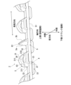
図12は、変形例3に係るセグメント1の内周面12を示す図である。図12では、変形例3に係るセグメント1を径方向内側から視認した状態が図示されている。図12に示すように、変形例3に係るセグメント1の内周面には、符号15で示す回転抑制部が複数形成されている。図13は、回転抑制部15の断面図である。図13では、オイルリング40の軸方向に直交する断面が図示されている。
[Modification 3]
Fig. 12 is a diagram showing the inner
図12に示すように、回転抑制部15は、溝部151と一対の突出部152,152と、を含む。溝部151は、図13に示すように内周面12において凹んで形成されており、図12に示すようにオイルリングの軸方向に対して傾斜して延びている。また、一対の突出部152,152は、図13に示すように内周面12において溝部151の両側に突出して形成されており、図12に示すように溝部151に沿って延びている。つまり、土手状に連続する一対の突出部152,152が、溝部151を挟んで溝部151に沿って
延びている。
As shown in Fig. 12, the
また、図12に示すように、変形例3に係るセグメント1では、セグメント1の内周面12に沿って時計回りに進むに従って上側(燃焼室側)に向かうように傾斜する回転抑制部15と、下側(クランク室側)に向かうように傾斜する回転抑制部15とが、周方向において交互に形成されている。但し、回転抑制部15は、上側に向かうように傾斜するもののみとしてもよいし、下側に向かうように傾斜するもののみとしてもよい。また、複数の回転抑制部15は、溝部151の傾斜角度が異なっていてもよい。
As shown in FIG. 12, in the
回転抑制部15は、レーザ加工によって形成することができる。具体的には、セグメント1の線材において内周面12となる面にレーザ光を照射し、溝加工を施すことで、内周面12に回転抑制部15が形成される。線材におけるレーザ光の照射部位が溶融して溝部151が形成され、溝部151の両側に、溶融した金属が冷えて固まることにより凸状のドロスが形成される。この凸状のドロスが、一対の突出部152,152となる。
The
以上のように、変形例3に係るセグメント1は、オイルリング40においてスペーサエキスパンダ2の上側耳部311又は下側耳部321に当接する内周面12に、溝部151と一対の突出部152,152とを含む回転抑制部15が複数形成されている。これによると、一対の突出部152,152がスペーサエキスパンダ2の耳部に当接することで、セグメント1がスペーサエキスパンダ2に対して周方向に回転すること(単独回転)に対しての抵抗となる。これにより、セグメント1の単独回転が抑制される。そのため、変形例3に係るセグメント1を用いたオイルリング40では、線状部材5によってスペーサエキスパンダ2の回転を抑制し、更に、回転抑制部15によってセグメント1の単独回転を抑制できる。セグメント1の単独回転を抑制することで、上下のセグメント1の合口が軸方向に重なることを抑制できる。なお、回転抑制部15は、オイルリング40に設けられる一対のセグメント1,1のうち、少なくとも一方の内周面に形成されていればよい。但し、一対のセグメント1,1の両方の内周面12に回転抑制部15を形成することが、より好ましい。
As described above, in the
なお、図12に示すように、溝部151のオイルリング40の軸方向に対する傾斜角度(即ち、回転抑制部15の傾斜角度)をθ1とすると、セグメント1の単独回転抑制の観点では、θ1を90°以外とすることが好ましく、45°以下とすることが更に好ましい。但し、本発明はこれに限定されない。また、セグメント1の単独回転を抑制するために、回転抑制部15に代えて、または、回転抑制部15と共に、ディンプルを内周面12に形成してもよい。また、内周面12に粗化処理を施してもよいし、樹脂被膜や軟質金属被膜を設けてもよい。
As shown in FIG. 12, if the inclination angle of the
<その他>
以上、本発明の好適な実施形態について説明したが、上述した種々の形態は、可能な限り組み合わせることができる。
<Other>
Although the preferred embodiments of the present invention have been described above, the above-mentioned various aspects can be combined to the extent possible.
100:内燃機関
10:シリンダ
20:ピストン
30:リング溝
40:オイルリング
1:セグメント
2,2A,2B:スペーサエキスパンダ
3:エキスパンダ本体
4:エキスパンダ溝
5,5A,5B:線状部材
100: Internal combustion engine 10: Cylinder 20: Piston 30: Ring groove 40: Oil ring 1:
Claims (6)
前記オイルリングの周方向に沿って環状に形成され、前記一対のセグメントを前記オイルリングの径方向における外側へ付勢するエキスパンダ本体であって、互いに対向することで合口を形成する一対の合口端部を含み、前記オイルリングの径方向視において周方向に連続する波状に形成されたエキスパンダ本体と、
前記合口を跨いで前記オイルリングの周方向に沿って延在するように前記エキスパンダ本体の外周面に形成されたエキスパンダ溝と、
前記エキスパンダ本体に装着される線状部材と、を備え、
前記線状部材は、前記オイルリングの周方向に沿って円弧状に形成された嵌装部と、前記嵌装部の両端部のうち少なくとも一方に設けられ、前記嵌装部の端部から前記オイルリングの径方向内側に折れ曲がった屈曲部と、を含み、
前記嵌装部は、前記合口に跨るように前記エキスパンダ溝に嵌装され、
前記屈曲部の一部は、前記エキスパンダ本体の内周側に突出すると共に前記リング溝の内壁に形成された被挿入部に挿入される、
スペーサエキスパンダ。 A spacer expander is provided between a pair of segments spaced apart in an axial direction of an oil ring that is fitted in a ring groove formed in a piston of an internal combustion engine, the spacer expander comprising:
an expander body that is formed in an annular shape along the circumferential direction of the oil ring and biases the pair of segments outward in the radial direction of the oil ring, the expander body including a pair of joint ends that face each other to form a joint, and that is formed in a wavy shape that is continuous in the circumferential direction when viewed in the radial direction of the oil ring;
an expander groove formed on an outer peripheral surface of the expander body so as to extend along a circumferential direction of the oil ring across the joint;
A linear member attached to the expander body,
the linear member includes a fitted portion formed in an arc shape along a circumferential direction of the oil ring, and a bent portion provided on at least one of both end portions of the fitted portion and bent from the end portion of the fitted portion toward a radially inward direction of the oil ring,
The fitting portion is fitted into the expander groove so as to span the joint,
A part of the bent portion protrudes toward the inner periphery of the expander body and is inserted into an insertion portion formed on an inner wall of the ring groove.
Spacer expander.
前記オイルリングの周方向に沿って間隔を空けて配列された複数の上片と、
前記オイルリングが前記ピストンに組み付けられた際に前記オイルリングの軸方向において前記複数の上片よりも前記内燃機関におけるクランク室側に位置するように設けられた複数の下片であって、前記下片の夫々が前記オイルリングの周方向において前記上片の夫々と交互に配置されるように配列された、複数の下片と、
前記オイルリングの周方向において隣り合う前記上片と前記下片とを連結する複数の連結片と、を含み、
前記上片は、上側ベース部と、前記オイルリングの径方向における前記上側ベース部の内側に起立形成され、前記一対のセグメントのうち前記内燃機関における燃焼室側に設けられた上側セグメントの内周面に当接することで当該上側セグメントを前記オイルリングの径方向の外側へ押圧する上側耳部と、を含み、
前記下片は、下側ベース部と、前記オイルリングの径方向における前記下側ベース部の内側に起立形成され、前記一対のセグメントのうち前記内燃機関における前記クランク室側に設けられた下側セグメントの内周面に当接することで当該下側セグメントを前記オイルリングの径方向の外側へ押圧する下側耳部と、を含む、
請求項1に記載のスペーサエキスパンダ。 The expander body includes:
A plurality of upper pieces arranged at intervals along a circumferential direction of the oil ring;
a plurality of lower pieces provided so as to be located closer to a crank chamber in the internal combustion engine than the plurality of upper pieces in an axial direction of the oil ring when the oil ring is assembled to the piston, the lower pieces being arranged so as to be alternately disposed with the respective upper pieces in a circumferential direction of the oil ring;
a plurality of connecting pieces connecting the upper piece and the lower piece adjacent to each other in a circumferential direction of the oil ring,
the upper piece includes an upper base portion, and an upper ear portion that is formed to rise from inside the upper base portion in a radial direction of the oil ring and abuts against an inner peripheral surface of an upper segment of the pair of segments that is provided on a combustion chamber side of the internal combustion engine, thereby pressing the upper segment outward in the radial direction of the oil ring,
the lower piece includes a lower base portion, and a lower ear portion that is formed to rise from the inside of the lower base portion in the radial direction of the oil ring and abuts against an inner peripheral surface of a lower segment of the pair of segments that is provided on the crank chamber side of the internal combustion engine, thereby pressing the lower segment outward in the radial direction of the oil ring.
2. The spacer expander of claim 1.
請求項2に記載のスペーサエキスパンダ。 The bent portion includes an extension portion that bends from an end of the fitting portion and extends toward the inner circumferential side of the expander body through a connecting piece gap between the connecting pieces adjacent in the circumferential direction, an engagement portion that bends from a tip of the extension portion and engages with an inner end portion that is an end portion of the connecting piece on the radially inner side of the oil ring, and an insertion portion that bends from a tip of the engagement portion and is inserted into the inserted portion.
3. The spacer expander of claim 2.
前記第1延在部と前記第2延在部との折り曲げ部が前記被挿入部に挿入される、
請求項2に記載のスペーサエキスパンダ。 the bent portion includes a first extending portion that is bent from an end of the fitting portion and extends through a connecting piece gap between adjacent connecting pieces in the circumferential direction toward the inner circumferential side of the expander body, and a second extending portion that is folded back from a tip of the first extending portion and inserted into a connecting piece gap other than the connecting piece gap through which the first extending portion passes,
A bent portion of the first extension portion and the second extension portion is inserted into the inserted portion.
3. The spacer expander of claim 2.
請求項1から4の何れか一項に記載のスペーサエキスパンダ。 At least one of the pair of segments has an inner peripheral surface formed with a plurality of rotation suppressing portions, the rotation suppressing portions including a groove portion extending at an angle with respect to the axial direction of the oil ring and a pair of bank-shaped protrusions extending along the groove portion on either side of the groove portion.
A spacer expander according to any one of claims 1 to 4.
前記オイルリングの軸方向に離間して設けられる一対のセグメントと、前記一対のセグメントの間に設けられるスペーサエキスパンダと、を備え、
前記スペーサエキスパンダは、
前記オイルリングの周方向に沿って環状に形成され、前記一対のセグメントを前記オイルリングの径方向における外側へ付勢するエキスパンダ本体であって、互いに対向することで合口を形成する一対の合口端部を含み、前記オイルリングの径方向視において周方向に連続する波状に形成されたエキスパンダ本体と、
前記合口を跨いで前記オイルリングの周方向に沿って延在するように前記エキスパンダ本体の外周面に形成されたエキスパンダ溝と、
前記エキスパンダ本体に装着される線状部材と、を備え、
前記線状部材は、前記オイルリングの周方向に沿って円弧状に形成された嵌装部と、前記嵌装部の両端部のうち少なくとも一方に設けられ、前記嵌装部の端部から前記オイルリングの径方向内側に折れ曲がった屈曲部と、を含み、
前記嵌装部は、前記合口に跨るように前記エキスパンダ溝に嵌装され、
前記屈曲部の一部は、前記エキスパンダ本体の内周側に突出すると共に前記リング溝の内壁に形成された被挿入部に挿入される、
オイルリング。 An oil ring that is fitted to a ring groove formed in a piston of an internal combustion engine,
a pair of segments spaced apart in an axial direction of the oil ring; and a spacer expander provided between the pair of segments,
The spacer expander includes:
an expander body that is formed in an annular shape along the circumferential direction of the oil ring and biases the pair of segments outward in the radial direction of the oil ring, the expander body including a pair of joint ends that face each other to form a joint, and that is formed in a wavy shape that is continuous in the circumferential direction when viewed in the radial direction of the oil ring;
an expander groove formed on an outer peripheral surface of the expander body so as to extend along a circumferential direction of the oil ring across the joint;
A linear member attached to the expander body,
the linear member includes a fitted portion formed in an arc shape along a circumferential direction of the oil ring, and a bent portion provided on at least one of both end portions of the fitted portion and bent from the end portion of the fitted portion toward a radially inward direction of the oil ring,
The fitting portion is fitted into the expander groove so as to span the joint,
A part of the bent portion protrudes toward the inner periphery of the expander body and is inserted into an insertion portion formed on an inner wall of the ring groove.
Oil ring.
Priority Applications (1)
| Application Number | Priority Date | Filing Date | Title |
|---|---|---|---|
| JP2021159344A JP7578570B2 (en) | 2021-09-29 | 2021-09-29 | Spacer expander and oil ring |
Applications Claiming Priority (1)
| Application Number | Priority Date | Filing Date | Title |
|---|---|---|---|
| JP2021159344A JP7578570B2 (en) | 2021-09-29 | 2021-09-29 | Spacer expander and oil ring |
Publications (2)
| Publication Number | Publication Date |
|---|---|
| JP2023049550A JP2023049550A (en) | 2023-04-10 |
| JP7578570B2 true JP7578570B2 (en) | 2024-11-06 |
Family
ID=85801938
Family Applications (1)
| Application Number | Title | Priority Date | Filing Date |
|---|---|---|---|
| JP2021159344A Active JP7578570B2 (en) | 2021-09-29 | 2021-09-29 | Spacer expander and oil ring |
Country Status (1)
| Country | Link |
|---|---|
| JP (1) | JP7578570B2 (en) |
Citations (2)
| Publication number | Priority date | Publication date | Assignee | Title |
|---|---|---|---|---|
| DE19942698A1 (en) | 1998-09-08 | 2000-03-09 | Dana Corp | Seal assembly especially for vehicle exhaust pipes has primary sealing element with integral fastening clip fixed at shaped first end on primary element and engaging down by integral locking tongue into slit on first flange of pipe |
| WO2019064525A1 (en) | 2017-09-29 | 2019-04-04 | Tpr株式会社 | Segment, combined oil ring, and segment manufacturing method |
-
2021
- 2021-09-29 JP JP2021159344A patent/JP7578570B2/en active Active
Patent Citations (2)
| Publication number | Priority date | Publication date | Assignee | Title |
|---|---|---|---|---|
| DE19942698A1 (en) | 1998-09-08 | 2000-03-09 | Dana Corp | Seal assembly especially for vehicle exhaust pipes has primary sealing element with integral fastening clip fixed at shaped first end on primary element and engaging down by integral locking tongue into slit on first flange of pipe |
| WO2019064525A1 (en) | 2017-09-29 | 2019-04-04 | Tpr株式会社 | Segment, combined oil ring, and segment manufacturing method |
Also Published As
| Publication number | Publication date |
|---|---|
| JP2023049550A (en) | 2023-04-10 |
Similar Documents
| Publication | Publication Date | Title |
|---|---|---|
| CN107407412B (en) | Side rail | |
| JP4633639B2 (en) | 3-piece oil ring and combination of 3-piece oil ring and piston | |
| EP1431630B1 (en) | Combined oil ring | |
| JP7254836B2 (en) | Combined oil ring | |
| US20100119181A1 (en) | Sliding bearing for internal combustion engine and sliding bearing device | |
| JP7578570B2 (en) | Spacer expander and oil ring | |
| US10197160B2 (en) | Oil ring | |
| WO2023127607A1 (en) | Piston ring and piston ring set | |
| JP7631508B2 (en) | Spacer expander and oil ring | |
| JP2020041573A (en) | Piston ring and method of manufacturing piston ring | |
| JP7608309B2 (en) | Piston and piston ring combination structure | |
| JPH11200989A (en) | Fuel injection pump | |
| JP7529709B2 (en) | Oil Ring | |
| JP7529635B2 (en) | Upper segment and oil ring | |
| JPH08303298A (en) | Combination ring and seal structure equipped with it | |
| JPH08303590A (en) | Seal structure | |
| WO2025204990A1 (en) | Compression ring, compression ring combination, and ring body | |
| JP2023062620A (en) | piston structure | |
| JP6438679B2 (en) | Oil ring | |
| KR100444863B1 (en) | Piston ring | |
| WO2024202281A1 (en) | Oil ring | |
| JP2025115107A (en) | Piston rings for internal combustion engines | |
| JP2018141485A (en) | Plain bearing | |
| JP7053282B2 (en) | Oil ring | |
| JP2008039055A (en) | Roller support bearing device |
Legal Events
| Date | Code | Title | Description |
|---|---|---|---|
| A621 | Written request for application examination |
Free format text: JAPANESE INTERMEDIATE CODE: A621 Effective date: 20240418 |
|
| A977 | Report on retrieval |
Free format text: JAPANESE INTERMEDIATE CODE: A971007 Effective date: 20240912 |
|
| TRDD | Decision of grant or rejection written | ||
| A01 | Written decision to grant a patent or to grant a registration (utility model) |
Free format text: JAPANESE INTERMEDIATE CODE: A01 Effective date: 20240924 |
|
| A61 | First payment of annual fees (during grant procedure) |
Free format text: JAPANESE INTERMEDIATE CODE: A61 Effective date: 20241024 |
|
| R150 | Certificate of patent or registration of utility model |
Ref document number: 7578570 Country of ref document: JP Free format text: JAPANESE INTERMEDIATE CODE: R150 |