以下に、本願発明を具体化した実施形態を、普通型コンバインに適用した図面(図1~
図26)に基づいて説明する。まず、図1~図3を参照しながら、コンバインの概略構造
について説明する。なお、以下の説明では、走行機体1の前進方向に向かって左側を単に
左側と称し、同じく前進方向に向かって右側を単に右側と称する。
The following is a detailed description of an embodiment of the present invention applied to a normal type combine harvester, with reference to the drawings (FIGS. 1 to 4).
The following description will be made based on the drawings (FIG. 26). First, the general structure of the combine will be described with reference to FIGS. 1 to 3. In the following description, the left side facing the forward direction of the traveling body 1 will be simply referred to as the left side, and the right side facing the forward direction will be simply referred to as the right side.
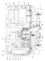
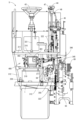
図1~図3に示す如く、実施形態における普通型コンバインは、走行部としてのゴムク
ローラ製の左右一対の履帯2にて支持された走行機体1を備える。走行機体1の前部には
、稲(又は麦又は大豆又はトウモロコシ)等の未刈り穀稈を刈取りながら取込む刈取部3
が単動式の昇降用油圧シリンダ4にて昇降調節可能に装着されている。
As shown in Figures 1 to 3, the conventional combine harvester in the embodiment includes a traveling body 1 supported by a pair of left and right tracks 2 made of rubber crawlers as a traveling part. At the front of the traveling body 1, there is a reaping part 3 that harvests and collects unharvested stalks such as rice (or wheat, soybeans, or corn).
is mounted so that its elevation can be adjusted by a single-acting lifting hydraulic cylinder 4.
走行機体1の左側には、刈取部3から供給された刈取穀稈を脱穀処理するための脱穀部
9を搭載する。脱穀部9の下部には、揺動選別及び風選別を行うための穀粒選別機構10
を配置する。走行機体1の前部右側には、オペレータが搭乗する操縦部としての運転台5
を搭載する。動力源としてのエンジン7を、運転台5(運転座席42の下方)に配置する
。運転台5の後方(走行機体1の右側)には、脱穀部9から穀粒を取出すグレンタンク6
と、トラック荷台(またはコンテナなど)に向けてグレンタンク6内の穀粒を排出する穀
粒排出コンベヤ8を配置する。穀粒排出コンベヤ8を機外側方に傾倒させて、グレンタン
ク6内の穀粒を穀粒排出コンベヤ8にて搬出するように構成している。
A threshing unit 9 for threshing the harvested stalks supplied from the harvesting unit 3 is mounted on the left side of the traveling machine body 1. A grain sorting mechanism 10 for performing rocking sorting and wind sorting is mounted on the lower part of the threshing unit 9.
On the right front part of the traveling body 1, a driver's seat 5 is arranged as a control section where an operator sits.
The engine 7 as a power source is disposed in the cab 5 (below the cab 42). A grain tank 6 for removing grains from the threshing section 9 is disposed behind the cab 5 (to the right of the traveling machine body 1).
A grain discharge conveyor 8 is disposed to discharge the grains in the grain tank 6 toward the truck bed (or a container, etc.). The grain discharge conveyor 8 is tilted toward the outside of the machine so that the grains in the grain tank 6 are carried out by the grain discharge conveyor 8.
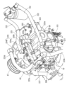
刈取部3は、脱穀部9前部の扱口9aに連通したフィーダハウス11と、フィーダハウ
ス11の前端に連設された横長バケット状の穀物ヘッダー12とを備える。穀物ヘッダー
12内に掻込みオーガ13(プラットホームオーガ)を回転可能に軸支する。掻込みオー
ガ13の前部上方にタインバー付き掻込みリール14を配置する。穀物ヘッダー12の前
部にバリカン状の刈刃15を配置する。穀物ヘッダー12前部の左右両側に左右の分草体
16を突設する。また、フィーダハウス11に供給コンベヤ17を内設する。供給コンベ
ヤ17の送り終端側(扱口9a)に刈取り穀稈投入用ビータ18(フロントロータ)を設
ける。なお、フィーダハウス11の下面部と走行機体1の前端部とが昇降用油圧シリンダ
4を介して連結され、後述する刈取入力軸89(フィーダハウスコンベヤ軸)を昇降支点
として、刈取部3が刈取昇降用油圧シリンダ4にて昇降動する。
The reaping section 3 comprises a feeder house 11 connected to the handling port 9a at the front of the threshing section 9, and a horizontally long bucket-shaped grain header 12 connected to the front end of the feeder house 11. A raking auger 13 (platform auger) is rotatably supported within the grain header 12. A tine bar-equipped raking reel 14 is disposed above the front of the raking auger 13. A clipper-shaped cutting blade 15 is disposed at the front of the grain header 12. Left and right grass division bodies 16 protrude from both the left and right sides of the front of the grain header 12. A supply conveyor 17 is also provided inside the feeder house 11. A beater 18 (front rotor) for feeding harvested stalks is provided at the feed end side (handling port 9a) of the supply conveyor 17. The underside of the feeder house 11 and the front end of the running body 1 are connected via a lifting hydraulic cylinder 4, and the cutting unit 3 is raised and lowered by the cutting input shaft 89 (feeder house conveyor shaft) described later, which serves as a lifting fulcrum.
上記の構成により、左右の分草体16間の未刈り穀稈の穂先側が掻込みリール14にて
掻込まれ、未刈り穀稈の稈元側が刈刃15にて刈取られ、掻込みオーガ13の回転駆動に
よって、穀物ヘッダー12の左右幅の中央部寄りのフィーダハウス11入口付近に刈取穀
稈が集められる。穀物ヘッダー12の刈取穀稈の全量は、供給コンベヤ17によって搬送
され、ビータ18によって脱穀部9の扱口9aに投入されるように構成している。なお、
穀物ヘッダー12を水平制御支点軸回りに回動させる水平制御用油圧シリンダ(図示省略
)を備え、穀物ヘッダー12の左右方向の傾斜を前記水平制御用油圧シリンダにて調節し
て、穀物ヘッダー12、及び刈刃15、及び掻込みリール14を圃場面に対して水平に支
持することも可能である。
With the above configuration, the tips of the uncut stalks between the left and right grass segments 16 are raked in by the raking reel 14, the bases of the uncut stalks are cut by the cutting blade 15, and the raking auger 13 is driven to rotate, collecting the cut stalks near the entrance to the feeder house 11 near the center of the left and right width of the grain header 12. The entire amount of cut stalks in the grain header 12 is transported by the supply conveyor 17, and is configured to be fed into the handling opening 9a of the threshing section 9 by the beater 18.
It is also possible to provide a horizontal control hydraulic cylinder (not shown) that rotates the grain header 12 around the horizontal control fulcrum axis, and to adjust the left-right inclination of the grain header 12 with the horizontal control hydraulic cylinder, thereby supporting the grain header 12, the cutting blade 15, and the raking reel 14 horizontally relative to the field surface.
また、図1、図3に示す如く、脱穀部9の扱室内に扱胴21を回転可能に設ける。走行
機体1の前後方向に延長させた扱胴軸20(図4参照)に扱胴21を軸支する。扱胴21
の下方側には、穀粒を漏下させる受網24を張設する。なお、扱胴21前部の外周面には
、螺旋状のスクリュー羽根状の取込み羽根25が半径方向外向きに突設されている。
As shown in Figs. 1 and 3, a threshing drum 21 is rotatably provided in the threshing chamber of the threshing section 9. The threshing drum 21 is supported by a threshing drum shaft 20 (see Fig. 4) extending in the front-rear direction of the traveling machine body 1.
A receiving net 24 is stretched below the threshing drum 21 to allow grains to fall through. A helical screw-blade-like intake blade 25 is provided on the outer circumferential surface of the front part of the threshing drum 21 so as to protrude radially outward.
上記の構成により、ビータ18によって扱口9aから投入された刈取穀稈は、扱胴21
の回転によって走行機体1の後方に向けて搬送されながら、扱胴21と受網24との間な
どにて混練されて脱穀される。受網24の網目よりも小さい穀粒等の脱穀物は受網24か
ら漏下する。受網24から漏下しない藁屑等は、扱胴21の搬送作用によって、脱穀部9
後部の排塵口23から圃場に排出される。
With the above-mentioned configuration, the harvested stalks fed from the threshing opening 9a by the beater 18 are conveyed to the threshing drum 21.
The grains are conveyed toward the rear of the traveling machine body 1 by the rotation of the threshing drum 21 and are mixed and threshed between the threshing drum 21 and the receiving net 24. Grains smaller than the mesh size of the receiving net 24 will fall through the receiving net 24. Straw chips that do not fall through the receiving net 24 will be conveyed to the threshing section 9 by the conveying action of the threshing drum 21.
The dust is discharged into the field through the dust outlet 23 at the rear.
なお、扱胴21の上方側には、扱室内の脱穀物の搬送速度を調節する複数の送塵弁(図
示省略)を回動可能に枢着する。前記送塵弁の角度調整によって、扱室内の脱穀物の搬送
速度(滞留時間)を、刈取穀稈の品種や性状に応じて調節できる。一方、脱穀部9の下方
に配置された穀粒選別機構10として、グレンパン及びチャフシーブ及びグレンシーブ及
びストローラック等を有する比重選別用の揺動選別盤26を備える。
In addition, a number of dust-transport valves (not shown) for adjusting the transport speed of the removed grains in the threshing chamber are rotatably attached to the upper side of the threshing drum 21. By adjusting the angle of the dust-transport valves, the transport speed (retention time) of the removed grains in the threshing chamber can be adjusted according to the variety and properties of the harvested stalks. Meanwhile, a oscillating sorting plate 26 for specific gravity sorting having a grain pan, chaff sieve, grain sieve, straw rack, etc. is provided as the grain sorting mechanism 10 arranged below the threshing section 9.
また、穀粒選別機構10として、揺動選別盤26に選別風を供給する送風ファン状の唐
箕29等を備える。扱胴21にて脱穀されて受網24から漏下した脱穀物は、揺動選別盤
26の比重選別作用と送風ファン状の唐箕29の風選別作用とにより、穀粒(精粒等の一
番物)、穀粒と藁の混合物(枝梗付き穀粒等の二番物)、及び藁屑等に選別されて取出さ
れるように構成する。
The grain sorting mechanism 10 is also provided with a fan-type winnower 29 that supplies sorting air to the oscillating sorting plate 26. The threshed grains that have been threshed by the threshing drum 21 and dropped through the receiving net 24 are sorted by the gravity sorting action of the oscillating sorting plate 26 and the wind sorting action of the fan-type winnower 29 into grains (first grains such as refined grains), a mixture of grains and straw (second grains such as grains with stalks), and straw chips, etc., and are removed.
揺動選別盤26の下側方には、穀粒選別機構10として、一番コンベヤ機構30及び二
番コンベヤ機構31を備える。揺動選別盤26及び送風ファン状の唐箕29の選別によっ
て、揺動選別盤26から落下した穀粒(一番物)は、一番コンベヤ機構30及び揚穀コン
ベヤ32によってグレンタンク6に収集される。穀粒と藁の混合物(二番物)は、二番コ
ンベヤ機構31及び二番還元コンベヤ33等を介して揺動選別盤26の選別始端側に戻さ
れ、揺動選別盤26によって再選別される。藁屑等は、走行機体1後部の排塵口23から
圃場に排出されるように構成する。
Below the oscillating sorting plate 26, a first conveyor mechanism 30 and a second conveyor mechanism 31 are provided as the grain sorting mechanism 10. Grains (first grains) that fall from the oscillating sorting plate 26 due to sorting by the oscillating sorting plate 26 and the fan-like winnower 29 are collected in the grain tank 6 by the first conveyor mechanism 30 and the grain lifting conveyor 32. A mixture of grains and straw (second grains) is returned to the sorting start end of the oscillating sorting plate 26 via the second conveyor mechanism 31 and the second return conveyor 33, etc., and is sorted again by the oscillating sorting plate 26. Straw chips and the like are configured to be discharged into the field from the dust outlet 23 at the rear of the traveling body 1.
さらに、図1~図3に示す如く、運転台5には、操縦コラム41と、オペレータが座乗
する運転座席42とを配置している。操縦コラム41には、エンジン7の回転数を調節す
るアクセルレバー40と、オペレータの回転操作にて走行機体1の進路を変更する丸形状
の操縦ハンドル43と、走行機体1の移動速度を切換える主変速レバー44及び副変速レ
バー45と、刈取部3を駆動または停止操作する刈取クラッチレバー46と、脱穀部9を
駆動または停止操作する脱穀クラッチレバー47が配置されている。また、グレンタンク
6の前部上面側にサンバイザー支柱48を介して日除け用の屋根体49を取付け、日除け
用の屋根体49にて運転台5の上方側を覆うように構成している。
1 to 3, the cab 5 is provided with a steering column 41 and a driver's seat 42 on which an operator sits. The steering column 41 is provided with an accelerator lever 40 for adjusting the RPM of the engine 7, a round steering wheel 43 for changing the course of the traveling body 1 by the operator's rotation, a main speed change lever 44 and a sub-speed change lever 45 for changing the moving speed of the traveling body 1, a reaping clutch lever 46 for driving or stopping the reaping unit 3, and a threshing clutch lever 47 for driving or stopping the threshing unit 9. A sunshade roof body 49 is attached to the front upper surface side of the grain tank 6 via a sun visor support 48, and the sunshade roof body 49 is configured to cover the upper side of the cab 5.
図1、図2に示す如く、走行機体1の下面側に左右のトラックフレーム50を配置して
いる。トラックフレーム50には、履帯2にエンジン7の動力を伝える駆動スプロケット
51と、履帯2のテンションを維持するテンションローラ52と、履帯2の接地側を接地
状態に保持する複数のトラックローラ53と、履帯2の非接地側を保持する中間ローラ5
4とを設けている。駆動スプロケット51によって履帯2の前側を支持させ、テンション
ローラ52によって履帯2の後側を支持させ、トラックローラ53によって履帯2の接地
側を支持させ、中間ローラ54によって履帯2の非接地側を支持させるように構成する。
As shown in Figures 1 and 2, left and right track frames 50 are disposed on the underside of the traveling vehicle body 1. The track frames 50 are provided with a drive sprocket 51 for transmitting the power of the engine 7 to the crawler belt 2, a tension roller 52 for maintaining the tension of the crawler belt 2, a plurality of track rollers 53 for keeping the grounded side of the crawler belt 2 in a grounded state, and intermediate rollers 54 for holding the non-grounded side of the crawler belt 2.
The front side of the crawler belt 2 is supported by a drive sprocket 51, the rear side of the crawler belt 2 is supported by a tension roller 52, the ground contact side of the crawler belt 2 is supported by a track roller 53, and the non-ground contact side of the crawler belt 2 is supported by an intermediate roller 54.
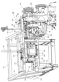
次に、図4~図8を参照してコンバインの駆動構造を説明する。図4及び図7に示す如
く、油圧直進ポンプ64a及び油圧直進モータ64bを有する走行変速用の直進油圧式無
段変速機64をミッションケース63に設ける。走行機体1前部の右側上面にエンジン7
を搭載し、エンジン7左側の走行機体1前部にミッションケース63を配置している。エ
ンジン7から左側方に突出させた出力軸65と、ミッションケース63から左側方に突出
させたミッション入力軸66を、エンジン出力ベルト67及びエンジン出力プーリ68及
びミッション入力プーリ69を介して連結している。加えて、昇降用油圧シリンダ4等を
駆動する作業部チャージポンプ59及び冷却ファン149をエンジン7に配置し、作業部
チャージポンプ59及び冷却ファン149をエンジン7にて駆動する。
Next, the drive structure of the combine harvester will be described with reference to Figures 4 to 8. As shown in Figures 4 and 7, a hydraulic linear pump 64a and a hydraulic linear motor 64b are provided in a transmission case 63. The engine 7 is mounted on the upper right side of the front part of the traveling body 1.
and a transmission case 63 is disposed in front of the traveling body 1 on the left side of the engine 7. An output shaft 65 protruding leftward from the engine 7 and a transmission input shaft 66 protruding leftward from the transmission case 63 are connected via an engine output belt 67, an engine output pulley 68, and a transmission input pulley 69. In addition, a working section charge pump 59 and a cooling fan 149 that drive the lifting hydraulic cylinder 4 and the like are disposed on the engine 7, and the working section charge pump 59 and the cooling fan 149 are driven by the engine 7.
また、油圧旋回ポンプ70a及び油圧旋回モータ70bを有する操舵用の旋回油圧式無
段変速機70をミッションケース63に設け、ミッション入力軸66を介して直進油圧式
無段変速機64と旋回油圧式無段変速機70にエンジン7の出力を伝達させる一方、操縦
ハンドル43と主変速レバー44及び副変速レバー45にて、直進油圧式無段変速機64
と旋回油圧式無段変速機70を出力制御し、直進油圧式無段変速機64と旋回油圧式無段
変速機70を介して左右の履帯2を駆動し、圃場内などを走行移動するように構成してい
る。実施形態では、ミッションケース63の右側面上部に直進及び旋回油圧式無段変速機
64,70を配置している。直進及び旋回油圧式無段変速機64,70とミッションケー
ス63とによって、本願発明の駆動装置を構成している。
A hydraulic swing pump 70a and a hydraulic swing motor 70b are provided in the transmission case 63. The output of the engine 7 is transmitted to the linear hydraulic continuously variable transmission 64 and the swing hydraulic continuously variable transmission 70 via the transmission input shaft 66. The steering handle 43, the main shift lever 44, and the sub shift lever 45 are used to control the linear hydraulic continuously variable transmission 64.
and the swing hydraulic continuously variable transmission 70 to drive the left and right crawlers 2 via the linear hydraulic continuously variable transmission 64 and the swing hydraulic continuously variable transmission 70, thereby traveling within a farm field, etc. In this embodiment, the linear and swing hydraulic continuously variable transmissions 64, 70 are disposed on the upper right side of the transmission case 63. The linear and swing hydraulic continuously variable transmissions 64, 70 and the transmission case 63 constitute the drive device of the present invention.
さらに、図1~図6に示す如く、扱胴軸20の前端側を軸支する扱胴駆動ケース71を
備える。脱穀部9の前面側に扱胴駆動ケース71を配置する。前記刈取部3と扱胴21を
駆動するための扱胴入力軸72を扱胴駆動ケース71に軸支する。また、脱穀部9の左右
に貫通させる一定回転軸としての主カウンタ軸76を備える。主カウンタ軸76の右側端
部に作業部入力プーリ83を設けている。エンジン7の出力軸65上のエンジン出力プー
リ68に、テンションローラを兼用した脱穀クラッチ84と作業部駆動ベルト85を介し
て、主カウンタ軸76の右側端部を連結している。
1 to 6, a threshing drum drive case 71 is provided which supports the front end of the threshing drum shaft 20. The threshing drum drive case 71 is disposed on the front side of the threshing unit 9. A threshing drum input shaft 72 for driving the reaping unit 3 and the threshing drum 21 is supported by the threshing drum drive case 71. A main counter shaft 76 is provided as a constant rotation shaft which passes through the threshing unit 9 from left to right. A working unit input pulley 83 is provided on the right end of the main counter shaft 76. The right end of the main counter shaft 76 is connected to the engine output pulley 68 on the output shaft 65 of the engine 7 via a threshing clutch 84 which also serves as a tension roller and a working unit drive belt 85.
扱胴21の前方に、走行機体1左右向きに延設された扱胴入力軸72と、走行機体1左
右向きに配置されたビータ18と、走行機体1左右向きに延設された刈取入力軸89を設
けている。扱胴入力軸72に主カウンタ軸76の駆動力を伝達する扱胴入力機構90とし
て、扱胴駆動プーリ86,87と扱胴駆動ベルト88を備え、エンジン7からの駆動力が
伝達される主カウンタ軸76のエンジン7側一端部に扱胴入力機構90(扱胴駆動プーリ
86,87と扱胴駆動ベルト88)を配置し、エンジン7の一定回転出力にて扱胴21を
一定回転駆動するように構成している。
Provided in front of the threshing drum 21 are a threshing drum input shaft 72 extending left and right from the traveling body 1, a beater 18 arranged left and right from the traveling body 1, and a reaping input shaft 89 extending left and right from the traveling body 1. As a threshing drum input mechanism 90 that transmits the driving force of the main counter shaft 76 to the threshing drum input shaft 72, threshing drum drive pulleys 86, 87 and a threshing drum drive belt 88 are provided, and the threshing drum input mechanism 90 (threshing drum drive pulleys 86, 87 and threshing drum drive belt 88) is arranged at one end of the main counter shaft 76 on the engine 7 side to which the driving force from the engine 7 is transmitted, so that the threshing drum 21 is driven to rotate at a constant speed by the constant rotation output of the engine 7.
主カウンタ軸76の駆動力をビータ軸82及び刈取入力軸89に伝達するビータ駆動機
構及び刈取駆動機構が、主カウンタ軸76の他端部側に設けられている。また、ビータ軸
82と主カウンタ軸76との間に副カウンタ軸104が配置されており、主カウンタ軸7
6及び副カウンタ軸104に設けた動力中継プーリ105,106に、動力中継ベルト1
13が巻回されて、刈取駆動機構へ動力を伝達する動力中継機構を構成している。
A beater drive mechanism and a reaping drive mechanism that transmit the driving force of the main counter shaft 76 to the beater shaft 82 and the reaping input shaft 89 are provided on the other end side of the main counter shaft 76. In addition, a sub-counter shaft 104 is disposed between the beater shaft 82 and the main counter shaft 76.
The power relay belt 1 is connected to the power relay pulleys 105 and 106 provided on the counter shaft 104 and the power relay pulleys 106 and 106 provided on the counter shaft 104.
13 is wound around the winding to form a power relay mechanism that transmits power to the reaping drive mechanism.
副カウンタ軸104及びビータ軸82それぞれに設けた刈取り駆動プーリ107,10
8に刈取り駆動ベルト114が巻回されて、ビータ駆動機構を構成している。そして、刈
取り駆動ベルト114が、テンションローラを兼用した刈取クラッチ109により張設さ
れることで、主カウンタ軸76に伝達されたエンジン7からの回転動力が動力中継機構及
びビータ駆動機構を介してビータ軸82に入力される。また、ビータ18が軸支されたビ
ータ軸82から、刈取駆動チェン115とスプロケット116,117を介して刈取入力
軸89にエンジン7からの刈取駆動力を伝達させるように、刈取駆動機構が構成されてい
る。これにより、刈取部3が、ビータ18と共にエンジン7の一定回転出力にて一定回転
駆動する。
The counter shaft 104 and the beater shaft 82 are provided with driving pulleys 107 and 10
A mowing drive belt 114 is wound around the main counter shaft 76 and constitutes a beater drive mechanism. The mowing drive belt 114 is tensioned by a mowing clutch 109 which also serves as a tension roller, so that the rotational power from the engine 7 transmitted to the main counter shaft 76 is input to the beater shaft 82 via the power relay mechanism and the beater drive mechanism. The mowing drive mechanism is configured so that the mowing drive force from the engine 7 is transmitted from the beater shaft 82, on which the beater 18 is journalled, to the mowing input shaft 89 via the mowing drive chain 115 and sprockets 116, 117. As a result, the mowing unit 3, together with the beater 18, is driven to rotate at a constant speed by the constant rotational output of the engine 7.
送風ファン状の唐箕29の回転軸である唐箕軸100が、中空の管形状を有しており、
唐箕軸100の中空部分に主カウンタ軸76が内挿されている。すなわち、主カウンタ軸
76と唐箕軸100とで二重軸構造を有しており、主カウンタ軸76と唐箕軸100とは
互いに相対回転可能に軸支されている。また、副カウンタ軸104及び唐箕軸100それ
ぞれに設けた唐箕駆動プーリ101,102に唐箕駆動ベルト103が巻回されて、唐箕
駆動機構を構成している。従って、主カウンタ軸76に伝達されたエンジン7からの回転
動力が動力中継機構及び唐箕駆動機構を介してビータ軸82に入力され、唐箕29がエン
ジン7の一定回転出力にて一定回転駆動する。
The winnowing shaft 100, which is the rotating shaft of the fan-shaped winnowing machine 29, has a hollow tubular shape.
The main counter shaft 76 is inserted into the hollow portion of the winnowing shaft 100. In other words, the main counter shaft 76 and the winnowing shaft 100 form a double shaft structure, and the main counter shaft 76 and the winnowing shaft 100 are supported so as to be rotatable relative to each other. A winnowing drive belt 103 is wound around winnowing drive pulleys 101, 102 provided on the sub-counter shaft 104 and the winnowing shaft 100, respectively, to form a winnowing drive mechanism. Therefore, the rotational power from the engine 7 transmitted to the main counter shaft 76 is input to the beater shaft 82 via the power relay mechanism and the winnowing drive mechanism, and the winnower 29 is driven to rotate at a constant speed by the constant rotational output of the engine 7.
さらに、脱穀部9の機筐体は、走行機体1上面側のうち、脱穀機筐支柱34前部の上面
側に刈取り支持枠体36を設置している。刈取り支持枠体36の前面右側に刈取り軸受体
37を取付け、刈取り支持枠体36の前面左側に後述する正逆転切換ケース121を取付
けている。そして、刈取り軸受体37と正逆転切換ケース121を介して、刈取り支持枠
体36の前面側に刈取入力軸89を走行機体1左右向きに回動可能に軸支すると共に、刈
取り支持枠体36の内部にビータ軸受体38を介して左右向きのビータ軸82(ビータ1
8)を回動可能に軸支している。また、刈取り支持枠体36の上面側に扱胴駆動ケース7
1を取付け、扱胴駆動ケース71に扱胴入力軸72を軸支している。
Furthermore, the machine housing of the threshing section 9 has a reaping support frame 36 installed on the top surface of the front part of the threshing machine housing support pillar 34, among the upper surface side of the traveling machine body 1. A reaping bearing body 37 is attached to the front right side of the reaping support frame 36, and a forward/reverse rotation changeover case 121, which will be described later, is attached to the front left side of the reaping support frame 36. The reaping input shaft 89 is journaled on the front side of the reaping support frame 36 via the reaping bearing body 37 and the forward/reverse rotation changeover case 121 so as to be rotatable left and right on the traveling machine body 1, and the left and right beater shaft 82 (beater 1) is connected to the inside of the reaping support frame 36 via the beater bearing body 38.
8) is rotatably supported.
1 is attached, and a threshing drum input shaft 72 is journalled on the threshing drum drive case 71.
一方、フィーダハウス11内の供給コンベヤ17を駆動する左右向きの刈取入力軸89
を備える。エンジン7から主カウンタ軸76におけるエンジン7側一端部に伝達された刈
取駆動力を、エンジン7とは反対側となる主カウンタ軸76の他端部から、刈取正逆転切
換ケース121の正逆転伝達軸122に伝達させる。刈取正逆転切換ケース121の正転
用ベベルギヤ124または逆転用ベベルギヤ125を介して刈取入力軸89を駆動する。
On the other hand, the left-right reaping input shaft 89 which drives the supply conveyor 17 in the feeder house 11
The mowing drive force transmitted from the engine 7 to one end of the main counter shaft 76 on the engine 7 side is transmitted from the other end of the main counter shaft 76 opposite the engine 7 to a forward/reverse transmission shaft 122 of a mowing forward/reverse rotation switching case 121. The mowing input shaft 89 is driven via a forward rotation bevel gear 124 or a reverse rotation bevel gear 125 of the mowing forward/reverse rotation switching case 121.
また、脱穀部9前側に左右向きの扱胴入力軸72が設けられ、エンジン7から主カウン
タ軸76におけるエンジン7側一端部に伝達された駆動力が、扱胴入力軸72におけるエ
ンジン7側一端部に伝達される。また、脱穀部9前側に設けた扱胴入力軸72が、走行機
体1左右向きに配置される一方、走行機体1前後向きに配置する扱胴軸20に扱胴21が
軸支されている。そして、扱胴入力軸72におけるエンジン7とは反対側となる左右他端
部にベベルギヤ機構75を介して扱胴軸20前端側が連結されている。主カウンタ軸76
におけるエンジン7とは反対側となる左右他端部から、脱穀後の穀粒を選別する穀粒選別
機構10または刈取部3にエンジン7の駆動力を伝達させるよう構成している。
A threshing drum input shaft 72 facing left and right is provided on the front side of the threshing section 9, and the driving force transmitted from the engine 7 to one end of the main counter shaft 76 on the engine 7 side is transmitted to one end of the threshing drum input shaft 72 on the engine 7 side. The threshing drum input shaft 72 provided on the front side of the threshing section 9 is arranged facing left and right with respect to the traveling body 1, while the threshing drum 21 is journaled on a threshing drum shaft 20 arranged in the front-rear direction of the traveling body 1. The front end of the threshing drum shaft 20 is connected via a bevel gear mechanism 75 to the other left and right end of the threshing drum input shaft 72 opposite the engine 7. The main counter shaft 76
The driving force of the engine 7 is transmitted from the other left and right ends, which are opposite the engine 7, to a grain sorting mechanism 10 that sorts grains after threshing or to the reaping unit 3.
即ち、エンジン7に近い側の主カウンタ軸76の右側端部に、扱胴駆動プーリ86,8
7と扱胴駆動ベルト88を介して、扱胴入力軸72の右側端部を連結する。左右方向に延
設した扱胴入力軸72の左側端部に、ベベルギヤ機構75を介して扱胴軸20の前端側を
連結する。主カウンタ軸76の右側端部から扱胴入力軸72を介して扱胴軸20の前端側
にエンジン7の動力を伝達させ、扱胴21を一方向に回転駆動させるように構成している
。一方、主カウンタ軸76の左側端部から、脱穀部9下方に配置した穀粒選別機構10に
、エンジン7の駆動力を伝達させるよう構成している。
That is, the right end of the main counter shaft 76 on the side close to the engine 7 is provided with a throttling drum drive pulley 86, 87.
The right end of the threshing drum input shaft 72 is connected via the engine 7 and a threshing drum drive belt 88. The front end of the threshing drum shaft 20 is connected via a bevel gear mechanism 75 to the left end of the threshing drum input shaft 72, which extends in the left-right direction. The power of the engine 7 is transmitted from the right end of the main counter shaft 76 to the front end of the threshing drum shaft 20 via the threshing drum input shaft 72, so as to drive the threshing drum 21 to rotate in one direction. Meanwhile, the driving force of the engine 7 is transmitted from the left end of the main counter shaft 76 to a grain sorting mechanism 10 disposed below the threshing section 9.
さらに、一番コンベヤ機構30の一番コンベヤ軸77の左側端部と、二番コンベヤ機構
31の二番コンベヤ軸78の左側端部とに、コンベヤ駆動ベルト111を介して主カウン
タ軸76の左側端部を連結している。揺動選別盤26後部を軸支したクランク状の揺動駆
動軸79の左側端部に揺動選別ベルト112を介して二番コンベヤ軸78の左側端部を連
結している。即ち、オペレータの脱穀クラッチレバー47操作によって、脱穀クラッチ8
4が入り切り制御される。脱穀クラッチ84の入り操作によって、穀粒選別機構10の各
部と扱胴21が駆動されるように構成している。
Furthermore, the left end of the main counter shaft 76 is connected to the left end of the first conveyor shaft 77 of the first conveyor mechanism 30 and the left end of the second conveyor shaft 78 of the second conveyor mechanism 31 via a conveyor drive belt 111. The left end of the second conveyor shaft 78 is connected to the left end of a crank-shaped oscillating drive shaft 79 that supports the rear part of the oscillating sorting board 26 via an oscillating sorting belt 112. That is, the threshing clutch 8 is engaged by operating the threshing clutch lever 47 by the operator.
The threshing clutch 84 is controlled to be turned on and off. By turning on the threshing clutch 84, each part of the grain sorting mechanism 10 and the threshing drum 21 are driven.
なお、一番コンベヤ軸77を介して揚穀コンベヤ32が駆動されて、一番コンベヤ機構
30の一番選別穀粒がグレンタンク6に収集される。また、二番コンベヤ軸78を介して
二番還元コンベヤ33が駆動されて、二番コンベヤ機構31の藁屑が混在した二番選別穀
粒(二番物)が揺動選別盤26の上面側に戻される。また、排塵口23に藁屑飛散用のス
プレッダ(図示省略)を設ける構造では、スプレッダ駆動プーリ(図示省略)とスプレッ
ダ駆動ベルト(図示省略)を介して、前記スプレッダに主カウンタ軸76の左側端部を連
結する。
The grain lifting conveyor 32 is driven via the first conveyor shaft 77, and the first sorted grains from the first conveyor mechanism 30 are collected in the grain tank 6. The second return conveyor 33 is driven via the second conveyor shaft 78, and the second sorted grains (second grains) mixed with straw dust from the second conveyor mechanism 31 are returned to the upper surface side of the oscillating sorting plate 26. In a structure in which a spreader (not shown) for scattering straw dust is provided at the dust outlet 23, the left end of the main counter shaft 76 is connected to the spreader via a spreader drive pulley (not shown) and a spreader drive belt (not shown).
供給コンベヤ17の送り終端側を軸支するコンベヤ入力軸としての刈取入力軸89を備
える。穀物ヘッダー12の右側部背面側にヘッダー駆動軸91を回転自在に軸支する。ビ
ータ軸82の左側端部に刈取駆動チェン115及びスプロケット116,117を介して
、正逆転伝達軸122の左側端部を連結し、刈取入力軸89が正逆転切換ケース121を
介して正逆転伝達軸122と連結している。また、ヘッダー駆動チェン118及びスプロ
ケット119,120を介して、左右方向に延設したヘッダー駆動軸91の左側端部に、
刈取入力軸89の右側端部を連結する。掻込みオーガ13を軸支する掻込み軸93を備え
る。掻込み軸93の右側部分に、掻込み駆動チェン92を介してヘッダー駆動軸91の中
間部を連結している。
The grain header 12 includes a reaping input shaft 89 that serves as a conveyor input shaft and supports the feeding end side of the supply conveyor 17. A header drive shaft 91 is rotatably supported on the rear side of the right side of the grain header 12. The left end of a forward/reverse rotation transmission shaft 122 is connected to the left end of the beater shaft 82 via a reaping drive chain 115 and sprockets 116, 117, and the reaping input shaft 89 is connected to the forward/reverse rotation transmission shaft 122 via a forward/reverse switching case 121. The left end of the header drive shaft 91, which extends in the left-right direction, is connected to the left end of the header drive shaft 91 via a header drive chain 118 and sprockets 119, 120.
The right end of the harvesting input shaft 89 is connected to the rear end of the harvesting input shaft 89. A raking shaft 93 is provided for supporting the raking auger 13. The middle portion of the header drive shaft 91 is connected to the right portion of the raking shaft 93 via a raking drive chain 92.
また、掻込みリール14を軸支するリール軸94を備える。リール軸94の右側端部に
、中間軸95及びリール駆動チェン96,97を介して掻込み軸93の右側端部を連結し
ている。ヘッダー駆動軸91の右側端部には、刈刃駆動クランク機構98を介して刈刃1
5が連結されている。刈取クラッチ109の入り切り操作によって、供給コンベヤ17と
、掻込みオーガ13と、掻込みリール14と、刈刃15が駆動制御されて、圃場の未刈り
穀稈の穂先側を連続的に刈取るように構成している。
The header drive shaft 91 also includes a reel shaft 94 that supports the pick-up reel 14. The right end of the reel shaft 94 is connected to the right end of the pick-up shaft 93 via an intermediate shaft 95 and reel drive chains 96, 97. The right end of the header drive shaft 91 is connected to the blade 1 via a blade drive crank mechanism 98.
5 is connected to the reaping clutch 109. By turning the reaping clutch 109 on and off, the supply conveyor 17, the raking auger 13, the raking reel 14, and the cutting blade 15 are driven and controlled to continuously reap the tips of the uncut stalks in the field.
なお、正逆転伝達軸122に一体形成する正転用ベベルギヤ124と、刈取入力軸89
に回転自在に軸支する逆転用ベベルギヤ125と、正転用ベベルギヤ124に逆転用ベベ
ルギヤ125を連結させる中間ベベルギヤ126を、正逆転切換ケース121に内設する
。正転用ベベルギヤ124と逆転用ベベルギヤ125に中間ベベルギヤ126を常に歯合
させる。一方、刈取入力軸89にスライダ127をスライド自在にスプライン係合軸支す
る。爪クラッチ形状の正転クラッチ128を介して正転用ベベルギヤ124にスライダ1
27を係脱可能に係合可能に構成すると共に、爪クラッチ形状の逆転クラッチ129を介
して逆転用ベベルギヤ125にスライダ127を係脱可能に係合可能に構成している。
In addition, the forward rotation bevel gear 124 formed integrally with the forward/reverse rotation transmission shaft 122 and the reaping input shaft 89
A reverse rotation bevel gear 125 rotatably supported on the forward rotation bevel gear 124, and an intermediate bevel gear 126 for connecting the reverse rotation bevel gear 125 to the forward rotation bevel gear 124 are disposed inside the forward/reverse rotation changeover case 121. The intermediate bevel gear 126 is always meshed with the forward rotation bevel gear 124 and the reverse rotation bevel gear 125. Meanwhile, a slider 127 is slidably supported on the reaping input shaft 89 by spline engagement. The slider 127 is connected to the forward rotation bevel gear 124 via a forward clutch 128 in the form of a claw clutch.
The slider 127 is configured to be releasably engageable with the reverse rotation bevel gear 125 via a reverse rotation clutch 129 in the form of a pawl clutch.
また、スライダ127を摺動操作する正逆転切換軸123を備え、正逆転切換軸123
に正逆転切換アーム130を設け、正逆転切換レバー(正逆転操作具)操作にて正逆転切
換アーム130を揺動させて、正逆転切換軸123を回動し、正転用ベベルギヤ124ま
たは逆転用ベベルギヤ125にスライダ127を接離させ、正転クラッチ128または逆
転クラッチ129を介して正転用ベベルギヤ124または逆転用ベベルギヤ125にスラ
イダ127を択一的に係止し、正逆転伝達軸122に刈取入力軸89を正転連結または逆
転連結させるように構成している。
In addition, a forward/reverse rotation switching shaft 123 that slides the slider 127 is provided.
A forward/reverse switching arm 130 is provided on the forward/reverse transmission shaft 122, and the forward/reverse switching arm 130 is swung by operating a forward/reverse switching lever (forward/reverse operating device) to rotate the forward/reverse switching shaft 123 and move the slider 127 closer to or away from the forward bevel gear 124 or the reverse bevel gear 125. The slider 127 is selectively engaged with the forward bevel gear 124 or the reverse bevel gear 125 via a forward clutch 128 or a reverse clutch 129, and the mowing input shaft 89 is connected in forward or reverse direction to the forward/reverse transmission shaft 122.
供給コンベヤ17を正転駆動または逆転駆動する正逆転切換機構としての正逆転切換ケ
ース121を備える構造であって、ビータ軸82に正逆転切換ケース121を介して供給
コンベヤ17を連結している。したがって、正逆転切換ケース121の逆転切換操作にて
フィーダハウス11の供給コンベヤ17などを逆転させることができ、フィーダハウス1
1内などの詰り藁を速やかに除去できる。
The structure includes a forward/reverse switching case 121 as a forward/reverse switching mechanism for driving the supply conveyor 17 in the forward or reverse direction, and the supply conveyor 17 is connected to the beater shaft 82 via the forward/reverse switching case 121. Therefore, the supply conveyor 17 of the feeder house 11 and the like can be reversed by the reverse switching operation of the forward/reverse switching case 121, and the feeder house 1
It can quickly remove any clogged straw inside the drain.
テンションプーリ状のオーガクラッチ156及びオーガ駆動ベルト157を介して、エ
ンジン7の出力軸65にオーガ駆動軸158の右側端部を連結する。オーガ駆動軸158
の左側端部にベベルギヤ機構159を介してグレンタンク6底部の横送りオーガ160前
端側を連結する。横送りオーガ160の後端側にベベルギヤ機構161を介して穀粒排出
コンベヤ8の縦送りオーガ162を連結し、縦送りオーガ162の上端側にベベルギヤ機
構163を介して穀粒排出コンベヤ8の穀粒排出オーガ164を連結する。また、オーガ
クラッチ156を入り切り操作する穀粒排出レバー155を備える。運転座席42後方で
あってグレンタンク6前面に穀粒排出レバー155を取付け、運転座席42側からオペレ
ータが穀粒排出レバー155を操作可能に構成している。
The right end of the auger drive shaft 158 is connected to the output shaft 65 of the engine 7 via a tension pulley-shaped auger clutch 156 and an auger drive belt 157.
The front end of a lateral feed auger 160 at the bottom of the grain tank 6 is connected to the left end of the lateral feed auger 160 via a bevel gear mechanism 159. A vertical feed auger 162 of the grain discharge conveyor 8 is connected to the rear end of the lateral feed auger 160 via a bevel gear mechanism 161, and a grain discharge auger 164 of the grain discharge conveyor 8 is connected to the upper end of the vertical feed auger 162 via a bevel gear mechanism 163. Also, a grain discharge lever 155 is provided for turning the auger clutch 156 on and off. The grain discharge lever 155 is attached to the front of the grain tank 6 behind the driver's seat 42, so that the operator can operate the grain discharge lever 155 from the driver's seat 42 side.
次に、図4及び図7などを参照して、ミッションケース63等の動力伝達構造を説明す
る。図4及び図7などに示す如く、ミッションケース63に、1対の直進ポンプ64a及
び直進モータ64bを有する直進(走行主変速)用の油圧式無段変速機64と、1対の旋
回ポンプ70a及び旋回モータ70bを有する旋回用の油圧式無段変速機70とを設ける
。直進ポンプ64a及び旋回ポンプ70aの各ポンプ軸258,259に、ミッションケ
ース63のミッション入力軸66をそれぞれギヤ連結させて駆動するように構成している
。ミッション入力軸66上のミッション入力プーリ69にエンジン出力ベルト67を掛け
回している。ミッション入力プーリ69にエンジン出力ベルト67を介してエンジン7の
出力を伝達し、直進ポンプ64a及び旋回ポンプ70aを駆動する。
Next, the power transmission structure of the transmission case 63 and the like will be described with reference to Figs. 4, 7, etc. As shown in Figs. 4, 7, etc., the transmission case 63 is provided with a hydraulic continuously variable transmission 64 for straight travel (main travel speed change) having a pair of straight pumps 64a and straight motors 64b, and a hydraulic continuously variable transmission 70 for swinging having a pair of swing pumps 70a and swing motors 70b. The transmission input shaft 66 of the transmission case 63 is gear-coupled to each of the pump shafts 258, 259 of the straight pumps 64a and the swing pumps 70a, respectively, to drive them. An engine output belt 67 is wound around a mission input pulley 69 on the mission input shaft 66. The output of the engine 7 is transmitted to the mission input pulley 69 via the engine output belt 67 to drive the straight pump 64a and the swing pump 70a.
エンジン7の出力軸65から出力される駆動力は、エンジン出力ベルト67及びミッシ
ョン入力軸66を介して、直進ポンプ64aのポンプ軸258及び旋回ポンプ70aのポ
ンプ軸259にそれぞれ伝達される。直進油圧式無段変速機64では、ポンプ軸258に
伝達された動力にて、直進ポンプ64aから直進モータ64bに向けて作動油が適宜送り
込まれる。同様に、旋回油圧式無段変速機70では、ポンプ軸259に伝達された動力に
て、旋回ポンプ70aから旋回モータ70bに向けて作動油が適宜送り込まれる。
The driving force output from the output shaft 65 of the engine 7 is transmitted to a pump shaft 258 of the linear pump 64a and a pump shaft 259 of the swing pump 70a via an engine output belt 67 and a transmission input shaft 66. In the linear hydraulic continuously variable transmission 64, hydraulic oil is appropriately sent from the linear pump 64a to the linear motor 64b by the power transmitted to the pump shaft 258. Similarly, in the swing hydraulic continuously variable transmission 70, hydraulic oil is appropriately sent from the swing pump 70a to the swing motor 70b by the power transmitted to the pump shaft 259.
ミッション入力軸66は、ミッションケース63左側面上部からフィーダハウス11に
向かって突出しており、ミッション入力軸66の突出端(左端)にミッション入力プーリ
69を相対回転不能に軸着している。ミッション入力軸66は、ミッションケース63に
固定された軸受で回転可能に軸支されており、ミッション入力軸66の中途部に動力分配
ギヤ262が相対回転不能に嵌着されている。直進ポンプ64aのポンプ軸258と旋回
ポンプ70aのポンプ軸259それぞれが、平面視でミッション入力軸66の前後に振り
分け配置されるとともに、側面視でミッション入力軸66の下方に配置される。
The transmission input shaft 66 protrudes from the upper left side surface of the transmission case 63 toward the feeder house 11, and a transmission input pulley 69 is axially attached to the protruding end (left end) of the transmission input shaft 66 so as not to rotate relative to the transmission input pulley 69. The transmission input shaft 66 is rotatably supported by a bearing fixed to the transmission case 63, and a power distribution gear 262 is fitted to the middle portion of the transmission input shaft 66 so as not to rotate relative to the transmission input pulley 69. A pump shaft 258 of the linear pump 64a and a pump shaft 259 of the rotary pump 70a are respectively arranged in front of and behind the transmission input shaft 66 in a plan view, and are arranged below the mission input shaft 66 in a side view.
無段変速ケース323からミッションケース63内に向かって突出させたポンプ軸25
8の突出端(左端)には、ミッション入力軸66に固定された動力分配ギヤ262と噛合
する直進入力ギヤ263が相対回転不能に嵌着されている。同様に、無段変速ケース32
3からミッションケース63内に向かって突出させたポンプ軸259の突出端(左端)に
は、ミッション入力軸66に固定された動力分配ギヤ262と噛合する旋回入力ギヤ26
4が相対回転不能に嵌着されている。
The pump shaft 25 protrudes from the continuously variable transmission case 323 toward the inside of the transmission case 63.
A linear input gear 263 that meshes with a power distribution gear 262 fixed to the transmission input shaft 66 is fitted to the protruding end (left end) of the continuously variable transmission case 32 so as not to rotate relative to the transmission input shaft 66.
The pump shaft 259 is protruded from the transmission case 63 into the transmission case 63 at its protruding end (left end) thereof. The protruding end (left end) of the pump shaft 259 is fitted with a rotation input gear 262 which is engaged with a power distribution gear 262 fixed to the transmission input shaft 66.
4 are fitted to each other so as not to rotate relative to each other.
エンジン7の出力軸65から出力される駆動力がミッション入力プーリ69に伝達され
ると、ミッション入力プーリ69と共にミッション入力軸66及び動力分配ギヤ262が
回転して、直進入力ギヤ263を介して、直進ポンプ64aのポンプ軸258を回転させ
る一方、旋回入力ギヤ264を介して、旋回ポンプ70aのポンプ軸259を回転させる
。即ち、ポンプ軸258,259の間に配置されたミッション入力軸66の動力分配ギヤ
262に、ポンプ軸258,259それぞれの直進入力ギヤ263及び旋回入力ギヤ26
4を噛合させることで、エンジン7からの駆動力を直進油圧式無段変速機64及び旋回油
圧式無段変速機70それぞれに効率よく伝達できる。
When the driving force output from the output shaft 65 of the engine 7 is transmitted to the transmission input pulley 69, the transmission input shaft 66 and the power distribution gear 262 rotate together with the transmission input pulley 69, rotating the pump shaft 258 of the linear pump 64a via the linear input gear 263, while rotating the pump shaft 259 of the swirl pump 70a via the swirl input gear 264. That is, the power distribution gear 262 of the transmission input shaft 66, which is disposed between the pump shafts 258, 259, is connected to the linear input gears 263 and the swirl input gears 264 of the pump shafts 258, 259.
By meshing the gears 4, the driving force from the engine 7 can be efficiently transmitted to the linear hydraulic continuously variable transmission 64 and the turning hydraulic continuously variable transmission 70, respectively.
なお、ポンプ軸259には、各油圧ポンプ64a,70a及び各油圧モータ64b,7
0bに作動油を供給するための変速機チャージポンプ151が取付けられている。直進油
圧式無段変速機64は、操縦コラム41に配置された主変速レバー44や操縦ハンドル4
3の操作量に応じて、直進ポンプ64aにおける回転斜板の傾斜角度を変更調節して、直
進モータ64bへの作動油の吐出方向及び吐出量を変更することにより、直進モータ64
bから突出した直進用モータ軸260の回転方向及び回転数を任意に調節するように構成
されている。
The pump shaft 259 is connected to the hydraulic pumps 64a, 70a and the hydraulic motors 64b, 7
The linear hydraulic continuously variable transmission 64 is operated by the main speed change lever 44 and the steering handle 46 disposed in the steering column 41.
The inclination angle of the swash plate in the linear pump 64a is changed and adjusted in accordance with the amount of operation of the linear motor 64.3, thereby changing the discharge direction and discharge amount of the hydraulic oil to the linear motor 64b.
The rotation direction and rotation speed of the linear motion motor shaft 260 protruding from b can be arbitrarily adjusted.
直進用モータ軸260の回転動力は、直進伝達ギヤ機構250から副変速ギヤ機構25
1に伝達される。副変速ギヤ機構251は、副変速シフタ252,253によって切換え
る副変速低速ギヤ254及び副変速中速ギヤ255及び副変速高速ギヤ256を有する。
操縦コラム41に配置された副変速レバー45の操作にて、直進用モータ軸260の出力
回転数を低速又は中速又は高速という3段階の変速段に択一的に切換えるように構成して
いる。なお、副変速の低速と中速と高速との間には、中立位置(副変速の出力が零になる
位置)を有している。
The rotational power of the linear motor shaft 260 is transmitted from the linear transmission gear mechanism 250 to the sub-transmission gear mechanism 25
The auxiliary transmission gear mechanism 251 has an auxiliary low speed gear 254, an auxiliary medium speed gear 255, and an auxiliary high speed gear 256 which are switched by auxiliary transmission shifters 252, 253.
The output speed of the straight-travel motor shaft 260 is selectively switched to one of three speed stages, low speed, medium speed, or high speed, by operating the auxiliary speed change lever 45 disposed on the steering column 41. Note that the auxiliary speed change has a neutral position (a position where the output of the auxiliary speed change is zero) between low speed, medium speed, and high speed.
副変速ギヤ機構251の出力側に設けられた駐車ブレーキ軸265(副変速出力軸)に
は、ドラム式の駐車ブレーキ266が設けられている。副変速ギヤ機構251からの回転
動力は、駐車ブレーキ軸265に固着された副変速出力ギヤ267から左右の差動機構2
57に伝達される。左右の差動機構257には、遊星ギヤ機構268をそれぞれ備えてい
る。また、駐車ブレーキ軸265上に直進用パルス発生回転輪体292を設け、図示しな
い直進車速センサによって、直進出力の回転数(直進車速=副変速出力ギヤ267の変速
出力)を検出するように構成している。
A parking brake shaft 265 (sub-transmission output shaft) provided on the output side of the sub-transmission gear mechanism 251 is provided with a drum-type parking brake 266. The rotational power from the sub-transmission gear mechanism 251 is transmitted from a sub-transmission output gear 267 fixed to the parking brake shaft 265 to the left and right differential mechanisms 2.
The right and left differential mechanisms 257 are each equipped with a planetary gear mechanism 268. In addition, a straight-line pulse generating rotating wheel 292 is provided on the parking brake shaft 265, and a straight-line output rotation speed (straight-line vehicle speed = shift output of the sub-transmission output gear 267) is detected by a straight-line vehicle speed sensor (not shown).
左右各遊星ギヤ機構268は、1つのサンギヤ271と、サンギヤ271に噛合う複数
の遊星ギヤ272と、遊星ギヤ272に噛合うリングギヤ273と、複数の遊星ギヤ27
2を同一円周上に回転可能に配置するキャリヤ274とをそれぞれ備えている。左右の遊
星ギヤ機構268のキャリヤ274は、同一軸線上において適宜間隔を設けて相対向させ
て配置されている。左右のサンギヤ271が設けられたサンギヤ軸275にセンタギヤ2
76を固着している。
Each of the left and right planetary gear mechanisms 268 includes a sun gear 271, a plurality of planetary gears 272 meshing with the sun gear 271, a ring gear 273 meshing with the planetary gears 272, and a plurality of planetary gears 273.
The carriers 274 of the left and right planetary gear mechanisms 268 are disposed facing each other on the same axis with an appropriate gap provided.
76 is fixed.
左右の各リングギヤ273は、その内周面の内歯を複数の遊星ギヤ272に噛合わせた
状態で、サンギヤ軸275に同心状に配置されている。また、左右の各リングギヤ273
外周面の外歯は、後述する左右旋回出力用の中間ギヤ287,288を介して、操向出力
軸285に連結させている。各リングギヤ273は、キャリヤ274の外側面から左右外
向きに突出した左右の強制デフ出力軸277に回転可能に軸支されている。左右の強制デ
フ出力軸277に、ファイナルギヤ278a,278bを介して左右の車軸278が連結
されている。左右の車軸278には左右の駆動スプロケット51が取付けられている。従
って、副変速ギヤ機構251から左右の遊星ギヤ機構268に伝達された回転動力は、左
右の車軸278から各駆動スプロケット51に同方向の同一回転数にて伝達され、左右の
履帯2を同方向の同一回転数にて駆動して、走行機体1を直進(前進、後退)移動させる
。
Each of the left and right ring gears 273 is disposed concentrically about the sun gear shaft 275 with the inner teeth of the inner peripheral surface of the ring gear 273 meshing with the planetary gears 272.
The external teeth on the outer circumferential surface are connected to a steering output shaft 285 via intermediate gears 287, 288 for left and right turning output, which will be described later. Each ring gear 273 is rotatably supported by left and right forced differential output shafts 277 protruding outwardly to the left and right from the outer surface of the carrier 274. Left and right axles 278 are connected to the left and right forced differential output shafts 277 via final gears 278a, 278b. Left and right drive sprockets 51 are attached to the left and right axles 278. Therefore, the rotational power transmitted from the auxiliary transmission gear mechanism 251 to the left and right planetary gear mechanisms 268 is transmitted from the left and right axles 278 to the respective drive sprockets 51 at the same rotational speed in the same direction, driving the left and right crawlers 2 at the same rotational speed in the same direction, and moving the traveling body 1 straight (forward, backward).
旋回油圧式無段変速機70は、操縦コラム41に配置された主変速レバー44や操縦ハ
ンドル43の回動操作量に応じて、旋回ポンプ70aにおける回転斜板の傾斜角度を変更
調節して、旋回モータ70bへの作動油の吐出方向及び吐出量を変更することにより、旋
回モータ70bから突出した旋回用モータ軸261の回転方向及び回転数を任意に調節す
るように構成されている。また、後述する操向カウンタ軸280上に旋回用パルス発生回
転輪体294を設け、図示しない旋回用回転センサ(旋回車速センサ)にて、旋回モータ
70bの操向出力の回転数(旋回車速)を検出するように構成している。
The swing hydraulic continuously variable transmission 70 is configured to arbitrarily adjust the rotation direction and rotation speed of the swing motor shaft 261 protruding from the swing motor 70b by changing and adjusting the inclination angle of the rotating swash plate in the swing pump 70a in accordance with the amount of rotation of the main speed change lever 44 and the steering handle 43 arranged on the steering column 41, thereby changing the discharge direction and discharge amount of hydraulic oil to the swing motor 70b. In addition, a swing pulse generating rotating wheel 294 is provided on the steering counter shaft 280 described later, and a swing rotation sensor (swing vehicle speed sensor) not shown is configured to detect the rotation speed (swing vehicle speed) of the steering output of the swing motor 70b.
また、ミッションケース63内には、旋回用モータ軸261(操向入力軸)上に設ける
湿式多板形の旋回ブレーキ279(操向ブレーキ)と、旋回用モータ軸261に減速ギヤ
281を介して連結する操向カウンタ軸280と、操向カウンタ軸280に減速ギヤ28
6を介して連結する操向出力軸285と、左リングギヤ273に逆転ギヤ284を介して
操向出力軸285を連結する左入力ギヤ機構282と、右リングギヤ273に操向出力軸
285を連結する右入力ギヤ機構283とを設けている。旋回用モータ軸261の回転動
力は、操向カウンタ軸280に伝達される。操向カウンタ軸280に伝達された回転動力
は、左の入力ギヤ機構282における操向出力軸285上の左中間ギヤ287と逆転ギヤ
284を介して逆転回転動力として、左のリングギヤ273に伝達される一方、右の入力
ギヤ機構283における操向出力軸285上の右中間ギヤ288を介して正転回転動力と
して、右のリングギヤ273に伝達される。
Also, within the transmission case 63, there are disposed a wet-type multi-plate swing brake 279 (steering brake) provided on the swing motor shaft 261 (steering input shaft), a steering counter shaft 280 connected to the swing motor shaft 261 via a reduction gear 281, and a reduction gear 282 connected to the steering counter shaft 280.
6, a left input gear mechanism 282 which connects the steering output shaft 285 to the left ring gear 273 via a reverse gear 284, and a right input gear mechanism 283 which connects the steering output shaft 285 to the right ring gear 273. The rotational power of the turning motor shaft 261 is transmitted to a steering countershaft 280. The rotational power transmitted to the steering countershaft 280 is transmitted to the left ring gear 273 as reverse rotational power via a left intermediate gear 287 on the steering output shaft 285 in the left input gear mechanism 282 and a reverse gear 284, and is transmitted to the right ring gear 273 as forward rotational power via a right intermediate gear 288 on the steering output shaft 285 in the right input gear mechanism 283.
副変速ギヤ機構251を中立にした場合は、直進モータ64bから左右の遊星ギヤ機構
268への動力伝達が阻止される。副変速ギヤ機構251から中立以外の副変速出力時に
、副変速低速ギヤ254又は副変速中速ギヤ255又は副変速高速ギヤ256を介して直
進モータ64bから左右の遊星ギヤ機構268へ動力伝達される。一方、旋回ポンプ70
aの出力をニュートラル状態とし、且つ旋回ブレーキ279を入り状態とした場合は、旋
回モータ70bから左右の遊星ギヤ機構268への動力伝達が阻止される。旋回ポンプ7
0aの出力をニュートラル以外の状態とし、且つ旋回ブレーキ279を切り状態とした場
合は、旋回モータ70bの回転動力が、左入力ギヤ機構282及び逆転ギヤ284を介し
て左リングギヤ273に伝達される一方、右入力ギヤ機構283を介して右リングギヤ2
73に伝達される。
When the sub-transmission gear mechanism 251 is in neutral, power transmission from the linear motor 64b to the left and right planetary gear mechanisms 268 is blocked. When the sub-transmission gear mechanism 251 outputs a sub-transmission output other than neutral, power is transmitted from the linear motor 64b to the left and right planetary gear mechanisms 268 via the sub-transmission low speed gear 254, the sub-transmission medium speed gear 255, or the sub-transmission high speed gear 256. On the other hand, the swing pump 70
When the output of the swing pump 7 a is in a neutral state and the swing brake 279 is in an on state, the power transmission from the swing motor 70 b to the left and right planetary gear mechanisms 268 is blocked.
When the output of the swing motor 70a is in a state other than neutral and the swing brake 279 is in an off state, the rotational power of the swing motor 70b is transmitted to the left ring gear 273 via the left input gear mechanism 282 and the reverse gear 284, while the rotational power of the swing motor 70b is transmitted to the right ring gear 273 via the right input gear mechanism 283.
This will be transmitted to 73.
その結果、旋回モータ70bの正回転(逆回転)時は、互いに逆方向の同一回転数で、
左リングギヤ273が逆転(正転)し、右リングギヤ273が正転(逆転)する。即ち、
各モータ軸260,261からの変速出力は、副変速ギヤ機構251又は差動機構257
をそれぞれ経由して、左右の履帯2の駆動スプロケット51にそれぞれ伝達され、走行機
体1の車速(走行速度)及び進行方向が決定される。
As a result, when the swing motor 70b rotates forward (reversely), the rotation speeds are the same but in opposite directions.
The left ring gear 273 rotates in the reverse direction (forward rotation), and the right ring gear 273 rotates in the forward direction (reverse rotation).
The speed change output from each motor shaft 260, 261 is sent to the sub-speed change gear mechanism 251 or the differential mechanism 257.
The signal is then transmitted to the drive sprockets 51 of the left and right crawlers 2 via the drive shafts 51 and 52, respectively, to determine the vehicle speed (traveling speed) and direction of travel of the traveling machine body 1.
すなわち、旋回モータ70bを停止させて左右リングギヤ273を静止固定させた状態
で、直進モータ64bが駆動すると、直進用モータ軸260からの回転出力は左右サンギ
ヤ271に左右同一回転数で伝達され、遊星ギヤ272及びキャリヤ274を介して、左
右の履帯2が同方向の同一回転数にて駆動され、走行機体1が直進走行する。
In other words, when the slewing motor 70b is stopped and the left and right ring gears 273 are fixed stationary, when the straight-line motor 64b is driven, the rotational output from the straight-line motor shaft 260 is transmitted to the left and right sun gears 271 at the same rotation speed on the left and right, and via the planetary gears 272 and carrier 274, the left and right tracks 2 are driven at the same rotation speed in the same direction, causing the running body 1 to run in a straight line.
逆に、直進モータ64bを停止させて左右サンギヤ271を静止固定させた状態で、旋
回モータ70bを駆動させると、旋回用モータ軸261からの回転動力にて、左のリング
ギヤ273が正回転(逆回転)し、右のリングギヤ273は逆回転(正回転)する。その
結果、左右の履帯2の駆動スプロケット51のうち、一方が前進回転し、他方が後退回転
し、走行機体1はその場で方向転換(信地旋回スピンターン)される。
Conversely, when the slewing motor 70b is driven with the linear motor 64b stopped and the left and right sun gears 271 fixed stationary, the left ring gear 273 rotates forward (reverse) and the right ring gear 273 rotates reverse (forward) due to the rotational power from the slewing motor shaft 261. As a result, one of the drive sprockets 51 of the left and right tracks 2 rotates forward and the other rotates backward, causing the running body 1 to change direction on the spot (spin turn).
また、直進モータ64bによって左右サンギヤ271を駆動しながら、旋回モータ70
bによって左右リングギヤ273を駆動することによって、左右の履帯2の速度に差が生
じ、走行機体1は前進又は後退しながら信地旋回半径より大きい旋回半径で左又は右に旋
回(Uターン)する。このときの旋回半径は左右の履帯2の速度差に応じて決定される。
エンジン7の走行駆動力が左右の履帯2に常に伝達された状態で左又は右に旋回移動する
。
In addition, the left and right sun gears 271 are driven by the linear motor 64b, while the swing motor 70
By driving the left and right ring gears 273 by b, a difference in speed occurs between the left and right crawlers 2, and the traveling body 1 turns left or right (makes a U-turn) with a turning radius larger than the pivot turning radius while moving forward or backward. The turning radius at this time is determined according to the speed difference between the left and right crawlers 2.
The vehicle turns left or right while the driving force of the engine 7 is constantly transmitted to the left and right crawlers 2 .
次いで、図8~図15を参照して、本実施形態の普通型コンバインにおける作業系油圧
回路180及び走行系油圧回路200について説明する。図8~図12に示す如く、作業
系油圧回路180は、油圧アクチュエータとして、刈取昇降用油圧シリンダ4と、掻込み
リール14を昇降可能に支持する左右のリール昇降用油圧シリンダ27L,27Rと、穀
粒排出オーガ164を昇降可能に支持するオーガ昇降用油圧シリンダ55と、走行機体1
を昇降させる左右の機体昇降用油圧シリンダ56L,56Rと、作動油を貯留する作動油
タンク57と、作動油タンク57とストレーナ58を介して接続した作業部チャージポン
プ59と、作動油の流れを切り換える油圧バルブ60A~60Eと、油圧バルブ50A~
60Eから作動油タンク57への戻り配管途上に設けられるオイルクーラ62とを備える
。なお、油圧バルブ60A~60Eは、走行機体1上に搭載される油圧バルブユニット6
0に組み込まれている。
Next, a working hydraulic circuit 180 and a traveling hydraulic circuit 200 in the normal type combine harvester of this embodiment will be described with reference to Figures 8 to 15. As shown in Figures 8 to 12, the working hydraulic circuit 180 includes, as hydraulic actuators, a reaping lifting hydraulic cylinder 4, left and right reel lifting hydraulic cylinders 27L, 27R that support the raking reel 14 so that it can be raised and lowered, an auger lifting hydraulic cylinder 55 that supports the grain discharge auger 164 so that it can be raised and lowered, and a traveling machine body 1
a hydraulic oil tank 57 for storing hydraulic oil; a working section charge pump 59 connected to the hydraulic oil tank 57 via a strainer 58; hydraulic valves 60A to 60E for switching the flow of hydraulic oil; and hydraulic valves 50A to
The hydraulic valves 60A to 60E are provided with an oil cooler 62 provided in the return pipe from the hydraulic valve unit 60A to the hydraulic oil tank 57.
It is built into 0.
刈取昇降用油圧バルブ60Aを介して、刈取昇降用油圧シリンダ4に作業部チャージポ
ンプ59を油圧接続する。運転操作部(運転台)5における刈取姿勢レバー(図示省略)
を前後方向に傾倒させる操作によって、刈取昇降用油圧シリンダ4を作動させ、オペレー
タが刈取部3を任意高さ(例えば刈取り作業高さまたは非作業高さ等)に昇降動させるよ
うに構成している。一方、リール昇降用油圧バルブ60Bを介して、リール昇降用油圧シ
リンダ27L,27Rに作業部チャージポンプ59を油圧接続する。上記刈取姿勢レバー
(図示省略)を左右方向に傾倒させる操作などによって、リール昇降用油圧シリンダ27
L,27Rを作動させ、オペレータが掻込みリール14を任意高さに昇降動させ、圃場の
未刈り穀稈を刈取るように構成している。
A working unit charge pump 59 is hydraulically connected to the hydraulic cylinder 4 for lifting and lowering the reaper via a hydraulic valve 60A for lifting and lowering the reaper. A reaping position lever (not shown) in the driving operation unit (driver's seat) 5
The operator is configured to raise and lower the cutting unit 3 to a desired height (e.g., cutting work height or non-work height) by tilting the cutting position lever (not shown) forward and backward, thereby operating the cutting lifting hydraulic cylinder 4, and the operator is configured to raise and lower the cutting unit 3 to a desired height (e.g., cutting work height or non-work height, etc.). Meanwhile, a working unit charge pump 59 is hydraulically connected to the reel lifting hydraulic cylinders 27L, 27R via a reel lifting hydraulic valve 60B. The reel lifting hydraulic cylinders 27L, 27R are operated by tilting the cutting position lever (not shown) forward and backward, etc.
By operating the reel 27L, 27R, the operator can raise and lower the raking reel 14 to the desired height to harvest the uncut stalks in the field.
オーガ昇降用油圧バルブ60Cを介して、オーガ昇降用油圧シリンダ55に作業部チャ
ージポンプ59を油圧接続する。運転操作部(運転台)5における穀粒排出レバー155
を前後方向に傾倒させる操作によって、オーガ昇降用油圧シリンダ55を作動させ、オペ
レータが穀粒排出コンベヤ8における穀粒排出オーガ164の籾投げ口を任意高さに昇降
動させる。なお、電動モータ165によって縦送りオーガ162及びベベルギヤ機構16
3と共に穀粒排出オーガ164を水平方向に回動させて、籾投げ口を横方向に移動させる
。即ち、トラック荷台またはコンテナの上方に籾投げ口を位置させ、トラック荷台または
コンテナ内にグレンタンク6内の穀粒を排出するように構成している。
A working section charge pump 59 is hydraulically connected to the auger lifting hydraulic cylinder 55 via the auger lifting hydraulic valve 60C.
The operator operates the hydraulic cylinder 55 for lifting and lowering the auger by tilting the auger 164 forward and backward, and raises and lowers the rice-throwing opening of the grain discharge auger 164 on the grain discharge conveyor 8 to a desired height.
The grain discharge auger 164 is rotated horizontally together with the grain tank 6 to move the rice throwing opening laterally. That is, the rice throwing opening is positioned above the truck bed or container, and the grains in the grain tank 6 are discharged into the truck bed or container.
左機体昇降用油圧バルブ60Dを介して、左機体昇降用油圧シリンダ56Lに作動油タ
ンク57及び作業部チャージポンプ59を油圧接続する。一方、右機体昇降用油圧バルブ
60Eを介して、右機体昇降用油圧シリンダ56Rに作動油タンク57及び作業部チャー
ジポンプ59を油圧接続する。左右の機体昇降用油圧シリンダ56L,56Rは互いに独
立的に作動させることにより、走行機体1の左右を独立的に昇降させる。
The hydraulic oil tank 57 and the working unit charge pump 59 are hydraulically connected to the left machine body lifting hydraulic cylinder 56L via the left machine body lifting hydraulic valve 60D. Meanwhile, the hydraulic oil tank 57 and the working unit charge pump 59 are hydraulically connected to the right machine body lifting hydraulic cylinder 56R via the right machine body lifting hydraulic valve 60E. The left and right machine body lifting hydraulic cylinders 56L, 56R are operated independently of each other to lift and lower the left and right running machine body 1 independently.
従って、左右両側の機体昇降用油圧シリンダ56L,56Rを同時に作動して、左右の
トラックフレーム50,50を走行機体1に対して同時に下げると、走行機体1は左右両
側の履帯2,2接地部に対して上方に離れて(上昇し)、走行機体1の履帯2,2接地部
に対する相対高さ(車高)は高くなる。逆に、左右のトラックフレーム50,50を走行
機体1に対して同時に上げると、走行機体1は左右両側の履帯2,2接地部に対して近づ
いて(下降し)、走行機体1の履帯2,2接地部に対する相対高さ(車高)は低くなる。
Therefore, when the left and right vehicle body lifting hydraulic cylinders 56L, 56R are simultaneously operated to simultaneously lower the left and right track frames 50, 50 relative to the traveling vehicle body 1, the traveling vehicle body 1 moves away (rises) from the ground contact portions of the left and right tracks 2, 2, and the relative height (vehicle height) of the traveling vehicle body 1 to the ground contact portions of the tracks 2, 2 becomes higher. Conversely, when the left and right track frames 50, 50 are simultaneously raised relative to the traveling vehicle body 1, the traveling vehicle body 1 moves closer (descends) to the ground contact portions of the left and right tracks 2, 2, and the relative height (vehicle height) of the traveling vehicle body 1 to the ground contact portions of the tracks 2, 2 becomes lower.
そして、左機体昇降用油圧シリンダ56Lを作動して左トラックフレーム50を走行機
体1に対して下げる、または右機体昇降用油圧シリンダ56Rを作動して右トラックフレ
ーム50を走行機体1に対して上げると(もしくはこの両方の動作を同時に実行しても)
、走行機体1は右下がりに傾斜する。逆に、右機体昇降用油圧シリンダ56Rを作動して
右トラックフレーム50を走行機体1に対して下げる、または左機体昇降用油圧シリンダ
56Lを作動して右トラックフレーム50を走行機体1に対して上げると(もしくはこの
両方の動作を同時に実行しても)、走行機体1は左下がりに傾斜する。
Then, the left vehicle body lifting hydraulic cylinder 56L is operated to lower the left track frame 50 relative to the traveling vehicle body 1, or the right vehicle body lifting hydraulic cylinder 56R is operated to raise the right track frame 50 relative to the traveling vehicle body 1 (or both of these operations can be performed simultaneously).
Conversely, when the right body lifting hydraulic cylinder 56R is operated to lower the right track frame 50 relative to the traveling body 1, or when the left body lifting hydraulic cylinder 56L is operated to raise the right track frame 50 relative to the traveling body 1 (or when both of these operations are performed simultaneously), the traveling body 1 is tilted downward to the left.
作動油タンク57、作業部チャージポンプ59、及び油圧バルブユニット60はそれぞ
れ、走行機体1上に搭載されており、油圧配管181~183を介して互いに連結してい
る。走行機体1上において、作動油タンク57が前方左側に設置される一方、前方右側に
搭載されたエンジン7前面に作業部チャージポンプ59が固定され、作動油タンク57に
内装されているストレーナ58と作業部チャージポンプ59とが油圧配管181により連
結している。また、走行機体1上において、エンジン7後方となる位置に油圧バルブユニ
ット60が配置されており、作業部チャージポンプ59の吐出側が油圧配管182を介し
て油圧バルブユニット60に連結している。更に、油圧バルブユニット60は、作動油戻
し管となる油圧配管183及びオイルクーラ62を介して作動油タンク57と連結してい
る。
The hydraulic oil tank 57, the working section charge pump 59, and the hydraulic valve unit 60 are mounted on the traveling machine body 1, and are connected to each other via hydraulic piping 181 to 183. On the traveling machine body 1, the hydraulic oil tank 57 is installed on the front left side, while the working section charge pump 59 is fixed to the front of the engine 7 mounted on the front right side, and the strainer 58 built in the hydraulic oil tank 57 and the working section charge pump 59 are connected by hydraulic piping 181. In addition, on the traveling machine body 1, the hydraulic valve unit 60 is disposed at a position behind the engine 7, and the discharge side of the working section charge pump 59 is connected to the hydraulic valve unit 60 via hydraulic piping 182. Furthermore, the hydraulic valve unit 60 is connected to the hydraulic oil tank 57 via hydraulic piping 183, which serves as a hydraulic oil return pipe, and an oil cooler 62.
作動油タンク57は、走行機体1上であってフィーダハウス11及びビータ18で囲ま
れた空間位置に設置され、エンジン7と作動油タンク57とが走行機体1前方で左右に並
んで配置されている。すなわち、フィーダハウス11と脱穀部9の機筐体とで囲まれた空
間に作動油タンク57が配置されることとなり、刈取部3からの塵埃が作動油タンク57
に堆積することを抑制でき、給油口184などからの塵埃の侵入による作動油の汚染も防
止できる。また、エンジン7からの冷却風が作動油タンク57の設置空間に流れることに
より、作業系油圧回路180上にオイルクーラを設けずとも作動油温度の上昇を抑制する
ことができ、各油圧部材を適正に駆動できる。
The hydraulic oil tank 57 is installed on the traveling body 1 in a space surrounded by the feeder house 11 and the beater 18, and the engine 7 and the hydraulic oil tank 57 are arranged side by side on the left and right in front of the traveling body 1. In other words, the hydraulic oil tank 57 is arranged in the space surrounded by the feeder house 11 and the machine housing of the threshing section 9, and dust from the reaping section 3 is trapped in the hydraulic oil tank 57.
This can prevent contamination of the hydraulic oil due to dust entering through the fuel filler port 184, etc. In addition, since the cooling air from the engine 7 flows into the installation space of the hydraulic oil tank 57, an increase in the hydraulic oil temperature can be suppressed without providing an oil cooler on the working hydraulic circuit 180, and each hydraulic member can be driven appropriately.
作動油タンク57は、左側方(機外側方)に向かって突設した給油口184を左側面(
機外側側面)に有するとともに、左側方より挿抜可能なストレーナ58を内装している。
したがって、脱穀部9の左側方(機外側方)に設けた脱穀カバー185を取り外すことで
、容易に給油口184及びストレーナ58へアクセスできる。そのため、作動油タンク5
7の給油作業及びストレーナ58におけるオイルフィルタの交換作業が容易なものとなる
とともに、作業系油圧回路180におけるメンテナンス性の向上を図れる。
The hydraulic oil tank 57 has a fuel filler port 184 protruding toward the left side (outside the aircraft) on the left side (
The strainer 58 is mounted on the outer side of the engine and can be inserted and removed from the left side.
Therefore, by removing the threshing cover 185 provided on the left side (outside the machine) of the threshing section 9, the oil supply port 184 and the strainer 58 can be easily accessed.
This facilitates the oil supply operation of the oil supply unit 7 and the oil filter replacement operation of the strainer 58, and also improves the ease of maintenance of the work system hydraulic circuit 180.
また、作動油タンク57と連結する油圧配管181,183は、作動油タンク57及び
エンジン7の前方を左右に延設されて配管され、油圧配管182がエンジン7前方に配置
した作業部チャージポンプ59とストレーナ58とを連通している。即ち、油圧配管18
1,183がエンジン7前方を迂回して作動油タンク57に向かって、エンジン7の出力
軸65に沿って延設されている。また、油圧配管182,183は、エンジン7右側に設
けた冷却ファン149の下方を通って後方に延設されて、油圧バルブユニット60と連結
している.従って、油圧配管181~183が、エンジン7からの放射熱による影響を受
けにくい位置で管路長が短くなるように配置されることとなり、油圧配管を流れる作動油
の温度が高くなることを抑制できる。
Hydraulic pipes 181, 183 connected to the hydraulic tank 57 are extended to the left and right in front of the hydraulic tank 57 and the engine 7, and hydraulic pipe 182 connects the working section charge pump 59 disposed in front of the engine 7 to the strainer 58.
Hydraulic pipes 181, 183 are extended along the output shaft 65 of the engine 7, bypassing the front of the engine 7 toward the hydraulic oil tank 57. Hydraulic pipes 182, 183 are extended rearward, passing below a cooling fan 149 provided on the right side of the engine 7, and are connected to the hydraulic valve unit 60. Therefore, the hydraulic pipes 181 to 183 are arranged in positions that are unlikely to be affected by radiant heat from the engine 7, with short pipe lengths, and the temperature of the hydraulic oil flowing through the hydraulic pipes can be prevented from becoming too high.
図7、図10及び図12~図15に示す如く、走行系油圧回路200は、直進ポンプ6
4a、直進モータ64b、旋回ポンプ70a、旋回モータ70b、変速機チャージポンプ
151、オイルフィルタ152、及びオイルクーラ153を備えている。直進油圧式無段
変速機64における直進ポンプ64aと直進モータ64bとが、直進閉油路201によっ
て閉ループ状に接続している。一方、旋回油圧式無段変速機70における旋回ポンプ70
aと旋回モータ70bとが、旋回閉油路202によって閉ループ状に接続している。エン
ジン7の回転動力で直進ポンプ64a及び旋回ポンプ70aを駆動させ、直進ポンプ64
aや旋回ポンプ70aの斜板角を制御することによって、直進モータ64bや旋回モータ
70bへの作動油の吐出方向及び吐出量が変更され、直進モータ64bや旋回モータ70
bが正逆転作動する。
As shown in FIGS. 7, 10, and 12 to 15, the traveling hydraulic circuit 200 includes a linear pump 6
The straight-line pump 64a and the straight-line motor 64b in the straight-line hydraulic continuously variable transmission 64 are connected in a closed loop by a straight-line closed oil passage 201. On the other hand, the swing pump 70 in the swing hydraulic continuously variable transmission 70
The straight pump 64a and the swing motor 70b are connected in a closed loop by a swing closed oil passage 202. The straight pump 64a and the swing pump 70a are driven by the rotational power of the engine 7, and the straight pump 64
By controlling the swash plate angles of the linear motor 64b and the swing motor 70a, the discharge direction and discharge amount of the hydraulic oil to the linear motor 64b and the swing motor 70b are changed.
b operates in forward and reverse directions.
走行系油圧回路200は、主変速レバー44の手動操作に対応して切り換え作動する直
進バルブ203と、直進バルブ203を介して変速機チャージポンプ151に接続した直
進シリンダ204とを備えている。直進バルブ203を切り換え作動させると、直進シリ
ンダ204が作動して直進ポンプ64aの斜板角を変更させ、直進モータ64bの直進モ
ータ軸260回転数を無段階に変化させたり逆転させたりする直進変速動作が実行される
。また、走行系油圧回路200は、直進変速用の油圧サーボ機構205をも備えている。
直進ポンプ64aの斜板角制御によって直進バルブ203が中立復帰するフィードバック
動作を油圧サーボ機構205で実行させ、主変速レバー44の手動操作量に比例して直進
ポンプ64aの斜板角を変化させ、直進モータ60bの直進モータ軸260回転数を変更
させる。
The traveling system hydraulic circuit 200 includes a linear valve 203 that is switched in response to manual operation of the main shift lever 44, and a linear cylinder 204 that is connected to the transmission charge pump 151 via the linear valve 203. When the linear valve 203 is switched, the linear cylinder 204 operates to change the swash plate angle of the linear pump 64a, thereby executing a linear speed change operation in which the rotation speed of the linear motor shaft 260 of the linear motor 64b is changed steplessly or reversed. The traveling system hydraulic circuit 200 also includes a hydraulic servo mechanism 205 for linear speed change.
A hydraulic servo mechanism 205 executes a feedback operation in which the linear valve 203 returns to neutral by controlling the swash plate angle of the linear pump 64a, and changes the swash plate angle of the linear pump 64a in proportion to the amount of manual operation of the main shift lever 44, thereby changing the rotation speed of the linear motor shaft 260 of the linear motor 60b.
走行系油圧回路200は、操縦ハンドル43の手動操作に対応して切り換え作動する旋
回バルブ206と、旋回バルブ206を介して変速機チャージポンプ151に接続した旋
回シリンダ207とを備えている。旋回バルブ206を切り換え作動させると、旋回シリ
ンダ207が作動して旋回ポンプ70aの斜板角を変更させ、旋回モータ70bの旋回用
モータ軸261の回転数を無段階に変化させたり逆転させたりする左右旋回動作が実行さ
れ、走行機体1が走行方向を左右に変更して圃場枕地で方向転換したり進路を修正したり
する。また、走行系油圧回路200は旋回変速用の油圧サーボ機構208をも備えている
。旋回ポンプ70aの斜板角制御によって旋回バルブ206が中立復帰するフィードバッ
ク動作を油圧サーボ機構208にて行わせ、操縦ハンドル43の手動操作量に比例して旋
回ポンプ70aの斜板角を変化させ、旋回モータ70bの旋回モータ軸261回転数を変
更させる。
The traveling hydraulic circuit 200 is equipped with a swing valve 206 which is switched in response to manual operation of the control handle 43, and a swing cylinder 207 which is connected to the transmission charge pump 151 via the swing valve 206. When the swing valve 206 is switched, the swing cylinder 207 operates to change the swash plate angle of the swing pump 70a, and a left/right swing operation is performed in which the rotation speed of the swing motor shaft 261 of the swing motor 70b is changed steplessly or reversed, and the traveling machine body 1 changes the traveling direction left/right to change direction or correct the course in the headland of the farm field. The traveling hydraulic circuit 200 also includes a hydraulic servo mechanism 208 for swing speed change. The hydraulic servo mechanism 208 performs a feedback operation in which the swing valve 206 returns to neutral by controlling the swash plate angle of the swing pump 70a, changing the swash plate angle of the swing pump 70a in proportion to the amount of manual operation of the control handle 43, and changing the rotation speed of the swing motor shaft 261 of the swing motor 70b.
図13に示すように、両閉油路201,202の全ての油路201a,201b,20
2a,202bには、チャージ分岐油路219(詳細は後述する)を接続している。チャ
ージ分岐油路219と直進第一油路201aとの間に、直進第一油路201aに対するチ
ェック弁211を設けている。チャージ分岐油路219と直進第二油路201bとの間に
は、直進第二油路201bに対するチェック弁211を設けている。従って、直進閉油路
201は二つのチェック弁211を備えている。また、チャージ分岐油路219と旋回第
一油路202aとの間に、旋回第一油路202aに対するチェック弁212を設けている
。チャージ分岐油路219と旋回第二油路202bとの間には、旋回第二油路202bに
対するチェック弁212を設けている。従って、旋回閉油路202も二つのチェック弁2
12を備えている。
As shown in FIG. 13, all of the oil passages 201a, 201b, 201c of the closed oil passages 201 and 202 are
A charge branch oil passage 219 (details will be described later) is connected to the straight first oil passage 201a. A check valve 211 for the straight first oil passage 201a is provided between the charge branch oil passage 219 and the straight second oil passage 201b. A check valve 211 for the straight second oil passage 201b is provided between the charge branch oil passage 219 and the straight second oil passage 201b. Thus, the straight closed oil passage 201 has two check valves 211. Furthermore, a check valve 212 for the swing first oil passage 202a is provided between the charge branch oil passage 219 and the swing first oil passage 202a. A check valve 212 for the swing second oil passage 202b is provided between the charge branch oil passage 219 and the swing second oil passage 202b. Thus, the swing closed oil passage 202 also has two check valves 211.
It is equipped with 12.
直進第一油路201aと直進第二油路201bとには直進バイパス油路213を接続し
ている。直進バイパス油路213には直進側双方向リリーフ弁215を設けている。旋回
第一油路202aと旋回第二油路202bとには旋回バイパス油路214を接続している
。旋回バイパス油路214には旋回側双方向リリーフ弁216を設けている。従って、各
閉油路201,202は一つの双方向リリーフ弁215,216を備えている。
The straight first oil passage 201a and the straight second oil passage 201b are connected to a straight bypass oil passage 213. A straight side bidirectional relief valve 215 is provided in the straight bypass oil passage 213. The swing first oil passage 202a and the swing second oil passage 202b are connected to a swing bypass oil passage 214. A swing side bidirectional relief valve 216 is provided in the swing bypass oil passage 214. Thus, each of the closed oil passages 201, 202 is provided with one bidirectional relief valve 215, 216.
変速機チャージポンプ151の吸入側は、ミッションケース63内にあるストレーナ2
17に油圧配管221を介して接続している。変速機チャージポンプ151の吐出側には
油圧配管222を介してチャージ導入油路218を接続し、油圧配管222の配管途上に
オイルフィルタ152が設置されている。チャージ導入油路218の下流側に、両閉油路
201,202と接続したチャージ分岐油路219が接続される。従って、エンジン7駆
動中は、変速機チャージポンプ151からの作動油が両方の閉油路201,202に常時
補充される。
The suction side of the transmission charge pump 151 is connected to a strainer 2 in the transmission case 63.
17 via hydraulic piping 221. A charge introduction oil passage 218 is connected to the discharge side of the transmission charge pump 151 via hydraulic piping 222, and an oil filter 152 is installed midway through the hydraulic piping 222. A charge branch oil passage 219 connected to both closed oil passages 201, 202 is connected to the downstream side of the charge introduction oil passage 218. Therefore, while the engine 7 is running, hydraulic oil from the transmission charge pump 151 is constantly replenished to both closed oil passages 201, 202.
また、チャージ分岐油路219は、直進バルブ203を介して直進シリンダ204に接
続していると共に、旋回バルブ206を介して旋回シリンダ207に接続している。更に
、チャージ分岐油路219は、余剰リリーフ弁220及び油圧配管223を介して、ミッ
ションケース63に接続し、油圧配管223の配管途上にオイルクーラ153が設置され
ている。従って、変速機チャージポンプ151からの作動油の余剰分が、余剰リリーフ弁
220を介して、ミッションケース63内に戻される際に、オイルクーラ153にて冷却
される。
Furthermore, the charge branch oil passage 219 is connected to the linear cylinder 204 via the linear valve 203, and is also connected to the swing cylinder 207 via the swing valve 206. Furthermore, the charge branch oil passage 219 is connected to the transmission case 63 via an excess relief valve 220 and a hydraulic pipe 223, and the oil cooler 153 is installed midway through the hydraulic pipe 223. Therefore, when the excess hydraulic oil from the transmission charge pump 151 is returned to the transmission case 63 via the excess relief valve 220, it is cooled by the oil cooler 153.
また、油圧配管223は、送り配管223aと戻り配管223b~223dとをバイパ
スさせるバイパス管224で接続されており、バイパス管224が、ミッションケース6
3側方の無段変速ケース323上方で固定されている。油圧配管223及びバイパス管2
24を無段変速ケース323上方に配置することで、エンジン7始動時などにおいて、作
動油温度が低い場合に、オイルクーラ153に作動油を送ることなく、循環させることが
できる。従って、作動油温度が低い状態で作動油の粘度が高い場合であっても、走行系油
圧回路200内において作動油を円滑に循環させることができ、ミッションケース63内
及び無段変速ケース323内の各伝動機構を潤滑する。
The hydraulic pipes 223 are connected to a bypass pipe 224 that bypasses the feed pipe 223a and the return pipes 223b to 223d. The bypass pipe 224 is connected to the transmission case 6.
The hydraulic piping 223 and the bypass pipe 224 are fixed above the continuously variable transmission case 323 on the side of the hydraulic piping 223.
By disposing the oil cooler 24 above the continuously variable transmission case 323, when the hydraulic oil temperature is low, such as when the engine 7 is started, the hydraulic oil can be circulated without being sent to the oil cooler 153. Therefore, even when the hydraulic oil temperature is low and the viscosity of the hydraulic oil is high, the hydraulic oil can be smoothly circulated within the traveling system hydraulic circuit 200, and the various transmission mechanisms within the transmission case 63 and the continuously variable transmission case 323 are lubricated.
上述のように、ミッションケース63及び無段変速ケース323(駆動装置)内の作動
油を循環させる油圧配管221~223にオイルクーラ153が連結されるとともに、オ
イルクーラ153をバイパスさせるバイパス管(バイパス路)224が油圧配管223に
設けられており、当該バイパス管224がミッションケース63及び無段変速ケース32
3と一体に設けられている。従って、ミッションケース63及び無段変速ケース323と
オイルクーラ153をつなぐことで、ミッションケース63及び無段変速ケース323を
循環させる配管経路が長くなるものの、バイパス管224により短尺化できる。
As described above, the oil cooler 153 is connected to the hydraulic pipes 221 to 223 that circulate the hydraulic oil in the transmission case 63 and the continuously variable transmission case 323 (drive device), and the bypass pipe (bypass path) 224 that bypasses the oil cooler 153 is provided in the hydraulic pipe 223. The bypass pipe 224 is connected to the transmission case 63 and the continuously variable transmission case 32
3. Therefore, although the piping path for circulating oil through the transmission case 63 and the continuously variable transmission case 323 becomes longer by connecting the transmission case 63 and the continuously variable transmission case 323 to the oil cooler 153, the bypass pipe 224 can shorten the length.
油圧配管223にバイパス管224を設けてオイルクーラ153をバイパスさせること
で、寒冷地におけるエンジン始動時などにおいて、粘度の高い作動油を循環させることが
でき、ミッションケース63及び無段変速ケース323内の潤滑性を良好に維持できる。
また、ミッションケース63及び無段変速ケース323にミッションケース63及び無段
変速ケース323を一体で設けることで、バイパス管224をミッションケース63に組
み込めるため、組立性がよくなるとともにミッションケース63における油圧装置のメン
テナンスが容易になる。
By providing a bypass pipe 224 in the hydraulic piping 223 to bypass the oil cooler 153, it is possible to circulate highly viscous hydraulic oil, for example when starting the engine in cold regions, and to maintain good lubrication within the transmission case 63 and the continuously variable transmission case 323.
In addition, by integrating the transmission case 63 and the continuously variable transmission case 323 into one body, the bypass pipe 224 can be incorporated into the transmission case 63, improving assembly and facilitating maintenance of the hydraulic device in the transmission case 63.
2つの連通口225a,225bを備えた連結部材(連結継手)225が無段変速ケー
ス323に設けられている。連結部材225の連通口225aにバイパス管224の一端
が接続される一方、連結部材225の連通口225bにオイルクーラと連通している送り
配管223aが接続される。そして、連結部材225とバイパス管224との接続部分に
はバイパス用リリーフ弁226(図13参照)が設けられている。連結部材225は、無
段変速ケース323上面のうち、直進用油圧無段変速機64側(前方側)に設けられてお
り、連通口225aが連通口225b下方に配置されている。また、連結部材225の連
通口225a,225bはそれぞれ、後方(旋回用油圧無段変速機70側)に向けて突設
されている。
A connecting member (connecting joint) 225 having two communication ports 225a and 225b is provided on the continuously variable transmission case 323. One end of the bypass pipe 224 is connected to the communication port 225a of the connecting member 225, while a feed pipe 223a communicating with an oil cooler is connected to the communication port 225b of the connecting member 225. A bypass relief valve 226 (see FIG. 13) is provided at the connection portion between the connecting member 225 and the bypass pipe 224. The connecting member 225 is provided on the side (front side) of the hydraulic continuously variable transmission 64 for straight travel on the upper surface of the continuously variable transmission case 323, and the communication port 225a is disposed below the communication port 225b. The communication ports 225a and 225b of the connecting member 225 are each provided to protrude rearward (toward the hydraulic continuously variable transmission 70 for turning).
油圧配管223のうちオイルクーラ153の戻り配管223b~223dは、オイルク
ーラ153と一端が接続される上流側戻り配管223bと、ミッションケース63上面に
一端が接続される下流側戻り配管223dとの間に、金属中継管223cを設けて構成さ
れている。金属中継管223cは、無段変速ケース323上面のうち、旋回油圧式無段変
速機70側(後方側)に固定されている。
Of the hydraulic piping 223, the return piping 223b to 223d of the oil cooler 153 is configured by providing a metal relay pipe 223c between the upstream return piping 223b, one end of which is connected to the oil cooler 153, and the downstream return piping 223d, one end of which is connected to the top surface of the transmission case 63. The metal relay pipe 223c is fixed to the top surface of the continuously variable transmission case 323 on the swing hydraulic continuously variable transmission 70 side (rear side).
金属中継管223c側面に固定された連結プレート(固定部材)227が、無段変速ケ
ース323における旋回バルブ206の収容部分(無段変速ケース323後端側)上面に
締結固定される。これにより、金属中継管223cは、ポンプ軸259と平行となる方向
に沿うように、無段変速ケース323上方に固定配置される。また、金属中継管223c
は、中途部より前方(直進油圧無段変速機64側)に向けて連通口(枝管)223eを突
設したT字形状を有している。すなわち、金属中継管223c中途部の連通口223eは
、連結部材225の連通口225aと同一高さに設けられるとともに、連結部材225の
連通口225aに向けて突設されている。
A connecting plate (fixing member) 227 fixed to the side surface of the metal relay pipe 223c is fastened and fixed to the upper surface of the accommodation portion (rear end side of the continuously variable transmission case 323) of the swing valve 206 in the continuously variable transmission case 323. As a result, the metal relay pipe 223c is fixed and disposed above the continuously variable transmission case 323 so as to be parallel to the pump shaft 259.
has a T-shape with a communication port (branch pipe) 223e protruding forward (toward the linear hydraulic continuously variable transmission 64) from its midsection. That is, the communication port 223e of the midsection of the metal relay pipe 223c is provided at the same height as the communication port 225a of the connecting member 225 and protrudes toward the communication port 225a of the connecting member 225.
バイパス管224は、前後に配置される連結部材225の連通口225aと金属柱警官
223cの連通口223eとを接続すべく、無段変速ケース323上方で前後方向に延設
されている。そして、バイパス管224は、連結部材225の連通口225aと一端が連
結された金属配管224aと、金属中継管223cの連通口223eと一端が連結された
油圧中継管(樹脂配管)とを接続して構成されている。また、金属配管223aには、連
結部材225の連通口225bとの接続部分を開閉するバイパス用リリーフ弁226が設
けられている。
The bypass pipe 224 is extended in the front-rear direction above the continuously variable transmission case 323 to connect the communication port 225a of the connecting members 225 arranged at the front and rear and the communication port 223e of the metal column police 223c. The bypass pipe 224 is configured by connecting a metal pipe 224a, one end of which is connected to the communication port 225a of the connecting member 225, and a hydraulic relay pipe (resin pipe) one end of which is connected to the communication port 223e of the metal relay pipe 223c. The metal pipe 223a is provided with a bypass relief valve 226 that opens and closes the connection portion with the communication port 225b of the connecting member 225.
オイルクーラ153をバイパスさせるバイパス路は、無段変速ケース323と一体的に
組み立てられる金属中継管223c、バイパス管224、及び連結部材225で構成され
る。そのため、オイルクーラ153と接続させる送り配管223a及び上流側戻り配管2
23b以外の油圧部品を、無段変速ケース323と一体的に組み付けることができ、無段
変速ケース323が組み付けられるミッションケース63の組立容易性及びメンテナンス
性を向上できる。
The bypass passage that bypasses the oil cooler 153 is composed of a metal relay pipe 223c that is integrally assembled with the continuously variable transmission case 323, a bypass pipe 224, and a connecting member 225.
Hydraulic components other than 23b can be assembled integrally with the continuously variable transmission case 323, and the ease of assembly and maintainability of the transmission case 63 to which the continuously variable transmission case 323 is assembled can be improved.
ミッションケース63及び無段変速ケース323と接続する油圧配管222,223は
、ステアリングケース318と連結する直進連結リンク体345及び旋回連結リンク体3
46下方を潜るように配管されている。したがって、直進連結リンク体345及び旋回連
結リンク体346と油圧配管222,223との接触を防止できるだけでなく、直進連結
リンク体345及び旋回連結リンク体346それぞれのメンテナンスが容易になる。また
、油圧配管222,223が、ミッションケース63などの駆動に影響されて振動した場
合であっても、直進連結リンク体345及び旋回連結リンク体346との接触による破損
を防止できる。
The hydraulic pipes 222, 223 connecting the transmission case 63 and the continuously variable transmission case 323 are connected to a straight-line connecting link body 345 and a turning connecting link body 346 which are connected to the steering case 318.
46. This not only prevents the linear connection link body 345 and the revolving connection link body 346 from coming into contact with the hydraulic pipes 222, 223, but also facilitates maintenance of the linear connection link body 345 and the revolving connection link body 346. Furthermore, even if the hydraulic pipes 222, 223 vibrate due to the influence of the driving of the transmission case 63 or the like, damage due to contact with the linear connection link body 345 and the revolving connection link body 346 can be prevented.
より詳細には、チャージポンプ151とオイルフィルタ152とを接続する油圧配管2
22が、直進連結リンク体345の直進用中継軸352下方を通過するように、前後方向
に配管されており、オイルフィルタ152とミッションケース63とを接続する油圧配管
222が、旋回直結リンク体346の第1中継ロッド下方を通過するように、前後方向に
配管されている。また、ミッションケース63と連結する下流側戻り配管223bは、旋
回直結リンク体346における軸支持体366下方を通過するように屈曲して、無段変速
ケース323に固定された金属中継管223cと連結されている。
More specifically, a hydraulic pipe 2 that connects a charge pump 151 and an oil filter 152
The hydraulic pipe 222 connecting the oil filter 152 and the transmission case 63 is arranged in the front-rear direction so as to pass below the first relay rod 366 of the turning direct-connection link body 346. The downstream return pipe 223b connected to the transmission case 63 is bent so as to pass below the shaft support 366 of the turning direct-connection link body 346, and is connected to a metal relay pipe 223c fixed to the continuously variable transmission case 323.
次いで、エンジン7が設置されるエンジンルーム146について、図8などを参照して
説明する。図8などに示す如く、走行機体1上面における運転台5後側に、左右一対のエ
ンジンルーム支柱147を立設させ、左右のエンジンルーム支柱147間に背面板体14
8を張設して、運転座席42下方のエンジンルーム146後方を覆っている。また、走行
機体1における運転台5の右側端部に設けた右エンジンルーム支柱147に、開閉支点軸
171を介して箱状の風洞ケース170を立設させている。風洞ケース170右側面の機
外側開口には除塵網を張設しており、除塵網の存在によって、風洞ケース170内部ひい
てはエンジンルーム146内部への藁屑等の侵入を防止している。また、風洞ケース17
0内に、走行系油圧回路200におけるオイルクーラ153と作業系油圧回路180にお
けるオイルクーラ62とを上下に配置している。
Next, the engine room 146 in which the engine 7 is installed will be described with reference to Fig. 8 and other figures. As shown in Fig. 8 and other figures, a pair of left and right engine room supports 147 are erected on the rear side of the driver's seat 5 on the upper surface of the traveling body 1, and a back plate 14 is disposed between the left and right engine room supports 147.
A dust net is stretched over the right side of the wind tunnel case 170, covering the rear of the engine room 146 below the driver's seat 42. A box-shaped wind tunnel case 170 is erected via an opening/closing fulcrum shaft 171 on a right engine room support pillar 147 provided at the right end of the driver's seat 5 of the traveling vehicle body 1. A dust net is stretched over the outer opening on the right side of the wind tunnel case 170, preventing the intrusion of straw and other debris into the wind tunnel case 170 and, ultimately, the engine room 146.
In the hydraulic circuit 180, the oil cooler 153 in the traveling system hydraulic circuit 200 and the oil cooler 62 in the working system hydraulic circuit 180 are disposed above and below each other.
走行機体1上面側における風洞ケース170機内側に水冷用ラジエータ154を立設さ
せ、エンジン7の冷却ファン149にラジエータ154を対峙させている。そして、ラジ
エータ154の通気範囲部の全体を覆う態様のシュラウド150が設置されており、この
シュラウド150に形成した開口に、冷却ファン149を配置させる。また、風洞ケース
170内には、オイルクーラ153が設置されている。冷却ファン149の回転によって
、風洞ケース170右側面の機外側開口から風洞ケース170内に外気(冷却風)を取り
入れ、風洞ケース170左側面の機内側開口から除塵済の冷却風をエンジンルーム146
内に送り込む。これにより、エンジンルーム146内に流れ込む冷却風によって、オイル
クーラ153、ラジエータ154、及びエンジン7等が冷却される。
A water-cooling radiator 154 is erected on the inside of the air tunnel case 170 on the upper surface side of the traveling vehicle body 1, and the radiator 154 faces the cooling fan 149 of the engine 7. A shroud 150 is installed in a manner that covers the entire ventilation range of the radiator 154, and the cooling fan 149 is disposed in an opening formed in this shroud 150. An oil cooler 153 is also installed inside the air tunnel case 170. By rotating the cooling fan 149, outside air (cooling air) is taken into the air tunnel case 170 from an opening on the outside of the air tunnel case 170 on the right side, and dust-free cooling air is discharged from an opening on the inside of the air tunnel case 170 on the left side to the engine room 146.
As a result, the cooling air flowing into the engine compartment 146 cools the oil cooler 153, the radiator 154, the engine 7, etc.
次に、図8、図10、図16~図21を参照して、操縦ハンドル43等の運転操作構造
を説明する。図8、図10、図16~図21に示す如く、運転台5におけるオペレータ搭
乗用の足載せ平坦部を構成するステップフレーム311を備える。走行機体1の上面側に
複数の支脚フレーム312を立設させ、支脚フレーム312上端側にステップフレーム3
11を架設する。ステップフレーム311及び支脚フレーム312は支持フレームを構成
する。ステップフレーム311の右側機外側部の支脚フレーム312の側面に乗降用ステ
ップ313を固着し、走行機体1上面のうちステップフレーム311前端部に、オイルフ
ィルタ152を取付けている。
Next, the driving operation structure of the control handle 43 and the like will be described with reference to Figures 8, 10, 16 to 21. As shown in Figures 8, 10, 16 to 21, the vehicle is equipped with a step frame 311 that constitutes a flat footrest section for the operator to place on the driver's seat 5. A plurality of support frames 312 are erected on the upper surface of the running vehicle body 1, and a step frame 312 is provided on the upper end of the support frame 312.
11 is erected. The step frame 311 and the support frame 312 constitute a support frame. A boarding/disembarking step 313 is fixed to the side of the support frame 312 on the right outer side of the step frame 311, and an oil filter 152 is attached to the front end of the step frame 311 on the top surface of the traveling body 1.
また、旋回入力軸316と主変速入力軸317を有するステアリングケース318を備
える。ステップフレーム311前部下面側の左右の支脚フレーム312間にケース支持横
フレーム319の両端を連結し、略水平なケース支持横フレーム319にステアリングケ
ース318を着脱可能に締結固定する。ステアリングケース318の上面から上方に向け
て旋回入力軸316を突設させ、操縦ハンドル43にステアリング軸321を介して旋回
入力軸316を連結させると共に、ステアリングケース318の左側面から左側方に向け
て主変速入力軸317を突設させ、主変速レバー44に主変速操作ロッド322を介して
主変速入力軸317を連結させる。
In addition, a steering case 318 is provided having a turning input shaft 316 and a main speed change input shaft 317. Both ends of a case support horizontal frame 319 are connected between the left and right support leg frames 312 on the underside of the front part of the step frame 311, and the steering case 318 is detachably fastened to the approximately horizontal case support horizontal frame 319. The turning input shaft 316 protrudes upward from the top surface of the steering case 318 and is connected to the operation handle 43 via a steering shaft 321, and the main speed change input shaft 317 protrudes leftward from the left side surface of the steering case 318 and is connected to the main speed change lever 44 via a main speed change operating rod 322.
前述の説明から分かるように、支脚フレーム312群の上端側に設けたステップフレー
ム311上にある運転台5(操縦部)に、直進操作用の直進操作具である主変速レバー4
4と旋回操作用の旋回操作具である操縦ハンドル43とを配置している。ステップフレー
ム311前部下側にある左右の支脚フレーム312間に、ケース支持横フレーム319を
架け渡して取り付けている。ケース支持横フレーム319には、主変速レバー44及び操
縦ハンドル43と駆動装置(無段変速ケース323及びミッションケース63)とを連動
連結するステアリングケース318を取り付けている。ケース支持横フレーム319はス
テアリングケース318を挟んで前後に二本ある。そして、前後二本のケース支持横フレ
ーム319でステアリングケース318を支持している。
As can be seen from the above description, the driver's seat 5 (operating section) on the step frame 311 provided on the upper end side of the support frame group 312 is provided with the main speed change lever 4, which is a straight-line operation tool for straight-line operation.
The step frame 311 is provided with a steering wheel 43 which is a turning operation tool and a steering handle 43 which is a turning operation tool. A case support horizontal frame 319 is attached between the left and right support frames 312 located under the front of the step frame 311. A steering case 318 which interlocks and connects the main speed change lever 44 and the steering handle 43 with the drive unit (stepless speed change case 323 and transmission case 63) is attached to the case support horizontal frame 319. There are two case support horizontal frames 319, one at the front and one at the back of the steering case 318. The steering case 318 is supported by the two case support horizontal frames 319, one at the front and one at the back.
また、走行機体1前部のうちステアリングケース318の左側には、前端位置のステッ
プフレーム311に固定されたオイルフィルタ152が配置されている。なお、オイルフ
ィルタ152は、無段変速ケース323前方に配置されるよう、ステップフレーム311
前部における左支脚フレーム312から左側方に突設させた部分に固定される。すなわち
、オイルフィルタ152は、フィルタ固定ブラケット349を介して、ステップフレーム
311前端部左側に固定されることで、ミッションケース63右側方に固定された無段変
速ケース323前方に配置されている。従って、オイルフィルタ152が配管途上に設け
られる油圧配管222を、変速機チャージポンプ151とチャージ導入油路218とを接
続する際、油圧配管222を短尺に構成できる。
An oil filter 152 fixed to the step frame 311 at the front end position is disposed on the left side of the steering case 318 in the front part of the traveling body 1. The oil filter 152 is fixed to the step frame 311 so as to be disposed in front of the continuously variable transmission case 323.
The oil filter 152 is fixed to a portion protruding leftward from the front left support frame 312. That is, the oil filter 152 is fixed to the left side of the front end of the step frame 311 via a filter fixing bracket 349, and is thereby disposed in front of the continuously variable transmission case 323 fixed to the right side of the transmission case 63. Therefore, when the hydraulic pipe 222, in which the oil filter 152 is provided midway, is connected between the transmission charge pump 151 and the charge introduction oil passage 218, the hydraulic pipe 222 can be configured to be short.
ステップフレーム311前部下側にある左右の支脚フレーム312間に、ケース支持横
フレーム319を架け渡して取り付け、ケース支持横フレーム319には、主変速レバー
44及び操縦ハンドル43と駆動装置(無段変速ケース323及びミッションケース63
)とを連動連結するステアリングケース318を取り付けているから、ケース支持横フレ
ーム319の存在によって走行機体1前部(特に運転台5付近)の剛性向上を図れる。走
行機体1前部の補強の役割を司るケース支持横フレーム319を利用して、ステアリング
ケース318を高剛性に支持できる。従って、主変速レバー44及び操縦ハンドル43の
操作量と駆動装置(無段変速ケース323及びミッションケース63)の出力との間に大
幅なズレが生ずることはなく、オペレータが想定しないような走行状態になるおそれをな
くせる。補強用のケース支持横フレーム319をステアリングケース318の取り付け部
に兼用でき、ステアリングケース318専用の取り付け台が不要なためコスト抑制に貢献
する。
A case support horizontal frame 319 is installed between the left and right support frames 312 on the lower front side of the step frame 311. The case support horizontal frame 319 is provided with the main speed change lever 44, the steering handle 43, and the drive mechanism (the continuously variable speed change case 323 and the transmission case 63).
) is attached, the presence of the case support horizontal frame 319 improves the rigidity of the front part of the traveling body 1 (particularly near the driver's cab 5). The case support horizontal frame 319, which serves to reinforce the front part of the traveling body 1, can support the steering case 318 with high rigidity. Therefore, there is no significant difference between the amount of operation of the main speed change lever 44 and the operating handle 43 and the output of the drive unit (the continuously variable transmission case 323 and the transmission case 63), eliminating the risk of the operator being in a driving state that he or she does not expect. The reinforcing case support horizontal frame 319 can also be used as the mounting part for the steering case 318, and a dedicated mounting stand for the steering case 318 is not required, which contributes to cost reduction.
直進油圧式無段変速機64と旋回油圧式無段変速機70とを組付けた無段変速ケース3
23を備える。ミッションケース63の上部右側に無段変速ケース323を固着し、無段
変速ケース323の前後面に、直進用及び旋回用の各操作アーム体355,369を配置
させている。即ち、直進油圧式無段変速機64及び旋回油圧式無段変速機70が、ミッシ
ョンケース63におけるフィーダハウス11と逆側となる右側面に前後に並設されている
。
A continuously variable transmission case 3 in which the linear hydraulic continuously variable transmission 64 and the turning hydraulic continuously variable transmission 70 are assembled.
23. A continuously variable transmission case 323 is fixed to the upper right side of the transmission case 63, and each of the straight-line and turning operation arm bodies 355, 369 is disposed on the front and rear sides of the continuously variable transmission case 323. That is, the straight-line hydraulic continuously variable transmission 64 and the turning hydraulic continuously variable transmission 70 are disposed side by side in the front and rear on the right side of the transmission case 63, which is the side opposite the feeder house 11.
従って、ミッションケース63におけるフィーダハウス11側の側方(左側方)にスペ
ースができるため、刈取部3における設計自由度が増し、フィーダハウス11を刈取部3
の刈取量や穀物ヘッダー12の刈取幅に最適な大きさで構成できる。また、左右方向にお
けるフィーダハウス11の設置幅が広がることから、穀物ヘッダー12を昇降する際の重
心位置に近い側にフィーダハウス11を設置することができ、刈取部3のフィーダハウス
11による支持強度を高めることができる。
Therefore, since space is created on the side (left side) of the feeder house 11 in the transmission case 63, the degree of freedom in designing the reaping unit 3 is increased, and the feeder house 11 can be easily mounted on the reaping unit 3.
The feeder house 11 can be configured to have an optimal size for the reaping amount and the reaping width of the grain header 12. In addition, because the installation width of the feeder house 11 in the left-right direction is increased, the feeder house 11 can be installed on the side closer to the center of gravity position when the grain header 12 is raised and lowered, and the support strength of the feeder house 11 for the reaping unit 3 can be increased.
無段変速ケース323の前外側面に、直進出力制御部としての直進操作軸325を前向
きに突出させ、無段変速ケース323の後外側面に、旋回出力制御部としての旋回操作軸
326を後向きに突出させている。詳細な図示は省略するが、直進操作軸325に直進用
の操作アーム体355を連結し、旋回操作軸326に旋回用の操作アーム体369を連結
している。ステアリングケース318の背面側に設ける直進連結リンク体345と旋回連
結リンク体346に、直進用及び旋回用の各操作アーム体355,369をそれぞれ連結
させ、操縦ハンドル43の操向操作と主変速レバー44の変速操作とによって、直進油圧
式無段変速機64と旋回油圧式無段変速機70とを作動制御し、左右履帯2の進路と移動
速度とを変更可能に構成している。
A linear operation shaft 325 as a linear output control section protrudes forward from the front outer surface of the continuously variable transmission case 323, and a turning operation shaft 326 as a turning output control section protrudes backward from the rear outer surface of the continuously variable transmission case 323. Although detailed illustration is omitted, a linear operation arm body 355 is connected to the linear operation shaft 325, and a turning operation arm body 369 is connected to the turning operation shaft 326. The linear and turning operation arm bodies 355, 369 are respectively connected to a linear connection link body 345 and a turning connection link body 346 provided on the rear side of the steering case 318, and the linear hydraulic continuously variable transmission 64 and the turning hydraulic continuously variable transmission 70 are operated and controlled by the steering operation of the steering handle 43 and the speed change operation of the main speed change lever 44, so that the course and moving speed of the left and right crawlers 2 can be changed.
走行機体1前部に設けた運転台(操縦部)5が、直進操作用の主変速レバー(直進操作
具)44と旋回操作用の操縦ハンドル(旋回操作具)43とを備えるとともに、運転台の
うち駆動装置(ミッションケース63及び無段変速ケース323)寄りの側部に操縦コラ
ム41が配置されている。走行機体1前部のうち運転台5の下方において、操縦ハンドル
43及び主変速レバー44の操作量に応じてミッションケース63からの出力を変更操作
するステアリングケース318が、直進油圧式無段変速機64及び旋回油圧式無段変速機
70を備えた無段変速ケース323側方に配置される。
A cab (operating section) 5 provided at the front of the traveling body 1 is equipped with a main speed change lever (straight-line operation tool) 44 for straight-line operation and a control handle (turning operation tool) 43 for turning operation, and a control column 41 is disposed on the side of the cab near the drive unit (transmission case 63 and continuously variable transmission case 323). Below the cab 5 at the front of the traveling body 1, a steering case 318 that changes the output from the transmission case 63 according to the amount of operation of the control handle 43 and the main speed change lever 44 is disposed to the side of the continuously variable transmission case 323 equipped with the straight-line hydraulic continuously variable transmission 64 and the turning hydraulic continuously variable transmission 70.
この場合、運転台5のうち運転座席42正面となる前方中央部分に操縦ハンドル43が
配置されるとともに、駆動装置(無段変速ケース323及びミッションケース63)寄り
の側部である左側部に操縦コラム41に主変速レバー44が配置されている。即ち、操縦
ハンドル43下方にステアリングケース313が配置されるとともに、主変速レバー44
が設置された操縦コラム41下方に無段変速ケース323が配置される。これにより、操
縦ハンドル43及び主変速レバー44から、ステアリングケース313を介在させて無段
変速ケース323へ連結する操作系機構の各部を互いに近接して配置でき、上記操作系機
構の各部を連結する各リンク機構321,322、345,346を短く構成して、その
変動や変形を抑制できる。従って、主変速レバー44や操縦ハンドル43の操作量と駆動
装置(無段変速ケース323及びミッションケース63)の出力との間のズレを抑制し、
オペレータの操作に応じた安定した走行状態を維持できる。
In this case, the steering handle 43 is disposed in the front center portion of the driver's seat 42 of the driver's cab 5, and the main shift lever 44 is disposed on the steering column 41 on the left side, which is the side portion closer to the drive unit (the continuously variable transmission case 323 and the transmission case 63).
The continuously variable transmission case 323 is disposed below the steering column 41 on which the steering wheel 43 and the main shift lever 44 are mounted. This allows the various parts of the operation system mechanism that connect the operation handle 43 and the main shift lever 44 to the continuously variable transmission case 323 via the steering case 313 to be disposed close to each other, and each of the link mechanisms 321, 322, 345, 346 that connect the various parts of the operation system mechanism can be made short, thereby suppressing their fluctuation and deformation. This suppresses the discrepancy between the amount of operation of the main shift lever 44 or the operation handle 43 and the output of the drive device (the continuously variable transmission case 323 and the transmission case 63),
A stable driving condition can be maintained according to the operator's operation.
エンジン7に電力供給を行うバッテリ230が、走行機体1前部のうち運転台5の下方
において、ステアリングケース318後方であって無段変速ケース32側方に配置される
。即ち、運転台5下側のうちステアリングケース318、駆動装置(無段変速ケース32
3及びミッションケース63)並びにエンジン7で囲まれた領域に、エンジン7などに電
力供給するバッテリ230を配置している。これにより、運転台5下側というデッドスペ
ースを、ステアリングケース318及び無段変速ケース323の配置スペースとしてだけ
でなく、バッテリ230の配置スペースとしても有効利用できる。このため、バッテリ2
30をエンジン7や運転台5に対して近接配置することができ、電気系統のコンパクト化
を図れる。また、バッテリ230の配置スペース確保のためにコンバインを大型化するこ
とも回避できる。
A battery 230 that supplies power to the engine 7 is disposed below the cab 5 in the front part of the traveling vehicle body 1, behind the steering case 318 and to the side of the continuously variable transmission case 32.
A battery 230 that supplies power to the engine 7 and the like is disposed in an area surrounded by the steering case 318 and the transmission case 63 and the engine 7. This allows the dead space under the cab 5 to be effectively utilized not only as an arrangement space for the steering case 318 and the continuously variable transmission case 323, but also as an arrangement space for the battery 230.
Since the battery 230 can be disposed close to the engine 7 and the cab 5, the electrical system can be made compact. In addition, it is possible to avoid making the combine larger in size in order to secure a space for disposing the battery 230.
走行機体1の上面側に立設された複数の支脚フレーム312上に運転台(操縦部)5が
構成されている。そして、ステアリングケース318が、複数の支脚フレーム312中途
部に架設されたケース支持横フレーム(ケース支持フレーム)319に固定されて、無段
変速ケース323及びバッテリ230上方に配置される。このように、ステップフレーム
311の前部下方にバッテリ230とステアリングケース318とを上下多段状に配置し
たから、ステアリングケース318後部の無段変速ケース323に隣接する領域に形成さ
れるスペースを利用して、エンジン7や運転台5を始めとする各部の電気部材に電力供給
する電気配線を容易に延設できる。また、ステアリングケース318やバッテリ230の
組付け作業性やメンテナンス作業性向上にも貢献する。
A cab (operating section) 5 is configured on a plurality of support frames 312 erected on the upper surface side of the traveling vehicle body 1. A steering case 318 is fixed to a case support horizontal frame (case support frame) 319 erected on the middle part of the plurality of support frames 312, and is disposed above the continuously variable transmission case 323 and the battery 230. In this way, the battery 230 and the steering case 318 are disposed in multiple vertical stages below the front part of the step frame 311, so that electrical wiring for supplying power to electrical members of each part including the engine 7 and the cab 5 can be easily extended by utilizing the space formed in the area adjacent to the continuously variable transmission case 323 at the rear of the steering case 318. This also contributes to improving the ease of assembly and maintenance of the steering case 318 and the battery 230.
また、運転台5下側の上記領域において、駆動装置(無段変速ケース323及びミッシ
ョンケース63)内の作動油をろ過するオイルフィルタ152を配置しているから、駆動
装置(無段変速ケース323及びミッションケース63)とオイルフィルタ152をつな
ぐ油圧配管222の長さを短くでき、油圧配管222の取り回しが簡単になる。
In addition, since an oil filter 152 for filtering the hydraulic oil in the drive unit (continuously variable transmission case 323 and transmission case 63) is disposed in the above-mentioned area below the cab 5, the length of the hydraulic piping 222 connecting the drive unit (continuously variable transmission case 323 and transmission case 63) and the oil filter 152 can be shortened, and the handling of the hydraulic piping 222 is simplified.
ステアリングケース318内の上部には、旋回入力軸316を挟んで前後両側のうち一
方に、横向きの主変速入力軸317が配置されており、他方には横向きの直進出力軸35
0が配置されている。主変速入力軸317と直進出力軸350とは平面視で互いに平行状
に左右に延びていて、ステアリングケース318に回動可能に軸支されている。主変速入
力軸317及び直進出力軸350は、ステアリングケース318の左側面から外向き(左
側方)に突出するように軸支されている。直進出力軸350と直交方向に延びる旋回出力
軸164が、ステアリングケース318の背面であって直進出力軸350下側で、ステア
リングケース318から外向き(後方)に突出するように軸支されている。
A horizontal main transmission input shaft 317 is disposed on one of the front and rear sides of the turning input shaft 316 at the top of the steering case 318, and a horizontal linear output shaft 35 is disposed on the other side.
0 is arranged. The main transmission input shaft 317 and the linear output shaft 350 extend parallel to each other in the left-right direction in a plan view, and are rotatably supported by the steering case 318. The main transmission input shaft 317 and the linear output shaft 350 are supported so as to protrude outward (leftward) from the left side surface of the steering case 318. The turning output shaft 164 extending perpendicular to the linear output shaft 350 is supported on the back surface of the steering case 318 and below the linear output shaft 350, so as to protrude outward (rearward) from the steering case 318.
直進連結リンク体345は、円筒状の軸連結体351の一端(右端)に直進出力軸35
0の突出端(左端)を挿設させることで、直進出力軸350と連結している。軸連結体3
51の他端(左端)には、運転台5の左前方位置の支脚フレーム312に固定された変速
出力支持ブラケット328により軸支された直進用中継軸352が挿設されている。軸連
結体351に対する直進用中継軸352の左右位置が調整されることで、直進連結リンク
体435の左右方向の設置位置が調整される。
The linear connection link body 345 is connected to one end (right end) of a cylindrical shaft connection body 351.
The shaft connector 3 is connected to the linear output shaft 350 by inserting the protruding end (left end) of the shaft connector 3 into the linear output shaft 350.
A straight-travel intermediate shaft 352 is inserted into the other end (left end) of 51 and supported by a transmission output support bracket 328 fixed to the support leg frame 312 at the left front position of the cab 5. By adjusting the lateral position of the straight-travel intermediate shaft 352 with respect to the shaft connector 351, the installation position of the straight-travel connection link body 435 in the lateral direction is adjusted.
直進用中継軸352の他端には、前後方向に延設される直進用中継アーム体353の一
端(後端)が固着されており、直進用中継軸352の回動に応じて、直進用中継アーム体
353の他端(前端)を上下に揺動させる。直進用中継アーム体353の他端(前端)は
、上下に延設された直進用の連結ロッド354の一端(上端)と連結しており、連結ロッ
ド354の他端(下端)が、直進用の操作アーム体355と連結している。
One end (rear end) of a straight-movement relay arm body 353 extending in the front-to-rear direction is fixed to the other end of the straight-movement relay shaft 352, and the other end (front end) of the straight-movement relay arm body 353 swings up and down in response to rotation of the straight-movement relay shaft 352. The other end (front end) of the straight-movement relay arm body 353 is connected to one end (upper end) of a straight-movement connecting rod 354 extending up and down, and the other end (lower end) of the connecting rod 354 is connected to a straight-movement operating arm body 355.
直進連結リンク体345は、直進出力軸350の延長線上となる位置に左右方向に延設
された直進用中継軸352を、軸連結体351により連結するとともに、支脚フレーム3
12に固定された変速出力支持ブラケット328で軸支している。これにより、直進用中
継軸352が、直進出力軸350と共に回転し、直進用中継軸352左端に固定された直
進用中継アーム体353前端を揺動させる。そして、直進用中継アーム体353前端及び
直進用の操作アーム体355一端それぞれに両端が枢着された直進用の連結ロッド354
が、直進用中継アーム体353の揺動に応じて上下に移動することで、操作アーム体35
5他端に突出端(前端)が固着された直進操作軸325を回動させる。
The linear connection link body 345 connects a linear relay shaft 352, which is provided on an extension line of the linear output shaft 350 and extends in the left-right direction, to the support frame 3 by a shaft connector 351.
12. As a result, the linear motion relay shaft 352 rotates together with the linear motion output shaft 350, swinging the front end of the linear motion relay arm body 353 fixed to the left end of the linear motion relay shaft 352. The linear motion connecting rod 354 has both ends pivotally connected to the front end of the linear motion relay arm body 353 and one end of the linear motion operating arm body 355, respectively.
However, by moving up and down in response to the swinging of the straight-movement relay arm body 353, the operation arm body 35
5. Rotate the linear operation shaft 325, the protruding end (front end) of which is fixed to the other end.
一方、旋回連結リンク体346は、旋回出力軸361の突出端(後端)に一端(基端)
が固着された出力アーム体362の他端(先端)に、左右に延設された第1中継ロッド3
63の一端(右端)を連結する。第1中継ロッド363は、ステアリングケース318後
方位置で、無段変速ケース323の前側上方を跨ぐように左右に延設されており、第1中
継ロッド363の他端(左端)が、旋回用中継軸365の一端(前端)に固定された第1
旋回用中継アーム体364と連結される。旋回用中継軸365は、管状の軸支持体366
に貫通させて支持されている。
On the other hand, the swivel connection link body 346 is connected at one end (base end) to the protruding end (rear end) of the swivel output shaft 361.
The first relay rod 3 is fixed to the other end (tip) of the output arm body 362.
The first relay rod 363 is extended left and right at a rear position of the steering case 318 so as to straddle the upper front part of the continuously variable transmission case 323, and the other end (left end) of the first relay rod 363 is connected to one end (front end) of the first relay shaft 365.
The intermediate shaft 365 is connected to a tubular shaft support 366.
The support is provided by penetrating the
一方、旋回操作軸326の突出端(後端)に一端(基端)が固着された旋回用の操作ア
ーム体369の他端(先端)に、左右に延設された第2中継ロッド368の一端(右端)
が連結される。第2中継ロッド368は、ミッションケース63及び無段変速ケース32
3背面に沿って左右に延設されており、第2中継ロッド368の他端(左端)が、旋回用
中継軸365の一端(後端)に固定された第2旋回用中継アーム体367と連結される。
On the other hand, one end (base end) of a rotating operation arm body 369 is fixed to the protruding end (rear end) of the rotating operation shaft 326. One end (right end) of a second relay rod 368 is attached to the other end (tip) of the rotating operation arm body 369.
The second relay rod 368 is connected to the transmission case 63 and the continuously variable transmission case 32.
The other end (left end) of the second relay rod 368 is connected to a second rotating relay arm body 367 fixed to one end (rear end) of the rotating relay shaft 365.
旋回用中継軸365を軸支する軸支持体366は、軸支持体366外周面に一端が固着
された支持プレート370の他端がミッションケース63上面にボルト締結されることで
、ミッションケース63上であって、無段変速ケース323左側方位置に固定される。ま
た、軸支持体366の外周面には、ミッションケース63に連結される油圧配管223を
通すことで位置固定する配管固定部372が設けられている。
The shaft support 366 which supports the turning intermediate shaft 365 is fixed to the transmission case 63 at a position to the left of the continuously variable transmission case 323 by a support plate 370 having one end fixed to the outer circumferential surface of the shaft support 366 and the other end bolted to the upper surface of the transmission case 63. In addition, a pipe fixing part 372 is provided on the outer circumferential surface of the shaft support 366, and the hydraulic pipe 223 connected to the transmission case 63 is passed through the pipe fixing part 372 to fix the position.
旋回連結リンク体346は、ステアリングケース318後方に突設された旋回出力軸3
61の回動に合わせて先端が左右に揺動する出力アーム体362に、左右方向に延設され
た第1中継ロッド363右端を枢着させている。そのため、出力アーム体362の揺動に
あわせて、第1中継ロッド363が左右方向に移動し、基端が旋回用中継軸365前端に
固着された第1旋回用中継アーム体364先端を左右に揺動させる。この第1旋回用中継
アーム体364先端の揺動により、軸支持体366で軸支された旋回用中継軸365が回
動することとなり、同時に、旋回用中継軸365後端に基端が固着された第2旋回用中継
アーム体364先端が左右に揺動する。そして、第2旋回用中継アーム体367前端及び
旋回用の操作アーム体369一端それぞれに両端が枢着された第2中継ロッド368が、
第2旋回用中継アーム体367の揺動に応じて左右に移動することで、操作アーム体36
9他端に突出端(後端)が固着された旋回操作軸326を回動させる。
The turning connection link body 346 is connected to the turning output shaft 33 which is protruded from the rear of the steering case 318.
The right end of a first relay rod 363 extending in the left-right direction is pivotally attached to an output arm body 362 whose tip swings left and right in accordance with the rotation of the output arm body 361. Therefore, the first relay rod 363 moves left and right in accordance with the swing of the output arm body 362, swinging the tip of a first revolving relay arm body 364 whose base end is fixed to the front end of a revolving relay shaft 365 left and right. This swinging of the tip of the first revolving relay arm body 364 causes the revolving relay shaft 365 journaled by a shaft support 366 to rotate, and at the same time, the tip of a second revolving relay arm body 364 whose base end is fixed to the rear end of the revolving relay shaft 365 swings left and right. Then, a second relay rod 368 whose both ends are pivotally attached to the front end of the second revolving relay arm body 367 and one end of a revolving operation arm body 369,
The second rotating relay arm body 367 moves left and right in response to the swinging of the second rotating relay arm body 367, whereby the operating arm body 36
9, the rotating operation shaft 326, the protruding end (rear end) of which is fixed to the other end, is rotated.
主変速入力軸317がステアリングケース318から走行機体1の左右中央側に向けて
突出している。そして、主変速入力軸317の突出端(左端)が、ミッションケース63
側となる左縁のステップフレーム311に固定された主変速入力支持ブラケット381に
より軸支されている。また、主変速入力軸317の突出端(左端)には、主変速アーム体
382の一端(前端)が連結されており、主変速アーム体382の他端(後端)が、主変
速レバー44に連結した主変速操作ロッド322に連結されている。
The main transmission input shaft 317 protrudes from the steering case 318 toward the left-right center of the traveling vehicle body 1. The protruding end (left end) of the main transmission input shaft 317 is connected to the transmission case 63.
The main speed change input shaft 317 is journalled by a main speed change input support bracket 381 fixed to the left edge of the step frame 311 which is the side closest to the main speed change input shaft 317. Furthermore, one end (front end) of a main speed change arm body 382 is connected to the protruding end (left end) of the main speed change input shaft 317, and the other end (rear end) of the main speed change arm body 382 is connected to a main speed change operating rod 322 which is connected to the main speed change lever 44.
エンジン7の動力を変速する直進油圧式無段変速機64及び旋回油圧式無段変速機70
が、ミッションケース63の左右側面のうち運転台(操縦部)5側に前後で並設されてい
る。直進油圧式無段変速機64の直進操作軸325と旋回油圧式無段変速機70の旋回操
作軸326が前後に振り分けて突設されている。直進油圧式無段変速機64及び旋回油圧
式無段変速機70を運転台5側に並べて配置するため、ステアリングケース318との連
結構造を短く構成できる。
A linear hydraulic continuously variable transmission 64 and a turning hydraulic continuously variable transmission 70 that change the speed of the power of the engine 7
are arranged side by side in the front and rear on the left and right sides of the transmission case 63 on the side of the cab (operating section) 5. A straight operation shaft 325 of the straight hydraulic continuously variable transmission 64 and a turning operation shaft 326 of the turning hydraulic continuously variable transmission 70 are allocated to the front and rear and protrude. Since the straight hydraulic continuously variable transmission 64 and the turning hydraulic continuously variable transmission 70 are arranged side by side on the side of the cab 5, the connection structure with the steering case 318 can be made short.
また、直進操作軸325及び旋回操作軸326を前後に配置することで、ステアリング
ケース318において前後に配置されている直進出力軸350及び旋回出力軸361と同
じ位置関係とすることができる。これにより、ステアリングケース318から直進油圧式
無段変速機64及び旋回油圧式無段変速機70へのリンク機構の構造を単純化できるとと
もに、運転台5下方で無段変速ケース323とステアリングケース318とを近接させて
コンパクトに設置できる。
Furthermore, by arranging the linear operation shaft 325 and the turning operation shaft 326 in the front and rear, they can be placed in the same positional relationship as the linear output shaft 350 and the turning output shaft 361 that are arranged in the front and rear of the steering case 318. This makes it possible to simplify the structure of the link mechanism from the steering case 318 to the linear hydraulic continuously variable transmission 64 and the turning hydraulic continuously variable transmission 70, and also makes it possible to install the continuously variable transmission case 323 and the steering case 318 in close proximity to each other below the cab 5 in a compact manner.
ステアリングケース318が運転台(操縦部)5下方であって駆動装置(無段変速ケー
ス323及びミッションケース63)上方に配置されるとともに、ステアリングケース3
18から直進出力軸350及び旋回出力軸361が突設されている。直進出力軸350と
直進操作軸325とを接続する直進連結リンク体345、及び、旋回出力軸361と旋回
操作軸326とを接続する旋回連結リンク体346それぞれが、平面視でステアリングケ
ース318と無段変速ケース323の間に設置される。すなわち、運転台5側にミッショ
ンケース63とともに直進連結リンク体345及び旋回連結リンク体346が配置される
ため、組み付け性やメンテナンス性が良好となる。
The steering case 318 is disposed below the driver's seat (operating section) 5 and above the drive unit (the continuously variable transmission case 323 and the transmission case 63).
A linear output shaft 350 and a slewing output shaft 361 protrude from steering case 318. A linear connection link body 345 connecting the linear output shaft 350 and linear operation shaft 325, and a slewing connection link body 346 connecting the slewing output shaft 361 and slewing operation shaft 326 are each installed between steering case 318 and continuously variable transmission case 323 in a plan view. In other words, since the linear connection link body 345 and the slewing connection link body 346 are arranged on the driver's cab 5 side together with the transmission case 63, ease of assembly and maintenance is improved.
ステアリングケース318と直進出力制御部である直進操作軸325とを連動連結する
直進連結リンク体345を、運転台5を支える支脚フレーム312に支持させている。ス
テアリングケース318が、運転台(操縦部)5前方位置を支持する左右の支脚フレーム
312中途部に架設されたケース支持横フレーム(ケース支持フレーム)319に固定さ
れている。そして、直進連結リンク体345が、ミッションケース63(無段変速ケース
323)側の左支脚フレーム312に支持される。
A linear connection link body 345 that interlocks and connects the steering case 318 and the linear operation shaft 325, which is the linear output control section, is supported by the support frame 312 that supports the cab 5. The steering case 318 is fixed to a case support horizontal frame (case support frame) 319 installed in the middle of the left and right support frames 312 that support the front position of the cab (operating section) 5. The linear connection link body 345 is supported by the left support frame 312 on the transmission case 63 (continuously variable transmission case 323) side.
ステアリングケース318と駆動装置(無段変速ケース323及びミッションケース6
3)に設けた直進操作軸325(直進出力制御部)とを連動連結する直進連結リンク体3
45を、運転台5を支える支脚フレーム312に支持させている。そのため、駆動装置(
無段変速ケース323及びミッションケース63)の振動によって直進連結リンク体34
5に撓みや引張りが作用しようとしても、運転台5を支える支脚フレーム312で直進連
結リンク体345を高剛性に支持でき、直進連結リンク体345の変動や変形を抑制でき
る。従って、主変速レバー44や操縦ハンドル43の操作量と駆動装置(無段変速ケース
323及びミッションケース63)の出力との間に大幅なズレが生ずることはなく、オペ
レータが想定しないような走行状態になるおそれをなくせる。
A steering case 318 and a drive mechanism (a continuously variable transmission case 323 and a transmission case 6
3) and a linear operation shaft 325 (linear output control section) provided on the linear connection link body 3
45 is supported by the support frame 312 that supports the driver's cab 5.
The linear connecting link body 34
Even if bending or tension acts on the driver's cab 5, the support frame 312 supporting the driver's cab 5 can support the linear connecting link body 345 with high rigidity, thereby suppressing fluctuation or deformation of the linear connecting link body 345. Therefore, there is no significant discrepancy between the amount of operation of the main speed change lever 44 or the control handle 43 and the output of the drive device (the continuously variable transmission case 323 and the transmission case 63), eliminating the risk of the vehicle entering a traveling state that the operator does not anticipate.
ミッションケース63における右側面の上方位置に、直進油圧式無段変速機64及び旋
回油圧式無段変速機70を内装する無段変速ケース323を固定している。そして、旋回
連結リンク体346が、ミッションケース63上面であって無段変速ケース323側で支
持される。フィーダハウス11と運転台5との間のスペースを利用して、無段変速ケース
323と振動系が同一となるミッションケース63上に旋回連結リンク体346をコンパ
クトに且つ高剛性に支持できる。従って、機械振動による旋回連結リンク体346の撓み
や引張りが抑制されることとなり、主変速レバー44や操縦ハンドル43の操作量と駆動
装置(無段変速ケース323及びミッションケース63)の出力との間に大幅なズレが生
ずることはなく、オペレータが想定しないような走行状態になるおそれをなくせる。
The continuously variable transmission case 323, which houses the linear hydraulic continuously variable transmission 64 and the swing hydraulic continuously variable transmission 70, is fixed to the upper position of the right side of the transmission case 63. The swing connection link body 346 is supported on the top surface of the transmission case 63 on the continuously variable transmission case 323 side. By utilizing the space between the feeder house 11 and the cab 5, the swing connection link body 346 can be supported compactly and with high rigidity on the transmission case 63, which has the same vibration system as the continuously variable transmission case 323. Therefore, the bending and tension of the swing connection link body 346 due to mechanical vibration is suppressed, and there is no significant deviation between the operation amount of the main speed change lever 44 or the operation handle 43 and the output of the drive device (the continuously variable transmission case 323 and the transmission case 63), and the risk of the vehicle being in a traveling state that the operator does not expect can be eliminated.
図22~図26を参照しながら、コンバインの作動制御を司るECU401の取り付け
構造について説明する。前述の説明から分かるように、実施形態では、走行機体2前部、
支脚フレーム312群及びステップフレーム311群で囲われた空間であるステップ部4
00はデッドスペースであるため、当該空間を利用してステアリングケース318、無段
変速ケース323及びバッテリ230を配置している。
22 to 26, a mounting structure of an ECU 401 that controls the operation of the combine harvester will be described. As will be understood from the above description, in the embodiment, the front part of the traveling body 2,
The step portion 4 is a space surrounded by the leg frames 312 and the step frames 311.
Since 00 is a dead space, this space is utilized to arrange the steering case 318, the continuously variable transmission case 323, and the battery 230.
ステップ部400の前部側には、コンバインの作動制御を司るECU401を配置して
いる。実施形態では、ステップ部400の前部側、すなわち、ステップフレーム311前
部中央側とケース支持横フレーム319前部中央側との間に、遮蔽板402を架け渡すよ
うに配置している。遮蔽板402の上端側は、ステップフレーム311前部中央側に溶接
固定している。遮蔽板402の下端側は、ケース支持横フレーム319前部中央側に溶接
固定している。つまり、遮蔽板402はステップ部400(ステップフレーム311及び
ケース支持横フレーム319)に支持させている。遮蔽板402の前面側にECU401
を締結している。
An ECU 401 that controls the operation of the combine harvester is disposed on the front side of the step portion 400. In this embodiment, a shielding plate 402 is disposed so as to span the front side of the step portion 400, i.e., between the front center side of the step frame 311 and the front center side of the case support horizontal frame 319. The upper end side of the shielding plate 402 is welded and fixed to the front center side of the step frame 311. The lower end side of the shielding plate 402 is welded and fixed to the front center side of the case support horizontal frame 319. In other words, the shielding plate 402 is supported by the step portion 400 (the step frame 311 and the case support horizontal frame 319). The ECU 401 is disposed on the front side of the shielding plate 402.
has been concluded.
従って、ステップ部400の空間を挟んで前側にECU401が位置し、後側にエンジ
ン7が位置することになる。しかも、ECU401とエンジン7との間には、ステアリン
グケース318と遮蔽板402とが位置していて、ステアリングケース318及び遮蔽板
402の双方がエンジン7からの排熱に対する遮蔽物になっている。このように構成する
と、運転台5(操縦部)周辺において、ECU401をエンジン7からできるだけ遠ざけ
て配置することになり、エンジン7からECU401への熱的影響を低減できる。ECU
401の制御安定化及び長寿命化を図れる。特に、遮蔽板402によってエンジンからの
排熱を遮断できるため、エンジン7からECU401への熱的影響を低減する効果が高い
。
Therefore, the ECU 401 is located at the front of the space of the step portion 400, and the engine 7 is located at the rear. Moreover, the steering case 318 and the shielding plate 402 are located between the ECU 401 and the engine 7, and both the steering case 318 and the shielding plate 402 act as shields against the exhaust heat from the engine 7. With this configuration, the ECU 401 is located as far away as possible from the engine 7 around the cab 5 (operating section), and the thermal effect from the engine 7 on the ECU 401 can be reduced. ECU
This can stabilize the control and extend the life of the ECU 401. In particular, since the shielding plate 402 can block the exhaust heat from the engine, it is highly effective in reducing the thermal influence from the engine 7 to the ECU 401.
遮蔽板402の外形形状はECU401の外形形状よりも大きい。このため、遮蔽板4
02の周縁部はECU401の外周からはみ出している。遮蔽板402の周縁部の存在に
よって、エンジン7からの排熱は、ECU401の前面側に回り込み難くなっている。な
お、実施形態の遮蔽板402は下部中央側が切り欠かれていて、下向き略コ字状の形態に
なっている。当該切り欠き部分403を設けたのは、遮蔽板402の肉抜きの目的と、E
CU401背面側に外気が当てたりECU401の熱を放出させたりする目的とのためで
ある。
The outer shape of the shielding plate 402 is larger than the outer shape of the ECU 401.
The peripheral portion of the shielding plate 402 protrudes from the outer periphery of the ECU 401. The presence of the peripheral portion of the shielding plate 402 makes it difficult for the exhaust heat from the engine 7 to reach the front side of the ECU 401. The shielding plate 402 of the embodiment is cut out at the center of the lower portion, and has a generally downward U-shaped form. The cutout portion 403 is provided for the purpose of removing the weight from the shielding plate 402 and for the purpose of reducing the amount of heat emitted from the engine 7.
This is for the purpose of allowing outside air to blow on the rear side of the CU 401 and dissipating heat from the ECU 401.
ECU401の前側は、運転台5の前面カバー404によって覆われている。ステップ
部400に配置した電力供給用のバッテリ230は、ステアリングケース318やケース
支持横フレーム319よりも下側におかれている。従って、ECU401はバッテリ23
0よりも高い位置におかれている。バッテリ230は、走行機体1において例えば圃場の
泥水や雨水等の影響を受けない(泥水等がかからない)位置におかれている。そのような
バッテリ230も高い位置にECU401を配置しているので、ECU401への泥水等
の影響をより確実になくせるという利点もある。また、ECU401とバッテリ230と
を近接配置しているので、電気系統のコンパクト化も図れる。
The front side of the ECU 401 is covered by a front cover 404 of the cab 5. The battery 230 for supplying power, which is disposed in the step portion 400, is placed below the steering case 318 and the case support horizontal frame 319. Therefore, the ECU 401 is
0. The battery 230 is placed in a position in the traveling machine body 1 that is not affected by, for example, muddy water in a farm field or rainwater (is not exposed to muddy water, etc.). Since the ECU 401 is placed in a high position for such battery 230, there is also the advantage that the influence of muddy water, etc. on the ECU 401 can be more reliably eliminated. In addition, since the ECU 401 and the battery 230 are placed close to each other, the electrical system can be made more compact.
本願発明における各部の構成は図示の実施形態に限定されるものではなく、本願発明の
趣旨を逸脱しない範囲で種々変更が可能である。
The configuration of each part in the present invention is not limited to the illustrated embodiment, and various modifications are possible without departing from the spirit of the present invention.