JP7565713B2 - 挿し口を有する管体及び挿し口を有する管体の製造方法 - Google Patents
挿し口を有する管体及び挿し口を有する管体の製造方法 Download PDFInfo
- Publication number
- JP7565713B2 JP7565713B2 JP2020105893A JP2020105893A JP7565713B2 JP 7565713 B2 JP7565713 B2 JP 7565713B2 JP 2020105893 A JP2020105893 A JP 2020105893A JP 2020105893 A JP2020105893 A JP 2020105893A JP 7565713 B2 JP7565713 B2 JP 7565713B2
- Authority
- JP
- Japan
- Prior art keywords
- insertion port
- welding
- protrusion
- tube
- base material
- Prior art date
- Legal status (The legal status is an assumption and is not a legal conclusion. Google has not performed a legal analysis and makes no representation as to the accuracy of the status listed.)
- Active
Links
- 238000003780 insertion Methods 0.000 title claims description 66
- 230000037431 insertion Effects 0.000 title claims description 66
- 238000000034 method Methods 0.000 title claims description 15
- 238000004519 manufacturing process Methods 0.000 title claims description 9
- 238000003466 welding Methods 0.000 claims description 104
- 239000000463 material Substances 0.000 claims description 60
- 239000002184 metal Substances 0.000 claims description 27
- 230000035515 penetration Effects 0.000 claims description 18
- 238000009750 centrifugal casting Methods 0.000 claims description 5
- 239000011324 bead Substances 0.000 description 7
- 229910002555 FeNi Inorganic materials 0.000 description 5
- 238000012545 processing Methods 0.000 description 3
- 230000008602 contraction Effects 0.000 description 2
- 238000000151 deposition Methods 0.000 description 2
- 230000004907 flux Effects 0.000 description 2
- 230000004927 fusion Effects 0.000 description 2
- 238000002844 melting Methods 0.000 description 2
- 230000008018 melting Effects 0.000 description 2
- 230000002265 prevention Effects 0.000 description 2
- 238000000926 separation method Methods 0.000 description 2
- 239000007787 solid Substances 0.000 description 2
- 230000015572 biosynthetic process Effects 0.000 description 1
- 238000005266 casting Methods 0.000 description 1
- 238000010276 construction Methods 0.000 description 1
- 238000007796 conventional method Methods 0.000 description 1
- 238000005520 cutting process Methods 0.000 description 1
- 230000003247 decreasing effect Effects 0.000 description 1
- 230000000694 effects Effects 0.000 description 1
- 238000002474 experimental method Methods 0.000 description 1
- 239000012530 fluid Substances 0.000 description 1
- 230000005484 gravity Effects 0.000 description 1
- 238000010438 heat treatment Methods 0.000 description 1
- 239000000155 melt Substances 0.000 description 1
- 239000007769 metal material Substances 0.000 description 1
- 238000012986 modification Methods 0.000 description 1
- 230000004048 modification Effects 0.000 description 1
- 230000002093 peripheral effect Effects 0.000 description 1
- 238000007493 shaping process Methods 0.000 description 1
Images


Landscapes
- Butt Welding And Welding Of Specific Article (AREA)
Description
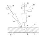
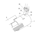
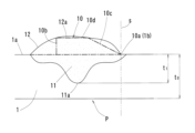
1a 外面
10 突部
11 溶け込み部
20 溶接装置
21 第1の溶接材料(第1の溶接ワイヤ)
22 第2の溶接材料(第2の溶接ワイヤ)
P 管体
Claims (3)
- 管軸方向一端の挿し口(1)に半径方向外側に突出する突部(10)を備えた管体(P)の製造方法において、
第1の溶接材料(21)及び第2の溶接材料(22)を用い、前記第1の溶接材料(21)に通電させて発生したアークにより前記挿し口(1)の外面(1a)に溶融部(W)を形成し、前記溶融部(W)が硬化する前に前記第2の溶接材料(22)を非通電で前記溶融部(W)に宛がうことにより、前記突部(10)を溶接肉盛りで形成する管体の製造方法。 - 前記第1の溶接材料(21)及び前記第2の溶接材料(22)による溶接金属と前記挿し口(1)の母材とが融合した溶け込み部(11)を、前記挿し口(1)の外面(1a)から前記挿し口(1)の母材の肉厚(t0)に対して10%以上80%未満の深さに形成する請求項1に記載の管体の製造方法。
- 管軸方向一端の挿し口(1)に半径方向外側に突出する突部(10)を備え遠心力鋳造により製造された管体(P)において、
前記挿し口(1)に設けられ前記挿し口(1)の外面(1a)よりも半径方向外側に突出する溶接金属からなる突部(10)と、
前記突部(10)の内径側に位置し前記挿し口(1)の母材と溶接金属とが融合した溶け込み部(11)と、を備え、
前記溶け込み部(11)は、前記挿し口(1)の外面(1a)から前記挿し口(1)の母材の肉厚(t0)に対して10%以上80%未満の深さに至っており、
前記突部(10)は、耐震管継手部の抜け止め機能を発揮するようにその外面に円筒部(10d)が成形されている管体。
Priority Applications (1)
| Application Number | Priority Date | Filing Date | Title |
|---|---|---|---|
| JP2020105893A JP7565713B2 (ja) | 2020-06-19 | 2020-06-19 | 挿し口を有する管体及び挿し口を有する管体の製造方法 |
Applications Claiming Priority (1)
| Application Number | Priority Date | Filing Date | Title |
|---|---|---|---|
| JP2020105893A JP7565713B2 (ja) | 2020-06-19 | 2020-06-19 | 挿し口を有する管体及び挿し口を有する管体の製造方法 |
Publications (2)
| Publication Number | Publication Date |
|---|---|
| JP2022000310A JP2022000310A (ja) | 2022-01-04 |
| JP7565713B2 true JP7565713B2 (ja) | 2024-10-11 |
Family
ID=79241793
Family Applications (1)
| Application Number | Title | Priority Date | Filing Date |
|---|---|---|---|
| JP2020105893A Active JP7565713B2 (ja) | 2020-06-19 | 2020-06-19 | 挿し口を有する管体及び挿し口を有する管体の製造方法 |
Country Status (1)
| Country | Link |
|---|---|
| JP (1) | JP7565713B2 (ja) |
Citations (1)
| Publication number | Priority date | Publication date | Assignee | Title |
|---|---|---|---|---|
| JP2008185114A (ja) | 2007-01-30 | 2008-08-14 | Kubota Corp | 管の挿口突部の形成方法 |
Family Cites Families (3)
| Publication number | Priority date | Publication date | Assignee | Title |
|---|---|---|---|---|
| JPS62124077A (ja) * | 1985-11-21 | 1987-06-05 | Agency Of Ind Science & Technol | 溶加ワイヤ式磁気制御mig溶接法 |
| JPH09150265A (ja) * | 1995-11-27 | 1997-06-10 | Kubota Corp | 自動アーク溶接装置 |
| JP3233049B2 (ja) * | 1996-11-21 | 2001-11-26 | 住友金属工業株式会社 | スパイラル鋼管の製造方法 |
-
2020
- 2020-06-19 JP JP2020105893A patent/JP7565713B2/ja active Active
Patent Citations (1)
| Publication number | Priority date | Publication date | Assignee | Title |
|---|---|---|---|---|
| JP2008185114A (ja) | 2007-01-30 | 2008-08-14 | Kubota Corp | 管の挿口突部の形成方法 |
Also Published As
| Publication number | Publication date |
|---|---|
| JP2022000310A (ja) | 2022-01-04 |
Similar Documents
| Publication | Publication Date | Title |
|---|---|---|
| JP2020040103A (ja) | コイル線のレーザ溶接方法 | |
| JP5526567B2 (ja) | 溶接接合部材 | |
| US6791052B1 (en) | Method for resistance welding a tube to a member | |
| JP2024144868A (ja) | 挿し口突部の製造方法および挿し口突部を備えた管体 | |
| WO2014034225A1 (ja) | プロペラシャフトの製造方法及びプロペラシャフト | |
| WO2014024033A1 (en) | Method of forming a pipe joint and pipe joint | |
| JP2022000310A (ja) | 挿し口を有する管体及び挿し口を有する管体の製造方法 | |
| CN112846461A (zh) | 一种多边形结构件的焊接方法 | |
| WO2019003394A1 (ja) | 樹脂製チューブ部材、樹脂製チューブ部材の製造方法、樹脂製管継手及び、樹脂製配管 | |
| JPH01218774A (ja) | バット溶接法及びそれに用いる押さえ型 | |
| JP3891695B2 (ja) | 棒状部材の接合方法 | |
| JP6662210B2 (ja) | 接合方法 | |
| JPS6355399B2 (ja) | ||
| JPH0256990B2 (ja) | ||
| JP2018513021A (ja) | 溶接されたリングを作成する方法 | |
| JP2002219583A (ja) | 摩擦攪拌接合における終端部処理方法および終端部処理された摩擦攪拌接合体 | |
| JP2024093539A (ja) | 接合用工具及び接合部材 | |
| JPS61226187A (ja) | 高合金鋼クラツド鋼管の製造方法 | |
| JP2023008547A (ja) | 治具、配管融着構造、及び配管融着方法 | |
| JPH04294893A (ja) | 溶接用フラックス入りワイヤの接続方法 | |
| JP2647472B2 (ja) | 薄肉管の継手製造方法 | |
| JPS6316874A (ja) | 鋼管のバツト溶接方法 | |
| RU2355540C2 (ru) | Способ сварки кольцевых стыков труб | |
| JP3233722B2 (ja) | 融着継手の製造方法 | |
| JP2007160387A (ja) | 棒鋼の接合工法 |
Legal Events
| Date | Code | Title | Description |
|---|---|---|---|
| A621 | Written request for application examination |
Free format text: JAPANESE INTERMEDIATE CODE: A621 Effective date: 20230227 |
|
| A131 | Notification of reasons for refusal |
Free format text: JAPANESE INTERMEDIATE CODE: A131 Effective date: 20231219 |
|
| A977 | Report on retrieval |
Free format text: JAPANESE INTERMEDIATE CODE: A971007 Effective date: 20231221 |
|
| A521 | Request for written amendment filed |
Free format text: JAPANESE INTERMEDIATE CODE: A523 Effective date: 20240219 |
|
| A131 | Notification of reasons for refusal |
Free format text: JAPANESE INTERMEDIATE CODE: A131 Effective date: 20240604 |
|
| A521 | Request for written amendment filed |
Free format text: JAPANESE INTERMEDIATE CODE: A523 Effective date: 20240805 |
|
| TRDD | Decision of grant or rejection written | ||
| A01 | Written decision to grant a patent or to grant a registration (utility model) |
Free format text: JAPANESE INTERMEDIATE CODE: A01 Effective date: 20240903 |
|
| A61 | First payment of annual fees (during grant procedure) |
Free format text: JAPANESE INTERMEDIATE CODE: A61 Effective date: 20241001 |
|
| R150 | Certificate of patent or registration of utility model |
Ref document number: 7565713 Country of ref document: JP Free format text: JAPANESE INTERMEDIATE CODE: R150 |