JP7565713B2 - Tube with insertion port and method for manufacturing tube with insertion port - Google Patents
Tube with insertion port and method for manufacturing tube with insertion port Download PDFInfo
- Publication number
- JP7565713B2 JP7565713B2 JP2020105893A JP2020105893A JP7565713B2 JP 7565713 B2 JP7565713 B2 JP 7565713B2 JP 2020105893 A JP2020105893 A JP 2020105893A JP 2020105893 A JP2020105893 A JP 2020105893A JP 7565713 B2 JP7565713 B2 JP 7565713B2
- Authority
- JP
- Japan
- Prior art keywords
- insertion port
- welding
- protrusion
- tube
- base material
- Prior art date
- Legal status (The legal status is an assumption and is not a legal conclusion. Google has not performed a legal analysis and makes no representation as to the accuracy of the status listed.)
- Active
Links
- 238000003780 insertion Methods 0.000 title claims description 66
- 230000037431 insertion Effects 0.000 title claims description 66
- 238000000034 method Methods 0.000 title claims description 15
- 238000004519 manufacturing process Methods 0.000 title claims description 9
- 238000003466 welding Methods 0.000 claims description 104
- 239000000463 material Substances 0.000 claims description 60
- 239000002184 metal Substances 0.000 claims description 27
- 230000035515 penetration Effects 0.000 claims description 18
- 238000009750 centrifugal casting Methods 0.000 claims description 5
- 239000011324 bead Substances 0.000 description 7
- 229910002555 FeNi Inorganic materials 0.000 description 5
- 238000012545 processing Methods 0.000 description 3
- 230000008602 contraction Effects 0.000 description 2
- 238000000151 deposition Methods 0.000 description 2
- 230000004907 flux Effects 0.000 description 2
- 230000004927 fusion Effects 0.000 description 2
- 238000002844 melting Methods 0.000 description 2
- 230000008018 melting Effects 0.000 description 2
- 230000002265 prevention Effects 0.000 description 2
- 238000000926 separation method Methods 0.000 description 2
- 239000007787 solid Substances 0.000 description 2
- 230000015572 biosynthetic process Effects 0.000 description 1
- 238000005266 casting Methods 0.000 description 1
- 238000010276 construction Methods 0.000 description 1
- 238000007796 conventional method Methods 0.000 description 1
- 238000005520 cutting process Methods 0.000 description 1
- 230000003247 decreasing effect Effects 0.000 description 1
- 230000000694 effects Effects 0.000 description 1
- 238000002474 experimental method Methods 0.000 description 1
- 239000012530 fluid Substances 0.000 description 1
- 230000005484 gravity Effects 0.000 description 1
- 238000010438 heat treatment Methods 0.000 description 1
- 239000000155 melt Substances 0.000 description 1
- 239000007769 metal material Substances 0.000 description 1
- 238000012986 modification Methods 0.000 description 1
- 230000004048 modification Effects 0.000 description 1
- 230000002093 peripheral effect Effects 0.000 description 1
- 238000007493 shaping process Methods 0.000 description 1
Images


Landscapes
- Butt Welding And Welding Of Specific Article (AREA)
Description
この発明は、挿し口を有する管体、及び、挿し口を有する管体の製造方法に関するものである。 This invention relates to a tube having an insertion port and a method for manufacturing a tube having an insertion port.
従来から、各種の流体を移送するために使用される管体として、その継ぎ手部に伸縮機能と離脱防止機能を備えたものがある。この種の継ぎ手構造は耐震管継手とも呼ばれ、例えば、図5に示すように、管体Pの挿し口1の外周に設けた突部10が、対向する別の管体Pの受口2の内周溝に嵌め込んだロックリング4に係合して、抜け止め機能を発揮するようになっている。また、挿し口1の突部10が、受口2の内面の奥端面3とロックリング4との間で所定距離だけ(図中の区間A及び区間Bに相当)移動することで、管軸方向への伸縮が可能となっている。また、挿し口1と受口2との間にゴム輪5を備えたことで、挿し口1の外面1aと受口2の内面2aとの間の液密性も確保されている。挿し口1を有する管体Pとして、例えば、特許文献1に記載されたものがある。
Conventionally, there are pipes used to transport various fluids, and their joints have an expansion and contraction function and a separation prevention function. This type of joint structure is also called an earthquake-resistant pipe joint. For example, as shown in FIG. 5, a
挿し口の外周の突部は、管体の外周に金属製のリングを嵌めて、そのリングを管体の外面に溶接等で固定するのが一般的である。リングを管体の外面に溶接して挿し口の突部を形成する手法として、例えば、特許文献2に記載されたものがある。また、溶接金属を肉盛りすることによって挿し口の突部を形成する手法として、例えば、特許文献3に記載されたものがある。
The projection on the outer periphery of the insertion port is generally formed by fitting a metal ring around the outer periphery of the tube and then fixing the ring to the outer surface of the tube by welding or the like. For example,
しかし、特許文献2のように、リングの溶接で突部を形成する手法は、リングの嵌め込みに手間がかかる上、溶接作業とその溶接前後の処理に多くの時間が必要であるという問題がある。また、特許文献3のように、溶接金属の肉盛りで突部を形成する手法は、ビードの溶接量が多いため、溶接に時間を要するという問題がある。また、溶接を伴う手法の場合、溶接箇所の品質を維持することが難しく、施工不良によって母材である管体に対して過度に深く溶け込みを生じさせて、材料を無駄にしたり管体を破断しやすくしてしまう場合もある。
However, the method of forming the protrusion by welding the ring, as in
そこで、この発明の課題は、挿し口の外周の突部を溶接により容易に且つ精度よく形成することである。 Therefore, the objective of this invention is to easily and accurately form the protrusion on the outer periphery of the insertion port by welding.
上記の課題を解決するために、この発明は、管軸方向一端の挿し口に半径方向外側に突出する突部を備えた管体の製造方法において、第1の溶接材料と第2の溶接材料を用い、前記第1の溶接材料に通電させて発生したアークにより前記挿し口の外面に溶融部を形成し、前記溶融部が硬化する前に前記第2の溶接材料を非通電で前記溶融部に宛がうことにより前記突部を溶接肉盛りで形成する管体の製造方法を採用した。 In order to solve the above problems, this invention employs a method for manufacturing a tube having a protrusion that protrudes radially outward from an insertion port at one end in the tube axial direction, in which a first welding material and a second welding material are used, an arc is generated by passing an electric current through the first welding material to form a molten part on the outer surface of the insertion port, and before the molten part hardens, the second welding material is applied to the molten part without passing an electric current through it, thereby forming the protrusion by weld build-up.
このとき、前記第1の溶接材料及び前記第2の溶接材料による溶接金属と前記挿し口の母材とが融合した溶け込み部を、前記挿し口の外面から前記挿し口の母材の肉厚に対して10%以上80%未満の深さに形成する構成を採用することができる。 In this case, a configuration can be adopted in which the penetration portion where the weld metal of the first welding material and the second welding material fuses with the base material of the insertion port is formed to a depth from the outer surface of the insertion port that is 10% or more and less than 80% of the thickness of the base material of the insertion port.
また、上記の課題を解決するために、この発明は、管軸方向一端の挿し口に半径方向外側に突出する突部を備えた管体において、前記挿し口に設けられ前記挿し口の外面よりも半径方向外側に突出する溶接金属からなる突部と、前記突部の内径側に位置し前記挿し口の母材と溶接金属とが融合した溶け込み部と、を備え、前記溶け込み部は、前記挿し口の外面から前記挿し口の母材の肉厚に対して10%以上80%未満の深さに至っている管体を採用した。 In order to solve the above problems, the present invention employs a tube body having a protrusion that protrudes radially outward from an insertion port at one end in the tube axial direction, the protrusion being made of weld metal and protruding radially outward beyond the outer surface of the insertion port, and a fusion portion located on the inner diameter side of the protrusion and in which the base material of the insertion port and the weld metal are fused, the fusion portion extending from the outer surface of the insertion port to a depth of 10% or more but less than 80% of the thickness of the base material of the insertion port.
この発明は、挿し口の外周の突部を溶接により容易に且つ精度よく形成することができる。 This invention allows the protrusions on the outer periphery of the insertion port to be formed easily and precisely by welding.
この発明の一実施形態を図1~図4に基づいて説明する。この実施形態は、管軸方向一端の挿し口1に半径方向外側に突出する突部10を備えた管体P、及び、その管体Pの製造方法である。管体Pの主たる構成は、従来例の説明で利用した図5の通りであるのでその説明を省略し、以下、この発明の特徴である挿し口1の突部10の構成を中心に説明する。
One embodiment of the present invention will be described with reference to Figures 1 to 4. This embodiment is a tube P having a
管体Pは、管軸方向一端に挿し口1を、管軸方向他端に受口2を備えるものであり、挿し口1には、挿し口1の外面1aよりも半径方向外側に突出する突部10を、管軸周り全周に亘って連続的に備えている(図5参照)。この突部10は、溶接金属によって形成された溶接肉盛りで構成されている。すなわち、挿し口1を構成する金属製の母材に対して溶接肉盛り(溶接ビード)が形成されており、その溶接金属により形成された部分が突部10となっている。ここで、突部10は溶接金属から構成されているとしているが、突部10を構成する素材に溶接金属内に溶融した挿し口1の母材が含まれていることを排除するものではない。
The pipe body P has an
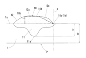
また、図1及び図4に示すように、突部10の内径側には、挿し口1の外面1aよりも内径側に深さt1だけ入り込んで、挿し口1の母材と溶接金属とが融合した溶け込み部11を備えている。溶け込み部11の最大の深さt1は、挿し口1の外面1aから挿し口1の母材の肉厚t0に対して10%~80%の深さに至っている。
As shown in Figures 1 and 4, the inner diameter side of the
挿し口1の突部10を形成する前の管体Pは、遠心鋳造法によって製造される。遠心鋳造法は、円筒状の金型を駆動力によって回転するローラ上に載せて、金型を軸周りに回転させながら、その金型内に金属の溶湯を注入し、その溶湯を硬化させることで管体Pを形成する。金型には、注入された溶湯が外部に漏れ出ることを防止する堰が設けられている。硬化後の管体Pは金型の外に引き抜かれる。管体Pは、所定の熱処理等によって材質を整えられ、その後、挿し口1の突部10の加工が行われる。
The tube P before the
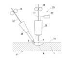
突部10の加工を行う溶接装置20を、図2及び図3に示す。この溶接装置20は、コールドタンデム溶接を行うための装置であり、アーク溶接用の第1の溶接材料21を通電状態で供給するアーク溶接用トーチ23と、非通電状態の第2の溶接材料22を供給する溶接材料供給装置24とを備えている。アーク溶接用トーチ23と溶接材料供給装置24とは、連結部材25で連結されて所定の間隔に維持されている。この所定の間隔は、調整により増減することもできる。
The
アーク溶接用トーチ23は、送り出し装置28によって第1の溶接材料21を母材である挿し口1の外面1aの溶接位置aに送り出す。第1の溶接材料21は電流を流す電極として機能し、電源27から供給された溶接電流が第1の溶接材料21に通電することで、母材との間にアークを発生させる。第1の溶接材料21としては、周知の溶接ワイヤ、例えば、FeNi φ0.8~1.6mmを用いることができる。このほかにも、第1の溶接材料21として、周知のソリッドワイヤ、フラックスワイヤ、各種溶接棒、帯状電極等、各種の素材を用いることができる。この実施形態では、第1の溶接材料21として溶接ワイヤを用いているので、以下これを第1の溶接ワイヤ21と称する。
The
溶接材料供給装置24は、送り出し装置26によって第2の溶接材料22を、通電することなく、母材である挿し口1の外面の溶接位置bに向かって送り出す。第2の溶接材料22としては、例えば、FeNi φ0.8~1.6mmを用いることができる。このほかにも、第2の溶接材料22として、周知のソリッドワイヤ、フラックスワイヤ、各種溶接棒、帯状電極等、各種の素材を用いることができる。この実施形態では、第2の溶接材料22として溶接ワイヤを用いているので、以下これを第2の溶接ワイヤ22と称する。
The welding
つぎに、この実施形態に係る管体Pの製造方法に関し、特に、挿し口1の突部10の形成方法について説明する。
Next, we will explain the manufacturing method of the tube body P according to this embodiment, in particular the method of forming the
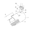
図3に示すように、管体Pは、把持装置Hによって保持されて、図中に矢印Rで示すように、管軸周りに回転することができる。この管体Pの回転により、連結部材25で連結された状態のアーク溶接用トーチ23及び溶接材料供給装置24が、母材である管体Pの挿し口1に対して管周に沿って相対移動する。この相対移動の際に、溶接材料供給装置24は、管体Pの回転方向Rに沿って、アーク溶接用トーチ23よりも前方に配置されることが望ましい。すなわち、第1の溶接ワイヤ21の位置aは、挿し口1の外面1a上での溶接箇所の進行方向(管体Pの回転方向Rと反対の方向)に対して、第2の溶接ワイヤ22の位置bよりも前方であることが望ましい。
3, the tube P is held by a gripping device H and can rotate around the tube axis as shown by the arrow R in the figure. This rotation of the tube P causes the
このように、第1の溶接ワイヤ21と第2の溶接ワイヤ22を用い、第1の溶接ワイヤ21に通電させて発生したアークにより、図2に示すように、挿し口1の外面1aに溶融部Wを形成し、その溶融部Wが硬化する前に、第2の溶接ワイヤ22を非通電の状態で溶融部Wに宛がう。これにより、挿し口1の外面1aに、外径側へ突出する突部10が溶接肉盛り(溶接ビード)によって形成される。このとき、第2の溶接ワイヤ22は非通電の状態であるが、第1の溶接ワイヤ21のアークによって生じた溶融部Wに宛がわれることで熱を帯び、その第2の溶接ワイヤ22の金属が溶け出して、溶接金属として溶融部Wに供給されている。
In this way, the
また、同時に、第1の溶接ワイヤ21及び第2の溶接ワイヤ22による溶接金属と、挿し口1の母材とが融合した溶け込み部11が、挿し口1の外面1aから挿し口1の母材の肉厚t0に対して10%以上80%未満の深さに形成される。ここで、溶け込み部11の最大の深さt1の母材の肉厚t0に対する比率は、20%以上60%未満であればさらに好ましい。この深さの比率が低すぎると溶け込み不足によって突部10の強度が不足する可能性があり、また、この深さの比率が大きすぎると母材が貫通してしまう可能性があるからである。このような深さの比率を設定するのに際し、上記のコールドタンデム溶接の手法が最適であることを、発明者らは発見した。
At the same time, the weld metal from the
すなわち、挿し口1の突部10を溶接肉盛りで形成するに際し、コールドタンデム溶接を用いたことにより、単位時間当たりの溶接金属の供給量が増加し、単位時間当たりの溶融量(溶接速度)の増大を図ることができる。また、非通電の第2の溶接ワイヤ22を溶融部Wに添えることにより、溶融部Wにおける金属素材の溶融プールの冷却を図ることができ、溶け込み深さの低減と、溶接金属のたれ防止を可能としている。これらの効果により、従来のリングを用いた溶接手法と同等の速度で、所望の突部10のビード形状を得ることができた。
In other words, by using cold tandem welding when forming the
突部10の完成形状は、図1に鎖線で示すように、中央のフラットな円筒部10dを挟んで、図中右側の挿し口1の先端1b側は、その先端1bに向かって徐々に縮径するテーパ面10cである。また、後端側は、挿し口1の外面1aとの間で段部10bを構成している。これにより、突部10の断面は、管軸を通る任意の断面において台形状となっている。
As shown by the dashed line in Figure 1, the completed shape of the
溶接直後の突部10の形状は、図1に実線で示すように、完成形状の突部10よりもやや大きいビード表面12を有する断面形状であるので、これを削って完成形状に成形していく。なお、図1では、突部10の先端10aが挿し口1の先端1bに一致しているので、図中の符号Sで示すラインで管体Pを切断する構成となっているが、この切断は突部10の先端10aと挿し口1の先端1bとの位置関係に応じて行えばよく、必須の工程ではない。完成形状への突部10の成形は、高周波グラインダや旋盤加工を組み合わせて行うことができる。
The shape of the
なお、図1では、管軸周りに2回転させる間に全周の突部10を仕上げる2層溶接を行ったことにより、溶接直後の突部10の形状は、ビード表面12に2つの山部12a,12bを有する形態である。また、溶け込み部11も同様に、溶け込み深さが周囲よりもやや深い谷部11a,11bを2つ有する形態である。このような2層溶接、あるいは、3層以上の溶接を行うことで、突部10の成形はより容易に且つより精度のよいものとなる。ただし、図4に示すように、管軸周りに1回転させる間に全周の突部10を仕上げる1層溶接を行うことも可能である。1層溶接の場合、溶接直後の突部10の形状は、ビード表面12に1つの山部12aを有し、溶け込み部11に、溶け込み深さが周囲よりもやや深い谷部11aを1つ有する形態である。
In FIG. 1, two-layer welding is performed to finish the entire circumference of the
実験では、第1の溶接ワイヤ21及び第2の溶接ワイヤ22として、FeNi φ1.6mmを用い、管厚6mmの管体Pの周面での回転速度25mm/sに対して、第1の溶接ワイヤ21の供給量を900cm/min、第2の溶接ワイヤ22の供給量を500cm/minとして、2層溶接で溶接金属量を突部10全体で160gとし、管厚に対する溶け込み深さの比率約33%を確保して良好な結果を得た。また、1層溶接では、同じくFeNi φ1.6mmを用い、管体Pの周面での回転速度12.5mm/sに対して、第1の溶接ワイヤ21の供給量を900cm/min、第2の溶接ワイヤ22の供給量を600cm/minとして、溶接金属量を突部10全体で170gとし、管厚に対する溶け込み深さの比率約60%を確保して良好な結果を得た。この点、従来のリングを用いた突部10の形成方法では、FeNi φ1.2mmを用いた場合、管体Pの周面での回転速度25mm/sに対して、溶接ワイヤの供給量を920cm/minとした場合、溶接金属量は突部10全体で59gであった。すなわち、この発明において、コールドタンデム溶接を用いたことにより、単位時間当たりの溶融量(溶接速度)の増大が実現していることが理解できる。
In the experiment, FeNi φ1.6 mm was used as the
この実施形態では、挿し口1の突部10を形成する前の管体Pを遠心鋳造法によって製造したが、突部10を形成する前の管体Pの製造方法は、遠心鋳造法以外、例えば、重力で鋳型内に溶湯を注ぎ込んで凝固させる置注鋳造法等であってもよい。また、突部10を形成する挿し口1が、溶接に対応した金属製のものであれば、種々の管体Pにこの発明を適用できる。
In this embodiment, the tube P before the
1 挿し口
1a 外面
10 突部
11 溶け込み部
20 溶接装置
21 第1の溶接材料(第1の溶接ワイヤ)
22 第2の溶接材料(第2の溶接ワイヤ)
P 管体
1
22 Second welding material (second welding wire)
P Tube
Claims (3)
第1の溶接材料(21)及び第2の溶接材料(22)を用い、前記第1の溶接材料(21)に通電させて発生したアークにより前記挿し口(1)の外面(1a)に溶融部(W)を形成し、前記溶融部(W)が硬化する前に前記第2の溶接材料(22)を非通電で前記溶融部(W)に宛がうことにより、前記突部(10)を溶接肉盛りで形成する管体の製造方法。 A method for manufacturing a tube (P) having a protrusion (10) protruding radially outward from an insertion port (1) at one end in the tube axial direction, comprising the steps of:
The method for manufacturing a tube includes using a first welding material (21) and a second welding material (22), forming a molten portion (W) on the outer surface (1a) of the insertion hole (1) by an arc generated by passing an electric current through the first welding material (21), and applying the second welding material (22) to the molten portion (W) without passing an electric current through it before the molten portion (W) hardens, thereby forming the protrusion (10) by weld build-up.
前記挿し口(1)に設けられ前記挿し口(1)の外面(1a)よりも半径方向外側に突出する溶接金属からなる突部(10)と、
前記突部(10)の内径側に位置し前記挿し口(1)の母材と溶接金属とが融合した溶け込み部(11)と、を備え、
前記溶け込み部(11)は、前記挿し口(1)の外面(1a)から前記挿し口(1)の母材の肉厚(t0)に対して10%以上80%未満の深さに至っており、
前記突部(10)は、耐震管継手部の抜け止め機能を発揮するようにその外面に円筒部(10d)が成形されている管体。 A tube body (P) manufactured by centrifugal casting, the tube body (P) having a protrusion (10) protruding radially outward from an insertion port (1) at one end in the tube axial direction,
a protrusion (10) made of weld metal provided in the insertion port (1) and protruding radially outward from an outer surface (1a) of the insertion port (1);
a penetration portion (11) located on the inner diameter side of the protrusion (10) and in which the base material of the insertion port (1) and the weld metal are fused together,
The penetration portion (11) extends from the outer surface (1a) of the insertion port (1) to a depth of 10% or more and less than 80% of the wall thickness (t0) of the base material of the insertion port (1);
The protrusion (10) is a pipe having a cylindrical portion (10d) formed on its outer surface so as to exert a function of preventing the earthquake-resistant pipe joint from coming loose.
Priority Applications (1)
| Application Number | Priority Date | Filing Date | Title |
|---|---|---|---|
| JP2020105893A JP7565713B2 (en) | 2020-06-19 | 2020-06-19 | Tube with insertion port and method for manufacturing tube with insertion port |
Applications Claiming Priority (1)
| Application Number | Priority Date | Filing Date | Title |
|---|---|---|---|
| JP2020105893A JP7565713B2 (en) | 2020-06-19 | 2020-06-19 | Tube with insertion port and method for manufacturing tube with insertion port |
Publications (2)
| Publication Number | Publication Date |
|---|---|
| JP2022000310A JP2022000310A (en) | 2022-01-04 |
| JP7565713B2 true JP7565713B2 (en) | 2024-10-11 |
Family
ID=79241793
Family Applications (1)
| Application Number | Title | Priority Date | Filing Date |
|---|---|---|---|
| JP2020105893A Active JP7565713B2 (en) | 2020-06-19 | 2020-06-19 | Tube with insertion port and method for manufacturing tube with insertion port |
Country Status (1)
| Country | Link |
|---|---|
| JP (1) | JP7565713B2 (en) |
Citations (1)
| Publication number | Priority date | Publication date | Assignee | Title |
|---|---|---|---|---|
| JP2008185114A (en) | 2007-01-30 | 2008-08-14 | Kubota Corp | Method for forming tube insertion protrusion |
Family Cites Families (3)
| Publication number | Priority date | Publication date | Assignee | Title |
|---|---|---|---|---|
| JPS62124077A (en) * | 1985-11-21 | 1987-06-05 | Agency Of Ind Science & Technol | Filter wire type magnetic control mig welding method |
| JPH09150265A (en) * | 1995-11-27 | 1997-06-10 | Kubota Corp | Automatic arc welding equipment |
| JP3233049B2 (en) * | 1996-11-21 | 2001-11-26 | 住友金属工業株式会社 | Spiral steel pipe manufacturing method |
-
2020
- 2020-06-19 JP JP2020105893A patent/JP7565713B2/en active Active
Patent Citations (1)
| Publication number | Priority date | Publication date | Assignee | Title |
|---|---|---|---|---|
| JP2008185114A (en) | 2007-01-30 | 2008-08-14 | Kubota Corp | Method for forming tube insertion protrusion |
Also Published As
| Publication number | Publication date |
|---|---|
| JP2022000310A (en) | 2022-01-04 |
Similar Documents
| Publication | Publication Date | Title |
|---|---|---|
| JP2020040103A (en) | Laser welding method for coil wire | |
| JP6505364B2 (en) | Friction stir welding method | |
| JP7565713B2 (en) | Tube with insertion port and method for manufacturing tube with insertion port | |
| JP2010207850A (en) | Welding joining member and welding joining method | |
| US6791052B1 (en) | Method for resistance welding a tube to a member | |
| EP0916443A1 (en) | Rotating member and rotating shaft member, fixing roller, cylindrical member, and cylinder of image forming apparatus, cylindrical member welding method, rotating shaft member manufacturing method, and method of manufacturing developing sleeve of image forming apparatus | |
| JP2024144868A (en) | Manufacturing method of insertion protrusion and tube body equipped with insertion protrusion | |
| WO2014024033A1 (en) | Method of forming a pipe joint and pipe joint | |
| CN112846461A (en) | Welding method of polygonal structural member | |
| JP6382455B2 (en) | How to create a welded ring | |
| WO2019003394A1 (en) | Resinous tube member, method for manufacturing resinous tube member, resinous tube fitting, and resinous piping | |
| JPH01218774A (en) | Butt welding method and press die used therefor | |
| CN104507704A (en) | Method for manufacturing rear axle, and rear axle | |
| JP3891695B2 (en) | Method for joining rod-shaped members | |
| JP4264775B2 (en) | Dissimilar metal joining method | |
| JP6662210B2 (en) | Joining method | |
| JPS6355399B2 (en) | ||
| JP2002219583A (en) | Terminal treatment method in frictional stirring joining and frictional stirring jointed body with the terminal treated | |
| JP2561360B2 (en) | Welding wire and manufacturing method thereof | |
| JPS61126971A (en) | Tig welding method of pipe material | |
| JP2024093539A (en) | Joining tools and joining materials | |
| JP2023008547A (en) | Jig, pipe fusion structure, and pipe fusion method | |
| JPH04294893A (en) | Method for connecting flux cored wire for welding | |
| JP2647472B2 (en) | Manufacturing method for thin-walled pipe joints | |
| JPS6316874A (en) | Butt welding method for steel pipe |
Legal Events
| Date | Code | Title | Description |
|---|---|---|---|
| A621 | Written request for application examination |
Free format text: JAPANESE INTERMEDIATE CODE: A621 Effective date: 20230227 |
|
| A131 | Notification of reasons for refusal |
Free format text: JAPANESE INTERMEDIATE CODE: A131 Effective date: 20231219 |
|
| A977 | Report on retrieval |
Free format text: JAPANESE INTERMEDIATE CODE: A971007 Effective date: 20231221 |
|
| A521 | Request for written amendment filed |
Free format text: JAPANESE INTERMEDIATE CODE: A523 Effective date: 20240219 |
|
| A131 | Notification of reasons for refusal |
Free format text: JAPANESE INTERMEDIATE CODE: A131 Effective date: 20240604 |
|
| A521 | Request for written amendment filed |
Free format text: JAPANESE INTERMEDIATE CODE: A523 Effective date: 20240805 |
|
| TRDD | Decision of grant or rejection written | ||
| A01 | Written decision to grant a patent or to grant a registration (utility model) |
Free format text: JAPANESE INTERMEDIATE CODE: A01 Effective date: 20240903 |
|
| A61 | First payment of annual fees (during grant procedure) |
Free format text: JAPANESE INTERMEDIATE CODE: A61 Effective date: 20241001 |
|
| R150 | Certificate of patent or registration of utility model |
Ref document number: 7565713 Country of ref document: JP Free format text: JAPANESE INTERMEDIATE CODE: R150 |