JP7561572B2 - Disk-type processing device - Google Patents
Disk-type processing device Download PDFInfo
- Publication number
- JP7561572B2 JP7561572B2 JP2020179744A JP2020179744A JP7561572B2 JP 7561572 B2 JP7561572 B2 JP 7561572B2 JP 2020179744 A JP2020179744 A JP 2020179744A JP 2020179744 A JP2020179744 A JP 2020179744A JP 7561572 B2 JP7561572 B2 JP 7561572B2
- Authority
- JP
- Japan
- Prior art keywords
- disk
- casing
- opening
- wall portion
- processing device
- Prior art date
- Legal status (The legal status is an assumption and is not a legal conclusion. Google has not performed a legal analysis and makes no representation as to the accuracy of the status listed.)
- Active
Links
Images


Classifications
-
- F—MECHANICAL ENGINEERING; LIGHTING; HEATING; WEAPONS; BLASTING
- F26—DRYING
- F26B—DRYING SOLID MATERIALS OR OBJECTS BY REMOVING LIQUID THEREFROM
- F26B15/00—Machines or apparatus for drying objects with progressive movement; Machines or apparatus with progressive movement for drying batches of material in compact form
- F26B15/10—Machines or apparatus for drying objects with progressive movement; Machines or apparatus with progressive movement for drying batches of material in compact form with movement in a path composed of one or more straight lines, e.g. compound, the movement being in alternate horizontal and vertical directions
- F26B15/12—Machines or apparatus for drying objects with progressive movement; Machines or apparatus with progressive movement for drying batches of material in compact form with movement in a path composed of one or more straight lines, e.g. compound, the movement being in alternate horizontal and vertical directions the lines being all horizontal or slightly inclined
- F26B15/14—Machines or apparatus for drying objects with progressive movement; Machines or apparatus with progressive movement for drying batches of material in compact form with movement in a path composed of one or more straight lines, e.g. compound, the movement being in alternate horizontal and vertical directions the lines being all horizontal or slightly inclined the objects or batches of materials being carried by trays or racks or receptacles, which may be connected to endless chains or belts
-
- B—PERFORMING OPERATIONS; TRANSPORTING
- B01—PHYSICAL OR CHEMICAL PROCESSES OR APPARATUS IN GENERAL
- B01F—MIXING, e.g. DISSOLVING, EMULSIFYING OR DISPERSING
- B01F27/00—Mixers with rotary stirring devices in fixed receptacles; Kneaders
- B01F27/60—Mixers with rotary stirring devices in fixed receptacles; Kneaders with stirrers rotating about a horizontal or inclined axis
- B01F27/73—Mixers with rotary stirring devices in fixed receptacles; Kneaders with stirrers rotating about a horizontal or inclined axis with rotary discs
-
- B—PERFORMING OPERATIONS; TRANSPORTING
- B01—PHYSICAL OR CHEMICAL PROCESSES OR APPARATUS IN GENERAL
- B01F—MIXING, e.g. DISSOLVING, EMULSIFYING OR DISPERSING
- B01F35/00—Accessories for mixers; Auxiliary operations or auxiliary devices; Parts or details of general application
- B01F35/75—Discharge mechanisms
- B01F35/751—Discharging by opening a gate, e.g. using discharge paddles
-
- B—PERFORMING OPERATIONS; TRANSPORTING
- B01—PHYSICAL OR CHEMICAL PROCESSES OR APPARATUS IN GENERAL
- B01F—MIXING, e.g. DISSOLVING, EMULSIFYING OR DISPERSING
- B01F35/00—Accessories for mixers; Auxiliary operations or auxiliary devices; Parts or details of general application
- B01F35/75—Discharge mechanisms
- B01F35/754—Discharge mechanisms characterised by the means for discharging the components from the mixer
- B01F35/7547—Discharge mechanisms characterised by the means for discharging the components from the mixer using valves, gates, orifices or openings
-
- B—PERFORMING OPERATIONS; TRANSPORTING
- B01—PHYSICAL OR CHEMICAL PROCESSES OR APPARATUS IN GENERAL
- B01F—MIXING, e.g. DISSOLVING, EMULSIFYING OR DISPERSING
- B01F35/00—Accessories for mixers; Auxiliary operations or auxiliary devices; Parts or details of general application
- B01F35/90—Heating or cooling systems
- B01F35/92—Heating or cooling systems for heating the outside of the receptacle, e.g. heated jackets or burners
-
- F—MECHANICAL ENGINEERING; LIGHTING; HEATING; WEAPONS; BLASTING
- F25—REFRIGERATION OR COOLING; COMBINED HEATING AND REFRIGERATION SYSTEMS; HEAT PUMP SYSTEMS; MANUFACTURE OR STORAGE OF ICE; LIQUEFACTION SOLIDIFICATION OF GASES
- F25D—REFRIGERATORS; COLD ROOMS; ICE-BOXES; COOLING OR FREEZING APPARATUS NOT OTHERWISE PROVIDED FOR
- F25D13/00—Stationary devices, e.g. cold-rooms
- F25D13/06—Stationary devices, e.g. cold-rooms with conveyors carrying articles to be cooled through the cooling space
-
- F—MECHANICAL ENGINEERING; LIGHTING; HEATING; WEAPONS; BLASTING
- F25—REFRIGERATION OR COOLING; COMBINED HEATING AND REFRIGERATION SYSTEMS; HEAT PUMP SYSTEMS; MANUFACTURE OR STORAGE OF ICE; LIQUEFACTION SOLIDIFICATION OF GASES
- F25D—REFRIGERATORS; COLD ROOMS; ICE-BOXES; COOLING OR FREEZING APPARATUS NOT OTHERWISE PROVIDED FOR
- F25D23/00—General constructional features
-
- F—MECHANICAL ENGINEERING; LIGHTING; HEATING; WEAPONS; BLASTING
- F26—DRYING
- F26B—DRYING SOLID MATERIALS OR OBJECTS BY REMOVING LIQUID THEREFROM
- F26B17/00—Machines or apparatus for drying materials in loose, plastic, or fluidised form, e.g. granules, staple fibres, with progressive movement
- F26B17/28—Machines or apparatus for drying materials in loose, plastic, or fluidised form, e.g. granules, staple fibres, with progressive movement with movement performed by rollers or discs with material passing over or between them, e.g. suction drum, sieve, the axis of rotation being in fixed position
- F26B17/282—Machines or apparatus for drying materials in loose, plastic, or fluidised form, e.g. granules, staple fibres, with progressive movement with movement performed by rollers or discs with material passing over or between them, e.g. suction drum, sieve, the axis of rotation being in fixed position the materials adhering to, and being dried on, the surface of rotating discs with or without scraping devices
-
- F—MECHANICAL ENGINEERING; LIGHTING; HEATING; WEAPONS; BLASTING
- F26—DRYING
- F26B—DRYING SOLID MATERIALS OR OBJECTS BY REMOVING LIQUID THEREFROM
- F26B25/00—Details of general application not covered by group F26B21/00 or F26B23/00
- F26B25/001—Handling, e.g. loading or unloading arrangements
- F26B25/003—Handling, e.g. loading or unloading arrangements for articles
-
- F—MECHANICAL ENGINEERING; LIGHTING; HEATING; WEAPONS; BLASTING
- F26—DRYING
- F26B—DRYING SOLID MATERIALS OR OBJECTS BY REMOVING LIQUID THEREFROM
- F26B25/00—Details of general application not covered by group F26B21/00 or F26B23/00
- F26B25/04—Agitating, stirring, or scraping devices
-
- F—MECHANICAL ENGINEERING; LIGHTING; HEATING; WEAPONS; BLASTING
- F26—DRYING
- F26B—DRYING SOLID MATERIALS OR OBJECTS BY REMOVING LIQUID THEREFROM
- F26B25/00—Details of general application not covered by group F26B21/00 or F26B23/00
- F26B25/06—Chambers, containers, or receptacles
- F26B25/08—Parts thereof
- F26B25/12—Walls or sides; Doors
-
- F—MECHANICAL ENGINEERING; LIGHTING; HEATING; WEAPONS; BLASTING
- F26—DRYING
- F26B—DRYING SOLID MATERIALS OR OBJECTS BY REMOVING LIQUID THEREFROM
- F26B25/00—Details of general application not covered by group F26B21/00 or F26B23/00
- F26B25/06—Chambers, containers, or receptacles
- F26B25/14—Chambers, containers, receptacles of simple construction
- F26B25/18—Chambers, containers, receptacles of simple construction mainly open, e.g. dish, tray, pan, rack
-
- F—MECHANICAL ENGINEERING; LIGHTING; HEATING; WEAPONS; BLASTING
- F26—DRYING
- F26B—DRYING SOLID MATERIALS OR OBJECTS BY REMOVING LIQUID THEREFROM
- F26B3/00—Drying solid materials or objects by processes involving the application of heat
- F26B3/18—Drying solid materials or objects by processes involving the application of heat by conduction, i.e. the heat is conveyed from the heat source, e.g. gas flame, to the materials or objects to be dried by direct contact
- F26B3/20—Drying solid materials or objects by processes involving the application of heat by conduction, i.e. the heat is conveyed from the heat source, e.g. gas flame, to the materials or objects to be dried by direct contact the heat source being a heated surface, e.g. a moving belt or conveyor
-
- F—MECHANICAL ENGINEERING; LIGHTING; HEATING; WEAPONS; BLASTING
- F26—DRYING
- F26B—DRYING SOLID MATERIALS OR OBJECTS BY REMOVING LIQUID THEREFROM
- F26B3/00—Drying solid materials or objects by processes involving the application of heat
- F26B3/18—Drying solid materials or objects by processes involving the application of heat by conduction, i.e. the heat is conveyed from the heat source, e.g. gas flame, to the materials or objects to be dried by direct contact
- F26B3/22—Drying solid materials or objects by processes involving the application of heat by conduction, i.e. the heat is conveyed from the heat source, e.g. gas flame, to the materials or objects to be dried by direct contact the heat source and the materials or objects to be dried being in relative motion, e.g. of vibration
- F26B3/24—Drying solid materials or objects by processes involving the application of heat by conduction, i.e. the heat is conveyed from the heat source, e.g. gas flame, to the materials or objects to be dried by direct contact the heat source and the materials or objects to be dried being in relative motion, e.g. of vibration the movement being rotation
-
- B—PERFORMING OPERATIONS; TRANSPORTING
- B01—PHYSICAL OR CHEMICAL PROCESSES OR APPARATUS IN GENERAL
- B01F—MIXING, e.g. DISSOLVING, EMULSIFYING OR DISPERSING
- B01F35/00—Accessories for mixers; Auxiliary operations or auxiliary devices; Parts or details of general application
- B01F35/90—Heating or cooling systems
- B01F2035/99—Heating
Landscapes
- Engineering & Computer Science (AREA)
- Mechanical Engineering (AREA)
- General Engineering & Computer Science (AREA)
- Chemical & Material Sciences (AREA)
- Chemical Kinetics & Catalysis (AREA)
- Life Sciences & Earth Sciences (AREA)
- Microbiology (AREA)
- Combustion & Propulsion (AREA)
- Physics & Mathematics (AREA)
- Thermal Sciences (AREA)
- Drying Of Solid Materials (AREA)
Description
この発明は、ケーシング内において処理対象物を連続的に乾燥または冷却することが可能なディスク型処理装置に関する。 This invention relates to a disk-type processing device that can continuously dry or cool the object to be processed within a casing.
周知のように、例えば、一般工業製品、合成樹脂等の化学製品、飼料、食品や薬品等、幅広い産業分野で、処理対象物を効率的に乾燥処理させるためにディスクドライヤ等のディスク型処理装置が広く使用されている。 As is well known, disk-type processing devices such as disk dryers are widely used to efficiently dry materials in a wide range of industrial fields, including general industrial products, chemical products such as synthetic resins, feed, food, and pharmaceuticals.
ディスク型処理装置は、例えば、両端部に配置された側壁部と、側壁部の間を接続する周壁部とを有するドラム等のケーシングと、このケーシングの内部空間に配置された回転軸と回転軸に形成され、軸線方向に間隔をあけて配置された複数のディスクを備えた構成のものが開示されている(例えば、特許文献1、特許文献2参照。)。
Disclosed disk-type processing devices include, for example, a casing such as a drum having side walls at both ends and a peripheral wall connecting the side walls, a rotating shaft disposed in the internal space of the casing, and multiple disks formed on the rotating shaft and spaced apart in the axial direction (see, for example,
このようなディスク型処理装置は、各ディスクの内部やケーシングの周壁部等に形成されたジャケットやディスクの内部に水蒸気や温水等の加熱媒体または冷却水等の冷却媒体を流通させて、処理対象物を加熱または冷却可能とされている。 Such disk-type processing equipment can heat or cool the object to be processed by circulating a heating medium such as water vapor or hot water or a cooling medium such as cooling water inside each disk or in a jacket formed on the peripheral wall of the casing, etc.
また、各ディスクの周囲には、ディスクの回転方向に対して所定の傾きをもって設けられた送り羽根と傾きのない平羽根が設けられていて、送り羽根によって、軸線方向に沿ってケーシング内で処理対象物を移送するように構成されている。
このような構成により、ディスク型処理装置は、処理対象物を効率的に乾燥することが可能とされている。
In addition, around each disk, there are provided feed blades that are inclined at a predetermined angle relative to the direction of rotation of the disk, and flat blades that are not inclined, and the feed blades are configured to transport the material to be processed within the casing along the axial direction.
With such a configuration, the disk-type processing apparatus is capable of efficiently drying the object to be processed.
しかしながら、ファインケミカル品等の処理対象物を乾燥または冷却させる場合には、処理対象物と異なる種類の異物の影響があると商品価値が低下することから、異なる処理対象物が混入するのを最大限抑制することが必要である。 However, when drying or cooling processing objects such as fine chemicals, the presence of foreign matter of a different type from the processing object reduces the commercial value, so it is necessary to prevent contamination by different processing objects as much as possible.
そこで、ケーシング内の洗浄性、清掃性を向上することが必要となるが、ケーシング内を充分に清掃、洗浄するのは容易ではなく、ケーシング内において処理対象物に異物が混入するのを確実に防止するための技術が望まれる。 Therefore, it is necessary to improve the washability and cleanability of the inside of the casing, but it is not easy to thoroughly clean the inside of the casing, and technology is needed to reliably prevent foreign matter from getting mixed into the material being treated inside the casing.
この発明は、このような事情を考慮してなされたものであって、処理対象物を開口部から容易かつ効率的に排出させることが可能とされ、ケーシング内に処理対象物が残留するのを抑制することが可能なディスク型処理装置を提供することを目的とする。 This invention was made in consideration of these circumstances, and aims to provide a disk-type processing device that can easily and efficiently discharge the object to be processed from the opening and prevent the object from remaining in the casing.
上記課題を解決するために、この発明は以下の手段を提案している。
請求項1に記載の発明は、一方側に配置された第1端壁部と、他方側に配置された第2端壁部と、前記一方側において前記第1端壁部と接続されるとともに前記他方側において前記第2端壁部と接続され、上部に開口部が形成された周壁部と、を有するケーシング本体と、前記ケーシング本体の開口部を開閉可能とされ前記ケーシング本体と協働してケーシングを構成する開閉蓋部材と、前記第1端壁部と前記第2端壁部に支持され前記ケーシング内に配置されるとともに、軸線の周りに回転可能とされた回転軸と、前記回転軸の周囲に前記軸線方向に間隔をあけて形成され、前記回転軸とともに回転可能とされた複数のディスク部材と、前記ディスク部材に配置され、前記ケーシング内において処理対象物を前記軸線方向に沿って移送する処理対象物移送手段と、前記ケーシング本体を、前記開口部が下方を向くように傾動可能とされたケーシング傾動機構と、を備えていることを特徴とする。
In order to solve the above problems, the present invention proposes the following means.
The invention described in
この発明に係るディスク型処理装置によれば、第1端壁部と、第2端壁部と、一方側において第1端壁部と接続され他方側において第2端壁部と接続され上部に開口部が形成された周壁部と、を有するケーシング本体と、このケーシング本体の開口部を開閉する開閉蓋部材と、ケーシング本体を傾動させるケーシング傾動機構と、を備えていて、このケーシング傾動機構により、開閉蓋部材が外されたケーシング本体を、開口部が下方を向くように傾動させることが可能とされているので、開口部を下側に向けることにより、ケーシング本体内の処理対象物を開口部から容易かつ効率的に排出させることができる。
その結果、ケーシング内に処理対象物が残留するのを抑制することができる。
また、ディスク型処理装置のケーシング内の清掃性、洗浄性を向上させることができる。
The disk-type processing device of the present invention comprises a casing body having a first end wall portion, a second end wall portion, and a peripheral wall portion connected to the first end wall portion on one side and connected to the second end wall portion on the other side, with an opening formed at the top, an opening/closing cover member for opening and closing the opening of the casing body, and a casing tilting mechanism for tilting the casing body.This casing tilting mechanism makes it possible to tilt the casing body from which the opening/closing cover member has been removed so that the opening faces downward, so that by facing the opening downward, the material to be processed inside the casing body can be easily and efficiently discharged from the opening.
As a result, it is possible to prevent the material to be treated from remaining inside the casing.
Furthermore, the cleaning and washing properties of the inside of the casing of the disk-type processing device can be improved.
また、ケーシング内には、回転軸と、回転軸の周囲に軸線方向に間隔をあけて形成されたディスク部材が配置され、処理対象物移送手段により処理対象物を移送しながら乾燥または冷却させるので、処理対象物を効率的かつ連続的に処理することができる。 In addition, a rotating shaft and disk members formed around the rotating shaft at intervals in the axial direction are arranged inside the casing, and the treatment object is dried or cooled while being transported by the treatment object transport means, so that the treatment object can be efficiently and continuously processed.
ここで、ケーシング本体を、開口部が下方を向くように傾動するとは、周壁部の地面に対する傾斜角度が、処理対象物の安息角よりも大きくなることを意味している。 Here, tilting the casing body so that the opening faces downward means that the angle of inclination of the peripheral wall with respect to the ground becomes greater than the angle of repose of the material to be treated.
請求項2に記載の発明は、請求項1に記載のディスク型処理装置であって、前記開閉蓋部材を開閉可能に移動させる蓋部材開閉機構を備えていることを特徴とする。
The invention described in claim 2 is the disk-type processing device described in
この発明に係るディスク型処理装置によれば、開閉蓋部材を開閉可能に移動させる蓋部材開閉機構を備えているので、人手によることなく、開閉蓋部材を容易かつ効率的に開閉することができる。 The disk-type processing device according to the present invention is equipped with a lid member opening/closing mechanism that moves the opening/closing lid member so that it can be opened and closed, so that the opening/closing lid member can be opened and closed easily and efficiently without manual intervention.
請求項3に記載の発明は、請求項1又は2に記載のディスク型処理装置であって、前記ケーシング傾動機構は、前記回転軸と同軸の軸線の周りに回動させて前記ケーシング本体を傾動させることを特徴とする。
The invention described in claim 3 is the disk-type processing device described in
この発明に係るディスク型処理装置によれば、ケーシング傾動機構が、回転軸と同軸の軸線の周りに回動させてケーシング本体を傾動させるので、ケーシング本体を傾動させる際のスペースが大きくなるのを抑制することができる。
その結果、ディスク型処理装置の大型化を抑制して小型化することができる。
According to the disk-type processing device of the present invention, the casing tilting mechanism tilts the casing body by rotating it around an axis line coaxial with the rotation axis, thereby preventing the space required to tilt the casing body from becoming large.
As a result, the disk type processing device can be made smaller by preventing it from becoming larger.
請求項4に記載の発明は、請求項1~3のいずれか一項に記載のディスク型処理装置であって、前記ケーシング本体には、処理が完了した処理対象物を排出する製品排出口が形成されていて、前記製品排出口を開閉可能な排出口蓋部材を備えていることを特徴とする。
The invention described in claim 4 is the disk-type processing device described in any one of
この発明に係るディスク型処理装置によれば、ケーシング本体に処理が完了した処理対象物を排出する製品排出口が形成されていて、製品排出口を開閉可能な排出口蓋部材を備えているので、排出口蓋部材を外して製品排出口を開放することにより、ケーシング本体を容易に傾動させることができる。 According to the disk-type processing device of the present invention, a product discharge port is formed in the casing body for discharging the processed object, and a discharge port cover member is provided that can open and close the product discharge port. Therefore, the casing body can be easily tilted by removing the discharge port cover member to open the product discharge port.
請求項5に記載の発明は、請求項4に記載のディスク型処理装置であって、前記排出口蓋部材と連結された排出口開閉機構を備え、前記排出口開閉機構は、前記排出口蓋部材を前記製品排出口から離間可能に構成されていることを特徴とする。 The invention described in claim 5 is the disk-type processing device described in claim 4, characterized in that it includes a discharge port opening/closing mechanism connected to the discharge port cover member, and the discharge port opening/closing mechanism is configured to be able to separate the discharge port cover member from the product discharge port.
この発明に係るディスク型処理装置によれば、排出口蓋部材と連結された排出口開閉機構を備えていて、排出口開閉機構は、排出口蓋部材を製品排出口から離間可能に構成されているので、ケーシング本体から排出口蓋部材を容易かつ効率的に外してケーシング本体を傾動可能な状態とすることができる。 The disk-type processing device according to the present invention is equipped with a discharge port opening/closing mechanism connected to the discharge port lid member, and the discharge port opening/closing mechanism is configured to be able to separate the discharge port lid member from the product discharge port, so that the discharge port lid member can be easily and efficiently removed from the casing body, allowing the casing body to be tilted.
請求項6に記載の発明は、請求項1~5のいずれか一項に記載のディスク型処理装置であって、前記ケーシング本体は、プレートコイル(登録商標)を用いて形成されていることを特徴とする。
The invention described in claim 6 is a disk-type processing device described in any one of
この発明に係るディスク型処理装置によれば、周壁部がプレートコイル(登録商標)を用いて形成されているので、ケーシング本体を軽量に形成することが可能となり、ケーシング本体を容易に傾動させることができる。 The disk-type processing device according to the present invention has a peripheral wall formed using a plate coil (registered trademark), which allows the casing body to be made lightweight and allows the casing body to be tilted easily.
ここで、プレートコイルとは、例えば、少なくとも一枚の波状板部材を用いることにより、波状板部材を構成している凹凸によって流体が流通可能な流路が形成された板状熱交換器をいう。 Here, a plate coil refers to a plate-shaped heat exchanger that uses, for example, at least one corrugated plate member, and in which a flow path through which a fluid can flow is formed by the unevenness that constitutes the corrugated plate member.
請求項7に記載の発明は、請求項1~6のいずれか一項に記載のディスク型処理装置であって、前記ケーシング傾動機構は、前記ケーシング本体を傾動するための駆動源を備えていることを特徴とする。
The invention described in
この発明に係るディスク型処理装置によれば、ケーシング傾動機構が、ケーシング本体を傾動するための駆動源を備えているので、ケーシング本体を効率的に傾動させることが可能となり、ケーシング内の処理対象物を効率的に排出することができる。 According to the disk-type processing device of this invention, the casing tilting mechanism is equipped with a drive source for tilting the casing body, so that the casing body can be tilted efficiently, and the material to be processed inside the casing can be efficiently discharged.
この発明に係るディスク型処理装置によれば、処理対象物を開口部から容易かつ効率的に排出させることが可能とされ、ケーシング内に処理対象物が残留するのを抑制することができる。 The disk-type processing device of this invention makes it possible to easily and efficiently discharge the object to be processed from the opening, and prevents the object from remaining in the casing.
以下、図1~図15を参照して、本発明の一実施形態に係るディスク型処理装置について説明する。
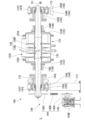
図1、図2は、本発明の第1実施形態に係るディスク型処理装置の概略構成を説明する図であり、図1は側面から見た図であり、図2は平面図である。また、図3は、ディスク型処理装置の概略構成を説明する一方側から見た斜視図であり、図4は、他方側から見た斜視図である。また、図5は処理装置本体の概略構成を説明する平面視した部分断面図であり、図6は側面視した部分断面図である。また、図7Aはケーシングの概略構成を説明する斜視図であり、図7Bはケーシング本体を説明する斜視図であり、図7Cは開閉蓋部材の側面図である。
A disk-type processing device according to an embodiment of the present invention will be described below with reference to FIGS.
Fig. 1 and Fig. 2 are diagrams for explaining the schematic configuration of a disk-type processing device according to a first embodiment of the present invention, with Fig. 1 being a side view and Fig. 2 being a plan view. Fig. 3 is a perspective view from one side explaining the schematic configuration of the disk-type processing device, and Fig. 4 is a perspective view from the other side. Fig. 5 is a partial cross-sectional view in plan view explaining the schematic configuration of the processing device main body, and Fig. 6 is a partial cross-sectional view in side view. Fig. 7A is a perspective view explaining the schematic configuration of the casing, Fig. 7B is a perspective view explaining the casing main body, and Fig. 7C is a side view of the opening and closing cover member.
図において、符号100はディスク型処理装置を、符号110は処理装置本体を、符号120はケーシングを、符号122Aは開口部を、符号126は開閉蓋部材を、符号130はディスク回転体を、符号132は回転軸を、符号135はディスク集合体を、符号136はディスク部材を、符号140は回転軸駆動部を、符号150は蓋部材開閉機構を、符号160はケーシング傾動機構を、符号170は排出口開閉機構を示している。
In the figure,
第1実施形態に係るディスク型処理装置100は、図1~図4に示すように、例えば、処理装置本体110と、蓋部材開閉機構150と、ケーシング傾動機構160と、排出口開閉機構170と、を備えている。
As shown in Figures 1 to 4, the disk-
処理装置本体110は、図1~図6に示すように、例えば、支持架台112と、支持架台112の上部に配置されたケーシング120と、ケーシング120内に配置されたディスク回転体130と、ディスク回転体130を回転駆動させる回転軸駆動部140と、を備えている。
この実施形態において、支持架台112は、例えば、架台ベース111の上面に立設されている。
そして、処理装置本体110は、投入された処理対象物(不図示)を、連続的に処理(例えば、乾燥または冷却)して製品(処理物)とするように構成されている。
As shown in Figures 1 to 6, the processing device
In this embodiment, the
The processing device
処理装置本体110が処理する処理対象物は、任意に設定することが可能であるが、例えば、ファインセラミックス、半導体材料、薬品、機能性樹脂等のファインケミカルが挙げられる。
The object to be processed by the processing device
ケーシング120は、図1~図5、図7Aに示すように、例えば、ケーシング本体122と、開閉蓋部材126と、排出口蓋部材128(図2、図4、図5参照)と、を備えている。
As shown in Figures 1 to 5 and 7A, the
ケーシング本体122は、図5、図6、図7A、図7Bに示すように、例えば、軸線O1方向における一方側Lに配置された第1端壁部123Lと、他方側Rに配置された第2端壁部123Rと、第1端壁部123Lと第2端壁部123Rとを接続する周壁部125と、天板部材125Aと、を備えている。
As shown in Figures 5, 6, 7A, and 7B, the
第1端壁部123Lは、図5、図6、図7A、図7Bに示すように、例えば、軸線O1に沿って見たときに、下部が略U字形に形成されるとともに、U字形の上端部同士が接続された外形形状とされ、ケーシング本体122の内方から一方側Lに向かって突出して形成されている。
また、第1端壁部123Lには、軸線O1を中心とし、一方側Lから他方側Rに貫通する貫通穴(第2端壁部123Rの123Hを参照)が形成されている。
また、第1端壁部123Lには、周囲にフランジ部が形成されている。
As shown in Figures 5, 6, 7A, and 7B, when viewed along the axis O1, the first
Further, the first
Additionally, a flange portion is formed around the periphery of the first
第2端壁部123Rは、図5、図6、図7A、図7Bに示すように、例えば、軸線O1に沿って見たときに、第1端壁部123Lと同様に、下部が略U字形に形成されるとともに、U字形の上端部同士が接続された外形形状とされ、ケーシング本体122の内方から他方側Rに向かって突出して形成されている。
また、第2端壁部123Rには、図7A、図7Bに示すように、軸線O1を中心とし、一方側Lから他方側Rに貫通する貫通穴123Hが形成されている。
また、第2端壁部123Rには、周囲にフランジ部が形成されている。
As shown in Figures 5, 6, 7A, and 7B, when viewed, for example, along the axis O1, the second
Further, in the second
Further, a flange portion is formed around the periphery of the second
周壁部125は、図7A、図7Bに示すように、例えば、平面視略矩形に形成されるとともに、軸線O1に沿って見たときに略U字形に形成されている。
具体的には、軸線O1に沿って見たときに、例えば、軸線O1より下側が略半円の円弧状壁部とされ、その円弧状壁部の両側の端部から立上り壁部が鉛直上方に伸びる構成とされている。なお、周壁部125を軸線に沿って見たときの形状については任意に設定することができる。
また、周壁部125の一方側Lと他方側Rの端部には、ケーシング本体122の内方から外方に向かって伸びるフランジ部が形成されている。
As shown in FIGS. 7A and 7B, the
Specifically, when viewed along the axis O1, for example, the lower side of the axis O1 is an approximately semicircular arc-shaped wall portion, and rising wall portions extend vertically upward from both ends of the arc-shaped wall portion. Note that the shape of the
Furthermore, flange portions extending from the inside to the outside of the
周壁部125を形成する材料は任意に設定することが可能であるが、この実施形態において、周壁部125は、例えば、プレートコイル(登録商標)(不図示)を用いて形成されている。
具体的には、例えば、周壁部125の円弧状壁部とその円弧状壁部を軸線O1に沿って見たときの円弧状壁部の両端から上方に伸びる立ち上がり壁部の一部(例えば、処理対象物と接触可能な軸線O1よりも少し上側までの範囲)に、プレートコイルが適用されている。なお、プレートコイルを適用して形成する範囲は任意に設定することが可能である。
The material for forming the
Specifically, for example, the plate coil is applied to the arc-shaped wall portion of the
その結果、周壁部125の内部にはジャケットが形成され、蒸気や温水、冷却水等の温度調整用媒体を流通させることにより、加温又は冷却に適用することが可能となる。
なお、プレートコイル(不図示)を用いることなく、周壁部125を複数枚(例えば、2重)構造とすることでジャケットを形成してもよいし、温度調整用のジャケットを設けない構成としてもよい。
As a result, a jacket is formed inside the
It should be noted that a jacket may be formed by forming the
ここで、プレートコイルとは、例えば、少なくとも一枚の波状板部材と他の板状部材の互いの面同士を対向させて接続することにより、波状板部材を構成する凹凸によって温度調整用媒体が流通可能な流路が形成された板状熱交換器をいう。
なお、プレートコイルの構成は任意に設定することが可能であり、プレートコイルが波形状とは別に湾曲等の形状を有していてもよいし、波状板部材同士、波状板部材と平板状部材を組み合わせてもよいし、3枚以上の板部材の面同士を対向させて接続してもよい。
Here, a plate coil refers to a plate-shaped heat exchanger in which, for example, at least one corrugated plate member and another plate member are connected with their faces facing each other, and a flow path through which a temperature-regulating medium can flow is formed by the unevenness that constitutes the corrugated plate member.
The configuration of the plate coil can be set as desired; the plate coil may have a curved shape or other shape in addition to a wave shape, or may combine wave-shaped plate members together or a wave-shaped plate member with a flat plate member, or may connect the faces of three or more plate members facing each other.
天板部材125Aは、図5、図7A、図7Bに示すように、例えば、周壁部125の一方側Lの上端部と他方側Rの上端部に配置されていて、それぞれ周壁部125を構成するU字形状において対向する立ち上がり壁部の上端部同士を接続する構成されている。
As shown in Figures 5, 7A, and 7B, the
また、一方側Lに配置される天板部材125Aは、図6、図7Bに示すように、側面から見たときに略チャネル状に形成されていて、一方側Lにフランジ部が形成されている。そして、天板部材125Aが周壁部125と接続されたときに、周壁部125のフランジ部と協働して、第1端壁部123Lのフランジ部と対応するようになっている。
そして、周壁部125と天板部材125Aが協働して形成したフランジ部には、第1端壁部123Lが連結可能とされている。
また、一方側Lに配置される天板部材125Aの他方側Rには、立ち上がり壁部が形成されていて、開口部122Aの一方側Lの周縁部を形成する構成とされている。
6 and 7B, the
The first
Further, a rising wall portion is formed on the other side R of the
また、他方側Rに配置される天板部材125Aは、図6、図7Bに示すように、側面から見たときに略チャネル状に形成されていて、他方側Rにはフランジ部が形成され、一方側Lに立ち上がり壁部が形成されている。
他方側Rに配置される天板部材125Aは、軸線O1方向における反対向きに配置される点以外は一方側Lに配置される天板部材125Aと同様であるので、説明を省略する。
In addition, the
The
これにより、ケーシング本体122の上部には、周壁部125の対向する立ち上がり壁部同士と、一方側Lと他方側Rの天板部材125Aで囲まれ、上方に開口する開口部122Aが形成される。
また、開口部122Aは、例えば、平面視略矩形に形成されている。
天板部材125Aを形成する材料は任意に設定することが可能である。
As a result, an
Moreover, the
The material for forming the
また、ケーシング本体122には、図7Bに示すように、例えば、周壁部125の背面側Bの立上り壁部に製品排出口125Dが形成されている。
製品排出口125Dは、図7Bに示すように、例えば、上下方向に長尺な矩形に形成されている。
また、製品排出口125Dには、図7Bに示すように、排出口蓋部材128が配置可能とされている。
As shown in FIG. 7B, the
As shown in FIG. 7B, the
Further, as shown in FIG. 7B, a discharge
開閉蓋部材126は、図7Cに示すように、例えば、開口部122Aと対応して略矩形の枠状に形成されたフランジ部126Aと、フランジ部126Aの上面に接続され上方に突出する略矩形箱状に形成された蓋部材本体126Bと、を備えている。
As shown in FIG. 7C, the opening/
また、フランジ部126Aの下方には、ケーシング本体122の開口部122Aを閉じたときに、開口部122Aを介してケーシング本体122内に向かって伸び、ケーシング本体122の内部空間に収容される重なり部壁部126Eが形成されている。
また、フランジ部126Aの下面は、開口部122Aの周縁部を閉塞する封止面126Fとされている。
In addition, below the
The lower surface of the
また、開閉蓋部材126には、図7Cに示すように、内部に下方に向かって伸びるへら状部材126Cが配置されていて、処理対象物がディスク回転体130に付着するのを抑制可能とされている。
また、開閉蓋部材126には、例えば、上部に処理対象物投入口126Dが形成されるとともに、必要に応じて点検用窓等を任意に設定することができる。
In addition, as shown in FIG. 7C, a spatula-shaped
Furthermore, the opening/
排出口蓋部材128は、例えば、製品排出口125Dを閉塞可能な略矩形枠状の封止部(不図示)を有している。
また、排出口蓋部材128は、図7Bに示すように、矢印T1で示すように、製品排出口125Dに対して離間、接近することにより、製品排出口125Dを開閉することが可能とされている。
また、排出口蓋部材128が製品排出口125Dに配置されたときに、封止部(不図示)によって製品排出口125Dを閉塞することにより、製品排出口125Dは封止されるようになっている。
The discharge
As shown in FIG. 7B, the
Furthermore, when the
そして、製品排出口125Dは封止されることで、処理装置本体110が処理対象部を処理(例えば、乾燥、冷却)することが可能となる。また、ケーシング120内から処理対象物が漏れ出たり、ケーシング120内に異物の混入するのを抑制可能に構成されている。
The
また、排出口蓋部材128は、内部に、処理された処理対象物の排出量を調整する排出量調整機構(不図示)が配置されている。
排出量調整機構(不図示)は、例えば、仕切板(不図示)を備えていて、この仕切板を上部のハンドル(図4、図15参照)128Aによって上下方向に移動可能に構成されている。
The discharge
The discharge amount adjustment mechanism (not shown) includes, for example, a partition plate (not shown), and this partition plate is configured to be movable in the vertical direction by an upper handle (see Figs. 4 and 15) 128A.
そして、仕切板(不図示)を上下方向に移動させて、仕切板を超える製品(処理物)の量を調整することにより、ケーシング120内に滞留する処理対象物及び製品の滞留時間を調整するとともに、製品排出口125Dから排出される製品の量が調整されるように構成されている。
The partition plate (not shown) is moved vertically to adjust the amount of product (processed material) that exceeds the partition plate, thereby adjusting the residence time of the processing object and product remaining within the
次に、図5、図6、図8~図10を参照して、ディスク回転体130について説明する。
図8は、第1実施形態に係るディスク型処理装置のディスク回転体の概略構成を説明する側面から見た図であり、図9は、ディスク回転体の概略構成を説明する軸線に沿って見た図である。また、図10は、ディスク回転体の概略構成を説明する羽根部材の配置の一例を示す展開図である。
Next, the
Fig. 8 is a side view illustrating the schematic configuration of the disk rotor of the disk-type processing device according to the first embodiment, Fig. 9 is a view along the axis illustrating the schematic configuration of the disk rotor, and Fig. 10 is a development view showing an example of the arrangement of the blade members illustrating the schematic configuration of the disk rotor.
ディスク回転体130は、例えば、回転軸132と、ディスク集合体135と、羽根部材137と、回転軸駆動部140と、を備えている。
図において、符号137は羽根部材を、符号137Aは送り羽根部材(処理対象物移送手段)を、符号137Bは平羽根部材を示している。
The
In the figure,
回転軸132は、例えば、略水平方向(横方向)に配置された回転軸線(軸線)O1に沿った多段円筒状に形成されている。
そして、回転軸132は、一方側Lと他方側Rを後述する軸受部材147によって支持され、回転軸線O1の周りに回転可能とされている。
The
The
また、回転軸132の内方には、例えば、軸線O1における一方側Lに熱媒体を流入させる流入口(不図示)が形成され、他方側Rに熱媒体を排出させる排出口(不図示)が形成されている。
また、回転軸132は、軸線O1方向における中央側にディスク集合体135が配置されている。
Further, on the inside of the
Further, the
ディスク集合体135は、軸線O1に沿った方向に間隔をあけて配置された複数のディスク部材136を備えている。
そして、ディスク集合体135は、図5、図6に示すように、ケーシング120の内部空間に配置されている。
The
The
ディスク部材136は、図5、図6、図8に示すように、例えば、一対のディスク板136L、136Rの軸線O1方向において対向する端面同士を接合することにより構成されている。
また、ディスク部材136は、中心部に軸線O1を中心とする円形の貫通穴が開口するドーナツ状とされ、この貫通穴に回転軸132が挿入されて回転軸132と接続されている。
As shown in FIGS. 5, 6 and 8, the
The
具体的には、ディスク部材136は、例えば、軸線O1方向における一方側L側に膨出する第1ディスク板136Lの他方側Rの端面と、他方側Rに膨出する第2ディスク板136Rの一方側Lの端面を溶接等によって接合することにより略そろばん玉状に形成されている。
Specifically, the
また、ディスク部材136には、例えば、内部に熱媒体が流通可能な熱媒体流通空間(不図示)が形成されている。
その結果、回転軸132の流入口(不図示)から供給された熱媒体が一方側Lのディスク部材136から他方側Rのディスク部材136に向かって順次流通する。
そして、回転軸132の排出口(不図示)から排出されるようになっている。
Further, the
As a result, the heat medium supplied from an inlet (not shown) of the
The liquid is then discharged from a discharge port (not shown) of the
また、ディスク部材136を形成する材料は任意に設定することが可能であるが、例えば、ステンレス鋼により形成することが好適である。
また、ディスク集合体135を構成するディスク部材136の数は任意に設定することが可能である。
Furthermore, the material from which the
Furthermore, the number of
羽根部材137は、図8~図10に示すように、例えば、送り羽根部材(処理対象物移送手段)137Aと、平羽根部材137Bと、を備え、ディスク部材136の外周縁に配置されている。
As shown in Figures 8 to 10, the
送り羽根部材(処理対象物移送手段)137Aは、図8~図10に示すように、例えば、回転軸132の回転軸線O1に対して、移送条件と対応させた所定のリード角となるように配置された平板により形成されていて、ステーによってディスク部材136の周縁部に連結されている。
As shown in Figures 8 to 10, the feed vane member (means for transferring material to be processed) 137A is formed, for example, from a flat plate arranged so as to have a predetermined lead angle corresponding to the transfer conditions with respect to the rotation axis O1 of the
平羽根部材137Bは、図8~図10に示すように、例えば、回転軸132の回転軸線O1と平行な平面により形成されていて、ステーによってディスク部材136の周縁部に連結されている。
そして、平羽根部材137Bは、回転軸132が回転すると、処理対象部とを軸線O1方向に移動させることなく攪拌するように構成されている。
As shown in FIGS. 8 to 10, the
The
この実施形態では、羽根部材137は、図10に示すように、例えば、ディスク部材136の周縁部に180°の間隔をあけて配置されている。
具体的には、送り羽根部材(処理対象物移送手段)137Aと平羽根部材137Bが各ディスク部材136に一つずつ配置されている。
In this embodiment, the
Specifically, a feed blade member (processing object transporting means) 137A and a
また、隣接するディスク部材136では、送り羽根部材(処理対象物移送手段)137A、平羽根部材137Bが90°間隔で交互に配置されている。
なお、羽根部材137の配置、位置、数については、例えば、処理対象物の種類や回転軸132の回転速度等に基づいて任意に設定することが可能である。
In addition, in
The arrangement, position and number of the
そして、回転軸132が回転すると、図9に示すように、ディスク回転体130に配置された送り羽根137Aが矢印S1で示す方向に回転する。
その結果、ケーシング120内の処理対象物は、図8、図10に示すように、ケーシング120内において一方側Lから他方側Rに向かって矢印S2方向に移送されるように構成されている。
When the
As a result, the object to be treated within the
回転軸駆動部140は、図5、図6に示すように、例えば、回転軸132を回転駆動する駆動モータ142Mと、駆動伝達装置144と、軸受部材147と、シール部材148と、を備えている。
As shown in Figures 5 and 6, the rotating
駆動伝達装置144は、図5、図6に示すように、例えば、駆動モータ142Mの駆動軸に連結された減速機145と減速機145の出力軸に配置されたスプロケット146Aと、回転軸132の一方側Lの端部に配置されたスプロケット146Cと、スプロケット146Aとスプロケット146Cとを接続するチェーン146Bとを備えている。
そして、駆動モータ142Mが発生した回転駆動力は、減速機145、スプロケット146A、チェーン146B、スプロケット146Cを介して回転軸132に伝達され、回転軸132を回転軸線O1の周りに回転するように構成されている。
As shown in Figures 5 and 6, the
The rotational driving force generated by the
軸受部材147は、図5、図6に示すように、例えば、回転軸132の一方側Lを回転可能に支持する第1軸受部材147Lと、他方側Rを回転可能に支持する第2軸受部材147Rと、を備えている。
As shown in Figures 5 and 6, the bearing
第1軸受部材147Lは、図5、図6に示すように、回転軸132の一方側Lが挿入され、後述するケーシング傾動筒163L内に嵌挿されている。
そして、第1傾動ピローブロック164Lを介して、一方側Lの支持架台112の上部に配置されている。
As shown in FIGS. 5 and 6, one side L of the
It is disposed above the
第2軸受部材147Rは、図5、図6に示すように、回転軸132の他方側Rが挿入され、後述するケーシング傾動筒163R内に嵌挿されている。
そして、第2傾動ピローブロック164Rを介して、他方側Rの支持架台112の上部に配置されている。
このように構成されることで、回転軸132は、左右の支持架台112に対して回転することが可能となる。
As shown in FIGS. 5 and 6, the other side R of the
It is disposed above the
With this configuration, the
シール部材148は、図5、図6に示すように、例えば、ケーシング120を挟んで一方側Lに配置される第1シール部材148Lと、他方側Rに配置される第2シール部材148Rと、を備えている。
具体的には、第1シール部材148Lは、例えば、第1端壁部123Lの一方側Lの外面に連結され、内周側に形成されたシール穴に、回転軸132が回転可能に挿入されている。そして、第1端壁部123Lの貫通穴123Hを介してケーシング120内と外部とを密封する構成とされている。
As shown in Figures 5 and 6, the
Specifically, the
また、第2シール部材148Rは、例えば、第2端壁部123Rの他方側Rの外面に連結され、内周側に内周側に形成されたシール穴に、回転軸132が回転可能に挿入されている。
そして、第2端壁部123Rの貫通穴123Hを介してケーシング120内と外部とを密封する構成とされている。
In addition, the
The inside of the
かかる構成により、回転軸駆動部140は、回転軸132を支持架台112に対して回転軸線(軸線)O1周りに回転させることが可能とされるとともに、回転軸132がケーシング120(ケーシング本体122)に対して回転可能とされる。
その結果、ディスク集合体135が、ケーシング120内で回転することが可能となる。
With this configuration, the rotating
As a result, the
次に、図11、図12を参照して、蓋部材開閉機構の概略構成について説明する。
図11は、第1実施形態に係るディスク型処理装置の蓋部材開閉機構の概略構成を説明する平面図であり、図12は、他方側Rから見た側面図である。
図において、符号154は開閉蓋支持部材を、符号158は蓋部材開閉操作部を示している。
Next, the schematic configuration of the cover member opening and closing mechanism will be described with reference to FIGS.
FIG. 11 is a plan view illustrating a schematic configuration of a cover member opening and closing mechanism of the disk-type processing device according to the first embodiment, and FIG. 12 is a side view seen from the other side R.
In the figure,
蓋部材開閉機構150は、図11、図12に示すように、例えば、支柱部材151と、支柱部材151の上部に配置された軸受部材152と、開閉蓋支持部材154と、蓋部材開閉操作部158と、を備えている。
As shown in Figures 11 and 12, the lid member opening/
開閉蓋支持部材154は、図11、図12に示すように、例えば、蓋部材連結バー155と、基端側連結軸156と、先端側軸部材157と、を備えている。
As shown in Figures 11 and 12, the opening/closing
蓋部材連結バー155は、例えば、開閉蓋部材126の一方側Lと他方側Rの側面(軸線O1と直交する面)に配置される左右一対の蓋部材連結バー155L、155Rを備えている。
また、蓋部材連結レバー155L、155Rは、例えば、溶接等によって開閉蓋部材126の両側の側面に接続されている。
The cover
Additionally, the cover
基端側連結軸156は、図11、図12に示すように、例えば、軸線O1と平行な軸線O2を中心とする軸部材とされており、軸線O2の一方側Lと他方側Rにおいて、蓋部材連結レバー155L、155Rの基端部と連結されている。
また、基端側連結軸156は、例えば、一方側Lと他方側Rにおいて、蓋部材連結レバー155L、155Rよりも軸線O2方向における外方において、軸受部材152に支持されている。
そして、基端側連結軸156は、軸線O2の周りに回動することが可能とされている。
As shown in Figures 11 and 12, the base
Further, the base end
The base
先端側軸部材157は、図11、図12に示すように、例えば、軸線O1と平行な軸線O2を中心とする軸部材とされている。
そして、先端側軸部材157は、一方側Lと他方側Rの端部が、蓋部材連結バー155L、155Rの先端部と連結されている。
また、先端側軸部材157は、例えば、開閉蓋部材126の内方の軸線O1と対応する位置(開閉蓋部材126を閉じたときに軸線O1上に位置される箇所)に配置されている。
そして、先端側軸部材157には、図12に示すように、例えば、上述のへら状部材126Cが取付けられている。
As shown in FIGS. 11 and 12, the tip
The ends of the tip
Furthermore, the tip
12, for example, the spatula-shaped
そして、開閉蓋支持部材154は、図11に示すように、例えば、平面視したときに、略矩形枠状に形成されている。
かかる構成により、開閉蓋支持部材154は、開閉蓋部材126を保持するために充分な強度が確保され、開閉蓋部材126を安定して保持することができる。
As shown in FIG. 11, the opening/closing
With this configuration, the opening/closing
蓋部材開閉操作部158は、図11、図12に示すように、例えば、インライン減速機(減速手段)158Aと、操作ハンドル部158Bと、を備えている。
インライン減速機(減速手段)158Aは、入力軸と出力軸が、減速機構部を介して同軸上に配置された減速機であり、周知のものを適用することが可能である。
また、インライン減速機(減速手段)158Aの出力軸は、基端側連結軸156に連結されている。
As shown in Figures 11 and 12, the cover member opening/
The in-line reducer (reduction means) 158A is a reducer in which an input shaft and an output shaft are arranged coaxially via a reduction mechanism, and a known reducer can be applied.
In addition, the output shaft of an in-line reducer (reduction means) 158 A is connected to the base end
操作ハンドル部158Bは、インライン減速機(減速手段)158Aの入力軸に接続され、手動操作による操作力をインライン減速機(減速手段)158Aに入力するように構成されている。
そして、操作ハンドル158Bを回動して入力された操作力は、インライン減速機(減速手段)158Aの減速比に対応して増大する構成とされている。
The
The operating force input by rotating the
以上の構成により、蓋部材開閉機構150は、図12に示すように、例えば、操作ハンドル158Bを回動してインライン減速機(減速手段)158Aを駆動させると、基端側連結軸156が軸線O2周りに回動され、結果的に、開閉蓋支持部材154が軸線O2の周りに回動される。
その結果、開閉蓋部材126が、図12示すように、矢印T2方向に移動して、ケーシング本体122の開口部122Aが開閉される。
With the above-described configuration, as shown in FIG. 12, when the
As a result, the opening/
次に、図5、図6、図13、図14を参照して、ケーシング傾動機構の概略構成について説明する。
図13は、第1実施形態に係るディスク型処理装置のケーシング傾動機構の概略構成を説明する平面視した要部の拡大図であり、図14は、側面から見た拡大した部分断面図である。
図において、符号162(162L、162R)はケーシング保持ブラケットを、符号163(163L、163R)はケーシング傾動筒部材を、符号164(164L、164R)は傾動ピローブロックを、符号165は軸受部材本体を、符号167は傾動力伝達部を、符号168はケーシング傾動操作部を示している。
Next, the schematic configuration of the casing tilting mechanism will be described with reference to FIGS. 5, 6, 13 and 14. FIG.
FIG. 13 is an enlarged plan view of the essential parts for explaining the schematic configuration of the casing tilting mechanism of the disk type processing device according to the first embodiment, and FIG. 14 is an enlarged partial cross-sectional view as viewed from the side.
In the figure, reference numeral 162 (162L, 162R) indicates a casing holding bracket, reference numeral 163 (163L, 163R) indicates a casing tilting cylindrical member, reference numeral 164 (164L, 164R) indicates a tilting pillow block,
ケーシング傾動機構160は、図5、図6、図13、図14に示すように、例えば、ケーシング保持ブラケット162と、ケーシング傾動筒部材163と、軸受部材本体165と、傾動力伝達部167と、ケーシング傾動操作部168と、を備えている。
As shown in Figures 5, 6, 13, and 14, the
ケーシング保持ブラケット162は、図5、図13に示すように、処理装置本体110におけるケーシング120の一方側Lに配置される第1保持ブラケット162Lと、他方側Rに配置される第2保持ブラケット162Rと、を備えている。
As shown in Figures 5 and 13, the
ケーシング傾動筒部材163は、図5、図6、図13、図14に示すように、例えば、処理装置本体110の一方側Lに配置される第1筒部材163Lと、他方側Rに配置される第2筒部材163Rと、を備えている。
As shown in Figures 5, 6, 13, and 14, the casing tilting
ケーシング傾動筒部材163(163L、163R)は、図5、図6、図13、図14に示すように、例えば、内方に軸線O1に沿った貫通穴が形成された略円筒状とされ、一方側Lと、他方側Rの端部にはフランジ部が形成されている。
そして、ケーシング傾動筒部材163(163L、163R)の貫通穴には、前述の軸受部材147(147L、147R)が嵌挿されている。
As shown in Figures 5, 6, 13, and 14, the casing tilting cylinder member 163 (163L, 163R) is, for example, approximately cylindrical with a through hole formed on the inside along the axis O1, and flange portions are formed at the ends of one side L and the other side R.
The above-mentioned bearing members 147 (147L, 147R) are fitted into the through holes of the casing tilting cylindrical members 163 (163L, 163R).
また、軸受部材147(147L、147R)に回転軸132を嵌挿して、ケーシング傾動筒部材163(163L、163R)の貫通穴に配置したときに、回転軸132とケーシング傾動筒部材163(163L、163R)の貫通穴の内周面との間には間隙が形成され、回転軸132は、ケーシング傾動筒部材163(163L、163R)の貫通穴に配置したときに、ケーシング傾動筒部材163(163L、163R)は、回転軸132と相対的に回転可能とされている。
In addition, when the
第1保持ブラケット162Lは、図5、図13に示すように、平面視略矩形の枠状に形成されていて、他方側Rの端部が、ケーシング本体122の一方側Lの端部に接続されている。
また、第1保持ブラケット162Lは、一方側Lの端部が、第1筒部材163Lの他方側Rの端部に接続されていている。
As shown in Figures 5 and 13, the
The
第2保持ブラケット162Rは、図5、図13に示すように、平面視略矩形の枠状に形成されていて、一方側Lの端部が、ケーシング本体122の他方側Rの端部に接続されている。
また、第2保持ブラケット162Rは、他方側Rの端部が、第2筒部材163Rの一方側Lの端部に接続されている。
As shown in Figures 5 and 13, the
The
傾動ピローブロック164は、図5、図6B、図13、図14に示すように、処理装置本体110の一方側Lに配置される第1傾動ピローブロック164Lと、他方側Rに配置される第2傾動ピローブロック164Rと、を備えている。
また、傾動ピローブロック164(164L、164R)は、内部に軸受部材本体165(165L、165R)を備えている。
As shown in Figures 5, 6B, 13, and 14, the tilting
Furthermore, the tilting pillow block 164 (164L, 164R) is provided with a bearing member main body 165 (165L, 165R) therein.
そして、第1傾動ピローブロック164Lは、第1筒部材163Lを回転可能に支持している。
具体的には、軸受部材本体165Lに第1筒部材163Lが嵌挿され、第1筒部材163Lが回転可能とされている。
また、第1傾動ピローブロック164Lは、第1軸受部材147Lを介して回転軸132の一方側Lを回転可能に支持している。
The first
Specifically, the first
Further, the first
また、第2傾動ピローブロック164Rは、第2筒部材163Rを回転可能に支持している。
具体的には、軸受部材本体165Rに第2筒部材163Rが嵌挿され、第2筒部材163Rが回転可能とされている。
また、第2傾動ピローブロック164Rは、第2軸受部材147Rを介して回転軸132の他方側Rを回転可能に支持している。
Further, the second
Specifically, the second
In addition, the second
このような構成により、傾動ピローブロック164は、ケーシング傾動筒部材163、ケーシング保持ブラケット162を介して、ケーシング120を回動可能に支持することとなる。
また、傾動ピローブロック164は、例えば、ケーシング傾動筒部材163(163L、163R)と回転軸132とが、互いに軸線O2の周りに独立して回転するのを可能としている。
With this configuration, the tilting
In addition, the tilting
傾動力伝達部167は、図13に示すように、例えば、軸線O3の周りに回動する駆動側歯車167Aと、軸線O1の周りに回動する従動側歯車167Bと、を備えている。
また、駆動側歯車167Aと従動側歯車167Bは、互いの歯車が係合して、駆動力を伝達可能に構成されている。
また、従動側歯車167Bは、一方側Lの端部が第1筒部材163Lに接続されている。その結果、従動側歯車167Bは、第1筒部材163L、第1保持ブラケット162Lを介して、ケーシング本体122を回動させることが可能とされている。
As shown in FIG. 13, the tilting
Further, the
In addition, the driven
インライン操作部168は、図13、図14に示すように、例えば、インライン減速機(減速手段)168Aと、操作ハンドル部168Bと、を備えている。
インライン減速機(減速手段)168Aは、入力軸と出力軸が、減速機構部を介して同軸上に配置された減速機であり、周知のものを適用することが可能である。
また、インライン減速機(減速手段)168Aの出力軸は、駆動側歯車167Aに接続され、操作力を駆動側歯車167Aに伝達可能とされている。
As shown in FIGS. 13 and 14, the in-
The in-line reducer (reduction means) 168A is a reducer in which an input shaft and an output shaft are arranged coaxially via a reduction mechanism, and a known reducer can be applied.
Further, the output shaft of an in-line reducer (reduction means) 168A is connected to the
操作ハンドル部168Bは、インライン減速機(減速手段)168Aの入力軸に接続され、手動操作による操作力を、インライン減速機(減速手段)168Aに伝達して軸線O3の周りに回動する構成とされている。
また、操作ハンドル168Bを回動して入力された操作力は、インライン減速機(減速手段)168Aの減速比に対応して増大する構成とされている。
The
Also, the operating force input by rotating the
以上の構成により、ケーシング傾動機構160は、例えば、操作ハンドル168Bを回動してインライン減速機(減速手段)168Aを駆動させると、駆動側歯車167Aが軸線O3の周りに回動して従動歯車167Bが軸線O2の周りに回動される。
そして、第1筒部材163Lを介して第1保持ブラケット162Lが、軸線O1の周りに回動する。
その結果、回転軸132はそのままで、ケーシング本体122が軸線O1の周りに回動して、開口部122Aを下方に向けることが可能となる。
With the above-described configuration, when the
Then, the
As a result, the
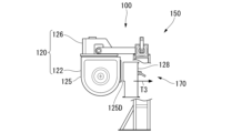
次に、図15を参照して、排出口開閉機構の概略構成について説明する。
図15は、第1実施形態に係るディスク型処理装置の排出口開閉機構の概略を説明する概念図である。
Next, a schematic configuration of the outlet opening and closing mechanism will be described with reference to FIG.
FIG. 15 is a conceptual diagram for explaining an outline of the ejection port opening and closing mechanism of the disk-type processing device according to the first embodiment.
排出口開閉機構170は、排出口蓋部材128と連結するための連結部材(不図示)と、駆動手段(不図示)とを備えている。
そして、排出口開閉機構170は、図15に示すように、例えば、駆動手段(不図示)を作動させることにより、排出口蓋部材128を矢印T1方向に移動させることが可能とされている。
その結果、排出口蓋部材128は、製品排出口125Dに対して接近、離間して、製品排出口125Dを開閉することが可能とされている。
The exhaust port opening and
As shown in FIG. 15, the outlet opening/
As a result, the
開閉蓋部材126がケーシング本体122から離間されている状態で、排出口開閉機構170によって、排出口蓋部材128を製品排出口125Dから離間させて開いた状態とすることで、排出口蓋部材128がケーシング本体122から離れるとともに、ケーシング本体122との間に間隙が形成され、ケーシング本体122が軸線O1周りに傾動可能となる。
When the opening/
次に、図16A~図16Cを参照して、ディスク型処理装置100の動作の概略について説明する。
図16A~図16Cは第1実施形態に係るディスク型処理装置の動作の概略を説明する概念図であり、図16Aは開閉蓋部材が閉塞された状態を、図16Bは開閉蓋部材が開いた状態を、図16Cはケーシング本体が傾動された状態を示している。
Next, the operation of the
Figures 16A to 16C are conceptual diagrams outlining the operation of the disk-type processing device of the first embodiment, with Figure 16A showing the state in which the opening/closing cover member is closed, Figure 16B showing the state in which the opening/closing cover member is open, and Figure 16C showing the state in which the casing body is tilted.
(1)まず、例えば、図16Aに示すように、排出口開閉機構170によって排出口蓋部材128を矢印T3方向に移動させて、製品排出口125Dを開状態とする。
製品排出口125Dを開状態とすることで、排出口蓋部材128がケーシング本体122から離間される。
(1) First, for example, as shown in FIG. 16A, the
By opening the
(2)次に、図16Bに示すように、蓋部材開閉機構150を作動させて、ケーシング本体122から開閉蓋部材126を上方に向かって矢印T4方向に移動させて、開口部122Aを開いた状態とする。
その結果、開閉蓋部材126がケーシング本体122から離間して、ケーシング本体122の傾動が可能な状態となる。
(2) Next, as shown in FIG. 16B, the lid member opening/
As a result, the opening/
(3)次いで、図16Cに示すように、ケーシング傾動機構160を作動させて、ケーシング本体122を回転軸線O1の周りに矢印T5方向に回動して、開口部122Aが下方を向くようにケーシング本体122を傾動させる。
開口部122Aが下方を向くようにケーシング本体122を傾動させることにより、ケーシング本体122の周壁部125の内壁面は、地面に対する傾斜角度が、処理対象物の安息角よりも大きくなるように構成されている。
その結果、ケーシング本体122内に残留していた処理対象物は(不図示)は、ケーシング本体122の周壁部125の内壁面を滑り落ちて開口部122Aからケーシング本体122の外に排出される。
(3) Next, as shown in FIG. 16C, the
By tilting the
As a result, the material to be treated (not shown) remaining within the
第1実施形態に係るディスク型処理装置100によれば、ケーシング傾動機構160によって、開閉蓋部材126が外されたケーシング本体122を、開口部122Aが下方を向くように傾動させることで、ケーシング本体122内の処理対象物を開口部122Aから容易かつ効率的に排出させることができる。
その結果、ケーシング120内に処理対象物が残留するのを抑制することができる。
また、ディスク型処理装置100のケーシング120内の清掃性、洗浄性を向上させることができる。
According to the disk-
As a result, the material to be treated can be prevented from remaining within the
Furthermore, the cleaning and washing properties of the inside of the
また、ディスク型処理装置100によれば、回転軸132と、回転軸132の周囲に軸線O1方向に間隔をあけて形成されたディスク部材136が配置され、送り羽根(処理対象物移送手段)137Aによって処理対象物を移送しながら処理(乾燥または冷却)するので、処理対象物を効率的かつ連続的に処理することができる。
In addition, according to the disk-
また、ディスク型処理装置100によれば、開閉蓋部材126を開閉可能に移動させる蓋部材開閉機構150を備えているので、人手によることなく、開閉蓋部材126を容易かつ効率的に開閉することができる。
In addition, the disk-
また、ディスク型処理装置100によれば、ケーシング傾動機構160が、回転軸O1と同軸の軸線の周りに回動させてケーシング本体122を傾動させるので、ケーシング本体122を傾動させる際のスペースが大きくなるのを抑制することができる。
その結果、ディスク型処理装置100の大型化を抑制して小型化することができる。
Furthermore, according to the disk-
As a result, the disk
また、ディスク型処理装置100によれば、ケーシング本体122に処理が完了した処理物を排出する製品排出口125Dが形成されていて、製品排出口125Dを開閉可能とする排出口蓋部材128を備えているので、排出口蓋部材128により製品排出口125Dを封止することにより、処理対象部が外部に漏れ出したり異物がケーシング120内に混入するのを抑制して処理装置本体110による処理をすることができる。一方、排出口蓋部材128を外して製品排出口125Dを開放することにより、ケーシング本体122との間隙を確保してケーシング120を容易に傾動可能な状態とすることができる。
In addition, according to the disk-
また、ディスク型処理装置100によれば、排出口蓋部材128と連結された排出口開閉機構170を備えていて、排出口開閉機構170は、排出口蓋部材128を製品排出口125Dから離間可能に構成されているので、ケーシング本体122から排出口蓋部材128を容易かつ効率的に外す(離間させる)ことができる。
The disk-
また、ディスク型処理装置100によれば、周壁部125がプレートコイルを用いて形成されているので、ケーシング本体122の強度を向上させることが可能であるとともに、軽量に形成することが可能となり、ケーシング本体122を容易に傾動させることができる。
In addition, according to the disk-
また、ディスク型処理装置100によれば、ケーシング傾動機構160が、ケーシング本体122を傾動するためのインライン減速機168Aを備えているので、ケーシング本体122を効率的に傾動させることが可能となる。また、ケーシング傾動機構160を小型化することができる。
In addition, according to the disk-
なお、上記の実施形態において記載した技術的事項については、上記実施形態に限定されることなく、発明の趣旨を逸脱しない範囲で種々の変更を加えることが可能である。 The technical details described in the above embodiment are not limited to the above embodiment, and various modifications can be made without departing from the spirit of the invention.
例えば、上記実施の形態においては、ケーシング本体122の周壁部125が軸線O1方向に沿って見たときに、略U字形に形成されている場合について説明したが、ケーシング本体122の周壁部125の構成は任意に設定してもよい。
例えば、略U字形の周壁部に代えて、軸線O1に沿って見たときに、略J字形に形成されていてもよい。
For example, in the above embodiment, a case has been described in which the
For example, instead of the substantially U-shaped peripheral wall portion, it may be formed to be substantially J-shaped when viewed along the axis O1.
また、上記実施形態においては、ケーシング傾動機構160が、ケーシング本体122を回転軸132の回転軸線O1と同軸な軸線の周りに回動させて傾動する場合について説明したが、ケーシング本体122を回動させる場合の軸線は回転軸線O1に限定されることなく任意に設定することが可能である。
In addition, in the above embodiment, the case where the
また、上記実施形態においては、ケーシング傾動機構160が手動により操作される構成である場合について説明したが、ケーシング傾動機構160がモータ等の駆動源を備えていてもよく、手動操作とするか駆動源によって作動させるかどうかは任意に設定することが可能である。また、手動操作する場合の傾動機構(減速機)についてもインライン減速機168Aに限定されることなく任意に設定することが可能である。
In addition, in the above embodiment, the case where the
また、上記実施形態においては、蓋部材開閉機構150が開閉蓋部材126を手動操作で開閉する場合について説明したが、蓋部材開閉機構150を手動操作とするか駆動源によって作動させるかは任意に設定することが可能である。
また、手動操作する場合の開閉機構(減速機)についてもインライン減速機158Aに限定されることなく任意に設定することが可能である。
In addition, in the above embodiment, a case has been described in which the lid member opening/
In addition, the opening and closing mechanism (reduction gear) in the case of manual operation is not limited to the in-
また、上記実施形態においては、ケーシング本体122がプレートコイルを用いて形成されている場合について説明したが、ケーシング本体122を形成する際にプレートコイルを用いるかどうかは任意に設定することが可能である。
また、ケーシング本体122をプレートコイルを用いて形成する場合に、どの範囲にプレートコイルを用いるかは任意に設定してもよい。
In addition, in the above embodiment, a case has been described in which the
Furthermore, when the
本発明に係るディスク型処理装置によれば、処理対象物を開口部から容易かつ効率的に排出させることが可能とされ、ケーシング内に処理対象物が残留するのを抑制することができるので産業上利用可能である。 The disk-type processing device according to the present invention can easily and efficiently discharge the object to be processed from the opening, and can prevent the object from remaining in the casing, making it suitable for industrial use.
O1 回転軸線(軸線)
O2 蓋部材回動軸
100 ディスク型処理装置
110 処理装置本体
111 架台ベース
112 支持架台
120 ケーシング
122 ケーシング本体
123L 第1端壁部
123R 第2端壁部
125 周壁部
125D 製品排出口
126 開閉蓋部材
128 排出口蓋部材
130 ディスク回転体
132 回転軸
135 ディスク集合体
136 ディスク部材
137 羽根部材
137A 送り羽根部材(処理対象物移送手段)
140 回転軸駆動部
150 蓋部材開閉機構
160 ケーシング傾動機構
170 排出口開閉機構
O1 Rotation axis (axis)
O2 Lid
140 Rotating
Claims (6)
前記ケーシング本体の前記開口部を開閉可能とされ前記ケーシング本体と協働してケーシングを構成する開閉蓋部材と、
前記第1端壁部と前記第2端壁部に支持され前記ケーシング内に配置されるとともに、軸線の周りに回転可能とされた回転軸と、
前記回転軸の周囲に前記軸線方向に間隔をあけて形成され、前記回転軸とともに回転可能とされた複数のディスク部材と、
前記ディスク部材に配置され、前記ケーシング内において処理対象物を前記軸線方向に沿って移送する処理対象物移送手段と、
前記ケーシング本体を、前記開口部が下方を向くように傾動可能とされたケーシング傾動機構と、
を備え、
前記ケーシング本体の前記周壁部には、処理が完了した処理対象物を排出し、前記開口部とは異なる製品排出口が形成されていて、
前記製品排出口を開閉可能な排出口蓋部材を備え、
加熱媒体または冷却媒体により、処理対象物を加熱または冷却可能であることを特徴とするディスク型処理装置。 a casing body having a first end wall portion disposed on one side, a second end wall portion disposed on the other side, and a peripheral wall portion connected to the first end wall portion on the one side and connected to the second end wall portion on the other side, the peripheral wall portion having an opening formed in an upper portion;
an opening/closing cover member that is capable of opening and closing the opening of the casing body and cooperates with the casing body to form a casing;
a rotating shaft supported by the first end wall portion and the second end wall portion, disposed within the casing, and rotatable about an axis;
a plurality of disk members formed around the rotating shaft at intervals in the axial direction and rotatable together with the rotating shaft;
a processing object transport means disposed on the disk member and configured to transport the processing object within the casing along the axial direction;
a casing tilting mechanism that can tilt the casing body so that the opening faces downward;
Equipped with
A product discharge port that discharges the processed object and is different from the opening is formed on the peripheral wall of the casing body,
A discharge port cover member capable of opening and closing the product discharge port is provided,
A disk-type processing apparatus capable of heating or cooling an object to be processed by a heating medium or a cooling medium .
前記周壁部は、
前記回転軸の軸線に沿って見たときに上方が開口する円弧状壁部と、
前記円弧状壁部の両側の端部から上方に向かって伸びる一対の立上り壁部と、
を有し、
前記製品排出口は、前記一対の立上り壁部の一方に、上下方向に長尺な矩形に形成されている
ことを特徴とするディスク型処理装置。 2. The disk-type processing device according to claim 1,
The peripheral wall portion is
an arc-shaped wall portion that is open upward when viewed along the axis of the rotating shaft;
a pair of rising wall portions extending upward from both end portions of the arcuate wall portion;
having
The disk-type processing apparatus according to claim 1, wherein the product discharge outlet is formed in one of the pair of rising wall portions in a shape of a rectangle that is elongated in the vertical direction.
前記開閉蓋部材を開閉可能に移動させる
蓋部材開閉機構を備えている
ことを特徴とするディスク型処理装置。 2. The disk-type processing device according to claim 1,
a cover member opening and closing mechanism that moves the openable/closable cover member so as to be openable and closable.
前記ケーシング傾動機構は、
前記回転軸と同軸の軸線の周りに回動させて前記ケーシング本体を傾動させる
ことを特徴とするディスク型処理装置。 3. The disk-type processing device according to claim 1,
The casing tilting mechanism includes:
a rotating shaft for rotating the casing body about an axis line coaxial with the rotating shaft, the casing body being tilted.
前記排出口蓋部材と連結され、前記排出口蓋部材により前記製品排出口を開閉する排出口開閉機構を備えている
ことを特徴とするディスク型処理装置。 2. The disk-type processing device according to claim 1,
a discharge port opening/closing mechanism connected to the discharge port cover member for opening and closing the product discharge port by the discharge port cover member.
前記ケーシング傾動機構は、
前記ケーシング本体を傾動するための駆動源を備えている
ことを特徴とするディスク型処理装置。 The disk-type processing device according to any one of claims 1 to 5,
The casing tilting mechanism includes:
A disk-type processing device comprising: a drive source for tilting the casing body.
Priority Applications (3)
| Application Number | Priority Date | Filing Date | Title |
|---|---|---|---|
| JP2020179744A JP7561572B2 (en) | 2020-10-27 | 2020-10-27 | Disk-type processing device |
| KR1020210142590A KR102600730B1 (en) | 2020-10-27 | 2021-10-25 | Disk type processing equipment |
| CN202111240527.8A CN114485123B (en) | 2020-10-27 | 2021-10-25 | Disk type processing device |
Applications Claiming Priority (1)
| Application Number | Priority Date | Filing Date | Title |
|---|---|---|---|
| JP2020179744A JP7561572B2 (en) | 2020-10-27 | 2020-10-27 | Disk-type processing device |
Publications (2)
| Publication Number | Publication Date |
|---|---|
| JP2022070598A JP2022070598A (en) | 2022-05-13 |
| JP7561572B2 true JP7561572B2 (en) | 2024-10-04 |
Family
ID=81492868
Family Applications (1)
| Application Number | Title | Priority Date | Filing Date |
|---|---|---|---|
| JP2020179744A Active JP7561572B2 (en) | 2020-10-27 | 2020-10-27 | Disk-type processing device |
Country Status (3)
| Country | Link |
|---|---|
| JP (1) | JP7561572B2 (en) |
| KR (1) | KR102600730B1 (en) |
| CN (1) | CN114485123B (en) |
Citations (3)
| Publication number | Priority date | Publication date | Assignee | Title |
|---|---|---|---|---|
| JP2002250589A (en) | 2001-02-23 | 2002-09-06 | Tamagawa Machinery Co Ltd | Dryer |
| JP2006349316A (en) | 2005-06-20 | 2006-12-28 | Mitsubishi Materials Techno Corp | Drying equipment |
| JP2014171446A (en) | 2013-03-11 | 2014-09-22 | Sodick Co Ltd | Method and apparatus for agitating/kneading food flour |
Family Cites Families (8)
| Publication number | Priority date | Publication date | Assignee | Title |
|---|---|---|---|---|
| JPH09201580A (en) * | 1996-01-29 | 1997-08-05 | Mitsubishi Materials Corp | Garbage processor with stirring blade |
| JP4449157B2 (en) * | 2000-04-28 | 2010-04-14 | 株式会社明電舎 | Rotating heat treatment method and processing equipment |
| KR100432180B1 (en) * | 2001-09-19 | 2004-05-24 | (주)청호종합기술단 | Drier for food |
| JP2009045525A (en) * | 2007-08-16 | 2009-03-05 | Mitsubishi Materials Techno Corp | Disk type processing equipment |
| CN202182600U (en) * | 2011-06-21 | 2012-04-04 | 大连寅诚表面设备制造有限公司 | Full-automatic centrifugal dying machine |
| JP5372187B2 (en) * | 2012-02-15 | 2013-12-18 | 三菱重工環境・化学エンジニアリング株式会社 | Indirect heating dryer |
| CN110368837A (en) * | 2018-04-12 | 2019-10-25 | 南京华星制药设备有限公司 | Trough type mixing machine |
| CN109590299B (en) * | 2018-11-26 | 2021-06-11 | 太仓韬信信息科技有限公司 | Container cleaning and drying automatic assembly line |
-
2020
- 2020-10-27 JP JP2020179744A patent/JP7561572B2/en active Active
-
2021
- 2021-10-25 KR KR1020210142590A patent/KR102600730B1/en active Active
- 2021-10-25 CN CN202111240527.8A patent/CN114485123B/en active Active
Patent Citations (3)
| Publication number | Priority date | Publication date | Assignee | Title |
|---|---|---|---|---|
| JP2002250589A (en) | 2001-02-23 | 2002-09-06 | Tamagawa Machinery Co Ltd | Dryer |
| JP2006349316A (en) | 2005-06-20 | 2006-12-28 | Mitsubishi Materials Techno Corp | Drying equipment |
| JP2014171446A (en) | 2013-03-11 | 2014-09-22 | Sodick Co Ltd | Method and apparatus for agitating/kneading food flour |
Also Published As
| Publication number | Publication date |
|---|---|
| KR102600730B1 (en) | 2023-11-09 |
| KR20220056131A (en) | 2022-05-04 |
| CN114485123A (en) | 2022-05-13 |
| JP2022070598A (en) | 2022-05-13 |
| CN114485123B (en) | 2024-04-19 |
Similar Documents
| Publication | Publication Date | Title |
|---|---|---|
| US11896021B2 (en) | Rotary screw blancher | |
| US3880407A (en) | Mixer and kneader with counteractive blades | |
| US7735415B2 (en) | Rotary Screw blancher | |
| SU1687025A3 (en) | Disk mixer | |
| JP6159589B2 (en) | Disc type agitator | |
| EP2103892B1 (en) | Machine for heat exchange with a product | |
| JP6796865B2 (en) | A device that heats or cools raw materials | |
| EP2733453B1 (en) | Improved heat-exchanging device for treating liquids and others | |
| JP7561572B2 (en) | Disk-type processing device | |
| JP6155127B2 (en) | Processing object adhesion suppression method, processing object adhesion suppression mechanism, and disk-type processing apparatus | |
| JP4202506B2 (en) | Mixing equipment | |
| US4039024A (en) | Heat exchanger | |
| JP2003222471A (en) | Stirring heat transfer device | |
| GB2072030A (en) | Universal batch processor | |
| JP3935730B2 (en) | Stirring heat transfer device | |
| JP2013044451A (en) | Drying device | |
| GB2200570A (en) | Kneader-mixer | |
| JP3657541B2 (en) | Stirring heat transfer device | |
| US20240407404A1 (en) | Cooling drum for freezing granules and rotary freezing device | |
| CN120094534B (en) | A temperature-controlled vitamin H bromination reactor | |
| JPS635508Y2 (en) | ||
| US20250044008A1 (en) | Rotary freezing device for freezing granules | |
| CN104344688B (en) | Stirring device | |
| JP2019171376A (en) | Separation device for separating solid material from conveying stream and method for maintaining this separation device | |
| JP2000140601A (en) | Mixing dryer |
Legal Events
| Date | Code | Title | Description |
|---|---|---|---|
| A621 | Written request for application examination |
Free format text: JAPANESE INTERMEDIATE CODE: A621 Effective date: 20230825 |
|
| A977 | Report on retrieval |
Free format text: JAPANESE INTERMEDIATE CODE: A971007 Effective date: 20240311 |
|
| A131 | Notification of reasons for refusal |
Free format text: JAPANESE INTERMEDIATE CODE: A131 Effective date: 20240312 |
|
| A521 | Request for written amendment filed |
Free format text: JAPANESE INTERMEDIATE CODE: A523 Effective date: 20240502 |
|
| A131 | Notification of reasons for refusal |
Free format text: JAPANESE INTERMEDIATE CODE: A131 Effective date: 20240604 |
|
| A521 | Request for written amendment filed |
Free format text: JAPANESE INTERMEDIATE CODE: A523 Effective date: 20240805 |
|
| TRDD | Decision of grant or rejection written | ||
| A01 | Written decision to grant a patent or to grant a registration (utility model) |
Free format text: JAPANESE INTERMEDIATE CODE: A01 Effective date: 20240827 |
|
| A61 | First payment of annual fees (during grant procedure) |
Free format text: JAPANESE INTERMEDIATE CODE: A61 Effective date: 20240924 |
|
| R150 | Certificate of patent or registration of utility model |
Ref document number: 7561572 Country of ref document: JP Free format text: JAPANESE INTERMEDIATE CODE: R150 |