JP7561069B2 - Dryer Equipment - Google Patents
Dryer Equipment Download PDFInfo
- Publication number
- JP7561069B2 JP7561069B2 JP2021045843A JP2021045843A JP7561069B2 JP 7561069 B2 JP7561069 B2 JP 7561069B2 JP 2021045843 A JP2021045843 A JP 2021045843A JP 2021045843 A JP2021045843 A JP 2021045843A JP 7561069 B2 JP7561069 B2 JP 7561069B2
- Authority
- JP
- Japan
- Prior art keywords
- drying tube
- desiccant
- drying
- compressed air
- outlet
- Prior art date
- Legal status (The legal status is an assumption and is not a legal conclusion. Google has not performed a legal analysis and makes no representation as to the accuracy of the status listed.)
- Active
Links
- 238000001035 drying Methods 0.000 claims description 195
- 239000002274 desiccant Substances 0.000 claims description 140
- 230000000903 blocking effect Effects 0.000 claims description 23
- 239000002245 particle Substances 0.000 claims description 6
- 230000002093 peripheral effect Effects 0.000 description 6
- 239000000725 suspension Substances 0.000 description 6
- VYPSYNLAJGMNEJ-UHFFFAOYSA-N Silicium dioxide Chemical compound O=[Si]=O VYPSYNLAJGMNEJ-UHFFFAOYSA-N 0.000 description 2
- 229910052782 aluminium Inorganic materials 0.000 description 2
- XAGFODPZIPBFFR-UHFFFAOYSA-N aluminium Chemical compound [Al] XAGFODPZIPBFFR-UHFFFAOYSA-N 0.000 description 2
- 230000006835 compression Effects 0.000 description 2
- 238000007906 compression Methods 0.000 description 2
- 239000007769 metal material Substances 0.000 description 2
- 230000000149 penetrating effect Effects 0.000 description 2
- 238000004080 punching Methods 0.000 description 2
- 239000000741 silica gel Substances 0.000 description 2
- 229910002027 silica gel Inorganic materials 0.000 description 2
- 239000000945 filler Substances 0.000 description 1
Images


Landscapes
- Drying Of Gases (AREA)
Description
本開示は、例えば4輪自動車等の車両に搭載されるドライヤ装置に関する。 This disclosure relates to a dryer device mounted on a vehicle, such as a four-wheeled automobile.
4輪自動車等の車両には、車高調整を行うためのエアサスペンションシステムが搭載されているものがある。エアサスペンションシステムは、圧縮空気を生成するコンプレッサと、圧縮空気中に含まれる水分を除去するドライヤ装置と、を備えている(例えば、特許文献1,2参照)。
Some vehicles, such as four-wheeled automobiles, are equipped with an air suspension system for adjusting the vehicle height. The air suspension system includes a compressor that generates compressed air and a dryer device that removes moisture contained in the compressed air (see, for example,
従来技術によるドライヤ装置は、並列に配置された2本の容器にそれぞれ乾燥剤を充填する構成、内側容器と外側容器とを有する2重の容器にそれぞれ乾燥剤を充填する構成が採用されている。ドライヤ装置には、容器内に充填された乾燥剤を押圧するばねが設けられ、容器内で充填剤が擦れて摩耗するのを防止している。しかし、従来技術では、2本の容器、あるいは内側容器と外側容器にそれぞればねが設けられている。このため、ドライヤ装置の全長が大きくなり、部品点数も多くなるという問題がある。 Conventional dryer devices employ a configuration in which two parallel-arranged containers are filled with desiccant, or a configuration in which a double container having an inner container and an outer container is filled with desiccant. The dryer device is provided with a spring that presses the desiccant filled in the container, preventing the filler from rubbing and wearing out inside the container. However, in conventional technology, a spring is provided for each of the two containers, or the inner container and the outer container. This results in problems such as a large overall length of the dryer device and a large number of parts.
本発明の一実施形態の目的は、装置全体を小型化、軽量化することができるようにしたドライヤ装置を提供することにある。 The objective of one embodiment of the present invention is to provide a dryer device that allows the entire device to be made smaller and lighter.
本発明の一実施形態によるドライヤ装置は、圧縮空気が流入する流入口と、前記流入口から流入した圧縮空気を乾燥させる乾燥剤が充填された第1の乾燥筒と、前記第1の乾燥筒から圧縮空気が流出する第1の流出口と、前記第1の流出口から流出した圧縮空気を乾燥させる乾燥剤が充填された第2の乾燥筒と、前記第2の乾燥筒から圧縮空気が流出する第2の流出口と、前記流入口が設けられ前記第1,第2の乾燥筒の開口部を閉塞する閉塞部材と、を有し、前記第1の乾燥筒には、前記閉塞部材の前記流入口と前記乾燥剤とを仕切る第1のフィルタを設け、前記第2の乾燥筒には前記乾燥剤を押圧するばねを設け、前記第1のフィルタを前記閉塞部材に接触させ、前記ばねにより前記第2の乾燥筒に充填された前記乾燥剤を前記第1の流出口より前記第1の乾燥筒に流動させる。
A dryer device according to one embodiment of the present invention comprises an inlet through which compressed air flows in, a first drying tube filled with a desiccant for drying the compressed air flowing in from the inlet, a first outlet through which compressed air flows out of the first drying tube, a second drying tube filled with a desiccant for drying the compressed air flowing out from the first outlet, a second outlet through which compressed air flows out of the second drying tube, and a blocking member having the inlet and blocking the openings of the first and second drying tubes, wherein the first drying tube is provided with a first filter that separates the inlet of the blocking member from the desiccant, and the second drying tube is provided with a spring that presses the desiccant, the first filter is brought into contact with the blocking member, and the spring causes the desiccant filled in the second drying tube to flow from the first outlet to the first drying tube .
本発明の一実施形態によれば、装置全体を小型化、軽量化することができる。 According to one embodiment of the present invention, the entire device can be made smaller and lighter.
以下、本発明の実施形態によるドライヤ装置を、コンプレッサのシリンダヘッドに取付けた場合を例に挙げ、添付図面に従って詳細に説明する。 The following describes in detail an embodiment of the dryer device of the present invention, using an example in which it is installed on the cylinder head of a compressor, with reference to the attached drawings.
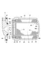
図1ないし図3は第1の実施形態を示している。コンプレッサ1は、例えば車載用のエアサスペンションシステムの一部を構成し、車高調整を行うためのエアサスペンションに供給される圧縮空気を生成する。コンプレッサ1は、シリンダヘッド2と、シリンダヘッド2のシリンダに往復同可能に設けられたピストン(いずれも図示せず)と、電動モータ3とを有する往復動圧縮機として構成されている。コンプレッサ1は、電動モータ3によってピストンが駆動されることにより、吸込管路から吸込んだ空気を圧縮し、シリンダヘッド2に形成された流入口4に吐出する。流入口4に吐出された圧縮空気は、ドライヤ装置11によって水分が除去された状態で、タンク、エアサスペンション等(図示せず)に供給される。
Figures 1 to 3 show a first embodiment. The
ドライヤ装置11は、コンプレッサ1のシリンダヘッド2に一体的に取付けられ、コンプレッサ1が生成した圧縮空気に含まれる水分を除去する。即ち、本実施形態では、コンプレッサ1のシリンダヘッド2は、ドライヤ装置11の一部(閉塞部材)を構成している。ドライヤ装置11は、シリンダヘッド2、流入口4、後述する第1の乾燥筒12、第1の乾燥剤15、第2の乾燥筒18、第1のフィルタ16、第2の乾燥剤21、第2のフィルタ22、ばね24、第1の流出口25、第2の流出口26等を含んで構成されている。
The
シリンダヘッド2は、第1の乾燥筒12の開口端12A、および第2の乾燥筒18の開口端18Aを閉塞する閉塞部材を構成している。シリンダヘッド2には、第1の乾燥筒12内に開口する円錐状の流入口4が形成され、コンプレッサ1によって生成された圧縮空気は、流入口4を通じて第1の乾燥筒12に流入する。
The
図3に示すように、流入口4が開口したシリンダヘッド2の端面は、流入口4を中心とした段付き円筒状に形成され、流入口4の開口端を取囲む小径円筒部2Aと、小径円筒部2Aよりも大径な大径円筒部2Bと、大径円筒部2Bの外周面から径方向外側に円板状に拡径する鍔部2Cとを有している。大径円筒部2Bの軸方向の端面は、第1の乾燥筒12の開口端12Aが当接する第1の当接面2Dとなり、鍔部2Cの軸方向の端面は、第2の乾燥筒18の開口端18Aが当接する第2の当接面2Eとなっている。鍔部2Cの外周縁は、大径円筒部2Bの外周面に全種に亘って対面する円筒状の周壁部2Fとなっている。
As shown in FIG. 3, the end surface of the
第1の乾燥筒12は、シリンダヘッド2に取付けられている。第1の乾燥筒12は、例えばアルミニウム等の金属材料を用いて円筒状に形成され、流入口4と同心上に配置されている。第1の乾燥筒12の軸方向の一端は開口端12Aとなり、この開口端12Aは、シリンダヘッド2の第1の当接面2Dに当接している。
The
第1の乾燥筒12の開口端12A側は、シリンダヘッド2の小径円筒部2Aの外周側に配置され、小径円筒部2Aの外周面と第1の乾燥筒12との間は、Oリング13によって気密にシールされている。第1の乾燥筒12の軸方向の他端12Bは、第2の乾燥筒18の底部18Bによって閉塞されている。これにより、第1の乾燥筒12の内周側には、内側乾燥剤室14が形成されている。
The
第1の乾燥剤15は、第1の乾燥筒12内(内側乾燥剤室14)に充填されている。第1の乾燥剤15は、例えば球状に成形されたシリカゲルにより構成され、第1の乾燥筒12内に流入した圧縮空気中の水分を吸着する。
The
第1のフィルタ16は、第1の乾燥筒12の開口端12A側に位置して内側乾燥剤室14内に設けられている。第1のフィルタ16は、第1の乾燥剤15の粒径よりも小径な無数の小孔(網目)を有し、第1の乾燥筒12の内径寸法と同等な外径寸法を有する円板状に形成されている。第1のフィルタ16は、フィルタ押え17を介してシリンダヘッド2の小径円筒部2Aに接触し、シリンダヘッド2の流入口4と第1の乾燥筒12に充填された第1の乾燥剤15とを仕切っている。
The
フィルタ押え17は、シリンダヘッド2の小径円筒部2Aと第1のフィルタ16との間に設けられている。フィルタ押え17は、第1のフィルタ16と同等な外径寸法を有する円板(パンチングボード)からなり、板厚方向に貫通する多数の小孔が設けられている。フィルタ押え17は、第1のフィルタ16が第1の乾燥筒12の軸中心に対して直交する姿勢を保つように、第1のフィルタ16を押えている。
The
第2の乾燥筒18は、第1の乾燥筒12を外周側から覆った状態でシリンダヘッド2に取付けられている。第2の乾燥筒18は、例えばアルミニウム等の金属材料を用いて有底円筒状に形成され、第1の乾燥筒12と同心上に配置されている。第2の乾燥筒18は、ドライヤ装置11の外殻を構成し、ドライヤ装置11は、第1の乾燥筒12と第2の乾燥筒18との二重筒構造となっている。
The
第2の乾燥筒18の軸方向の一端は開口端18Aとなり、この開口端18Aは、シリンダヘッド2の第2の当接面2Eに当接している。第2の乾燥筒18の開口端18A側は、シリンダヘッド2の周壁部2Fの内周側に配置され、周壁部2Fの内周面と第2の乾燥筒18との間は、Oリング19によって気密にシールされている。第2の乾燥筒18の軸方向の他端は底部18Bとなり、底部18Bの内側面には、開口端18A側に突出する円筒状の嵌合突起18Cが設けられている。第1の乾燥筒12の他端12Bは、嵌合突起18Cの外周面に嵌合することにより、底部18Bによって閉塞されている。これにより、第2の乾燥筒18の内周側(第1の乾燥筒12の外周面と第2の乾燥筒18の内周面との間)には、全周に亘って円筒状の空間からなる外側乾燥剤室20が形成されている。
One axial end of the
第2の乾燥剤21は、第2の乾燥筒18内(外側乾燥剤室20)に充填されている。第2の乾燥剤21は、例えば第1の乾燥剤15と同一の球状のシリカゲルにより構成され、第2の乾燥筒18内に流入した圧縮空気中の水分を吸着する。
The
第2のフィルタ22は、第2の乾燥筒18の開口端18A側に位置して外側乾燥剤室20内に設けられている。第2のフィルタ22は、第2の乾燥剤21の粒径よりも小径な無数の小孔(網目)を有し、第1の乾燥筒12の外径寸法と同等な内径寸法で、かつ第2の乾燥筒18の内径寸法と同等な外径寸法を有するリング状に形成されている。第2のフィルタ22は、後述する第2の流出口26と第2の乾燥筒18に充填された第2の乾燥剤21とを仕切っている。
The
フィルタ押え23は、第2のフィルタ22を挟んで第2の乾燥剤21とは反対側に配置され、第2の乾燥筒18の内周側(外側乾燥剤室20内)に設けられている。フィルタ押え23は、第2のフィルタ22と同等な内径寸法および外径寸法を有するリング状の板体(パンチングボード)からなり、板厚方向に貫通する多数の小孔が設けられている。第2のフィルタ22およびフィルタ押え23は、後述のばね24に押圧されることにより、外側乾燥剤室20内を第2の乾燥筒18の軸方向に移動可能となっている。フィルタ押え23は、第2のフィルタ22が第2の乾燥筒18の軸中心に対して直交する姿勢を保つように、第2のフィルタ22を押えている。
The
ばね24は、シリンダヘッド2の鍔部2Cとフィルタ押え23との間に位置して第2の乾燥筒18の内周側(外側乾燥剤室20)に設けられている。ばね24は、第1の乾燥筒12の外径寸法よりも大きく、かつ第2の乾燥筒18の内径寸法よりも小さい外径寸法を有する圧縮ばねにより構成されている。ばね24の軸方向の一端は、シリンダヘッド2の第2の当接面2Eに当接し、ばね24の軸方向の他端は、フィルタ押え23に当接している。ばね24は、第1の乾燥筒12および第2の乾燥筒18をシリンダヘッド2に取付けた状態で、第2の当接面2Eとフィルタ押え23との間に縮装される。これにより、ばね24は、フィルタ押え23および第2のフィルタ22を介して、第2の乾燥剤21を第2の乾燥筒18の軸方向に押圧する。
The
第1の流出口25は、第1の乾燥筒12の他端12B側に設けられている。第1の流出口25は、第1の乾燥筒12の外周側を全周覆うように複数個設けられ、これら第1の流出口25は、周方向に適度な角度間隔をもって配置されている。第1の流出口25の口径は、第1,第2の乾燥剤15,21の粒径の2倍以上、かつ第1の乾燥筒12の長さ方向の1/3以下の範囲に設定されている。これら複数の第1の流出口25は、内側乾燥剤室14と外側乾燥剤室20との間を連通させ、コンプレッサ1から第1の乾燥筒12内(内側乾燥剤室14)に流入した圧縮空気を、第2の乾燥筒18(外側乾燥剤室20)へと流出させる。また、第2の乾燥筒18内に充填された第2の乾燥剤21は、ばね24に押圧されることにより、図2中の矢印F1で示すように、第1の流出口25を通じて第1の乾燥筒12内へと流動することができる構成となっている。なお、第1の流出口は1個でもよい。
The
第2の流出口26は、シリンダヘッド2の鍔部2Cに設けられている。第2の流出口26は、外側乾燥剤室20に開口し、第2の乾燥筒18内(外側乾燥剤室20)に流入した圧縮空気を、タンク等(図示せず)へと流出させる。
The
図3に示すように、ドライヤ装置11をシリンダヘッド2に取付けるときには、第1の乾燥筒12内に充填された第1の乾燥剤15が、第1のフィルタ16およびフィルタ押え17を介してシリンダヘッド2の小径円筒部2Aの端面に接触する。このため、第1の乾燥剤15は、詰め過ぎないように互いに適度な隙間をもって第1の乾燥筒12内に充填される。従って、第2の乾燥筒18内に充填された第2の乾燥剤21は、第1の流出口25を通じて第1の乾燥筒12内へと流動することにより、第1の乾燥剤15間に形成された隙間を埋める必要がある。
As shown in FIG. 3, when the
このため、第2の乾燥筒18の開口端18Aから第2の乾燥剤21の先端部までの距離Aを、第1の乾燥筒12の開口端12Aから第1の乾燥剤15の先端部までの距離Bよりも大きく設定する。これにより、ドライヤ装置11をシリンダヘッド2に取付けたときに、ばね24による適度な力で第2の乾燥剤21を押圧することができ、第2の乾燥剤21を円滑に第1の乾燥筒12内へと流動させることができる。従って、第1の乾燥筒12に最適な密度で第1,第2の乾燥剤15,21を充填すると共に、第2の乾燥筒18に最適な密度で第2の乾燥剤21を充填することができる構成となっている。
For this reason, the distance A from the
本実施形態によるドライヤ装置11は、上述の如き構成を有するもので、コンプレッサ1を搭載した車両の走行時に、コンプレッサ1から吐出した圧縮空気は、シリンダヘッド2の流入口4からドライヤ装置11の第1の乾燥筒12内に流入する。この圧縮空気は、第1の乾燥筒12の他端12B側に形成された第1の流出口25を通じて第2の乾燥筒18内へと流出した後、シリンダヘッド2の鍔部2Cに形成された第2の流出口26を通じてタンク等へと流出する。
The
このように、コンプレッサ1からドライヤ装置11に吐出された圧縮空気は、第1の乾燥筒12内を流れる間に第1の乾燥剤15によって水分が吸着され、第2の乾燥筒18内を流れる間に第2の乾燥剤21によって水分が吸着される。このように、ドライヤ装置11は、第1の乾燥筒12と第2の乾燥筒18とによって圧縮空気の流通経路を可及的に大きく確保することができる。この結果、ドライヤ装置11によって圧縮空気中の水分を十分に除去することができ、乾燥した圧縮空気をタンク、エアサスペンション等に供給することができる。
In this way, the compressed air discharged from the
ここで、コンプレッサ1の作動時の振動や車両の走行時の振動により、第1の乾燥筒12に充填された多数の第1の乾燥剤15間に隙間が生じる可能性がある。第1の乾燥剤15間に隙間が生じた場合には、この隙間内で第1の乾燥剤15が振動して互いに擦れることにより、第1の乾燥剤15が摩耗や、破砕してしまうという問題がある。第2の乾燥筒18に充填された第2の乾燥剤21についても、同様の問題がある。
Here, there is a possibility that gaps will occur between the numerous
これに対し、本実施形態によるドライヤ装置11は、第2の乾燥筒18に充填した第2の乾燥剤21を、ばね24によって第2の乾燥筒18の底部18Bに向けて押圧している。これにより、第2の乾燥剤21間の隙間が除去され、第2の乾燥筒18内(外側乾燥剤室20)における第2の乾燥剤21の密度が高まる。この結果、コンプレッサ1の作動時の振動等によって第2の乾燥剤21が振動して互いに擦れるのを抑制することができ、第2の乾燥剤21の摩耗を防止することができる。
In contrast, in the
さらに、ドライヤ装置11は、第1の乾燥筒12に、第1の乾燥筒12の内部と第2の乾燥筒18の内部とを連通させる第1の流出口25を設け、この第1の流出口25を通じて、第1の乾燥筒12に充填された第1の乾燥剤15を第2の乾燥筒18へと流動させる構成としている。
Furthermore, the
これにより、第1の乾燥筒12内に充填された第1の乾燥剤15間に、コンプレッサ1の作動時の振動等によって隙間が生じた場合には、ばね24によって押圧された第2の乾燥剤21が、第1の流出口25を通じて第1の乾燥筒12内へと流動する。この第2の乾燥剤21の流動により、第1の乾燥剤15間に生じた隙間が除去され、第1の乾燥筒12内における第1の乾燥剤15の密度が高まる。この結果、コンプレッサ1の作動時の振動等によって第1の乾燥剤15が振動して互いに擦れるのを抑制することができ、第1の乾燥剤15の摩耗を防止することができる。
As a result, if gaps occur between the
この場合、第1の流出口25は、第1の乾燥筒12の外周側を全周覆うように、周方向に適度な角度間隔をもって複数設けられている。このため、第1の流出口25を通じて第1の乾燥筒12内へと向かう第2の乾燥剤21の流動を、第1の乾燥筒12の周方向で均一化することができる。この結果、第1の乾燥剤15間に生じた隙間内に、第2の乾燥剤21を迅速に充填することができ、第1の乾燥筒12内における第1の乾燥剤15の密度を効率良く高めることができる。
In this case, the
しかも、ドライヤ装置11は、第2の乾燥筒18の内周側に設けた1本のばね24により、第2の乾燥剤21のみを押圧する構成としている。従って、例えば従来技術のように、2つの容器に充填された乾燥剤を個別に押圧するために2本のばねを設ける構成に比較して、ばねの本数を削減することができる。この結果、ばね1本分の長さ寸法を省略することができ、ドライヤ装置11全体の小型化、軽量化を図ることができる。また、ばねを省略することによりコストの低減にも寄与することができる。
Moreover, the
かくして、本実施形態によるドライヤ装置11は、圧縮空気が流入する流入口4と、流入口4から流入した圧縮空気を乾燥させる第1の乾燥剤15が充填された第1の乾燥筒12と、第1の乾燥筒12から圧縮空気が流出する第1の流出口25と、第1の流出口25から流出した圧縮空気を乾燥させる第2の乾燥剤が充填された第2の乾燥筒18と、第2の乾燥筒18から圧縮空気が流出する第2の流出口26と、流入口4が設けられ第1,第2の乾燥筒12,18の開口端12A,18Aを閉塞するシリンダヘッド2と、を有し、第1の乾燥筒12には、シリンダヘッド2の流入口4と第1の乾燥剤15とを仕切る第1のフィルタ16を設け、第2の乾燥筒18には第2の乾燥剤21を押圧するばね24を設けている。これにより、第1の乾燥筒12内に充填された第1の乾燥剤15間に、コンプレッサ1の作動時の振動等によって隙間が生じた場合には、ばね24によって押圧された第2の乾燥剤21が、第1の流出口25を通じて第1の乾燥筒12内へと流動することにより、第1の乾燥剤15間の隙間が除去される。この結果、第1の乾燥筒12内における第1の乾燥剤15の密度が高まるので、第1の乾燥剤15が振動して互いに擦れるのを抑制することができる。
Thus, the
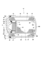
次に、図4は本発明の第2の実施形態を示している。本実施形態の特徴は、第1の乾燥筒にばねを設けたことにある。なお、第2の実施形態では、第1の実施形態と同一の構成要素に同一符号を付し、その説明を省略する。 Next, FIG. 4 shows a second embodiment of the present invention. The feature of this embodiment is that a spring is provided in the first drying tube. In the second embodiment, the same components as those in the first embodiment are given the same reference numerals, and their explanation will be omitted.
第2の実施形態によるドライヤ装置41は、第1の実施形態によるドライヤ装置11と同様に、シリンダヘッド2、流入口4、第1の乾燥筒12、第1の乾燥剤15、第2の乾燥筒18、第1のフィルタ16、第2の乾燥剤21、第2のフィルタ22、第1の流出口25、第2の流出口26等を含んで構成されている。しかし、ドライヤ装置41は、第1の乾燥筒12内に後述のばね42を設けた点で、第1の実施形態とは異なっている。
The
シリンダヘッド2に形成された小径円筒部2Aの軸方向端面には、流入口4を取り囲む環状のばね取付溝2Gが形成されている。ばね42は、シリンダヘッド2の小径円筒部2A(ばね取付溝2G)とフィルタ押え17との間に位置して第1の乾燥筒12の内周側(内側乾燥剤室14)に設けられている。ばね42は、第1の乾燥筒12の内径寸法よりも小さい外径寸法を有する圧縮ばねにより構成されている。ばね42の軸方向の一端は、シリンダヘッド2のばね取付溝2Gに当接し、ばね42の軸方向の他端は、フィルタ押え17に当接している。
A ring-shaped
ばね42は、第1の乾燥筒12および第2の乾燥筒18をシリンダヘッド2に取付けた状態で、ばね取付溝2Gとフィルタ押え17との間に縮装される。ばね42は、フィルタ押え17および第1のフィルタ16を介して、第1の乾燥剤15を第1の乾燥筒12の軸方向に押圧する。これにより、第1の乾燥筒12内に充填された第1の乾燥剤15は、ばね42に押圧され、図4中の矢印F2で示すように、第1の流出口25を通じて第2の乾燥筒18内へと流動することができる構成となっている。
The
第2の実施形態によるドライヤ装置41は上述の如き構成を有するもので、第2の乾燥筒18内に充填された第2の乾燥剤21間に、コンプレッサ1の作動時の振動等によって隙間が生じた場合には、ばね42によって押圧された第1の乾燥剤15が、第1の流出口25を通じて第2の乾燥筒18内へと流動する。この第1の乾燥剤15の流動により、第2の乾燥剤21間の隙間が除去され、第2の乾燥筒18内(外側乾燥剤室20)における第2の乾燥剤21の密度が高まる。この結果、コンプレッサ1の作動時の振動等によって第2の乾燥剤21が振動して互いに擦れるのを抑制することができ、第2の乾燥剤21の摩耗を防止することができる。
The
次に、図5は本発明の第3の実施形態を示している。本実施形態の特徴は、ドライヤ装置を、コンプレッサとは別体の独立した装置として構成したことにある。なお、第3の実施形態では、第1の実施形態と同一の構成要素に同一符号を付し、その説明を省略する。 Next, FIG. 5 shows a third embodiment of the present invention. The feature of this embodiment is that the dryer device is configured as an independent device separate from the compressor. In the third embodiment, the same components as in the first embodiment are given the same reference numerals, and their description will be omitted.
図5に示すドライヤ装置51は、第1の実施形態によるドライヤ装置11と同様に、流入口4、第1の乾燥筒12、第1の乾燥剤15、第2の乾燥筒18、第1のフィルタ16、第2の乾燥剤21、第2のフィルタ22、第1の流出口25、後述する第2の流出口54等を含んで構成されている。しかし、ドライヤ装置51は、閉塞部材としてシリンダヘッド2とは異なる蓋体52を用いる点で第1の実施形態とは異なっている。
The
蓋体52は、第1の乾燥筒12の開口端12Aおよび第2の乾燥筒18の開口端18Aを閉塞する閉塞部材を構成している。蓋体52の中心部には流入口4が形成され、この流入口4は、管路53を介してコンプレッサ(図示せず)に接続される。蓋体52には、第1の実施形態で用いたシリンダヘッド2と同様に、小径円筒部52A、大径円筒部52B、鍔部52C、第1の当接面52D、第2の当接面52E、周壁部52Fが設けられている。
The
第1の乾燥筒12は、小径円筒部52Aの外周側にOリング13を介して配置され、開口端12Aは、第1の当接面52Dに当接している。第2の乾燥筒18は、周壁部52Fの内周側にOリング19を介して配置され、開口端18Aは、第2の当接面52Eに当接している。蓋体52の鍔部52Cには、第2の乾燥筒18内(外側乾燥剤室20)に開口する第2の流出口54が設けられている。
The
本実施形態によるドライヤ装置51は上述の如き構成を有するもので、その基本的作用については、第1の実施形態によるドライヤ装置11と格別差異はない。然るに、本実施形態によるドライヤ装置51は、コンプレッサとは別の独立した装置として構成されているので、管路53を介して種々のコンプレッサに取付けることができる。
The
なお、実施形態では、第1の乾燥剤15と第2の乾燥剤21とを、同一の乾燥剤によって構成した場合を例示している。しかし、本発明はこれに限らず、第1の乾燥剤と第2の乾燥剤の種類を異なるものとしても良い。
In the embodiment, the
次に、上記実施形態に含まれるドライヤ装置として、例えば、以下に述べる態様のものが考えられる。 Next, the dryer device included in the above embodiment may have the following configuration, for example.
第1の態様としては、圧縮空気が流入する流入口と、前記流入口から流入した圧縮空気を乾燥させる乾燥剤が充填された第1の乾燥筒と、前記第1の乾燥筒から圧縮空気が流出する第1の流出口と、前記第1の流出口から流出した圧縮空気を乾燥させる乾燥剤が充填された第2の乾燥筒と、前記第2の乾燥筒から圧縮空気が流出する第2の流出口と、前記流入口が設けられ前記第1,第2の乾燥筒の開口部を閉塞する閉塞部材と、を有し、前記第1の乾燥筒には、前記閉塞部材の前記流入口と前記乾燥剤とを仕切る第1のフィルタを設け、前記第1,第2の乾燥筒のいずれか一方には前記乾燥剤を押圧するばねを設け、前記ばねにより前記第1の流出口を通じて前記乾燥剤を流動させる. In the first aspect, the drying tube has an inlet through which compressed air flows, a first drying tube filled with a desiccant that dries the compressed air that flows in from the inlet, a first outlet through which compressed air flows out of the first drying tube, a second outlet through which compressed air flows out of the second drying tube, and a blocking member that has the inlet and blocks the openings of the first and second drying tubes, and the first drying tube is provided with a first filter that separates the inlet of the blocking member from the desiccant, and one of the first and second drying tubes is provided with a spring that presses the desiccant, and the spring causes the desiccant to flow through the first outlet.
第2の態様としては、前記第2の乾燥筒に前記ばねを設け、前記第1のフィルタを前記閉塞部材に接触させ、前記第2の乾燥筒に充填された前記乾燥剤を前記第1の流出口より前記第1の乾燥筒に流動させる。 In a second embodiment, the spring is provided in the second drying tube, the first filter is brought into contact with the blocking member, and the desiccant filled in the second drying tube is caused to flow from the first outlet into the first drying tube.
第3の態様としては、前記第1の乾燥筒にばねを設け、前記第2の乾燥筒に設けた第2のフィルタを前記閉塞部材に接触させ、前記第1の乾燥筒に充填された前記乾燥剤を前記第1の流出口より前記第2の乾燥筒に流動させる。 In a third embodiment, a spring is provided in the first drying tube, a second filter provided in the second drying tube is brought into contact with the blocking member, and the desiccant filled in the first drying tube is caused to flow from the first outlet into the second drying tube.
第4の態様としては、前記第1の流出口の口径は、前記乾燥剤の粒径の2倍以上に設定されている。 In a fourth aspect, the aperture of the first outlet is set to be at least twice the particle size of the desiccant.
第5の態様としては、前記第1の乾燥筒の外周側を全周覆うように前記第1の流出口を設け、乾燥剤の流動を均一化している。 In a fifth aspect, the first outlet is provided to completely cover the outer periphery of the first drying tube, making the flow of the desiccant uniform.
第6の態様としては、前記閉塞部材は、圧縮空気を生成するコンプレッサのシリンダヘッドである。 In a sixth aspect, the blocking member is a cylinder head of a compressor that generates compressed air.
1 コンプレッサ
2 シリンダヘッド
4 流入口
11,41,51 ドライヤ装置
12 第1の乾燥筒
12A,18A 開口端
15 第1の乾燥剤(乾燥剤)
16 第1のフィルタ
18 第2の乾燥筒
21 第2の乾燥剤(乾燥剤)
24,42 ばね
25 第1の流出口
26,54 第2の流出口
REFERENCE SIGNS
16
24, 42
Claims (5)
前記流入口から流入した圧縮空気を乾燥させる乾燥剤が充填された第1の乾燥筒と、
前記第1の乾燥筒から圧縮空気が流出する第1の流出口と、
前記第1の流出口から流出した圧縮空気を乾燥させる乾燥剤が充填された第2の乾燥筒と、
前記第2の乾燥筒から圧縮空気が流出する第2の流出口と、
前記流入口が設けられ前記第1,第2の乾燥筒の開口部を閉塞する閉塞部材と、
を有し、
前記第1の乾燥筒には、前記閉塞部材の前記流入口と前記乾燥剤とを仕切る第1のフィルタを設け、
前記第2の乾燥筒には前記乾燥剤を押圧するばねを設け、前記第1のフィルタを前記閉塞部材に接触させ、
前記ばねにより前記第2の乾燥筒に充填された前記乾燥剤を前記第1の流出口より前記第1の乾燥筒に流動させるドライヤ装置。 An inlet through which compressed air flows;
a first drying tube filled with a desiccant for drying the compressed air flowing in from the inlet;
a first outlet through which compressed air flows out of the first drying tube;
a second drying tube filled with a desiccant for drying the compressed air flowing out from the first outlet;
a second outlet through which compressed air flows out of the second drying tube;
a blocking member that is provided with the inflow port and blocks the openings of the first and second drying tubes;
having
the first drying tube is provided with a first filter that separates the inlet of the blocking member from the desiccant;
a spring for pressing the desiccant in the second drying tube is provided, and the first filter is brought into contact with the blocking member;
a spring for causing the desiccant filled in the second drying tube to flow from the first outlet into the first drying tube ;
前記流入口から流入した圧縮空気を乾燥させる乾燥剤が充填された第1の乾燥筒と、
前記第1の乾燥筒から圧縮空気が流出する第1の流出口と、
前記第1の流出口から流出した圧縮空気を乾燥させる乾燥剤が充填された第2の乾燥筒と、
前記第2の乾燥筒から圧縮空気が流出する第2の流出口と、
前記流入口が設けられ前記第1,第2の乾燥筒の開口部を閉塞する閉塞部材と、
を有し、
前記第1の乾燥筒には、前記閉塞部材の前記流入口と前記乾燥剤とを仕切る第1のフィルタを設け、
前記第1の乾燥筒には前記乾燥剤を押圧するばねを設け、前記第2の乾燥筒に設けた第2のフィルタを前記閉塞部材に接触させ、
前記ばねにより前記第1の乾燥筒に充填された前記乾燥剤を前記第1の流出口より前記第2の乾燥筒に流動させるドライヤ装置。 An inlet through which compressed air flows;
a first drying tube filled with a desiccant for drying the compressed air flowing in from the inlet;
a first outlet through which compressed air flows out of the first drying tube;
a second drying tube filled with a desiccant for drying the compressed air flowing out from the first outlet;
a second outlet through which compressed air flows out of the second drying tube;
a blocking member that is provided with the inflow port and blocks the openings of the first and second drying tubes;
having
the first drying tube is provided with a first filter that separates the inlet of the blocking member from the desiccant;
a spring for pressing the desiccant is provided in the first drying tube, and a second filter provided in the second drying tube is brought into contact with the blocking member;
a spring for causing the desiccant filled in the first drying tube to flow from the first outlet to the second drying tube;
前記流入口から流入した圧縮空気を乾燥させる乾燥剤が充填された第1の乾燥筒と、
前記第1の乾燥筒から圧縮空気が流出する第1の流出口と、
前記第1の流出口から流出した圧縮空気を乾燥させる乾燥剤が充填された第2の乾燥筒と、
前記第2の乾燥筒から圧縮空気が流出する第2の流出口と、
前記流入口が設けられ前記第1,第2の乾燥筒の開口部を閉塞する閉塞部材と、
を有し、
前記第1の乾燥筒には、前記閉塞部材の前記流入口と前記乾燥剤とを仕切る第1のフィルタを設け、
前記第1,第2の乾燥筒のいずれか一方には前記乾燥剤を押圧するばねを設け、前記ばねにより前記第1の流出口を通じて前記乾燥剤を流動させ、
前記第1の乾燥筒の外周側を全周覆うように前記第1の流出口を設け、前記乾燥剤の流動を均一化したドライヤ装置。 An inlet through which compressed air flows;
a first drying tube filled with a desiccant for drying the compressed air flowing in from the inlet;
a first outlet through which compressed air flows out of the first drying tube;
a second drying tube filled with a desiccant for drying the compressed air flowing out from the first outlet;
a second outlet through which compressed air flows out of the second drying tube;
a blocking member that is provided with the inflow port and blocks the openings of the first and second drying tubes;
having
the first drying tube is provided with a first filter that separates the inlet of the blocking member from the desiccant;
a spring for pressing the desiccant is provided in one of the first and second drying tubes, and the spring causes the desiccant to flow through the first outlet;
The first outlet is provided so as to cover the entire outer periphery of the first drying tube, thereby making the flow of the desiccant uniform.
前記流入口から流入した圧縮空気を乾燥させる乾燥剤が充填された第1の乾燥筒と、
前記第1の乾燥筒から圧縮空気が流出する第1の流出口と、
前記第1の流出口から流出した圧縮空気を乾燥させる乾燥剤が充填された第2の乾燥筒と、
前記第2の乾燥筒から圧縮空気が流出する第2の流出口と、
前記流入口が設けられ前記第1,第2の乾燥筒の開口部を閉塞する閉塞部材と、
を有し、
前記第1の乾燥筒には、前記閉塞部材の前記流入口と前記乾燥剤とを仕切る第1のフィルタを設け、
前記第1,第2の乾燥筒のいずれか一方には前記乾燥剤を押圧するばねを設け、前記ばねにより前記第1の流出口を通じて前記乾燥剤を流動させ、
前記閉塞部材は、圧縮空気を生成するコンプレッサのシリンダヘッドであるドライヤ装置。 An inlet through which compressed air flows;
a first drying tube filled with a desiccant for drying the compressed air flowing in from the inlet;
a first outlet through which compressed air flows out of the first drying tube;
a second drying tube filled with a desiccant for drying the compressed air flowing out from the first outlet;
a second outlet through which compressed air flows out of the second drying tube;
a blocking member that is provided with the inflow port and blocks the openings of the first and second drying tubes;
having
the first drying tube is provided with a first filter that separates the inlet of the blocking member from the desiccant;
a spring for pressing the desiccant is provided in one of the first and second drying tubes, and the spring causes the desiccant to flow through the first outlet;
The closing member is a cylinder head of a compressor that generates compressed air.
Priority Applications (1)
| Application Number | Priority Date | Filing Date | Title |
|---|---|---|---|
| JP2021045843A JP7561069B2 (en) | 2021-03-19 | 2021-03-19 | Dryer Equipment |
Applications Claiming Priority (1)
| Application Number | Priority Date | Filing Date | Title |
|---|---|---|---|
| JP2021045843A JP7561069B2 (en) | 2021-03-19 | 2021-03-19 | Dryer Equipment |
Publications (2)
| Publication Number | Publication Date |
|---|---|
| JP2022144709A JP2022144709A (en) | 2022-10-03 |
| JP7561069B2 true JP7561069B2 (en) | 2024-10-03 |
Family
ID=83455071
Family Applications (1)
| Application Number | Title | Priority Date | Filing Date |
|---|---|---|---|
| JP2021045843A Active JP7561069B2 (en) | 2021-03-19 | 2021-03-19 | Dryer Equipment |
Country Status (1)
| Country | Link |
|---|---|
| JP (1) | JP7561069B2 (en) |
Citations (3)
| Publication number | Priority date | Publication date | Assignee | Title |
|---|---|---|---|---|
| JP2004538123A (en) | 1998-10-29 | 2004-12-24 | ベンディックス コマーシャル ヴィヒクル システムズ リミテッド ライアビリティ カンパニー | Single plate compression and sealing design for compressed air dryer |
| CN105169898A (en) | 2015-07-10 | 2015-12-23 | 浙江诸暨东港液压机械有限公司 | Commercial vehicle air dryer vibration regeneration type drying tank |
| WO2018074107A1 (en) | 2016-10-21 | 2018-04-26 | 日立オートモティブシステムズ株式会社 | Dryer device and air suspension system |
-
2021
- 2021-03-19 JP JP2021045843A patent/JP7561069B2/en active Active
Patent Citations (3)
| Publication number | Priority date | Publication date | Assignee | Title |
|---|---|---|---|---|
| JP2004538123A (en) | 1998-10-29 | 2004-12-24 | ベンディックス コマーシャル ヴィヒクル システムズ リミテッド ライアビリティ カンパニー | Single plate compression and sealing design for compressed air dryer |
| CN105169898A (en) | 2015-07-10 | 2015-12-23 | 浙江诸暨东港液压机械有限公司 | Commercial vehicle air dryer vibration regeneration type drying tank |
| WO2018074107A1 (en) | 2016-10-21 | 2018-04-26 | 日立オートモティブシステムズ株式会社 | Dryer device and air suspension system |
Also Published As
| Publication number | Publication date |
|---|---|
| JP2022144709A (en) | 2022-10-03 |
Similar Documents
| Publication | Publication Date | Title |
|---|---|---|
| US5851269A (en) | Air desiccant canister for an air brake system | |
| CN1124174C (en) | Cartridge for air drier | |
| JP5732756B2 (en) | Vehicle air suspension dryer | |
| US8906145B2 (en) | Compressed air supply device for a utility vehicle and air dryer cartridge | |
| EP1048540A1 (en) | Air desiccant canister | |
| US8852327B1 (en) | Air dryer cartridge with integrated check valve | |
| JPH10103540A (en) | Valve sealing system, check valve closing element used in valve sealing system, and check valve using valve sealing system | |
| JP5298922B2 (en) | Vehicle air suspension dryer | |
| CN105050874A (en) | Air cleaner element with integrated coalescing filter/coarse dirt filter and desiccant fill | |
| JP2004538123A (en) | Single plate compression and sealing design for compressed air dryer | |
| US10723341B2 (en) | Air dryer cartridge | |
| JP2000351363A (en) | Drying agent drier | |
| JP7561069B2 (en) | Dryer Equipment | |
| KR102438981B1 (en) | Pre-filter holder of air dryer cartridge for commercial vehicle and air dryer cartridge including same | |
| WO2001052973A1 (en) | Air dryer cartridge with coalescing filter | |
| US7691163B2 (en) | Vehicle air dryer | |
| US10590889B2 (en) | Canister | |
| JP4953417B2 (en) | Air dryer | |
| KR102688043B1 (en) | Air dryer filter assembly | |
| KR20220049572A (en) | Non-return valve device | |
| JP4566676B2 (en) | air compressor | |
| RU2718930C1 (en) | Air-drier cartridge | |
| KR102463454B1 (en) | Silencer for clutch air booster | |
| JP6662029B2 (en) | Dryer for air suspension | |
| JP2015039673A (en) | Compressed air drying apparatus |
Legal Events
| Date | Code | Title | Description |
|---|---|---|---|
| A621 | Written request for application examination |
Free format text: JAPANESE INTERMEDIATE CODE: A621 Effective date: 20230628 |
|
| A977 | Report on retrieval |
Free format text: JAPANESE INTERMEDIATE CODE: A971007 Effective date: 20240221 |
|
| A131 | Notification of reasons for refusal |
Free format text: JAPANESE INTERMEDIATE CODE: A131 Effective date: 20240326 |
|
| A521 | Request for written amendment filed |
Free format text: JAPANESE INTERMEDIATE CODE: A523 Effective date: 20240520 |
|
| TRDD | Decision of grant or rejection written | ||
| A01 | Written decision to grant a patent or to grant a registration (utility model) |
Free format text: JAPANESE INTERMEDIATE CODE: A01 Effective date: 20240827 |
|
| A61 | First payment of annual fees (during grant procedure) |
Free format text: JAPANESE INTERMEDIATE CODE: A61 Effective date: 20240920 |
|
| R150 | Certificate of patent or registration of utility model |
Ref document number: 7561069 Country of ref document: JP Free format text: JAPANESE INTERMEDIATE CODE: R150 |