JP7552425B2 - Manufacturing method of fiber reinforced plastic molded product - Google Patents
Manufacturing method of fiber reinforced plastic molded product Download PDFInfo
- Publication number
- JP7552425B2 JP7552425B2 JP2021026147A JP2021026147A JP7552425B2 JP 7552425 B2 JP7552425 B2 JP 7552425B2 JP 2021026147 A JP2021026147 A JP 2021026147A JP 2021026147 A JP2021026147 A JP 2021026147A JP 7552425 B2 JP7552425 B2 JP 7552425B2
- Authority
- JP
- Japan
- Prior art keywords
- mold
- cavity
- groove portion
- seal member
- molded product
- Prior art date
- Legal status (The legal status is an assumption and is not a legal conclusion. Google has not performed a legal analysis and makes no representation as to the accuracy of the status listed.)
- Active
Links
Images


Landscapes
- Moulds For Moulding Plastics Or The Like (AREA)
- Casting Or Compression Moulding Of Plastics Or The Like (AREA)
- Moulding By Coating Moulds (AREA)
Description
本発明は、繊維強化樹脂成形品の製造方法に関する。 The present invention relates to a method for manufacturing fiber-reinforced plastic molded products.
従来、RTM(Resin Transfer Molding)工法を用いて繊維強化樹脂成形品を成形するに当たって、強化繊維体に樹脂を含浸固化させた成形品を製品形状より大きく成形し成形後に端末部分を切断して製品形状としていた。特許文献1には、このような工法で繊維強化樹脂成形品を製造する技術が開示されている。また、特許文献2には、射出成形工法で面状の表皮材が樹脂の表面に一体成形された成形品を得る技術が開示されている。これによれば、一対の成形型により形成されるキャビティの外周縁部分にシャーエッジ部を設け、シャーエッジ部によって一対の成形型間に配置された表皮材の端末部を薄肉化又は切断したのち溶融樹脂材料を射出して表皮材と一体成形している。
Conventionally, when a fiber-reinforced plastic molded product is molded using the RTM (Resin Transfer Molding) method, the molded product, in which the resin is impregnated and solidified in a reinforced fiber body, is molded larger than the product shape, and the end portion is cut off after molding to obtain the product shape. Patent Document 1 discloses a technique for manufacturing a fiber-reinforced plastic molded product using this method.
特許文献1に記載された繊維強化樹脂成形品の製造方法においては、樹脂が含浸固化した強化繊維体は切断が容易でなく時間がかかるとともに切断するツールにおける刃の摩耗が大きいという問題がある。また、特許文献2に記載された射出成形工法におけるように、一対の成形型の型締め時に型間に配置された面状の強化繊維体をシャーエッジ部によって切断してそののち樹脂を注入するという工法が考えられる。しかし、これによると、RTM工法では型締め後にキャビティ内の空気を吸引してキャビティ内を減圧状態とする必要があるが、この空気吸引時にシャーエッジ部の隙間から空気が漏れてしまいキャビティ内を減圧状態にしにくいという問題がある。
In the manufacturing method of fiber-reinforced resin molded products described in Patent Document 1, there are problems in that the reinforcing fiber body impregnated with resin and solidified is difficult to cut, takes time, and the blade of the cutting tool wears heavily. Also, as in the injection molding method described in
このような問題に鑑み本発明の課題は、RTM工法による繊維強化樹脂成形品の製造において、型締め状態で強化繊維体を所定形状に切断するとともに減圧状態のキャビティ内に樹脂の注入が可能な製造方法を提供することにある。 In view of these problems, the objective of the present invention is to provide a manufacturing method for producing fiber-reinforced plastic molded products using the RTM method, which allows cutting the reinforcing fiber body into a predetermined shape while the mold is closed, and injecting resin into a cavity in a reduced pressure state.
本発明の第1発明は、型締め時に製品形状のキャビティを形成する第1型及び第2型と、型締めされた前記第1型及び前記第2型に対して型締め方向に移動する押圧部材と、を有する成形装置を用いた、面状の強化繊維体に樹脂を含浸固化させた繊維強化樹脂成形品の製造方法であって、前記第1型には前記キャビティの面の外周縁に沿って延び前記第2型と反対側に向かって凹む横断面が略U字状の溝部が形成されており、前記第2型には型締め時に前記溝部に対応して延びるとともに型締め方向に貫通する貫通孔が形成されており、前記押圧部材は、前記第1型及び前記第2型を型締めした状態の前記貫通孔及び前記溝部に対応した形状で前記貫通孔及び前記溝部に外部から挿入されて遊嵌する壁状部が形成されており、該壁状部には前記溝部の前記キャビティの側の壁面に沿って延び前記溝部の側に刃先を有する切断刃が設けられており、前記壁状部が前記貫通孔及び前記溝部に挿入された状態で前記押圧部材と前記第2型との間及び前記押圧部材と前記第1型との間には前記キャビティから型外への空気の流通を阻害するシール部材が介在するように構成されており、前記第1型と前記第2型の間に前記強化繊維体を配置して型締めする第1工程と、前記貫通孔と前記溝部の中に前記壁状部を挿入して前記切断刃によって前記強化繊維体の端部を切断するとともに前記シール部材によって前記キャビティと型外との間をシールする第2工程と、前記キャビティ内の空気を吸引して減圧状態とする第3工程と、前記キャビティ内に液体状態の樹脂を注入して前記強化繊維体に含浸固化させる第4工程と、前記第1型と前記第2型を開いて繊維強化樹脂成形品を取出す第5工程と、を有することを特徴とする。 The first invention of the present invention is a method for manufacturing a fiber-reinforced resin molded product in which a planar reinforced fiber body is impregnated and solidified with resin, using a molding device having a first mold and a second mold that form a cavity of a product shape when the molds are closed, and a pressing member that moves in the mold closing direction relative to the first mold and the second mold that are closed, wherein the first mold is formed with a groove portion having a substantially U-shaped cross section that extends along the outer periphery of the surface of the cavity and is recessed toward the opposite side of the second mold, and the second mold is formed with a through hole that extends corresponding to the groove portion when the molds are closed and penetrates in the mold closing direction, and the pressing member is formed with a wall portion that is inserted from the outside into the through hole and the groove portion in a shape corresponding to the through hole and the groove portion when the first mold and the second mold are closed, and the wall portion is formed with a blade that extends along the wall surface on the cavity side of the groove portion and has a blade on the side of the groove portion. The mold is configured such that, when the wall-shaped portion is inserted into the through hole and the groove, a sealing member that blocks the flow of air from the cavity to the outside of the mold is interposed between the pressing member and the second mold and between the pressing member and the first mold, and the mold is clamped by arranging the reinforced fiber body between the first mold and the second mold in a first step, inserting the wall-shaped portion into the through hole and the groove, cutting the end of the reinforced fiber body with the cutting blade, and sealing the cavity and the outside of the mold with the sealing member, sucking the air in the cavity to create a reduced pressure state, injecting liquid resin into the cavity to impregnate and solidify the reinforced fiber body, and opening the first mold and the second mold to remove a fiber-reinforced resin molded product.
第1発明によれば、第1型と第2型を型締めした状態で強化繊維体をキャビティの面の外周縁形状に沿って切断することができるので、成形品脱型後にトリミングする必要が無いとともに切断するツールにおける刃の摩耗が大きいという問題もない。また、壁状部が貫通孔及び溝部に外部から挿入された状態で押圧部材と第2型との間及び押圧部材と第1型との間に介在してキャビティから型外への空気の流通を阻害するシール部材によって、キャビティと型外の間がシールされるためキャビティ内の減圧状態を良好に保って樹脂の注入ができる。 According to the first invention, the reinforced fiber body can be cut along the outer peripheral edge shape of the cavity surface while the first and second molds are clamped together, so there is no need to trim after the molded product is demolded, and there is no problem with the blade of the cutting tool being worn down. In addition, when the wall-shaped portion is inserted from the outside into the through hole and groove portion, the cavity is sealed from the outside by the sealing members that are interposed between the pressing member and the second mold and between the pressing member and the first mold and that prevent air from passing from the cavity to the outside of the mold, so that the cavity can be well maintained at a reduced pressure when the resin is injected.
本発明の第2発明は、上記第1発明において、前記押圧部材は、板状部から前記壁状部が垂直方向に延びるように形成されており、前記シール部材は、前記壁状部と前記溝部の壁面との間に配置されて延びる第1シール部材と、前記板状部と前記第2型との間に配置されて延びる第2シール部材と、で構成され、該第2シール部材は圧縮変形可能な弾性体により形成されており、前記第2工程において前記第2シール部材が前記押圧部材によって押圧されて圧縮変形することによりシールを行うことを特徴とする。 The second invention of the present invention is characterized in that, in the first invention, the pressing member is formed so that the wall portion extends vertically from the plate portion, the sealing member is composed of a first sealing member arranged and extending between the wall portion and the wall surface of the groove portion, and a second sealing member arranged and extending between the plate portion and the second mold, the second sealing member being formed of a compressible elastic body, and in the second step, the second sealing member is pressed by the pressing member and compressively deformed to perform sealing.
第2発明によれば、第2シール部材は圧縮変形可能な弾性体により形成されているので、成形の度ごとに第2シール部材を交換する必要が無く便宜である。 According to the second invention, the second seal member is made of a compressible elastic body, which is convenient because there is no need to replace the second seal member every time molding is performed.
本発明の第3発明は、上記第2発明において、前記第1シール部材が圧縮変形可能な弾性体により形成されており、前記第2工程において前記第1シール部材及び前記第2シール部材が前記押圧部材によって押圧されて圧縮変形することによりシールを行うことを特徴とする。 The third invention of the present invention is characterized in that in the second invention, the first seal member is made of a compressible elastic body, and in the second step, the first seal member and the second seal member are pressed by the pressing member and compressively deformed to perform sealing.
第3発明によれば、第2シール部材に加えて第1シール部材も圧縮変形可能な弾性体により形成されているので、成形の度ごとに第1シール部材及び第2シール部材を交換する必要が無くさらに便宜である。 According to the third invention, the first seal member as well as the second seal member are made of a compressible elastic body, which is even more convenient since there is no need to replace the first seal member and the second seal member each time molding is performed.
本発明の第4発明は、上記第3発明において、前記第1シール部材は、中空の管状体とされており、前記第2工程において前記管状体の中に空気を注入された状態で圧縮変形させられるものであることを特徴とする。 The fourth invention of the present invention is characterized in that in the third invention, the first seal member is a hollow tubular body, and in the second step, the tubular body is compressed and deformed while air is injected into it.
第4発明によれば、第1シール部材がより圧縮変形しやすくなるのでキャビティと型外の間とのシール性が向上し、キャビティ内の減圧状態をより良好に保って樹脂の注入ができる。 According to the fourth invention, the first seal member is more easily compressively deformed, improving the seal between the cavity and the outside of the mold, and allowing the resin to be injected while better maintaining the reduced pressure state within the cavity.
本発明の第5発明は、上記第2発明において、前記第1シール部材は、前記強化繊維体に予め未硬化の樹脂を含浸させたプリプレグであり、前記第1工程において前記溝部の中に配置され、前記第2工程において圧縮された状態で固化されるものであることを特徴とする。 The fifth invention of the present invention is characterized in that in the second invention, the first sealing member is a prepreg in which the reinforced fiber body is impregnated with uncured resin in advance, and is placed in the groove in the first step and solidified in a compressed state in the second step.
第5発明によれば、第1シール部材を成形の度ごとに取り換える必要があるが、常に新しい予め未硬化の樹脂を含浸させたプリプレグを第1シール部材とすることができるので、キャビティと型外の間とのシール性が向上し、キャビティ内の減圧状態をより良好に保って樹脂の注入ができる。 According to the fifth invention, the first sealing member needs to be replaced every time molding is performed, but since the first sealing member can always be a prepreg that has been impregnated with new uncured resin, the sealing performance between the cavity and the outside of the mold is improved, and the reduced pressure state inside the cavity can be better maintained when injecting resin.
本発明の第6発明は、上記第2発明において、前記第1シール部材は、加熱によって軟化し冷却によって固化するワックス体であり、前記第1工程において加熱により軟化した状態で前記溝部の中に配置され、前記第2工程において圧縮された状態で固化されるものであることを特徴とする。 The sixth aspect of the present invention is characterized in that in the second aspect, the first sealing member is a wax body that is softened by heating and solidified by cooling, and is placed in the groove in the heated and softened state in the first step, and is solidified in the compressed state in the second step.
第6発明によれば、第1シール部材を成形の度ごとに取り換える必要があるが、常に新しい加熱によって軟化し冷却によって固化するワックス体を第1シール部材とすることができるので、キャビティと型外の間とのシール性が向上し、キャビティ内の減圧状態をより良好に保って樹脂の注入ができる。 According to the sixth invention, the first sealing member needs to be replaced every time molding is performed, but since a new wax body that is softened by heating and solidified by cooling can always be used as the first sealing member, the sealing performance between the cavity and the outside of the mold is improved, and the reduced pressure state inside the cavity can be better maintained when injecting resin.
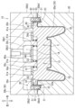
図1~図6は、本発明の第1実施形態を示す。この実施形態は、自動車用シートのフレームであるクッションパン1の製造に本発明を適用した例である。各図中、矢印によりクッションパン1を成形する下型20と上型30が型閉じされた状態における各方向を示している。以下の説明において、方向に関する記述は、この方向を基準として行うものとする。ここで、クッションパン1が、特許請求の範囲の「繊維強化樹脂成形品」に相当する。
Figures 1 to 6 show a first embodiment of the present invention. This embodiment is an example in which the present invention is applied to the manufacture of a cushion pan 1, which is the frame of an automobile seat. In each figure, the arrows indicate the various directions when the
図1~図3に示すように、クッションパン1は、面状の強化繊維体2に樹脂3を含浸させて固化させた板状の成形品である。クッションパン1は、上方から見て後側の2コーナ部が面取りされた略矩形状をしているとともに、左右方向中央部にほぼ平坦なメイン部1Aとメイン部1Aの左右両側に下方に向かって突出する左右一対のサイド部1Bとを備えている。クッションパン1は、成形後に上下逆にして自動車に取付けられたとき、メイン部1Aがクッション材(図示せず)を介して着座乗員の臀部及び大腿部の下面部を支持し、両サイド部1Bがクッション材(図示せず)を介して着座乗員の臀部及び大腿部の側部を支持する。クッションパン1の後側には、着座乗員の背部を支持するシートバック(図示せず)が取付けられる。強化繊維体2は、炭素繊維製の織物を複数枚重ね合わせたものであるが、ガラス繊維製の織物としてもよいし、アラミド繊維製の織物としてもよい。また、樹脂3は熱硬化樹脂であるエポキシ樹脂であるが、不飽和ポリエステル樹脂とすることもできる。
As shown in Figs. 1 to 3, the cushion pan 1 is a plate-shaped molded product obtained by impregnating a planar reinforced
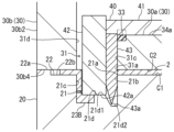
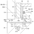
図1~図6に示すように、クッションパン1をRTM工法で成形する成形装置10は、下型20と、下型20に対して閉じられたとき間にキャビティCを形成する上型30と、キャビティCの減圧状態を維持する押圧部材40と、を有する。下型20の上面部には、製品であるクッションパン1の表面形状を成形するキャビティ下面部C1が形成されている。そして、キャビティ下面部C1の外周には下方に向けて凹む横断面が略U字状の溝部21が形成されている。図1及び図2に示すように、溝部21は上方から見て後側の2コーナ部が面取りされた略矩形状の枠状に形成されている。図5によく示されるように、溝部21は上側に開口21aを有している。溝部21の開口21aにおけるキャビティ下面部C1の側の縁部から下方に向かって延びる内側面部21bが形成され、開口21aにおけるキャビティ下面部C1と反対側の縁部から下方に向かって延びる外側面部21cが形成されている。内側面部21bの方が外側面部21cより下方に向かって延びる長さが長く設定されている。内側面部21bの下端部と外側面部21cの下端部とは、屈曲して左右方向に延びる底面部21dによって連結されている。底面部21dは、外側面部21cの側の上底面部21d1と、内側面部21bの側の下底面部21d2と、を有する。上底面部21d1と下底面部21d2は、水平方向に延びている。上底面部21d1には弾性変形が可能なゴム状の部材であり横断面が矩形状の下シール部材23が、その横断面の一部が埋設された形で取付けられている。溝部21の開口21aにおけるキャビティ下面部C1と反対側の縁部から水平方向に型外方向に向かって延びる下パーティング面22が形成されている。下パーティング面22は、型外側に形成され上型30に直接当接する下外パーティング面22aと、溝部21の開口21a側に形成され下外パーティング面22aより若干下側に配置された下内パーティング面22bと、を有する。下内パーティング面22bは強化繊維体2の外周縁部を介在させて上型30に当接する。ここで、下型20と上型30が、それぞれ特許請求の範囲の「第1型」と「第2型」に相当する。また、下シール部材23が、特許請求の範囲の「第1シール部材、シール部材」に相当する。
As shown in Figures 1 to 6, a
図1~図6に示すように、上型30は、本体部30aと、本体部30aの上部に取付けられた枠状部30bと、を備えている。本体部30aの下面部には、製品であるクッションパン1の裏面形状を成形するキャビティ上面部C2が形成されている。また、本体部30aの上面部には、外周面部34aと、外周面部34aより若干下方に向けて凹んだ中央面部34bと、が形成されている。枠状部30bは、水平方向に延びる厚板状の基板部30b1と、基板部30b1の外周縁部から下方に向かって延びる延出部30b2と、を有する。基板部30b1の中央部分には、上方に向かって凹み後述するシリンダ40aを取付けるシリンダ取付孔30b3が設けられている。基板部30b1の下面部と本体部30aの上面部とは複数の円柱状の柱部材30cで連結され、本体部30aと枠状部30bとは一体とされている。本体部30aにおけるキャビティ上面部C2の外周にはキャビティ上面部C2の外周縁部と外周面部34aの外周縁部とを連結して上下に延びる内側面部31cが形成されている。内側面部31cに隣接する外周面部34aには、弾性変形が可能なゴム状の部材であり横断面が矩形状の上シール部材33が、その横断面の一部が埋設された形で取付けられている。枠状部30bにおける延出部30b2の下面部は、水平方向に延びる上パーティング面30b4として形成されている。上パーティング面30b4はキャビティ上面部C2の外周縁部と同一の平面とされている。また、枠状部30bにおける延出部30b2の内側面部31cに対向する面部は、外側面部31dとして形成されている。内側面部31cと外側面部31dとの間は、上下方向に貫通する貫通孔31として形成されている。図1、図2及び図4に示すように、貫通孔31は下型20に対して上型30を閉じたとき、上方から見て溝部21の形状に一致する。図5によく示されるように、貫通孔31は、下側に下開口31aを有している。貫通孔31は下型20に対して上型30を閉じたとき、内側面部31cが溝部21の内側面部21bと面一となり、外側面部31dが溝部21の外側面部21cと面一になる。そして、上パーティング面32は、その型外側部分が下外パーティング面22aに直接当接し、その貫通孔31の下開口31a側部分が強化繊維体2の外周縁部を介在させて下内パーティング面22bに当接する。ここで、上シール部材33が、特許請求の範囲の「第2シール部材、シール部材」に相当する。
As shown in Figures 1 to 6, the
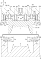
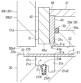
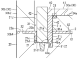
図2~図6に示すように、押圧部材40は、水平方向に延びる板状部41と、板状部41の下面側から下方向に延びる壁状部42が形成されている。板状部41には、上型30の複数の柱部材30cに対応して各柱部材30cが遊嵌する複数の通し孔41aが設けられている。板状部41は、上型30の本体部30aと枠状部30bとの間に上下移動可能に取付けられている。板状部41の下面部と上型30の本体部30aの中央面部34bとの間には各柱部材30cを軸とする圧縮コイルばね44が配設され、板状部41の上面部と上型30における枠状部30bのシリンダ取付孔30b3の上面部との間には油圧シリンダ40aが配設されている。油圧シリンダ40aを作動させると押圧部材40は、上型30に対して上下動するように構成されている。壁状部42は、横断面が長軸の方向を上下方向とする矩形状をしており、型内側の面に刃先43aを下側に備えた板状の切断刃43が取付けられている。刃先43aは、壁状部42の先端側の面である底面部42aより下方に突出している。切断刃43が取付けられた状態の壁状部42の厚みは貫通孔31の幅(図5における左右方向の長さ)より若干小さく設定されている。後述するように、下型20と上型30の間に強化繊維体2を配置して型閉じした状態で、押圧部材40を下降させ切断刃43が取付けられた状態の壁状部42を貫通孔31及び溝部21の中に挿入すると切断刃43の壁状部42と反対側の面は、上型30の内側面部31cと下型20の内側面部21bに摺接して下降する。そして、強化繊維体2の端末部が切断刃43により切断される。壁状部42の底面部42aが下型20の下シール部材23を押圧して圧縮変形させるとともに、板状部41の下面部が上型30の上シール部材33を押圧して圧縮変形させることによってキャビティCと型外との空気の流通を遮断する。このとき、切断された強化繊維体2の端末部の一部が下型20の外側面部21cと壁状部42の切断刃43が取付けられていない面との間の隙間に入り込むように構成されている。また、この状態で切断刃43の刃先43aは、下型20の下底面部21d2の上方に離隔して位置するようになっている。
2 to 6, the pressing
図2~図6に基いて、成形装置10を使用してクッションパン1を製造する方法について説明する。第1工程では、図3、図5及び図6に示すように、下型20のキャビティ下面部C1に強化繊維体2を載置して上型30を閉じると、キャビティC内に強化繊維体2が配置されるとともに、強化繊維体2が溝部21の開口21aを覆った状態となる。このとき、強化繊維体2の端末部分は、下型20の下内パーティング面22bと上型30の上パーティング面30b4とによって挟持される。この状態で、第2工程では、型閉じされた下型20及び上型30に対して油圧シリンダ40aを作動させて上方から押圧部材40を下降させ、壁状部42を上型30の貫通孔31及び下型20の溝部21の中に底面部42aから挿入する。このとき、押圧部材40は、取付けられた切断刃43の壁状部42と反対側の面が上型30の内側面部31cと下型20の内側面部21bに摺接して下降する。そして、強化繊維体2の端末部が切断刃43により切断される。壁状部42の底面部42aが下型20の下シール部材23を押圧して圧縮変形させるとともに、板状部41の下面部が上型30の上シール部材33を押圧して圧縮変形させることによって押圧部材40の下降は停止する。この状態でキャビティCと型外との空気の流通は下シール部材23と上シール部材33によって阻害される。このとき、図4に示すように、切断された強化繊維体2の端末部の溝部21側の部分が下型20の外側面部21cと壁状部42の切断刃43が取付けられていない面との間の隙間に入り込む。また、この状態で切断刃43の刃先43aは、下型20の下底面部21d2の上方に離隔して位置する。
A method for manufacturing a cushion pan 1 using a
次に第3工程では、図2及び図4に示す状態において、キャビティCに連結された図示しない空気吸引装置を作動させてキャビティC内の空気を吸引して減圧状態とする。このとき、圧縮変形された下シール部材23と上シール部材33の働きによって型外からキャビティC内への空気の流入が阻止されるのでキャビティCが減圧状態に保たれる。次に第4工程では、前記空気吸引装置の作動を停止してキャビティC内に液体状態の樹脂3を図示しない注入口より注入して強化繊維体2に含浸させた状態で固化させる。最後に第5工程において、下型20に対して押圧部材40と上型30を上昇させて強化繊維体2に液体状態の樹脂3を含浸させて固化させた成形品であるクッションパン1を脱型する。
Next, in the third step, in the state shown in Figures 2 and 4, an air suction device (not shown) connected to cavity C is operated to suck air from within cavity C and create a reduced pressure state. At this time, the compressed and deformed
以上のように構成される第1実施形態は、以下のような作用効果を奏する。下型20に対し上型30を下降させ型締めした状態で押圧部材40を下降させてキャビティC内に配置された強化繊維体2の端末部をキャビティ下面部C1の外周縁形状に沿って切断することができる。これによって、成形品を脱型した後にトリミングする必要が無いとともに切断するツールにおける刃の摩耗が大きいという問題もない。また、押圧部材40の壁状部42が上型30の貫通孔31及び下型20の溝部21に上方から挿入された状態で下シール部材23と上シール部材33が圧縮変形させられてキャビティC内から型外への空気の流通を阻害する。これによって、第3工程においてキャビティC内の減圧状態を良好に保って液体状態の樹脂3の注入ができ、液体状態の樹脂3が強化繊維体2に含浸するのを促進できる。また、下シール部材23と上シール部材33が圧縮変形可能な弾性体により形成されているので、成形の度ごとに下シール部材23と上シール部材33を交換する必要が無く便宜である。
The first embodiment configured as described above has the following effects. The
図7及び図8は、本発明の第2実施形態を示す。上記第1実施形態との違いは、下シール部材23の代わりに弾性変形が可能な中空の管状体である下シール部材23Aが使用されている点である。上記第1実施形態と共通する構造については同一の符号を付して説明を省略する。下シール部材23Aは、内部空間23A1に図示しない空気供給装置から空気を供給可能に構成された状態で、下型20における溝部21の上底面部21d1から一部が上方に露出するように埋設設置されている。そして、第2工程において壁状部42の底面部42aが当接する前に内部空間23A1に空気が供給されて膨らんだ状態で底面部42aによって押圧変形されるようになっている。これによって、下シール部材23Aは下シール部材23より圧縮変形しやすくなるのでキャビティCと型外の間とのシール性が向上し、キャビティC内の減圧状態をより良好に保って樹脂の注入ができる。ここで、下シール部材23Aが、特許請求の範囲の「第1シール部材、シール部材」に相当する。
7 and 8 show a second embodiment of the present invention. The difference from the first embodiment is that a
図9及び図10は、本発明の第3実施形態を示す。上記第1実施形態との違いは、下シール部材23の代わりに強化繊維体2の帯状体に予め未硬化の樹脂を含浸させたプリプレグが下シール部材23Bとして使用されている点である。上記第1実施形態と共通する構造については同一の符号を付して説明を省略する。下シール部材23Bは、強化繊維体2の帯状体に予め液体状態の未固化の樹脂を含浸させたプリプレグであり、第2工程において、下型20における溝部21の上底面部21d1から一部が上方に露出するように配置されている。そして、壁状部42の底面部42aが下シール部材23Bを押圧変形させた状態でキャビティCと型外の間との空気の流通を抑える。第5工程でクッションパン1を脱型したのち固化した下シール部材23Bは、切断された強化繊維体2の端材とともに廃棄される。これによって、下シール部材23Bは常に新しい予め液体状態の未固化の樹脂を含浸させたプリプレグとすることができるので、キャビティCと型外の間とのシール性が向上し、キャビティC内の減圧状態をより良好に保って樹脂の注入ができる。ここで、下シール部材23Bが、特許請求の範囲の「第1シール部材、シール部材」に相当する。
9 and 10 show the third embodiment of the present invention. The difference from the first embodiment is that a prepreg in which a strip of the reinforced
図11及び図12は、本発明の第4実施形態を示す。上記第1実施形態との違いは、下シール部材23の代わりに加熱によって軟化し冷却によって固化するワックス体が下シール部材23Cとして使用されている点である。上記第1実施形態と共通する構造については同一の符号を付して説明を省略する。下シール部材23Cは、加熱によって軟化し冷却によって固化するワックス体であり、第2工程において、加熱して軟化した状態で、下型20における溝部21の上底面部21d1から一部が上方に露出するように配置されている。そして、壁状部42の底面部42aが下シール部材23Cを押圧変形させた状態でキャビティCと型外の間との空気の流通を抑える。第5工程でクッションパン1を脱型したのち固化した下シール部材23Cは、切断された強化繊維体2の端材とともに廃棄される。これによって、下シール部材23Cは常に新しいワックス体とすることができるので、キャビティCと型外の間とのシール性が向上し、キャビティC内の減圧状態をより良好に保って樹脂の注入ができる。ここで、下シール部材23Cが、特許請求の範囲の「第1シール部材、シール部材」に相当する。
11 and 12 show the fourth embodiment of the present invention. The difference from the first embodiment is that a wax body that is softened by heating and solidified by cooling is used as the lower seal member 23C instead of the
以上、特定の実施形態について説明したが、本発明は、それらの外観、構成に限定されず、本発明の要旨を変更しない範囲で種々の変更、追加、削除が可能である。例えば、次のようなものが挙げられる。 Although specific embodiments have been described above, the present invention is not limited to those appearances and configurations, and various modifications, additions, and deletions are possible without changing the gist of the present invention. For example, the following can be mentioned:
1.上記実施形態においては、第1型を下型20とし、第2型を上型30として上下に開閉するものとしたが、これに関わらず、水平方向に開閉する第1型及び第2型とすることもできる。
1. In the above embodiment, the first mold is the
2.上記実施形態においては、キャビティ下面部C1の外周縁部に溝部21を配設した。しかし、これに関わらず、成形品の中央部分に板厚方向に貫通する孔がある場合には、その孔の外周縁部にも溝部を設けることができる。これによって、成形後に切断するツールを利用して孔をあける必要がなくなる。
2. In the above embodiment, the
3.上記実施形態においては、本発明を自動車のシートに適用したが、飛行機、船、電車等に搭載のシートに適用しても良いし、自動車の内装部品に適用することもできる。 3. In the above embodiment, the present invention is applied to an automobile seat, but it may also be applied to seats installed in airplanes, ships, trains, etc., and may also be applied to interior parts of automobiles.
1 クッションパン(繊維強化樹脂成形品)
2 強化繊維体
3 樹脂
10 成形装置
20 下型(第1型)
21 溝部
23 下シール部材(第1シール部材、シール部材)
23A 下シール部材(第1シール部材、シール部材)
23B 下シール部材(第1シール部材、シール部材)
23C 下シール部材(第1シール部材、シール部材)
30 上型(第2型)
31 貫通孔
33 上シール部材(第2シール部材、シール部材)
40 押圧部材
42 壁状部
43 切断刃
43a 刃先
C キャビティ
C1 キャビティ下面部
C2 キャビティ上面部
1. Cushion pan (fiber reinforced plastic molded product)
2 Reinforced fiber body 3
21
23A Lower seal member (first seal member, seal member)
23B Lower seal member (first seal member, seal member)
23C Lower seal member (first seal member, seal member)
30 Upper type (2nd type)
31 through
40: Pressing member 42: Wall-like portion 43:
Claims (5)
前記第1型には前記キャビティの面の外周縁に沿って延び前記第2型と反対側に向かって凹む横断面が略U字状の溝部が形成されており、
前記第2型には型締め時に前記溝部に対応して延びるとともに型締め方向に貫通する貫通孔が形成されており、
前記押圧部材は、前記第1型及び前記第2型を型締めした状態の前記貫通孔及び前記溝部に対応した形状で前記貫通孔及び前記溝部に外部から挿入されて遊嵌する壁状部が形成されており、
該壁状部には前記溝部の前記キャビティの側の壁面に沿って延び前記溝部の側に刃先を有する切断刃が設けられており、
前記壁状部が前記貫通孔及び前記溝部に挿入された状態で前記押圧部材と前記第2型との間及び前記押圧部材と前記第1型との間には前記キャビティから型外への空気の流通を阻害するシール部材が介在するように構成されており、
前記第1型と前記第2型の間に前記強化繊維体を配置して型締めする第1工程と、
前記貫通孔と前記溝部の中に前記壁状部を挿入して前記切断刃によって前記強化繊維体の端部を切断するとともに前記シール部材によって前記キャビティと型外との間をシールする第2工程と、
前記キャビティ内の空気を吸引して減圧状態とする第3工程と、
前記キャビティ内に液体状態の樹脂を注入して前記強化繊維体に含浸固化させる第4工程と、
前記第1型と前記第2型を開いて繊維強化樹脂成形品を取出す第5工程と、を有しており、
前記押圧部材は、板状部から前記壁状部が垂直方向に延びるように形成されており、
前記シール部材は、前記壁状部と前記溝部の壁面との間に配置されて延びる第1シール部材と、前記板状部と前記第2型との間に配置されて延びる第2シール部材と、で構成され、該第2シール部材は圧縮変形可能な弾性体により形成されており、
前記第2工程において前記第2シール部材が前記押圧部材によって押圧されて圧縮変形することによりシールを行う繊維強化樹脂成形品の製造方法。 A method for producing a fiber-reinforced plastic molded product in which a planar reinforcing fiber body is impregnated and solidified with a resin using a molding device having a first mold and a second mold that form a cavity of a product shape when the molds are closed, and a pressing member that moves in a mold closing direction relative to the first mold and the second mold that are closed,
The first die has a groove portion having a generally U-shaped cross section extending along an outer periphery of a surface of the cavity and recessed toward an opposite side to the second die,
a through hole is formed in the second die, the through hole extending in a direction of clamping the die and corresponding to the groove portion when the die is clamped;
the pressing member is formed with a wall-like portion having a shape corresponding to the through hole and the groove portion in a state in which the first die and the second die are clamped, the wall-like portion being inserted from the outside into the through hole and the groove portion and loosely fitted therein;
The wall portion is provided with a cutting blade that extends along a wall surface of the groove portion on the side of the cavity and has a cutting edge on the side of the groove portion,
a seal member that blocks air from passing through the cavity to the outside of the mold is interposed between the pressing member and the second mold and between the pressing member and the first mold in a state in which the wall-like portion is inserted into the through hole and the groove portion,
A first step of placing the reinforcing fiber body between the first mold and the second mold and clamping the mold;
a second step of inserting the wall-shaped portion into the through hole and the groove portion, cutting the end of the reinforcing fiber body with the cutting blade, and sealing the cavity and the outside of the mold with the sealing member;
a third step of sucking air from the cavity to create a reduced pressure state;
A fourth step of injecting a liquid resin into the cavity to impregnate and solidify the reinforcing fiber body;
A fifth step of opening the first mold and the second mold to remove a fiber reinforced resin molded product,
The pressing member is formed such that the wall portion extends vertically from a plate portion,
the sealing member is composed of a first sealing member disposed between the wall portion and a wall surface of the groove portion and extending therefrom, and a second sealing member disposed between the plate portion and the second die and extending therefrom, the second sealing member being formed of a compressible elastic body;
In the second step, the second seal member is pressed by the pressing member to perform compressive deformation, thereby achieving sealing .
前記第1シール部材が圧縮変形可能な弾性体により形成されており、前記第2工程において前記第1シール部材及び前記第2シール部材が前記押圧部材によって押圧されて圧縮変形することによりシールを行う繊維強化樹脂成形品の製造方法。 In claim 1,
A method for manufacturing a fiber-reinforced resin molded product, wherein the first sealing member is formed of a compressible elastic body, and in the second step, the first sealing member and the second sealing member are pressed by the pressing member to perform sealing by compressive deformation .
2. The method for manufacturing a fiber-reinforced plastic molded product according to claim 1 , wherein the first sealing member is a wax body that is softened by heating and solidified by cooling, and is placed in the groove portion in the heated and softened state in the first step, and is solidified in a compressed state in the second step .
Priority Applications (1)
| Application Number | Priority Date | Filing Date | Title |
|---|---|---|---|
| JP2021026147A JP7552425B2 (en) | 2021-02-22 | 2021-02-22 | Manufacturing method of fiber reinforced plastic molded product |
Applications Claiming Priority (1)
| Application Number | Priority Date | Filing Date | Title |
|---|---|---|---|
| JP2021026147A JP7552425B2 (en) | 2021-02-22 | 2021-02-22 | Manufacturing method of fiber reinforced plastic molded product |
Publications (2)
| Publication Number | Publication Date |
|---|---|
| JP2022127912A JP2022127912A (en) | 2022-09-01 |
| JP7552425B2 true JP7552425B2 (en) | 2024-09-18 |
Family
ID=83060878
Family Applications (1)
| Application Number | Title | Priority Date | Filing Date |
|---|---|---|---|
| JP2021026147A Active JP7552425B2 (en) | 2021-02-22 | 2021-02-22 | Manufacturing method of fiber reinforced plastic molded product |
Country Status (1)
| Country | Link |
|---|---|
| JP (1) | JP7552425B2 (en) |
Families Citing this family (1)
| Publication number | Priority date | Publication date | Assignee | Title |
|---|---|---|---|---|
| JP2024074363A (en) * | 2022-11-21 | 2024-05-31 | トヨタ紡織株式会社 | Manufacturing method of fiber reinforced plastic molded product |
Citations (1)
| Publication number | Priority date | Publication date | Assignee | Title |
|---|---|---|---|---|
| JP2017222142A (en) | 2016-06-17 | 2017-12-21 | 株式会社名機製作所 | Press molding apparatus and press molding method for molded products containing reinforcing fibers and thermoplastic resin |
Family Cites Families (3)
| Publication number | Priority date | Publication date | Assignee | Title |
|---|---|---|---|---|
| US5040962A (en) * | 1989-12-12 | 1991-08-20 | The Dow Chemical Company | Reaction injection molding apparatus with internal frame and shear edge |
| US5182065A (en) * | 1990-04-30 | 1993-01-26 | Ontario Die Company Limited | Method for producing structural injection molded parts using lost motion movement between a mold and surrounding cutting blade |
| US5393474A (en) * | 1993-08-19 | 1995-02-28 | Davidson Textron Inc. | Method for molding a shaped plastic trim panel |
-
2021
- 2021-02-22 JP JP2021026147A patent/JP7552425B2/en active Active
Patent Citations (1)
| Publication number | Priority date | Publication date | Assignee | Title |
|---|---|---|---|---|
| JP2017222142A (en) | 2016-06-17 | 2017-12-21 | 株式会社名機製作所 | Press molding apparatus and press molding method for molded products containing reinforcing fibers and thermoplastic resin |
Also Published As
| Publication number | Publication date |
|---|---|
| JP2022127912A (en) | 2022-09-01 |
Similar Documents
| Publication | Publication Date | Title |
|---|---|---|
| CN102427932B (en) | Manufacturing Composite Parts | |
| WO2014192601A1 (en) | Method and device for manufacturing fiber-reinforced plastic | |
| US6929770B2 (en) | Mandrel-assisted resin transfer molding process employing resin outflow perimeter channel between male and female mold elements | |
| CN103862609B (en) | Sealing device for foam injection mold | |
| EP3342573B1 (en) | Method and apparatus for producing a trim component having a molded rim at an edge thereof | |
| JP7552425B2 (en) | Manufacturing method of fiber reinforced plastic molded product | |
| JP6020512B2 (en) | Manufacturing method of undercover for vehicle | |
| JP2009028939A (en) | RTM molding method | |
| US12059827B2 (en) | Apparatus, mold set, and method for producing metal-resin composite | |
| US20220395885A1 (en) | Mold, apparatus, and method for producing metal-resin composite | |
| JP3755864B2 (en) | Method and apparatus for molding laminated molded body | |
| JP4482440B2 (en) | Plastic molded product | |
| JP7468116B2 (en) | Composite material molding equipment | |
| KR101795582B1 (en) | Manufacturing apparatus of interior for vehicle | |
| JPH10167139A (en) | Motorcycle seat device and method of manufacturing the same | |
| JP2013233680A (en) | Mold and method of producing foamed molded body | |
| JP2019142078A (en) | Manufacturing method of molded structure | |
| KR20040100733A (en) | Die apparatus for interior panel of vehicle and manufacturing method of interior panel using the same | |
| JP7234781B2 (en) | Substrate manufacturing method | |
| KR101687600B1 (en) | Forming device for wallboard of vehicle | |
| JP2021146673A (en) | Method for producing composite molded product | |
| JP2024010737A (en) | Molded structure and method for manufacturing the molded structure | |
| JP2019171718A (en) | Manufacturing method of molded structure and mold | |
| CN110588016B (en) | Forming tool and forming method for composite material integrated joint | |
| JP2019006017A (en) | Molding apparatus and method of molding resin molded article |
Legal Events
| Date | Code | Title | Description |
|---|---|---|---|
| A621 | Written request for application examination |
Free format text: JAPANESE INTERMEDIATE CODE: A621 Effective date: 20230803 |
|
| A131 | Notification of reasons for refusal |
Free format text: JAPANESE INTERMEDIATE CODE: A131 Effective date: 20240604 |
|
| A977 | Report on retrieval |
Free format text: JAPANESE INTERMEDIATE CODE: A971007 Effective date: 20240613 |
|
| A521 | Request for written amendment filed |
Free format text: JAPANESE INTERMEDIATE CODE: A523 Effective date: 20240625 |
|
| TRDD | Decision of grant or rejection written | ||
| A01 | Written decision to grant a patent or to grant a registration (utility model) |
Free format text: JAPANESE INTERMEDIATE CODE: A01 Effective date: 20240806 |
|
| A61 | First payment of annual fees (during grant procedure) |
Free format text: JAPANESE INTERMEDIATE CODE: A61 Effective date: 20240819 |
|
| R150 | Certificate of patent or registration of utility model |
Ref document number: 7552425 Country of ref document: JP Free format text: JAPANESE INTERMEDIATE CODE: R150 |