EP0234341B2 - Perimeter resin feeding of composite structures - Google Patents
Perimeter resin feeding of composite structures Download PDFInfo
- Publication number
- EP0234341B2 EP0234341B2 EP87101406A EP87101406A EP0234341B2 EP 0234341 B2 EP0234341 B2 EP 0234341B2 EP 87101406 A EP87101406 A EP 87101406A EP 87101406 A EP87101406 A EP 87101406A EP 0234341 B2 EP0234341 B2 EP 0234341B2
- Authority
- EP
- European Patent Office
- Prior art keywords
- resin
- mold
- fibrous material
- pieces
- channel
- Prior art date
- Legal status (The legal status is an assumption and is not a legal conclusion. Google has not performed a legal analysis and makes no representation as to the accuracy of the status listed.)
- Expired - Lifetime
Links
Images

Classifications
-
- B—PERFORMING OPERATIONS; TRANSPORTING
- B29—WORKING OF PLASTICS; WORKING OF SUBSTANCES IN A PLASTIC STATE IN GENERAL
- B29C—SHAPING OR JOINING OF PLASTICS; SHAPING OF MATERIAL IN A PLASTIC STATE, NOT OTHERWISE PROVIDED FOR; AFTER-TREATMENT OF THE SHAPED PRODUCTS, e.g. REPAIRING
- B29C43/00—Compression moulding, i.e. applying external pressure to flow the moulding material; Apparatus therefor
- B29C43/02—Compression moulding, i.e. applying external pressure to flow the moulding material; Apparatus therefor of articles of definite length, i.e. discrete articles
- B29C43/18—Compression moulding, i.e. applying external pressure to flow the moulding material; Apparatus therefor of articles of definite length, i.e. discrete articles incorporating preformed parts or layers, e.g. compression moulding around inserts or for coating articles
-
- B—PERFORMING OPERATIONS; TRANSPORTING
- B29—WORKING OF PLASTICS; WORKING OF SUBSTANCES IN A PLASTIC STATE IN GENERAL
- B29C—SHAPING OR JOINING OF PLASTICS; SHAPING OF MATERIAL IN A PLASTIC STATE, NOT OTHERWISE PROVIDED FOR; AFTER-TREATMENT OF THE SHAPED PRODUCTS, e.g. REPAIRING
- B29C70/00—Shaping composites, i.e. plastics material comprising reinforcements, fillers or preformed parts, e.g. inserts
- B29C70/04—Shaping composites, i.e. plastics material comprising reinforcements, fillers or preformed parts, e.g. inserts comprising reinforcements only, e.g. self-reinforcing plastics
- B29C70/28—Shaping operations therefor
- B29C70/40—Shaping or impregnating by compression not applied
- B29C70/42—Shaping or impregnating by compression not applied for producing articles of definite length, i.e. discrete articles
- B29C70/44—Shaping or impregnating by compression not applied for producing articles of definite length, i.e. discrete articles using isostatic pressure, e.g. pressure difference-moulding, vacuum bag-moulding, autoclave-moulding or expanding rubber-moulding
- B29C70/443—Shaping or impregnating by compression not applied for producing articles of definite length, i.e. discrete articles using isostatic pressure, e.g. pressure difference-moulding, vacuum bag-moulding, autoclave-moulding or expanding rubber-moulding and impregnating by vacuum or injection
-
- B—PERFORMING OPERATIONS; TRANSPORTING
- B29—WORKING OF PLASTICS; WORKING OF SUBSTANCES IN A PLASTIC STATE IN GENERAL
- B29C—SHAPING OR JOINING OF PLASTICS; SHAPING OF MATERIAL IN A PLASTIC STATE, NOT OTHERWISE PROVIDED FOR; AFTER-TREATMENT OF THE SHAPED PRODUCTS, e.g. REPAIRING
- B29C33/00—Moulds or cores; Details thereof or accessories therefor
- B29C33/10—Moulds or cores; Details thereof or accessories therefor with incorporated venting means
-
- B—PERFORMING OPERATIONS; TRANSPORTING
- B29—WORKING OF PLASTICS; WORKING OF SUBSTANCES IN A PLASTIC STATE IN GENERAL
- B29C—SHAPING OR JOINING OF PLASTICS; SHAPING OF MATERIAL IN A PLASTIC STATE, NOT OTHERWISE PROVIDED FOR; AFTER-TREATMENT OF THE SHAPED PRODUCTS, e.g. REPAIRING
- B29C43/00—Compression moulding, i.e. applying external pressure to flow the moulding material; Apparatus therefor
- B29C43/32—Component parts, details or accessories; Auxiliary operations
- B29C43/34—Feeding the material to the mould or the compression means
-
- B—PERFORMING OPERATIONS; TRANSPORTING
- B29—WORKING OF PLASTICS; WORKING OF SUBSTANCES IN A PLASTIC STATE IN GENERAL
- B29C—SHAPING OR JOINING OF PLASTICS; SHAPING OF MATERIAL IN A PLASTIC STATE, NOT OTHERWISE PROVIDED FOR; AFTER-TREATMENT OF THE SHAPED PRODUCTS, e.g. REPAIRING
- B29C45/00—Injection moulding, i.e. forcing the required volume of moulding material through a nozzle into a closed mould; Apparatus therefor
- B29C45/14—Injection moulding, i.e. forcing the required volume of moulding material through a nozzle into a closed mould; Apparatus therefor incorporating preformed parts or layers, e.g. injection moulding around inserts or for coating articles
-
- B—PERFORMING OPERATIONS; TRANSPORTING
- B29—WORKING OF PLASTICS; WORKING OF SUBSTANCES IN A PLASTIC STATE IN GENERAL
- B29C—SHAPING OR JOINING OF PLASTICS; SHAPING OF MATERIAL IN A PLASTIC STATE, NOT OTHERWISE PROVIDED FOR; AFTER-TREATMENT OF THE SHAPED PRODUCTS, e.g. REPAIRING
- B29C70/00—Shaping composites, i.e. plastics material comprising reinforcements, fillers or preformed parts, e.g. inserts
- B29C70/04—Shaping composites, i.e. plastics material comprising reinforcements, fillers or preformed parts, e.g. inserts comprising reinforcements only, e.g. self-reinforcing plastics
- B29C70/28—Shaping operations therefor
- B29C70/40—Shaping or impregnating by compression not applied
- B29C70/42—Shaping or impregnating by compression not applied for producing articles of definite length, i.e. discrete articles
- B29C70/46—Shaping or impregnating by compression not applied for producing articles of definite length, i.e. discrete articles using matched moulds, e.g. for deforming sheet moulding compounds [SMC] or prepregs
- B29C70/48—Shaping or impregnating by compression not applied for producing articles of definite length, i.e. discrete articles using matched moulds, e.g. for deforming sheet moulding compounds [SMC] or prepregs and impregnating the reinforcements in the closed mould, e.g. resin transfer moulding [RTM], e.g. by vacuum
-
- B—PERFORMING OPERATIONS; TRANSPORTING
- B29—WORKING OF PLASTICS; WORKING OF SUBSTANCES IN A PLASTIC STATE IN GENERAL
- B29C—SHAPING OR JOINING OF PLASTICS; SHAPING OF MATERIAL IN A PLASTIC STATE, NOT OTHERWISE PROVIDED FOR; AFTER-TREATMENT OF THE SHAPED PRODUCTS, e.g. REPAIRING
- B29C70/00—Shaping composites, i.e. plastics material comprising reinforcements, fillers or preformed parts, e.g. inserts
- B29C70/04—Shaping composites, i.e. plastics material comprising reinforcements, fillers or preformed parts, e.g. inserts comprising reinforcements only, e.g. self-reinforcing plastics
- B29C70/28—Shaping operations therefor
- B29C70/54—Component parts, details or accessories; Auxiliary operations, e.g. feeding or storage of prepregs or SMC after impregnation or during ageing
- B29C70/546—Measures for feeding or distributing the matrix material in the reinforcing structure
- B29C70/548—Measures for feeding or distributing the matrix material in the reinforcing structure using distribution constructions, e.g. channels incorporated in or associated with the mould
-
- B—PERFORMING OPERATIONS; TRANSPORTING
- B29—WORKING OF PLASTICS; WORKING OF SUBSTANCES IN A PLASTIC STATE IN GENERAL
- B29C—SHAPING OR JOINING OF PLASTICS; SHAPING OF MATERIAL IN A PLASTIC STATE, NOT OTHERWISE PROVIDED FOR; AFTER-TREATMENT OF THE SHAPED PRODUCTS, e.g. REPAIRING
- B29C70/00—Shaping composites, i.e. plastics material comprising reinforcements, fillers or preformed parts, e.g. inserts
- B29C70/68—Shaping composites, i.e. plastics material comprising reinforcements, fillers or preformed parts, e.g. inserts by incorporating or moulding on preformed parts, e.g. inserts or layers, e.g. foam blocks
- B29C70/86—Incorporated in coherent impregnated reinforcing layers, e.g. by winding
- B29C70/865—Incorporated in coherent impregnated reinforcing layers, e.g. by winding completely encapsulated
-
- B—PERFORMING OPERATIONS; TRANSPORTING
- B29—WORKING OF PLASTICS; WORKING OF SUBSTANCES IN A PLASTIC STATE IN GENERAL
- B29C—SHAPING OR JOINING OF PLASTICS; SHAPING OF MATERIAL IN A PLASTIC STATE, NOT OTHERWISE PROVIDED FOR; AFTER-TREATMENT OF THE SHAPED PRODUCTS, e.g. REPAIRING
- B29C43/00—Compression moulding, i.e. applying external pressure to flow the moulding material; Apparatus therefor
- B29C43/02—Compression moulding, i.e. applying external pressure to flow the moulding material; Apparatus therefor of articles of definite length, i.e. discrete articles
- B29C43/10—Isostatic pressing, i.e. using non-rigid pressure-exerting members against rigid parts or dies
- B29C43/12—Isostatic pressing, i.e. using non-rigid pressure-exerting members against rigid parts or dies using bags surrounding the moulding material or using membranes contacting the moulding material
Definitions
- the invention relates to a method of forming a fiber-reinforced structure.
- the channel through which the resin is injected into the said fibrous material extends around the perimeter of the fiber-reinforced structure to be formed as a minigroove for linear gating, the cross section of which corresponds to the wall thickness of the structure to be formed.
- Air is vented during resin injection through a vent arranged centrally in relation to the perimeter.
- Secondary vacuum sinks may be provided at the edge of the mold avoiding entering of air bubbles.
- the object of the invention is to provide a method of forming a solid fiber-reinforced structure which permits forming large structures whithin a short time using relatively low input pressure for the injection of the resin.
- This object is obtained by a method of forming a fiber-reinforced structure comprising the steps of:
- said fiber-reinforced structure comprises foam disposed within said mold.
- the frame may include front post 12, center post 14 and rear post 16.
- the frame is designed to provide door openings 18 and 20 and a window opening 22.
- an automobile structure which forms part of a door frame for an automobile.
- the frame may include various joints, curved surfaces and areas of irregular cross sections.
- Asingular integral cured structure was formed from several prelocated, but unimpregnated, fiber pieces which were subsequently injected with resin and suitably molded and cured.
- the structure included a hollow area extending thereto.
- the present invention includes many of the steps illustrated in the copening patent application. In the present invention, however, the structure 10 is much larger than the structure illustrated in the copending application.
- a source of resin is connected to a plurality of inlet ports 24 to impregnate the fiber material 26 which ultimately forms the solid structures.
- a plurality of channels or reservoirs 28, 30, 32, 34 and 36 are provided between the resin inlet ports 24 and the fibrous material 26, there are provided a plurality of channels or reservoirs 28, 30, 32, 34 and 36.
- the grooves or reservoirs are disposed adjacent the fibrous material 26. Channels or reservoirs receive the resin from the ports 24.
- the fibrous material 26 is impregnated with the resin.
- a plurality of air vents 38 is provided to vent the air as the resin is injected into the fibrous material. Vent groove 48 is disposed about the periphery of the frame, vent groove 50 is disposed at the center post 14, and vent groove 52 is disposed at the end post 16 to facilitate the venting of the air to the vent ports 38.
- Fig. 1 for purpose of explanation, the pieces are not illustrated. However, the various channels for reservoirs for receiving the resin are actually part of the mold involved, and may be in the upper or lower mold piece. Likewise, the air vent grooves also form part of the mold involved.
- a single integrally cured structure then is developed from several prelocated fibrous pieces, such as pieces 54 and 56.
- the piece 54 is placed within the inner wall of the piece 58 of a mold 60 and is lapped over the piece 56.
- the piece 56 is disposed on the inner wall of the lower piece 62 of the mold 60.
- a hollow area 64 extends through the structure, as in the aforementioned copending patent application.
- an inflatible bladder 66 Prior to closing the mold 60, an inflatible bladder 66, is inserted between pieces 54 and 56.
- the bladder may comprise a plurality of pieces cut to suitable shapes and sizes, corresponding to the shape and size of the structure to be formed.
- a curing operation is performed. Depending upon the chosen resin, the curing could be done either at room temperature or an elevated temperature, which involves heating the fibrous material with the resin while under pressure. The curing completes the formation of the structure 10, which is the side frame illustrated in Fig. 1.
- a sandwich panel structure is formed between a mold 72, which includes upper and lower pieces 74 and 76.
- the sandwich panel structure includes urethane material 78 at a core surrounded by fiberglass or other fibrous material skins 80.
- a channel or reservoir 82 is disposed about the periphery of the main panel structures. Resin is injected to the skin 80 from resin inlet ports to the reservoir 82 to the skin 80.
- resin is injected completely around the panel or structure edge to allow molding of the complete structural edging as well as the sandwich skin.
- the skins were .035 inches (0.9 mm) thick fiberglass, which is relatively thin with to respect to RTM.
- the perimeter resin feeding permitted such a thin skin to be completely impregnated.
- An air vent 84 disposed toward the center of the panel is centrally disposed.
- the single air vent 84 is relatively close to all the inlet resin ports 83. This permits relatively fast injection of the resin under relatively low pressure.
- the vent port 84 extends completely through the foam core as illustrated by the dotted lines.
Landscapes
- Engineering & Computer Science (AREA)
- Mechanical Engineering (AREA)
- Chemical & Material Sciences (AREA)
- Composite Materials (AREA)
- Manufacturing & Machinery (AREA)
- Casting Or Compression Moulding Of Plastics Or The Like (AREA)
- Moulds For Moulding Plastics Or The Like (AREA)
- Injection Moulding Of Plastics Or The Like (AREA)
- Moulding By Coating Moulds (AREA)
Description
- The invention relates to a method of forming a fiber-reinforced structure.
- The publications Modern Plastics International, Feb. 1981, p. 42 and Plastverarbeiter, 32. Jahrgang 1981, Nr. 2, p. 186,188, describe a method offorming a fiber-reinforced structure wherein a mold is provided having a plurality of inlet ports connected to a source of resin and upper and lower pieces with one of said pieces including one channel for receiving resin, fibrous material is placed along the inner walls of said upper and lower pieces adjacent said channel, resin is injected through said inlet ports and said channel into said fibrous material, and said resin is cured to form said fiber-reinforced structure.
- According to such a method known from the above publications the channel through which the resin is injected into the said fibrous material extends around the perimeter of the fiber-reinforced structure to be formed as a minigroove for linear gating, the cross section of which corresponds to the wall thickness of the structure to be formed. Air is vented during resin injection through a vent arranged centrally in relation to the perimeter. Secondary vacuum sinks may be provided at the edge of the mold avoiding entering of air bubbles.
- As the flow resistance for the resin is high in the minigroove which cannot act as a resin reservoir a relatively high injection pressure is required to inject resin, especially if large structures are to be formed.
- The object of the invention is to provide a method of forming a solid fiber-reinforced structure which permits forming large structures whithin a short time using relatively low input pressure for the injection of the resin.
- This object is obtained by a method of forming a fiber-reinforced structure comprising the steps of:
- a) providing a mold having upper and lower pieces with one of said pieces including at least one channel into which open a plurality of inlet ports connected to a source of resin, wherein a second channel is provided in one of said mold pieces to vent air as said resin is being injected,
- b) placing fibrous material along the innerwalls of said upper and lower pieces adjacent said channel(s) and placing an inflatable member between said fibrous material within said mold, closing said mold and inflating said inflatable member,
- c) injecting resin through said inlet ports and said channel (s), which act(s) as a reservoirfor receiving the resin, into said fibrous material and
- d) curing said resin to form a reinforced hollow structure.
- Advantageously, said fiber-reinforced structure comprises foam disposed within said mold.
- Embodiments of the invention are described in the following by means of drawings.
- Fig. 1 is a side view, partly broken away, of an automotive side frame structure, of the type which may be formed using the present invention;
- Fig. 2 is a cross-sectional view, taken along lines 2-2 of Fig. 1, including upper and lower molds not illustrated in Fig. 1;
- Fig. 3 is a cross-sectional view of the part formed, as illustrated in Fig. 2;
- Fig. 4 is a cross-sectional view of a sandwich panel structure.
- Referring to Fig. 1, an automotive frame 10 is illustrated. The frame may include
front post 12,center post 14 and rear post 16. - The frame is designed to provide
door openings - In the copending European application 86108600.7/0 212 140 a portion of an automobile structure is illustrated which forms part of a door frame for an automobile. The frame may include various joints, curved surfaces and areas of irregular cross sections. Asingular integral cured structure was formed from several prelocated, but unimpregnated, fiber pieces which were subsequently injected with resin and suitably molded and cured. The structure included a hollow area extending thereto. The present invention includes many of the steps illustrated in the copening patent application. In the present invention, however, the structure 10 is much larger than the structure illustrated in the copending application.
- Because of the relatively large structure involved in the present application, if a single source of resin was used to impregnate the structure 10, a relatively long time would be involved to complete the impregnation of a single structure. Also, a relatively high amount of pressure would be required to inject the resin. High input pressures may collapse the inflatible bag used or may displace the fabric material.
- Referring again to Fig. 1, along with Figs. 2 and 3, a source of resin is connected to a plurality of
inlet ports 24 to impregnate thefiber material 26 which ultimately forms the solid structures. Between theresin inlet ports 24 and thefibrous material 26, there are provided a plurality of channels orreservoirs fibrous material 26. Channels or reservoirs receive the resin from theports 24. When the resin is applied under pressure, thefibrous material 26 is impregnated with the resin. A plurality ofair vents 38 is provided to vent the air as the resin is injected into the fibrous material.Vent groove 48 is disposed about the periphery of the frame,vent groove 50 is disposed at thecenter post 14, and vent groove 52 is disposed at the end post 16 to facilitate the venting of the air to thevent ports 38. - In Fig. 1, for purpose of explanation, the pieces are not illustrated. However, the various channels for reservoirs for receiving the resin are actually part of the mold involved, and may be in the upper or lower mold piece. Likewise, the air vent grooves also form part of the mold involved.
- Referring to Figs. 2 and 3, a single integrally cured structure then is developed from several prelocated fibrous pieces, such as
pieces piece 54 is placed within the inner wall of thepiece 58 of amold 60 and is lapped over thepiece 56. Thepiece 56 is disposed on the inner wall of thelower piece 62 of themold 60. Ahollow area 64 extends through the structure, as in the aforementioned copending patent application. - Prior to closing the
mold 60, aninflatible bladder 66, is inserted betweenpieces - Air, or other suitable gas from a pressurized source, is applied through a
conduit 68 into theinflatible bladder 66 causing it to inflate to force it against thefibrous pieces - With the
mold 60 closed, resin under pressure is forced through theinlet ports 24 into the various reservoirs or channels into the fibrous material. Air is vented from the fibrous material fromports 38 as the resin is being injected to insure that there are no voids in the fibrous material. - Following are steps for impregnating the fibrous material with resin, a curing operation is performed. Depending upon the chosen resin, the curing could be done either at room temperature or an elevated temperature, which involves heating the fibrous material with the resin while under pressure. The curing completes the formation of the structure 10, which is the side frame illustrated in Fig. 1.
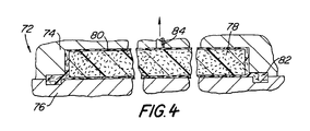
- Referring to Fig. 4, a sandwich panel structure is formed between a
mold 72, which includes upper andlower pieces urethane material 78 at a core surrounded by fiberglass or otherfibrous material skins 80. A channel orreservoir 82 is disposed about the periphery of the main panel structures. Resin is injected to theskin 80 from resin inlet ports to thereservoir 82 to theskin 80. - It is noted that resin is injected completely around the panel or structure edge to allow molding of the complete structural edging as well as the sandwich skin. In one embodiment of the invention, the skins were .035 inches (0.9 mm) thick fiberglass, which is relatively thin with to respect to RTM. The perimeter resin feeding permitted such a thin skin to be completely impregnated.
- An
air vent 84 disposed toward the center of the panel is centrally disposed. Thesingle air vent 84 is relatively close to all the inlet resin ports 83. This permits relatively fast injection of the resin under relatively low pressure. Thevent port 84 extends completely through the foam core as illustrated by the dotted lines.
Claims (2)
Applications Claiming Priority (2)
| Application Number | Priority Date | Filing Date | Title |
|---|---|---|---|
| US833304 | 1986-02-26 | ||
| US06/833,304 US4740346A (en) | 1986-02-26 | 1986-02-26 | Perimeter resin feeding of composite structures |
Publications (3)
| Publication Number | Publication Date |
|---|---|
| EP0234341A1 EP0234341A1 (en) | 1987-09-02 |
| EP0234341B1 EP0234341B1 (en) | 1990-08-22 |
| EP0234341B2 true EP0234341B2 (en) | 1993-01-27 |
Family
ID=25264037
Family Applications (1)
| Application Number | Title | Priority Date | Filing Date |
|---|---|---|---|
| EP87101406A Expired - Lifetime EP0234341B2 (en) | 1986-02-26 | 1987-02-03 | Perimeter resin feeding of composite structures |
Country Status (10)
| Country | Link |
|---|---|
| US (1) | US4740346A (en) |
| EP (1) | EP0234341B2 (en) |
| JP (1) | JPS62282912A (en) |
| KR (1) | KR910005205B1 (en) |
| CN (1) | CN1007886B (en) |
| AU (1) | AU592154B2 (en) |
| BR (1) | BR8700858A (en) |
| CA (1) | CA1279168C (en) |
| DE (1) | DE3764375D1 (en) |
| MX (1) | MX171210B (en) |
Families Citing this family (64)
| Publication number | Priority date | Publication date | Assignee | Title |
|---|---|---|---|---|
| US5000990A (en) * | 1985-08-22 | 1991-03-19 | The Budd Company | One piece molded composite part and method of manufacture |
| US4863771A (en) * | 1985-08-22 | 1989-09-05 | The Budd Company | Hollow fiber reinforced structure and method of making same |
| US4889355A (en) * | 1987-11-20 | 1989-12-26 | Trimble Brent J | Composite bicycle frames and methods of making same |
| US4986949A (en) * | 1986-05-12 | 1991-01-22 | Trimble Brent J | Method of making composite bicycle frames |
| US4902458A (en) * | 1987-05-12 | 1990-02-20 | Trimble Brent J | Method of molding composite bicycle frames |
| EP0295758B1 (en) * | 1987-06-15 | 1991-11-21 | The Budd Company | Method for forming a fiber reinforced structure |
| US4873044A (en) * | 1987-12-21 | 1989-10-10 | Shell Oil Company | Method and apparatus for reduction of mold cycle time |
| GB8806299D0 (en) * | 1988-03-17 | 1988-04-13 | Glynwed Consumer & Building | Process of manufacturing thin-walled plastics moulding |
| WO1989009686A1 (en) * | 1988-04-05 | 1989-10-19 | 3-D Composites Limited | Method of injecting a resin into fibres within a mould |
| US4965030A (en) * | 1988-06-15 | 1990-10-23 | Therma-Tru Corp. | Method of forming a compression molded door assembly |
| JPH0276711A (en) * | 1988-09-14 | 1990-03-16 | Ebara Corp | Method for molding impeller of centrifugal hydraulic machinery and mold used therefor |
| US5258159A (en) * | 1990-05-02 | 1993-11-02 | The Budd Company | Process for making a fiber reinforced fuel tank |
| US5344038A (en) * | 1988-10-14 | 1994-09-06 | The Budd Company | Composite fuel tank |
| JP2895841B2 (en) * | 1988-12-27 | 1999-05-24 | 住友化学工業株式会社 | Method for producing synthetic resin laminate having skin material and mold for molding synthetic resin used in this method |
| US5078417A (en) * | 1989-07-19 | 1992-01-07 | Cycle Composites, Inc. | All terrain cycle fork with fiber reinforced resin blades and crown and method of making same |
| US5016895A (en) * | 1989-07-19 | 1991-05-21 | Cycle Composites, Inc. | Cycle fork with fiber reinforced resin blades and crown and method of making same |
| US5484277A (en) * | 1989-12-26 | 1996-01-16 | Mcdonnell Douglas Corporation | Mandreless molding system |
| US5039465A (en) * | 1990-04-24 | 1991-08-13 | The Budd Company | Method and apparatus for forming fiber reinforced plastic preforms from a wet slurry |
| JPH0717379B2 (en) * | 1990-06-07 | 1995-03-01 | 日本研磨材工業株式会社 | Molten zirconia refractory material excellent in high temperature heat resistance and corrosion resistance, its manufacturing method, and continuous casting nozzle |
| US5156786A (en) * | 1990-07-02 | 1992-10-20 | Hudson Products Corporation | Method for manufacuring fan blades |
| SE9003652D0 (en) * | 1990-11-15 | 1990-11-15 | Astra Ab | NEW HETEROCYCLIC COMPOUNDS |
| US5194212A (en) * | 1990-12-18 | 1993-03-16 | Ford Motor Company | Method of manufacturing a fiber-reinforced structure having a hollow blow-molding core |
| JPH0763980B2 (en) * | 1991-03-13 | 1995-07-12 | 河西工業株式会社 | Method and apparatus for molding laminated molded body |
| US5685956A (en) * | 1992-05-12 | 1997-11-11 | The Budd Company | Method and apparatus for binding fibers in a fiber reinforced preform |
| US5820801A (en) * | 1992-05-12 | 1998-10-13 | The Budd Company | Reinforced thermoplastic molding technique method |
| US5286326A (en) * | 1992-05-12 | 1994-02-15 | The Budd Company | Method for binding fibers in a fiber reinforced preform using an electromagnetic field to melt binding fibers |
| JPH07195400A (en) * | 1993-12-28 | 1995-08-01 | Mitsubishi Chem Basf Co Ltd | Method for forming foam with skin |
| WO1996007533A1 (en) * | 1994-09-02 | 1996-03-14 | Lee Q Wayne | Method of making composite product of tubular structure using clamshell mold |
| GB2299269A (en) * | 1995-03-25 | 1996-10-02 | Autosigns Ltd | Advertising frame |
| US5709893A (en) * | 1995-06-06 | 1998-01-20 | The Boeing Company | Breathable tooling for forming parts from volatile-emitting composite materials |
| US5686038A (en) * | 1995-06-06 | 1997-11-11 | The Boeing Company | Resin transfer molding of composite materials that emit volatiles during processing |
| US5658509A (en) * | 1995-11-06 | 1997-08-19 | Ford Motor Company | Method for forming a recyclable seal on an automotive climate control system door |
| US6024712A (en) * | 1995-12-28 | 2000-02-15 | Royce Medical Company | Orthopaedic devices with plastic injection molded onto fabric |
| US5741450A (en) * | 1996-01-16 | 1998-04-21 | Hudson Products Corporation | Method of and apparatus for molding a hollow fan blade |
| US5762352A (en) * | 1996-03-15 | 1998-06-09 | Lee; Kyu-Wang | Bicycle fork having a fiber reinforced steerer tube and fiber reinforced crown and blades and method of making same |
| CN1060716C (en) * | 1996-04-23 | 2001-01-17 | 于宾 | Shaping method for fiber reinforced plastic product and its mould |
| US5795443A (en) * | 1997-03-13 | 1998-08-18 | The Budd Company | Apparatus for controlling fiber depositions in slurry preforms |
| US5814256A (en) * | 1997-03-20 | 1998-09-29 | The Budd Company | Process of producing preforms containing light weight filler particles |
| US5972169A (en) * | 1998-01-15 | 1999-10-26 | The Budd Company | Slurry preform system |
| US5967592A (en) * | 1998-03-23 | 1999-10-19 | The Budd Company | Hollow FRP bumper |
| WO2000018566A1 (en) * | 1998-09-30 | 2000-04-06 | Toray Industries, Inc. | Hollow structure of fiber-reinforced resin and method of manufacturing the same |
| AU3819801A (en) | 2000-02-15 | 2001-08-27 | Royce Medical Co | Molded orthopaedic devices |
| GB0020355D0 (en) * | 2000-08-18 | 2000-10-04 | Coniston Holdings Ltd | Moulding methods |
| WO2005077632A1 (en) * | 2004-02-17 | 2005-08-25 | Toray Industries, Inc. | Rtm molding method and device |
| US7416401B2 (en) * | 2005-06-13 | 2008-08-26 | The Boeing Company | Lightweight composite fairing bar and method for manufacturing the same |
| DE102007015909A1 (en) * | 2007-04-02 | 2008-10-09 | Mt Aerospace Ag | Process for producing fiber-reinforced hollow bodies |
| US8834782B2 (en) * | 2007-08-07 | 2014-09-16 | William L. Rodman | Composite structures and methods of making same |
| WO2010039547A2 (en) | 2008-09-23 | 2010-04-08 | Invision Technology, Llc | Reinforced internal composite structures |
| US8087719B2 (en) | 2010-05-20 | 2012-01-03 | Ford Global Technologies | Sandwich panel |
| DE102011003626B4 (en) * | 2011-02-04 | 2016-07-28 | Bayerische Motoren Werke Aktiengesellschaft | Method for producing a fiber composite component |
| US8968617B2 (en) * | 2012-11-12 | 2015-03-03 | Spirit Aerosystems, Inc. | Thermo-rheological fluid valve for resin infusion |
| US20140255646A1 (en) * | 2013-03-08 | 2014-09-11 | The Boeing Company | Forming Composite Features Using Steered Discontinuous Fiber Pre-Preg |
| CN103213289A (en) * | 2013-04-16 | 2013-07-24 | 江苏奥新新能源汽车有限公司 | Molding technology for composite material product |
| DE102013218205A1 (en) * | 2013-09-11 | 2015-03-26 | Bayerische Motoren Werke Aktiengesellschaft | Method for additionally reinforcing a fiber-reinforced structural component |
| DE102014224040A1 (en) * | 2014-11-25 | 2016-05-25 | Bayerische Motoren Werke Aktiengesellschaft | Process for producing a structural component group and structural component group |
| DE102016218076A1 (en) | 2016-09-21 | 2018-03-22 | Bayerische Motoren Werke Aktiengesellschaft | RTM tool with resin injection system |
| DE102016218650A1 (en) | 2016-09-28 | 2018-03-29 | Bayerische Motoren Werke Aktiengesellschaft | RTM tool for avoiding fiber flooding in the RTM process through optimized flow channel cross-sections |
| DE102016219137A1 (en) | 2016-10-04 | 2018-04-05 | Bayerische Motoren Werke Aktiengesellschaft | Process for producing a fiber composite component with lap joint or local reinforcement |
| EP3562654A4 (en) * | 2016-12-27 | 2020-07-29 | Continental Structural Plastics, Inc. | Continuous channel resin transfer molding with rapid cycle time |
| CN108340598A (en) * | 2018-01-11 | 2018-07-31 | 上海晋飞碳纤科技股份有限公司 | Glass/molding process of PP complex fabric cloth assisted RTMs and molding die |
| WO2019167118A1 (en) * | 2018-02-27 | 2019-09-06 | 日立ジョンソンコントロールズ空調株式会社 | Manufacturing method and manufacturing mold for air conditioner |
| CN110573265B (en) * | 2018-03-28 | 2021-07-16 | 株式会社埃纳科技 | Coating device and coating method |
| CN110001085B (en) * | 2019-03-29 | 2021-01-08 | 江苏恒神股份有限公司 | RTM (resin transfer molding) process one-mold two-cavity preparation method for composite fairing |
| CN114083746A (en) * | 2020-08-24 | 2022-02-25 | 上海神奕医疗科技有限公司 | Packaging device, packaging method, pulse generator and implantable medical device |
Family Cites Families (13)
| Publication number | Priority date | Publication date | Assignee | Title |
|---|---|---|---|---|
| US2859936A (en) * | 1954-03-03 | 1958-11-11 | Cincinnati Testing & Res Lab | Compressor blade and method of forming same |
| US3137898A (en) * | 1960-09-19 | 1964-06-23 | Structural Fibers | Apparatus for the manufacture of fiberreinforced plastic tanks |
| GB1024582A (en) * | 1961-07-05 | 1966-03-30 | Rodgers William | A method of manufacturing a synthetic resin moulding reinforced with fibrous material |
| US3340119A (en) * | 1963-07-08 | 1967-09-05 | Structural Fibers | Method of making molided cylinders |
| US3626051A (en) * | 1969-09-19 | 1971-12-07 | James P Liautaud | Injection molding encapsulation of paper-wound flyback transformers and the like |
| US3978186A (en) * | 1974-11-25 | 1976-08-31 | Beatrice Foods Co. | Method for making a partitioned container |
| DE2861443D1 (en) * | 1977-08-05 | 1982-02-11 | Walter Schwarz | Method and apparatus for making a shaped body from reinforced plastic |
| JPS5438384A (en) * | 1977-08-31 | 1979-03-22 | Yamaha Motor Co Ltd | Fiber reinforced plastics molding |
| SE427913B (en) * | 1981-04-14 | 1983-05-24 | Cougar Sa | PROCEDURAL APPLICATION FOR THE MANUFACTURING OF A VEHICLE OR SIMILAR INTENDED WHEEL CONSTRUCTION OF PLASTIC MATERIAL |
| US4521354A (en) * | 1982-03-25 | 1985-06-04 | The Boeing Company | Method and mold for fabricating an aerodynamic airframe structure |
| US4493808A (en) * | 1982-06-04 | 1985-01-15 | The Singer Company | Method of molding a sewing machine frame of fiber reinforced composition |
| US4560523A (en) * | 1984-04-30 | 1985-12-24 | A&M Engineered Composites Corporation | Intrusion molding process for forming composite structures |
| DE3670788D1 (en) * | 1985-08-22 | 1990-06-07 | Budd Co | METHOD FOR PRODUCING A HOLLOW FIBER REINFORCED ITEM. |
-
1986
- 1986-02-26 US US06/833,304 patent/US4740346A/en not_active Expired - Lifetime
-
1987
- 1987-02-03 EP EP87101406A patent/EP0234341B2/en not_active Expired - Lifetime
- 1987-02-03 DE DE8787101406T patent/DE3764375D1/en not_active Expired - Fee Related
- 1987-02-10 MX MX005194A patent/MX171210B/en unknown
- 1987-02-11 CA CA000529498A patent/CA1279168C/en not_active Expired - Fee Related
- 1987-02-19 AU AU69060/87A patent/AU592154B2/en not_active Ceased
- 1987-02-19 JP JP62036848A patent/JPS62282912A/en active Granted
- 1987-02-24 KR KR1019870001543A patent/KR910005205B1/en not_active IP Right Cessation
- 1987-02-24 BR BR8700858A patent/BR8700858A/en not_active IP Right Cessation
- 1987-02-25 CN CN87100813A patent/CN1007886B/en not_active Expired
Also Published As
| Publication number | Publication date |
|---|---|
| CN1007886B (en) | 1990-05-09 |
| AU592154B2 (en) | 1990-01-04 |
| BR8700858A (en) | 1987-12-22 |
| EP0234341B1 (en) | 1990-08-22 |
| JPS62282912A (en) | 1987-12-08 |
| CA1279168C (en) | 1991-01-22 |
| EP0234341A1 (en) | 1987-09-02 |
| DE3764375D1 (en) | 1990-09-27 |
| US4740346A (en) | 1988-04-26 |
| KR910005205B1 (en) | 1991-07-23 |
| JPH0375017B2 (en) | 1991-11-28 |
| CN87100813A (en) | 1987-09-16 |
| KR870007774A (en) | 1987-09-21 |
| MX171210B (en) | 1993-10-08 |
| AU6906087A (en) | 1987-08-27 |
Similar Documents
| Publication | Publication Date | Title |
|---|---|---|
| EP0234341B2 (en) | Perimeter resin feeding of composite structures | |
| US4724115A (en) | Method of forming composite structures having sections extending in different diections | |
| US5304339A (en) | Method for manufacturing a large-sized object of fiber reinforced synthetic resin | |
| US5087193A (en) | Apparatus for forming a composite article | |
| JP3040490B2 (en) | Apparatus and method for producing large-area components by RTM method | |
| US4863771A (en) | Hollow fiber reinforced structure and method of making same | |
| US6406659B1 (en) | Composite molding method and apparatus | |
| US7939001B2 (en) | Method and apparatus for producing fibre composite mouldings by means of vacuum infusion | |
| US5045251A (en) | Method of resin transfer molding a composite article | |
| CA1264908A (en) | Hollow fiber reinforced structure and method of making same | |
| EP0426317A2 (en) | A resin transfer moulding preform and a method of making the preform | |
| US4911876A (en) | Method of forming an integral fiber reinforced structure | |
| KR20060134105A (en) | Rtm molding method and device | |
| KR20150079900A (en) | Mold, control means, method and installation for producing a preferably fiber-reinforced plastic component | |
| US20120018919A1 (en) | Mold for manufacture of fiber composite parts and method of manufacture of fiber composite parts with such a mold | |
| DE10253100A1 (en) | Resin transfer molding process for production of composite plastic products employs a foam core with internal channels for venting of trapped air | |
| JP2002192535A (en) | Method for rtm molding | |
| JP7443717B2 (en) | Composite material molding method and composite material molding device | |
| US11584096B2 (en) | Method for producing a vehicle composite component | |
| JP7552425B2 (en) | Manufacturing method of fiber reinforced plastic molded product | |
| JP7252021B2 (en) | Resin injection molded product and its manufacturing method | |
| EP0295758A1 (en) | Method for forming a fiber reinforced structure | |
| JP2767147B2 (en) | Manufacturing method of skin integral foam | |
| CA1186880A (en) | Method of making a racket frame | |
| JPH04332627A (en) | Device for forming composite material |
Legal Events
| Date | Code | Title | Description |
|---|---|---|---|
| PUAI | Public reference made under article 153(3) epc to a published international application that has entered the european phase |
Free format text: ORIGINAL CODE: 0009012 |
|
| AK | Designated contracting states |
Kind code of ref document: A1 Designated state(s): DE FR GB NL SE |
|
| 17P | Request for examination filed |
Effective date: 19870930 |
|
| 17Q | First examination report despatched |
Effective date: 19880530 |
|
| GRAA | (expected) grant |
Free format text: ORIGINAL CODE: 0009210 |
|
| AK | Designated contracting states |
Kind code of ref document: B1 Designated state(s): DE FR GB NL SE |
|
| REF | Corresponds to: |
Ref document number: 3764375 Country of ref document: DE Date of ref document: 19900927 |
|
| ET | Fr: translation filed | ||
| PLBI | Opposition filed |
Free format text: ORIGINAL CODE: 0009260 |
|
| 26 | Opposition filed |
Opponent name: BASF AKTIENGESELLSCHAFT, LUDWIGSHAFEN Effective date: 19910518 |
|
| NLR1 | Nl: opposition has been filed with the epo |
Opponent name: BASF AKTIENGESELLSCHAFT. |
|
| PGFP | Annual fee paid to national office [announced via postgrant information from national office to epo] |
Ref country code: FR Payment date: 19911227 Year of fee payment: 6 |
|
| PGFP | Annual fee paid to national office [announced via postgrant information from national office to epo] |
Ref country code: GB Payment date: 19920120 Year of fee payment: 6 |
|
| PGFP | Annual fee paid to national office [announced via postgrant information from national office to epo] |
Ref country code: SE Payment date: 19920124 Year of fee payment: 6 |
|
| PGFP | Annual fee paid to national office [announced via postgrant information from national office to epo] |
Ref country code: DE Payment date: 19920226 Year of fee payment: 6 |
|
| PGFP | Annual fee paid to national office [announced via postgrant information from national office to epo] |
Ref country code: NL Payment date: 19920229 Year of fee payment: 6 |
|
| PUAH | Patent maintained in amended form |
Free format text: ORIGINAL CODE: 0009272 |
|
| STAA | Information on the status of an ep patent application or granted ep patent |
Free format text: STATUS: PATENT MAINTAINED AS AMENDED |
|
| 27A | Patent maintained in amended form |
Effective date: 19930127 |
|
| AK | Designated contracting states |
Kind code of ref document: B2 Designated state(s): DE FR GB NL SE |
|
| PG25 | Lapsed in a contracting state [announced via postgrant information from national office to epo] |
Ref country code: NL Effective date: 19930127 |
|
| PG25 | Lapsed in a contracting state [announced via postgrant information from national office to epo] |
Ref country code: GB Effective date: 19930203 |
|
| PG25 | Lapsed in a contracting state [announced via postgrant information from national office to epo] |
Ref country code: SE Effective date: 19930204 |
|
| NLR2 | Nl: decision of opposition | ||
| EN3 | Fr: translation not filed ** decision concerning opposition | ||
| PG25 | Lapsed in a contracting state [announced via postgrant information from national office to epo] |
Ref country code: FR Effective date: 19930618 |
|
| NLV1 | Nl: lapsed or annulled due to failure to fulfill the requirements of art. 29p and 29m of the patents act | ||
| GBPC | Gb: european patent ceased through non-payment of renewal fee |
Effective date: 19930203 |
|
| PG25 | Lapsed in a contracting state [announced via postgrant information from national office to epo] |
Ref country code: DE Effective date: 19931103 |
|
| REG | Reference to a national code |
Ref country code: FR Ref legal event code: ST |
|
| EUG | Se: european patent has lapsed |
Ref document number: 87101406.4 Effective date: 19930912 |