JP7549335B2 - Crushing Equipment - Google Patents
Crushing Equipment Download PDFInfo
- Publication number
- JP7549335B2 JP7549335B2 JP2020182719A JP2020182719A JP7549335B2 JP 7549335 B2 JP7549335 B2 JP 7549335B2 JP 2020182719 A JP2020182719 A JP 2020182719A JP 2020182719 A JP2020182719 A JP 2020182719A JP 7549335 B2 JP7549335 B2 JP 7549335B2
- Authority
- JP
- Japan
- Prior art keywords
- crushing
- container holding
- rotation
- container
- main body
- Prior art date
- Legal status (The legal status is an assumption and is not a legal conclusion. Google has not performed a legal analysis and makes no representation as to the accuracy of the status listed.)
- Active
Links
- 230000000452 restraining effect Effects 0.000 description 12
- 230000008878 coupling Effects 0.000 description 7
- 238000010168 coupling process Methods 0.000 description 7
- 238000005859 coupling reaction Methods 0.000 description 7
- 230000014759 maintenance of location Effects 0.000 description 6
- 244000005700 microbiome Species 0.000 description 3
- IJGRMHOSHXDMSA-UHFFFAOYSA-N Atomic nitrogen Chemical compound N#N IJGRMHOSHXDMSA-UHFFFAOYSA-N 0.000 description 2
- 239000000853 adhesive Substances 0.000 description 2
- 230000001070 adhesive effect Effects 0.000 description 2
- 239000000498 cooling water Substances 0.000 description 2
- 238000005516 engineering process Methods 0.000 description 2
- 229910010272 inorganic material Inorganic materials 0.000 description 2
- 239000011147 inorganic material Substances 0.000 description 2
- 239000007788 liquid Substances 0.000 description 2
- 229910001172 neodymium magnet Inorganic materials 0.000 description 2
- 229910052757 nitrogen Inorganic materials 0.000 description 2
- 239000011368 organic material Substances 0.000 description 2
- 239000011324 bead Substances 0.000 description 1
- 238000002474 experimental method Methods 0.000 description 1
- 230000005484 gravity Effects 0.000 description 1
- 239000000463 material Substances 0.000 description 1
- NJPPVKZQTLUDBO-UHFFFAOYSA-N novaluron Chemical compound C1=C(Cl)C(OC(F)(F)C(OC(F)(F)F)F)=CC=C1NC(=O)NC(=O)C1=C(F)C=CC=C1F NJPPVKZQTLUDBO-UHFFFAOYSA-N 0.000 description 1
- 230000000149 penetrating effect Effects 0.000 description 1
- 239000000843 powder Substances 0.000 description 1
- 230000000717 retained effect Effects 0.000 description 1
- 238000007789 sealing Methods 0.000 description 1
- 238000005549 size reduction Methods 0.000 description 1
- 238000006467 substitution reaction Methods 0.000 description 1
- 239000013585 weight reducing agent Substances 0.000 description 1
Images


Landscapes
- Crushing And Grinding (AREA)
Description
本発明は、微生物、植物組織、動物組織、有機材料、無機材料などの各種試料を分析するために破砕する破砕装置に関する。 The present invention relates to a homogenizer that homogenizes various samples, such as microorganisms, plant tissue, animal tissue, organic materials, and inorganic materials, for analysis.
破砕装置においては、微生物、植物組織、動物組織などの分析対象物を破砕用媒体(例えば、微小ビーズなどの破砕球)と共に破砕容器内に収容して、この破砕容器を高速度で振動させることにより、破砕容器内における破砕用媒体が分析対象物に衝突して、分析対象物が破砕される装置が知られている(例えば、特許文献1参照)。 In a known crushing device, the analysis target such as microorganisms, plant tissue, or animal tissue is placed in a crushing container together with a crushing medium (e.g., crushing balls such as microbes), and the crushing container is vibrated at high speed, causing the crushing medium in the crushing container to collide with the analysis target, thereby crushing the analysis target (see, for example, Patent Document 1).
前記のように、破砕装置においては、分析対象物を収容した破砕容器を高速度で振動させる機構が必要となる。また、破砕装置においては、駆動源として電動機による回転動作を用いる構成であるが、破砕容器に対しては単純な振動動作を起こさせるのではなく、一定の領域内において前後左右のあらゆる方向に揺動させつつ往復運動させる構成である。このため、破砕装置は、あらゆる方向に揺動させつつ高速度で往復運動する破砕容器を保持するための保持機構が必要である。このような保持機構は、破砕容器を回転させることなく、一定領域内であらゆる方向に揺動させつつ往復運動させるための構造を有している。 As described above, the crushing device requires a mechanism for vibrating the crushing container containing the object to be analyzed at high speed. The crushing device is configured to use a rotating motor as the driving source, but the crushing container is not simply vibrated, but is reciprocated while being oscillated in all directions, front to back and left to right, within a certain area. For this reason, the crushing device requires a holding mechanism for holding the crushing container, which is reciprocated at high speed while being oscillated in all directions. Such a holding mechanism has a structure for reciprocating while being oscillated in all directions within a certain area, without rotating the crushing container.
破砕容器を保持する保持機構においては、高速で往復運動しつつ回転運動しないように拘束手段が設けられている。特許文献1には、拘束手段として磁石を用いた構成が開示されている。また、特許文献2においては、拘束手段としてリンク機構を用いた構成が開示されている。
The holding mechanism that holds the crushing container is provided with a restraining means that prevents rotational motion while reciprocating at high speed.
しかしながら、このような破砕装置における拘束手段は、一定の領域内で、破砕容器を回転させることなく、あらゆる方向に揺動させつつ往復運動をさせる動作を高速度で行わせるために、構成が複雑となり、装置が大型化し、安定性、確実性、および信頼性の点で課題を有していた。 However, the restraining means in such a crushing device performs a reciprocating motion at high speed while swinging the crushing container in all directions within a certain area without rotating it, which results in a complex configuration, a large device, and problems with stability, reliability, and certainty.
本発明は、このような複雑な動作を行う破砕容器を保持するための保持機構を、簡単で信頼性の高い機構で構成して、小型化を達成しつつ、安定性、確実性、および信頼性の高い破砕装置の提供を目的とする。 The present invention aims to provide a crushing device that is stable, reliable, and reliable while achieving compactness by configuring the holding mechanism for holding the crushing container that performs such complex operations with a simple and reliable mechanism.
本発明に係る一態様の破砕装置は、
電動機により回転駆動される回転軸と、
前記回転軸の回転中心軸に対して所定の傾斜角度を有する傾斜軸と、
前記傾斜軸の傾斜中心軸の周りを回動可能に保持され、破砕容器を収容するホルダを保持する容器保持部と、
前記電動機と共に固定され、前記容器保持部に対向する面を有する破砕本体部と、
前記容器保持部と前記破砕本体部との対向する面のそれぞれに対向するように配設された複数の磁石で構成された回動拘束機構と、を備え、
前記容器保持部と前記破砕本体部との対向する面のそれぞれにおいて隣接する磁石の極性が異なるように構成されている。
A crushing device according to one aspect of the present invention comprises:
A rotating shaft that is rotated by an electric motor;
an inclined axis having a predetermined inclination angle with respect to a central axis of rotation of the rotation shaft;
a container holding part that holds a holder that is rotatably held around a tilt central axis of the tilt shaft and that houses a crushing container;
A crushing main body portion fixed together with the electric motor and having a surface facing the container holding portion;
A rotation restriction mechanism is provided, the rotation restriction mechanism being configured with a plurality of magnets arranged to face each of the opposing surfaces of the container holding unit and the crushing main unit,
The container holder and the crushing main body are configured so that adjacent magnets on each of their opposing surfaces have different polarities.
本発明によれば、破砕動作を行う破砕容器を保持するための保持機構を、簡単で信頼性の高い機構で構成して、小型化を達成しつつ、安定性、確実性、および信頼性の高い破砕装置を提供することができる。 According to the present invention, the holding mechanism for holding the crushing container that performs the crushing operation is constructed with a simple and reliable mechanism, thereby achieving compactness while providing a crushing device that is stable, reliable, and sure.
以下、本発明の破砕装置の具体的な実施の形態として卓上型の破砕装置について添付の図面を参照しながら説明する。なお、本発明の破砕装置は、以下の実施の形態に記載した卓上型の破砕装置の構成に限定されるものではなく、以下の実施の形態において説明する技術的特徴を有する技術的思想と同等の技術に基づく破砕装置の構成を含むものである。 Below, a tabletop type crushing device will be described as a specific embodiment of the crushing device of the present invention with reference to the attached drawings. Note that the crushing device of the present invention is not limited to the configuration of the tabletop type crushing device described in the following embodiment, but includes the configuration of a crushing device based on a technology equivalent to the technical idea having the technical features described in the following embodiment.
また、以下の実施の形態において示す数値、形状、構成などは、一例を示すものであり、本発明を実施の形態の開示内容に限定するものではない。以下の実施の形態における構成要素のうち、最上位概念を示す独立請求項に記載されていない構成要素については、任意の構成要素として説明される。なお、図面は、理解しやすくするために、それぞれの構成要素を主体に模式的に示す場合がある。 The numerical values, shapes, configurations, etc. shown in the following embodiments are merely examples, and the present invention is not limited to the contents disclosed in the embodiments. Among the components in the following embodiments, those components that are not described in an independent claim that indicates a top-level concept are described as optional components. Note that the drawings may mainly show each component in a schematic manner to facilitate understanding.
先ず始めに、本発明の破砕装置における各種態様を例示する。
本発明に係る第1の態様の破砕装置は、
電動機により回転駆動される回転軸と、
前記回転軸の回転中心軸に対して所定の傾斜角度を有する傾斜軸と、
前記傾斜軸の傾斜中心軸の周りを回動可能に保持され、破砕容器を収容するホルダを保持する容器保持部と、
前記電動機と共に固定され、前記容器保持部に対向する面を有する破砕本体部と、
前記容器保持部と前記破砕本体部との対向する面のそれぞれに対向するように配設された複数の磁石で構成された回動拘束機構と、を備え、
前記容器保持部と前記破砕本体部との対向する面のそれぞれにおいて隣接する磁石の極性が異なるように構成されている。
First, various embodiments of the crushing device of the present invention will be illustrated.
The crushing device according to the first aspect of the present invention comprises:
A rotating shaft that is rotated by an electric motor;
an inclined axis having a predetermined inclination angle with respect to a central axis of rotation of the rotation shaft;
a container holding part that holds a holder that is rotatably held around a tilt central axis of the tilt shaft and that houses a crushing container;
A crushing main body portion fixed together with the electric motor and having a surface facing the container holding portion;
A rotation restriction mechanism is provided, the rotation restriction mechanism being configured with a plurality of magnets arranged to face each of the opposing surfaces of the container holding unit and the crushing main unit,
The container holder and the crushing main body are configured so that adjacent magnets on each of their opposing surfaces have different polarities.
上記のように構成された第1の態様の破砕装置においては、複雑な動きの破砕動作を行うホルダを保持するための保持機構を簡単で信頼性の高い機構で構成しており、小型化を達成しつつ、安定性、確実性、および信頼性の高い装置となる。 In the crushing device of the first aspect configured as described above, the holding mechanism for holding the holder that performs the complex crushing operation is constructed with a simple and reliable mechanism, resulting in a device that is compact while also being stable, reliable, and sure.
本発明に係る第2の態様の破砕装置は、前記の第1の態様に記載の前記回動拘束機構において、前記容器保持部に設けられた複数の磁石が傾斜中心軸を中心とした円周上に沿って配設され、前記破砕本体部に設けられた複数の磁石が回転中心軸を中心とした円周上に沿って配設されてもよい。 The crushing device of the second aspect of the present invention may be such that, in the rotation restraint mechanism described in the first aspect, the multiple magnets provided in the container holding section are arranged along a circumference centered on the tilt central axis, and the multiple magnets provided in the crushing main body section are arranged along a circumference centered on the rotation central axis.
本発明に係る第3の態様の破砕装置は、前記の第1の態様に記載の前記回動拘束機構において、前記容器保持部に設けられた複数の磁石が傾斜中心軸を中心とした円周上に等間隔で配設され、前記破砕本体部に設けられた複数の磁石が回転中心軸を中心とした円周上に等間隔で配設されてもよい。 The crushing device of the third aspect of the present invention may be such that, in the rotation restraint mechanism described in the first aspect, the multiple magnets provided in the container holding section are arranged at equal intervals on a circumference centered on the tilt central axis, and the multiple magnets provided in the crushing main body section are arranged at equal intervals on a circumference centered on the rotation central axis.
本発明に係る第4の態様の破砕装置は、前記の第1の態様に記載の前記回動拘束機構において、前記容器保持部に設けられた複数の磁石が傾斜中心軸を中心とした円周上に沿って集中して群として配設され、前記破砕本体部に設けられた複数の磁石が回転中心軸を中心とした円周上に沿って集中して群として配設され、それぞれの複数の磁石の群が対向するように配置されてもよい。 The crushing device of the fourth aspect of the present invention may be such that, in the rotation restraint mechanism described in the first aspect, the multiple magnets provided in the container holding section are arranged as a group concentrated along a circumference centered on the tilt central axis, and the multiple magnets provided in the crushing main body section are arranged as a group concentrated along a circumference centered on the rotation central axis, and each group of multiple magnets is arranged to face each other.
本発明に係る第5の態様の破砕装置は、前記の第1から第4の態様におけるいずれかの態様において、前記容器保持部と前記破砕本体部とにおける対向する磁石の極性が異なるように配設されてもよい。 The crushing device of the fifth aspect of the present invention may be any of the first to fourth aspects, in which the opposing magnets in the container holding section and the crushing main body section are arranged so that their polarities are different.
本発明に係る第6の態様の破砕装置は、前記の第1から第5の態様におけるいずれかの態様に記載の前記回動拘束機構において、前記電動機が駆動されて前記容器保持部が破砕動作を行っているとき、前記容器保持部と前記破砕本体部の対向する面における最接近の位置の磁石の対向面が、平行となるように配設されてもよい。 A crushing device of a sixth aspect of the present invention may be configured such that, in the rotation restraint mechanism described in any of the first to fifth aspects, when the electric motor is driven and the container holding part is performing a crushing operation, the opposing surfaces of magnets at the closest position on the opposing surfaces of the container holding part and the crushing main body part are arranged parallel to each other .
本発明に係る第7の態様の破砕装置は、前記の第1から第6の態様におけるいずれかの態様において、前記破砕本体部に固定されたストッパを備え、
前記容器保持部が所定角度以上に回動すると前記ストッパが当接して、前記容器保持部の回動を禁止するように構成されてもよい。
The seventh aspect of the present invention is a crushing device according to any one of the first to sixth aspects, further comprising a stopper fixed to the crushing body portion,
The container holder may be configured so that when the container holder rotates by a predetermined angle or more, the stopper comes into contact with the container holder to prohibit the container holder from rotating.
本発明に係る第8の態様の破砕装置は、前記の第1から第7の態様におけるいずれかの態様において、前記回転軸が、鉛直方向に上方に突設され、
前記回転軸の突出端において、前記傾斜軸が前記回転軸の回転中心軸の位置から偏心した位置で所定の傾斜角度を有して上方に突設され、
前記回転軸の回転中心軸と前記傾斜軸の傾斜中心軸との交点の位置が破砕動作の運動中心位置となるように前記容器保持部を前記傾斜軸に回動可能に設けてもよい。
The crushing device of an eighth aspect of the present invention is any one of the first to seventh aspects, wherein the rotating shaft is provided so as to protrude upward in a vertical direction,
The inclined shaft is provided at a protruding end of the rotating shaft, protruding upward at a position eccentric to the position of the rotation center axis of the rotating shaft and having a predetermined inclination angle,
The container holder may be rotatably provided on the tilt axis so that the intersection of the rotation center axis of the rotation axis and the tilt center axis of the tilt axis becomes the center of motion for the crushing operation.
(実施の形態1)
以下、本発明に係る実施の形態1の破砕装置について、図面を参照しながら説明する。なお、実施の形態1における説明では、鉛直方向の上向きをZ方向(+)とし、水平面内において、互いに直交する2つの方向をX方向およびY方向とし、装置の正面方向をX方向(+)とし、装置の左側面から右側面への方向をY方向(+)とする。
(Embodiment 1)
Hereinafter, a crushing device according to a first embodiment of the present invention will be described with reference to the drawings. In the description of the first embodiment, the vertical upward direction is defined as the Z direction (+), two mutually perpendicular directions in a horizontal plane are defined as the X direction and the Y direction, the front direction of the device is defined as the X direction (+), and the direction from the left side to the right side of the device is defined as the Y direction (+).
図1は、実施の形態1の卓上型の破砕装置1の右側面を示す外観図である。図1に示すように、破砕装置1においては、ケース3の内部に破砕機構2が保持されている。ケース3は、上部ケース3aと下部ケース3bとを有する。上部ケース3aは、破砕機構2の上側のカバーとして、下部ケース3bに対してヒンジ部4により開閉可能に設けられている。破砕機構2は下部ケース3bに対して振動吸収部材としての弾性部材5を介して固定されている。下部ケース3bの正面側には、破砕装置1における破砕回転数、破砕時間などの各種設定を行うための操作部6が設けられている。また、下部ケース3bの内部には、操作部6からの指令などに基づいて破砕機構2の動作を制御する制御部7が設けられている。
Figure 1 is an external view showing the right side of a
図1に示すように、破砕機構2における駆動源となる電動機であるモータ8を含む駆動機構20は、下部ケース3bの内部に設けられており、下部ケース3bの内部空間に吊設されている。駆動機構20は、破砕機構2における破砕本体部9の台座10から吊り下げられており、台座10に固定されている。台座10は、前述のように、例えば、バネ、ゴム体などの振動吸収部材である弾性部材5を介して下部ケース3bに固定されている。なお、上部ケース3aが下部ケース3bに閉じられた閉鎖状態においてのみ、モータ8の起動が可能な構成であり、上部ケース3aが開放された状態ではモータ8が起動しないように安全機構が設けられている。実施の形態1における破砕機構2の駆動源であるモータ8としては、サーボモータが用いられており、正確な回転駆動制御が行われる構成である。モータ8の下部にはエンコーダが設けられている。
As shown in FIG. 1, the
下部ケース3bの内部に配設された駆動機構20は、モータ8の駆動軸11がZ方向(鉛直方向)上向きに配置されるように、台座10から吊設されている。モータ8の駆動軸11は破砕機構2における回転軸12とカップリング19(図5参照)を介して直線的に連結されており、モータ8の駆動軸11の回転動作が破砕機構2の回転軸12に伝達される。破砕機構2の回転軸12は、破砕本体部9の内部をZ方向(鉛直方向)に貫通しており、軸受け(本体部軸受17)により回動可能に保持されている。
The
上部ケース3aと下部ケース3bが閉じたケース3の閉鎖状態において、上部ケース3aの内部空間と、下部ケース3bの内部空間とは、区分けされた空間となる。上部ケース3aの内部空間において、破砕機構2からの液体、粉体などの異物が飛散したとしても、その異物が下部ケース3bの内部空間に侵入しない構成である。即ち、台座10と下部ケース3bとの間は伸縮性を有する伸縮部材(ゴム体、蛇腹体など)26により塞がれている。
When the upper case 3a and the
図2は、ケース3の内部に配設される破砕機構2を示す側面図である。図2に示すように、下部ケース3bに弾性部材5を介して固定された台座10には、モータ8を吊設するためのモータ固定部材21が突設されている。従って、実施の形態1の破砕装置1においては、破砕機構2および駆動機構20からの振動がケース3に対して伝導しにくい構成を有する。
Figure 2 is a side view showing the crushing
図2に示すように、破砕機構2には、複数のホルダ13(実施の形態1においては3つのホルダ)を保持する容器保持部14が設けられている。容器保持部14は、後述する傾斜軸18により軸受け(容器保持用軸受16)を介して相対的に回転可能に支持されている。容器保持部14に保持されたホルダ13の内部は、破砕容器13aが密着して収容保持される構造を有する。ホルダ13に収容保持される破砕容器13aは、例えば、細長い円筒形状の有底の容器であり、上部には蓋部材が螺合されて、破砕容器13aの内部が密閉される構造である。なお、破砕容器13aにおいては、容器と蓋部材との間にシール部材を介して更に密閉度の高い構造としてもよい。また、破砕容器13aの内部には分析対象物(破砕対象物)と、破砕用媒体である、例えば、金属製の破砕球、微小ビーズなどが収容される。なお、破砕容器13aの内部には分析対象物(破砕対象物)のみが収容される場合があってもよい。
As shown in FIG. 2, the crushing
なお、破砕機構2において容器保持部14に保持されるホルダ(破砕容器13a)13の個数としては、実施の形態1においては、3個の例について説明したが、破砕装置1の仕様などに応じて、適宜設定することが可能である。また、ホルダ13に収容される破砕容器13aの容量(大きさ)についても、破砕対象物の特質、特性などに応じて数ml~数十ml程度の容積のものを用いることが可能である。更に、破砕容器13aの内部に収容される破砕用媒体(破砕球)の構成、形状(寸法、大きさ)においても、分析対象物の特質、特性などに応じて適宜設定される。
In the first embodiment, the number of holders (crushing
実施の形態1の破砕装置1においては、駆動機構の回転動作により容器保持部14のホルダ13が前後左右のあらゆる方向に揺動しつつ高速度で往復運動(振動)することにより、それぞれのホルダ13内の破砕容器13aも同様に高速度で振動して、破砕容器13a内の破砕用媒体が分析対象物に衝突する構成である。このように、容器保持部14のホルダ13を揺動させつつ往復運動(振動)させるための機構(3次元往復運動機構)、および「前後左右のあらゆる方向に揺動しつつ高速で往復運動」という3元的な振動動作(破砕動作)の詳細については後述する。
In the crushing
前述のように、図2に示す破砕機構2においては、下部ケース3bに弾性部材5を介して台座10が固定されており、この台座10に破砕本体部9および駆動機構20のモータ8が固定されている。モータ8の駆動軸11は、カップリング19(図5参照)を介して破砕本体部9を貫通する回転軸12に連結されている。回転軸12は、破砕本体部9の中心部分に設けた本体部軸受17(図4参照)により回転可能に保持されている。即ち、破砕機構2における破砕本体部9は台座10およびモータ本体と共に移動することがない固定部分となる。
As described above, in the crushing
一方、モータ8の駆動軸11に連結された回転軸12の先端には回転軸12の軸心に対して所定角度だけ傾斜した傾斜軸18(図4参照)が突設されている。この傾斜軸18は容器保持用軸受16を介して容器保持部14を回動可能に保持している。即ち、モータ8の駆動軸11、破砕本体部9の中心部分を貫通する回転軸12、および傾斜軸18は、回転部分となる。一方、ホルダ13を保持する容器保持部14は、以下に説明する回動拘束機構により、回転することが規制されており、一定領域内に停留しつつ3次元的な振動動作(破砕動作)を行う停留部分となる。
On the other hand, an inclined shaft 18 (see FIG. 4) inclined at a predetermined angle with respect to the axis of the
[回動拘束機構]
図3は、ケース3の内部に設けられる破砕機構2を示す斜視図である。図3においては、台座10に取り付けられた弾性部材5を示しているが、弾性部材5が固定される下部ケース3bを省略している。図3において、下側に示すモータ8、破砕本体部9、および台座10が移動しない固定部分であり、容器保持部14の中心部分に容器保持用軸受16を介して設けられた回転軸12および傾斜軸18が回転部分である。傾斜軸18が容器保持用軸受16を介して回転可能に保持する容器保持部14が一定領域内で3次元的に振動する停留部分である。この停留部分は、磁気的拘束力により、回転部分と一緒に回転することが規制されており、固定部分に対して一定領域内において停留した状態で前後左右のあらゆる方向に揺動しつつ、上下に振動する、3次元的な振動動作(破砕動作)を行う構成である。
[Rotation constraint mechanism]
FIG. 3 is a perspective view showing the crushing
図4は、破砕機構2における固定部分と回転部分の一部を示す斜視図である。図4においては、図3と同様に、弾性部材5が固定される下部ケース3bを省略している。図4に示すように、固定部分である破砕本体部9の上面には複数の下側マグネット22が実質的に等間隔で同一円周上に配設されている。実施の形態1の構成において、下側マグネット(第1マグネット)22は、破砕本体部9の上面において、その中心角度が60度間隔で6個が配設されており、破砕本体部9の中心から等距離の位置が下側マグネット22の中心位置となるように配置されている。また、破砕本体部9の上面に配設した複数の下側マグネット22においては、その極性(N極、S極)が交互となるように配置されている。即ち、破砕本体部9の上面において、隣接する下側マグネット22の極性が異なるように配置されている。
Figure 4 is a perspective view showing a part of the fixed part and the rotating part of the crushing
なお、実施の形態1において用いた下側マグネット22は、例えば、ネオジウム磁石であり、吸着力としては5.5kgf(80℃以下)以上のものを用いた。具体的な寸法としては、外形15mm×高さ10mmの円筒形状のネオジウム磁石である。但し、本発明における下側マグネット22としては、上記仕様の磁石に限定されるものではなく、所定の吸着力を継続保持可能な永久磁石であればよい。
The
上記のように下側マグネット22が実質的に等間隔で配設されている破砕本体部9の中心部分は、モータ8の駆動軸11に連結した回転軸12により貫通されている。破砕本体部9は、本体部軸受17を介して回転軸12を回転可能に保持している。また、回転軸12の上端である先端には傾斜軸18が突設されている。この傾斜軸18により、容器保持用軸受16を介して停留部分である容器保持部14が回動可能に保持されている。即ち、傾斜軸18は、回転軸12の回転動作により、旋回運動を行う構成となる。板状の容器保持部14は、傾斜軸18に対して直交する面上の位置で複数のホルダ13を保持する構成である。複数のホルダ13の略中心位置は、傾斜軸18に対して直交する面において、同一円周上の位置であり、傾斜軸18の中心軸から等距離である。このため、容器保持部14に保持されるホルダ13は、前後左右のあらゆる方向に揺動しつつ、上下に往復運動を行い、所定の領域内における停留状態で3次元的な振動動作を行う。
As described above, the central portion of the crushing
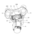
図5は、破砕機構2における一部を下方から見た斜視図である。図5においては、駆動機構20のモータ8を示すと共に、回転部分である回転軸12、および停留部分である容器保持部14を示している。図5においては、破砕本体部9および台座10などの固定部分を省略している。
Figure 5 is a perspective view of a part of the crushing
図5に示すように、モータ8の駆動軸11はカップリング19を介して回転軸12に連結されている。図4に示したように、回転軸12の先端には傾斜軸18が突設されており、この傾斜軸18に停留部分である容器保持部14の本体部分となる容器保持本体部24が設けられている。容器保持本体部24は、破砕本体部9の上面に対向する下面を有している。この容器保持本体部24の下面には、下側マグネット(第1マグネット)22に対向するように複数の上側マグネット(第2マグネット)23が実質的に等間隔で同一円周上に配設されている。即ち、上側マグネット23は、下側マグネット22の配設位置と同様に、その中心角度が60度間隔で6個が配設されており、傾斜軸18の中心軸に直交する面において、同一円周上の位置であり、傾斜軸18の中心軸から等距離の位置に配設されている。傾斜軸18の中心軸から等距離の位置が上側マグネット23の中心位置となっている。また、容器保持本体部24の下面に等間隔で配設された上側マグネット23は、下側マグネット22と同様に、その極性(N極、S極)が交互となるように配置されている。即ち、破砕機構2においては、容器保持本体部24の上側マグネット23と、破砕本体部9の下側マグネット22とにおける対向する位置のマグネット(22、23)は、極性の異なる配置となる。
As shown in FIG. 5, the
上記のように、下側マグネット22を備える破砕本体部9に対して、上側マグネット23を備える容器保持本体部24が斜行して配設されて、容器保持本体部24が3次元的な振動動作(破砕動作)を行う構成であるが、下側マグネット22と上側マグネット23とにおける最接近時の間隔は、磁石の仕様、電動機であるモータ8の仕様、電動機負荷の状態などに応じて所定の隙間、例えば、2mm~10mmの距離となるように設定される。実施の形態1において用いた上側マグネット23は、前述の下側マグネット22と同様の仕様のものを用いたが、異なる仕様のものを用いてもよい。
As described above, the container-holding
なお、実施の形態1の構成においては、破砕本体部9の上面に下側マグネット(第1マグネット)22を設け、容器保持本体部24の下面に上側マグネット(第2マグネット)23を設けた構成であるが、下側マグネット(第1マグネット)22および上側マグネット(第2マグネット)23は対向する面に設けられていればよく、例えば、それぞれのマグネット(22、23)が対向する面において段差を有する面に設けられていてもよい。
In the configuration of
上記のように、実施の形態1における回動拘束機構においては、固定部分である破砕本体部9の上面には複数(偶数個)の下側マグネット22が実質的に等間隔で同一円周上に配設されている。一方、停留部分である容器保持部14の容器保持本体部24の下面には、下側マグネット22に対向可能なように、下側マグネット22の配設位置と同様に上側マグネット23が実質的に等間隔で同一円周上に配設されている。また、上側マグネット23および下側マグネット22は、その極性(N極、S極)が交互となるように配置されているため、対向する面においてN極とS極のマグネット(22、23)は互いに対向する配置となる。このため、破砕本体部9の上面と容器保持本体部24の下面との間には所定の位置で大きな吸引力が生じ、停留部分(容器保持部14など)が固定部分(破砕本体部9など)に対して一定の領域内で確実に停留して、破砕動作が行われる構成となる。
As described above, in the rotation restraint mechanism in the first embodiment, a plurality (even number) of
なお、実施の形態1における回動拘束機構においては、破砕本体部9の上面に設けられた複数の下側マグネット(第1マグネット)22が、回転軸12の回転中心軸Aを中心とした円周上に沿って配設されており、容器保持部14の容器保持本体部24の下面に設けられた複数の上側マグネット(第2マグネット)23が、傾斜軸18の傾斜中心軸Bを中心とした円周上に沿って配設されている。また、破砕本体部9の上面は、回転軸12の回転中心軸Aに直交する面であり、容器保持本体部24の下面は、傾斜軸18の傾斜中心軸Bに直交する面である。このため、容器保持本体部24の下面は、破砕本体部9の上面に対して斜行した面となる。この結果、回転軸12の回転による容器保持本体部24の3次元的な振動動作により、対向する下側マグネット22と上側マグネット23は接近したり、離れたりの動作を繰り返す。対向する下側マグネット22と上側マグネット23においては、最接近したときに対向するマグネットの配設位置が略完全に対向する位置となるように配設されており、最も吸引力が生じるように構成されている。
In the rotation restraint mechanism in the first embodiment, the multiple lower magnets (first magnets) 22 provided on the upper surface of the crushing
従って、容器保持本体部24の下面に設けられた複数の上側マグネット(第2マグネット)23が下側マグネット(第1マグネット)22に最接近したときに、上側マグネット(第2マグネット)23の下端面となる磁力面が、対向する下側マグネット22の上端面の磁力面と平行となるように配設して、大きな吸引力を発生可能な構成としてもよい、
Therefore, when the multiple upper magnets (second magnets) 23 provided on the underside of the
上記のように、実施の形態1の破砕装置1においては、容器保持部14が回動拘束機構の磁気的拘束力を対向する面間に発生させて、傾斜軸18により旋回運動する回転部分と一緒に回転することが規制されて、一定領域内に停留した状態で3次元的な往復運動を行う。このため、容器保持部14が保持するホルダ(破砕容器13a)13は、一定の領域内において、前後左右のあらゆる方向に揺動しつつ、上下に往復運動する3次元的な振動動作(破砕動作)を行うこととなる。
As described above, in the crushing
なお、実施の形態1の破砕装置1において、容器保持部14を回動可能に保持する容器保持用軸受16を交換する場合には、後述するストッパ25を外して、容器保持部14を回転させて対向するマグネットの極性を同じとすることにより、容器保持部14の取り外しが容易となる。また、発明者の実験によれば、実施の形態1における回動拘束機構のように、対向する面に極性の異なる磁石を交互に配置する構成においては、駆動機構20(モータ8)における負荷の挙動が安定し、回転軸12の回転が滑らかであり、容器保持部14が所定の領域内で安定して3次元的な往復運動(破砕動作)が行われることを確認した。
When replacing the
[3次元往復運動機構]
次に、実施の形態1の破砕装置1において、容器保持部14を一定の領域内で3次元的な往復運動で駆動するための3次元往復運動機構について説明する。
[Three-dimensional reciprocating mechanism]
Next, a three-dimensional reciprocating mechanism for driving the
前述のように、実施の形態1の破砕装置1における破砕機構2においては、容器保持部14を3次元的な往復運動で駆動するために、駆動機構20における電動機であるモータ8の駆動軸11に連結された回転軸12に対して、偏心した位置から所定の角度(θ)だけ傾斜して延びる傾斜軸18が突設されている。この傾斜軸18に対して相対回転可能に容器保持用軸受16を介して容器保持部14が設けられている。また、モータ8の起動による回転軸12の回転動作に伴って、容器保持部14が一緒に旋回運動を起こさないように、前述の回動拘束機構が設けられている。
As described above, in the crushing
図6は、破砕機構2における駆動機構20のモータ8と、モータ8の駆動軸11にカップリング19を介して連結された回転軸12および傾斜軸18を示す側面図である。図6において、モータ8の駆動軸11に連結された回転軸12の中心軸を回転中心軸Aと称し、その回転中心軸Aに対して所定角度θを有して傾斜して突設された傾斜軸18の中心軸を傾斜中心軸Bと称する。また、回転中心軸Aと傾斜中心軸Bとの交点Pは、傾斜軸18に容器保持用軸受16および容器保持部14の取付け位置にある。この交点Pが容器保持部14の破砕動作の運動の中心位置となる。従って、傾斜軸18の傾斜中心軸Bは、回転軸12の突出端において回転中心軸Aの位置から偏心した位置となる。従って、破砕動作の運動の中心位置となる交点Pにおいて、傾斜軸18に直交する面上に複数のホルダ13の中心位置(破砕容器13aを含むホルダ13の略重心位置)が同心円上に配置された構成である。
Figure 6 is a side view showing the
傾斜軸18は、回転軸12の回転中心軸Aに対して所定の傾斜角度θ、例えば、数度~十数度程度の範囲の角度(実施の形態1の構成においては、傾斜角度θとして、例えば、8度に設定)を有しており、回転軸12の突出端における偏心した位置に突設されている。従って、回転軸12の回転動作に伴って、傾斜軸18は旋回運動する。傾斜軸18の旋回運動に伴い、容器保持部14も一緒に旋回運動を起動しようとするが、前述の回動拘束機構による磁気的拘束力により容器保持部14の旋回運動が規制されている。この結果、容器保持部14は一定の領域内において停留した状態で前後左右のあらゆる方向に揺動しつつ、上下に往復運動して3次元的な振動動作を行う。即ち、この3次元的な振動動作においては、容器保持部14に保持されたホルダ13(破砕容器13a)が前後左右に揺動されると共に、同時に上下に高速度で往復運動される。このとき稼働しているモータ8の回転数としては数千回転(例えば、2000~5000rpm)の所望の速度に駆動制御されている。このように、容器保持部14に保持されたホルダ13および破砕容器13aに対しては、3次元的な振動動作(破砕動作)が高速で行われるため、破砕容器13aの内部に収容された破砕用媒体が分析対象物に衝突して、分析対象物が確実に破砕される。なお、容器保持部14は容器保持用軸受16を含む構成としてもよい。
The
実施の形態1の破砕装置1においては、破砕本体部9に上方に突出した棒状のストッパ25が設けられている(図4参照)。ストッパ25は、容器保持部14にホルダ13を装着する場合や、ホルダ13の内部に破砕容器13aを収容して蓋をホルダ13に締め付けて取り付ける場合に、容器保持部14の無用な回転移動を防止するために設けられている。容器保持部14が一定角度回転したとき、容器保持部14の容器保持本体部24に形成された凹部24a(図5参照)の縁にストッパ25の突出端が当接して、容器保持部14の回転移動が禁止される構成である。
In the crushing
なお、破砕装置1において、容器保持部14が一定の領域内に停留した状態で、3次元的な振動動作(破砕動作)を行うときには、容器保持部14は回動拘束機構により回転移動せずに一定の領域内で停留した状態である。このため、ストッパ25の突出端は、破砕動作中においては、容器保持本体部24の凹部24aの内部に配置された状態である。破砕動作において、ストッパ25の突出端が容器保持本体部24の凹部24aの内部に配置されるように、回転拘束機構における永久磁石の位置を所望の位置に配置することにより、ストッパ25の突出端が容器保持本体部24の凹部24aの内部の所望の位置に維持するよう構成することが可能である。
When the crushing
上記のように、実施の形態1の破砕装置1においては、停留部分であるホルダ13を保持する容器保持部14と、固定部分である破砕本体部9との対向するそれぞれの面に、対向して複数(偶数)の磁石が配設された回動拘束機構が設けられている。また、回動拘束機構においては、対向して配置される磁石が、対向する面においてN極とS極とが交互に配設されており、停留部分と固定部分とが所定の位置で互いに強く吸引すると共に、停留部分が固定部分に対して回転しようとしても、互いの対向する面において隣接する同極の永久磁石に対して反発し、所定の位置に確実に保持される構成となっている。
As described above, in the crushing
実施の形態1の破砕装置1においては、停留部分である容器保持部14を一定の領域内において3次元的に高速度で振動動作(破砕動作)を行うために、上記のように構成された回動拘束機構を伴う3次元往復運動機構が設けられている、このため、破砕動作において、破砕容器13aの内部に収容された破砕用媒体が分析対象物に衝突して、分析対象物が確実に破砕される構成となる。実施の形態1の破砕装置1は、複雑な動きを行う破砕容器13aを保持するための保持機構を、簡単で信頼性の高い機構で構成して、小型化を達成しつつ、安定性、確実性、および信頼性の高いものとなっている。
In the crushing
(実施の形態2)
以下、本発明に係る実施の形態2の破砕装置1について、図面を参照しながら説明する。なお、実施の形態2における説明では、実施の形態1との相違点を中心に説明する。なお、実施の形態2の説明において、前述の実施の形態1と同様の機能を有する要素には同じ参照符号を付し、重複する記載を避けるため説明を省略する場合がある。また、実施の形態2の破砕装置1における基本的な破砕動作は、実施の形態1における動作と同じであるので、実施の形態2においては実施の形態1と異なる点を主として説明する。
(Embodiment 2)
Hereinafter, the crushing
実施の形態2の破砕装置1において、実施の形態1の破砕装置1と異なる構成は、固定部分である破砕装置本体部9の上面に配設した下側マグネット(第1マグネット)22、および停留部分である容器保持本体部24の下面に配設した上側マグネット(第2マグネット)23における数と配置であり、その他の構成は同じである。
The crushing
図7は、実施の形態2における破砕機構2における固定部分である破砕本体部9、および回転部分であるモータ8の起動により旋回運動する傾斜軸18を含む回転軸12を上方から見た斜視図である。図7においては、前述の実施の形態1において説明した図4と同様に、弾性部材5が固定される下部ケース3bを省略している。
Figure 7 is a perspective view from above of the crushing
図7に示すように、固定部分である破砕本体部9の上面には4個の下側マグネット22が実質的に等間隔で同一円周上に配設されている。即ち、実施の形態2の構成においては、下側マグネット22は、破砕本体部9の上面において、その中心角度が90度の間隔で4個が配設されており、回転軸12の回転中心から等距離の位置が下側マグネット22の中心位置となるように配置されている。また、破砕本体部9の上面に配設した複数の下側マグネット22においては、その極性(N極、S極)が交互となるように配置されている。
As shown in FIG. 7, four
図8は、実施の形態2における駆動機構であるモータ8を示すと共に、停留部分となる容器保持部14を下方から見た斜視図である。図8においては、前述の実施の形態1において説明した図5と同様に、破砕本体部9および台座10などの固定部分を省略している。
Figure 8 shows the
図8に示すように、モータ8の駆動軸11がカップリング19を介して回転軸12に連結されている。実施の形態1の構成と同様に、回転軸12の先端には傾斜軸18が突設されており、この傾斜軸18に停留部分である容器保持部14の本体部分となる容器保持本体部24が設けられている。容器保持本体部24の下面には、破砕本体部9の上面に配設された下側マグネット(第1マグネット)22に対向するように4個の上側マグネット(第2マグネット)23が実質的に等間隔で同一円周上に配設されている。即ち、上側マグネット23は、下側マグネット22の配設位置と同様に、その中心角度が90度の間隔で4個が配設されており、傾斜軸18の中心から等距離の位置が上側マグネット23の中心位置となるように配置されている。また、容器保持本体部24の下面に等間隔で配設された上側マグネット23は、下側マグネット22と同様に、その極性(N極、S極)が交互となるように配置されている。なお、実施の形態2において用いた下側マグネット22と上側マグネット23は、同様の仕様である。
As shown in FIG. 8, the
上記のように、実施の形態2における回動拘束機構においては、固定部分である破砕本体部9の上面には4個の下側マグネット22が実質的に等間隔で配設され、一方、停留部分である容器保持本体部24の下面には、下側マグネット22に対向するように同様の配設位置に上側マグネット23が実質的に等間隔で配設されている。さらに、下側マグネット22および上側マグネット23は、その極性(N極、S極)が交互となるように配置されている。このため、対向する位置のN極とS極のマグネット(22、23)は互いに吸引力が発生すると共に、対向するマグネットに隣接するマグネットに対しては極性が同じであるため反発力が生じ、停留部分(容器保持部14など)が固定部分(破砕本体部9など)に対して一定の領域内で確実に停留状態となる構成である。
As described above, in the rotation restraint mechanism in
また、実施の形態2の破砕装置1は、実施の形態1において説明した3次元往復運動機構を備えている。このため、実施の形態2の破砕装置1においては、容器保持部14が回動拘束機構の磁気的拘束力により、傾斜軸18の旋回運動と一緒に回転することなく、一定領域に停留した状態で前後左右のあらゆる方向に揺動しつつ、実質的に上下方向に往復運動を行う。この結果、容器保持部14に保持されたホルダ13は、破砕本体部9の固定部分に対して一定の領域内で3次元的な振動動作を行い、所望の破砕動作が行われる。
The crushing
上記のように、実施の形態2の破砕装置1においては、上記のように構成された回動拘束機構を伴う3次元往復運動機構が設けられているため、破砕動作において破砕容器13aの内部に収容された破砕用媒体が分析対象物に衝突して、分析対象物が確実に破砕される構成となる。実施の形態2の破砕装置1は、複雑な動きを行う破砕容器13aを保持するための保持機構を、簡単で信頼性の高い機構で構成して、小型化を達成しつつ、安定性、確実性、および信頼性の高いものとなっている。
As described above, the crushing
(実施の形態3)
以下、本発明に係る実施の形態3の破砕装置1について、図面を参照しながら説明する。なお、実施の形態3における説明では、実施の形態1および実施の形態2との相違点を中心に説明する。なお、実施の形態3の説明において、前述の実施の形態1と同様の機能を有する要素には同じ参照符号を付し、重複する記載を避けるため説明を省略する場合がある。また、実施の形態3の破砕装置1における基本的な破砕動作は、実施の形態1における動作と同じであるので、実施の形態3においては実施の形態1および実施の形態2と異なる点を主として説明する。
(Embodiment 3)
Hereinafter, the crushing
実施の形態3の破砕装置1において、実施の形態1の破砕装置1と異なる構成は、固定部分である破砕装置本体部9の上面に配設した下側マグネット(第1マグネット)22、および停留部分である容器保持本体部24の下面に配設した上側マグネット(第2マグネット)23における配設位置であり、その他の構成は同じである。
The crushing
図9は、実施の形態3における破砕機構2における固定部分である破砕本体部9、および回転部分であるモータ8の起動により旋回運動する傾斜軸18を含む回転軸12を上方から見た斜視図である。図9においては、前述の実施の形態1において説明した図4と同様に、弾性部材5が固定される下部ケース3bを省略している。
Figure 9 is a perspective view from above of the crushing
図9に示すように、固定部分である破砕本体部9の上面には6個の下側マグネット22が配設されている。実施の形態3においては、3個の下側マグネット22が互いに隣接するように配設されて1つのマグネット群(第1下側マグネット群22A)が構成されている。また、前記の第1下側マグネット群22Aに対して回転軸12を間にして対向する位置に3個の下側マグネット22が互いに隣接するように配設されて1つのマグネット群(第2下側マグネット群22B)が構成されている。第1下側マグネット群22Aにおいては、その中央位置にN極の永久磁石(22)が配置され、その両側にS極の永久磁石(22)が配置される構成である。一方、第2下側マグネット群22Bにおいては、その中央位置にS極の永久磁石(22)が配置され、その両側にN極の永久磁石(22)が配置される構成である。即ち、回転軸12を挟んで対向する第1下側マグネット群22Aおよび第2下側マグネット群22Bにおいては極性の配置が異なっている。
As shown in FIG. 9, six
図10は、実施の形態3における駆動機構であるモータ8を示すと共に、停留部分となる容器保持部14を下方から見た斜視図である。図10においては、前述の実施の形態1において説明した図5と同様に、破砕本体部9および台座10などの固定部分を省略している。
Figure 10 shows the
実施の形態3の構成においても、実施の形態1の構成と同様に、図10に示すように、モータ8の駆動軸11がカップリング19を介して回転軸12に連結されている。回転軸12の先端には傾斜軸18が突設されており、この傾斜軸18に停留部分である容器保持部14の本体部分となる容器保持本体部24が設けられている。容器保持本体部24の下面には、破砕本体部9の上面に配設された第1下側マグネット群22Aおよび第2下側マグネット群22Bに対向するように、第1上側マグネット群23Aおよび第2上側マグネット群23Bが配設さている。即ち、上側マグネット23は、第1下側マグネット群22Aおよび第2下側マグネット群22Bと同様に、3個の上側マグネット23が互いに隣接するように配設されて1つのマグネット群が構成されている。また、第1上側マグネット群23Aにおいては、その中央位置にS極の永久磁石(23)が配置され、その両側にN極の永久磁石(23)が配置される構成である。一方、第2上側マグネット群23Bにおいては中央位置にN極の永久磁石(23)が配置され、その両側にS極の永久磁石(23)が配置される構成である。即ち、回転軸12を挟んで対向する第1上側マグネット群23Aおよび第2上側マグネット群23Bにおいては極性の配置が異なっている。なお、実施の形態3において用いた下側マグネット22と上側マグネット23とは、同様の仕様である。
In the configuration of the third embodiment, as in the configuration of the first embodiment, as shown in FIG. 10, the
上記のように、実施の形態3における回動拘束機構は、固定部分である破砕本体部9の上面、および停留部分である容器保持本体部24の下面という対向面において、対向するように複数のマグネット群を極性が異なる配置で設けた構成である。このため、停留部分(容器保持部14など)と固定部分(破砕本体部9など)との上下位置で対向するN極とS極の永久磁石(22、23)は大きな吸引力で吸引される構成となり、停留部分が固定部分に対して一定の領域内で確実に停留した状態が保持される構成となる。
As described above, the rotation restraint mechanism in embodiment 3 is configured such that multiple magnet groups are arranged with different polarities to face each other on opposing surfaces, namely the upper surface of the crushing
また、実施の形態3の破砕装置1は、実施の形態1において説明した3次元往復運動機構を備えている。このため、実施の形態3の破砕装置1においては、容器保持部14が回動拘束機構の磁気的拘束力により、傾斜軸18の旋回運動と一緒に回転することなく、一定領域に停留した状態で前後左右のあらゆる方向に揺動しつつ、実質的に上下方向に往復運動して、容器保持部14に保持されたホルダ13は破砕本体部9の固定部分に対して一定の領域内で3次元的な振動動作を行い、確実な破砕動作が行われる構成である。
The crushing
上記のように、実施の形態3の破砕装置1においては、上記のように構成された回動拘束機構を伴う3次元往復運動機構が設けられているため、破砕動作において破砕容器13aの内部に収容された破砕用媒体が分析対象物に衝突して、分析対象物が確実に破砕される構成となる。実施の形態3の破砕装置1は、複雑な動きを行う破砕容器13aを保持するための保持機構を、簡単で信頼性の高い機構で構成して、小型化を達成しつつ、安定性、確実性、および信頼性の高いものとなっている。
As described above, the crushing
なお、本発明に係る実施の形態1、2、3の破砕装置1においては、破砕容器13aを保持するための容器保持部14が、板材の加工により簡単に形成することが可能な構成を有しており、軽量化を図ることが可能な構成である。この結果、駆動機構の負荷が軽減され、駆動源となるモータなどに関する省エネルギー化、高速運転化、装置の軽量化、および小型化などを達成することが可能な構成となる。
In the crushing
また、本発明に係る実施の形態1、2、3の破砕装置1は、容器保持部14が液体窒素により冷却された破砕容器13aを保持して破砕動作を行うことが可能な構成であり、ホルダ13の頂部には断熱部を設けることが可能な構成としてもよい。なお、本発明の破砕装置としては、実施の形態1、2、3で説明した構成に限定されるものではなく、容器保持部が冷却水循環経路を有する構造として、冷却水による冷却が可能な構造としてもよい。
The crushing
本発明の破砕装置は、実施の形態1、2、3において説明した構成、およびその構成と同様の技術的思想に基づく構成とすることにより、小型で、信頼性の高い回動拘束機構および3次元往復運動機構が設けられるため、小型化を達成することができると共に、安定性、確実性および信頼性が高い破砕装置を構築することが可能となる。 The crushing device of the present invention is configured based on the configurations described in the first, second, and third embodiments, and on the same technical ideas as those configurations, and is provided with a small, highly reliable rotation restraint mechanism and three-dimensional reciprocating mechanism, making it possible to achieve miniaturization and to construct a crushing device that is stable, reliable, and secure.
本発明をある程度の詳細さをもって実施の形態において説明したが、これらの構成は例示であり、実施の形態の開示内容は構成の細部において変化してしかるべきものである。本発明においては、実施の形態における要素の置換、組合せ、および順序の変更は請求された本発明の範囲及び思想を逸脱することなく実現し得るものである。 Although the present invention has been described in the embodiments with a certain degree of detail, these configurations are exemplary and the disclosure of the embodiments may vary in the details of the configuration. In the present invention, substitutions, combinations, and changes in the order of elements in the embodiments may be made without departing from the scope and spirit of the invention as claimed.
以上のように、本発明における技術の例示として、実施の形態を説明した。そのために、詳細な説明および添付の図面を開示した。よって、詳細な説明および添付の図面に記載された構成要素の中には、課題解決のために必須でない構成要素が含まれることがある。したがって、それらの必須でない構成要素が、詳細な説明および添付の図面に記載されているからといって、直ちに、それらの必須ではない構成要素に対して必須であると認定されるべきではない。 As described above, the embodiment has been described as an example of the technology of the present invention. For that purpose, the detailed description and the attached drawings have been disclosed. Therefore, the components described in the detailed description and the attached drawings may include components that are not essential for solving the problem. Therefore, just because those non-essential components are described in the detailed description and the attached drawings, they should not be immediately recognized as essential to those non-essential components.
本発明は、安定性、確実性および信頼性の高い破砕装置を提供するものであり、微生物、植物組織、動物組織、有機材料、無機材料などの各種試料を分析する場合において有用な破砕装置となり、市場価値の高い製品を提供できる。
The present invention provides a homogenizer that is stable, reliable and sure, and is useful when analyzing various samples such as microorganisms, plant tissues, animal tissues, organic materials, inorganic materials, etc., and can provide a product with high market value.
1 破砕装置
2 破砕機構
3 ケース
3a 上部ケース
3b 下部ケース
4 ヒンジ部
5 弾性部材
6 操作部
7 制御部
8 モータ
9 破砕本体部(固定部分)
10 台座
11 駆動軸
12 回転軸
13 ホルダ
13a 破砕容器
14 容器保持部(停留部分)
15 傾斜軸(回転部分)
16 容器保持用軸受
17 本体部軸受
18 傾斜軸
19 カップリング
20 駆動機構
21 モータ固定部材
22 下側マグネット(第1マグネット)
23 上側マグネット(第2マグネット)
24 容器保持本体部(停留部分)
24a 凹部
25 ストッパ
26 伸縮部材
A 回転中心軸
B 傾斜中心軸
P 交点(破砕動作の運動中心位置)
REFERENCE SIGNS
REFERENCE SIGNS
15 Tilt axis (rotating part)
16
23 Upper magnet (second magnet)
24 Container holding main body (retention part)
24a: Recess 25: Stopper 26: Expandable member A: Rotation axis B: Tilt axis P: Intersection (center of movement of crushing operation)
Claims (8)
前記回転軸の回転中心軸に対して所定の傾斜角度を有する傾斜軸と、
前記傾斜軸の傾斜中心軸の周りを回動可能に保持され、破砕容器を収容するホルダを保持する容器保持部と、
前記電動機と共に固定され、前記容器保持部に対向する面を有する破砕本体部と、
前記容器保持部と前記破砕本体部との対向する面のそれぞれに対向するように配設された複数の磁石で構成された回動拘束機構と、を備え、
前記容器保持部と前記破砕本体部との対向する面のそれぞれにおいて隣接する磁石の極性が異なるように構成された、破砕装置。 A rotating shaft that is rotated by an electric motor;
an inclined axis having a predetermined inclination angle with respect to a central axis of rotation of the rotation shaft;
a container holding part that holds a holder that is rotatably held around a tilt central axis of the tilt shaft and that houses a crushing container;
A crushing main body portion fixed together with the electric motor and having a surface facing the container holding portion;
A rotation restriction mechanism is provided, the rotation restriction mechanism being configured with a plurality of magnets arranged to face each of the opposing surfaces of the container holding unit and the crushing main unit,
A crushing device configured such that adjacent magnets on each of the opposing surfaces of the container holding part and the crushing main body have different polarities.
前記容器保持部が所定角度以上に回動すると前記ストッパが当接して、前記容器保持部の回動を禁止するように構成された、請求項1から6のいずれか一項に記載の破砕装置。 A stopper is provided which is fixed to the crushing body.
The crushing device according to claim 1 , wherein the stopper is contacted with the container holder when the container holder is rotated by a predetermined angle or more to prohibit the container holder from rotating.
前記回転軸の突出端において、前記傾斜軸が前記回転軸の回転中心軸の位置から偏心した位置で所定の傾斜角度を有して上方に突設され、
前記回転軸の回転中心軸と前記傾斜軸の傾斜中心軸との交点の位置が破砕動作の運動中心位置となるように前記容器保持部を前記傾斜軸に回動可能に設けた、請求項1から7のいずれか一項に記載の破砕装置。 The rotation shaft is provided so as to protrude upward in a vertical direction,
The inclined shaft is provided at a protruding end of the rotating shaft, protruding upward at a position eccentric to the position of the rotation center axis of the rotating shaft and having a predetermined inclination angle,
8. The crushing device according to claim 1, wherein the container holding part is rotatably mounted on the tilting axis so that the intersection of the rotation center axis of the rotating axis and the tilting center axis of the tilting axis becomes the center of movement of the crushing operation.
Priority Applications (1)
| Application Number | Priority Date | Filing Date | Title |
|---|---|---|---|
| JP2020182719A JP7549335B2 (en) | 2020-10-30 | 2020-10-30 | Crushing Equipment |
Applications Claiming Priority (1)
| Application Number | Priority Date | Filing Date | Title |
|---|---|---|---|
| JP2020182719A JP7549335B2 (en) | 2020-10-30 | 2020-10-30 | Crushing Equipment |
Publications (2)
| Publication Number | Publication Date |
|---|---|
| JP2022072985A JP2022072985A (en) | 2022-05-17 |
| JP7549335B2 true JP7549335B2 (en) | 2024-09-11 |
Family
ID=81604118
Family Applications (1)
| Application Number | Title | Priority Date | Filing Date |
|---|---|---|---|
| JP2020182719A Active JP7549335B2 (en) | 2020-10-30 | 2020-10-30 | Crushing Equipment |
Country Status (1)
| Country | Link |
|---|---|
| JP (1) | JP7549335B2 (en) |
Citations (7)
| Publication number | Priority date | Publication date | Assignee | Title |
|---|---|---|---|---|
| JP2000023660A (en) | 1998-07-09 | 2000-01-25 | Yasui Kikai Kk | Cell disruption device |
| US20030146313A1 (en) | 2002-02-01 | 2003-08-07 | Monsanto Technology Llc | Axially reciprocating tubular ball mill grinding device and method |
| JP2003251207A (en) | 2002-03-05 | 2003-09-09 | Yasui Kikai Kk | Crushing equipment |
| JP2004050031A (en) | 2002-07-19 | 2004-02-19 | Scinics:Kk | Crushing apparatus |
| JP2004313966A (en) | 2003-04-17 | 2004-11-11 | Yasui Kikai Kk | Cell disruption device |
| JP2005534480A (en) | 2002-08-01 | 2005-11-17 | ベルタン・テクノロジーズ・ソシエテ・アノニム | Equipment for vibrating a tube containing a sample at high speed |
| JP5351242B2 (en) | 2011-11-17 | 2013-11-27 | 有限会社興国産業 | Crusher |
-
2020
- 2020-10-30 JP JP2020182719A patent/JP7549335B2/en active Active
Patent Citations (7)
| Publication number | Priority date | Publication date | Assignee | Title |
|---|---|---|---|---|
| JP2000023660A (en) | 1998-07-09 | 2000-01-25 | Yasui Kikai Kk | Cell disruption device |
| US20030146313A1 (en) | 2002-02-01 | 2003-08-07 | Monsanto Technology Llc | Axially reciprocating tubular ball mill grinding device and method |
| JP2003251207A (en) | 2002-03-05 | 2003-09-09 | Yasui Kikai Kk | Crushing equipment |
| JP2004050031A (en) | 2002-07-19 | 2004-02-19 | Scinics:Kk | Crushing apparatus |
| JP2005534480A (en) | 2002-08-01 | 2005-11-17 | ベルタン・テクノロジーズ・ソシエテ・アノニム | Equipment for vibrating a tube containing a sample at high speed |
| JP2004313966A (en) | 2003-04-17 | 2004-11-11 | Yasui Kikai Kk | Cell disruption device |
| JP5351242B2 (en) | 2011-11-17 | 2013-11-27 | 有限会社興国産業 | Crusher |
Also Published As
| Publication number | Publication date |
|---|---|
| JP2022072985A (en) | 2022-05-17 |
Similar Documents
| Publication | Publication Date | Title |
|---|---|---|
| US20170310203A1 (en) | Actuator | |
| US5399013A (en) | Mixing device | |
| CN112410214B (en) | Rail mounted vibration incubator | |
| CN101707941B (en) | Multistation device for mixing the contents of laboratory vessels | |
| JP2019020464A (en) | Optical unit with shake correction function | |
| JP5815724B2 (en) | Mixing device with bearing device for storage device | |
| JP7549335B2 (en) | Crushing Equipment | |
| WO2012105252A1 (en) | Stirring device and stirring method | |
| JP2015519198A (en) | A ball mill that offsets imbalances in three dimensions | |
| KR101335339B1 (en) | Apparatus for pulverization with reciprocating mill | |
| JPS6350054B2 (en) | ||
| JP2003251207A (en) | Crushing equipment | |
| US20050180258A1 (en) | Vortexer | |
| JP2007203244A (en) | Crushing and agitating method | |
| JP2010194397A (en) | Sample crushing implement | |
| JP2006006372A (en) | Malaxation apparatus for dental restoration | |
| CN101213012B (en) | Device and method for displacing liquid containers | |
| JP2020085604A (en) | Device and method for inspecting foreign substance in material filled in transparent container | |
| JP5351242B2 (en) | Crusher | |
| JP2008023504A (en) | Magnetic crushing method, magnetic crushing device, and crushing medium used for it | |
| US10739236B1 (en) | Apparatus and method for vortex mixing and cell disruption of a laboratory sample | |
| JP2000202314A (en) | Cell disruption device | |
| JP3732137B2 (en) | Crusher | |
| JP2004313966A (en) | Cell disruption device | |
| JP4974104B2 (en) | Eccentric rotary sample crusher |
Legal Events
| Date | Code | Title | Description |
|---|---|---|---|
| A621 | Written request for application examination |
Free format text: JAPANESE INTERMEDIATE CODE: A621 Effective date: 20230605 |
|
| A977 | Report on retrieval |
Free format text: JAPANESE INTERMEDIATE CODE: A971007 Effective date: 20240417 |
|
| A131 | Notification of reasons for refusal |
Free format text: JAPANESE INTERMEDIATE CODE: A131 Effective date: 20240507 |
|
| A521 | Request for written amendment filed |
Free format text: JAPANESE INTERMEDIATE CODE: A523 Effective date: 20240515 |
|
| TRDD | Decision of grant or rejection written | ||
| A01 | Written decision to grant a patent or to grant a registration (utility model) |
Free format text: JAPANESE INTERMEDIATE CODE: A01 Effective date: 20240813 |
|
| A61 | First payment of annual fees (during grant procedure) |
Free format text: JAPANESE INTERMEDIATE CODE: A61 Effective date: 20240823 |
|
| R150 | Certificate of patent or registration of utility model |
Ref document number: 7549335 Country of ref document: JP Free format text: JAPANESE INTERMEDIATE CODE: R150 |